EP4041944B1 - Knitted component having a foam surface feature - Google Patents
Knitted component having a foam surface feature Download PDFInfo
- Publication number
- EP4041944B1 EP4041944B1 EP20821564.0A EP20821564A EP4041944B1 EP 4041944 B1 EP4041944 B1 EP 4041944B1 EP 20821564 A EP20821564 A EP 20821564A EP 4041944 B1 EP4041944 B1 EP 4041944B1
- Authority
- EP
- European Patent Office
- Prior art keywords
- yarn
- foamable
- knitted component
- foam
- area
- Prior art date
- Legal status (The legal status is an assumption and is not a legal conclusion. Google has not performed a legal analysis and makes no representation as to the accuracy of the status listed.)
- Active
Links
Images


Classifications
-
- D—TEXTILES; PAPER
- D06—TREATMENT OF TEXTILES OR THE LIKE; LAUNDERING; FLEXIBLE MATERIALS NOT OTHERWISE PROVIDED FOR
- D06M—TREATMENT, NOT PROVIDED FOR ELSEWHERE IN CLASS D06, OF FIBRES, THREADS, YARNS, FABRICS, FEATHERS OR FIBROUS GOODS MADE FROM SUCH MATERIALS
- D06M15/00—Treating fibres, threads, yarns, fabrics, or fibrous goods made from such materials, with macromolecular compounds; Such treatment combined with mechanical treatment
- D06M15/19—Treating fibres, threads, yarns, fabrics, or fibrous goods made from such materials, with macromolecular compounds; Such treatment combined with mechanical treatment with synthetic macromolecular compounds
- D06M15/21—Macromolecular compounds obtained by reactions only involving carbon-to-carbon unsaturated bonds
- D06M15/327—Macromolecular compounds obtained by reactions only involving carbon-to-carbon unsaturated bonds of unsaturated alcohols or esters thereof
- D06M15/333—Macromolecular compounds obtained by reactions only involving carbon-to-carbon unsaturated bonds of unsaturated alcohols or esters thereof of vinyl acetate; Polyvinylalcohol
-
- D—TEXTILES; PAPER
- D04—BRAIDING; LACE-MAKING; KNITTING; TRIMMINGS; NON-WOVEN FABRICS
- D04B—KNITTING
- D04B1/00—Weft knitting processes for the production of fabrics or articles not dependent on the use of particular machines; Fabrics or articles defined by such processes
- D04B1/10—Patterned fabrics or articles
- D04B1/12—Patterned fabrics or articles characterised by thread material
-
- D—TEXTILES; PAPER
- D04—BRAIDING; LACE-MAKING; KNITTING; TRIMMINGS; NON-WOVEN FABRICS
- D04B—KNITTING
- D04B1/00—Weft knitting processes for the production of fabrics or articles not dependent on the use of particular machines; Fabrics or articles defined by such processes
- D04B1/14—Other fabrics or articles characterised primarily by the use of particular thread materials
- D04B1/16—Other fabrics or articles characterised primarily by the use of particular thread materials synthetic threads
-
- A—HUMAN NECESSITIES
- A43—FOOTWEAR
- A43B—CHARACTERISTIC FEATURES OF FOOTWEAR; PARTS OF FOOTWEAR
- A43B1/00—Footwear characterised by the material
- A43B1/0009—Footwear characterised by the material made at least partially of alveolar or honeycomb material
-
- A—HUMAN NECESSITIES
- A43—FOOTWEAR
- A43B—CHARACTERISTIC FEATURES OF FOOTWEAR; PARTS OF FOOTWEAR
- A43B1/00—Footwear characterised by the material
- A43B1/02—Footwear characterised by the material made of fibres or fabrics made therefrom
- A43B1/025—Plant fibres
-
- A—HUMAN NECESSITIES
- A43—FOOTWEAR
- A43B—CHARACTERISTIC FEATURES OF FOOTWEAR; PARTS OF FOOTWEAR
- A43B1/00—Footwear characterised by the material
- A43B1/02—Footwear characterised by the material made of fibres or fabrics made therefrom
- A43B1/028—Synthetic or artificial fibres
-
- A—HUMAN NECESSITIES
- A43—FOOTWEAR
- A43B—CHARACTERISTIC FEATURES OF FOOTWEAR; PARTS OF FOOTWEAR
- A43B23/00—Uppers; Boot legs; Stiffeners; Other single parts of footwear
- A43B23/02—Uppers; Boot legs
- A43B23/0205—Uppers; Boot legs characterised by the material
- A43B23/0225—Composite materials, e.g. material with a matrix
-
- A—HUMAN NECESSITIES
- A43—FOOTWEAR
- A43B—CHARACTERISTIC FEATURES OF FOOTWEAR; PARTS OF FOOTWEAR
- A43B23/00—Uppers; Boot legs; Stiffeners; Other single parts of footwear
- A43B23/02—Uppers; Boot legs
- A43B23/0205—Uppers; Boot legs characterised by the material
- A43B23/0235—Different layers of different material
-
- D—TEXTILES; PAPER
- D01—NATURAL OR MAN-MADE THREADS OR FIBRES; SPINNING
- D01D—MECHANICAL METHODS OR APPARATUS IN THE MANUFACTURE OF ARTIFICIAL FILAMENTS, THREADS, FIBRES, BRISTLES OR RIBBONS
- D01D11/00—Other features of manufacture
- D01D11/06—Coating with spinning solutions or melts
-
- D—TEXTILES; PAPER
- D01—NATURAL OR MAN-MADE THREADS OR FIBRES; SPINNING
- D01D—MECHANICAL METHODS OR APPARATUS IN THE MANUFACTURE OF ARTIFICIAL FILAMENTS, THREADS, FIBRES, BRISTLES OR RIBBONS
- D01D5/00—Formation of filaments, threads, or the like
- D01D5/24—Formation of filaments, threads, or the like with a hollow structure; Spinnerette packs therefor
- D01D5/247—Discontinuous hollow structure or microporous structure
-
- D—TEXTILES; PAPER
- D01—NATURAL OR MAN-MADE THREADS OR FIBRES; SPINNING
- D01D—MECHANICAL METHODS OR APPARATUS IN THE MANUFACTURE OF ARTIFICIAL FILAMENTS, THREADS, FIBRES, BRISTLES OR RIBBONS
- D01D5/00—Formation of filaments, threads, or the like
- D01D5/28—Formation of filaments, threads, or the like while mixing different spinning solutions or melts during the spinning operation; Spinnerette packs therefor
- D01D5/30—Conjugate filaments; Spinnerette packs therefor
- D01D5/34—Core-skin structure; Spinnerette packs therefor
-
- D—TEXTILES; PAPER
- D01—NATURAL OR MAN-MADE THREADS OR FIBRES; SPINNING
- D01F—CHEMICAL FEATURES IN THE MANUFACTURE OF ARTIFICIAL FILAMENTS, THREADS, FIBRES, BRISTLES OR RIBBONS; APPARATUS SPECIALLY ADAPTED FOR THE MANUFACTURE OF CARBON FILAMENTS
- D01F1/00—General methods for the manufacture of artificial filaments or the like
- D01F1/02—Addition of substances to the spinning solution or to the melt
- D01F1/08—Addition of substances to the spinning solution or to the melt for forming hollow filaments
-
- D—TEXTILES; PAPER
- D02—YARNS; MECHANICAL FINISHING OF YARNS OR ROPES; WARPING OR BEAMING
- D02G—CRIMPING OR CURLING FIBRES, FILAMENTS, THREADS, OR YARNS; YARNS OR THREADS
- D02G3/00—Yarns or threads, e.g. fancy yarns; Processes or apparatus for the production thereof, not otherwise provided for
- D02G3/22—Yarns or threads characterised by constructional features, e.g. blending, filament/fibre
- D02G3/40—Yarns in which fibres are united by adhesives; Impregnated yarns or threads
- D02G3/404—Yarns or threads coated with polymeric solutions
-
- D—TEXTILES; PAPER
- D04—BRAIDING; LACE-MAKING; KNITTING; TRIMMINGS; NON-WOVEN FABRICS
- D04B—KNITTING
- D04B1/00—Weft knitting processes for the production of fabrics or articles not dependent on the use of particular machines; Fabrics or articles defined by such processes
- D04B1/02—Pile fabrics or articles having similar surface features
- D04B1/04—Pile fabrics or articles having similar surface features characterised by thread material
-
- D—TEXTILES; PAPER
- D04—BRAIDING; LACE-MAKING; KNITTING; TRIMMINGS; NON-WOVEN FABRICS
- D04B—KNITTING
- D04B1/00—Weft knitting processes for the production of fabrics or articles not dependent on the use of particular machines; Fabrics or articles defined by such processes
- D04B1/10—Patterned fabrics or articles
- D04B1/12—Patterned fabrics or articles characterised by thread material
- D04B1/123—Patterned fabrics or articles characterised by thread material with laid-in unlooped yarn, e.g. fleece fabrics
-
- D—TEXTILES; PAPER
- D04—BRAIDING; LACE-MAKING; KNITTING; TRIMMINGS; NON-WOVEN FABRICS
- D04B—KNITTING
- D04B1/00—Weft knitting processes for the production of fabrics or articles not dependent on the use of particular machines; Fabrics or articles defined by such processes
- D04B1/22—Weft knitting processes for the production of fabrics or articles not dependent on the use of particular machines; Fabrics or articles defined by such processes specially adapted for knitting goods of particular configuration
-
- D—TEXTILES; PAPER
- D04—BRAIDING; LACE-MAKING; KNITTING; TRIMMINGS; NON-WOVEN FABRICS
- D04B—KNITTING
- D04B21/00—Warp knitting processes for the production of fabrics or articles not dependent on the use of particular machines; Fabrics or articles defined by such processes
- D04B21/20—Warp knitting processes for the production of fabrics or articles not dependent on the use of particular machines; Fabrics or articles defined by such processes specially adapted for knitting articles of particular configuration
-
- D—TEXTILES; PAPER
- D06—TREATMENT OF TEXTILES OR THE LIKE; LAUNDERING; FLEXIBLE MATERIALS NOT OTHERWISE PROVIDED FOR
- D06M—TREATMENT, NOT PROVIDED FOR ELSEWHERE IN CLASS D06, OF FIBRES, THREADS, YARNS, FABRICS, FEATHERS OR FIBROUS GOODS MADE FROM SUCH MATERIALS
- D06M15/00—Treating fibres, threads, yarns, fabrics, or fibrous goods made from such materials, with macromolecular compounds; Such treatment combined with mechanical treatment
- D06M15/19—Treating fibres, threads, yarns, fabrics, or fibrous goods made from such materials, with macromolecular compounds; Such treatment combined with mechanical treatment with synthetic macromolecular compounds
- D06M15/21—Macromolecular compounds obtained by reactions only involving carbon-to-carbon unsaturated bonds
- D06M15/227—Macromolecular compounds obtained by reactions only involving carbon-to-carbon unsaturated bonds of hydrocarbons, or reaction products thereof, e.g. afterhalogenated or sulfochlorinated
-
- D—TEXTILES; PAPER
- D06—TREATMENT OF TEXTILES OR THE LIKE; LAUNDERING; FLEXIBLE MATERIALS NOT OTHERWISE PROVIDED FOR
- D06M—TREATMENT, NOT PROVIDED FOR ELSEWHERE IN CLASS D06, OF FIBRES, THREADS, YARNS, FABRICS, FEATHERS OR FIBROUS GOODS MADE FROM SUCH MATERIALS
- D06M15/00—Treating fibres, threads, yarns, fabrics, or fibrous goods made from such materials, with macromolecular compounds; Such treatment combined with mechanical treatment
- D06M15/19—Treating fibres, threads, yarns, fabrics, or fibrous goods made from such materials, with macromolecular compounds; Such treatment combined with mechanical treatment with synthetic macromolecular compounds
- D06M15/37—Macromolecular compounds obtained otherwise than by reactions only involving carbon-to-carbon unsaturated bonds
- D06M15/507—Polyesters
-
- D—TEXTILES; PAPER
- D06—TREATMENT OF TEXTILES OR THE LIKE; LAUNDERING; FLEXIBLE MATERIALS NOT OTHERWISE PROVIDED FOR
- D06M—TREATMENT, NOT PROVIDED FOR ELSEWHERE IN CLASS D06, OF FIBRES, THREADS, YARNS, FABRICS, FEATHERS OR FIBROUS GOODS MADE FROM SUCH MATERIALS
- D06M15/00—Treating fibres, threads, yarns, fabrics, or fibrous goods made from such materials, with macromolecular compounds; Such treatment combined with mechanical treatment
- D06M15/19—Treating fibres, threads, yarns, fabrics, or fibrous goods made from such materials, with macromolecular compounds; Such treatment combined with mechanical treatment with synthetic macromolecular compounds
- D06M15/37—Macromolecular compounds obtained otherwise than by reactions only involving carbon-to-carbon unsaturated bonds
- D06M15/564—Polyureas, polyurethanes or other polymers having ureide or urethane links; Precondensation products forming them
-
- D—TEXTILES; PAPER
- D06—TREATMENT OF TEXTILES OR THE LIKE; LAUNDERING; FLEXIBLE MATERIALS NOT OTHERWISE PROVIDED FOR
- D06M—TREATMENT, NOT PROVIDED FOR ELSEWHERE IN CLASS D06, OF FIBRES, THREADS, YARNS, FABRICS, FEATHERS OR FIBROUS GOODS MADE FROM SUCH MATERIALS
- D06M23/00—Treatment of fibres, threads, yarns, fabrics or fibrous goods made from such materials, characterised by the process
- D06M23/04—Processes in which the treating agent is applied in the form of a foam
-
- D—TEXTILES; PAPER
- D06—TREATMENT OF TEXTILES OR THE LIKE; LAUNDERING; FLEXIBLE MATERIALS NOT OTHERWISE PROVIDED FOR
- D06M—TREATMENT, NOT PROVIDED FOR ELSEWHERE IN CLASS D06, OF FIBRES, THREADS, YARNS, FABRICS, FEATHERS OR FIBROUS GOODS MADE FROM SUCH MATERIALS
- D06M23/00—Treatment of fibres, threads, yarns, fabrics or fibrous goods made from such materials, characterised by the process
- D06M23/12—Processes in which the treating agent is incorporated in microcapsules
-
- A—HUMAN NECESSITIES
- A43—FOOTWEAR
- A43B—CHARACTERISTIC FEATURES OF FOOTWEAR; PARTS OF FOOTWEAR
- A43B1/00—Footwear characterised by the material
- A43B1/02—Footwear characterised by the material made of fibres or fabrics made therefrom
- A43B1/04—Footwear characterised by the material made of fibres or fabrics made therefrom braided, knotted, knitted or crocheted
-
- D—TEXTILES; PAPER
- D10—INDEXING SCHEME ASSOCIATED WITH SUBLASSES OF SECTION D, RELATING TO TEXTILES
- D10B—INDEXING SCHEME ASSOCIATED WITH SUBLASSES OF SECTION D, RELATING TO TEXTILES
- D10B2401/00—Physical properties
- D10B2401/04—Heat-responsive characteristics
- D10B2401/041—Heat-responsive characteristics thermoplastic; thermosetting
-
- D—TEXTILES; PAPER
- D10—INDEXING SCHEME ASSOCIATED WITH SUBLASSES OF SECTION D, RELATING TO TEXTILES
- D10B—INDEXING SCHEME ASSOCIATED WITH SUBLASSES OF SECTION D, RELATING TO TEXTILES
- D10B2401/00—Physical properties
- D10B2401/08—Physical properties foamed
-
- D—TEXTILES; PAPER
- D10—INDEXING SCHEME ASSOCIATED WITH SUBLASSES OF SECTION D, RELATING TO TEXTILES
- D10B—INDEXING SCHEME ASSOCIATED WITH SUBLASSES OF SECTION D, RELATING TO TEXTILES
- D10B2403/00—Details of fabric structure established in the fabric forming process
- D10B2403/02—Cross-sectional features
- D10B2403/024—Fabric incorporating additional compounds
- D10B2403/0241—Fabric incorporating additional compounds enhancing mechanical properties
-
- D—TEXTILES; PAPER
- D10—INDEXING SCHEME ASSOCIATED WITH SUBLASSES OF SECTION D, RELATING TO TEXTILES
- D10B—INDEXING SCHEME ASSOCIATED WITH SUBLASSES OF SECTION D, RELATING TO TEXTILES
- D10B2501/00—Wearing apparel
- D10B2501/04—Outerwear; Protective garments
- D10B2501/043—Footwear
-
- Y—GENERAL TAGGING OF NEW TECHNOLOGICAL DEVELOPMENTS; GENERAL TAGGING OF CROSS-SECTIONAL TECHNOLOGIES SPANNING OVER SEVERAL SECTIONS OF THE IPC; TECHNICAL SUBJECTS COVERED BY FORMER USPC CROSS-REFERENCE ART COLLECTIONS [XRACs] AND DIGESTS
- Y10—TECHNICAL SUBJECTS COVERED BY FORMER USPC
- Y10T—TECHNICAL SUBJECTS COVERED BY FORMER US CLASSIFICATION
- Y10T442/00—Fabric [woven, knitted, or nonwoven textile or cloth, etc.]
- Y10T442/40—Knit fabric [i.e., knit strand or strip material]
- Y10T442/469—Including a foamed layer or component
Definitions
- the present disclosure relates generally to knitted components and methods of manufacturing knitted components, for example, knitted components for use in footwear applications, apparel applications, or the like.
- a variety of articles are formed from textiles.
- articles of apparel e.g., shirts, pants, socks, footwear, jackets and other outerwear, briefs and other undergarments, hats and other headwear
- containers e.g., backpacks, bags
- upholstery for furniture e.g., chairs, couches, car seats
- textiles are often formed by weaving or interlooping (e.g., knitting) a yarn or a plurality of yarns, usually through a mechanical process involving looms or knitting machines.
- One particular object that may be formed from a textile is an upper for an article of footwear.
- Knitting is an example of a process that may form a textile. Knitting may generally be classified as either weft knitting or warp knitting. In both weft knitting and warp knitting, one or more yarns are manipulated to form a plurality of intermeshed loops that define a variety of courses and wales. In weft knitting, which is more common, the courses and wales are perpendicular to each other and may be formed from a single yarn or many yarns. In warp knitting, the wales and courses run roughly parallel.
- knitting may be performed by hand, the commercial manufacture of knitted components is generally performed by knitting machines.
- An example of a knitting machine for producing a weft knitted component is a V-bed flat knitting machine, which includes two needle beds that are angled with respect to each other. Rails extend above and parallel to the needle beds and provide attachment points for feeders, which move along the needle beds and supply yarns to needles within the needle beds. Standard feeders have the ability to supply a yarn that is utilized to knit, tuck, and float. In situations where an inlay yarn is incorporated into a knitted component, an inlay feeder is typically utilized.
- EP 2530195 A1 discloses a knitted/woven fabric comprising non-meshed intermediate layer made of jersey fabric which is inserted between the upper and lower layers of the fabric.
- FR 1176314 A discloses a fabric containing two distinct yarns, wherein the fabric is elastic in all directions.
- US 2019/037967 discloses a knitting component comprising a pod having a first surface formed by a first yarn and a second surface formed by a second yarn; and an edge region having a first surface formed by the second yarn and a second surface.
- the present invention provides a knitted component as defined in claim 1 and a method of preparing the knitted component as defined in claim 9. Preferred embodiments are set out in the dependent claims.
- Various aspects are described below with reference to the drawings in which like elements generally are identified by like numerals. The relationship and functioning of the various elements of the aspects may better be understood by reference to the following detailed description. However, aspects are not limited to those illustrated in the drawings or explicitly described below. It also should be understood that the drawings are not necessarily to scale, and in certain instances details may have been omitted that are not necessary for an understanding of aspects disclosed herein, such as conventional fabrication and assembly.
- a textile may be defined as a structure manufactured from fibers, filaments, or yarns characterized by flexibility, fineness, and a high ratio of length to thickness. Textiles generally fall into two categories. The first category includes textiles produced directly from webs of filaments or fibers by randomly (or non-randomly) interlocking or interconnecting to construct non-woven fabrics and felts. The second category includes textiles formed through a mechanical manipulation of yarn(s) (e.g., by interlacing or interlooping), thereby producing a woven fabric or a knitting fabric, for example.
- Textiles may include one or more yarns.
- a yarn is defined as an assembly having a substantial length and relatively small cross-section that is formed of at least one filament or a plurality of fibers.
- Fibers have a relatively short length and require spinning or twisting processes to produce a yarn of suitable length for use in textiles.
- Common examples of fibers are cotton and wool.
- Filaments however, have an indefinite length and may merely be combined with other filaments to produce a yarn suitable for use in textiles.
- Modern filaments include a plurality of synthetic materials such as rayon, nylon, polyester, and polyacrylic, with silk being the primary, naturally-occurring exception.
- Yarn may be formed of a single filament, which is conventionally referred to as a "monofilament yarn," or a plurality of individual filaments grouped together. Yarn may also include separate filaments formed of different materials, or the yarn may include filaments that are each formed of two or more different materials. Similar concepts also apply to yarns formed from fibers. Accordingly, yarns may have a variety of configurations that generally conform to the definition provided above.
- knitted textiles or "knitted components.”
- certain articles may be at least partially formed as, and potentially fully formed as, a knitted component 100.
- forming articles that include a knitted component 100 may impart advantageous characteristics including, but not limited to, a particular degree of elasticity (for example, as expressed in terms of Young's modulus), breathability, bendability, strength, moisture absorption, weight, abrasion resistance, and/or a combination thereof.
- a particular single layer or multi-layer knit structure e.g., a ribbed knit structure, a single jersey knit structure, or a double jersey knit structure
- a particular material e.g., a polyester material, a relatively inelastic material, or a relatively elastic material such as spandex
- yarns of a particular size e.g., denier
- the weight of the article e.g., such as an upper 300 as shown in FIG.
- the knitted component 100 may also provide desirable aesthetic characteristics by incorporating yarns having different colors, textures or other visual properties arranged in a particular pattern.
- the yarns themselves and/or the knit structure formed by one or more of the yarns of the knitted components may be varied at different locations to provide different knit portions with different properties.
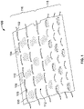
- the knitted component 100 includes at least one foamable yarn 102 when it is knitted and removed from a knitting machine. Additionally, the knitted component 100 may include a plurality of first yarns 104 that form a plurality of courses and/or a plurality of intermeshed loops of the knitted component 100 (e.g., where references to a "second yarn" refer to the foamable yarn 102).
- the first yarns 104 may be formed of a polyester material and/or another suitable material appreciated by those with skill in the art. The first yarns 104 may not be foamable yarns.
- a foamable yarn 102 is defined herein as a yarn that includes a foamable material, where the foamable material includes a thermoplastic polymer and a blowing agent.
- foamable yarns are described in U.S. Provisional Application No. 62/937,092, filed November 18, 2019 , and entitled "FOAMABLE YARNS, TEXTILES AND ARTICLES INCORPERATING FOAMABLE YARNS, AND THE PROCESS OF MANUFACTURING THE SAME,".
- thermoplastic material e.g., a thermoplastic polymer
- the thermoplastic polymer may comprise a natural polymeric material, a regenerated material, a synthetic polymeric material, or some combination thereof.
- the natural polymeric materials may be either plant-derived or animal- derived.
- Plant-derived natural polymeric materials may include cotton, flax, hemp, jute, or similar.
- Animal-derived natural polymeric materials may include spider silk, silkworm silk, sheep wool, alpaca wool, or similar.
- the regenerated material is created by dissolving the cellulose area of plant fiber in chemicals and making it into fiber again (by viscose method). Since it consists of cellulose like cotton and hemp, it is also called "regenerated cellulose fiber.”
- the regenerated material may include materials such a rayon and modal, among others.
- the synthetic polymeric material may include any of a variety of homopolymers or copolymers or a combination of homopolymers and copolymers.
- the thermoplastic polymer may comprise: a thermoplastic polyurethane homopolymer or copolymer; a thermoplastic polyethylene homopolymer or copolymer; a thermoplastic polypropylene homopolymer or copolymer; a thermoplastic polyester homopolymer or copolymer; a thermoplastic polyether homopolymer or copolymer, a thermoplastic polyamide homopolymer or copolymer; or any combination thereof.
- These may include homopolymers or copolumers of polyethylene terephtalates, ethylene-vinyl acetates, Nylons, such as Nylon 6, Nylon 11, or Nylon 6,6, among others.
- thermoplastic material comprises a thermosetting thermoplastic material.
- a thermosetting material may cure when exposed to specific thermosetting conditions at which point the thermosetting thermoplastic material undergoes a chemical change.
- a thermosetting material is uncured and, thus, may be thermoplastic.
- the cured thermosetting material has undergone a chemical change and is thermoset.
- the thermosetting conditions that trigger the thermosetting thermoplastic material to cure may include a specific temperature, an amount of UV light exposure, actinic radiation, microwave radiation, radiowave radiation, electron beam radiation, gamma beam radiation, infrared radiation, ultraviolet light, visible light, or a combination thereof, among other conditions.
- the thermosetting thermoplastic material further comprises a cross-linking agent.
- cross-linking agents are chemical products that chemically form bonds between two hydrocarbon chains. The reaction can be either exothermic or endothermic, depending on the cross-linking agent used.
- One skilled in the art would be able to select any number of appropriate cross-linking agents that would be compatible with the thermoplastic polymer and allow for cross-linking of the thermoplastic material under the desired processing conditions including temperature, pressure, UV light exposure, and the like.
- a suitable cross-linking agent comprises a homobifunctional cross-linking agent.
- Homobifunctional reagents consist of identical reactive groups on either end of a spacer arm.
- Examples of homobifunctional cross- linking agents include: dimethyl pimelimidate dihydrochloride, 3,3'-dithiodipropionic acid di(N-hydroxysuccinimide ester), suberic acid bis(3-sulfo-N-hydroxysuccinimide ester) sodium salt, among others.
- a suitable cross-linking agent comprises a heterobifunctional cross-linking agent.
- Heterobifunctional cross-linking agents have two distinct reactive groups, allowing for cross-linking reactions to progress in a controlled, two-step reaction. This can reduce the prevalence of dimers and oligomers while crosslinking.
- heterobifunctional cross-linking agents include: S-acetylthioglycolic acid N-hydroxysuccinimide ester, 5-azido-2-nitrobenzoic acid N-hydroxysuccinimide ester, 4-azidophenacyl bromide, bromoacetic acid N- hydroxysuccinimide ester, N-(3-Dimethylaminopropyl)-N'-ethylcarbodiimide hydrochloride, N-(3-Dimethylaminopropyl)-N'-ethylcarbodiimide hydrochloride, N-(3- dimethylaminopropyl)-N'-ethylcarbodiimide hydrochloride, N-(3- dimethylaminopropyl)-N'-ethylcarbodiimide hydrochloride, N-(3- dimethylaminopropyl)-N'-ethylcarbodiimide hydrochloride purum, N-
- the foamable material of the foamable yarn 102 further comprises a blowing agent.
- blowing agents are substances that decompose or vaporize at an activation temperature to produce quantities of gases or vapors. Accordingly, they can be categorized as either chemical or physical blowing agents.
- a chemical blowing agent is a compound which can release a gas at its activation temperature. Generally, this released gas does not chemically react with the thermoplastic polymer serving as the polymer matrix.
- the process of evolving gas from the blowing agent is usually exothermic; however, certain compounds that decompose through thermal dissociation, such as bicarbonates, evolve gas in a reversible and endothermic reaction.
- Chemical blowing agents can be further subcategorized as inorganic and organic agents. Inorganic blowing agents are used mainly in rubber technology but may be used in plastic applications to create additional cross-linking during the blowing process.
- a physical blowing agent is a compound which can phase transition to a gas when the temperature, pressure, or temperature and pressure are changed. At a given pressure, the temperature at which the physical blowing agent transitions to a gas is the activation temperature.
- Physical blowing agents include low-boiling-point hydrocarbons or supercritical fluids.
- blowing agent can influence foam quality, density, homogeneity, and the costs of the foamed product.
- the characteristic property of these compounds is their decomposition temperature, which determines their practical use as blowing agents for a given thermoplastic material and for its processing conditions.
- the thermoplastic material In order for the yarn to be able to form a stable foam, the thermoplastic material must be deformable or plastic at the activation temperature of the blowing agent. To that end, the thermoplastic-material deformation temperature may be lower than the blowing-agent activation temperature.
- thermoplastic-material deformation temperature is greater than 10 degrees Celsius below the blowing-agent activation temperature. In some embodiments, the thermoplastic-material deformation temperature is greater than 20 degrees Celsius below the blowing-agent activation temperature. In other embodiments, the first thermoplastic material 110 has a softening temperature from 50 degrees Celsius to 145 degrees Celsius.
- the chemical blowing agent has an activation temperature that is at least 5 degrees Celsius above a melting temperature of the first thermoplastic material. In other embodiments, the activation temperature of the blowing agent is at least 10 degrees Celsius above the melting temperature of the first thermoplastic material. In further embodiments, the activation temperature of the blowing agent is at least 20 degrees above the melting temperature of the first thermoplastic material.
- thermoplastic polymer properties that may be considered when selecting a chemical blowing agent include the following: affinity with the thermoplastic polymer, maximum production of gases; activation temperature at which the blowing agent evolves gas, rate of gas evolution, toxicity, corrosiveness, odor of decomposition products, effect of decomposition products on the color and other physicochemical properties of the thermoplastic polymer, cost, availability, stability against decomposition during storage, and others.
- the blowing agent comprises a chemical blowing agent.
- the chemical blowing agent comprises sodium bicarbonate, ammonium carbonate, ammonium bicarbonate, calcium azide, azodicarbonamide, hydrazocarbonamide, benzenesulfonyl hydrazide, dinitrosopentamethylene tetramine, toluenesulfonyl hydrazide, p,p'- oxybis(benzenesulfonylhydrazide), azobisisobutyronitrile, barium azodicarboxylate, or any combination thereof.
- the blowing agent comprises a physical blowing agent.
- a physical blowing agent In addition to partially halogenated fluorochlorohydrocarbons, hydrocarbons (e.g. isobutene and pentane) and inert gases, such as carbon dioxide or nitrogen, can serve as physical blowing agents.
- Inert gases offer many advantages, including, low environmentally harmful outputs, low gas consumption, increased foam volume per weight of blowing agent used, high cost-effectiveness, non-flammable, non-toxic, chemically inert, minimal or no residues left behind in the polymeric foam after processing. Additionally, carbon dioxide has the advantage of having a higher solubility in many thermoplastic polymers than other inert gases, such nitrogen.
- the blowing agent is present in the first thermoplastic material in an amount effective to foam the first thermoplastic material into a multicellular foam structure when the foamable yarn 102 is processed (as discussed in more detail below).
- the amount of blowing agent may be measured as the concentration of blowing agent by weight in the thermoplastic material.
- An amount of blowing agent is considered effective when activating the blowing results in at least a 10 percent increase in the volume of the thermoplastic material.
- blowing agents may comprise at least two chemical blowing agents, at least two physical blowing agents, or a combination of a physical blowing agent and a chemical blowing agent.
- Each blowing agent has an activation temperature at the given processing pressure. These activations temperatures may be the same or may differ.
- blowing agents with different activation temperatures, processing of a foamable yarn into a multicellular foam structure can take place over a larger operation window of temperatures. Additionally, by controlling the temperature to activate a first blowing agent and then increasing the temperature of the foamable yarn to activate the second blowing agent, a variety of different desirable foam structures can be achieved.
- two blowing agents may have activation temperatures that differ by at least 5 degrees Celsius.
- two blowing agents may have activation temperatures that differ by at least 10 degrees Celsius.
- two blowing agents may have activation temperatures that differ by at least 20 degrees Celsius.
- a wide range of additives may also be used in the foamable yarn 102.
- catalysts speed up the reaction or, in some cases, reduce the reaction initiation temperature.
- blowing agents that form gas bubbles in the polymer or polymerizing mixture produce foam.
- Surfactants may be added to control the size of bubbles.
- Other additives that may be used include cross-linking agents, chain-extending agents, fillers, flame retardants and coloring materials (such as dyes or pigments), ultraviolet light absorbers, antioxidants, lubricants, plasticizers, emulsifiers, rheology modifier, odorants, deodorants, or halogen scavenger, depending on the application.
- each formulation may be designed with the proper ingredients to achieve the desired properties of the final material.
- different blowing agents may require additional additives to maintain thermal properties.
- the density of the foam after the foamable yarn 102 is processed is determined by the number and size of the cells, which is affected, at least in part, by the amount of blowing that takes place during processing.
- the foamable yarn 102 may include a core having a material that is different from the foamable material.
- the core of the foamable yarn 102 may remain in substantially in-tact when subjected to an amount of heat for processing the yarn such that, even when the foamable material is softened due to its thermoplastic component being heated, the core of the foamable yarn 102 may retain structural integrity such that the core and/or the processing foamable material (and/or resulting foam) remains in a desirable location. Examples of core materials and structure are described in U.S. Provisional Application No. 62/937,092 .
- At least a portion of the foamable yarn 102 is inlaid between at least a first loop and a second loop of the plurality of knit loops within a first area of the knitted component 100 on a knitting machine during the manufacturing of the knitted component 100.
- the foamable yarn 102 may be inserted within a course of the knitted component during on a knitting machine, such as by utilizing an inlay process.
- an inlay process may include using an inlay feeder or other mechanical inlay device on a knitting machine (e.g., a combination feeder) to place the foamable yarn 102 between two needle beds (e.g., front and back needle beds) during a knitting process.
- certain portions of the foamable yarn 102 are exposed on an outer surface 112 of the knitted component 100.
- the knitted component 100 includes a first portion 106 of the foamable yarn 102 that is located on the surface 112 (e.g., such that it is accessible from an external perspective).
- a second portion 108, third portion 110, etc. may be exposed on the outer surface 112.
- the portion of the foamable yarn 102 between the first portion 106 and the second portion 108 (e.g., a depicted "covered portion 105") may be located beneath the outer surface 112 such that it is substantially covered by at least one loop of the first yarn 104.
- this exposure of the foamable yarn 102 may allow a foam protrusion and/or another foam surface characteristic to be formed on the surface 112 upon post-knit processing, for example.
- the portion of the foamable yarn 102 that remains beneath the surface 112 may be substantially protected from the processing stimulus (e.g., heat) since it is covered by loops of the knitted component 100.
- the covered portion of the foamable yarn 102 may still be at least partially processed (but, in certain embodiments, foam expansion may be limited by the surrounding knit structure, for example).
- Particular examples of knitting methods for exposing the first portion 106, second portion 108, etc. on the surface 112 are discussed below with reference to FIGS. 10 , 11 , 13 and 14 .
- multiple inlaid foamable yarns 102 may be included (e.g., extending substantially parallel as shown, or not).
- the different inlaid foamable yarns 102 may extend through different courses of the knitted component 100 formed by the first yarns 104. While the foamable yarns 102 are shown as being a consistent yarn type in FIG. 1 , it is contemplated that different types of foamable yarns 102 may be included.
- certain areas of the knitted component 100 may include a yarn with a relatively high density of the foamable material per unit length relative to other areas that are constructed similarly from a knitting perspective.
- certain exposed areas may have at least 10% more, at least 20% more, at least 30% more, at least 50% more, at least 75% more, at least 100% more, or even more than other exposed areas of the foamable yarns 102.
- certain areas may form foam protrusions of different sizes (as discussed below).
- the foam protrusions 212 may have a height of at least 2 mm, such as at least 5mm, 10mm, 20mm, or greater.
- the protrusions may be at least 2 mm in length and/or width, such as at least 5mm, 10mm, 20mm, or greater.
- a first area 116 of the knitted component 100 includes exposed portions that are longer than exposed portions in the second area 118.
- foam protrusions formed in the first area 116 will generally be larger in at least one dimension (e.g., at least longer) than foam protrusions formed in the second area 118 since more of the foamable material is exposed on the surface 112 in the first area 116 relative to the second area 118.
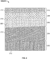
- FIG. 2 shows an example of an article 200, which may be initially formed as a knitted component in a manner similar to the knitted component 100 depicted by FIG. 1 .
- the article 200 may generally include five (5) regions.
- a first region 202 may include a plurality of foam protrusions 212.
- the foam protrusions 212 may include a multicellular foam formed as the reaction product of foaming the above-described foamable yarn 102, for example.
- the exposed portions 106, 108, etc. of FIG. 1 the exposed portions may be exposed to a particular amount of heat and/or another stimulus to activate the foamable material after the knitted component 100 of FIG. 1 is formed. Particular activation parameters are described in detail in U.S.
- the foamable material As the foamable material is activated, it may expand (e.g., away from the surface 112 of FIG. 1 ) and then set or harden in an expanded state as it is allowed cool (or otherwise obtain a relatively permanent material state).
- the resulting structures may be protrusions, such as the foam protrusions 212 that form a particular surface topography.
- the first region 202 may include protrusions 212 that are substantially the same size, but this is optional.
- the first region 202 may alternatively have variable amount of foamable material exposed on the surface of the knitted component, and/or may alter the processing procedure in different areas of the first region 202, such that the protrusions 212 vary.
- the protrusions 212 may form a surface pattern optimized for a certain function, for example.
- the second region 204 of FIG. 2 is similar to the first region 202, but the protrusions 212 are slightly smaller. This may be accomplished by either altering the knitting process (e.g., by exposing less of a foamable yarn inlay on a surface) and/or by switching types of the foamable yarn during knitting.
- the fourth region 208 and the fifth region 210 include protrusions 212 that are relatively spaced apart (e.g., by separating the exposed portions of the inlaid foamable yarns) and relatively low in height, respectively. A variety of additional and/or alternative patterns may be used. Further, while all of the protrusions 212 in FIG.
- the shape of the protrusions 212 could be altered by utilizing specific knit structures, specific material types, by using a mold press or other similar device during the foam activate step, or by any other suitable method.
- the third region 206 of FIG. 2 includes a foam surface 222 that is substantially formed of foam (e.g., the reaction product of the foamable yarn 102).
- the foam surface 222 may be formed via a variety of methods.
- the foamable material used in the foamable yarn may have a high enough concentration such that the foam fully covers the outer surface of the knitted component 100 once it is processed and embodies an expanded state.
- it is contemplated that most or all of the surface 222 may be formed of the foamable yarns 102 with less foam expansion (see, e.g., FIG. 12 and the associated description).
- FIG. 3-7 show various embodiments or details of embodiments of articles 200 formed using the methods and processes described herein.
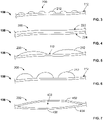
- FIG. 3 shows an article 200 having relatively small foam protrusions 212 that extend from the surface 112 of the knitted component 100.
- location between the foam protrusions 212 may include inlaid yarns having a foamable material (e.g., such that the foamable material, and/or a foam, extends through the knitted component 100 from one protrusion 212 to the next.
- the protrusions of FIG. 3 are substantially the same size, they may alternatively vary (e.g., due to using different yarns and/or by exposing different lengths of the yarns including the foamable material during knitting). While the foam protrusions 212 are shown only on one side of the fabric, they could additionally or alternatively be on the other side.
- FIG. 4 shows an article 200 having a foam surface 222, or a surface that is substantially covered with a multicellular foam.
- foam surface 222 may be formed by using a sufficient amount of foamable material within a yarn such that it substantially covers the knitted loops once it expands due to post-knit processing, for example.
- foam surface 222 is formed on only one side of the article 200 in the depicted embodiment, the opposite surface 224 may additionally or alternatively be covered in a foam (e.g., once the knitted component is processed such that the foamable yarn forms the foam).
- FIGS. 5-6 are similar to FIG. 3 , but the foam protrusions are different sizes.
- the foam protrusions 212 are about the same height as the foam protrusions 212 of FIG. 3 , but they are longer (e.g., due to foamable yarns being exposed for a longer distance).
- the foam protrusions are substantially taller than those of FIG. 3 or FIG. 5 . This may be accomplished by utilizing a foamable yarn having more of the foamable material per unit length, and or by processing the foamable yarn differently to achieve a relatively high degree of expansion.
- the knitted component of the claimed invention comprises a first area including a first yarn and a second yarn that includes a foamable material, wherein a first portion of the second yarn is exposed on a first surface in the first area.
- the first area optionally includes a tubular knit construction having a first layer and a second layer, wherein at least one of the first layer and the second layer includes the first yarn, and a portion of the second yarn used in the knitted component of the claim invention may be located within a pocket.
- FIG. 7 shows a detail of an embodiment, where a multicellular foam 400 is located between a first layer 402 and a second layer 404 of the knitted component 100.
- a foamable yarn (as described above) may be inlaid through an area having a tubular knit construction, where the first layer 402 and the second layer 404 are formed.
- the first layer 402 may comprise a plurality of courses formed by intermeshed loops (e.g., of the above-described "first yarn")
- the second layer 404 may comprise a plurality of courses formed by intermeshed loops.
- a pocket 408 may be formed between the first layer 402 and the second layer 404, particularly where the loops of the first layer 402 are not directly connected to (e.g., interlooped with) the loops of the second layer 404.
- the pocket 408 may exist even prior to post-knit processing, and the foamable yarn may be located therein due to the inlay procedure. Once heated or otherwise processed, the foamable material of the foamable yarn may expand to fill the pocket 408.
- Such an embodiment may be advantageous for providing a foam cushion within a knit structure, for example, although other functions and/or uses are additionally or alternatively contemplated.
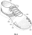
- FIG. 8 shows an upper 300 for an article of footwear that includes a plurality of foamable yarns 102.
- the upper 300 is shown in a pre- processed state in FIG. 8 (e.g., prior to forming the foam protrusions after the knitting process).
- the inlaid foamable yarns 102 may be exposed on an outer surface 320 of the upper 300 in select locations. Any suitable location may be chosen, such as in the midfoot area 324 and the toe area 326 in the depicted example (which is for illustration only).
- the foam protrusions, once formed, may provide suitable surface characteristics on the outer surface 320 of the upper 300.
- the foam protrusions may form gripping elements (e.g., suitable for kicking a soccer ball with a high degree of spin, for gripping a rope, rock wall, or other object during a particular athletic completion, etc.). If a relatively soft foam is used, it is also contemplated that the foamable yarns 102 may be exposed on an interior surface 328 of the upper 300 to provide cushioning and/or other comfort characteristics.
- gripping elements e.g., suitable for kicking a soccer ball with a high degree of spin, for gripping a rope, rock wall, or other object during a particular athletic completion, etc.
- the foamable yarns 102 may be exposed on an interior surface 328 of the upper 300 to provide cushioning and/or other comfort characteristics.
- FIG. 9 shows another embodiment of an upper 300, where the upper 300 is in a configuration that it may have just after knitting (and/or post-knit processing) but before being folded or otherwise manipulated into a wearable shape.
- the upper 300 may include multiple regions having different surface characteristics (e.g., similar to the embodiment of FIG. 2 ). The surface characteristics are formed by the foam protrusions 212, and/or the foam surface 222.
- the upper may include a first region 306 with a set of foam protrusions 212 covering the toe area 326.
- a second region 308, located in the midfoot area 324 of the upper, may include larger foam protrusion 212.
- a third region 310 may include a surface that is substantially formed of a multicellular foam (as discussed above), which may be advantageous for providing cushioning where a fastening system is located (e.g., where shoelaces are tightened over the throat area 332 of the upper 300, for example).
- the heel area 330 includes a fourth region 312 with relatively small foam protrusions 212. Notably, certain areas may lack protrusion, the regions may be reorganized, etc.
- FIGS. 10 , 11 and13 show certain examples of knitting techniques that may be used to expose certain portions of an inlaid foamable yarn on a surface of a knitted component.
- an inlay jacquard procedure may be used to inlay a foamable yarn 102 within loops of a first yarn 104 (e.g., comprising a polyester and elastane in the depicted embodiment, though other suitable yarn types are also contemplated).
- a unique transfer process T may be utilized, which is key to ensuring that a length of the foamable yarn 102 will be exposed on a resulting surface.
- the transfer T causes certain loops of a course that would otherwise cover the foamable yarn 102 (e.g., where it is eventually exposed) to move to an opposite needle bed, thereby providing a hole or an "opening" where a plurality of needles are skipped on one needle bed (e.g., such that nothing covers the inlaid foamable yarn 102).
- the resulting exposed length of the foamable yarn 102 may be equal to or greater than the length of a portion of a knitted course comprising at least two consecutive loops, for example, and perhaps much larger (e.g., at least three, four, five, ten, fifteen, or even twenty or more consecutive loops). In metric units, this exposed length may be equal to at least 2 mm, for example, and potentially much larger (e.g., equal to or greater than 5 mm, 10 mm, 20 mm, or more).
- the process of FIG. 10 may correspond to the first region 202 of FIG. 2 , for example.
- the knitted component of the claimed invention comprises a first area, including a first yarn (104) and a second yarn (102), wherein the second yarn (102) is a foamable yarn.
- a fusible yarn 140 may additionally be included, which may cover and then "release" certain portions of the foamable yarn 102, for example (as described with reference to FIG. 12 ).
- the fusible yarn 140 may additionally be included to provide rigidity, strength, and/or other advantageous features to the knitted component once processed with heat (which may be the same heat used to activate the foamable yarn, for example).
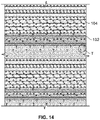
- FIGS. 11 and 13-14 show processes that may form similar knit structures to the structure formed by FIG. 10 , for example, and the general principle used to form exposed portions of the foamable yarn 102 remains the same (e.g., by utilizing a transfer T).
- FIGS. 11 and 13-14 may correspond to the regions 204, 208, and 210, of FIG. 2 , respectively.
- other yarns may be included, such as a high tenacity yarn 103 shown in FIG. 11 , which may provide a high degree of strength and rigidity.
- FIG. 12 illustrates a knitting structure that may be obtained when forming a surface fully or substantially formed by a foam in the knitted component of the claimed invention (e.g., once processed).
- the foamable yarn 102 is inlaid between courses formed by a first yarn 104 (e.g., a polyester or other high-melting-point yarn, potentially including an elastane, for example) and a fusible yarn 140 (e.g., formed of a thermoplastic material having a relatively low melting point suitable for heat processing).
- a first yarn 104 e.g., a polyester or other high-melting-point yarn, potentially including an elastane, for example
- a fusible yarn 140 e.g., formed of a thermoplastic material having a relatively low melting point suitable for heat processing.
- the only loops formed on the front side of the inlaid foamable yarn 102 are formed solely of the fusible yarn 140.
- the resulting knitting component may appear similar to other knitted components described using the knit processes depicted above.
- the fusible yarn 140 may substantially or fully melt, thereby allowing the foamable material of the foamable yarn 102 to "release" due to deformation of the fusible yarn 140.
- the foamable material may substantially or wholly cover the respective side of the fabric, thereby forming a foam surface similar to as described above (see, e.g., the third region 206 of FIG. 2 and the third region 310 of FIG. 9 ).
- the present invention provides a knitted component, comprising a first area, wherein the first area includes a plurality of knit loops comprising a first yarn; and a second yarn at least partially inlaid within the first area of the knitted component such that the second yarn extends between at least a first loop and a second loop of the plurality of knit loops, wherein the second yarn is a foamable yarn that includes a foamable material comprising a blowing agent and a thermoplastic polymer and a first portion of the second yarn is exposed on a first surface in the first area.
- the first portion has a length that is greater than or equal to the length of a portion of a first course that includes at least three consecutive knit loops, the first course being in the first area.
- the second yarn additionally includes a second portion that is exposed on the first surface in the first area, and wherein the second yarn includes a covered portion extending from the first portion to the second portion.
- a length of the second portion is larger than a length of the first portion.
- a second course extends through a second area with a second surface, wherein the second yarn is at least partially inlaid within the second course, and wherein the second yarn includes a second portion that is exposed on the second surface in the second area.
- the second portion of the second yarn includes a length that is larger than a length of the first portion of the second yarn.
- the first area includes a tubular knit construction having a first layer and a second layer, wherein at least one of the first layer and the second layer includes the first yarn, and wherein at least a portion of the second yarn is located within a pocket between the first layer and the second layer.
- the knitted component may further comprise a third yarn that is included in at least one loop of a first course, wherein the third yarn includes a second thermoplastic polymer, and where the second thermoplastic polymer has a melting temperature of 120 C or less.
- a knitted component may comprise: a first area having a first surface, wherein the first area is at least partially formed by a first knit course, the first knit course having a plurality of loops formed by a first yarn; and a multicellular foam material at least partially surrounding the first yarn in in the first area of the knitted component, wherein the multicellular foam material forms a first protrusion extending from the first surface of the first area.
- the at least one protrusion includes a height of at least 2 mm.
- the multicellular foam material is the reaction product of foaming at least a portion of a second yarn, the second yarn comprising a first thermoplastic material.
- the at least one protrusion has a length that is at least 5 mm.
- the at least one protrusion includes a first foam protrusion and a second foam protrusion, and wherein the second foam protrusion includes at least 20% more of the multicellular foam material, by mass, than the first foam protrusion.
- the at least one protrusion includes a first foam protrusion and a second foam protrusion, and wherein a covered portion of a second yarn extends from the first foam protrusion to the second foam protrusion, the covered portion including at least one of the multicellular foam material and a foamable material with a blowing agent.
- the covered portion of the second yarn is inlaid through the knitted component.
- the knitted component may further comprise a third yarn that is included in at least one loop of the first knit course, wherein the third yarn includes a second thermoplastic polymer material, and wherein the second thermoplastic polymer material having a melting temperature of 120 C or less.
- the present invention further provides a method of preparing the knitted component, comprising: knitting a course with a first yarn, wherein the course comprises a plurality of loops; inlaying a second yarn at least partially within the first course, wherein the second yarn is a foamable yarn that includes a foamable material comprising a blowing agent and a thermoplastic polymer; and transferring a loop of the first course from one needle bed to another needle bed such that at least a portion of the foamable yarn is exposed on a surface of a resulting knitted component.
- the method may further comprise heating the knitted component such that the foamable yarn forms at least one foam protrusion on a surface of the knitted component.
- the method may further comprise knitting at least one loop with a fusible yarn that is separate from the foamable yarn, and further comprising heating the fusible yarn such that the fusible yarn deforms when a foamable material of the foamable yarn expands.
Landscapes
- Engineering & Computer Science (AREA)
- Textile Engineering (AREA)
- Chemical & Material Sciences (AREA)
- Chemical Kinetics & Catalysis (AREA)
- Mechanical Engineering (AREA)
- Materials Engineering (AREA)
- Botany (AREA)
- Life Sciences & Earth Sciences (AREA)
- Manufacturing & Machinery (AREA)
- General Chemical & Material Sciences (AREA)
- Composite Materials (AREA)
- Knitting Of Fabric (AREA)
- Laminated Bodies (AREA)
Description
- The present disclosure relates generally to knitted components and methods of manufacturing knitted components, for example, knitted components for use in footwear applications, apparel applications, or the like.
- A variety of articles are formed from textiles. As examples, articles of apparel (e.g., shirts, pants, socks, footwear, jackets and other outerwear, briefs and other undergarments, hats and other headwear), containers (e.g., backpacks, bags), and upholstery for furniture (e.g., chairs, couches, car seats) are often at least partially formed from textiles. These textiles are often formed by weaving or interlooping (e.g., knitting) a yarn or a plurality of yarns, usually through a mechanical process involving looms or knitting machines. One particular object that may be formed from a textile is an upper for an article of footwear.
- Knitting is an example of a process that may form a textile. Knitting may generally be classified as either weft knitting or warp knitting. In both weft knitting and warp knitting, one or more yarns are manipulated to form a plurality of intermeshed loops that define a variety of courses and wales. In weft knitting, which is more common, the courses and wales are perpendicular to each other and may be formed from a single yarn or many yarns. In warp knitting, the wales and courses run roughly parallel.
- Although knitting may be performed by hand, the commercial manufacture of knitted components is generally performed by knitting machines. An example of a knitting machine for producing a weft knitted component is a V-bed flat knitting machine, which includes two needle beds that are angled with respect to each other. Rails extend above and parallel to the needle beds and provide attachment points for feeders, which move along the needle beds and supply yarns to needles within the needle beds. Standard feeders have the ability to supply a yarn that is utilized to knit, tuck, and float. In situations where an inlay yarn is incorporated into a knitted component, an inlay feeder is typically utilized.
EP 2530195 A1 discloses a knitted/woven fabric comprising non-meshed intermediate layer made of jersey fabric which is inserted between the upper and lower layers of the fabric.FR 1176314 A US 2019/037967 discloses a knitting component comprising a pod having a first surface formed by a first yarn and a second surface formed by a second yarn; and an edge region having a first surface formed by the second yarn and a second surface. - The embodiments of the present disclosure may be better understood with reference to the following drawings and description. The components in the FIG.s are not necessarily to scale, with emphasis instead being placed upon illustrating the principles of the present disclosure. Moreover, in the figures, like referenced numerals designate similar or identical features in certain instances.
-
FIG. 1 is an illustration showing a knitted component including an inlaid foamable yarn in accordance with certain aspects of the present disclosure. -
FIG. 2 is an illustration showing an article having a knitted component with foam protrusions extending from a surface. -
FIG. 3 is an illustration showing an article having a knitted component with foam protrusions extending from a surface thereof. -
FIG. 4 is an illustration showing an article having a knitted component and a foam surface. -
FIG. 5 is an illustration showing an article having a knitted component with foam protrusions extending from a surface thereof. -
FIG. 6 is an illustration showing an article having a knitted component with foam protrusions extending from a surface thereof. -
FIG. 7 is an illustration showing a detail of an article having a knitted component with a tubular knit structure forming a pocket along with a foamed interior of the pocket, wherein at least a portion of the second yarn (i.e. foamable yarn) is located in the pocket. -
FIG. 8 is an illustration showing an upper for an article of footwear having an inlaid foamable yarn. -
FIG. 9 is an illustration showing an upper for an article of footwear having a knitted component and foam protrusions extending from a surface thereof. -
FIGS. 10 ,11 ,13 and14 are illustrations showing knit diagrams for forming a knitted component having an inlaid foamable yarn.FIG. 12 is an illustration showing a knitted component together with an additional fusible yarn. - The present invention provides a knitted component as defined in claim 1 and a method of preparing the knitted component as defined in claim 9. Preferred embodiments are set out in the dependent claims. Various aspects are described below with reference to the drawings in which like elements generally are identified by like numerals. The relationship and functioning of the various elements of the aspects may better be understood by reference to the following detailed description. However, aspects are not limited to those illustrated in the drawings or explicitly described below. It also should be understood that the drawings are not necessarily to scale, and in certain instances details may have been omitted that are not necessary for an understanding of aspects disclosed herein, such as conventional fabrication and assembly.
- A textile may be defined as a structure manufactured from fibers, filaments, or yarns characterized by flexibility, fineness, and a high ratio of length to thickness. Textiles generally fall into two categories. The first category includes textiles produced directly from webs of filaments or fibers by randomly (or non-randomly) interlocking or interconnecting to construct non-woven fabrics and felts. The second category includes textiles formed through a mechanical manipulation of yarn(s) (e.g., by interlacing or interlooping), thereby producing a woven fabric or a knitting fabric, for example.
- Textiles may include one or more yarns. In general, a yarn is defined as an assembly having a substantial length and relatively small cross-section that is formed of at least one filament or a plurality of fibers. Fibers have a relatively short length and require spinning or twisting processes to produce a yarn of suitable length for use in textiles. Common examples of fibers are cotton and wool. Filaments, however, have an indefinite length and may merely be combined with other filaments to produce a yarn suitable for use in textiles. Modern filaments include a plurality of synthetic materials such as rayon, nylon, polyester, and polyacrylic, with silk being the primary, naturally-occurring exception. Yarn may be formed of a single filament, which is conventionally referred to as a "monofilament yarn," or a plurality of individual filaments grouped together. Yarn may also include separate filaments formed of different materials, or the yarn may include filaments that are each formed of two or more different materials. Similar concepts also apply to yarns formed from fibers. Accordingly, yarns may have a variety of configurations that generally conform to the definition provided above.
- The following description relates to knitted textiles, or "knitted components." For example, referring to
Fig.1 , certain articles may be at least partially formed as, and potentially fully formed as, a knittedcomponent 100. Advantageously, forming articles that include a knittedcomponent 100 may impart advantageous characteristics including, but not limited to, a particular degree of elasticity (for example, as expressed in terms of Young's modulus), breathability, bendability, strength, moisture absorption, weight, abrasion resistance, and/or a combination thereof. These characteristics may be accomplished by selecting a particular single layer or multi-layer knit structure (e.g., a ribbed knit structure, a single jersey knit structure, or a double jersey knit structure), by varying the size and tension of the knit structure, by using one or more yarns formed of a particular material (e.g., a polyester material, a relatively inelastic material, or a relatively elastic material such as spandex), by selecting yarns of a particular size (e.g., denier), and/or a combination thereof. The weight of the article (e.g., such as an upper 300 as shown inFIG. 8 , and thus the overall weight of the article of footwear), may be reduced with respect to alternative articles (e.g., traditional non-knitted uppers and/or other components that are typically used in footwear). The knittedcomponent 100 may also provide desirable aesthetic characteristics by incorporating yarns having different colors, textures or other visual properties arranged in a particular pattern. The yarns themselves and/or the knit structure formed by one or more of the yarns of the knitted components may be varied at different locations to provide different knit portions with different properties. - Referring to
FIG. 1 , the knittedcomponent 100 includes at least onefoamable yarn 102 when it is knitted and removed from a knitting machine. Additionally, the knittedcomponent 100 may include a plurality offirst yarns 104 that form a plurality of courses and/or a plurality of intermeshed loops of the knitted component 100 (e.g., where references to a "second yarn" refer to the foamable yarn 102). For example, thefirst yarns 104 may be formed of a polyester material and/or another suitable material appreciated by those with skill in the art. Thefirst yarns 104 may not be foamable yarns. Herein, afoamable yarn 102 is defined herein as a yarn that includes a foamable material, where the foamable material includes a thermoplastic polymer and a blowing agent. Examples of foamable yarns are described inU.S. Provisional Application No. 62/937,092, filed November 18, 2019 - As described herein, a thermoplastic material (e.g., a thermoplastic polymer) is a substance that may become plastic on heating and hardens when cooling without undergoing a chemical transformation. The thermoplastic polymer may comprise a natural polymeric material, a regenerated material, a synthetic polymeric material, or some combination thereof.
- The natural polymeric materials may be either plant-derived or animal- derived. Plant-derived natural polymeric materials may include cotton, flax, hemp, jute, or similar. Animal-derived natural polymeric materials may include spider silk, silkworm silk, sheep wool, alpaca wool, or similar. The regenerated material is created by dissolving the cellulose area of plant fiber in chemicals and making it into fiber again (by viscose method). Since it consists of cellulose like cotton and hemp, it is also called "regenerated cellulose fiber." The regenerated material may include materials such a rayon and modal, among others.
- The synthetic polymeric material may include any of a variety of homopolymers or copolymers or a combination of homopolymers and copolymers. For instance, the thermoplastic polymer may comprise: a thermoplastic polyurethane homopolymer or copolymer; a thermoplastic polyethylene homopolymer or copolymer; a thermoplastic polypropylene homopolymer or copolymer; a thermoplastic polyester homopolymer or copolymer; a thermoplastic polyether homopolymer or copolymer, a thermoplastic polyamide homopolymer or copolymer; or any combination thereof. These may include homopolymers or copolumers of polyethylene terephtalates, ethylene-vinyl acetates, Nylons, such as Nylon 6, Nylon 11, or Nylon 6,6, among others.
- Additionally, in other embodiments the thermoplastic material comprises a thermosetting thermoplastic material. As described herein, a thermosetting material may cure when exposed to specific thermosetting conditions at which point the thermosetting thermoplastic material undergoes a chemical change. A thermosetting material is uncured and, thus, may be thermoplastic. The cured thermosetting material has undergone a chemical change and is thermoset. The thermosetting conditions that trigger the thermosetting thermoplastic material to cure may include a specific temperature, an amount of UV light exposure, actinic radiation, microwave radiation, radiowave radiation, electron beam radiation, gamma beam radiation, infrared radiation, ultraviolet light, visible light, or a combination thereof, among other conditions.
- In some embodiments, the thermosetting thermoplastic material further comprises a cross-linking agent. As understood in the art, cross-linking agents are chemical products that chemically form bonds between two hydrocarbon chains. The reaction can be either exothermic or endothermic, depending on the cross-linking agent used. One skilled in the art would be able to select any number of appropriate cross-linking agents that would be compatible with the thermoplastic polymer and allow for cross-linking of the thermoplastic material under the desired processing conditions including temperature, pressure, UV light exposure, and the like.
- In some instances a suitable cross-linking agent comprises a homobifunctional cross-linking agent. Homobifunctional reagents consist of identical reactive groups on either end of a spacer arm. Examples of homobifunctional cross- linking agents include: dimethyl pimelimidate dihydrochloride, 3,3'-dithiodipropionic acid di(N-hydroxysuccinimide ester), suberic acid bis(3-sulfo-N-hydroxysuccinimide ester) sodium salt, among others.
- In other instances, a suitable cross-linking agent comprises a heterobifunctional cross-linking agent. Heterobifunctional cross-linking agents have two distinct reactive groups, allowing for cross-linking reactions to progress in a controlled, two-step reaction. This can reduce the prevalence of dimers and oligomers while crosslinking. Examples of heterobifunctional cross-linking agents include: S-acetylthioglycolic acid N-hydroxysuccinimide ester, 5-azido-2-nitrobenzoic acid N-hydroxysuccinimide ester, 4-azidophenacyl bromide, bromoacetic acid N- hydroxysuccinimide ester, N-(3-Dimethylaminopropyl)-N'-ethylcarbodiimide hydrochloride, N-(3-Dimethylaminopropyl)-N'-ethylcarbodiimide hydrochloride, N-(3- dimethylaminopropyl)-N'-ethylcarbodiimide hydrochloride, N-(3- dimethylaminopropyl)-N'-ethylcarbodiimide hydrochloride purum, N-(3-dimethylaminopropyl)-N'-ethylcarbodiimide hydrochloride, iodoacetic acid N-hydroxysuccinimide ester powder, among others.
- The foamable material of the
foamable yarn 102 further comprises a blowing agent. As understood in the art, blowing agents are substances that decompose or vaporize at an activation temperature to produce quantities of gases or vapors. Accordingly, they can be categorized as either chemical or physical blowing agents. A chemical blowing agent is a compound which can release a gas at its activation temperature. Generally, this released gas does not chemically react with the thermoplastic polymer serving as the polymer matrix. The process of evolving gas from the blowing agent is usually exothermic; however, certain compounds that decompose through thermal dissociation, such as bicarbonates, evolve gas in a reversible and endothermic reaction. Chemical blowing agents can be further subcategorized as inorganic and organic agents. Inorganic blowing agents are used mainly in rubber technology but may be used in plastic applications to create additional cross-linking during the blowing process. - A physical blowing agent is a compound which can phase transition to a gas when the temperature, pressure, or temperature and pressure are changed. At a given pressure, the temperature at which the physical blowing agent transitions to a gas is the activation temperature. Physical blowing agents include low-boiling-point hydrocarbons or supercritical fluids.
- The choice of blowing agent can influence foam quality, density, homogeneity, and the costs of the foamed product. As discussed below, the characteristic property of these compounds is their decomposition temperature, which determines their practical use as blowing agents for a given thermoplastic material and for its processing conditions. In order for the yarn to be able to form a stable foam, the thermoplastic material must be deformable or plastic at the activation temperature of the blowing agent. To that end, the thermoplastic-material deformation temperature may be lower than the blowing-agent activation temperature.
- In some embodiments, the thermoplastic-material deformation temperature is greater than 10 degrees Celsius below the blowing-agent activation temperature. In some embodiments, the thermoplastic-material deformation temperature is greater than 20 degrees Celsius below the blowing-agent activation temperature. In other embodiments, the first
thermoplastic material 110 has a softening temperature from 50 degrees Celsius to 145 degrees Celsius. - In some embodiments, the chemical blowing agent has an activation temperature that is at least 5 degrees Celsius above a melting temperature of the first thermoplastic material. In other embodiments, the activation temperature of the blowing agent is at least 10 degrees Celsius above the melting temperature of the first thermoplastic material. In further embodiments, the activation temperature of the blowing agent is at least 20 degrees above the melting temperature of the first thermoplastic material.
- Other properties that may be considered when selecting a chemical blowing agent include the following: affinity with the thermoplastic polymer, maximum production of gases; activation temperature at which the blowing agent evolves gas, rate of gas evolution, toxicity, corrosiveness, odor of decomposition products, effect of decomposition products on the color and other physicochemical properties of the thermoplastic polymer, cost, availability, stability against decomposition during storage, and others.
- In some embodiments, the blowing agent comprises a chemical blowing agent. In some embodiments, the chemical blowing agent comprises sodium bicarbonate, ammonium carbonate, ammonium bicarbonate, calcium azide, azodicarbonamide, hydrazocarbonamide, benzenesulfonyl hydrazide, dinitrosopentamethylene tetramine, toluenesulfonyl hydrazide, p,p'- oxybis(benzenesulfonylhydrazide), azobisisobutyronitrile, barium azodicarboxylate, or any combination thereof.
- In some embodiments, the blowing agent comprises a physical blowing agent. In addition to partially halogenated fluorochlorohydrocarbons, hydrocarbons (e.g. isobutene and pentane) and inert gases, such as carbon dioxide or nitrogen, can serve as physical blowing agents. Inert gases offer many advantages, including, low environmentally harmful outputs, low gas consumption, increased foam volume per weight of blowing agent used, high cost-effectiveness, non-flammable, non-toxic, chemically inert, minimal or no residues left behind in the polymeric foam after processing. Additionally, carbon dioxide has the advantage of having a higher solubility in many thermoplastic polymers than other inert gases, such nitrogen.
- In some embodiments, the blowing agent is present in the first thermoplastic material in an amount effective to foam the first thermoplastic material into a multicellular foam structure when the
foamable yarn 102 is processed (as discussed in more detail below). The amount of blowing agent may be measured as the concentration of blowing agent by weight in the thermoplastic material. An amount of blowing agent is considered effective when activating the blowing results in at least a 10 percent increase in the volume of the thermoplastic material. - In some embodiments, more than one blowing agent may be used. The combination of blowing agents may comprise at least two chemical blowing agents, at least two physical blowing agents, or a combination of a physical blowing agent and a chemical blowing agent. Each blowing agent has an activation temperature at the given processing pressure. These activations temperatures may be the same or may differ. By utilizing blowing agents with different activation temperatures, processing of a foamable yarn into a multicellular foam structure can take place over a larger operation window of temperatures. Additionally, by controlling the temperature to activate a first blowing agent and then increasing the temperature of the foamable yarn to activate the second blowing agent, a variety of different desirable foam structures can be achieved. In some embodiments, two blowing agents may have activation temperatures that differ by at least 5 degrees Celsius. In some embodiments, two blowing agents may have activation temperatures that differ by at least 10 degrees Celsius. In some embodiments, two blowing agents may have activation temperatures that differ by at least 20 degrees Celsius.
- A wide range of additives may also be used in the
foamable yarn 102. For example, catalysts speed up the reaction or, in some cases, reduce the reaction initiation temperature. As discussed above, blowing agents that form gas bubbles in the polymer or polymerizing mixture produce foam. Surfactants may be added to control the size of bubbles. Other additives that may be used include cross-linking agents, chain-extending agents, fillers, flame retardants and coloring materials (such as dyes or pigments), ultraviolet light absorbers, antioxidants, lubricants, plasticizers, emulsifiers, rheology modifier, odorants, deodorants, or halogen scavenger, depending on the application. - The molecular structure, amount, and reaction temperature of each ingredient determine the characteristics and subsequent use of the
foamable yarn 102 after processing. Therefore, each formulation may be designed with the proper ingredients to achieve the desired properties of the final material. By way of an example, different blowing agents may require additional additives to maintain thermal properties. Ultimately, the density of the foam after thefoamable yarn 102 is processed is determined by the number and size of the cells, which is affected, at least in part, by the amount of blowing that takes place during processing. By mixing different combinations of the starting materials, the rates of the reactions and overall rate of cure during processing can be controlled. - In some embodiments, the
foamable yarn 102 may include a core having a material that is different from the foamable material. Advantageously, the core of thefoamable yarn 102 may remain in substantially in-tact when subjected to an amount of heat for processing the yarn such that, even when the foamable material is softened due to its thermoplastic component being heated, the core of thefoamable yarn 102 may retain structural integrity such that the core and/or the processing foamable material (and/or resulting foam) remains in a desirable location. Examples of core materials and structure are described inU.S. Provisional Application No. 62/937,092 - At least a portion of the
foamable yarn 102 is inlaid between at least a first loop and a second loop of the plurality of knit loops within a first area of the knittedcomponent 100 on a knitting machine during the manufacturing of the knittedcomponent 100. For example, thefoamable yarn 102 may be inserted within a course of the knitted component during on a knitting machine, such as by utilizing an inlay process. For example, an inlay process may include using an inlay feeder or other mechanical inlay device on a knitting machine (e.g., a combination feeder) to place thefoamable yarn 102 between two needle beds (e.g., front and back needle beds) during a knitting process. One example of an inlay process, along with a combination feeder for enabling such a process, is described inU.S. Patent Application Publication No. 2013/0145652, published Jun 13, 2013, and having an applicant of NIKE, Inc. . Further, while not shown, it is contemplated that the foamable yarn may be included in at least one of the loops forming the courses of the knittedcomponent 100. - Still referring to
FIG. 1 , in some embodiments, certain portions of thefoamable yarn 102 are exposed on anouter surface 112 of the knittedcomponent 100. Theknitted component 100 includes afirst portion 106 of thefoamable yarn 102 that is located on the surface 112 (e.g., such that it is accessible from an external perspective). Similarly, asecond portion 108,third portion 110, etc. may be exposed on theouter surface 112. The portion of thefoamable yarn 102 between thefirst portion 106 and the second portion 108 (e.g., a depicted "coveredportion 105") may be located beneath theouter surface 112 such that it is substantially covered by at least one loop of thefirst yarn 104. Advantageously, and as described in more detail below, this exposure of thefoamable yarn 102 may allow a foam protrusion and/or another foam surface characteristic to be formed on thesurface 112 upon post-knit processing, for example. In some applications, the portion of thefoamable yarn 102 that remains beneath thesurface 112 may be substantially protected from the processing stimulus (e.g., heat) since it is covered by loops of the knittedcomponent 100. However, the covered portion of thefoamable yarn 102 may still be at least partially processed (but, in certain embodiments, foam expansion may be limited by the surrounding knit structure, for example). Particular examples of knitting methods for exposing thefirst portion 106,second portion 108, etc. on thesurface 112 are discussed below with reference toFIGS. 10 ,11 ,13 and14 . - Still referring to
FIG. 1 , multiple inlaidfoamable yarns 102 may be included (e.g., extending substantially parallel as shown, or not). For example, the different inlaidfoamable yarns 102 may extend through different courses of the knittedcomponent 100 formed by thefirst yarns 104. While thefoamable yarns 102 are shown as being a consistent yarn type inFIG. 1 , it is contemplated that different types offoamable yarns 102 may be included. For example, certain areas of the knittedcomponent 100 may include a yarn with a relatively high density of the foamable material per unit length relative to other areas that are constructed similarly from a knitting perspective. For example, certain exposed areas (and, the result protrusions) may have at least 10% more, at least 20% more, at least 30% more, at least 50% more, at least 75% more, at least 100% more, or even more than other exposed areas of thefoamable yarns 102. As a result, certain areas may form foam protrusions of different sizes (as discussed below). For example, thefoam protrusions 212 may have a height of at least 2 mm, such as at least 5mm, 10mm, 20mm, or greater. Regarding length and width, the protrusions may be at least 2 mm in length and/or width, such as at least 5mm, 10mm, 20mm, or greater. - Additionally or alternatively, it is contemplated that different knitting techniques may be used to control the amount of surface exposure of the
foamable yarns 102. InFIG. 1 , for example, afirst area 116 of the knittedcomponent 100 includes exposed portions that are longer than exposed portions in thesecond area 118. Once processed, foam protrusions formed in thefirst area 116 will generally be larger in at least one dimension (e.g., at least longer) than foam protrusions formed in thesecond area 118 since more of the foamable material is exposed on thesurface 112 in thefirst area 116 relative to thesecond area 118. -
FIG. 2 shows an example of anarticle 200, which may be initially formed as a knitted component in a manner similar to the knittedcomponent 100 depicted byFIG. 1 . Referring toFIG. 2 , thearticle 200 may generally include five (5) regions. Afirst region 202 may include a plurality offoam protrusions 212. The foam protrusions 212 may include a multicellular foam formed as the reaction product of foaming the above-describedfoamable yarn 102, for example. In particular, referring to the exposedportions FIG. 1 , the exposed portions may be exposed to a particular amount of heat and/or another stimulus to activate the foamable material after theknitted component 100 ofFIG. 1 is formed. Particular activation parameters are described in detail inU.S. Provisional Application No. 62/937,092 surface 112 ofFIG. 1 ) and then set or harden in an expanded state as it is allowed cool (or otherwise obtain a relatively permanent material state). The resulting structures may be protrusions, such as thefoam protrusions 212 that form a particular surface topography. - As shown in
FIG. 2 , thefirst region 202 may includeprotrusions 212 that are substantially the same size, but this is optional. Thefirst region 202 may alternatively have variable amount of foamable material exposed on the surface of the knitted component, and/or may alter the processing procedure in different areas of thefirst region 202, such that theprotrusions 212 vary. Theprotrusions 212 may form a surface pattern optimized for a certain function, for example. - The
second region 204 ofFIG. 2 is similar to thefirst region 202, but theprotrusions 212 are slightly smaller. This may be accomplished by either altering the knitting process (e.g., by exposing less of a foamable yarn inlay on a surface) and/or by switching types of the foamable yarn during knitting. Similarly, thefourth region 208 and thefifth region 210 includeprotrusions 212 that are relatively spaced apart (e.g., by separating the exposed portions of the inlaid foamable yarns) and relatively low in height, respectively. A variety of additional and/or alternative patterns may be used. Further, while all of theprotrusions 212 inFIG. 2 are substantially hemispherical in shape, it is contemplated that the shape of theprotrusions 212 could be altered by utilizing specific knit structures, specific material types, by using a mold press or other similar device during the foam activate step, or by any other suitable method. - The
third region 206 ofFIG. 2 includes afoam surface 222 that is substantially formed of foam (e.g., the reaction product of the foamable yarn 102). Thefoam surface 222 may be formed via a variety of methods. For example, the foamable material used in the foamable yarn may have a high enough concentration such that the foam fully covers the outer surface of the knittedcomponent 100 once it is processed and embodies an expanded state. Alternatively, and as discussed in more detail below, it is contemplated that most or all of thesurface 222 may be formed of thefoamable yarns 102 with less foam expansion (see, e.g.,FIG. 12 and the associated description). -
FIG. 3-7 show various embodiments or details of embodiments ofarticles 200 formed using the methods and processes described herein. For example,FIG. 3 shows anarticle 200 having relativelysmall foam protrusions 212 that extend from thesurface 112 of the knittedcomponent 100. As discussed above, location between thefoam protrusions 212 may include inlaid yarns having a foamable material (e.g., such that the foamable material, and/or a foam, extends through the knittedcomponent 100 from oneprotrusion 212 to the next. While the protrusions ofFIG. 3 are substantially the same size, they may alternatively vary (e.g., due to using different yarns and/or by exposing different lengths of the yarns including the foamable material during knitting). While thefoam protrusions 212 are shown only on one side of the fabric, they could additionally or alternatively be on the other side. -
FIG. 4 shows anarticle 200 having afoam surface 222, or a surface that is substantially covered with a multicellular foam. Such an embodiment may be formed by using a sufficient amount of foamable material within a yarn such that it substantially covers the knitted loops once it expands due to post-knit processing, for example. While thefoam surface 222 is formed on only one side of thearticle 200 in the depicted embodiment, theopposite surface 224 may additionally or alternatively be covered in a foam (e.g., once the knitted component is processed such that the foamable yarn forms the foam). -
FIGS. 5-6 are similar toFIG. 3 , but the foam protrusions are different sizes. For example, inFIG. 5 , thefoam protrusions 212 are about the same height as thefoam protrusions 212 ofFIG. 3 , but they are longer (e.g., due to foamable yarns being exposed for a longer distance). InFIG. 6 , the foam protrusions are substantially taller than those ofFIG. 3 or FIG. 5 . This may be accomplished by utilizing a foamable yarn having more of the foamable material per unit length, and or by processing the foamable yarn differently to achieve a relatively high degree of expansion. - The knitted component of the claimed invention comprises a first area including a first yarn and a second yarn that includes a foamable material, wherein a first portion of the second yarn is exposed on a first surface in the first area. The first area optionally includes a tubular knit construction having a first layer and a second layer, wherein at least one of the first layer and the second layer includes the first yarn, and a portion of the second yarn used in the knitted component of the claim invention may be located within a pocket.
FIG. 7 shows a detail of an embodiment, where amulticellular foam 400 is located between afirst layer 402 and asecond layer 404 of the knittedcomponent 100. For example, a foamable yarn (as described above) may be inlaid through an area having a tubular knit construction, where thefirst layer 402 and thesecond layer 404 are formed. In particular, thefirst layer 402 may comprise a plurality of courses formed by intermeshed loops (e.g., of the above-described "first yarn"), and similarly thesecond layer 404 may comprise a plurality of courses formed by intermeshed loops. Apocket 408 may be formed between thefirst layer 402 and thesecond layer 404, particularly where the loops of thefirst layer 402 are not directly connected to (e.g., interlooped with) the loops of thesecond layer 404. Thepocket 408 may exist even prior to post-knit processing, and the foamable yarn may be located therein due to the inlay procedure. Once heated or otherwise processed, the foamable material of the foamable yarn may expand to fill thepocket 408. Such an embodiment may be advantageous for providing a foam cushion within a knit structure, for example, although other functions and/or uses are additionally or alternatively contemplated. - The methods and features discussed above may be incorporated into any suitable article. For example,
FIG. 8 shows an upper 300 for an article of footwear that includes a plurality offoamable yarns 102. The upper 300 is shown in a pre- processed state inFIG. 8 (e.g., prior to forming the foam protrusions after the knitting process). As shown, the inlaidfoamable yarns 102 may be exposed on anouter surface 320 of the upper 300 in select locations. Any suitable location may be chosen, such as in themidfoot area 324 and thetoe area 326 in the depicted example (which is for illustration only). Advantageously, the foam protrusions, once formed, may provide suitable surface characteristics on theouter surface 320 of the upper 300. Without limitation, the foam protrusions may form gripping elements (e.g., suitable for kicking a soccer ball with a high degree of spin, for gripping a rope, rock wall, or other object during a particular athletic completion, etc.). If a relatively soft foam is used, it is also contemplated that thefoamable yarns 102 may be exposed on aninterior surface 328 of the upper 300 to provide cushioning and/or other comfort characteristics. -
FIG. 9 shows another embodiment of an upper 300, where the upper 300 is in a configuration that it may have just after knitting (and/or post-knit processing) but before being folded or otherwise manipulated into a wearable shape. As shown, the upper 300 may include multiple regions having different surface characteristics (e.g., similar to the embodiment ofFIG. 2 ). The surface characteristics are formed by thefoam protrusions 212, and/or thefoam surface 222. As shown, the upper may include afirst region 306 with a set offoam protrusions 212 covering thetoe area 326. Asecond region 308, located in themidfoot area 324 of the upper, may includelarger foam protrusion 212. Athird region 310 may include a surface that is substantially formed of a multicellular foam (as discussed above), which may be advantageous for providing cushioning where a fastening system is located (e.g., where shoelaces are tightened over thethroat area 332 of the upper 300, for example). Theheel area 330 includes a fourth region 312 with relativelysmall foam protrusions 212. Notably, certain areas may lack protrusion, the regions may be reorganized, etc. -
FIGS. 10 ,11 and13 show certain examples of knitting techniques that may be used to expose certain portions of an inlaid foamable yarn on a surface of a knitted component. As shown byFIG. 10 , for example, an inlay jacquard procedure may be used to inlay afoamable yarn 102 within loops of a first yarn 104 (e.g., comprising a polyester and elastane in the depicted embodiment, though other suitable yarn types are also contemplated). As shown, a unique transfer process T may be utilized, which is key to ensuring that a length of thefoamable yarn 102 will be exposed on a resulting surface. In particular, the transfer T causes certain loops of a course that would otherwise cover the foamable yarn 102 (e.g., where it is eventually exposed) to move to an opposite needle bed, thereby providing a hole or an "opening" where a plurality of needles are skipped on one needle bed (e.g., such that nothing covers the inlaid foamable yarn 102). - The resulting exposed length of the
foamable yarn 102 may be equal to or greater than the length of a portion of a knitted course comprising at least two consecutive loops, for example, and perhaps much larger (e.g., at least three, four, five, ten, fifteen, or even twenty or more consecutive loops). In metric units, this exposed length may be equal to at least 2 mm, for example, and potentially much larger (e.g., equal to or greater than 5 mm, 10 mm, 20 mm, or more). The process ofFIG. 10 may correspond to thefirst region 202 ofFIG. 2 , for example. The knitted component of the claimed invention comprises a first area, including a first yarn (104) and a second yarn (102), wherein the second yarn (102) is a foamable yarn. Afusible yarn 140 may additionally be included, which may cover and then "release" certain portions of thefoamable yarn 102, for example (as described with reference toFIG. 12 ). Thefusible yarn 140 may additionally be included to provide rigidity, strength, and/or other advantageous features to the knitted component once processed with heat (which may be the same heat used to activate the foamable yarn, for example). -
FIGS. 11 and13-14 show processes that may form similar knit structures to the structure formed byFIG. 10 , for example, and the general principle used to form exposed portions of thefoamable yarn 102 remains the same (e.g., by utilizing a transfer T). In particular,FIGS. 11 and13-14 may correspond to theregions FIG. 2 , respectively. However, one skilled in the art will appreciate that a variety of alterations may be made to provide the knitted component with optimal characteristics. For example (and without limitation), other yarns may be included, such as ahigh tenacity yarn 103 shown inFIG. 11 , which may provide a high degree of strength and rigidity. -
FIG. 12 illustrates a knitting structure that may be obtained when forming a surface fully or substantially formed by a foam in the knitted component of the claimed invention (e.g., once processed). InFIG. 12 , thefoamable yarn 102 is inlaid between courses formed by a first yarn 104 (e.g., a polyester or other high-melting-point yarn, potentially including an elastane, for example) and a fusible yarn 140 (e.g., formed of a thermoplastic material having a relatively low melting point suitable for heat processing). Uniquely, the only loops formed on the front side of the inlaidfoamable yarn 102 are formed solely of thefusible yarn 140. Once removed from the knitting machine, the resulting knitting component may appear similar to other knitted components described using the knit processes depicted above. However, once heated, thefusible yarn 140 may substantially or fully melt, thereby allowing the foamable material of thefoamable yarn 102 to "release" due to deformation of thefusible yarn 140. As a result, the foamable material may substantially or wholly cover the respective side of the fabric, thereby forming a foam surface similar to as described above (see, e.g., thethird region 206 ofFIG. 2 and thethird region 310 ofFIG. 9 ). - While various embodiments of the present disclosure have been described, the present disclosure is not to be restricted except in light of the attached claims. One skilled in the relevant art will recognize that numerous variations and modifications may be made to the embodiments described above without departing from the scope of the present invention, as defined by the appended claims. Moreover, the advantages described herein are not necessarily the only advantages of the present disclosure and it is not necessarily expected that every embodiment of the present disclosure will achieve all of the advantages described.
- The present invention provides a knitted component, comprising a first area, wherein the first area includes a plurality of knit loops comprising a first yarn; and a second yarn at least partially inlaid within the first area of the knitted component such that the second yarn extends between at least a first loop and a second loop of the plurality of knit loops, wherein the second yarn is a foamable yarn that includes a foamable material comprising a blowing agent and a thermoplastic polymer and a first portion of the second yarn is exposed on a first surface in the first area.
- Optionally, the first portion has a length that is greater than or equal to the length of a portion of a first course that includes at least three consecutive knit loops, the first course being in the first area.
- Optionally, the second yarn additionally includes a second portion that is exposed on the first surface in the first area, and wherein the second yarn includes a covered portion extending from the first portion to the second portion.
- Optionally, a length of the second portion is larger than a length of the first portion.
- Optionally, a second course extends through a second area with a second surface, wherein the second yarn is at least partially inlaid within the second course, and wherein the second yarn includes a second portion that is exposed on the second surface in the second area.
- Optionally, the second portion of the second yarn includes a length that is larger than a length of the first portion of the second yarn.
- Optionally, the first area includes a tubular knit construction having a first layer and a second layer, wherein at least one of the first layer and the second layer includes the first yarn, and wherein at least a portion of the second yarn is located within a pocket between the first layer and the second layer.
- The knitted component may further comprise a third yarn that is included in at least one loop of a first course, wherein the third yarn includes a second thermoplastic polymer, and where the second thermoplastic polymer has a melting temperature of 120 C or less.
- A knitted component may comprise: a first area having a first surface, wherein the first area is at least partially formed by a first knit course, the first knit course having a plurality of loops formed by a first yarn; and a multicellular foam material at least partially surrounding the first yarn in in the first area of the knitted component, wherein the multicellular foam material forms a first protrusion extending from the first surface of the first area.
- Optionally, the at least one protrusion includes a height of at least 2 mm.
- Optionally, the multicellular foam material is the reaction product of foaming at least a portion of a second yarn, the second yarn comprising a first thermoplastic material.
- Optionally, the at least one protrusion has a length that is at least 5 mm.
- Optionally, the at least one protrusion includes a first foam protrusion and a second foam protrusion, and wherein the second foam protrusion includes at least 20% more of the multicellular foam material, by mass, than the first foam protrusion.
- Optionally, the at least one protrusion includes a first foam protrusion and a second foam protrusion, and wherein a covered portion of a second yarn extends from the first foam protrusion to the second foam protrusion, the covered portion including at least one of the multicellular foam material and a foamable material with a blowing agent.
- Optionally, the covered portion of the second yarn is inlaid through the knitted component.
- The knitted component may further comprise a third yarn that is included in at least one loop of the first knit course, wherein the third yarn includes a second thermoplastic polymer material, and wherein the second thermoplastic polymer material having a melting temperature of 120 C or less.
- The present invention further provides a method of preparing the knitted component, comprising: knitting a course with a first yarn, wherein the course comprises a plurality of loops; inlaying a second yarn at least partially within the first course, wherein the second yarn is a foamable yarn that includes a foamable material comprising a blowing agent and a thermoplastic polymer; and transferring a loop of the first course from one needle bed to another needle bed such that at least a portion of the foamable yarn is exposed on a surface of a resulting knitted component.
- The method may further comprise heating the knitted component such that the foamable yarn forms at least one foam protrusion on a surface of the knitted component.
- The method may further comprise knitting at least one loop with a fusible yarn that is separate from the foamable yarn, and further comprising heating the fusible yarn such that the fusible yarn deforms when a foamable material of the foamable yarn expands.
Claims (9)
- A knitted component (100), comprising:a first area (116), wherein the first area (116) includes a plurality of knit loops comprising a first yarn (104); anda second yarn (102) at least partially inlaid within the first area (116) of the knitted component (100) such that the second yarn extends between at least a first loop and a second loop of the plurality of knit loops,wherein the second yarn (102) includes a foamable material comprising a blowing agent and a thermoplastic polymer,characterised in that a first portion (106) of the second yarn (102) is exposed on a first surface (112) in the first area (116).
- The knitted component (100) of claim 1, wherein the first portion (106) has a length that is greater than or equal to the length of a portion of a first course that includes at least three consecutive knit loops, the first course being in the first area (116).
- The knitted component (100) of claim 1, wherein the second yarn (102) additionally includes a second portion (108) that is exposed on the first surface in the first area (116), and wherein the second yarn (102) includes a covered portion (105) extending from the first portion (106) to the second portion (108).
- The knitted component (100) of claim 3, wherein a length of the second portion (108) is larger than a length of the first portion (106).
- The knitted component (100) of claim 1, wherein a second course extends through a second area (118) with a second surface, wherein the second yarn (102) is at least partially inlaid within the second course, and wherein the second yarn (102) includes a second portion that is exposed on the second surface in the second area (118).
- The knitted component (100) of claim 5, wherein the second portion of the second yarn (102) includes a length that is larger than a length of the first portion (106) of the second yarn (102).
- The knitted component (100) of claims 1-6, wherein the first area (116) includes a tubular knit construction having a first layer (402) and a second layer (404), wherein at least one of the first layer (402) and the second layer (404) includes the first yarn (104), and wherein a portion of the second yarn (102) is located within a pocket (408) between the first layer (402) and the second layer (404).
- The knitted component (100) of claims 1-7, further comprising a third yarn that is included in at least one loop of a first course, wherein the third yarn includes a second thermoplastic polymer, and wherein the second thermoplastic polymer has a melting temperature of about 120 °C or less.
- A method of preparing the knitted component (100) of claims 1-8, comprising:knitting a course with the first yarn (104), wherein the course comprises a plurality of loops;inlaying the second yarn at least partially within the first course wherein the second yarn (102) is a foamable yarn that includes a foamable material comprising a blowing agent and a thermoplastic polymer; andtransferring a loop of the first course from one needle bed to another needle bed characterised in that at least a portion of the foamable yarn (102) is exposed on a surface of a resulting knitted component (100).
Priority Applications (1)
| Application Number | Priority Date | Filing Date | Title |
|---|---|---|---|
| EP22200912.8A EP4155444A1 (en) | 2019-11-18 | 2020-11-18 | Knitted component having a foam surface feature |
Applications Claiming Priority (5)
| Application Number | Priority Date | Filing Date | Title |
|---|---|---|---|
| US201962937092P | 2019-11-18 | 2019-11-18 | |
| US201962937133P | 2019-11-18 | 2019-11-18 | |
| US201962937117P | 2019-11-18 | 2019-11-18 | |
| US201962939110P | 2019-11-22 | 2019-11-22 | |
| PCT/US2020/061032 WO2021101979A1 (en) | 2019-11-18 | 2020-11-18 | Knitted component having a foam surface feature |
Related Child Applications (2)
| Application Number | Title | Priority Date | Filing Date |
|---|---|---|---|
| EP22200912.8A Division EP4155444A1 (en) | 2019-11-18 | 2020-11-18 | Knitted component having a foam surface feature |
| EP22200912.8A Division-Into EP4155444A1 (en) | 2019-11-18 | 2020-11-18 | Knitted component having a foam surface feature |
Publications (2)
| Publication Number | Publication Date |
|---|---|
| EP4041944A1 EP4041944A1 (en) | 2022-08-17 |
| EP4041944B1 true EP4041944B1 (en) | 2023-01-25 |
Family
ID=73790305
Family Applications (2)
| Application Number | Title | Priority Date | Filing Date |
|---|---|---|---|
| EP22200912.8A Pending EP4155444A1 (en) | 2019-11-18 | 2020-11-18 | Knitted component having a foam surface feature |
| EP20821564.0A Active EP4041944B1 (en) | 2019-11-18 | 2020-11-18 | Knitted component having a foam surface feature |
Family Applications Before (1)
| Application Number | Title | Priority Date | Filing Date |
|---|---|---|---|
| EP22200912.8A Pending EP4155444A1 (en) | 2019-11-18 | 2020-11-18 | Knitted component having a foam surface feature |
Country Status (4)
| Country | Link |
|---|---|
| US (2) | US12180625B2 (en) |
| EP (2) | EP4155444A1 (en) |
| CN (2) | CN114729480B (en) |
| WO (1) | WO2021101979A1 (en) |
Families Citing this family (8)
| Publication number | Priority date | Publication date | Assignee | Title |
|---|---|---|---|---|
| EP4284206A1 (en) * | 2021-01-29 | 2023-12-06 | NIKE Innovate C.V. | Knitted component with at least one expandable yarn |
| US20220240624A1 (en) * | 2021-01-29 | 2022-08-04 | Nike, Inc. | Knitted component with at least one expandable yarn |
| WO2022183146A1 (en) | 2021-02-24 | 2022-09-01 | Nike Innovate C.V. | Foamed articles and methods of making the same |
| EP4175807B1 (en) | 2021-02-24 | 2024-03-27 | Nike Innovate C.V. | Foamed articles and methods of making the same |
| EP4178780B1 (en) | 2021-02-24 | 2023-11-08 | Nike Innovate C.V. | Foamed articles and methods of making the same |
| US12043929B2 (en) * | 2021-09-01 | 2024-07-23 | Nike, Inc. | Knitted component with inlay plush |
| WO2023034505A1 (en) * | 2021-09-01 | 2023-03-09 | Nike Innovate C.V. | Knitted component with inlay plush |
| WO2023048754A1 (en) * | 2021-09-21 | 2023-03-30 | Nike Innovate C.V. | Foamed articles and methods of making the same |
Family Cites Families (133)
| Publication number | Priority date | Publication date | Assignee | Title |
|---|---|---|---|---|
| CA624083A (en) | 1961-07-18 | B. Richmond Earl | Expanded fabric material | |
| US1989617A (en) * | 1932-07-06 | 1935-01-29 | Brinton Company H | Knitting machine |
| US2440393A (en) | 1944-08-18 | 1948-04-27 | Frank W Clark | Process of making last-fitting fabric uppers |
| FR1176314A (en) * | 1957-05-29 | 1959-04-09 | Ariegeoise De Bonneterie Soc | Elastic knitted fabric in all directions |
| US3100926A (en) * | 1958-04-03 | 1963-08-20 | Electric Storage Battery Co | Method of producing expanded fabric-like material |
| US3249129A (en) | 1960-07-08 | 1966-05-03 | Johnson & Johnson | Heat-sealable materials |
| US3389446A (en) | 1966-01-25 | 1968-06-25 | Du Pont | Process for producing foam fabrics |
| US3694873A (en) | 1970-04-02 | 1972-10-03 | Richard P Crowley | Method of preparing a tufted rug with cellular fibers |
| US3847719A (en) | 1971-03-17 | 1974-11-12 | R Crowley | Tufted carpet with gas-expandable pile and method |
| US4144371A (en) | 1976-11-22 | 1979-03-13 | Engineered Yarns, Inc. | Flattened and bonded fabric of foamed vinyl plastisol on a filament core and method of preparing same |
| US4197345A (en) | 1978-09-05 | 1980-04-08 | Engineered Yarns, Inc. | Fabric having multiple solid colored stripes |
| US4265972A (en) | 1979-03-09 | 1981-05-05 | Bernard Rudner | Coated fibers and related process |
| US4561128A (en) | 1983-12-27 | 1985-12-31 | Harry Zimmerman | Fusing apparel seams |
| US4741941A (en) | 1985-11-04 | 1988-05-03 | Kimberly-Clark Corporation | Nonwoven web with projections |
| IT1191826B (en) | 1986-06-27 | 1988-03-23 | Fisi Fibre Sint Spa | PROCEDURE FOR THE PROTECTION AND WATERPROOFING OF SEAM LINES OF PADDINGS WITH A HIGH DEGREE OF THERMAL INSULATION, USABLE IN CLOTHING AND SIMILAR |
| US4777080A (en) | 1986-10-15 | 1988-10-11 | Kimberly-Clark Corporation | Elastic abrasion resistant laminate |
| GB8822521D0 (en) | 1988-09-26 | 1988-11-02 | Tech Textiles Ltd | Method of producing formable composite material |
| DE4319953A1 (en) | 1993-06-16 | 1994-12-22 | Basf Ag | Non-tacky, highly elastic mono- and multifilament polyester-polyurethane elastomer threads, processes for their production by melt spinning and their use |
| US5568779A (en) | 1994-05-17 | 1996-10-29 | Tal Apparel Ltd. | Pucker free garment seam and method of manufacture |
| US5950554A (en) | 1994-05-17 | 1999-09-14 | Taltech Ltd. | Pucker free yoke-to-front and yoke-to-back garment seam and method for production |
| JPH10130991A (en) | 1996-10-31 | 1998-05-19 | Nippon Porikemu Kk | Nonwoven fabric or woven or knitted fabric having a thermal intersection at its intersection and laminate using the same |
| US6007911A (en) | 1997-01-15 | 1999-12-28 | Bowen, Jr.; David | Industrial fabrics having filaments characterized by foam segments within their cross section |
| US5904970A (en) | 1997-06-13 | 1999-05-18 | Nomaco, Inc. | Integrally bonded, multilayer foamed product |
| US6261679B1 (en) | 1998-05-22 | 2001-07-17 | Kimberly-Clark Worldwide, Inc. | Fibrous absorbent material and methods of making the same |
| US6225243B1 (en) | 1998-08-03 | 2001-05-01 | Bba Nonwovens Simpsonville, Inc. | Elastic nonwoven fabric prepared from bi-component filaments |
| US20010044477A1 (en) | 1998-12-10 | 2001-11-22 | Soane David S. | Expandable polymeric microspheres, their method of production, and uses and products thereof |
| GB9902955D0 (en) | 1999-02-11 | 1999-03-31 | Hyperlast Ltd | Waterproofing of stitched articles |
| US6558784B1 (en) | 1999-03-02 | 2003-05-06 | Adc Composites, Llc | Composite footwear upper and method of manufacturing a composite footwear upper |
| FR2801612B1 (en) | 1999-11-29 | 2002-08-30 | Aplix Sa | ELASTIC CORD FIBER AND ELASTIC NONWOVEN FABRIC |
| AU2087301A (en) | 1999-12-10 | 2001-06-18 | Innovent Inc. | Method and apparatus for controlling flow in a drum |
| US6430844B1 (en) | 2000-07-20 | 2002-08-13 | E.S. Originals, Inc. | Shoe with slip-resistant, shape-retaining fabric outsole |
| US6548166B2 (en) | 2000-09-29 | 2003-04-15 | E. I. Du Pont De Nemours And Company | Stretchable fibers of polymers, spinnerets useful to form the fibers, and articles produced therefrom |
| US6734273B2 (en) | 2001-02-12 | 2004-05-11 | Noveon Ip Holdings Corp. | High molecular weight thermoplastic polyurethanes made from polyols having high secondary hydroxyl content |
| US6911502B2 (en) | 2001-02-23 | 2005-06-28 | Noveon Ip Holdings Corp. | Polyurethane elastomeric fiber and process for making the fiber |
| US20020172792A1 (en) | 2001-04-06 | 2002-11-21 | Clemson University | Method of joining two or more substrates with a seam |
| DE10125480B4 (en) | 2001-05-25 | 2006-05-11 | Georg Sahm Gmbh & Co. Kg | Method and apparatus for producing a multifilament yarn from a thermoplastic polymer |
| JP4155042B2 (en) | 2002-02-20 | 2008-09-24 | チッソ株式会社 | Elastic long fiber nonwoven fabric and fiber product using the same |
| US7081221B2 (en) | 2002-04-12 | 2006-07-25 | Paratore Stephen L | Injection-molded footwear having a textile-layered outer sole |
| US20030232933A1 (en) | 2002-06-17 | 2003-12-18 | Didier Lagneaux | Reactive blend ploymer compositions with thermoplastic polyurethane |
| US6896843B2 (en) | 2002-08-30 | 2005-05-24 | Kimberly-Clark Worldwide, Inc. | Method of making a web which is extensible in at least one direction |
| CN2572782Y (en) * | 2002-10-24 | 2003-09-17 | 上海吉平袜业有限公司 | Massage nonskid socks |
| CA2503049A1 (en) | 2002-10-24 | 2004-05-06 | Advanced Design Concept Gmbh | Elastomeric multicomponent fibers, nonwoven webs and nonwoven fabrics |
| US6910288B2 (en) | 2002-12-18 | 2005-06-28 | Nike, Inc. | Footwear incorporating a textile with fusible filaments and fibers |
| KR100686299B1 (en) | 2003-01-08 | 2007-02-26 | 솔로텍스 가부시끼가이샤 | Sewing thread and fabric sewing products |
| US7357889B2 (en) | 2003-04-09 | 2008-04-15 | Lubrizol Advanced Materials, Inc. | Melt spun TPU fibers and process |
| GB0308667D0 (en) | 2003-04-15 | 2003-05-21 | Gore W L & Ass Uk | Seam |
| US8148475B2 (en) | 2003-06-30 | 2012-04-03 | Lubrizol Advanced Materials, Inc. | Melt spun polyether TPU fibers having mixed polyols and process |
| US6981394B2 (en) | 2003-07-03 | 2006-01-03 | Milliken & Company | Textile fabric having randomly arranged yarn segments of variable texture and crystalline orientation |
| DE10346246A1 (en) | 2003-10-06 | 2005-04-28 | Bayer Faser Gmbh | Base fabric such as machine clothing for paper machine comprises combination yarn of smooth filaments produced from polyamide and thermoplastic polyurethane |
| WO2005052235A1 (en) | 2003-11-25 | 2005-06-09 | Tytex A/S | A soft, cushioning ans stiffening spacer fabric |
| FR2862664B1 (en) | 2003-11-25 | 2006-03-17 | Chavanoz Ind | COMPOSITE WIRE COMPRISING A CONTINUOUS WIRE AND A MATRIX COMPRISING A FOAM POLYMER |
| MX2007001211A (en) | 2004-08-03 | 2007-10-03 | Advanced Design Concept Gmbh | Breathable elastic composite. |
| JP4488932B2 (en) * | 2005-03-09 | 2010-06-23 | 有限会社桑原ニット | Non-slip socks |
| US20070049153A1 (en) | 2005-08-31 | 2007-03-01 | Dunbar Charlene H | Textured wiper material with multi-modal pore size distribution |
| US7785509B2 (en) | 2005-12-21 | 2010-08-31 | Pascale Industries, Inc. | Expansible yarns and threads, and products made using them |
| DE102006009974A1 (en) | 2006-03-03 | 2007-09-06 | W.L. Gore & Associates Gmbh | Shoe stabilizing material, useful in water-proof but water vapor permeable sole structures, comprises thermally consolidated fiber composite with at least two fiber components of different melting points |
| JP5300083B2 (en) | 2006-04-19 | 2013-09-25 | エクソンモービル・ケミカル・パテンツ・インク | Products comprising thermoplastic polyolefin compositions |
| JP5328088B2 (en) | 2006-06-23 | 2013-10-30 | ユニ・チャーム株式会社 | Non-woven |
| EP1884582B1 (en) | 2006-08-04 | 2009-09-30 | Stork Prints Austria GmbH | Sieves, in particular for consolidating nonwoven fabric by gas- or hydro-entanglement |
| EP2064319B1 (en) | 2006-08-28 | 2017-02-22 | Yeda Research and Development Co. Ltd. | Methods of generating glial and neuronal cells and use of same for the treatment of medical conditions of the cns |
| BRPI0714747A2 (en) | 2006-09-06 | 2013-05-14 | Dow Global Technologies Inc | woven cloth, clothing, fiber suitable for textiles, warped woven article and circular woven article |
| US8034873B2 (en) | 2006-10-06 | 2011-10-11 | Lubrizol Advanced Materials, Inc. | In-situ plasticized thermoplastic polyurethane |
| US7772309B2 (en) | 2006-10-13 | 2010-08-10 | Lubrizol Advanced Materials, Inc. | Thermoplastic polyurethanes containing a salt of zirconium phosphate |
| JP4785700B2 (en) | 2006-10-17 | 2011-10-05 | 花王株式会社 | Nonwoven manufacturing method |
| US20080254253A1 (en) | 2007-04-12 | 2008-10-16 | Michael Gallager | Interchangeable and removably connected geometric carpet sections |
| FR2918081B1 (en) | 2007-06-27 | 2009-09-18 | Cabinet Hecke Sa | METHOD FOR IMPREGNATING FIBERS CONTINUOUS BY A COMPOSITE POLYMERIC MATRIX COMPRISING A THERMOPLASTIC POLYMER |
| GB2454932B (en) | 2007-11-26 | 2010-07-14 | Montfort Services Sdn Bhd | Improvements in or relating to joining stretchable fabric portions to one another |
| US10590571B2 (en) | 2007-12-28 | 2020-03-17 | Albany International Corp. | Ultra-resilient pad |
| US10590569B2 (en) | 2007-12-28 | 2020-03-17 | Albany International Corp. | Ultra-resilient fabric |
| JP2009167538A (en) | 2008-01-11 | 2009-07-30 | Toray Ind Inc | Method for stitching conductive fabric and conductive garment using the method |
| US20090313856A1 (en) | 2008-06-20 | 2009-12-24 | Arizumi James K | Flexible sole for an article of footwear |
| ES2389698T3 (en) | 2008-09-24 | 2012-10-30 | Lubrizol Advanced Materials, Inc. | TPU compositions for fusion coating processes |
| US20100199406A1 (en) | 2009-02-06 | 2010-08-12 | Nike, Inc. | Thermoplastic Non-Woven Textile Elements |
| US20100199520A1 (en) | 2009-02-06 | 2010-08-12 | Nike, Inc. | Textured Thermoplastic Non-Woven Elements |
| BRPI1015425B1 (en) | 2009-06-25 | 2020-10-27 | Lubrizol Advanced Materials, Inc. | melt-spun elastic fiber made from cross-linked thermoplastic polyurethane, fabric, garment, and process to produce an elastic fiber |
| DE202010012517U1 (en) | 2009-08-07 | 2011-01-20 | Duetto License Ag | sheet |
| WO2012073095A1 (en) | 2010-11-30 | 2012-06-07 | Zhik Pty Ltd | Functional composite garment materials |
| US8641944B2 (en) | 2009-12-23 | 2014-02-04 | Oliver Wang | Synthetic yarn |
| JP5757959B2 (en) | 2010-01-22 | 2015-08-05 | ルブリゾル アドバンスド マテリアルズ, インコーポレイテッド | Crosslinkable thermoplastic polyurethane |
| WO2011127259A2 (en) | 2010-04-07 | 2011-10-13 | University Of Delaware | Puncture and/or cut resistant glove having maximized dexterity, tactility, and comfort |
| CN103119208A (en) | 2010-04-07 | 2013-05-22 | 韦斯特高凡德森有限公司 | A biocidal polyolefin yarn with 3-12 filaments |
| JP6152056B2 (en) | 2010-12-21 | 2017-06-21 | ルブリゾル アドバンスド マテリアルズ, インコーポレイテッド | Elastomer resin, its fibers and fabrics, and their use |
| CN102162164A (en) | 2011-02-14 | 2011-08-24 | 常州同维佳业新材料科技有限公司 | Fabric formed by polyurethane elastomer coated yarns |
| US10172422B2 (en) | 2011-03-15 | 2019-01-08 | Nike, Inc. | Knitted footwear component with an inlaid ankle strand |
| US8839532B2 (en) | 2011-03-15 | 2014-09-23 | Nike, Inc. | Article of footwear incorporating a knitted component |
| US8800172B2 (en) | 2011-04-04 | 2014-08-12 | Nike, Inc. | Article of footwear having a knit upper with a polymer layer |
| EP2530195B1 (en) * | 2011-05-31 | 2016-07-06 | Mattes & Ammann GmbH & Co. KG | Knit or woven fabric, method and thread for producing same and use of same |
| KR101318135B1 (en) | 2011-12-30 | 2013-10-15 | 박희대 | making method using thermoplastic polyurethane coating yarn |
| US10016011B2 (en) | 2012-01-27 | 2018-07-10 | Fuerst Group, Inc. | Injected footwear |
| US8448474B1 (en) | 2012-02-20 | 2013-05-28 | Nike, Inc. | Article of footwear incorporating a knitted component with a tongue |
| CN104270980B (en) | 2012-03-13 | 2018-07-13 | 新平衡运动公司 | System and method with the foaming part of fabric part and its manufacture |
| US20130255103A1 (en) | 2012-04-03 | 2013-10-03 | Nike, Inc. | Apparel And Other Products Incorporating A Thermoplastic Polymer Material |
| DE102012206062B4 (en) | 2012-04-13 | 2019-09-12 | Adidas Ag | SHOE UPPER PART |
| US9320312B2 (en) | 2012-08-30 | 2016-04-26 | Nike, Inc. | Composite upper for shoe with selectively disposed bonding agent |
| ES2566610T3 (en) | 2012-10-23 | 2016-04-14 | Lubrizol Advanced Materials, Inc. | Dyeable and flame retardant thermoplastic polyurethane fibers |
| US20140130375A1 (en) | 2012-11-15 | 2014-05-15 | Nike, Inc. | Article Of Footwear Incorporating A Knitted Component |
| US9861160B2 (en) | 2012-11-30 | 2018-01-09 | Nike, Inc. | Article of footwear incorporating a knitted component |
| US9241537B2 (en) * | 2013-01-15 | 2016-01-26 | Nike, Inc. | Spacer textile material with tensile strands that intersect |
| US9545773B2 (en) | 2013-03-15 | 2017-01-17 | Albany International Corp. | Pad comprising an extruded mesh and method of making thereof |
| US9352530B2 (en) | 2013-03-15 | 2016-05-31 | Albany International Corp. | Industrial fabric comprising an extruded mesh and method of making thereof |
| DE102013207156B4 (en) | 2013-04-19 | 2025-12-24 | Adidas Ag | shoe, especially a sports shoe |
| US20160295971A1 (en) | 2015-04-10 | 2016-10-13 | Adidas Ag | Sole for a sports shoe |
| CA2910312A1 (en) | 2013-05-22 | 2014-11-27 | Lubrizol Advanced Materials, Inc. | Articles made from thermoplastic polyurethanes with crystalline chain ends |
| AU2014303042B2 (en) | 2013-06-25 | 2017-06-15 | Nike Innovate C.V. | Article of footwear with braided upper |
| US10863794B2 (en) | 2013-06-25 | 2020-12-15 | Nike, Inc. | Article of footwear having multiple braided structures |
| US20150059209A1 (en) | 2013-08-29 | 2015-03-05 | Nike, Inc. | Article Of Footwear Incorporating A Knitted Component With An Integral Knit Ankle Cuff |
| WO2015069826A1 (en) | 2013-11-08 | 2015-05-14 | Lubrizol Advanced Materials, Inc. | Co-extrusion of rheologically mismatched polymers |
| US9723890B2 (en) | 2013-11-22 | 2017-08-08 | Nike, Inc. | Article of footwear incorporating a knitted component with body and heel portions |
| US10349690B2 (en) | 2013-11-25 | 2019-07-16 | Ansell Limited | Supported glove having grip features |
| US10544528B2 (en) * | 2013-12-23 | 2020-01-28 | The North Face Apparel Corp. | Textile constructs formed with fusible filaments |
| US10182619B2 (en) | 2014-02-21 | 2019-01-22 | Nike, Inc. | Article of footwear incorporating a woven or non-woven textile with durable water repellant properties |
| US9861162B2 (en) | 2014-04-08 | 2018-01-09 | Nike, Inc. | Components for articles of footwear including lightweight, selectively supported textile components |
| US9877536B2 (en) | 2014-05-30 | 2018-01-30 | Nike, Inc. | Method of making an article of footwear including knitting a knitted component of warp knit construction forming a seamless bootie with wrap-around portion |
| NL2012994B1 (en) | 2014-06-12 | 2016-07-04 | Ten Cate Nederland B V | Foamed fabric. |
| US20170181498A1 (en) | 2014-07-25 | 2017-06-29 | Exxonmobil Chemical Patents Inc. | Footwear Compositions Comprising Propylene-Based Elastomers |
| DE102014220087B4 (en) | 2014-10-02 | 2016-05-12 | Adidas Ag | Flat knitted shoe top for sports shoes |
| EP3545784B1 (en) | 2015-03-31 | 2024-08-28 | adidas AG | Shoe upper for sports shoes |
| CA3004154A1 (en) | 2015-11-06 | 2017-05-11 | Lubrizol Advanced Materials, Inc. | High modulus thermoplastic polyurethane |
| ITUB20155474A1 (en) | 2015-11-11 | 2017-05-11 | Nike Innovate Cv | EQUIPMENT, AND ITS PROCEDURE, FOR THE THERMAL TREATMENT OF FOOTWEAR, IN PARTICULAR SPORTS SHOES |
| JP7022587B2 (en) | 2015-12-28 | 2022-02-18 | 株式会社アシックス | shoes |
| US10524530B2 (en) | 2016-02-16 | 2020-01-07 | Nike, Inc. | Upper for an article of footwear with at least one molded thermoplastic polymer element |
| CN107455840B (en) | 2016-06-02 | 2021-04-16 | 阿迪达斯股份公司 | Footwear and apparel articles having partially fused fabric portions and methods of making the same |
| US9915026B2 (en) | 2016-06-23 | 2018-03-13 | Heedae Park | Core-free thermoplastic polyurethane yarn formed with masterbatch and method for manufacturing same |
| KR101879981B1 (en) | 2016-10-10 | 2018-07-19 | 박희대 | method for manufcturing thermoplastic polyurethane yarn |
| DE112017005047T5 (en) | 2016-11-09 | 2019-06-27 | Nike Innovate C.V. | Knitted textiles and uppers and method of making the same |
| KR20180060539A (en) | 2016-11-29 | 2018-06-07 | 박희대 | multi-color TPU coating yarn |
| WO2018124385A1 (en) | 2016-12-28 | 2018-07-05 | 박희대 | Polyurethane midsole for shoe and manufacturing method therefor |
| US10194714B2 (en) | 2017-03-07 | 2019-02-05 | Adidas Ag | Article of footwear with upper having stitched polymer thread pattern and methods of making the same |
| TWI617432B (en) | 2017-04-11 | 2018-03-11 | Li Cheng Enterprise Co Ltd | Method for preparing foamed fabric |
| EP4050140B1 (en) | 2017-08-04 | 2025-05-14 | Nike Innovate C.V. | Article formed of a knitted component comprising at least one pod and an edge portion demarcating the pod, and a method of making same |
| WO2019079692A1 (en) | 2017-10-19 | 2019-04-25 | Nike Innovate C.V. | Composite materials, methods of making, methods of use, and articles incorporating the composite materials |
| TW201930674A (en) * | 2017-12-29 | 2019-08-01 | 耀億工業股份有限公司 | A fabric structure |
| CN116172307A (en) | 2018-04-13 | 2023-05-30 | 耐克创新有限合伙公司 | Knitted parts with inlaid cushioning |
-
2020
- 2020-11-18 CN CN202080080566.3A patent/CN114729480B/en active Active
- 2020-11-18 EP EP22200912.8A patent/EP4155444A1/en active Pending
- 2020-11-18 EP EP20821564.0A patent/EP4041944B1/en active Active
- 2020-11-18 US US16/951,249 patent/US12180625B2/en active Active
- 2020-11-18 WO PCT/US2020/061032 patent/WO2021101979A1/en not_active Ceased
- 2020-11-18 CN CN202411987857.7A patent/CN120158862A/en active Pending
-
2024
- 2024-12-11 US US18/977,113 patent/US20250109532A1/en active Pending
Also Published As
| Publication number | Publication date |
|---|---|
| US12180625B2 (en) | 2024-12-31 |
| CN114729480A (en) | 2022-07-08 |
| EP4155444A1 (en) | 2023-03-29 |
| WO2021101979A8 (en) | 2022-06-09 |
| WO2021101979A1 (en) | 2021-05-27 |
| CN120158862A (en) | 2025-06-17 |
| US20250109532A1 (en) | 2025-04-03 |
| EP4041944A1 (en) | 2022-08-17 |
| CN114729480B (en) | 2025-01-03 |
| US20210148017A1 (en) | 2021-05-20 |
Similar Documents
| Publication | Publication Date | Title |
|---|---|---|
| US12180625B2 (en) | Knitted component having a foam surface feature | |
| EP4045705B1 (en) | Upper for an article of footwear and method of manufacturing the same | |
| JP6479689B2 (en) | Method of knitting a knit component having a longitudinal inlay telescopic element | |
| JP6641360B2 (en) | Footwear product incorporating knitted component with inlay extension element and method of assembly | |
| JP4376792B2 (en) | Footwear incorporating fabric with fusible filaments and fibers | |
| US20190203389A1 (en) | Fabric | |
| KR101092190B1 (en) | Stitchbonded fabric | |
| US20120270455A1 (en) | Woven or knitted fabric | |
| US20250198059A1 (en) | Interlaced knitted upper and methods of manufacture | |
| EP4079953B1 (en) | Textile component with embroidered emblem | |
| US20260041198A1 (en) | Spacer knit component, uppers and footwear with the same, and methods of manufacturing the same | |
| WO2025128970A1 (en) | Interlaced knitted component and methods of manufacture | |
| WO2026035818A1 (en) | Spacer knit component, uppers and footwear with the same, and methods of manufacturing the same | |
| CN113968034A (en) | Method for manufacturing foaming knitted element and method for manufacturing foaming shoe upper | |
| KR20230090464A (en) | Manufacturing method of shoes upper fabric using Korean paper and shoes upper fabrid majufactured by the same | |
| CN120897689A (en) | Knitted components with cushioning structure | |
| HK40052538A (en) | Textile component with embroidered emblem | |
| HK1227647A1 (en) | Article of footwear incorporating a knitted component with a tongue | |
| HK1227647B (en) | Article of footwear incorporating a knitted component with a tongue | |
| HK1200507A1 (en) | Article of footwear incorporating a knitted component with a tongue | |
| HK1200507B (en) | Article of footwear incorporating a knitted component with a tongue |
Legal Events
| Date | Code | Title | Description |
|---|---|---|---|
| STAA | Information on the status of an ep patent application or granted ep patent |
Free format text: STATUS: UNKNOWN |
|
| STAA | Information on the status of an ep patent application or granted ep patent |
Free format text: STATUS: THE INTERNATIONAL PUBLICATION HAS BEEN MADE |
|
| PUAI | Public reference made under article 153(3) epc to a published international application that has entered the european phase |
Free format text: ORIGINAL CODE: 0009012 |
|
| STAA | Information on the status of an ep patent application or granted ep patent |
Free format text: STATUS: REQUEST FOR EXAMINATION WAS MADE |
|
| 17P | Request for examination filed |
Effective date: 20220510 |
|
| AK | Designated contracting states |
Kind code of ref document: A1 Designated state(s): AL AT BE BG CH CY CZ DE DK EE ES FI FR GB GR HR HU IE IS IT LI LT LU LV MC MK MT NL NO PL PT RO RS SE SI SK SM TR |
|
| GRAP | Despatch of communication of intention to grant a patent |
Free format text: ORIGINAL CODE: EPIDOSNIGR1 |
|
| STAA | Information on the status of an ep patent application or granted ep patent |
Free format text: STATUS: GRANT OF PATENT IS INTENDED |
|
| RIC1 | Information provided on ipc code assigned before grant |
Ipc: A43B 1/04 20220101ALN20220719BHEP Ipc: D06M 15/227 20060101ALI20220719BHEP Ipc: D06M 23/12 20060101ALI20220719BHEP Ipc: D06M 23/04 20060101ALI20220719BHEP Ipc: D06M 15/564 20060101ALI20220719BHEP Ipc: D06M 15/507 20060101ALI20220719BHEP Ipc: D06M 15/333 20060101ALI20220719BHEP Ipc: D02G 3/40 20060101ALI20220719BHEP Ipc: D01F 1/08 20060101ALI20220719BHEP Ipc: D01D 11/06 20060101ALI20220719BHEP Ipc: D01D 5/34 20060101ALI20220719BHEP Ipc: D01D 5/247 20060101ALI20220719BHEP Ipc: A43B 23/02 20060101ALI20220719BHEP Ipc: D04B 1/04 20060101ALI20220719BHEP Ipc: D04B 1/12 20060101AFI20220719BHEP |
|
| RIC1 | Information provided on ipc code assigned before grant |
Ipc: A43B 1/04 20220101ALN20220722BHEP Ipc: D06M 15/227 20060101ALI20220722BHEP Ipc: D06M 23/12 20060101ALI20220722BHEP Ipc: D06M 23/04 20060101ALI20220722BHEP Ipc: D06M 15/564 20060101ALI20220722BHEP Ipc: D06M 15/507 20060101ALI20220722BHEP Ipc: D06M 15/333 20060101ALI20220722BHEP Ipc: D02G 3/40 20060101ALI20220722BHEP Ipc: D01F 1/08 20060101ALI20220722BHEP Ipc: D01D 11/06 20060101ALI20220722BHEP Ipc: D01D 5/34 20060101ALI20220722BHEP Ipc: D01D 5/247 20060101ALI20220722BHEP Ipc: A43B 23/02 20060101ALI20220722BHEP Ipc: D04B 1/04 20060101ALI20220722BHEP Ipc: D04B 1/12 20060101AFI20220722BHEP |
|
| INTG | Intention to grant announced |
Effective date: 20220818 |
|
| RAP3 | Party data changed (applicant data changed or rights of an application transferred) |
Owner name: NIKE INNOVATE C.V. |
|
| GRAS | Grant fee paid |
Free format text: ORIGINAL CODE: EPIDOSNIGR3 |
|
| GRAA | (expected) grant |
Free format text: ORIGINAL CODE: 0009210 |
|
| STAA | Information on the status of an ep patent application or granted ep patent |
Free format text: STATUS: THE PATENT HAS BEEN GRANTED |
|
| AK | Designated contracting states |
Kind code of ref document: B1 Designated state(s): AL AT BE BG CH CY CZ DE DK EE ES FI FR GB GR HR HU IE IS IT LI LT LU LV MC MK MT NL NO PL PT RO RS SE SI SK SM TR |
|
| DAV | Request for validation of the european patent (deleted) | ||
| DAX | Request for extension of the european patent (deleted) | ||
| REG | Reference to a national code |
Ref country code: GB Ref legal event code: FG4D |
|
| REG | Reference to a national code |
Ref country code: CH Ref legal event code: EP |
|
| REG | Reference to a national code |
Ref country code: AT Ref legal event code: REF Ref document number: 1545971 Country of ref document: AT Kind code of ref document: T Effective date: 20230215 Ref country code: IE Ref legal event code: FG4D |
|
| REG | Reference to a national code |
Ref country code: DE Ref legal event code: R096 Ref document number: 602020007896 Country of ref document: DE |
|
| REG | Reference to a national code |
Ref country code: LT Ref legal event code: MG9D |
|
| REG | Reference to a national code |
Ref country code: NL Ref legal event code: MP Effective date: 20230125 |
|
| REG | Reference to a national code |
Ref country code: AT Ref legal event code: MK05 Ref document number: 1545971 Country of ref document: AT Kind code of ref document: T Effective date: 20230125 |
|
| P01 | Opt-out of the competence of the unified patent court (upc) registered |
Effective date: 20230515 |
|
| PG25 | Lapsed in a contracting state [announced via postgrant information from national office to epo] |
Ref country code: NL Free format text: LAPSE BECAUSE OF FAILURE TO SUBMIT A TRANSLATION OF THE DESCRIPTION OR TO PAY THE FEE WITHIN THE PRESCRIBED TIME-LIMIT Effective date: 20230125 |
|
| PG25 | Lapsed in a contracting state [announced via postgrant information from national office to epo] |
Ref country code: RS Free format text: LAPSE BECAUSE OF FAILURE TO SUBMIT A TRANSLATION OF THE DESCRIPTION OR TO PAY THE FEE WITHIN THE PRESCRIBED TIME-LIMIT Effective date: 20230125 Ref country code: PT Free format text: LAPSE BECAUSE OF FAILURE TO SUBMIT A TRANSLATION OF THE DESCRIPTION OR TO PAY THE FEE WITHIN THE PRESCRIBED TIME-LIMIT Effective date: 20230525 Ref country code: NO Free format text: LAPSE BECAUSE OF FAILURE TO SUBMIT A TRANSLATION OF THE DESCRIPTION OR TO PAY THE FEE WITHIN THE PRESCRIBED TIME-LIMIT Effective date: 20230425 Ref country code: LV Free format text: LAPSE BECAUSE OF FAILURE TO SUBMIT A TRANSLATION OF THE DESCRIPTION OR TO PAY THE FEE WITHIN THE PRESCRIBED TIME-LIMIT Effective date: 20230125 Ref country code: LT Free format text: LAPSE BECAUSE OF FAILURE TO SUBMIT A TRANSLATION OF THE DESCRIPTION OR TO PAY THE FEE WITHIN THE PRESCRIBED TIME-LIMIT Effective date: 20230125 Ref country code: HR Free format text: LAPSE BECAUSE OF FAILURE TO SUBMIT A TRANSLATION OF THE DESCRIPTION OR TO PAY THE FEE WITHIN THE PRESCRIBED TIME-LIMIT Effective date: 20230125 Ref country code: ES Free format text: LAPSE BECAUSE OF FAILURE TO SUBMIT A TRANSLATION OF THE DESCRIPTION OR TO PAY THE FEE WITHIN THE PRESCRIBED TIME-LIMIT Effective date: 20230125 Ref country code: AT Free format text: LAPSE BECAUSE OF FAILURE TO SUBMIT A TRANSLATION OF THE DESCRIPTION OR TO PAY THE FEE WITHIN THE PRESCRIBED TIME-LIMIT Effective date: 20230125 |
|
| PG25 | Lapsed in a contracting state [announced via postgrant information from national office to epo] |
Ref country code: SE Free format text: LAPSE BECAUSE OF FAILURE TO SUBMIT A TRANSLATION OF THE DESCRIPTION OR TO PAY THE FEE WITHIN THE PRESCRIBED TIME-LIMIT Effective date: 20230125 Ref country code: PL Free format text: LAPSE BECAUSE OF FAILURE TO SUBMIT A TRANSLATION OF THE DESCRIPTION OR TO PAY THE FEE WITHIN THE PRESCRIBED TIME-LIMIT Effective date: 20230125 Ref country code: IS Free format text: LAPSE BECAUSE OF FAILURE TO SUBMIT A TRANSLATION OF THE DESCRIPTION OR TO PAY THE FEE WITHIN THE PRESCRIBED TIME-LIMIT Effective date: 20230525 Ref country code: GR Free format text: LAPSE BECAUSE OF FAILURE TO SUBMIT A TRANSLATION OF THE DESCRIPTION OR TO PAY THE FEE WITHIN THE PRESCRIBED TIME-LIMIT Effective date: 20230426 Ref country code: FI Free format text: LAPSE BECAUSE OF FAILURE TO SUBMIT A TRANSLATION OF THE DESCRIPTION OR TO PAY THE FEE WITHIN THE PRESCRIBED TIME-LIMIT Effective date: 20230125 |
|
| REG | Reference to a national code |
Ref country code: DE Ref legal event code: R097 Ref document number: 602020007896 Country of ref document: DE |
|
| PG25 | Lapsed in a contracting state [announced via postgrant information from national office to epo] |
Ref country code: SM Free format text: LAPSE BECAUSE OF FAILURE TO SUBMIT A TRANSLATION OF THE DESCRIPTION OR TO PAY THE FEE WITHIN THE PRESCRIBED TIME-LIMIT Effective date: 20230125 Ref country code: RO Free format text: LAPSE BECAUSE OF FAILURE TO SUBMIT A TRANSLATION OF THE DESCRIPTION OR TO PAY THE FEE WITHIN THE PRESCRIBED TIME-LIMIT Effective date: 20230125 Ref country code: EE Free format text: LAPSE BECAUSE OF FAILURE TO SUBMIT A TRANSLATION OF THE DESCRIPTION OR TO PAY THE FEE WITHIN THE PRESCRIBED TIME-LIMIT Effective date: 20230125 Ref country code: DK Free format text: LAPSE BECAUSE OF FAILURE TO SUBMIT A TRANSLATION OF THE DESCRIPTION OR TO PAY THE FEE WITHIN THE PRESCRIBED TIME-LIMIT Effective date: 20230125 Ref country code: CZ Free format text: LAPSE BECAUSE OF FAILURE TO SUBMIT A TRANSLATION OF THE DESCRIPTION OR TO PAY THE FEE WITHIN THE PRESCRIBED TIME-LIMIT Effective date: 20230125 |
|
| PG25 | Lapsed in a contracting state [announced via postgrant information from national office to epo] |
Ref country code: SK Free format text: LAPSE BECAUSE OF FAILURE TO SUBMIT A TRANSLATION OF THE DESCRIPTION OR TO PAY THE FEE WITHIN THE PRESCRIBED TIME-LIMIT Effective date: 20230125 |
|
| PLBE | No opposition filed within time limit |
Free format text: ORIGINAL CODE: 0009261 |
|
| STAA | Information on the status of an ep patent application or granted ep patent |
Free format text: STATUS: NO OPPOSITION FILED WITHIN TIME LIMIT |
|
| 26N | No opposition filed |
Effective date: 20231026 |
|
| PG25 | Lapsed in a contracting state [announced via postgrant information from national office to epo] |
Ref country code: SI Free format text: LAPSE BECAUSE OF FAILURE TO SUBMIT A TRANSLATION OF THE DESCRIPTION OR TO PAY THE FEE WITHIN THE PRESCRIBED TIME-LIMIT Effective date: 20230125 |
|
| PG25 | Lapsed in a contracting state [announced via postgrant information from national office to epo] |
Ref country code: IT Free format text: LAPSE BECAUSE OF FAILURE TO SUBMIT A TRANSLATION OF THE DESCRIPTION OR TO PAY THE FEE WITHIN THE PRESCRIBED TIME-LIMIT Effective date: 20230125 |
|
| REG | Reference to a national code |
Ref country code: CH Ref legal event code: PL |
|
| PG25 | Lapsed in a contracting state [announced via postgrant information from national office to epo] |
Ref country code: MC Free format text: LAPSE BECAUSE OF FAILURE TO SUBMIT A TRANSLATION OF THE DESCRIPTION OR TO PAY THE FEE WITHIN THE PRESCRIBED TIME-LIMIT Effective date: 20230125 |
|
| PG25 | Lapsed in a contracting state [announced via postgrant information from national office to epo] |
Ref country code: LU Free format text: LAPSE BECAUSE OF NON-PAYMENT OF DUE FEES Effective date: 20231118 |
|
| PG25 | Lapsed in a contracting state [announced via postgrant information from national office to epo] |
Ref country code: CH Free format text: LAPSE BECAUSE OF NON-PAYMENT OF DUE FEES Effective date: 20231130 |
|
| PG25 | Lapsed in a contracting state [announced via postgrant information from national office to epo] |
Ref country code: MC Free format text: LAPSE BECAUSE OF FAILURE TO SUBMIT A TRANSLATION OF THE DESCRIPTION OR TO PAY THE FEE WITHIN THE PRESCRIBED TIME-LIMIT Effective date: 20230125 Ref country code: LU Free format text: LAPSE BECAUSE OF NON-PAYMENT OF DUE FEES Effective date: 20231118 Ref country code: CH Free format text: LAPSE BECAUSE OF NON-PAYMENT OF DUE FEES Effective date: 20231130 |
|
| REG | Reference to a national code |
Ref country code: BE Ref legal event code: MM Effective date: 20231130 |
|
| REG | Reference to a national code |
Ref country code: IE Ref legal event code: MM4A |
|
| PG25 | Lapsed in a contracting state [announced via postgrant information from national office to epo] |
Ref country code: IE Free format text: LAPSE BECAUSE OF NON-PAYMENT OF DUE FEES Effective date: 20231118 |
|
| PG25 | Lapsed in a contracting state [announced via postgrant information from national office to epo] |
Ref country code: BE Free format text: LAPSE BECAUSE OF NON-PAYMENT OF DUE FEES Effective date: 20231130 |
|
| PG25 | Lapsed in a contracting state [announced via postgrant information from national office to epo] |
Ref country code: IE Free format text: LAPSE BECAUSE OF NON-PAYMENT OF DUE FEES Effective date: 20231118 Ref country code: BE Free format text: LAPSE BECAUSE OF NON-PAYMENT OF DUE FEES Effective date: 20231130 |
|
| PG25 | Lapsed in a contracting state [announced via postgrant information from national office to epo] |
Ref country code: BG Free format text: LAPSE BECAUSE OF FAILURE TO SUBMIT A TRANSLATION OF THE DESCRIPTION OR TO PAY THE FEE WITHIN THE PRESCRIBED TIME-LIMIT Effective date: 20230125 |
|
| PG25 | Lapsed in a contracting state [announced via postgrant information from national office to epo] |
Ref country code: BG Free format text: LAPSE BECAUSE OF FAILURE TO SUBMIT A TRANSLATION OF THE DESCRIPTION OR TO PAY THE FEE WITHIN THE PRESCRIBED TIME-LIMIT Effective date: 20230125 |
|
| PG25 | Lapsed in a contracting state [announced via postgrant information from national office to epo] |
Ref country code: CY Free format text: LAPSE BECAUSE OF FAILURE TO SUBMIT A TRANSLATION OF THE DESCRIPTION OR TO PAY THE FEE WITHIN THE PRESCRIBED TIME-LIMIT; INVALID AB INITIO Effective date: 20201118 |
|
| PG25 | Lapsed in a contracting state [announced via postgrant information from national office to epo] |
Ref country code: HU Free format text: LAPSE BECAUSE OF FAILURE TO SUBMIT A TRANSLATION OF THE DESCRIPTION OR TO PAY THE FEE WITHIN THE PRESCRIBED TIME-LIMIT; INVALID AB INITIO Effective date: 20201118 |
|
| PGFP | Annual fee paid to national office [announced via postgrant information from national office to epo] |
Ref country code: GB Payment date: 20250925 Year of fee payment: 6 |
|
| PGFP | Annual fee paid to national office [announced via postgrant information from national office to epo] |
Ref country code: FR Payment date: 20250908 Year of fee payment: 6 |
|
| PG25 | Lapsed in a contracting state [announced via postgrant information from national office to epo] |
Ref country code: TR Free format text: LAPSE BECAUSE OF FAILURE TO SUBMIT A TRANSLATION OF THE DESCRIPTION OR TO PAY THE FEE WITHIN THE PRESCRIBED TIME-LIMIT Effective date: 20230125 |
|
| PGFP | Annual fee paid to national office [announced via postgrant information from national office to epo] |
Ref country code: DE Payment date: 20250923 Year of fee payment: 6 |