EP4041486B1 - Spot welding assembly with pivotable electrodes - Google Patents
Spot welding assembly with pivotable electrodes Download PDFInfo
- Publication number
- EP4041486B1 EP4041486B1 EP20872796.6A EP20872796A EP4041486B1 EP 4041486 B1 EP4041486 B1 EP 4041486B1 EP 20872796 A EP20872796 A EP 20872796A EP 4041486 B1 EP4041486 B1 EP 4041486B1
- Authority
- EP
- European Patent Office
- Prior art keywords
- base
- gun
- electrode
- work piece
- welding gun
- Prior art date
- Legal status (The legal status is an assumption and is not a legal conclusion. Google has not performed a legal analysis and makes no representation as to the accuracy of the status listed.)
- Active
Links
Images



Classifications
-
- B—PERFORMING OPERATIONS; TRANSPORTING
- B23—MACHINE TOOLS; METAL-WORKING NOT OTHERWISE PROVIDED FOR
- B23K—SOLDERING OR UNSOLDERING; WELDING; CLADDING OR PLATING BY SOLDERING OR WELDING; CUTTING BY APPLYING HEAT LOCALLY, e.g. FLAME CUTTING; WORKING BY LASER BEAM
- B23K11/00—Resistance welding; Severing by resistance heating
- B23K11/002—Resistance welding; Severing by resistance heating specially adapted for particular articles or work
- B23K11/004—Welding of a small piece to a large or broad piece
- B23K11/0046—Welding of a small piece to a large or broad piece the extremity of a small piece being welded to a base, e.g. cooling studs or fins to tubes or plates
-
- B—PERFORMING OPERATIONS; TRANSPORTING
- B23—MACHINE TOOLS; METAL-WORKING NOT OTHERWISE PROVIDED FOR
- B23K—SOLDERING OR UNSOLDERING; WELDING; CLADDING OR PLATING BY SOLDERING OR WELDING; CUTTING BY APPLYING HEAT LOCALLY, e.g. FLAME CUTTING; WORKING BY LASER BEAM
- B23K11/00—Resistance welding; Severing by resistance heating
- B23K11/30—Features relating to electrodes
- B23K11/3009—Pressure electrodes
-
- B—PERFORMING OPERATIONS; TRANSPORTING
- B23—MACHINE TOOLS; METAL-WORKING NOT OTHERWISE PROVIDED FOR
- B23K—SOLDERING OR UNSOLDERING; WELDING; CLADDING OR PLATING BY SOLDERING OR WELDING; CUTTING BY APPLYING HEAT LOCALLY, e.g. FLAME CUTTING; WORKING BY LASER BEAM
- B23K11/00—Resistance welding; Severing by resistance heating
- B23K11/30—Features relating to electrodes
- B23K11/31—Electrode holders and actuating devices therefor
- B23K11/314—Spot welding guns, e.g. mounted on robots
- B23K11/315—Spot welding guns, e.g. mounted on robots with one electrode moving on a linear path
Definitions
- the subject disclosure generally relates to welding assemblies. More particularly, the subject disclosure relates to a spot welding assembly with at least one pivotable electrode for accommodating variances in work pieces, see claims 1, 4, 8 and 11-12.
- Spot welding assemblies are known in the art for welding first and second work pieces to one another.
- Spot welding assemblies typically include a base for supporting a base electrode and a welding gun for supporting a gun electrode. During a welding operation, the welding gun is moved toward the base in order to draw the first and second work pieces against one another. A current is then applied through the base and gun electrodes and the first and second work pieces in order to melt regions of at least one of the first work piece and/or the second work piece to form a weld therebetween.
- JP 2008 213032 A describing the preamble of claims 1, 4, 8, 11, and 12 respectively
- US 2 346 088 A and US 2 523 367 A are disclosed in JP 2008 213032 A (describing the preamble of claims 1, 4, 8, 11, and 12 respectively), US 2 346 088 A and US 2 523 367 A .
- spot welding assemblies having the features of any of claims 1, 4, 8, 11 and 12. Further preferred embodiments of the present invention are defined in the dependent claims. In view of the foregoing, there remains a need for improvements to such spot welding assemblies.
- a spot welding assembly for welding a first work piece to a second work piece is defined in claim 1.
- both of the base and the gun electrodes are pivotable, the electrodes are able to quickly be oriented flat against the work pieces even when the work pieces are not parallel to an original plane of the base and gun electrodes, such as when the work pieces are improperly located or irregularly dimensioned. Orienting the electrodes in this manner ensure sufficient electrical and thermal conductivity during welding in order to provide a sufficient weld. Such adjustments may be provided in both automated and manual welding operations.
- the subject spot welding assembly may be employed in projection welding applications, wherein at least one of the work pieces has at least one projection that engages the other work piece for focusing a current from the base and gun electrodes.
- a spot welding assembly 10 is generally shown.
- the spot welding assembly 10 generally has a base 12 for supporting a base electrode 14, and a welding gun 16 for supporting a gun electrode 18.
- a first work piece 20 and a second work piece 22 are positioned between the base and gun electrodes 14, 18.
- the first work piece 20 is supported by tooling 23.
- the welding gun 16 is moveable toward and away from the base 12 in order to make the first and second work pieces 20, 22 engage one another, after which which a current is applied through the base and gun electrodes 14, 18 and the first and second work pieces 20, 22 in order to melt at least one of the first and/or second work pieces 20, 22 to form a weld therebetween.
- the first work piece 20 is a flat plate and the second work piece 22 is a nut, but other types of work pieces may be utilized.
- the subject spot welding assembly 10 may specifically be a projection welding assembly, wherein at least one of the work pieces 20, 22 has one or more projections for concentrating the current from the base and gun electrodes 14, 18 in order to target the weld to specific areas.
- the base 12 has a bottom portion 24 that is configured to be located on a die.
- the bottom portion 24 may have various shapes, such as a cylindrical shape (e.g., FIGS. 1-2C ) or a cuboid shaped (e.g., FIGS. 9A-9C ).
- the base 12 further has a generally cylindrical-shaped projection portion 26 that extends upwardly from the bottom portion 24 along an axis A and terminates at a top surface 28.
- the top surface 28 defines a first hemispherical portion 30 that concaves axially downwardly.
- the projection portion 26 defines a plurality of first threads 32 adjacent to the bottom portion 24.
- a plurality of first wire channels 34 extend through the projection portion 26 to the top surface 28 for receiving one or more wires for transmitting a current to the base electrode 14.
- the first wire channels 34 are spaced apart and positioned so that at least one of the first wire channels 34 contacts the convex second hemispherical portion 36 of the base electrode 14 with the base electrode 14 being in any position throughout its range of motion.
- the base electrode 14 is positioned against the first hemispherical portion 30 of the base 12.
- the base electrode is made of a class 2 copper material, but other highly conductive materials could be utilized.
- the base electrode 14 has a convex second hemispherical portion 36 that nests with the first hemispherical portion 30 such that the second hemispherical portion 36 is rotatable 360 degrees and pivotable 360 degrees relative to the first hemispherical portion 30.
- the base electrode 14 further has a cylindrical projection 38 that extends upwardly from the second hemispherical portion 36 to a flat surface for supporting the first work piece 20.
- the base electrode 14 further defines a passage 40 that extends axially therethrough.
- a weld pin 42 is received by the passage 40 of the base electrode 14.
- the weld pin 42 is made of a non-magnetic stainless steel; however, other non-magnetic materials could be utilized.
- the weld pin 42 extends axially from a bulging end 44 to a tip 46 that tapers to a point axially outside of the passage 40.
- the bulging end 44 of the weld pin 42 engages and is pivotable along the first hemispherical portion 30 with the second hemispherical portion 36 of the base electrode 14.
- the weld pin 42 is configured to assist in aligning the second work piece 22 relative to the first work piece 20 by being received by the second work piece 22 and a tubular segment 46 of the gun electrode 18 (discussed in further detail below).
- the pointed tip 46 of the weld pin 42 assists in guiding the weld pin 42 into the second work piece 22 and tubular segment 46.
- the weld pin 42 may be configured to contact the first work piece 20.
- the weld pin 42 may be located into a channel of the first work piece 20 to assist in locating the first work piece 20.
- a retaining collar 48 that generally has a tube shape receives the projection portion 26 of the base 12.
- the retaining collar 48 is made of a non-magnetic stainless steel material; however, other materials could be utilized.
- the retaining collar 48 extends axially between a bottom end 50 and a top end 52.
- a plurality of second threads 54 are defined adjacent to the bottom end 50.
- the second threads 54 are arranged to be threaded with the first threads 32 of the base 12 for securing the retaining collar 48 to the base 12.
- a first flange 56 extends radially inwardly from the top end 52.
- the first flange 56 terminates radially adjacent to, and in axial alignment with the projection 38 of the base electrode 14.
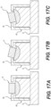
- the first flange 56 limits the pivoting movement of the base electrode 14 relative to the first hemispherical portion 30 of the base 12. More particularly, as generally shown in FIGS. 17A-17C , pivoting is limited to approximately 15 degrees in every direction according to the example embodiment, however, the first flange 56 could be sized to limit the pivoting to other angles.
- the retaining collar 48 prevents debris from entering the region of the first and second hemispherical portions 30, 36 in order to provide prolonged use of the welding assembly 10.
- an upper adapter 58 is coupled with the welding gun 16.
- the upper adapter 58 is made of a class 2 copper material, however, other highly conductive materials could be utilized.
- the upper adapter 58 extends axially between a proximal end 60 and a distal end 62, with a plurality of third threads 64 defined adjacent to the proximal end 60 for threadedly fixing the upper adapter 58 to the welding gun 16.
- the distal end 62 of the upper adapter 58 defines a third hemispherical portion 66 that concaves into the distal end 62.
- the upper adapter 58 further defines fourth threads 68 adjacent to the distal end 62.
- a plurality of second wire channels 70 extend generally axially through the upper adapter 58 and terminate at the distal end 62 for receiving wires for transmitting a current to the gun electrode 18.
- the second wire channels 70 are spaced apart and positioned so that at least one of the second wire channels 70 contacts the convex fourth hemispherical portion 72 of the gun electrode 18 with the gun electrode 18 being in any position throughout its range of motion.
- the gun electrode 18 is located against the upper adapter 58.
- the gun electrode 18 is made of a class 2 copper material, however, other highly conductive materials may be utilized.
- the gun electrode 18 has a convex fourth hemispherical portion 72 that nests with the third hemispherical portion 66 such that the convex fourth hemispherical portion 72 is rotatable 360 degrees and pivotable 360 degrees relative to the third hemispherical portion 66.
- the gun electrode 18 further includes a tubular segment 74 that extends axially from the fourth hemispherical portion 72 and terminates at a flat end for receiving and locating the second work piece 22 and the weld pin 42.
- an upper collar 76 that generally has a cylindrical shape is coupled with the upper adapter 58.
- the upper collar 76 is made of a non-magnetic stainless steel; however, other non-magnetic materials may be utilized.
- the upper collar 76 extends axially between a fixed end and 78 a guiding end 80.
- Fifth threads 82 are defined adjacent to the fixed end 78 for being threaded with the fourth threads 68 of the upper adapter 58.
- the upper collar 76 further includes a second flange 84 that extends radially inwardly from the guiding end 80 for limiting the pivoting movement of the gun electrode 18 relative to the upper adapter 58.
- pivoting is limited to approximately 15 degrees in every direction in the example embodiment, however, the second flange 84 could be sized to limit the pivoting to other angles.
- the upper collar 76 prevents debris from entering the region of the third and fourth hemispherical portions 66, 72 in order to provide prolonged use of the welding assembly 10.
- FIG. 2B shows the base and gun electrodes 14, 18 in a tilted left position while maintaining flat contact against the first and second work pieces 20, 22
- FIG. 2C shows the base and gun electrodes 14, 18 in a tilted right position while maintaining flat contact against the first and second work pieces 20, 22.
- the welding gun 16 starts in a raised position, and the base and gun electrodes 14, 18 are in their centered, un-pivoted state.
- the first work piece 20 (a plate in the example embodiment) is positioned on the base electrode 14 via either automatic or manual load.
- the base electrode 14 may be rotated and pivoted to compensate for any angular deflection caused by the first work piece 20 not being located along the original plane to ensure proper contact of the base electrode 14 against the first work piece 20.
- the base electrode 14 may be rotated and pivoted to match an angle of the first work piece 20.
- the second work piece 22 (which is a projection fastener in the case of the example embodiment), is placed over the weld pin 42.
- the gun electrode 18 is then lowered toward the base electrode 14 with the welding gun 16.
- the gun electrode 18 automatically rotates and pivots to match an angle of the base electrode 14 to provide full contact between the first and second work pieces 20, 22 (illustrated in FIG. 3D ).
- An electrical current is then supplied to the base and gun electrodes 14, 18, melting the second work piece 22 to the first work piece 20, to create a weld therebetween.
- one of the first and second work pieces 20, 22 may present one or more projections that engage the other work piece for concentrating the current and weld.
- hemispherical includes any surface extending along a portion of a sphere.
- the term “hemispherical” is not limited to exactly one-half of a sphere shape.
Landscapes
- Engineering & Computer Science (AREA)
- Mechanical Engineering (AREA)
- Robotics (AREA)
- Resistance Welding (AREA)
Description
- The subject disclosure generally relates to welding assemblies. More particularly, the subject disclosure relates to a spot welding assembly with at least one pivotable electrode for accommodating variances in work pieces, see
claims 1, 4, 8 and 11-12. - Spot welding assemblies are known in the art for welding first and second work pieces to one another. Spot welding assemblies typically include a base for supporting a base electrode and a welding gun for supporting a gun electrode. During a welding operation, the welding gun is moved toward the base in order to draw the first and second work pieces against one another. A current is then applied through the base and gun electrodes and the first and second work pieces in order to melt regions of at least one of the first work piece and/or the second work piece to form a weld therebetween. Further prior art are disclosed in
JP 2008 213032 A claims US 2 346 088 A andUS 2 523 367 A . - An issue with such spot welding assemblies, especially when the welding process is automated, is that the electrodes are static, and thus do not compensate for variations in work piece placement and/or dimensional variations among the work pieces, especially when the work pieces are not arranged parallel to a welding surface defined between the first and second electrodes. As such, the first and/or second work piece may not make adequately contact the electrodes, thus leading to an insufficient weld. In these situations, it is known to manually adjust an orientation of the welding gun and/or base to provide improved contact against the work pieces, however, such manual adjustments can be time consuming and labor intensive.
- According to the present invention, there are defined spot welding assemblies having the features of any of
claims - According to a first aspect of the present invention, a spot welding assembly for welding a first work piece to a second work piece is defined in
claim 1. - Because both of the base and the gun electrodes are pivotable, the electrodes are able to quickly be oriented flat against the work pieces even when the work pieces are not parallel to an original plane of the base and gun electrodes, such as when the work pieces are improperly located or irregularly dimensioned. Orienting the electrodes in this manner ensure sufficient electrical and thermal conductivity during welding in order to provide a sufficient weld. Such adjustments may be provided in both automated and manual welding operations.
- The subject spot welding assembly may be employed in projection welding applications, wherein at least one of the work pieces has at least one projection that engages the other work piece for focusing a current from the base and gun electrodes.
- Other advantages of the present invention will be readily appreciated, as the same becomes better understood by reference to the following detailed description when considered in connection with the accompanying drawings wherein:
-
FIG. 1 is a perspective view of an example spot welding assembly; -
FIGS. 2A-2B are front perspective views of work pieces located between base and gun electrodes of the example spot welding assembly, illustrating the base and gun electrodes being pivoted in different directions; -
FIGS. 3A-3D are front partial views of base and gun electrodes of the example spot welding assembly, illustrating the base and gun electrodes being pivoted in different directions; -
FIGS. 4A-4C are top, front and side views of a weld pin of the example spot welding assembly; -
FIGS. 5A-5C are top, front and side views of an upper collar of the example spot welding assembly; -
FIGS. 6A-6C are top, front and side views of a gun electrode of the example spot welding assembly; -
FIGS. 7A-7C are top, front and side views of an upper adapter of the example spot welding assembly; -
FIGS. 8A-8C are top, front and side views of a base electrodes of the example spot welding assembly; -
FIGS. 9A-9C are top, front and side views of a base of the example spot welding assembly; -
FIGS. 10A-10C are top, front and side views of a retaining collar of the example spot welding assembly; -
FIGS. 11A-11B are front partial views of the base and gun electrodes of the example spot welding assembly, illustrating first and second work pieces being located between the base and gun electrodes in an automatic operation; -
FIGS. 12A-12B are front partial views of the base and gun electrodes of the example spot welding assembly, illustrating first and second work pieces being located between the base and gun electrodes in a manual operation; -
FIGS. 13A-13C are front perspective views of the base and base electrode of the example spot welding assembly, illustrating the base electrode being pivoted into different positions; -
FIG. 14 is a front perspective view of the gun electrode of the example spot welding assembly in a centered position; -
FIG. 15 is a front perspective view of the example spot welding assembly, illustrating the base and gun electrodes securing first and second work pieces in pivoted positions; -
FIGS. 16A-16C are partial front schematic views of the gun electrode of the example spot welding assembly, illustrating the gun electrode being pivoted in various positions; -
FIGS. 17A-17C are partial front schematic views of the base electrode of the example spot welding assembly, illustrating the base electrode being pivoted in various positions; and -
FIG. 18 is a top perspective view of example first and second work pieces for being located and welded by the example spot welding assembly. - Referring to the Figures, wherein like numerals indicate correspond parts throughout the several views, a
spot welding assembly 10 is generally shown. With reference toFIG. 1 , thespot welding assembly 10 generally has abase 12 for supporting abase electrode 14, and awelding gun 16 for supporting agun electrode 18. As shown inFIGS. 12A-12B , afirst work piece 20 and asecond work piece 22 are positioned between the base andgun electrodes first work piece 20 is supported bytooling 23. With reference back toFIG. 1 , thewelding gun 16 is moveable toward and away from thebase 12 in order to make the first andsecond work pieces gun electrodes second work pieces second work pieces first work piece 20 is a flat plate and thesecond work piece 22 is a nut, but other types of work pieces may be utilized. As presented in the example embodiment, the subjectspot welding assembly 10 may specifically be a projection welding assembly, wherein at least one of thework pieces gun electrodes - As shown in
FIGS. 1 and9A-9C , thebase 12 has abottom portion 24 that is configured to be located on a die. Thebottom portion 24 may have various shapes, such as a cylindrical shape (e.g.,FIGS. 1-2C ) or a cuboid shaped (e.g.,FIGS. 9A-9C ). As best shown inFIGS. 9A-9C , the base 12 further has a generally cylindrical-shapedprojection portion 26 that extends upwardly from thebottom portion 24 along an axis A and terminates at a top surface 28. The top surface 28 defines a first hemispherical portion 30 that concaves axially downwardly. Theprojection portion 26 defines a plurality offirst threads 32 adjacent to thebottom portion 24. A plurality offirst wire channels 34 extend through theprojection portion 26 to the top surface 28 for receiving one or more wires for transmitting a current to thebase electrode 14. Thefirst wire channels 34 are spaced apart and positioned so that at least one of thefirst wire channels 34 contacts the convex secondhemispherical portion 36 of thebase electrode 14 with thebase electrode 14 being in any position throughout its range of motion. - As illustrated in
FIGS. 3A-3D and8A-8C , thebase electrode 14 is positioned against the first hemispherical portion 30 of thebase 12. According to the example embodiment, the base electrode is made of a class 2 copper material, but other highly conductive materials could be utilized. Thebase electrode 14 has a convex secondhemispherical portion 36 that nests with the first hemispherical portion 30 such that the secondhemispherical portion 36 is rotatable 360 degrees and pivotable 360 degrees relative to the first hemispherical portion 30. Thebase electrode 14 further has acylindrical projection 38 that extends upwardly from the secondhemispherical portion 36 to a flat surface for supporting thefirst work piece 20. Thebase electrode 14 further defines apassage 40 that extends axially therethrough. - As illustrated in
FIGS. 3A-3D andFIGS. 4A-4C , aweld pin 42 is received by thepassage 40 of thebase electrode 14. According to the example embodiment, theweld pin 42 is made of a non-magnetic stainless steel; however, other non-magnetic materials could be utilized. Theweld pin 42 extends axially from a bulgingend 44 to atip 46 that tapers to a point axially outside of thepassage 40. The bulgingend 44 of theweld pin 42 engages and is pivotable along the first hemispherical portion 30 with the secondhemispherical portion 36 of thebase electrode 14. Theweld pin 42 is configured to assist in aligning thesecond work piece 22 relative to thefirst work piece 20 by being received by thesecond work piece 22 and atubular segment 46 of the gun electrode 18 (discussed in further detail below). The pointedtip 46 of theweld pin 42 assists in guiding theweld pin 42 into thesecond work piece 22 andtubular segment 46. Alternatively or additionally, theweld pin 42 may be configured to contact thefirst work piece 20. For example, theweld pin 42 may be located into a channel of thefirst work piece 20 to assist in locating thefirst work piece 20. - As illustrated in
FIGS. 3A-3D andFIGS. 10A-10C , a retainingcollar 48 that generally has a tube shape receives theprojection portion 26 of thebase 12. According to the example embodiment, the retainingcollar 48 is made of a non-magnetic stainless steel material; however, other materials could be utilized. The retainingcollar 48 extends axially between abottom end 50 and atop end 52. A plurality ofsecond threads 54 are defined adjacent to thebottom end 50. Thesecond threads 54 are arranged to be threaded with thefirst threads 32 of thebase 12 for securing the retainingcollar 48 to thebase 12. Afirst flange 56 extends radially inwardly from thetop end 52. Thefirst flange 56 terminates radially adjacent to, and in axial alignment with theprojection 38 of thebase electrode 14. Thefirst flange 56 limits the pivoting movement of thebase electrode 14 relative to the first hemispherical portion 30 of thebase 12. More particularly, as generally shown inFIGS. 17A-17C , pivoting is limited to approximately 15 degrees in every direction according to the example embodiment, however, thefirst flange 56 could be sized to limit the pivoting to other angles. In addition to limiting pivoting movement of thebase electrode 14, the retainingcollar 48 prevents debris from entering the region of the first and secondhemispherical portions 30, 36 in order to provide prolonged use of thewelding assembly 10. - As best shown in
FIGS. 7A-7C , anupper adapter 58 is coupled with thewelding gun 16. According to the example embodiment, theupper adapter 58 is made of a class 2 copper material, however, other highly conductive materials could be utilized. Theupper adapter 58 extends axially between aproximal end 60 and a distal end 62, with a plurality ofthird threads 64 defined adjacent to theproximal end 60 for threadedly fixing theupper adapter 58 to thewelding gun 16. The distal end 62 of theupper adapter 58 defines a third hemispherical portion 66 that concaves into the distal end 62. Theupper adapter 58 further definesfourth threads 68 adjacent to the distal end 62. A plurality ofsecond wire channels 70 extend generally axially through theupper adapter 58 and terminate at the distal end 62 for receiving wires for transmitting a current to thegun electrode 18. Thesecond wire channels 70 are spaced apart and positioned so that at least one of thesecond wire channels 70 contacts the convex fourthhemispherical portion 72 of thegun electrode 18 with thegun electrode 18 being in any position throughout its range of motion. - As best shown in
FIGS. 3A-3D and6A-6C , thegun electrode 18 is located against theupper adapter 58. According to the example embodiment, thegun electrode 18 is made of a class 2 copper material, however, other highly conductive materials may be utilized. Thegun electrode 18 has a convex fourthhemispherical portion 72 that nests with the third hemispherical portion 66 such that the convex fourthhemispherical portion 72 is rotatable 360 degrees and pivotable 360 degrees relative to the third hemispherical portion 66. Thegun electrode 18 further includes atubular segment 74 that extends axially from the fourthhemispherical portion 72 and terminates at a flat end for receiving and locating thesecond work piece 22 and theweld pin 42. - As best shown in
FIGS. 3A-3D and5A-5C , anupper collar 76 that generally has a cylindrical shape is coupled with theupper adapter 58. According to the example embodiment, theupper collar 76 is made of a non-magnetic stainless steel; however, other non-magnetic materials may be utilized. Theupper collar 76 extends axially between a fixed end and 78 a guidingend 80.Fifth threads 82 are defined adjacent to thefixed end 78 for being threaded with thefourth threads 68 of theupper adapter 58. Theupper collar 76 further includes asecond flange 84 that extends radially inwardly from the guidingend 80 for limiting the pivoting movement of thegun electrode 18 relative to theupper adapter 58. More particularly, as generally shown inFIGS. 16A-16C , pivoting is limited to approximately 15 degrees in every direction in the example embodiment, however, thesecond flange 84 could be sized to limit the pivoting to other angles. In addition to limiting pivoting movement of thegun electrode 18, theupper collar 76 prevents debris from entering the region of the third and fourthhemispherical portions 66, 72 in order to provide prolonged use of thewelding assembly 10. - During use of the
spot welding assembly 10, the pivoting movement and rotation of the base andgun electrodes gun electrodes second work pieces second work pieces second work pieces gun electrodes FIG. 2A shows the base andgun electrodes first work piece 20 positioned generally along the original plane,FIG. 2B shows the base andgun electrodes second work pieces FIG. 2C shows the base andgun electrodes second work pieces - As illustrated in
FIG. 1 , during operation, thewelding gun 16 starts in a raised position, and the base andgun electrodes base electrode 14 via either automatic or manual load. At this point, thebase electrode 14 may be rotated and pivoted to compensate for any angular deflection caused by thefirst work piece 20 not being located along the original plane to ensure proper contact of thebase electrode 14 against thefirst work piece 20. Specifically, thebase electrode 14 may be rotated and pivoted to match an angle of thefirst work piece 20. Once thefirst work piece 20 is located, the second work piece 22 (which is a projection fastener in the case of the example embodiment), is placed over theweld pin 42. Thegun electrode 18 is then lowered toward thebase electrode 14 with thewelding gun 16. Upon contact of thesecond work piece 22 against thefirst work piece 20, thegun electrode 18 automatically rotates and pivots to match an angle of thebase electrode 14 to provide full contact between the first andsecond work pieces 20, 22 (illustrated inFIG. 3D ). An electrical current is then supplied to the base andgun electrodes second work piece 22 to thefirst work piece 20, to create a weld therebetween. It should be appreciated that one of the first andsecond work pieces - Unless otherwise defined, the term "hemispherical," as used in the present application, includes any surface extending along a portion of a sphere. The term "hemispherical" is not limited to exactly one-half of a sphere shape.
- The foregoing description is not intended to be exhaustive or to limit the disclosure. Individual elements or features of a particular embodiment are generally not limited to that particular embodiment, but, where applicable, are interchangeable and can be used in a selected embodiment, even if not specifically shown or described. The same may also be varied in many ways. Such variations are not to be regarded as a departure from the invention, and all such modifications are intended to be included within the scope of the invention as defined in the appended claims.
Claims (12)
- A spot welding assembly (10) comprising: a base (12); a base electrode (14) coupled with the base (12) for supporting a first work piece (20); a welding gun (16) moveable toward and away from the base (12); a gun electrode (18) coupled with the welding gun (16) for supporting a second work piece (22) and for locating the second work piece (22) against the first work piece (20) upon movement of the welding gun (16) toward the base (12) to allow the first and second work pieces (20, 22) to be welded to one another,the spot welding assembly (10) being characterised in that:the base electrode (14) is pivotable relative to the base (12) and the gun electrode (18) is pivotable relative to the welding gun (16).
- The spot welding assembly (10) of Claim 1, wherein the base electrode (14) is pivotable 360 degrees relative to the base (12) and the gun electrode (18) is pivotable 360-degrees relative to the welding gun (16).
- The spot welding assembly (10) of any of Claims 1 or 2, wherein both of the base (12) and the welding gun (16) each includes a concave hemispherical portion (30) configured to receive a convex hemispherical portion (36) of a corresponding one of the gun electrode (18) or the base electrode (14).
- A spot welding assembly (10) comprising: a base (12); a base electrode (14) coupled with the base (12) for supporting a first work piece (20); a welding gun (16) moveable toward and away from the base (12); a gun electrode (18) coupled with the welding gun (16) for supporting a second work piece (22) and for locating the second work piece (22) against the first work piece (20) upon movement of the welding gun (16) toward the base (12) to allow the first and second work pieces (20, 22) to be welded to one another;
the spot welding assembly (10) being characterised by:
at least one of:the base electrode (14) being pivotable relative to the base (12), or the gun electrode (18) being pivotable relative to the welding gun (16),and, in that:at least one of the base (12) or the welding gun (16) includes a collar (48) having a flange (56) extending radially inwardly for limiting a pivoting movement of a corresponding one of the electrodes (14, 18). - The spot welding assembly (10) of Claim 4, wherein each of the base (12) and the welding gun (16) includes a collar (48) having a flange (56) extending radially inwardly for limiting a pivoting movement of a corresponding one of the electrodes (14, 18).
- The spot welding assembly(10) of Claim 4, wherein the collar (48) includes threads for securing the collar onto an upper adapter (58) of the welding gun (16) or onto a cylindrical-shaped projection of the base (12).
- The spot welding assembly (10) of Claim 4, wherein the flange (56) is configured to limit the pivoting movement of the corresponding one of the electrodes (14, 18) to about 15 degrees.
- A spot welding assembly (10) comprising: a base (12); a base electrode (14) coupled with the base (12) for supporting a first work piece (20); a welding gun (16) moveable toward and away from the base (12); a gun electrode (18) coupled with the welding gun (16) for supporting a second work piece (22) and for locating the second work piece (22) against the first work piece (20) upon movement of the welding gun (16) toward the base (12) to allow the first and second work pieces (20, 22) to be welded to one another;
the spot welding assembly (10) being characterised by:
at least one of:the base electrode (14) being pivotable relative to the base (12), or the gun electrode (18) being pivotable relative to the welding gun (16),and, in that:
at least one of the electrodes (14, 18) defines a passage (40) extending axially therethrough for receiving a weld pin (42) therethrough, the weld pin (42) being configured to align the second work piece (22) with the first work piece (20). - The spot welding assembly (10) of Claim 8, wherein at least one of the base (12) or the welding gun (16) includes a concave hemispherical portion (30) configured to receive a convex hemispherical portion (36) of a corresponding one of the gun electrode (18) or the base electrode (14); and wherein the weld pin (42) extends axially from a bulging end (44) to a tip (46) that tapers to a point axially outside of the passage (40), the bulging end (44) of the weld pin (42) being configured to engage and be pivotable along the concave hemispherical portion (30) of the at least one of the base (12) or the welding gun (16).
- The spot welding assembly (10) of Claim 8, wherein another one of the electrodes (14, 18) from the at least one of the electrodes (14, 18) defining the passage (40) for receiving the weld pin (42) therethrough further includes a tubular segment (46) configured to receive the weld pin (42) upon movement of the welding gun (16) toward the base (12).
- A spot welding assembly (10) comprising: a base (12); a base electrode (14) coupled with the base (12) for supporting a first work piece (20); a welding gun (16) moveable toward and away from the base (12); a gun electrode (18) coupled with the welding gun (16) for supporting a second work piece (22) and for locating the second work piece (22) against the first work piece (20) upon movement of the welding gun (16) toward the base (12) to allow the first and second work pieces (20, 22) to be welded to one another;
the spot welding assembly (10) being characterised by:
the base electrode (14) being pivotable relative to the base (12), wherein the base electrode (14) is pivotable throughout a range of motion; wherein the base (12) includes a projection portion (26) defining a plurality of wire channels (34) extending therethrough for receiving wires for transmitting a current to the base electrode (14); and wherein the wire channels (34) are spaced apart and positioned so that at least one of the wire channels (34) contacts the base electrode (14) with the base electrode (14) being in any position throughout its range of motion. - A spot welding assembly (10) comprising: a base (12); a base electrode (14) coupled with the base (12) for supporting a first work piece (20); a welding gun (16) moveable toward and away from the base (12); a gun electrode (18) coupled with the welding gun (16) for supporting a second work piece (22) and for locating the second work piece (22) against the first work piece (20) upon movement of the welding gun (16) toward the base (12) to allow the first and second work pieces (20, 22) to be welded to one another;
the spot welding assembly (10) being characterised by:
the gun electrode (18) being pivotable relative to the welding gun (16), wherein the gun electrode (18) is pivotable throughout a range of motion; wherein the welding gun (16) includes an upper adapter (58) defining a plurality of wire channels (70) extending therethrough for receiving wires for transmitting a current to the gun electrode (18); and wherein the wire channels (70) are spaced apart and positioned so that at least one of the wire channels (70) contacts the gun electrode (18) with the gun electrode (18) being in any position throughout its range of motion.
Applications Claiming Priority (2)
| Application Number | Priority Date | Filing Date | Title |
|---|---|---|---|
| US201962910605P | 2019-10-04 | 2019-10-04 | |
| PCT/US2020/053228 WO2021067244A1 (en) | 2019-10-04 | 2020-09-29 | Spot welding assembly with pivotable electrodes |
Publications (3)
| Publication Number | Publication Date |
|---|---|
| EP4041486A1 EP4041486A1 (en) | 2022-08-17 |
| EP4041486A4 EP4041486A4 (en) | 2023-11-01 |
| EP4041486B1 true EP4041486B1 (en) | 2025-03-26 |
Family
ID=75337439
Family Applications (1)
| Application Number | Title | Priority Date | Filing Date |
|---|---|---|---|
| EP20872796.6A Active EP4041486B1 (en) | 2019-10-04 | 2020-09-29 | Spot welding assembly with pivotable electrodes |
Country Status (4)
| Country | Link |
|---|---|
| EP (1) | EP4041486B1 (en) |
| CN (1) | CN114502311A (en) |
| CA (1) | CA3153346A1 (en) |
| WO (1) | WO2021067244A1 (en) |
Family Cites Families (7)
| Publication number | Priority date | Publication date | Assignee | Title |
|---|---|---|---|---|
| US1996901A (en) * | 1933-06-12 | 1935-04-09 | Northrop Corp | Welding apparatus |
| US2346088A (en) * | 1943-02-05 | 1944-04-04 | Stackpole Carbon Co | Self-aligning electrode |
| US2523367A (en) * | 1949-06-15 | 1950-09-26 | Mallory & Co Inc P R | Swivel type spot welding electrode |
| DE1297960B (en) * | 1965-08-28 | 1969-06-19 | Claas Guenther | Electrode for electrical resistance spot welding devices |
| US7564005B2 (en) * | 2001-07-10 | 2009-07-21 | Doben Limited | Resistance welding fastener electrode and monitor and method of using same |
| US7112757B2 (en) * | 2004-08-24 | 2006-09-26 | General Motors Corporation | Programmable resistance seam welding apparatus and method |
| JP2008213032A (en) | 2007-03-02 | 2008-09-18 | Yoshitaka Aoyama | Device for controlling passage of projection bolt |
-
2020
- 2020-09-29 CN CN202080070092.4A patent/CN114502311A/en active Pending
- 2020-09-29 CA CA3153346A patent/CA3153346A1/en active Pending
- 2020-09-29 WO PCT/US2020/053228 patent/WO2021067244A1/en not_active Ceased
- 2020-09-29 EP EP20872796.6A patent/EP4041486B1/en active Active
Also Published As
| Publication number | Publication date |
|---|---|
| WO2021067244A1 (en) | 2021-04-08 |
| CN114502311A (en) | 2022-05-13 |
| EP4041486A1 (en) | 2022-08-17 |
| EP4041486A4 (en) | 2023-11-01 |
| CA3153346A1 (en) | 2021-04-08 |
Similar Documents
| Publication | Publication Date | Title |
|---|---|---|
| CN102744514B (en) | For the SERVO CONTROL rotating clamp of friction stir spot soldering equipment | |
| CN109789520B (en) | Clamping elements for clamping devices for welding workpieces, and clamping devices | |
| US8637788B2 (en) | Flexible conductor tube for a welding gun | |
| US9302341B2 (en) | Welding contact tip with conductive brush | |
| EP2457682A1 (en) | Welding torch, welding tip, and welding robot | |
| US10644413B2 (en) | Method for joining electrical conductors | |
| US20200306874A1 (en) | Friction stir welding tool | |
| CN102216020A (en) | Welding feed contact chip and welding torch using same | |
| US12569927B2 (en) | Spot welding assembly with pivotable electrodes | |
| EP3505288A1 (en) | Welding torch and welding device | |
| CA3153346A1 (en) | Spot welding assembly with pivotable electrodes | |
| US8847098B2 (en) | Planetary resistance welding device and methods therefor | |
| EP0273162A2 (en) | Two-piece cathode cup | |
| CA2654905A1 (en) | Flexible conductor tube for a welding gun | |
| EP4000784B1 (en) | Welding torch, welding device and method of multi-wire narrow-gap welding | |
| JPS61123479A (en) | Apparatus for spot welding of metal thin plate part | |
| CN119260287A (en) | A sleeve fixing fixture and a manufacturing method thereof | |
| KR101489060B1 (en) | Tandem welding torch | |
| KR100722131B1 (en) | Electrode Arrangement of Spot Welder | |
| JP2002369436A (en) | Motor stator and method of assembling motor stator | |
| JP5277701B2 (en) | Welding equipment | |
| EP4079439A2 (en) | Spot welding assembly with pivotable electrodes | |
| EP3183088B1 (en) | Rotatable plasma cutting torch assembly with short connections | |
| JP4197263B2 (en) | Electrode device for projection welding | |
| JPH06142930A (en) | Welding wire feeder |
Legal Events
| Date | Code | Title | Description |
|---|---|---|---|
| STAA | Information on the status of an ep patent application or granted ep patent |
Free format text: STATUS: THE INTERNATIONAL PUBLICATION HAS BEEN MADE |
|
| PUAI | Public reference made under article 153(3) epc to a published international application that has entered the european phase |
Free format text: ORIGINAL CODE: 0009012 |
|
| STAA | Information on the status of an ep patent application or granted ep patent |
Free format text: STATUS: REQUEST FOR EXAMINATION WAS MADE |
|
| 17P | Request for examination filed |
Effective date: 20220502 |
|
| AK | Designated contracting states |
Kind code of ref document: A1 Designated state(s): AL AT BE BG CH CY CZ DE DK EE ES FI FR GB GR HR HU IE IS IT LI LT LU LV MC MK MT NL NO PL PT RO RS SE SI SK SM TR |
|
| DAV | Request for validation of the european patent (deleted) | ||
| DAX | Request for extension of the european patent (deleted) | ||
| A4 | Supplementary search report drawn up and despatched |
Effective date: 20230928 |
|
| RIC1 | Information provided on ipc code assigned before grant |
Ipc: B23K 11/31 20060101ALI20230922BHEP Ipc: B23K 11/00 20060101ALI20230922BHEP Ipc: B23K 11/30 20060101AFI20230922BHEP |
|
| RIC1 | Information provided on ipc code assigned before grant |
Ipc: B23K 11/31 20060101ALI20240806BHEP Ipc: B23K 11/00 20060101ALI20240806BHEP Ipc: B23K 11/30 20060101AFI20240806BHEP |
|
| GRAP | Despatch of communication of intention to grant a patent |
Free format text: ORIGINAL CODE: EPIDOSNIGR1 |
|
| STAA | Information on the status of an ep patent application or granted ep patent |
Free format text: STATUS: GRANT OF PATENT IS INTENDED |
|
| INTG | Intention to grant announced |
Effective date: 20241024 |
|
| GRAS | Grant fee paid |
Free format text: ORIGINAL CODE: EPIDOSNIGR3 |
|
| GRAA | (expected) grant |
Free format text: ORIGINAL CODE: 0009210 |
|
| STAA | Information on the status of an ep patent application or granted ep patent |
Free format text: STATUS: THE PATENT HAS BEEN GRANTED |
|
| P01 | Opt-out of the competence of the unified patent court (upc) registered |
Free format text: CASE NUMBER: APP_6232/2025 Effective date: 20250206 |
|
| AK | Designated contracting states |
Kind code of ref document: B1 Designated state(s): AL AT BE BG CH CY CZ DE DK EE ES FI FR GB GR HR HU IE IS IT LI LT LU LV MC MK MT NL NO PL PT RO RS SE SI SK SM TR |
|
| REG | Reference to a national code |
Ref country code: GB Ref legal event code: FG4D |
|
| REG | Reference to a national code |
Ref country code: CH Ref legal event code: EP |
|
| REG | Reference to a national code |
Ref country code: DE Ref legal event code: R096 Ref document number: 602020048495 Country of ref document: DE |
|
| REG | Reference to a national code |
Ref country code: IE Ref legal event code: FG4D |
|
| PG25 | Lapsed in a contracting state [announced via postgrant information from national office to epo] |
Ref country code: RS Free format text: LAPSE BECAUSE OF FAILURE TO SUBMIT A TRANSLATION OF THE DESCRIPTION OR TO PAY THE FEE WITHIN THE PRESCRIBED TIME-LIMIT Effective date: 20250626 |
|
| PG25 | Lapsed in a contracting state [announced via postgrant information from national office to epo] |
Ref country code: FI Free format text: LAPSE BECAUSE OF FAILURE TO SUBMIT A TRANSLATION OF THE DESCRIPTION OR TO PAY THE FEE WITHIN THE PRESCRIBED TIME-LIMIT Effective date: 20250326 |
|
| REG | Reference to a national code |
Ref country code: LT Ref legal event code: MG9D |
|
| PG25 | Lapsed in a contracting state [announced via postgrant information from national office to epo] |
Ref country code: NO Free format text: LAPSE BECAUSE OF FAILURE TO SUBMIT A TRANSLATION OF THE DESCRIPTION OR TO PAY THE FEE WITHIN THE PRESCRIBED TIME-LIMIT Effective date: 20250626 |
|
| PG25 | Lapsed in a contracting state [announced via postgrant information from national office to epo] |
Ref country code: HR Free format text: LAPSE BECAUSE OF FAILURE TO SUBMIT A TRANSLATION OF THE DESCRIPTION OR TO PAY THE FEE WITHIN THE PRESCRIBED TIME-LIMIT Effective date: 20250326 |
|
| PG25 | Lapsed in a contracting state [announced via postgrant information from national office to epo] |
Ref country code: LV Free format text: LAPSE BECAUSE OF FAILURE TO SUBMIT A TRANSLATION OF THE DESCRIPTION OR TO PAY THE FEE WITHIN THE PRESCRIBED TIME-LIMIT Effective date: 20250326 |
|
| PG25 | Lapsed in a contracting state [announced via postgrant information from national office to epo] |
Ref country code: GR Free format text: LAPSE BECAUSE OF FAILURE TO SUBMIT A TRANSLATION OF THE DESCRIPTION OR TO PAY THE FEE WITHIN THE PRESCRIBED TIME-LIMIT Effective date: 20250627 Ref country code: BG Free format text: LAPSE BECAUSE OF FAILURE TO SUBMIT A TRANSLATION OF THE DESCRIPTION OR TO PAY THE FEE WITHIN THE PRESCRIBED TIME-LIMIT Effective date: 20250326 |
|
| REG | Reference to a national code |
Ref country code: NL Ref legal event code: MP Effective date: 20250326 |
|
| PG25 | Lapsed in a contracting state [announced via postgrant information from national office to epo] |
Ref country code: NL Free format text: LAPSE BECAUSE OF FAILURE TO SUBMIT A TRANSLATION OF THE DESCRIPTION OR TO PAY THE FEE WITHIN THE PRESCRIBED TIME-LIMIT Effective date: 20250326 |
|
| PG25 | Lapsed in a contracting state [announced via postgrant information from national office to epo] |
Ref country code: SE Free format text: LAPSE BECAUSE OF FAILURE TO SUBMIT A TRANSLATION OF THE DESCRIPTION OR TO PAY THE FEE WITHIN THE PRESCRIBED TIME-LIMIT Effective date: 20250326 |
|
| REG | Reference to a national code |
Ref country code: AT Ref legal event code: MK05 Ref document number: 1778585 Country of ref document: AT Kind code of ref document: T Effective date: 20250326 |
|
| PG25 | Lapsed in a contracting state [announced via postgrant information from national office to epo] |
Ref country code: SM Free format text: LAPSE BECAUSE OF FAILURE TO SUBMIT A TRANSLATION OF THE DESCRIPTION OR TO PAY THE FEE WITHIN THE PRESCRIBED TIME-LIMIT Effective date: 20250326 |
|
| PG25 | Lapsed in a contracting state [announced via postgrant information from national office to epo] |
Ref country code: ES Free format text: LAPSE BECAUSE OF FAILURE TO SUBMIT A TRANSLATION OF THE DESCRIPTION OR TO PAY THE FEE WITHIN THE PRESCRIBED TIME-LIMIT Effective date: 20250326 Ref country code: PT Free format text: LAPSE BECAUSE OF FAILURE TO SUBMIT A TRANSLATION OF THE DESCRIPTION OR TO PAY THE FEE WITHIN THE PRESCRIBED TIME-LIMIT Effective date: 20250728 |
|
| PGFP | Annual fee paid to national office [announced via postgrant information from national office to epo] |
Ref country code: DE Payment date: 20250805 Year of fee payment: 6 |
|
| PG25 | Lapsed in a contracting state [announced via postgrant information from national office to epo] |
Ref country code: IT Free format text: LAPSE BECAUSE OF FAILURE TO SUBMIT A TRANSLATION OF THE DESCRIPTION OR TO PAY THE FEE WITHIN THE PRESCRIBED TIME-LIMIT Effective date: 20250326 Ref country code: PL Free format text: LAPSE BECAUSE OF FAILURE TO SUBMIT A TRANSLATION OF THE DESCRIPTION OR TO PAY THE FEE WITHIN THE PRESCRIBED TIME-LIMIT Effective date: 20250326 |
|
| PG25 | Lapsed in a contracting state [announced via postgrant information from national office to epo] |
Ref country code: AT Free format text: LAPSE BECAUSE OF FAILURE TO SUBMIT A TRANSLATION OF THE DESCRIPTION OR TO PAY THE FEE WITHIN THE PRESCRIBED TIME-LIMIT Effective date: 20250326 |
|
| PG25 | Lapsed in a contracting state [announced via postgrant information from national office to epo] |
Ref country code: EE Free format text: LAPSE BECAUSE OF FAILURE TO SUBMIT A TRANSLATION OF THE DESCRIPTION OR TO PAY THE FEE WITHIN THE PRESCRIBED TIME-LIMIT Effective date: 20250326 |
|
| PG25 | Lapsed in a contracting state [announced via postgrant information from national office to epo] |
Ref country code: RO Free format text: LAPSE BECAUSE OF FAILURE TO SUBMIT A TRANSLATION OF THE DESCRIPTION OR TO PAY THE FEE WITHIN THE PRESCRIBED TIME-LIMIT Effective date: 20250326 |
|
| PG25 | Lapsed in a contracting state [announced via postgrant information from national office to epo] |
Ref country code: SK Free format text: LAPSE BECAUSE OF FAILURE TO SUBMIT A TRANSLATION OF THE DESCRIPTION OR TO PAY THE FEE WITHIN THE PRESCRIBED TIME-LIMIT Effective date: 20250326 |
|
| PG25 | Lapsed in a contracting state [announced via postgrant information from national office to epo] |
Ref country code: IS Free format text: LAPSE BECAUSE OF FAILURE TO SUBMIT A TRANSLATION OF THE DESCRIPTION OR TO PAY THE FEE WITHIN THE PRESCRIBED TIME-LIMIT Effective date: 20250726 |
|
| REG | Reference to a national code |
Ref country code: DE Ref legal event code: R097 Ref document number: 602020048495 Country of ref document: DE |
|
| PG25 | Lapsed in a contracting state [announced via postgrant information from national office to epo] |
Ref country code: DK Free format text: LAPSE BECAUSE OF FAILURE TO SUBMIT A TRANSLATION OF THE DESCRIPTION OR TO PAY THE FEE WITHIN THE PRESCRIBED TIME-LIMIT Effective date: 20250326 |
|
| PG25 | Lapsed in a contracting state [announced via postgrant information from national office to epo] |
Ref country code: CZ Free format text: LAPSE BECAUSE OF FAILURE TO SUBMIT A TRANSLATION OF THE DESCRIPTION OR TO PAY THE FEE WITHIN THE PRESCRIBED TIME-LIMIT Effective date: 20250326 |
|
| PLBE | No opposition filed within time limit |
Free format text: ORIGINAL CODE: 0009261 |
|
| STAA | Information on the status of an ep patent application or granted ep patent |
Free format text: STATUS: NO OPPOSITION FILED WITHIN TIME LIMIT |
|
| REG | Reference to a national code |
Ref country code: CH Ref legal event code: L10 Free format text: ST27 STATUS EVENT CODE: U-0-0-L10-L00 (AS PROVIDED BY THE NATIONAL OFFICE) Effective date: 20260211 |
|
| 26N | No opposition filed |
Effective date: 20260105 |
|
| REG | Reference to a national code |
Ref country code: CH Ref legal event code: H13 Free format text: ST27 STATUS EVENT CODE: U-0-0-H10-H13 (AS PROVIDED BY THE NATIONAL OFFICE) Effective date: 20260425 |
|
| PG25 | Lapsed in a contracting state [announced via postgrant information from national office to epo] |
Ref country code: LU Free format text: LAPSE BECAUSE OF NON-PAYMENT OF DUE FEES Effective date: 20250929 |
|
| GBPC | Gb: european patent ceased through non-payment of renewal fee |
Effective date: 20250929 |
|
| REG | Reference to a national code |
Ref country code: BE Ref legal event code: MM Effective date: 20250930 |
|
| PG25 | Lapsed in a contracting state [announced via postgrant information from national office to epo] |
Ref country code: LT Free format text: LAPSE BECAUSE OF FAILURE TO SUBMIT A TRANSLATION OF THE DESCRIPTION OR TO PAY THE FEE WITHIN THE PRESCRIBED TIME-LIMIT Effective date: 20250326 |
|
| PG25 | Lapsed in a contracting state [announced via postgrant information from national office to epo] |
Ref country code: MC Free format text: LAPSE BECAUSE OF FAILURE TO SUBMIT A TRANSLATION OF THE DESCRIPTION OR TO PAY THE FEE WITHIN THE PRESCRIBED TIME-LIMIT Effective date: 20250326 |
|
| PG25 | Lapsed in a contracting state [announced via postgrant information from national office to epo] |
Ref country code: GB Free format text: LAPSE BECAUSE OF NON-PAYMENT OF DUE FEES Effective date: 20250929 |
|
| PG25 | Lapsed in a contracting state [announced via postgrant information from national office to epo] |
Ref country code: CH Free format text: LAPSE BECAUSE OF NON-PAYMENT OF DUE FEES Effective date: 20250930 Ref country code: BE Free format text: LAPSE BECAUSE OF NON-PAYMENT OF DUE FEES Effective date: 20250930 Ref country code: IE Free format text: LAPSE BECAUSE OF NON-PAYMENT OF DUE FEES Effective date: 20250929 |
|
| PG25 | Lapsed in a contracting state [announced via postgrant information from national office to epo] |
Ref country code: FR Free format text: LAPSE BECAUSE OF NON-PAYMENT OF DUE FEES Effective date: 20250930 |