EP4040758A1 - Network including data integrity monitoring - Google Patents
Network including data integrity monitoring Download PDFInfo
- Publication number
- EP4040758A1 EP4040758A1 EP22155441.3A EP22155441A EP4040758A1 EP 4040758 A1 EP4040758 A1 EP 4040758A1 EP 22155441 A EP22155441 A EP 22155441A EP 4040758 A1 EP4040758 A1 EP 4040758A1
- Authority
- EP
- European Patent Office
- Prior art keywords
- network
- error data
- link
- data
- message
- Prior art date
- Legal status (The legal status is an assumption and is not a legal conclusion. Google has not performed a legal analysis and makes no representation as to the accuracy of the status listed.)
- Pending
Links
Images




Classifications
-
- H—ELECTRICITY
- H04—ELECTRIC COMMUNICATION TECHNIQUE
- H04L—TRANSMISSION OF DIGITAL INFORMATION, e.g. TELEGRAPHIC COMMUNICATION
- H04L43/00—Arrangements for monitoring or testing data switching networks
- H04L43/08—Monitoring or testing based on specific metrics, e.g. QoS, energy consumption or environmental parameters
- H04L43/0823—Errors, e.g. transmission errors
- H04L43/0847—Transmission error
-
- H—ELECTRICITY
- H04—ELECTRIC COMMUNICATION TECHNIQUE
- H04L—TRANSMISSION OF DIGITAL INFORMATION, e.g. TELEGRAPHIC COMMUNICATION
- H04L63/00—Network architectures or network communication protocols for network security
- H04L63/12—Applying verification of the received information
- H04L63/123—Applying verification of the received information received data contents, e.g. message integrity
-
- H—ELECTRICITY
- H04—ELECTRIC COMMUNICATION TECHNIQUE
- H04L—TRANSMISSION OF DIGITAL INFORMATION, e.g. TELEGRAPHIC COMMUNICATION
- H04L41/00—Arrangements for maintenance, administration or management of data switching networks, e.g. of packet switching networks
- H04L41/06—Management of faults, events, alarms or notifications
- H04L41/0654—Management of faults, events, alarms or notifications using network fault recovery
- H04L41/0659—Management of faults, events, alarms or notifications using network fault recovery by isolating or reconfiguring faulty entities
-
- H—ELECTRICITY
- H04—ELECTRIC COMMUNICATION TECHNIQUE
- H04L—TRANSMISSION OF DIGITAL INFORMATION, e.g. TELEGRAPHIC COMMUNICATION
- H04L41/00—Arrangements for maintenance, administration or management of data switching networks, e.g. of packet switching networks
- H04L41/06—Management of faults, events, alarms or notifications
- H04L41/0677—Localisation of faults
-
- H—ELECTRICITY
- H04—ELECTRIC COMMUNICATION TECHNIQUE
- H04L—TRANSMISSION OF DIGITAL INFORMATION, e.g. TELEGRAPHIC COMMUNICATION
- H04L41/00—Arrangements for maintenance, administration or management of data switching networks, e.g. of packet switching networks
- H04L41/06—Management of faults, events, alarms or notifications
- H04L41/0681—Configuration of triggering conditions
-
- H—ELECTRICITY
- H04—ELECTRIC COMMUNICATION TECHNIQUE
- H04L—TRANSMISSION OF DIGITAL INFORMATION, e.g. TELEGRAPHIC COMMUNICATION
- H04L43/00—Arrangements for monitoring or testing data switching networks
- H04L43/04—Processing captured monitoring data, e.g. for logfile generation
-
- H—ELECTRICITY
- H04—ELECTRIC COMMUNICATION TECHNIQUE
- H04L—TRANSMISSION OF DIGITAL INFORMATION, e.g. TELEGRAPHIC COMMUNICATION
- H04L43/00—Arrangements for monitoring or testing data switching networks
- H04L43/06—Generation of reports
- H04L43/065—Generation of reports related to network devices
-
- H—ELECTRICITY
- H04—ELECTRIC COMMUNICATION TECHNIQUE
- H04L—TRANSMISSION OF DIGITAL INFORMATION, e.g. TELEGRAPHIC COMMUNICATION
- H04L43/00—Arrangements for monitoring or testing data switching networks
- H04L43/08—Monitoring or testing based on specific metrics, e.g. QoS, energy consumption or environmental parameters
- H04L43/0805—Monitoring or testing based on specific metrics, e.g. QoS, energy consumption or environmental parameters by checking availability
- H04L43/0817—Monitoring or testing based on specific metrics, e.g. QoS, energy consumption or environmental parameters by checking availability by checking functioning
-
- H—ELECTRICITY
- H04—ELECTRIC COMMUNICATION TECHNIQUE
- H04L—TRANSMISSION OF DIGITAL INFORMATION, e.g. TELEGRAPHIC COMMUNICATION
- H04L43/00—Arrangements for monitoring or testing data switching networks
- H04L43/16—Threshold monitoring
-
- H—ELECTRICITY
- H04—ELECTRIC COMMUNICATION TECHNIQUE
- H04L—TRANSMISSION OF DIGITAL INFORMATION, e.g. TELEGRAPHIC COMMUNICATION
- H04L43/00—Arrangements for monitoring or testing data switching networks
- H04L43/50—Testing arrangements
-
- H—ELECTRICITY
- H04—ELECTRIC COMMUNICATION TECHNIQUE
- H04L—TRANSMISSION OF DIGITAL INFORMATION, e.g. TELEGRAPHIC COMMUNICATION
- H04L45/00—Routing or path finding of packets in data switching networks
- H04L45/28—Routing or path finding of packets in data switching networks using route fault recovery
-
- H—ELECTRICITY
- H04—ELECTRIC COMMUNICATION TECHNIQUE
- H04L—TRANSMISSION OF DIGITAL INFORMATION, e.g. TELEGRAPHIC COMMUNICATION
- H04L45/00—Routing or path finding of packets in data switching networks
- H04L45/74—Address processing for routing
- H04L45/745—Address table lookup; Address filtering
Definitions
- the present disclosure relates to data communications and networks and more particularly to a network including data integrity monitoring.
- Networks for communicating data such as a data network onboard an airplane or other system, specify a probability of undetected erroneous data that is allowable for continued operation of the airplane or system.
- Possible types of corruption on data networks include message impersonation, ordinal integrity violation, excessive or increased latency, and data corruption.
- There is some probability of corruption from a line replaceable unit (LRU) or physical layer causes, such as electromagnetic emissions, vibration, dirty fiber optics, etc.
- LRU line replaceable unit
- Data integrity monitoring on a network, particularly a data network onboard an airplane is important for corrective action to be taken and to avoid or minimize grounding of the airplane.
- a method for monitoring data integrity on a network includes reading error data from an interface associated with a particular link of the network in response to error data being present in a message received on the particular link. The method also includes creating a report message including the error data and transmitting the report message to a network monitoring algorithm operable on a processor circuit. The network monitoring algorithm is configured to determine a data integrity of the particular link based on the error data.
- a method for monitoring data integrity on a network includes receiving a message over a link of the network by a network switch or a network node. The method also includes determining if the message includes error data and creating a report message in response to the message including error data. The method additionally includes transmitting the report message to a network data integrity manager to determine whether the link has a fault.
- a network including data integrity monitoring comprises a plurality of network switches.
- the plurality of network switches are configurable to selectively interconnect two or more network nodes from a plurality of network nodes.
- Each network switch includes a network switch processor circuit and a switching function operable on the network switch processor circuit. The switching function is configured to selectively connect the network switch to another network switch or a network node from the plurality of network nodes.
- Each network switch also includes a network switch error data reporting function operable on the network switch processor circuit and configured to: read error data from a switch interface associated with a particular link of the network; create a network switch report message including the error data; and transmit the network switch report message to a network monitoring algorithm.
- the network monitoring algorithm is configured to determine a data integrity of the particular link.
- the method and network further include determining the data integrity of the particular link by determining if the error data is greater than an error data threshold for the particular link.
- the data integrity of the particular link is faulty in response to the error data being greater than the error data threshold.
- the method and network further include performing a predetermined action in response to the particular link being faulty.
- the predetermined action includes at least one of: shutting down the particular link; or transmitting data using another link of the network until the particular link is repaired.
- reading the error data includes reading the error data from a network interface of a network node by an error data reporting function operable on a processor circuit of the network node, and wherein said transmitting the report message includes transmitting the report message by the error data reporting function of the network node.
- reading the error data includes reading the error data from a switch interface of a network switch by an error data reporting function operable on a processor circuit of the network switch, and wherein said transmitting the report message includes transmitting the report message by the error data reporting function of the network switch.
- the method and network further include receiving a particular report message, by a network monitoring node, for each link, from a plurality of links of the network, having error data on the link.
- the network monitoring node includes the network monitoring algorithm.
- the method and network further include reading the error data from the particular report message for each link and determining a data integrity of each link by determining if the error data is greater than an error data threshold for each link. The data integrity for the link is faulty in response to the error data being greater than the error data threshold.
- the method and network further include performing a predetermined action in response to the link being faulty.
- the method and network further include receiving the message over the particular link, wherein the message is received by one of a network switch or a network node.
- the method and network further include determining if the message includes the error data by using an embedded error detection method.
- the method and network further include increasing a count of an error data counter associated with the particular link by one (1) in a memory of the network switch or the network node in response to the error data being present based on the embedded error detection method.
- the report message is created after a preset time interval expires and the report message includes the count from the error data counter.
- the method and network further include transmitting the report message by an error data reporting function of the network switch or the network node that received the message, to a network data integrity manager.
- the network data integrity manager is configured to determine a probability of undetected corrupt messages being transmitted by the particular link using the count from the error data counter.
- the method and network further include using an embedded error detection method to determine if the message comprises error data.
- the method and network further include increasing a count of an error data counter associated with the link in response to the message including error data.
- the method and network further include allowing one or more additional messages to be received over the link in response to a preset time interval not having expired; and increasing the count of the error data counter for each additional message that includes error data.
- the report message includes the count of the error data counter.
- the method and network further include adding the count of the error data counter to a count of a corrupted data counter; comparing the count of the corrupted data counter to an error data threshold for the link; and determining that the link has a fault in response to the count of the corrupted data counter being greater than the error data threshold for the link.
- the method and network further including determining a probability of undetected corrupt messages being transmitted by the link using the count of the corrupted data counter; and transmitting a message that a probability of undetected corruption on the link has exceeded a design value in response to the count of the corrupted data counter being greater than the error data threshold for the link.
- At least some network nodes from the plurality of network nodes include a network node processor circuit; and a vehicle function operable on the network node processor circuit and configured to perform a particular function associated with a vehicle.
- At least some network nodes from the plurality of network nodes further include a network node error data reporting function operable on the network node processor circuit and configured to: read error data from a network interface associated with another particular link of the network; create a network node report message including the error data; and transmit the network node report message to the network monitoring algorithm, wherein the network monitoring algorithm is configured to determine a data integrity of the other particular link.
- the method and network further include a network monitoring node of the plurality of network nodes.
- the network monitoring node includes a processor circuit; the network monitoring algorithm operable on the processor circuit; a memory associated with the processor circuit; and a configuration table stored in the memory.
- the configuration table includes an identification of each link from a plurality of links of the network and an error data threshold associated with each link.
- the configuration table is configured to be used by the network monitoring algorithm to determine if the error data read from an interface associated with a certain link of the network is greater than the error data threshold for the certain link.
- the network monitoring node is configured to perform a set of functions including: receiving a particular report message for each link from a plurality of links of the network having error data on the link; reading the error data from the particular report message for each link; determining a data integrity of each link by determining if the error data is greater than an error data threshold for each link, wherein the data integrity for the link is faulty in response to the error data being greater than the error data threshold; and performing a predetermined action in response to the link being faulty.
- the network further includes a network data integrity manager.
- the network data integrity manager includes a processor circuit and a memory associated with the processor circuit.
- the memory includes computer-readable program instructions that, when executed by the processor circuit, cause the processor circuit to perform a set of functions including receiving a report error message comprising a count from an error data counter associated with a certain link. The count of the error data counter is increased in response to each message received over the particular link that includes error data.
- the set of functions also include adding the count of the error data counter to a count of a corrupted data counter.
- the set of functions further include comparing the count of the corrupted data counter to an error data threshold for the particular link and determining that the particular link has a fault in response to the count of the corrupted data counter being greater than the error data threshold for the particular link.
- a network device comprised in a network switch of a plurality of network switched (106) or in a network node of a plurality of network nodes (108), wherein the plurality of network switches (106) are configurable to selectively interconnect two or more network nodes (108) from the plurality of network nodes (108), comprises a processor and a memory associated with the processor, wherein the processor is configured to implement a method (700) for monitoring data integrity on a network (100, 200), the method comprising: receiving (704) a message (400) over a link (110) of the network (100, 200) by a network switch (106) or a network node (108); determining (706) if the message (400) comprises error data (128); creating (714) a report message (716) in response to the message (400) comprising error data (128); and transmitting (718) the report message (716) to a network data integrity manager (112) to determine whether the link (110) has a fault.
- the method further comprises: using (706) an embedded error detection method to determine if the message (400) comprises error data (128).
- the present disclosure may be a system, a method, and/or a computer program product.
- the computer program product may include a computer-readable storage medium (or media) having computer-readable program instructions thereon for causing a processor to carry out aspects of the present disclosure.
- the computer-readable storage medium can be a tangible device that can retain and store instructions for use by an instruction execution device.
- the computer-readable storage medium may be, for example, but is not limited to, an electronic storage device, a magnetic storage device, an optical storage device, an electromagnetic storage device, a semiconductor storage device, or any suitable combination of the foregoing.
- a non-exhaustive list of more specific examples of the computer-readable storage medium includes the following: a portable computer diskette, a hard disk, a random access memory (RAM), a read-only memory (ROM), an erasable programmable read-only memory (EPROM or Flash memory), a static random access memory (SRAM), a portable compact disc read-only memory (CD-ROM), a digital versatile disk (DVD), a memory stick, a floppy disk, a mechanically encoded device such as punch-cards or raised structures in a groove having instructions recorded thereon, and any suitable combination of the foregoing.
- RAM random access memory
- ROM read-only memory
- EPROM or Flash memory erasable programmable read-only memory
- SRAM static random access memory
- CD-ROM compact disc read-only memory
- DVD digital versatile disk
- memory stick a floppy disk
- a mechanically encoded device such as punch-cards or raised structures in a groove having instructions recorded thereon
- a computer-readable storage medium is not to be construed as being transitory signals per se, such as radio waves or other freely propagating electromagnetic waves, electromagnetic waves propagating through a waveguide or other transmission media (e.g., light pulses passing through a fiber-optic cable), or electrical signals transmitted through a wire.
- Computer-readable program instructions described herein can be downloaded to respective computing/processing devices from a computer-readable storage medium or to an external computer or external storage device via a network, for example, the Internet, a local area network, a wide area network and/or a wireless network.
- the network may comprise copper transmission cables, optical transmission fibers, wireless transmission, routers, firewalls, switches, gateway computers and/or edge servers.
- a network adapter card or network interface in each computing/processing device receives computer-readable program instructions from the network and forwards the computer-readable program instructions for storage in a computer-readable storage medium within the respective computing/processing device.
- Computer-readable program instructions for carrying out operations of the present disclosure may be assembler instructions, instruction-set-architecture (ISA) instructions, machine instructions, machine dependent instructions, microcode, firmware instructions, state-setting data, or either source code or object code written in any combination of one or more programming languages, including an object oriented programming language such as Smalltalk, C++ or the like, and conventional procedural programming languages, such as the "C" programming language or similar programming languages.
- the computer-readable program instructions may execute entirely on the user's computer, partly on the user's computer, as a stand-alone software package, partly on the user's computer and partly on a remote computer or entirely on the remote computer or server.
- the remote computer may be connected to the user's computer through any type of network, including a local area network (LAN) or a wide area network (WAN), or the connection may be made to an external computer (for example, through the Internet using an Internet Service Provider).
- electronic circuitry including, for example, programmable logic circuitry, field-programmable gate arrays (FPGA), or programmable logic arrays (PLA) may execute the computer-readable program instructions by utilizing state information of the computer-readable program instructions to personalize the electronic circuitry, in order to perform aspects of the present disclosure.
- These computer-readable program instructions may be provided to a processor of a general purpose computer, special purpose computer, or other programmable data processing apparatus to produce a machine, such that the instructions, which execute via the processor of the computer or other programmable data processing apparatus, create means for implementing the functions/acts specified in the flowchart and/or block diagram block or blocks.
- These computer-readable program instructions may also be stored in a computer-readable storage medium that can direct a computer, a programmable data processing apparatus, and/or other devices to function in a particular manner, such that the computer-readable storage medium having instructions stored therein comprises an article of manufacture including instructions which implement aspects of the function/act specified in the flowchart and/or block diagram block or blocks.
- the computer-readable program instructions may also be loaded onto a computer, other programmable data processing apparatus, or other device to cause a series of operational steps to be performed on the computer, other programmable apparatus or other device to produce a computer implemented process, such that the instructions which execute on the computer, other programmable apparatus, or other device implement the functions/acts specified in the flowchart and/or block diagram block or blocks.
- FIG. 1A is a block schematic diagram of an example of a network 100 including data integrity monitoring in accordance with an example of the present disclosure.
- the network 100 is a data network onboard a vehicle 104, such as an airplane or other vehicle or system.
- the network 100 includes a plurality of network switches 106 labeled as 106a-106n in FIG. 1A .
- the plurality of network switches 106a-106n are configurable to selectively interconnect two or more network nodes 108, labeled as 108a-108n in FIG. 1A by links 110.
- at least some of the network switches 106 and network nodes 108 are configured for data integrity monitoring or include features for data integrity monitoring.
- a network data integrity manager 112 is configured to monitor data integrity.
- An example of a method for monitoring data integrity on a network that is performable by the network data integrity manager 112 will be described in more detail with reference to FIGS. 7A and 7B .
- the network data integrity manager 112 is embodied in a general processing module 114.
- the general processing module 114 is also a network node 108a.
- the network data integrity manager 112 is configured to monitor data integrity on the network 100, as described in more detail herein, and perform a predetermined action or actions in response to detecting error data on a link 110 associated with a particular network switch 106 or network node 108. Examples of the predetermined action include, but are not necessarily limited to, shutting down the particular link 110, transmitting messages or data via an alternate link 110, and/or generating and transmitting a message indicating there is a fault on the particular link 110.
- the message is transmitted to a responsible entity, so that the link 110 can be repaired or replaced.
- Possible causes of error data on a link 110 include message impersonation, ordinal integrity violation, excessive or increased latency, and data corruption. Additionally, corruption or error data can be caused by a line replaceable unit (LRU) in the network 100 or a physical layer, such as electromagnetic emissions, vibration, dirty fiber optics, etc.
- LRU line replaceable unit
- the network data integrity manager 112 includes an undetectable corruption prediction algorithm 116.
- the undetectable corruption prediction algorithm 116 is configured to predict an amount of undetected corrupt data or a number of undetected messages including error data 128 that may have been transmitted over a particular link 110 based on a number of corrupt messages or number of messages including error data that are detected.
- Corrupt data and error data have the same meaning and may be used interchangeably herein.
- the undetectably corruption prediction algorithm 116 is configured to predict an amount of undetected corrupt data or a number of undetected messages including error data 128 by using network traffic quantity or rate information, message sizes, and link speed combined with mathematical error models for how many error patterns are detected by a Frame Check Sequence's CRC (or other protection methods) versus how many go undetected.
- a configuration table 168 ( FIG. 2 ) also includes the network traffic quantity or rate information, message sizes and link speed for each link 110.
- the general processing module 114 or network data integrity manager 112 includes a processor circuit 118 and an associated memory 119.
- the memory 119 includes computer-readable program instructions 120 that, when executed by the processor circuit 118, cause the processor circuit 118 to perform a set of functions 121.
- An example of the set of functions 121 includes the undetectable corruption prediction algorithm 116.
- the network data integrity manager 112 also includes a corrupted data counter 122. As described in more detail herein with reference to FIGS. 7A and 7B , a count of the corrupted data counter 122 is compared to a preset data threshold for a particular link 110. If the count is less than or equal the preset threshold, no action is taken. If the count is greater than the preset threshold, the undetectable corruption prediction algorithm 116 uses the count from the corrupted data counter 122 to determine a probability of undetected corrupt messages being transmitted by the particular link 110. The network data integrity manager 112 performs the predetermined action in response to the count being greater than the preset threshold.
- the preset threshold is adjustable for each link 110 to tune the data integrity monitoring of the network 100.
- network nodes 108 that perform more important or critical vehicle functions require a higher level of data integrity compared to other network nodes 108 that perform less important or less critical vehicle functions.
- Network nodes 108 and associated links 110 that perform more important or critical vehicle functions will have less tolerance for corrupt data or messages and will have a lower preset threshold compared to other network nodes 108 and associated links 110 that perform less important or critical vehicle functions.
- These network nodes 108 and associated links 110 will have a higher tolerance for corrupt data or messages or can accept a higher incidence of corrupt data or messages and will have a corresponding higher preset threshold.
- FIG. 1B is a block schematic diagram of the exemplary network 100 in FIG. 1A including examples of a network switch 106 and network nodes 108 configured for data integrity monitoring in accordance with an example of the present disclosure.
- the network 100 includes a plurality of network switches 106a-106n.
- the plurality of network switches 106a-106n are configurable to selectively interconnect two or more network nodes 108a-108n of the plurality of network nodes 108a-108n.
- Each network switch 106 includes a network switch processor circuit 124 and a switching function 125 operable on the processor circuit 124 and configured to selectively connect the network switch 106 to another network switch 106 or to a network node 108 of the plurality of network nodes 108a-108n.
- Each network switch 106 also includes a network switch error data reporting function 126 operable on the network switch processor circuit 124.
- the error data reporting function 126 is configured to read error data 128 from a switch interface 130 associated with a particular link 110 of the network 100.
- reading error data from a switch interface 130 includes using an embedded error detection method to determine if a message received by the switch interface 130 includes error data 128.
- embedded error detection methods include, but are not necessarily limited to, cyclic redundancy checks (CRCs) embedded in a message and a frame check sequence (FCS) embedded in the message.
- CRCs cyclic redundancy checks
- FCS frame check sequence
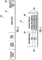
- FIG. 4 is an example of a message 400 including data 402 and an embedded error detection code 404 for data integrity monitoring in accordance with an example of the present disclosure.
- the embedded error detection code 404 is a frame check sequence.
- the error data reporting function 126 is also configured to create a network switch report message including the error data and to transmit the network switch report message to a network monitoring algorithm 132.
- the network monitoring algorithm 132 is configured to determine a data integrity of the particular link 110.
- the network monitoring algorithm 132 is embodied on and performed by a network node 108, for example, a network monitoring node 134 or 108n.
- a network monitoring node 134 is used in place of the general processing module 114 and network data integrity manager 112.
- each network switch 106 includes a processor circuit 124 and a memory 136 associated with the processor circuit 124.
- the memory 136 includes computer-readable program instructions 138 that, when executed by the processor circuit 124, cause the processor circuit 124 to perform a set of functions 140.
- An example of the set of functions will be described in more detail with reference to FIGS. 6A-6B .
- the set of functions 140 include the switching function 125 operable on the processor circuit 124.
- the switching function 125 is configured to selectively connect the network switch 106a to another network switch 106 or to a network node 108 of the plurality of network nodes 108a-108n.
- the set of functions 140 also include a network switch error data reporting function 126 operable on the network switch processor circuit 124.
- the set of functions 140 or error data reporting function 126 includes reading error data 128 from a switch interface 130 associated with a particular link 110 of the network 100.
- the set of functions 140 or the error data reporting function 126 also includes creating a network switch report message including the error data 128.
- the set of functions 140 or the error data reporting function 126 further include transmitting the network switch report message to a network monitoring algorithm 132.
- the network monitoring algorithm 132 is configured to determine a data integrity of the particular link 110 based on the error data.
- each network switch 106 also includes an error data counter 141. As described with reference to FIG. 7A , a count of the error data counter 141 associated with a particular link 110 is increased by one (1) in response to a message received by the network switch 106 including error data 128 or error data 128 being read from the switch interface 130. In the example in FIG. 1B , the error data counter 141 is stored in the memory 136 of the network switch 106.
- At least some network nodes 108 for example network node 108c in FIG. 1B , of the plurality of network nodes 108a-108n include a processor circuit 142 and a vehicle function 144 or functions operable on the network node processor circuit 142.
- the vehicle function 144 is configured to perform a particular function associated with the vehicle 104.
- the processor circuit 142 is the same type or similar to the processor circuit 124 of a network switch 106. In other examples, the processor circuit 142 is different from the processor circuit 124 of the network switch 106.
- the network node 108 also includes a network node error data reporting function 146 operable on the network node processor circuit 142.
- the network node error data reporting function 146 is configured to read error data 128 from a network interface 150 associated with a particular link 110 of the network 100.
- the error data reporting function 146 of the network node 108 is also configured to create a network node report message including the error data 128.
- the error data reporting function 146 of the network node 108 is further configured to transmit the network node report message to the network monitoring algorithm 132.
- the network monitoring algorithm 132 is configured to determine a data integrity of the particular link 110.
- each network node 108 includes a processor circuit 142 and a memory 152 associated with the processor circuit 142.
- the memory 152 includes computer-readable program instructions 154 that, when executed by the processor circuit 142, cause the processor circuit 142 to perform a set of functions 156.
- An example of the set of functions 156 will be described in more detail with reference to FIGS. 6A-6B .
- the set of functions 156 include one or more vehicle functions 144 and the error data reporting function 146.
- At least some network nodes 108 also include an error data counter 141. As described with reference to FIG. 8A, a count of the error data counter 141 associated with a particular link 110 is increased by one (1) in response to a message received by the network node 108 including error data 128 or error data 128 being read from the network interface 150. In the example in FIG. 1B , the error data counter 141 is stored in the memory 152 of the network node 108.
- the plurality of network nodes 108a-108n include a network monitoring node 134.
- the network monitoring node 134 includes a processor circuit 158 and the network monitoring algorithm 132 operable on the processor circuit 158.
- the processor circuit 158 may be the same or similar to processor circuits 124 and 142 or may be a different type processor circuit.
- the network monitoring node 134 also includes a memory 160 associated with the processor circuit 158.
- the memory 160 stores the network monitoring algorithm 132.
- the memory 160 also stores one or more vehicle functions 162 that are executed by the processor circuit 158.
- the memory 160 includes computer-readable program instructions 164 that, when executed by the processor circuit 158, cause the processor circuit 158 to perform a set of functions 166.
- An example of the set of functions 166 will be described in more detail with reference to FIGS. 6A-6B .
- the set of functions 156 optionally include one or more vehicle functions 162 and the network monitoring algorithm 132.
- the network monitoring node 134 also includes a configuration table 168 stored in the memory 160.
- FIG. 5 is an example of a configuration table 168 including an identification 502 of each link 110 of a plurality of links 110 of the network 100 and an error data threshold 504 associated with each link 110.
- the configuration table 168 includes a first column 506 of link identifications 502 and a second column 508 with an associated error data threshold 504.
- the configuration table 168 is configured to be used by the network monitoring algorithm 132 and/or undetectable corruption prediction algorithm 116 to determine if the error data 128 read from an interface 130 or 150 associated with a certain link 110 of the network 100 is greater than the error data threshold 504 for the certain link 110.
- FIG. 2 is a block schematic diagram of a network 200 including a system 202 for data integrity monitoring in accordance with another example of the present disclosure.
- the network 200 is a data network onboard a vehicle 104, such as an airplane or other vehicle or system.
- the network 200 is similar to the network 100 in FIGS. 1A and 1B except at least some or all network switches 106 in the network 200 are Aeronautical Radio, Incorporated (ARINC) remote switches 206, labeled as 206a-206n in FIG. 2 .
- the plurality of ARINC remote switches (ARSs) 206a-206n are configurable to selectively interconnect two or more network nodes 108, labeled as 108a-108n in FIG. 2 by links 110. At least some of the ARSs 206 and network nodes 108 are configured for data integrity monitoring or include features for data integrity monitoring similar to that previously described.
- Each ARS 206 includes a processor circuit 212 and a memory 214 associated with the processor circuit 212.
- the processor circuit 212 and the memory 214 are the same as the processor circuit 124 and memory 136 in FIG. 1B .
- the memory 214 includes computer-readable program instructions 216 that, when executed by the processor circuit 212, cause the processor circuit 212 to perform a set of functions 218. Examples of the set of functions 218 include a switching function 125 and a fault reporting function 220.
- the fault reporting function 220 includes reading error data 128 on a switch interface 130 associated with a particular link 110 and transmitting a message to a network data integrity manager 112 that there is a fault on the particular link 110. In some examples, the fault reporting function 220 is similar to that described in FIGS. 6A-6B or FIGS. 7A-7B .
- At least some ARSs 206 also include an error data counter 141. As described with reference to FIG. 7A , a count of the error data counter 141 associated with a particular link 110 is increased by one (1) in response to a message received by the ARS 206 including error data 128 or error data 128 being read from the switch interface 230. In the example in FIG. 2 , the error data counter 141 is stored in the memory 214 of the ARS 206.
- each ARS 206 also includes an ARINC 664 end system 222 connected to the processor circuit 212.
- the ARINC 664 end system 222 is configured to perform a particular function.
- the ARINC 664 end system 222 includes a network interface device that allows a network node 108 or a network switch 206 to transmit and receive on an ARINC 664 network 200.
- the ARINC 664 end system 222 handles ARINC 664 protocol elements and is essentially an enhanced Ethernet interface.
- ARINC 664 end systems 222 communicate with ARINC 664 switches 206, which police, filter, and route traffic to/from other ARINC end systems.
- each network node 108 is configured to perform one or more airplane functions 208.
- Each of the network nodes 108 is also configured to perform an error data reporting function 146 as previously described with reference to FIGS. 1A and 1B .
- the network 200 is coupled to a general processing module 114.
- a network data integrity manager 112 is embodied on the general processing module 114.
- the general processing module 114 and the network data integrity manager 112 are the same as that previously described with reference to FIG. 1A .
- the general processing module 114 is replaced by a network monitoring node, such as network monitoring node 134 or 108n in FIG. 1B .
- FIG. 3 is a flow chart of an example of a method 300 for creating a configuration table, such as configuration table 168, for data integrity monitoring in accordance with an example of the present disclosure.
- a configuration table 168 is illustrated in FIG. 5 .
- the method 300 is embodied on and performed by any system including a processor circuit and an associated memory similar to those described herein.
- the memory includes computer-readable program instructions that, when executed by the processor circuit, cause the processor circuit to perform the set of functions described with reference to blocks 302-310.
- the method 300 includes performing a network configuration process for a network, such as network 100 or 200, during design of a vehicle 104, such as an airplane or other type vehicle.
- the method 300 includes determining a data integrity level for each link 110 of the network 100 or 200. Determining the data integrity level includes determining an amount of error data 128 that is acceptable on a particular link 110.
- some network nodes 108 that perform more important or critical vehicle functions require a higher level of data integrity compared to other network nodes 108 that perform less important or less critical vehicle functions.
- Network nodes 108 and associated links 110 that perform more important or critical vehicle functions will have less tolerance for error data or corrupt data and will have a higher data integrity level compared to other network nodes 108 and associated links 110 that perform less important or critical vehicle functions.
- These network nodes 108 and associated links 110 will have a higher tolerance for corrupt data or error data or can accept a higher incidence of error data.
- the method 300 includes setting an error data threshold 504 for each link based on a data integrity level and characteristics of a particular link.
- the method 300 includes creating a configuration table 168 for a network monitoring algorithm, such as network monitoring algorithm 132 in FIG. 1B .
- the configuration table 168 includes identification 502 of each link 110 and an associated error data threshold 504.
- the method 300 includes loading the configuration table 168 on a network node 108, for example network monitoring node 134 in FIG. 1B .
- FIGS. 6A and 6B are a flow chart of an example of a method 600 for monitoring data integrity of a network 100 or 200 in accordance with an example of the present disclosure.
- a first portion 602 ( FIG. 6A ) of the method 600 is embodied in and performed by the network switches 106 and network nodes 108 in FIGS. 1A-1B and 2 .
- a second portion 616 ( FIG. 6B ) of the method 600 is embodied in and performed by the network data integrity manager 112 of the general processing module 114 ( FIG. 1A and FIG. 2 ) and/or the network monitoring node 134 ( FIG. 1B ).
- the error data reporting function 126 of the network switches 106 and the error data reporting function 146 of the network nodes 108 include the first portion 602 of the method 600.
- the undetectable corruption prediction algorithm 116 and/or the network monitoring algorithm 132 include the second portion 616 of the method 600.
- the method 600 includes activating an error data reporting function 126 in each network switch 106 and an error data reporting function 146 in each network node 108.
- the error data reporting function 126 or 146 is a periodic function, e.g., the error data reporting function 126 or 146 is performed at preset time intervals or for a preset time duration.
- the method 600 includes reading error data 128 from an interface (switch interface 130 or network interface 150) associated with a particular link 110 of the network 100 in response to error data 128 being present in a message, e.g., message 400 in FIG. 4 , received on the particular link 110.
- Reading the error data 128 includes reading the error data 128 from a switch interface 130 of a network switch 106 by an error data reporting function 126 operable on a processor circuit 124 of the network switch 106.
- Reading the error data 128 also includes reading the error data 128 from a network interface 150 of a network node 108 by an error data reporting function 146 operable on a processor circuit 142 of the network node 108.
- the method 600 in block 606 also includes using an embedded error detection method, such as cyclic redundancy cycles (CRCs) or frame check sequence (FCS) as previously described, to determine if a message includes error data 128.
- an embedded error detection method such as cyclic redundancy cycles (CRCs) or frame check sequence (FCS) as previously described, to determine if a message includes error data 128.
- CRCs cyclic redundancy cycles
- FCS frame check sequence
- the method 600 includes creating a report message 610 including at least the error data.
- the method 600 includes transmitting the report message 610 to a network monitoring algorithm 132 operable on a processor circuit 158.
- the network monitoring algorithm 132 is configured to determine a data integrity of the particular link 110 based on the error data 128. Transmitting the report message 610 includes transmitting the report message 610 by the error data reporting function 126 of a network switch 106 or transmitting the report message 610 by the error data reporting function 146 of a network node 108.
- the report message 610 is transmitted to a network monitoring node 134.
- the network monitoring node 134 includes the network monitoring algorithm 132.
- the report message 610 is transmitted to a network data integrity manager 112.
- the network data integrity manager 112 includes an undetectable corruption prediction algorithm 116.
- the undetectable corruption prediction algorithm 116 is configured to predict an amount of undetected corrupt data or a number of undetected messages including error data 128 that may have been transmitted over a particular link 110 based on a number of corrupt messages or number of messages including error data 128 that are actually detected by reading error data 128 from a switch interface 130 or a network interface 150.
- the periodic function of performing error data reporting ends.
- the method 600 may return to block 604 for activating the error data reporting function at a next preset time interval.
- monitoring the data integrity of the network 100 or 200 is performable on demand. In other examples, monitoring the data integrity of the network 100 or 200 is at preset time intervals.
- the method 600 includes receiving a report message 610, by a network monitoring node 134, for each link 110 of a plurality of links 110 of the network 100 or 200 having error data 128 on the link 110.
- the network monitoring node 134 includes the network monitoring algorithm 132.
- report messages 610 are receivable from an error data reporting function 126 of a network switch 106 or from an error data reporting function 146 of a network node 108.
- the method 600 includes receiving the report message 610 by a network data integrity manager 112 ( FIG. 1 and FIG. 2 ).
- the method 600 includes storing the report message 610 for each link 110 having error data 128.
- the method 600 includes running the network monitoring algorithm 132.
- the method 600 includes performing a data integrity analysis for each link 110 of the network 100 or 200 for which a report message 610 was received.
- performing the data integrity analysis includes blocks 626-634.
- the method 600 includes reading the error data 128 from a report message 610 for a particular link 110 for which a report message 610 was received.
- the method 600 includes determining the data integrity of the particular link 110 by determining if the error data 128 is greater than an error data threshold, e.g., error data threshold 504 in the configuration table 168 in FIG. 5 for the particular link 110.
- the data integrity of the particular link 110 is faulty in response to the error data 128 being greater than the error data threshold 504 for the particular link 110.
- the method 600 includes determining that the particular link 110 is faulty and performing a predetermined action in response to the particular link 110 being faulty.
- the predetermined action include but are not necessarily limited to shutting down the particular link 110, transmitting messages or data using another link 110 of the network until the particular link 110 is repaired or replace, and/or generating and transmitting a message indicating there is a fault on the particular link 110. The message is transmitted to a responsible entity for repairing or replacing of the faulty link.
- the method 600 includes determining if the particular link 110 is the last link or if there are other links for which a report message 610 was received. If the particular link 110 is not the last link, the method 600 returns to block 626 and the method 600 proceeds as previously described. If the particular link 110 is the last link, the method 600 advances to block 636. In block 636, the period function of monitoring the data integrity of the network 100 or 200 ends. Monitoring the data integrity of the network 100 or 200 is performable on demand or at periodic time intervals.
- FIGS. 7A and 7B are a flow chart of an example of a method 700 for monitoring data integrity of a network 100 or 200 in accordance with another example of the present disclosure.
- a first portion 702 ( FIG. 7A ) of the method 700 is embodied in and performed by the network switches 106 and network nodes 108 in FIGS. 1A-1B and 2 .
- a second portion 722 ( FIG. 7B ) of the method 700 is embodied in and performed by the network data integrity manager 112 of the general processing module 114 (network node 108a) and/or the network monitoring node 134 in FIG. 1B .
- the error data reporting function 126 of the network switches 106 and error data reporting function 146 of the network nodes 108 include the first portion 702 of the method 700.
- the undetectable corruption prediction algorithm 116 and the network monitoring algorithm 132 include the second portion 722 of the method 700.
- the method 700 includes receiving a message over a link 110 of the network 100 or 200.
- the message is received by one of a network switch 106 or a network node 108.
- the method 700 includes determining if the message includes error data 128.
- the method 700 includes using an embedded error detection method to determine if the message includes error data 128.
- An error detection code is embedded in the message for use in determining if the message includes error data 128. Examples of the embedded error detection code include a cyclic redundancy cycle, a frame check sequence, or other embedded error detection code.
- block 708 if the message does not include error data 128, the method 700 returns to block 704 and the method 700 repeats as previously described. If the message does include error data 128, the method 700 advances to block 710.
- the method 700 includes increasing a count of an error data counter 141 ( FIGS. 1B and 2 ) associated with the link 110 in response to the message including error data 128.
- the error data counter 141 is in a memory 136 of a network switch or a memory 152 of a network node 108.
- the count of the error data counter 141 associated with the particular link 110 is increased by one (1) in the memory of the network switch 106 or the network node 108 in response to the error data 128 being present in the message based on the embedded error detection method.
- the method 700 includes creating a report message 716 in response to the message or messages received by the network switch 106 or network node 108 including error data 128, or the error data counter 141 having a count greater than zero (0).
- the report message 716 includes the count of the error data counter 141.
- the report message 716 is created after the preset time interval expires.
- the report message 716 includes the count from the error data counter 141 of the network switch 106 or the network node 108.
- the method 700 includes transmitting the report message 716 to a network data integrity manager 112 to determine whether the link 110 has a fault.
- the report message 716 is transmitted to a network monitoring node 134.
- the method 700 includes transmitting the report message 716 by an error data reporting function 126 of the network switch 106, or an error data reporting function 146 the network node 108, depending upon which received the message or messages including the error data 128.
- the network data integrity manager 112 is configured to determine a probability of undetected corrupt messages being transmitted by a particular link 110 using the count from the error data counter 141 associated with the particular link 110.
- the method 700 includes resetting the error data counter 141 associated with a link 110 to zero (0) in response to transmitting the report message 716 to a network data integrity manager 112 or a network monitoring node 134.
- the method 700 returns to block 704, in response to transmitting the report message 716 and/or resetting the error data counter 141, for receiving additional messages over the link 110 by the associated network switch 106 or associated network node 108.
- the method 700 includes receiving the report message 716 by the network data integrity manager 112 or network monitoring node 134 from the network switch 106 or the network node 108.
- the report message 716 includes the count from the error data counter 141 of the network switch 106 or the network node 108.
- the method 700 includes adding the count of the error data counter 141 to a count of a corrupted data counter 122 or using the count in the network monitoring algorithm 132 of a network monitoring node 134 to determine the data integrity of a particular link 110.
- the method 700 includes comparing the count of the corrupted data counter 122 to an error data threshold 504 for the link 110. In block 730, if the count of the corrupted data counter 122 is not greater than the error data threshold 504 for the link 110, the method 700 advances to block 732. In block 732, no action is taken. If the count of the corrupted data counter 122 is greater than the error data threshold 504 for the link, the method 700 advances to block 734.
- the method 700 includes determining a probability of undetected corrupt messages being transmitted by the link 110 using the count of the corrupted data counter 122.
- the undetectable corruption prediction algorithm 116 is configured to determine the probability of undetected corrupt messages being transmitted by the link 110 using the count of the corrupted data counter 122.
- the method 700 includes determining the link 110 has a fault in response to the count of the corrupted data counter 122 being greater than the error data threshold 504 for the link 110.
- the method 700 also includes transmitting a message that a probability of undetected corruption on the link 110 has exceeded a design value in response to the count of the corrupted data counter 122 being greater than the error data threshold 504 for the link 110.
- the message is transmitted to a responsible entity for performing a predetermined action.
- the method 700 includes performing a predetermined action with respect to the faulty link 110. Similar to that previously described, examples of the predetermined action include shutting down the faulty link 110, transmitting messages via another link, or other predetermined action.
- the computer-readable program instructions are embodied in a computer program product that is similar to or the same as that described herein.
- the computer-readable program instructions are downloaded by a processor circuit and stored on the memory associated with the processor circuit.
- each block in the flowchart or block diagrams may represent a module, segment, or portion of instructions, which comprises one or more executable instructions for implementing the specified logical function(s).
- the functions noted in the block may occur out of the order noted in the figures.
- two blocks shown in succession may, in fact, be executed substantially concurrently, or the blocks may sometimes be executed in the reverse order, depending upon the functionality involved.
Landscapes
- Engineering & Computer Science (AREA)
- Computer Networks & Wireless Communication (AREA)
- Signal Processing (AREA)
- Environmental & Geological Engineering (AREA)
- Computer Security & Cryptography (AREA)
- Data Mining & Analysis (AREA)
- Computer Hardware Design (AREA)
- Computing Systems (AREA)
- General Engineering & Computer Science (AREA)
- Data Exchanges In Wide-Area Networks (AREA)
Abstract
Description
- The present disclosure relates to data communications and networks and more particularly to a network including data integrity monitoring.
- Networks for communicating data, such as a data network onboard an airplane or other system, specify a probability of undetected erroneous data that is allowable for continued operation of the airplane or system. Possible types of corruption on data networks include message impersonation, ordinal integrity violation, excessive or increased latency, and data corruption. There is some probability of corruption from a line replaceable unit (LRU) or physical layer causes, such as electromagnetic emissions, vibration, dirty fiber optics, etc. Data integrity monitoring on a network, particularly a data network onboard an airplane, is important for corrective action to be taken and to avoid or minimize grounding of the airplane.
- In accordance with an example, a method for monitoring data integrity on a network includes reading error data from an interface associated with a particular link of the network in response to error data being present in a message received on the particular link. The method also includes creating a report message including the error data and transmitting the report message to a network monitoring algorithm operable on a processor circuit. The network monitoring algorithm is configured to determine a data integrity of the particular link based on the error data.
- In accordance with an example and any of the preceding examples, a method for monitoring data integrity on a network includes receiving a message over a link of the network by a network switch or a network node. The method also includes determining if the message includes error data and creating a report message in response to the message including error data. The method additionally includes transmitting the report message to a network data integrity manager to determine whether the link has a fault.
- In accordance with another example and any of the preceding examples, a network including data integrity monitoring comprises a plurality of network switches. The plurality of network switches are configurable to selectively interconnect two or more network nodes from a plurality of network nodes. Each network switch includes a network switch processor circuit and a switching function operable on the network switch processor circuit. The switching function is configured to selectively connect the network switch to another network switch or a network node from the plurality of network nodes. Each network switch also includes a network switch error data reporting function operable on the network switch processor circuit and configured to: read error data from a switch interface associated with a particular link of the network; create a network switch report message including the error data; and transmit the network switch report message to a network monitoring algorithm. The network monitoring algorithm is configured to determine a data integrity of the particular link.
- In accordance with an example and any of the preceding examples, the method and network further include determining the data integrity of the particular link by determining if the error data is greater than an error data threshold for the particular link. The data integrity of the particular link is faulty in response to the error data being greater than the error data threshold. The method and network further include performing a predetermined action in response to the particular link being faulty.
- In accordance with an example and any of the preceding examples, wherein the predetermined action includes at least one of: shutting down the particular link; or transmitting data using another link of the network until the particular link is repaired.
- In accordance with an example and any of the preceding examples, wherein said reading the error data includes reading the error data from a network interface of a network node by an error data reporting function operable on a processor circuit of the network node, and wherein said transmitting the report message includes transmitting the report message by the error data reporting function of the network node.
- In accordance with an example and any of the preceding examples, wherein said reading the error data includes reading the error data from a switch interface of a network switch by an error data reporting function operable on a processor circuit of the network switch, and wherein said transmitting the report message includes transmitting the report message by the error data reporting function of the network switch.
- In accordance with an example and any of the preceding examples, the method and network further include receiving a particular report message, by a network monitoring node, for each link, from a plurality of links of the network, having error data on the link. The network monitoring node includes the network monitoring algorithm. The method and network further include reading the error data from the particular report message for each link and determining a data integrity of each link by determining if the error data is greater than an error data threshold for each link. The data integrity for the link is faulty in response to the error data being greater than the error data threshold. The method and network further include performing a predetermined action in response to the link being faulty.
- In accordance with an example and any of the preceding examples, the method and network further include receiving the message over the particular link, wherein the message is received by one of a network switch or a network node. The method and network further include determining if the message includes the error data by using an embedded error detection method. The method and network further include increasing a count of an error data counter associated with the particular link by one (1) in a memory of the network switch or the network node in response to the error data being present based on the embedded error detection method. The report message is created after a preset time interval expires and the report message includes the count from the error data counter.
- In accordance with an example and any of the preceding examples, the method and network further include transmitting the report message by an error data reporting function of the network switch or the network node that received the message, to a network data integrity manager. The network data integrity manager is configured to determine a probability of undetected corrupt messages being transmitted by the particular link using the count from the error data counter.
- In accordance with an example and any of the preceding examples, the method and network further include using an embedded error detection method to determine if the message comprises error data.
- In accordance with an example and any of the preceding examples, the method and network further include increasing a count of an error data counter associated with the link in response to the message including error data.
- In accordance with an example and any of the preceding examples, the method and network further include allowing one or more additional messages to be received over the link in response to a preset time interval not having expired; and increasing the count of the error data counter for each additional message that includes error data.
- In accordance with an example and any of the preceding examples, the report message includes the count of the error data counter.
- In accordance with an example and any of the preceding examples, the method and network further include adding the count of the error data counter to a count of a corrupted data counter; comparing the count of the corrupted data counter to an error data threshold for the link; and determining that the link has a fault in response to the count of the corrupted data counter being greater than the error data threshold for the link.
- In accordance with an example and any of the preceding examples, the method and network further including determining a probability of undetected corrupt messages being transmitted by the link using the count of the corrupted data counter; and transmitting a message that a probability of undetected corruption on the link has exceeded a design value in response to the count of the corrupted data counter being greater than the error data threshold for the link.
- In accordance with an example and any of the preceding examples, wherein at least some network nodes from the plurality of network nodes include a network node processor circuit; and a vehicle function operable on the network node processor circuit and configured to perform a particular function associated with a vehicle. At least some network nodes from the plurality of network nodes further include a network node error data reporting function operable on the network node processor circuit and configured to: read error data from a network interface associated with another particular link of the network; create a network node report message including the error data; and transmit the network node report message to the network monitoring algorithm, wherein the network monitoring algorithm is configured to determine a data integrity of the other particular link.
- In accordance with an example and any of the preceding examples, wherein the method and network further include a network monitoring node of the plurality of network nodes. The network monitoring node includes a processor circuit; the network monitoring algorithm operable on the processor circuit; a memory associated with the processor circuit; and a configuration table stored in the memory. The configuration table includes an identification of each link from a plurality of links of the network and an error data threshold associated with each link. The configuration table is configured to be used by the network monitoring algorithm to determine if the error data read from an interface associated with a certain link of the network is greater than the error data threshold for the certain link.
- In accordance with an example and any of the preceding examples, wherein the network monitoring node is configured to perform a set of functions including: receiving a particular report message for each link from a plurality of links of the network having error data on the link; reading the error data from the particular report message for each link; determining a data integrity of each link by determining if the error data is greater than an error data threshold for each link, wherein the data integrity for the link is faulty in response to the error data being greater than the error data threshold; and performing a predetermined action in response to the link being faulty.
- In accordance with an example and any of the preceding examples, wherein the network further includes a network data integrity manager. The network data integrity manager includes a processor circuit and a memory associated with the processor circuit. The memory includes computer-readable program instructions that, when executed by the processor circuit, cause the processor circuit to perform a set of functions including receiving a report error message comprising a count from an error data counter associated with a certain link. The count of the error data counter is increased in response to each message received over the particular link that includes error data. The set of functions also include adding the count of the error data counter to a count of a corrupted data counter. The set of functions further include comparing the count of the corrupted data counter to an error data threshold for the particular link and determining that the particular link has a fault in response to the count of the corrupted data counter being greater than the error data threshold for the particular link.
- In accordance with an example, a network device, comprised in a network switch of a plurality of network switched (106) or in a network node of a plurality of network nodes (108), wherein the plurality of network switches (106) are configurable to selectively interconnect two or more network nodes (108) from the plurality of network nodes (108), comprises a processor and a memory associated with the processor, wherein the processor is configured to implement a method (700) for monitoring data integrity on a network (100, 200), the method comprising: receiving (704) a message (400) over a link (110) of the network (100, 200) by a network switch (106) or a network node (108); determining (706) if the message (400) comprises error data (128); creating (714) a report message (716) in response to the message (400) comprising error data (128); and transmitting (718) the report message (716) to a network data integrity manager (112) to determine whether the link (110) has a fault.
- In accordance with an example and the preceding example, the method further comprises: using (706) an embedded error detection method to determine if the message (400) comprises error data (128).
- The features, functions, and advantages that have been discussed can be achieved independently in various examples or may be combined in yet other examples further details of which can be seen with reference to the following description and drawings.
-
-
FIG. 1A is a block schematic diagram of an example of a network including data integrity monitoring in accordance with an example of the present disclosure. -
FIG. 1B is a block schematic diagram of the exemplary network inFIG. 1A including examples of a network switch and network nodes configured for data integrity monitoring in accordance with an example of the present disclosure. -
FIG. 2 is a block schematic diagram of a network including a system for data integrity monitoring in accordance with another example of the present disclosure. -
FIG. 3 is a flow chart of an example of a method for creating a configuration table for data integrity monitoring in accordance with an example of the present disclosure. -
FIG. 4 is an example of a message including data and an embedded error detection code for data integrity monitoring in accordance with an example of the present disclosure. -
FIG. 5 is an example of a configuration table including an identification of each link of a plurality of links of a network and an error data threshold associated with each link in accordance with an example of the present disclosure. -
FIGS. 6A and6B are a flow chart of an example of a method for monitoring data integrity of a network in accordance with an example of the present disclosure. -
FIGS. 7A and7B are a flow chart of an example of a method for monitoring data integrity of a network in accordance with another example of the present disclosure. - The following detailed description of embodiments refers to the accompanying drawings, which illustrate specific embodiments of the disclosure. Other embodiments having different structures and operations do not depart from the scope of the present disclosure. Like reference numerals may refer to the same element or component in the different drawings.
- The present disclosure may be a system, a method, and/or a computer program product. The computer program product may include a computer-readable storage medium (or media) having computer-readable program instructions thereon for causing a processor to carry out aspects of the present disclosure.
- The computer-readable storage medium can be a tangible device that can retain and store instructions for use by an instruction execution device. The computer-readable storage medium may be, for example, but is not limited to, an electronic storage device, a magnetic storage device, an optical storage device, an electromagnetic storage device, a semiconductor storage device, or any suitable combination of the foregoing. A non-exhaustive list of more specific examples of the computer-readable storage medium includes the following: a portable computer diskette, a hard disk, a random access memory (RAM), a read-only memory (ROM), an erasable programmable read-only memory (EPROM or Flash memory), a static random access memory (SRAM), a portable compact disc read-only memory (CD-ROM), a digital versatile disk (DVD), a memory stick, a floppy disk, a mechanically encoded device such as punch-cards or raised structures in a groove having instructions recorded thereon, and any suitable combination of the foregoing. A computer-readable storage medium, as used herein, is not to be construed as being transitory signals per se, such as radio waves or other freely propagating electromagnetic waves, electromagnetic waves propagating through a waveguide or other transmission media (e.g., light pulses passing through a fiber-optic cable), or electrical signals transmitted through a wire.
- Computer-readable program instructions described herein can be downloaded to respective computing/processing devices from a computer-readable storage medium or to an external computer or external storage device via a network, for example, the Internet, a local area network, a wide area network and/or a wireless network. The network may comprise copper transmission cables, optical transmission fibers, wireless transmission, routers, firewalls, switches, gateway computers and/or edge servers. A network adapter card or network interface in each computing/processing device receives computer-readable program instructions from the network and forwards the computer-readable program instructions for storage in a computer-readable storage medium within the respective computing/processing device.
- Computer-readable program instructions for carrying out operations of the present disclosure may be assembler instructions, instruction-set-architecture (ISA) instructions, machine instructions, machine dependent instructions, microcode, firmware instructions, state-setting data, or either source code or object code written in any combination of one or more programming languages, including an object oriented programming language such as Smalltalk, C++ or the like, and conventional procedural programming languages, such as the "C" programming language or similar programming languages. The computer-readable program instructions may execute entirely on the user's computer, partly on the user's computer, as a stand-alone software package, partly on the user's computer and partly on a remote computer or entirely on the remote computer or server. In the latter scenario, the remote computer may be connected to the user's computer through any type of network, including a local area network (LAN) or a wide area network (WAN), or the connection may be made to an external computer (for example, through the Internet using an Internet Service Provider). In some embodiments, electronic circuitry including, for example, programmable logic circuitry, field-programmable gate arrays (FPGA), or programmable logic arrays (PLA) may execute the computer-readable program instructions by utilizing state information of the computer-readable program instructions to personalize the electronic circuitry, in order to perform aspects of the present disclosure.
- Aspects of the present disclosure are described herein with reference to flowchart illustrations and/or block diagrams of methods, apparatus (systems), and computer program products according to embodiments of the disclosure. It will be understood that each block of the flowchart illustrations and/or block diagrams, and combinations of blocks in the flowchart illustrations and/or block diagrams, can be implemented by computer-readable program instructions.
- These computer-readable program instructions may be provided to a processor of a general purpose computer, special purpose computer, or other programmable data processing apparatus to produce a machine, such that the instructions, which execute via the processor of the computer or other programmable data processing apparatus, create means for implementing the functions/acts specified in the flowchart and/or block diagram block or blocks. These computer-readable program instructions may also be stored in a computer-readable storage medium that can direct a computer, a programmable data processing apparatus, and/or other devices to function in a particular manner, such that the computer-readable storage medium having instructions stored therein comprises an article of manufacture including instructions which implement aspects of the function/act specified in the flowchart and/or block diagram block or blocks.
- The computer-readable program instructions may also be loaded onto a computer, other programmable data processing apparatus, or other device to cause a series of operational steps to be performed on the computer, other programmable apparatus or other device to produce a computer implemented process, such that the instructions which execute on the computer, other programmable apparatus, or other device implement the functions/acts specified in the flowchart and/or block diagram block or blocks.
-
FIG. 1A is a block schematic diagram of an example of anetwork 100 including data integrity monitoring in accordance with an example of the present disclosure. In accordance with an example, thenetwork 100 is a data network onboard avehicle 104, such as an airplane or other vehicle or system. Thenetwork 100 includes a plurality of network switches 106 labeled as 106a-106n inFIG. 1A . The plurality ofnetwork switches 106a-106n are configurable to selectively interconnect two or more network nodes 108, labeled as 108a-108n inFIG. 1A bylinks 110. As described in more detail with reference toFIG. 1B , at least some of the network switches 106 and network nodes 108 are configured for data integrity monitoring or include features for data integrity monitoring. Additionally, in accordance with some examples, a networkdata integrity manager 112 is configured to monitor data integrity. An example of a method for monitoring data integrity on a network that is performable by the networkdata integrity manager 112 will be described in more detail with reference toFIGS. 7A and7B . - In accordance with the example in
FIG. 1A , the networkdata integrity manager 112 is embodied in ageneral processing module 114. In some examples, thegeneral processing module 114 is also anetwork node 108a. The networkdata integrity manager 112 is configured to monitor data integrity on thenetwork 100, as described in more detail herein, and perform a predetermined action or actions in response to detecting error data on alink 110 associated with a particular network switch 106 or network node 108. Examples of the predetermined action include, but are not necessarily limited to, shutting down theparticular link 110, transmitting messages or data via analternate link 110, and/or generating and transmitting a message indicating there is a fault on theparticular link 110. The message is transmitted to a responsible entity, so that thelink 110 can be repaired or replaced. Possible causes of error data on alink 110 include message impersonation, ordinal integrity violation, excessive or increased latency, and data corruption. Additionally, corruption or error data can be caused by a line replaceable unit (LRU) in thenetwork 100 or a physical layer, such as electromagnetic emissions, vibration, dirty fiber optics, etc. - In the example in
FIG. 1 , the networkdata integrity manager 112 includes an undetectablecorruption prediction algorithm 116. The undetectablecorruption prediction algorithm 116 is configured to predict an amount of undetected corrupt data or a number of undetected messages includingerror data 128 that may have been transmitted over aparticular link 110 based on a number of corrupt messages or number of messages including error data that are detected. Corrupt data and error data have the same meaning and may be used interchangeably herein. In one example, the undetectablycorruption prediction algorithm 116 is configured to predict an amount of undetected corrupt data or a number of undetected messages includingerror data 128 by using network traffic quantity or rate information, message sizes, and link speed combined with mathematical error models for how many error patterns are detected by a Frame Check Sequence's CRC (or other protection methods) versus how many go undetected. In some examples, a configuration table 168 (FIG. 2 ) also includes the network traffic quantity or rate information, message sizes and link speed for eachlink 110. - In the example illustrated in
FIG. 1A , thegeneral processing module 114 or networkdata integrity manager 112 includes aprocessor circuit 118 and an associatedmemory 119. Thememory 119 includes computer-readable program instructions 120 that, when executed by theprocessor circuit 118, cause theprocessor circuit 118 to perform a set offunctions 121. An example of the set offunctions 121 includes the undetectablecorruption prediction algorithm 116. - The network
data integrity manager 112 also includes a corrupteddata counter 122. As described in more detail herein with reference toFIGS. 7A and7B , a count of the corrupteddata counter 122 is compared to a preset data threshold for aparticular link 110. If the count is less than or equal the preset threshold, no action is taken. If the count is greater than the preset threshold, the undetectablecorruption prediction algorithm 116 uses the count from the corrupteddata counter 122 to determine a probability of undetected corrupt messages being transmitted by theparticular link 110. The networkdata integrity manager 112 performs the predetermined action in response to the count being greater than the preset threshold. The preset threshold is adjustable for eachlink 110 to tune the data integrity monitoring of thenetwork 100. For example, some network nodes 108 that perform more important or critical vehicle functions require a higher level of data integrity compared to other network nodes 108 that perform less important or less critical vehicle functions. Network nodes 108 and associatedlinks 110 that perform more important or critical vehicle functions will have less tolerance for corrupt data or messages and will have a lower preset threshold compared to other network nodes 108 and associatedlinks 110 that perform less important or critical vehicle functions. These network nodes 108 and associatedlinks 110 will have a higher tolerance for corrupt data or messages or can accept a higher incidence of corrupt data or messages and will have a corresponding higher preset threshold. - Referring to
FIG. 1B, FIG. 1B is a block schematic diagram of theexemplary network 100 inFIG. 1A including examples of a network switch 106 and network nodes 108 configured for data integrity monitoring in accordance with an example of the present disclosure. As previously described, thenetwork 100 includes a plurality ofnetwork switches 106a-106n. The plurality ofnetwork switches 106a-106n are configurable to selectively interconnect two ormore network nodes 108a-108n of the plurality ofnetwork nodes 108a-108n. Each network switch 106 includes a networkswitch processor circuit 124 and aswitching function 125 operable on theprocessor circuit 124 and configured to selectively connect the network switch 106 to another network switch 106 or to a network node 108 of the plurality ofnetwork nodes 108a-108n. - Each network switch 106 also includes a network switch error
data reporting function 126 operable on the networkswitch processor circuit 124. The errordata reporting function 126 is configured to readerror data 128 from aswitch interface 130 associated with aparticular link 110 of thenetwork 100. In some examples, reading error data from aswitch interface 130 includes using an embedded error detection method to determine if a message received by theswitch interface 130 includeserror data 128. Examples of embedded error detection methods include, but are not necessarily limited to, cyclic redundancy checks (CRCs) embedded in a message and a frame check sequence (FCS) embedded in the message. Referring also toFIG. 4, FIG. 4 is an example of amessage 400 includingdata 402 and an embeddederror detection code 404 for data integrity monitoring in accordance with an example of the present disclosure. In theexample message 400 inFIG. 4 , the embeddederror detection code 404 is a frame check sequence. - The error
data reporting function 126 is also configured to create a network switch report message including the error data and to transmit the network switch report message to a network monitoring algorithm 132. The network monitoring algorithm 132 is configured to determine a data integrity of theparticular link 110. In accordance with the example illustrated inFIG. 1B , the network monitoring algorithm 132 is embodied on and performed by a network node 108, for example, anetwork monitoring node network monitoring node 134 is used in place of thegeneral processing module 114 and networkdata integrity manager 112. - In accordance with some examples, each network switch 106 includes a
processor circuit 124 and amemory 136 associated with theprocessor circuit 124. Thememory 136 includes computer-readable program instructions 138 that, when executed by theprocessor circuit 124, cause theprocessor circuit 124 to perform a set offunctions 140. An example of the set of functions will be described in more detail with reference toFIGS. 6A-6B . In the example in FIG. 2B, the set offunctions 140 include theswitching function 125 operable on theprocessor circuit 124. Theswitching function 125 is configured to selectively connect thenetwork switch 106a to another network switch 106 or to a network node 108 of the plurality ofnetwork nodes 108a-108n. - The set of
functions 140 also include a network switch errordata reporting function 126 operable on the networkswitch processor circuit 124. In some examples, the set offunctions 140 or errordata reporting function 126 includes readingerror data 128 from aswitch interface 130 associated with aparticular link 110 of thenetwork 100. The set offunctions 140 or the errordata reporting function 126 also includes creating a network switch report message including theerror data 128. The set offunctions 140 or the errordata reporting function 126 further include transmitting the network switch report message to a network monitoring algorithm 132. The network monitoring algorithm 132 is configured to determine a data integrity of theparticular link 110 based on the error data. - In accordance with some examples, each network switch 106 also includes an
error data counter 141. As described with reference toFIG. 7A , a count of the error data counter 141 associated with aparticular link 110 is increased by one (1) in response to a message received by the network switch 106 includingerror data 128 orerror data 128 being read from theswitch interface 130. In the example inFIG. 1B , the error data counter 141 is stored in thememory 136 of the network switch 106. - At least some network nodes 108, for
example network node 108c inFIG. 1B , of the plurality ofnetwork nodes 108a-108n include aprocessor circuit 142 and avehicle function 144 or functions operable on the networknode processor circuit 142. Thevehicle function 144 is configured to perform a particular function associated with thevehicle 104. In some examples, theprocessor circuit 142 is the same type or similar to theprocessor circuit 124 of a network switch 106. In other examples, theprocessor circuit 142 is different from theprocessor circuit 124 of the network switch 106. - The network node 108 also includes a network node error
data reporting function 146 operable on the networknode processor circuit 142. The network node errordata reporting function 146 is configured to readerror data 128 from anetwork interface 150 associated with aparticular link 110 of thenetwork 100. The errordata reporting function 146 of the network node 108 is also configured to create a network node report message including theerror data 128. The errordata reporting function 146 of the network node 108 is further configured to transmit the network node report message to the network monitoring algorithm 132. As previously described, the network monitoring algorithm 132 is configured to determine a data integrity of theparticular link 110. - In accordance with some examples, each network node 108 includes a
processor circuit 142 and amemory 152 associated with theprocessor circuit 142. Thememory 152 includes computer-readable program instructions 154 that, when executed by theprocessor circuit 142, cause theprocessor circuit 142 to perform a set offunctions 156. An example of the set offunctions 156 will be described in more detail with reference toFIGS. 6A-6B . In the example inFIG. 1B , the set offunctions 156 include one or more vehicle functions 144 and the errordata reporting function 146. - In accordance with some examples, at least some network nodes 108 also include an
error data counter 141. As described with reference to FIG. 8A, a count of the error data counter 141 associated with aparticular link 110 is increased by one (1) in response to a message received by the network node 108 includingerror data 128 orerror data 128 being read from thenetwork interface 150. In the example inFIG. 1B , the error data counter 141 is stored in thememory 152 of the network node 108. - In some examples, the plurality of
network nodes 108a-108n include anetwork monitoring node 134. Thenetwork monitoring node 134 includes aprocessor circuit 158 and the network monitoring algorithm 132 operable on theprocessor circuit 158. Theprocessor circuit 158 may be the same or similar toprocessor circuits - The
network monitoring node 134 also includes amemory 160 associated with theprocessor circuit 158. In the example inFIG. 1B , thememory 160 stores the network monitoring algorithm 132. In some examples, thememory 160 also stores one or more vehicle functions 162 that are executed by theprocessor circuit 158. Thememory 160 includes computer-readable program instructions 164 that, when executed by theprocessor circuit 158, cause theprocessor circuit 158 to perform a set offunctions 166. An example of the set offunctions 166 will be described in more detail with reference toFIGS. 6A-6B . In the example inFIG. 1B , the set offunctions 156 optionally include one or more vehicle functions 162 and the network monitoring algorithm 132. - In some examples, the
network monitoring node 134 also includes a configuration table 168 stored in thememory 160. Referring also toFIG. 5, FIG. 5 is an example of a configuration table 168 including anidentification 502 of each link 110 of a plurality oflinks 110 of thenetwork 100 and anerror data threshold 504 associated with eachlink 110. In the example inFIG. 5 , the configuration table 168 includes afirst column 506 oflink identifications 502 and asecond column 508 with an associatederror data threshold 504. The configuration table 168 is configured to be used by the network monitoring algorithm 132 and/or undetectablecorruption prediction algorithm 116 to determine if theerror data 128 read from aninterface certain link 110 of thenetwork 100 is greater than theerror data threshold 504 for thecertain link 110. -
FIG. 2 is a block schematic diagram of anetwork 200 including asystem 202 for data integrity monitoring in accordance with another example of the present disclosure. In accordance with an example, thenetwork 200 is a data network onboard avehicle 104, such as an airplane or other vehicle or system. Thenetwork 200 is similar to thenetwork 100 inFIGS. 1A and1B except at least some or all network switches 106 in thenetwork 200 are Aeronautical Radio, Incorporated (ARINC) remote switches 206, labeled as 206a-206n inFIG. 2 . The plurality of ARINC remote switches (ARSs) 206a-206n are configurable to selectively interconnect two or more network nodes 108, labeled as 108a-108n inFIG. 2 bylinks 110. At least some of the ARSs 206 and network nodes 108 are configured for data integrity monitoring or include features for data integrity monitoring similar to that previously described. - Each ARS 206 includes a
processor circuit 212 and amemory 214 associated with theprocessor circuit 212. In some examples, theprocessor circuit 212 and thememory 214 are the same as theprocessor circuit 124 andmemory 136 inFIG. 1B . Thememory 214 includes computer-readable program instructions 216 that, when executed by theprocessor circuit 212, cause theprocessor circuit 212 to perform a set offunctions 218. Examples of the set offunctions 218 include aswitching function 125 and afault reporting function 220. Thefault reporting function 220 includes readingerror data 128 on aswitch interface 130 associated with aparticular link 110 and transmitting a message to a networkdata integrity manager 112 that there is a fault on theparticular link 110. In some examples, thefault reporting function 220 is similar to that described inFIGS. 6A-6B orFIGS. 7A-7B . - In some examples, at least some ARSs 206 also include an
error data counter 141. As described with reference toFIG. 7A , a count of the error data counter 141 associated with aparticular link 110 is increased by one (1) in response to a message received by the ARS 206 includingerror data 128 orerror data 128 being read from theswitch interface 230. In the example inFIG. 2 , the error data counter 141 is stored in thememory 214 of the ARS 206. - In some examples, each ARS 206 also includes an
ARINC 664end system 222 connected to theprocessor circuit 212. TheARINC 664end system 222 is configured to perform a particular function. TheARINC 664end system 222 includes a network interface device that allows a network node 108 or a network switch 206 to transmit and receive on anARINC 664network 200. TheARINC 664end system 222 handlesARINC 664 protocol elements and is essentially an enhanced Ethernet interface.ARINC 664end systems 222 communicate withARINC 664 switches 206, which police, filter, and route traffic to/from other ARINC end systems. - In accordance with an example where the
vehicle 104 is an airplane, each network node 108 is configured to perform one or more airplane functions 208. Each of the network nodes 108 is also configured to perform an errordata reporting function 146 as previously described with reference toFIGS. 1A and1B . - In some examples, as illustrated in
FIG. 2 , thenetwork 200 is coupled to ageneral processing module 114. A networkdata integrity manager 112 is embodied on thegeneral processing module 114. In accordance with an example, thegeneral processing module 114 and the networkdata integrity manager 112 are the same as that previously described with reference toFIG. 1A . In other examples, thegeneral processing module 114 is replaced by a network monitoring node, such asnetwork monitoring node FIG. 1B . -
FIG. 3 is a flow chart of an example of amethod 300 for creating a configuration table, such as configuration table 168, for data integrity monitoring in accordance with an example of the present disclosure. As previously described, an example of a configuration table 168 is illustrated inFIG. 5 . In accordance with an example, themethod 300 is embodied on and performed by any system including a processor circuit and an associated memory similar to those described herein. The memory includes computer-readable program instructions that, when executed by the processor circuit, cause the processor circuit to perform the set of functions described with reference to blocks 302-310. - In
block 302, themethod 300 includes performing a network configuration process for a network, such asnetwork vehicle 104, such as an airplane or other type vehicle. - In
block 304, themethod 300 includes determining a data integrity level for eachlink 110 of thenetwork error data 128 that is acceptable on aparticular link 110. As previously described, some network nodes 108 that perform more important or critical vehicle functions require a higher level of data integrity compared to other network nodes 108 that perform less important or less critical vehicle functions. Network nodes 108 and associatedlinks 110 that perform more important or critical vehicle functions will have less tolerance for error data or corrupt data and will have a higher data integrity level compared to other network nodes 108 and associatedlinks 110 that perform less important or critical vehicle functions. These network nodes 108 and associatedlinks 110 will have a higher tolerance for corrupt data or error data or can accept a higher incidence of error data. - In
block 306, themethod 300 includes setting anerror data threshold 504 for each link based on a data integrity level and characteristics of a particular link. - In
block 308, themethod 300 includes creating a configuration table 168 for a network monitoring algorithm, such as network monitoring algorithm 132 inFIG. 1B . The configuration table 168 includesidentification 502 of eachlink 110 and an associatederror data threshold 504. - In
block 310, themethod 300 includes loading the configuration table 168 on a network node 108, for examplenetwork monitoring node 134 inFIG. 1B . -
FIGS. 6A and6B are a flow chart of an example of amethod 600 for monitoring data integrity of anetwork FIG. 6A ) of themethod 600 is embodied in and performed by the network switches 106 and network nodes 108 inFIGS. 1A-1B and2 . A second portion 616 (FIG. 6B ) of themethod 600 is embodied in and performed by the networkdata integrity manager 112 of the general processing module 114 (FIG. 1A andFIG. 2 ) and/or the network monitoring node 134 (FIG. 1B ). For example, the errordata reporting function 126 of the network switches 106 and the errordata reporting function 146 of the network nodes 108 include thefirst portion 602 of themethod 600. The undetectablecorruption prediction algorithm 116 and/or the network monitoring algorithm 132 include thesecond portion 616 of themethod 600. - In
block 604, themethod 600 includes activating an errordata reporting function 126 in each network switch 106 and an errordata reporting function 146 in each network node 108. In some examples the errordata reporting function data reporting function - In
block 606, themethod 600 includes readingerror data 128 from an interface (switchinterface 130 or network interface 150) associated with aparticular link 110 of thenetwork 100 in response toerror data 128 being present in a message, e.g.,message 400 inFIG. 4 , received on theparticular link 110. Reading theerror data 128 includes reading theerror data 128 from aswitch interface 130 of a network switch 106 by an errordata reporting function 126 operable on aprocessor circuit 124 of the network switch 106. Reading theerror data 128 also includes reading theerror data 128 from anetwork interface 150 of a network node 108 by an errordata reporting function 146 operable on aprocessor circuit 142 of the network node 108. - The
method 600 inblock 606 also includes using an embedded error detection method, such as cyclic redundancy cycles (CRCs) or frame check sequence (FCS) as previously described, to determine if a message includeserror data 128. - In
block 608, themethod 600 includes creating areport message 610 including at least the error data. - In
block 612, themethod 600 includes transmitting thereport message 610 to a network monitoring algorithm 132 operable on aprocessor circuit 158. The network monitoring algorithm 132 is configured to determine a data integrity of theparticular link 110 based on theerror data 128. Transmitting thereport message 610 includes transmitting thereport message 610 by the errordata reporting function 126 of a network switch 106 or transmitting thereport message 610 by the errordata reporting function 146 of a network node 108. - In some examples, the
report message 610 is transmitted to anetwork monitoring node 134. Thenetwork monitoring node 134 includes the network monitoring algorithm 132. In other examples, thereport message 610 is transmitted to a networkdata integrity manager 112. The networkdata integrity manager 112 includes an undetectablecorruption prediction algorithm 116. As previously described, the undetectablecorruption prediction algorithm 116 is configured to predict an amount of undetected corrupt data or a number of undetected messages includingerror data 128 that may have been transmitted over aparticular link 110 based on a number of corrupt messages or number of messages includingerror data 128 that are actually detected by readingerror data 128 from aswitch interface 130 or anetwork interface 150. - In
block 614, the periodic function of performing error data reporting ends. Themethod 600 may return to block 604 for activating the error data reporting function at a next preset time interval. In some examples, monitoring the data integrity of thenetwork network - In
block 618, themethod 600 includes receiving areport message 610, by anetwork monitoring node 134, for eachlink 110 of a plurality oflinks 110 of thenetwork error data 128 on thelink 110. Thenetwork monitoring node 134 includes the network monitoring algorithm 132. As previously described,report messages 610 are receivable from an errordata reporting function 126 of a network switch 106 or from an errordata reporting function 146 of a network node 108. In some examples, themethod 600 includes receiving thereport message 610 by a network data integrity manager 112 (FIG. 1 andFIG. 2 ). - In
block 620, themethod 600 includes storing thereport message 610 for eachlink 110 havingerror data 128. - In
block 622, themethod 600 includes running the network monitoring algorithm 132. - In
block 624, themethod 600 includes performing a data integrity analysis for eachlink 110 of thenetwork report message 610 was received. In the example inFIG. 6B , performing the data integrity analysis, includes blocks 626-634. Inblock 626, themethod 600 includes reading theerror data 128 from areport message 610 for aparticular link 110 for which areport message 610 was received. - In
block 628, themethod 600 includes determining the data integrity of theparticular link 110 by determining if theerror data 128 is greater than an error data threshold, e.g.,error data threshold 504 in the configuration table 168 inFIG. 5 for theparticular link 110. The data integrity of theparticular link 110 is faulty in response to theerror data 128 being greater than theerror data threshold 504 for theparticular link 110. - In
block 630, if theerror data 128 is greater than theerror data threshold 504, themethod 600 advances to block 632. Inblock 632, themethod 600 includes determining that theparticular link 110 is faulty and performing a predetermined action in response to theparticular link 110 being faulty. As previously described, examples of the predetermined action include but are not necessarily limited to shutting down theparticular link 110, transmitting messages or data using anotherlink 110 of the network until theparticular link 110 is repaired or replace, and/or generating and transmitting a message indicating there is a fault on theparticular link 110. The message is transmitted to a responsible entity for repairing or replacing of the faulty link. - In
block 634, themethod 600 includes determining if theparticular link 110 is the last link or if there are other links for which areport message 610 was received. If theparticular link 110 is not the last link, themethod 600 returns to block 626 and themethod 600 proceeds as previously described. If theparticular link 110 is the last link, themethod 600 advances to block 636. Inblock 636, the period function of monitoring the data integrity of thenetwork network - Referring to
FIGS. 7A and7B ,FIGS. 7A and7B are a flow chart of an example of amethod 700 for monitoring data integrity of anetwork FIG. 7A ) of themethod 700 is embodied in and performed by the network switches 106 and network nodes 108 inFIGS. 1A-1B and2 . A second portion 722 (FIG. 7B ) of themethod 700 is embodied in and performed by the networkdata integrity manager 112 of the general processing module 114 (network node 108a) and/or thenetwork monitoring node 134 inFIG. 1B . For example, the errordata reporting function 126 of the network switches 106 and errordata reporting function 146 of the network nodes 108 include thefirst portion 702 of themethod 700. The undetectablecorruption prediction algorithm 116 and the network monitoring algorithm 132 include thesecond portion 722 of themethod 700. - In
block 704, themethod 700 includes receiving a message over alink 110 of thenetwork - In
block 706, themethod 700 includes determining if the message includeserror data 128. In accordance with an example, themethod 700 includes using an embedded error detection method to determine if the message includeserror data 128. An error detection code is embedded in the message for use in determining if the message includeserror data 128. Examples of the embedded error detection code include a cyclic redundancy cycle, a frame check sequence, or other embedded error detection code. - In
block 708, if the message does not includeerror data 128, themethod 700 returns to block 704 and themethod 700 repeats as previously described. If the message does includeerror data 128, themethod 700 advances to block 710. - In
block 710, themethod 700 includes increasing a count of an error data counter 141 (FIGS. 1B and2 ) associated with thelink 110 in response to the message includingerror data 128. The error data counter 141 is in amemory 136 of a network switch or amemory 152 of a network node 108. In accordance with an example, the count of the error data counter 141 associated with theparticular link 110 is increased by one (1) in the memory of the network switch 106 or the network node 108 in response to theerror data 128 being present in the message based on the embedded error detection method. - In
block 712, a determination is made whether a preset time interval has expired. If the preset time period has not expired, themethod 700 returns to block 704 allowing one or more additional messages to be received over thelink 110 in response to the preset time interval not having expired, and increasing the count of the error data counter 141 for each additional message received by the network switch 106 or network node 108 that includeserror data 128. - If the preset time interval has expired in
block 712, themethod 700 advances to block 714. Inblock 714, themethod 700 includes creating areport message 716 in response to the message or messages received by the network switch 106 or network node 108 includingerror data 128, or the error data counter 141 having a count greater than zero (0). Thereport message 716 includes the count of the error data counter 141. Thereport message 716 is created after the preset time interval expires. Thereport message 716 includes the count from the error data counter 141 of the network switch 106 or the network node 108. - In
block 718, themethod 700 includes transmitting thereport message 716 to a networkdata integrity manager 112 to determine whether thelink 110 has a fault. In another example, thereport message 716 is transmitted to anetwork monitoring node 134. In some examples, themethod 700 includes transmitting thereport message 716 by an errordata reporting function 126 of the network switch 106, or an errordata reporting function 146 the network node 108, depending upon which received the message or messages including theerror data 128. The networkdata integrity manager 112 is configured to determine a probability of undetected corrupt messages being transmitted by aparticular link 110 using the count from the error data counter 141 associated with theparticular link 110. - In
block 720, themethod 700 includes resetting the error data counter 141 associated with alink 110 to zero (0) in response to transmitting thereport message 716 to a networkdata integrity manager 112 or anetwork monitoring node 134. Themethod 700 returns to block 704, in response to transmitting thereport message 716 and/or resetting the error data counter 141, for receiving additional messages over thelink 110 by the associated network switch 106 or associated network node 108. - In
block 724, themethod 700 includes receiving thereport message 716 by the networkdata integrity manager 112 ornetwork monitoring node 134 from the network switch 106 or the network node 108. As previously described, thereport message 716 includes the count from the error data counter 141 of the network switch 106 or the network node 108. - In
block 726, themethod 700 includes adding the count of the error data counter 141 to a count of a corrupteddata counter 122 or using the count in the network monitoring algorithm 132 of anetwork monitoring node 134 to determine the data integrity of aparticular link 110. - In
block 728, themethod 700 includes comparing the count of the corrupteddata counter 122 to anerror data threshold 504 for thelink 110. Inblock 730, if the count of the corrupteddata counter 122 is not greater than theerror data threshold 504 for thelink 110, themethod 700 advances to block 732. Inblock 732, no action is taken. If the count of the corrupteddata counter 122 is greater than theerror data threshold 504 for the link, themethod 700 advances to block 734. - In
block 734, themethod 700 includes determining a probability of undetected corrupt messages being transmitted by thelink 110 using the count of the corrupteddata counter 122. As previously described, the undetectablecorruption prediction algorithm 116 is configured to determine the probability of undetected corrupt messages being transmitted by thelink 110 using the count of the corrupteddata counter 122. - In
block 736, themethod 700 includes determining thelink 110 has a fault in response to the count of the corrupteddata counter 122 being greater than theerror data threshold 504 for thelink 110. Themethod 700 also includes transmitting a message that a probability of undetected corruption on thelink 110 has exceeded a design value in response to the count of the corrupteddata counter 122 being greater than theerror data threshold 504 for thelink 110. In accordance with an example, the message is transmitted to a responsible entity for performing a predetermined action. - In
block 738, themethod 700 includes performing a predetermined action with respect to thefaulty link 110. Similar to that previously described, examples of the predetermined action include shutting down thefaulty link 110, transmitting messages via another link, or other predetermined action. - In some examples, the computer-readable program instructions are embodied in a computer program product that is similar to or the same as that described herein. The computer-readable program instructions are downloaded by a processor circuit and stored on the memory associated with the processor circuit.
- The flowchart and block diagrams in the Figures illustrate the architecture, functionality, and operation of possible implementations of systems, methods, and computer program products according to various embodiments of the present disclosure. In this regard, each block in the flowchart or block diagrams may represent a module, segment, or portion of instructions, which comprises one or more executable instructions for implementing the specified logical function(s). In some alternative implementations, the functions noted in the block may occur out of the order noted in the figures. For example, two blocks shown in succession may, in fact, be executed substantially concurrently, or the blocks may sometimes be executed in the reverse order, depending upon the functionality involved. It will also be noted that each block of the block diagrams and/or flowchart illustration, and combinations of blocks in the block diagrams and/or flowchart illustration, can be implemented by special purpose hardware-based systems that perform the specified functions or acts or carry out combinations of special purpose hardware and computer instructions.
- The terminology used herein is for the purpose of describing particular embodiments only and is not intended to be limiting of embodiments of the disclosure. As used herein, the singular forms "a", "an" and "the" are intended to include the plural forms as well, unless the context clearly indicates otherwise. It will be further understood that the terms "include," "includes," "comprises" and/or "comprising," when used in this specification, specify the presence of stated features, integers, steps, operations, elements, and/or components, but do not preclude the presence or addition of one or more other features, integers, steps, operations, elements, components, and/or groups thereof.
- The corresponding structures, materials, acts, and equivalents of all means or step plus function elements in the claims below are intended to include any structure, material, or act for performing the function in combination with other claimed elements as specifically claimed. The description of the present embodiments has been presented for purposes of illustration and description, but is not intended to be exhaustive or limited to embodiments in the form disclosed. Many modifications and variations will be apparent to those of ordinary skill in the art without departing from the scope and spirit of embodiments.
- Further, the disclosure comprises examples according to the following clauses:
-
Clause 1. A method (600, 700) for monitoring data integrity on a network (100, 200), the method comprising:- reading (606) error data (128) from an interface (130, 150, 230) associated with a particular link (110) of the network (100, 200) in response to error data (128) being present in a message (400) received on the particular link (110);
- creating (608, 714) a report message (610, 716) including the error data (128); and
- transmitting (612, 718) the report message (610, 716) to a network monitoring algorithm (132) operable on a processor circuit (158), wherein the network monitoring algorithm (132) is configured to determine a data integrity of the particular link (110) based on the error data (128).
-
Clause 2. The method (600, 700) ofClause 1, further comprising:- determining (628) the data integrity of the particular link (110) by determining (628) if the error data (128) is greater than an error data threshold for the particular link (110), wherein the data integrity of the particular link (110) is faulty in response to the error data (128) being greater than the error data (128) threshold; and
- performing (632) a predetermined action in response to the particular link (110) being faulty.
- Clause 3. The method (600, 700) of
Clause 2, wherein the predetermined action comprises at least one of:- shutting down the particular link (110); or
- transmitting data using another link (110) of the network (100, 200) until the particular link (110) is repaired.
- Clause 4. The method (600, 700) of any one of Clauses 1-3, wherein said reading the error data (128) comprises reading (606) the error data (128) from a network interface (150) of a network node (108) by an error data reporting function (146) operable on a processor circuit (142) of the network node (108), and wherein said transmitting (612) the report message (610, 716) comprises transmitting the report message (610, 716) (400) by the error data reporting function (146) of the network node (108).
- Clause 5. The method (600, 700) of any one of Clauses 1-4, wherein said reading (606) the error data (128) comprises reading (606) the error data (128) from a switch interface (130) of a network switch (106) by an error data reporting function (126) operable on a processor circuit (124) of the network switch (106), and wherein said transmitting (612) the report message (610) comprises transmitting (612) the report message (610) by the error data reporting function (126) of the network switch (106).
- Clause 6. The method (600, 700) of any one of Clauses 1-5, further comprising:
- receiving (618) a particular report message (610), by a network monitoring node (134), for each link (110), from a plurality of links (110) of the network (100, 200), having error data (128) on the link (110), wherein the network monitoring node (134) comprises the network monitoring algorithm (132);
- reading (626) the error data (128) from the particular report message (610) for each link (110);
- determining (628) a data integrity of each link (110) by determining (628) if the error data (128) is greater than an error data threshold for each link (110), wherein the data integrity for the link (110) is faulty in response to the error data (128) being greater than the error data threshold; and
- performing (632) a predetermined action in response to the link (110) being faulty.
- Clause 7. The method (600, 700) of any one of Clauses 1-6, further comprising:
- receiving (704) the message (400) over the particular link (110), wherein the message (400) is received by one of a network switch (106) or a network node (108);
- determining (706) if the message (400) includes the error data (128) by using an embedded error detection method; and
- increasing (710) a count of an error data counter (141) associated with the particular link (110) by one (1) in a memory (136, 152) of the network switch (106) or the network node (108) in response to the error data (128) being present based on the embedded error detection method, wherein the report message (716) is created after a preset time interval expires and the report message (716) comprises the count from the error data counter (141).
- Clause 8. The method (600, 700) of Clause 7, further comprising transmitting (718) the report message (716) by an error data reporting function (126, 146) of the network switch (106) or the network node (108) that received the message (400), to a network data integrity manager (112), wherein the network data integrity manager (112) is configured to determine a probability of undetected corrupt messages being transmitted by the particular link (110) using the count from the error data counter (141).
- Clause 9. A method (700) for monitoring data integrity on a network (100, 200), the method comprising:
- receiving (704) a message (400) over a link (110) of the network (100, 200) by a network switch (106) or a network node (108);
- determining (706) if the message (400) comprises error data (128);
- creating (714) a report message (716) in response to the message (400) comprising error data (128); and
- transmitting (718) the report message (716) to a network data integrity manager (112) to determine whether the link (110) has a fault.
-
Clause 10. The method (700) of Clause 9, further comprising using (706) an embedded error detection method to determine if the message (400) comprises error data (128). - Clause 11. The method (700) of
Clauses 9 or 10, further comprising increasing (710) a count of an error data counter (141) associated with the link (110) in response to the message (400) comprising error data (128). - Clause 12. The method (700) of Clause 11, further comprising:
- allowing (712) one or more additional messages (400) to be received over the link (110) in response to a preset time interval not having expired; and
- increasing (710) the count of the error data counter (141) for each additional message (400) that comprises error data (128).
- Clause 13. The method (700) of Clause 12, wherein the report message (716) comprises the count of the error data counter (141).
- Clause 14. The method (700) of Clause 13, further comprising:
- adding (726) the count of the error data counter (141) to a count of a corrupted data counter (122);
- comparing (728) the count of the corrupted data counter (122) to an error data threshold (508) for the link (110); and
- determining (736) that the link (110) has a fault in response to the count of the corrupted data counter (122) being greater than the error data threshold (508) for the link (110).
- Clause 15. The method (700) of Clause 14, further comprising:
- determining (734) a probability of undetected corrupt messages being transmitted by the link (110) using the count of the corrupted data counter (122); and
- transmitting (736) a message that a probability of undetected corruption on the link (110) has exceeded a design value in response to the count of the corrupted data counter (122) being greater than the error data threshold (508) for the link (110).
- Clause 16. A network (100, 200) comprising data integrity monitoring, the network (100, 200) comprising:
a plurality of network switches (106), wherein the plurality of network switches (106) are configurable to selectively interconnect two or more network nodes (108) from a plurality of network nodes (108), wherein each network switch (106) comprises:- a network switch processor circuit (124);
- a switching function (125) operable on the network switch processor circuit (124) and configured to selectively connect to another network switch (106) or a network node (108) from the plurality of network nodes (108); and
- a network switch error data reporting function (126) operable on the network switch processor circuit (124) and configured to:
- read (606) error data (128) from a switch interface (130) associated with a particular link (110) of the network (100, 200);
- create (608) a network switch report message (610) including the error data (128); and
- transmit (612) the network switch report message (610) to a network monitoring algorithm (132), wherein the network monitoring algorithm (132) is configured to determine a data integrity of the particular link (110).
- Clause 17. The network (100, 200) of Clause 16, wherein at least some network nodes (108) from the plurality of network nodes (108) comprise:
- a network node processor circuit (142);
- a vehicle function (144) operable on the network node processor circuit (142) and configured to perform a particular function associated with a vehicle (104); and
- a network node error data reporting function (146) operable on the network node processor circuit (142) and configured to:
- read (606) error data (128) from a network interface (150) associated with another particular link (110) of the network (100, 200);
- create (608) a network node report message (610) including the error data (128); and
- transmit (612) the network node report message (610) to the network monitoring algorithm (132), wherein the network monitoring algorithm (132) is configured to determine (628) a data integrity of the other particular link (110).
- Clause 18. The network (100, 200) of Clauses 16 or 17, further comprising a network monitoring node (134) of the plurality of network nodes (108), wherein the network monitoring node (134) comprises:
- a processor circuit (158);
- the network monitoring algorithm (132) operable on the processor circuit;
- a memory (160) associated with the processor circuit; and
- a configuration table (168) stored in the memory, wherein the configuration table (168) comprises an identification (502) of each link (110) from a plurality of links (110) of the network (100, 200) and an error data threshold (508) associated with each link (110), and wherein the configuration table (168) is configured to be used by the network monitoring algorithm (132) to determine if the error data (128) read from an interface (130, 150) associated with a certain link (110) of the network is greater than the error data threshold (508) for the certain link (110).
- Clause 19. The network (100, 200) of Clause 18, wherein the network monitoring node (134) is configured to perform a set of functions comprising:
- receiving (618) a particular report message (610) for each link (110) from a plurality of links (110) of the network (100, 200) having error data (128) on the link (110);
- reading (626) the error data (128) from the particular report message (610) for each link (110);
- determining (628) a data integrity of each link (110) by determining (628) if the error data (128) is greater than an error data threshold (508) for each link (110), wherein the data integrity for the link (110) is faulty in response to the error data (128) being greater than the error data threshold (508); and
- performing (632) a predetermined action in response to the link (110) being faulty.
-
Clause 20. The network (100, 200) of any one of Clauses 16-19, further comprising a network data integrity manager (112) comprising:- a processor circuit (118);
- a memory (119) associated with the processor circuit, wherein the memory comprises computer-readable program instructions (120) that, when executed by the processor circuit, cause the processor circuit to perform a set of functions (121) comprising:
- receiving (724) a report error message (716) comprising a count from an error data counter (141) associated with a certain link (110), wherein the count of the error data counter is increased in response to each message (400) received over the particular link (110) that includes error data (128);
- adding (726) the count of the error data counter (141) to a count of a corrupted data counter (122);
- comparing (728) the count of the corrupted data counter (122) to an error data threshold (508) for the particular link (110); and
- determining (736) that the particular link (110) has a fault in response to the count of the corrupted data counter (122) being greater than the error data threshold (508) for the particular link (110).
- Although specific embodiments have been illustrated and described herein, those of ordinary skill in the art appreciate that any arrangement which is calculated to achieve the same purpose may be substituted for the specific embodiments shown and that the embodiments have other applications in other environments. This application is intended to cover any adaptations or variations. The following claims are in no way intended to limit the scope of embodiments of the disclosure to the specific embodiments described herein.
Claims (15)
- A method (600, 700) for monitoring data integrity on a network (100, 200), the method comprising:reading (606) error data (128) from an interface (130, 150, 230) associated with a particular link (110) of the network (100, 200) in response to error data (128) being present in a message (400) received on the particular link (110);creating (608, 714) a report message (610, 716) including the error data (128); andtransmitting (612, 718) the report message (610, 716) to a network monitoring algorithm (132) operable on a processor circuit (158), wherein the network monitoring algorithm (132) is configured to determine a data integrity of the particular link (110) based on the error data (128).
- The method (600, 700) of claim 1, further comprising:determining (628) the data integrity of the particular link (110) by determining (628) if the error data (128) is greater than an error data threshold for the particular link (110), wherein the data integrity of the particular link (110) is faulty in response to the error data (128) being greater than the error data (128) threshold; andperforming (632) a predetermined action in response to the particular link (110) being faulty.
- The method (600, 700) of claim 2, wherein the predetermined action comprises at least one of:shutting down the particular link (110); ortransmitting data using another link (110) of the network (100, 200) until the particular link (110) is repaired.
- The method (600, 700) of any one of claims 1-3, wherein said reading the error data (128) comprises reading (606) the error data (128) from a network interface (150) of a network node (108) by an error data reporting function (146) operable on a processor circuit (142) of the network node (108), and wherein said transmitting (612) the report message (610, 716) comprises transmitting the report message (610, 716) (400) by the error data reporting function (146) of the network node (108).
- The method (600, 700) of any one of claims 1-4, wherein said reading (606) the error data (128) comprises reading (606) the error data (128) from a switch interface (130) of a network switch (106) by an error data reporting function (126) operable on a processor circuit (124) of the network switch (106), and wherein said transmitting (612) the report message (610) comprises transmitting (612) the report message (610) by the error data reporting function (126) of the network switch (106).
- The method (600, 700) of any one of claims 1-5, further comprising:receiving (618) a particular report message (610), by a network monitoring node (134), for each link (110), from a plurality of links (110) of the network (100, 200), having error data (128) on the link (110), wherein the network monitoring node (134) comprises the network monitoring algorithm (132);reading (626) the error data (128) from the particular report message (610) for each link (110);determining (628) a data integrity of each link (110) by determining (628) if the error data (128) is greater than an error data threshold for each link (110), wherein the data integrity for the link (110) is faulty in response to the error data (128) being greater than the error data threshold; andperforming (632) a predetermined action in response to the link (110) being faulty.
- The method (600, 700) of any one of claims 1-6, further comprising:receiving (704) the message (400) over the particular link (110), wherein the message (400) is received by one of a network switch (106) or a network node (108);determining (706) if the message (400) includes the error data (128) by using an embedded error detection method; andincreasing (710) a count of an error data counter (141) associated with the particular link (110) by one (1) in a memory (136, 152) of the network switch (106) or the network node (108) in response to the error data (128) being present based on the embedded error detection method, wherein the report message (716) is created after a preset time interval expires and the report message (716) comprises the count from the error data counter (141).
- The method (600, 700) of claim 7, further comprising transmitting (718) the report message (716) by an error data reporting function (126, 146) of the network switch (106) or the network node (108) that received the message (400), to a network data integrity manager (112), wherein the network data integrity manager (112) is configured to determine a probability of undetected corrupt messages being transmitted by the particular link (110) using the count from the error data counter (141).
- A network (100, 200) comprising data integrity monitoring, the network (100, 200) comprising:
a plurality of network switches (106), wherein the plurality of network switches (106) are configurable to selectively interconnect two or more network nodes (108) from a plurality of network nodes (108), wherein each network switch (106) comprises:a network switch processor circuit (124);a switching function (125) operable on the network switch processor circuit (124) and configured to selectively connect to another network switch (106) or a network node (108) from the plurality of network nodes (108); anda network switch error data reporting function (126) operable on the network switch processor circuit (124) and configured to:read (606) error data (128) from a switch interface (130) associated with a particular link (110) of the network (100, 200);create (608) a network switch report message (610) including the error data (128); andtransmit (612) the network switch report message (610) to a network monitoring algorithm (132), wherein the network monitoring algorithm (132) is configured to determine a data integrity of the particular link (110). - The network (100, 200) of claim 9, wherein at least some network nodes (108) from the plurality of network nodes (108) comprise:a network node processor circuit (142);a vehicle function (144) operable on the network node processor circuit (142) and configured to perform a particular function associated with a vehicle (104); anda network node error data reporting function (146) operable on the network node processor circuit (142) and configured to:read (606) error data (128) from a network interface (150) associated with another particular link (110) of the network (100, 200);create (608) a network node report message (610) including the error data (128); andtransmit (612) the network node report message (610) to the network monitoring algorithm (132), wherein the network monitoring algorithm (132) is configured to determine (628) a data integrity of the other particular link (110).
- The network (100, 200) of claims 9 or 10, further comprising a network monitoring node (134) of the plurality of network nodes (108), wherein the network monitoring node (134) comprises:a processor circuit (158);the network monitoring algorithm (132) operable on the processor circuit;a memory (160) associated with the processor circuit; anda configuration table (168) stored in the memory, wherein the configuration table (168) comprises an identification (502) of each link (110) from a plurality of links (110) of the network (100, 200) and an error data threshold (508) associated with each link (110), and wherein the configuration table (168) is configured to be used by the network monitoring algorithm (132) to determine if the error data (128) read from an interface (130, 150) associated with a certain link (110) of the network is greater than the error data threshold (508) for the certain link (110).
- The network (100, 200) of claim 11, wherein the network monitoring node (134) is configured to perform a set of functions comprising:receiving (618) a particular report message (610) for each link (110) from a plurality of links (110) of the network (100, 200) having error data (128) on the link (110);reading (626) the error data (128) from the particular report message (610) for each link (110);determining (628) a data integrity of each link (110) by determining (628) if the error data (128) is greater than an error data threshold (508) for each link (110), wherein the data integrity for the link (110) is faulty in response to the error data (128) being greater than the error data threshold (508); andperforming (632) a predetermined action in response to the link (110) being faulty.
- The network (100, 200) of any one of claim 9-12, further comprising a network data integrity manager (112) comprising:a processor circuit (118);a memory (119) associated with the processor circuit, wherein the memory comprises computer-readable program instructions (120) that, when executed by the processor circuit, cause the processor circuit to perform a set of functions (121) comprising:receiving (724) a report error message (716) comprising a count from an error data counter (141) associated with a certain link (110), wherein the count of the error data counter is increased in response to each message (400) received over the particular link (110) that includes error data (128);adding (726) the count of the error data counter (141) to a count of a corrupted data counter (122);comparing (728) the count of the corrupted data counter (122) to an error data threshold (508) for the particular link (110); anddetermining (736) that the particular link (110) has a fault in response to the count of the corrupted data counter (122) being greater than the error data threshold (508) for the particular link (110).
- A network device, comprised in a network switch of a plurality of network switched (106) or in a network node of a plurality of network nodes (108), wherein the plurality of network switches (106) are configurable to selectively interconnect two or more network nodes (108) from the plurality of network nodes (108), the network device comprising a processor and a memory associated with the processor, wherein the processor is configured to implement a method (700) for monitoring data integrity on a network (100, 200), the method comprising:receiving (704) a message (400) over a link (110) of the network (100, 200) by a network switch (106) or a network node (108);determining (706) if the message (400) comprises error data (128);creating (714) a report message (716) in response to the message (400) comprising error data (128); andtransmitting (718) the report message (716) to a network data integrity manager (112) to determine whether the link (110) has a fault.
- The network device of claim 14, wherein the method further comprises: using (706) an embedded error detection method to determine if the message (400) comprises error data (128).
Applications Claiming Priority (1)
| Application Number | Priority Date | Filing Date | Title |
|---|---|---|---|
| US202163146829P | 2021-02-08 | 2021-02-08 |
Publications (1)
| Publication Number | Publication Date |
|---|---|
| EP4040758A1 true EP4040758A1 (en) | 2022-08-10 |
Family
ID=80735472
Family Applications (1)
| Application Number | Title | Priority Date | Filing Date |
|---|---|---|---|
| EP22155441.3A Pending EP4040758A1 (en) | 2021-02-08 | 2022-02-07 | Network including data integrity monitoring |
Country Status (4)
| Country | Link |
|---|---|
| US (1) | US11770328B2 (en) |
| EP (1) | EP4040758A1 (en) |
| JP (1) | JP2022121406A (en) |
| CN (1) | CN114915441A (en) |
Cited By (1)
| Publication number | Priority date | Publication date | Assignee | Title |
|---|---|---|---|---|
| CN115964641A (en) * | 2022-11-29 | 2023-04-14 | 中国民航科学技术研究院 | Aviation data matching method considering record deviation |
Families Citing this family (2)
| Publication number | Priority date | Publication date | Assignee | Title |
|---|---|---|---|---|
| FR3135800B1 (en) * | 2022-05-18 | 2024-04-19 | Thales Sa | Method for generating a trajectory element, associated generation system and aircraft comprising such a generation system |
| US12306939B2 (en) * | 2023-03-20 | 2025-05-20 | International Business Machines Corporation | Hidden security flags for ransomware attack protection |
Citations (2)
| Publication number | Priority date | Publication date | Assignee | Title |
|---|---|---|---|---|
| US8213321B2 (en) * | 2007-02-01 | 2012-07-03 | Deere & Company | Controller area network condition monitoring and bus health on in-vehicle communications networks |
| US10764214B1 (en) * | 2018-12-13 | 2020-09-01 | Amazon Technologies, Inc. | Error source identification in cut-through networks |
Family Cites Families (12)
| Publication number | Priority date | Publication date | Assignee | Title |
|---|---|---|---|---|
| JP4012498B2 (en) * | 2003-11-18 | 2007-11-21 | 株式会社日立製作所 | Information processing system, information processing apparatus, information processing apparatus control method, and program |
| JP5127491B2 (en) * | 2008-02-08 | 2013-01-23 | 株式会社日立製作所 | Storage subsystem and control method thereof |
| US8082474B2 (en) * | 2008-07-01 | 2011-12-20 | International Business Machines Corporation | Bit shadowing in a memory system |
| US8775029B2 (en) * | 2011-03-16 | 2014-07-08 | Infineon Technologies Ag | System and method for bit error rate monitoring |
| CN107925507B (en) * | 2015-09-26 | 2021-05-11 | 英特尔公司 | Multichip Package Link Error Detection |
| DE112017004559T5 (en) * | 2016-09-09 | 2019-05-23 | Intel Corporation | TECHNIQUES FOR ERROR REPORTING TO CONNECTING PARTNERS |
| US10117084B2 (en) * | 2016-09-23 | 2018-10-30 | Apple Inc. | Context-dependent allocation of shared resources in a wireless communication interface |
| US10574433B2 (en) * | 2016-11-22 | 2020-02-25 | Hyundai Motor Company | Operation method of communication node for time synchronization in vehicle network |
| US10430264B2 (en) * | 2017-06-02 | 2019-10-01 | International Business Machines Corporation | Monitoring correctable errors on a bus interface to determine whether to redirect input/output (I/O) traffic from a first processing unit to a second processing unit |
| JP7020990B2 (en) * | 2017-07-19 | 2022-02-16 | パナソニック インテレクチュアル プロパティ コーポレーション オブ アメリカ | In-vehicle relay device, relay method and program |
| US11138064B2 (en) * | 2018-12-13 | 2021-10-05 | Micron Technology, Inc. | Dynamic control of error management and signaling |
| CN113661749A (en) * | 2019-10-12 | 2021-11-16 | Oppo广东移动通信有限公司 | Wireless communication method, apparatus and communication device |
-
2021
- 2021-10-08 US US17/497,578 patent/US11770328B2/en active Active
-
2022
- 2022-02-07 JP JP2022016982A patent/JP2022121406A/en active Pending
- 2022-02-07 EP EP22155441.3A patent/EP4040758A1/en active Pending
- 2022-02-08 CN CN202210118008.2A patent/CN114915441A/en active Pending
Patent Citations (2)
| Publication number | Priority date | Publication date | Assignee | Title |
|---|---|---|---|---|
| US8213321B2 (en) * | 2007-02-01 | 2012-07-03 | Deere & Company | Controller area network condition monitoring and bus health on in-vehicle communications networks |
| US10764214B1 (en) * | 2018-12-13 | 2020-09-01 | Amazon Technologies, Inc. | Error source identification in cut-through networks |
Cited By (1)
| Publication number | Priority date | Publication date | Assignee | Title |
|---|---|---|---|---|
| CN115964641A (en) * | 2022-11-29 | 2023-04-14 | 中国民航科学技术研究院 | Aviation data matching method considering record deviation |
Also Published As
| Publication number | Publication date |
|---|---|
| JP2022121406A (en) | 2022-08-19 |
| US11770328B2 (en) | 2023-09-26 |
| US20220255850A1 (en) | 2022-08-11 |
| CN114915441A (en) | 2022-08-16 |
Similar Documents
| Publication | Publication Date | Title |
|---|---|---|
| EP4040758A1 (en) | Network including data integrity monitoring | |
| CN109327347B (en) | Monitoring link quality and predicting link failure using machine learning | |
| US9817713B2 (en) | Distributed cache system utilizing multiple erasure codes | |
| US11455223B2 (en) | Using system errors and manufacturer defects in system components causing the system errors to determine a quality assessment value for the components | |
| US9722863B2 (en) | Isolating the sources of faults/potential faults within computing networks | |
| CN113472607B (en) | Application program network environment detection method, device, equipment and storage medium | |
| CN109947585A (en) | The processing method and processing device of PCIE device failure | |
| US10983885B2 (en) | Recovering storage devices in a storage array having errors | |
| CN109800104A (en) | Detection method, device, storage medium and the electronic device of data storage | |
| US20190229976A1 (en) | Alert throttling | |
| CN107566036B (en) | Automatically detecting an error in a communication and automatically determining a source of the error | |
| US7278048B2 (en) | Method, system and computer program product for improving system reliability | |
| CN111611097B (en) | Fault detection method, device, equipment and storage medium | |
| US9298579B2 (en) | Link speed downshifting for error determination and performance enhancements | |
| CN112335207B (en) | Application aware link | |
| KR101925237B1 (en) | Esd detection apparatus and method applied to digital integrated circuit, and integrated circuit | |
| CN112015698B (en) | Mirror image data cleaning method and device and electronic equipment | |
| CN111950232B (en) | Method and device for automatically switching number segments | |
| CN116560889A (en) | Data link management method, device, computer equipment and storage medium | |
| CN116436839A (en) | Link adaptive fault-tolerant method, device and server for storage multi-controller cluster | |
| CN115617617A (en) | Equipment status monitoring method and device | |
| CN108512698B (en) | Network disaster tolerance method and device and electronic equipment | |
| CN106941421A (en) | A kind of link failure restorative procedure and device | |
| CN112953783A (en) | Satellite link state detection method, device, server and storage medium | |
| CN113031850A (en) | Method, electronic device and computer program product for data processing |
Legal Events
| Date | Code | Title | Description |
|---|---|---|---|
| PUAI | Public reference made under article 153(3) epc to a published international application that has entered the european phase |
Free format text: ORIGINAL CODE: 0009012 |
|
| STAA | Information on the status of an ep patent application or granted ep patent |
Free format text: STATUS: THE APPLICATION HAS BEEN PUBLISHED |
|
| AK | Designated contracting states |
Kind code of ref document: A1 Designated state(s): AL AT BE BG CH CY CZ DE DK EE ES FI FR GB GR HR HU IE IS IT LI LT LU LV MC MK MT NL NO PL PT RO RS SE SI SK SM TR |
|
| STAA | Information on the status of an ep patent application or granted ep patent |
Free format text: STATUS: REQUEST FOR EXAMINATION WAS MADE |
|
| 17P | Request for examination filed |
Effective date: 20230113 |
|
| RBV | Designated contracting states (corrected) |
Designated state(s): AL AT BE BG CH CY CZ DE DK EE ES FI FR GB GR HR HU IE IS IT LI LT LU LV MC MK MT NL NO PL PT RO RS SE SI SK SM TR |
|
| RAP3 | Party data changed (applicant data changed or rights of an application transferred) |
Owner name: THE BOEING COMPANY |
|
| STAA | Information on the status of an ep patent application or granted ep patent |
Free format text: STATUS: EXAMINATION IS IN PROGRESS |
|
| 17Q | First examination report despatched |
Effective date: 20240207 |