EP4040591A1 - Secondary battery and method for manufacturing same - Google Patents
Secondary battery and method for manufacturing same Download PDFInfo
- Publication number
- EP4040591A1 EP4040591A1 EP21808512.4A EP21808512A EP4040591A1 EP 4040591 A1 EP4040591 A1 EP 4040591A1 EP 21808512 A EP21808512 A EP 21808512A EP 4040591 A1 EP4040591 A1 EP 4040591A1
- Authority
- EP
- European Patent Office
- Prior art keywords
- electrode
- protrusion piece
- secondary battery
- collector
- zigzag shape
- Prior art date
- Legal status (The legal status is an assumption and is not a legal conclusion. Google has not performed a legal analysis and makes no representation as to the accuracy of the status listed.)
- Pending
Links
Images


Classifications
-
- H—ELECTRICITY
- H01—ELECTRIC ELEMENTS
- H01M—PROCESSES OR MEANS, e.g. BATTERIES, FOR THE DIRECT CONVERSION OF CHEMICAL ENERGY INTO ELECTRICAL ENERGY
- H01M50/00—Constructional details or processes of manufacture of the non-active parts of electrochemical cells other than fuel cells, e.g. hybrid cells
- H01M50/50—Current conducting connections for cells or batteries
- H01M50/531—Electrode connections inside a battery casing
- H01M50/533—Electrode connections inside a battery casing characterised by the shape of the leads or tabs
-
- H—ELECTRICITY
- H01—ELECTRIC ELEMENTS
- H01M—PROCESSES OR MEANS, e.g. BATTERIES, FOR THE DIRECT CONVERSION OF CHEMICAL ENERGY INTO ELECTRICAL ENERGY
- H01M10/00—Secondary cells; Manufacture thereof
- H01M10/04—Construction or manufacture in general
- H01M10/045—Cells or batteries with folded plate-like electrodes
-
- H—ELECTRICITY
- H01—ELECTRIC ELEMENTS
- H01M—PROCESSES OR MEANS, e.g. BATTERIES, FOR THE DIRECT CONVERSION OF CHEMICAL ENERGY INTO ELECTRICAL ENERGY
- H01M10/00—Secondary cells; Manufacture thereof
- H01M10/04—Construction or manufacture in general
- H01M10/0431—Cells with wound or folded electrodes
-
- H—ELECTRICITY
- H01—ELECTRIC ELEMENTS
- H01M—PROCESSES OR MEANS, e.g. BATTERIES, FOR THE DIRECT CONVERSION OF CHEMICAL ENERGY INTO ELECTRICAL ENERGY
- H01M10/00—Secondary cells; Manufacture thereof
- H01M10/04—Construction or manufacture in general
-
- H—ELECTRICITY
- H01—ELECTRIC ELEMENTS
- H01M—PROCESSES OR MEANS, e.g. BATTERIES, FOR THE DIRECT CONVERSION OF CHEMICAL ENERGY INTO ELECTRICAL ENERGY
- H01M50/00—Constructional details or processes of manufacture of the non-active parts of electrochemical cells other than fuel cells, e.g. hybrid cells
- H01M50/10—Primary casings; Jackets or wrappings
- H01M50/116—Primary casings; Jackets or wrappings characterised by the material
-
- H—ELECTRICITY
- H01—ELECTRIC ELEMENTS
- H01M—PROCESSES OR MEANS, e.g. BATTERIES, FOR THE DIRECT CONVERSION OF CHEMICAL ENERGY INTO ELECTRICAL ENERGY
- H01M50/00—Constructional details or processes of manufacture of the non-active parts of electrochemical cells other than fuel cells, e.g. hybrid cells
- H01M50/10—Primary casings; Jackets or wrappings
- H01M50/147—Lids or covers
- H01M50/148—Lids or covers characterised by their shape
- H01M50/15—Lids or covers characterised by their shape for prismatic or rectangular cells
-
- H—ELECTRICITY
- H01—ELECTRIC ELEMENTS
- H01M—PROCESSES OR MEANS, e.g. BATTERIES, FOR THE DIRECT CONVERSION OF CHEMICAL ENERGY INTO ELECTRICAL ENERGY
- H01M50/00—Constructional details or processes of manufacture of the non-active parts of electrochemical cells other than fuel cells, e.g. hybrid cells
- H01M50/50—Current conducting connections for cells or batteries
- H01M50/528—Fixed electrical connections, i.e. not intended for disconnection
-
- H—ELECTRICITY
- H01—ELECTRIC ELEMENTS
- H01M—PROCESSES OR MEANS, e.g. BATTERIES, FOR THE DIRECT CONVERSION OF CHEMICAL ENERGY INTO ELECTRICAL ENERGY
- H01M50/00—Constructional details or processes of manufacture of the non-active parts of electrochemical cells other than fuel cells, e.g. hybrid cells
- H01M50/50—Current conducting connections for cells or batteries
- H01M50/531—Electrode connections inside a battery casing
-
- H—ELECTRICITY
- H01—ELECTRIC ELEMENTS
- H01M—PROCESSES OR MEANS, e.g. BATTERIES, FOR THE DIRECT CONVERSION OF CHEMICAL ENERGY INTO ELECTRICAL ENERGY
- H01M50/00—Constructional details or processes of manufacture of the non-active parts of electrochemical cells other than fuel cells, e.g. hybrid cells
- H01M50/10—Primary casings; Jackets or wrappings
- H01M50/147—Lids or covers
- H01M50/148—Lids or covers characterised by their shape
-
- H—ELECTRICITY
- H01—ELECTRIC ELEMENTS
- H01M—PROCESSES OR MEANS, e.g. BATTERIES, FOR THE DIRECT CONVERSION OF CHEMICAL ENERGY INTO ELECTRICAL ENERGY
- H01M50/00—Constructional details or processes of manufacture of the non-active parts of electrochemical cells other than fuel cells, e.g. hybrid cells
- H01M50/10—Primary casings; Jackets or wrappings
- H01M50/172—Arrangements of electric connectors penetrating the casing
-
- Y—GENERAL TAGGING OF NEW TECHNOLOGICAL DEVELOPMENTS; GENERAL TAGGING OF CROSS-SECTIONAL TECHNOLOGIES SPANNING OVER SEVERAL SECTIONS OF THE IPC; TECHNICAL SUBJECTS COVERED BY FORMER USPC CROSS-REFERENCE ART COLLECTIONS [XRACs] AND DIGESTS
- Y02—TECHNOLOGIES OR APPLICATIONS FOR MITIGATION OR ADAPTATION AGAINST CLIMATE CHANGE
- Y02E—REDUCTION OF GREENHOUSE GAS [GHG] EMISSIONS, RELATED TO ENERGY GENERATION, TRANSMISSION OR DISTRIBUTION
- Y02E60/00—Enabling technologies; Technologies with a potential or indirect contribution to GHG emissions mitigation
- Y02E60/10—Energy storage using batteries
-
- Y—GENERAL TAGGING OF NEW TECHNOLOGICAL DEVELOPMENTS; GENERAL TAGGING OF CROSS-SECTIONAL TECHNOLOGIES SPANNING OVER SEVERAL SECTIONS OF THE IPC; TECHNICAL SUBJECTS COVERED BY FORMER USPC CROSS-REFERENCE ART COLLECTIONS [XRACs] AND DIGESTS
- Y02—TECHNOLOGIES OR APPLICATIONS FOR MITIGATION OR ADAPTATION AGAINST CLIMATE CHANGE
- Y02P—CLIMATE CHANGE MITIGATION TECHNOLOGIES IN THE PRODUCTION OR PROCESSING OF GOODS
- Y02P70/00—Climate change mitigation technologies in the production process for final industrial or consumer products
- Y02P70/50—Manufacturing or production processes characterised by the final manufactured product
Definitions
- the present invention relates to a secondary battery, in which energy density and processes are simplified, and a method for manufacturing the same.
- secondary batteries refer to chargeable and dischargeable batteries, unlike primary batteries that are not chargeable.
- the secondary batteries are being widely used in the high-tech electronic fields such as mobile phones, notebook computers, and camcorders.
- Such a secondary battery is classified into a can type secondary battery in which an electrode assembly is built in a metal can and a pouch type secondary battery in which an electrode assembly is built in a pouch.
- the can type secondary battery comprises an electrode assembly in which electrodes and separators are alternately stacked, a can accommodating the electrode assembly, and a cap part mounted in an opening of the can.
- the pouch type secondary battery comprises an electrode assembly in which electrodes and separators are alternately stacked, a pouch accommodating the electrode assembly, and an electrode lead bonded to an electrode tab provided in the electrode assembly.
- the secondary battery has to secure enough space for accommodating the electrode tab and the electrode lead, and thus, there is a problem in that a degree of integration of the electrode assembly accommodated in the can is significantly reduced, and thus, energy density is reduced.
- the present invention is invented to solve the above problems, and an object of the present invention is to improve a structure of an electrode assembly to improve a degree of integration of the electrode assembly, thereby improving energy density and simplification of a process, and a method for manufacturing the same.
- a secondary battery according to the present invention for achieving the above object comprises: an electrode assembly comprising a first electrode bent in a zigzag shape, a second electrode bent in a zigzag shape to overlap the first electrode, and a separator bent in a zigzag shape to be interposed between the first and second electrodes; a can configured to accommodate the electrode assembly; and a cap part mounted in an opening of the can, wherein an upper end of the first electrode is disposed on the uppermost end of the electrode assembly to extend longer than the second electrode, a lower end of the second electrode is disposed on the lowermost end of the electrode assembly to extend longer than the first electrode, a first protrusion piece bonded to the cap part is provided on the upper end of the first electrode, and a second protrusion piece bonded to the can is provided on the lower end of the second electrode.
- the first electrode may comprise a first collector and a first electrode active material layer provided on a surface of the first collector, which faces the second electrode, and the first protrusion piece may be provided as an embossing part, which is bonded to the cap part while protruding toward the cap part, at the upper end of the first collector.
- the first electrode may comprise a first collector and a first electrode active material layer provided on a surface of the first collector, which faces the second electrode, and the first protrusion piece may be provided as a wrinkle part, which is bent in a zigzag shape along a width direction of the can and of which a protruding portion facing the cap part is bonded to the cap part, at an upper end of the first collector.
- a conductive adhesive member for improving conductivity may be provided on a portion of the first electrode, at which the first collectors overlap each other.
- a protective member having an insulating property may be provided on the cap part facing the upper end of the first electrode.
- the second electrode may comprise a second collector and a second electrode active material layer provided on a surface of the second collector, which faces the first electrode, and the second protrusion piece may be provided as an embossing part, which is bonded to the can while protruding toward the can, at the lower end of the second collector.
- the second electrode may comprise a second collector and a second electrode active material layer provided on a surface of the second collector, which faces the first electrode, and the second protrusion piece may be provided as a wrinkle part, which is bent in a zigzag shape along a width direction of the can and of which a protruding portion facing the can is bonded to the can, at a lower end of the second collector.
- a conductive adhesive member for improving conductivity may be provided on a portion of the second electrode, at which the second collectors overlap each other.
- a protective member having an insulating property may be provided on the can facing the lower end of the second electrode.
- An insulating member having an insulating property may be provided on an end of the first protrusion piece or the second protrusion piece.
- the upper end of the first electrode may have a width less than that of a remaining portion of the first electrode.
- the lower end of the second electrode may have a width less than that of a remaining portion of the second electrode.
- a method for manufacturing a secondary battery according to the present invention comprises: a preparation step (S10) comprising a first process of bending a first electrode in a zigzag shape, a second process of bending a second electrode in a zigzag shape to overlap the first electrode, and a third process of bending a separator, which is interposed between the first electrode and the second electrode, in a zigzag shape, wherein an upper end of the first electrode is provided to extend longer than the second electrode, and a lower end of the second electrode is provided to extend longer than the first electrode; a molding step (S20) of molding a first protrusion piece on the upper end of the first electrode and molding a second protrusion piece on the lower end of the second electrode; an assembly step (S30) of allowing the first electrode bent, the separator, and the second electrode, each of which is bent in the zigzag shape, to overlap each other so as to assembly an electrode assembly, wherein the first protrusion piece formed on the upper end of the first electrode is disposed
- the first protrusion piece may be provided as an embossing part protruding toward the cap part or a wrinkle part bent in a zigzag shape along a width direction of the can.
- the second protrusion piece may be provided as an embossing part protruding toward the can or a wrinkle part bent in a zigzag shape along a width direction of the can.
- the secondary battery according to the present invention may comprise the electrode assembly, the can, and the cap part, and the electrode assembly may comprise the first electrode, the separator, and the second electrode, which are stacked to overlap each other in the zigzag shape.
- the first electrode may comprise the first protrusion piece bonded to the cap part, and the second electrode may comprise the second protrusion piece bonded to the can. Due to the above-described characteristics, the spaces between the electrode assembly and the cap part and between the electrode assembly and the can may be minimized to improve the degree of integration of the electrode assembly. As a result, there is no need for the energy density and the electrode tab and electrode lead to significantly simplify the process.
- the first protrusion piece of the first electrode may be provided as the embossing part or the wrinkle part bonded to the cap part. Due to the above-described characteristic, the first protrusion piece and the cap part may be easily bonded to each other.
- the first electrode may comprise the first collector and the first electrode active material layer, and the conductive adhesive member for improving the conductivity may be comprised at the portion at which the first collectors overlap each other. Due to the above-described characteristic, the bonding property and conductivity between the first collectors overlapping each other may be improved.
- the protective member having the insulating property may be provided on the cap part facing the upper end of the first electrode. Due to the above-described characteristic, the cap part and the first electrode may be prevented from being in contact with each other to prevent the first electrode from being damaged.
- the second protrusion piece of the second electrode may be formed as the embossing part or the wrinkle part. Due to the above-described characteristic, the second protrusion piece and the can may be easily bonded to each other.
- the insulating member comprising the insulating property may be provided at the end of each of the first and second protrusion pieces. Due to the above-described characteristic, the electrode assembly may be provided from being damaged by the ends of the first and second protrusion pieces, and the short circuit may be prevented from occurring by the ends of the first and second protrusion pieces.
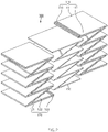
- the electrode assembly 100 comprises a first electrode 110 bent in a zigzag shape, a second electrode 120 bent in a zigzag shape to overlap the first electrode 110, and a separator 130 interposed between the first and second electrodes 110 and 120 and bent in a zigzag shape.
- the first electrode 110 comprises a first collector 111 bent in a zigzag shape and a first electrode active material layer 112 provided on one surface (a surface facing a left direction of the first electrode when viewed in FIG. 2 ) of the first collector 111 facing the second electrode 120.
- the other surface (a surface facing a right direction of the first electrode when viewed in FIG. 2 ) of the first collector 111 is provided as a non-coating surface, on which the first electrode active material layer does not exist.
- the first electrode 110 comprises the first electrode active material layer 112 on the one surface thereof and the non-coating surface, on which the electrode active material layer does not exist, on the other surface thereof.
- the second electrode 120 comprises a second collector 121 bent in a zigzag shape to overlap the first electrode and a second electrode active material layer 122 provided on one surface (a surface facing a left direction of the second electrode when viewed in FIG. 2 ) of the second collector 121 facing the first electrode 110.
- the other surface (a surface facing a left direction of the second electrode when viewed in FIG. 2 ) of the second collector 121 is provided as a non-coating surface, on which the second electrode active material layer does not exist.
- the second electrode 120 comprises the second electrode active material layer 122 on the one surface thereof and the non-coating surface, on which the electrode active material layer does not exist, on the other surface thereof.
- the separator 130 has a zigzag shape to be interposed between the first electrode 110 and the second electrode 120, which overlap each other in a zigzag shape.
- the first electrode 110, the separator 130, and the second electrode 120 may be stacked to overlap each other in a vertical direction to manufacture the electrode assembly 100, thereby improving simplification of the process.
- the secondary battery according to the first embodiment of the present invention improves a bonding structure of the electrode assembly and the cap part, a bonding structure of the electrode assembly and the can, and the structure of the electrode assembly to increase in integration of the electrode assembly accommodated in the can, thereby improving energy density.
- an upper end 110a of the first electrode 110 is disposed at the uppermost end of the electrode assembly 100 to extend longer than the second electrode 120, and a first protrusion piece 113 bonded to the cup part 300 is provided on the upper end 110a of the first electrode 110, which is disposed at the uppermost end of the electrode assembly 100.
- the upper end 110a of the first electrode 110 may be bonded to the cap part 300 through the first protrusion 113 without being deformed in a direction of the cap part 300.
- a space between the electrode assembly 100 and the cap part 300 may be significantly reduced, and the electrode assembly 100 may be additionally secured by the reduced space, thereby improving the energy density.
- the first protrusion piece 113 is provided as one or more embossing part, which protrudes toward the cap part 300, at the upper end of the first collector 111, and the embossing part may be formed by molding the upper end of the first collector 111 to protrude in the direction of the cap part.
- the first protrusion piece 113 may be formed without a separate additional configuration, and as a result, the simplification of the process may increase.
- the upper end 110a of the first electrode 110 provided with the first protrusion piece 113 may be provided as a non-coating surface on which the electrode active material layer does not exist on both surfaces thereof.
- the upper end 110a of the first electrode 110 which is disposed at the uppermost end of the electrode assembly 100, may have a thickness greater than that of the remaining portion of the first electrode 110. Thus, the upper end 110a of the first electrode 110 may be significantly prevented from being bent or folded.
- a lower end 120a of the second electrode 120 is disposed at the lowermost end of the electrode assembly 100 to extend longer than the first electrode 110, and a second protrusion piece 123 bonded to the can 200 is provided on the lower end 120a of the second electrode 120, which is disposed at the lowermost end of the electrode assembly 100.
- the lower end 120a of the second electrode 120 may be bonded to the can 200 through the second protrusion 123 without being deformed in a direction of the can 200.
- a space between the electrode assembly 100 and the can 200 may be significantly reduced, and the electrode assembly 100 may be additionally secured by the reduced space, thereby improving the energy density.
- the second protrusion piece 123 is provided as one or more embossing part, which protrudes toward the can 200, at the lower end of the second collector 121, and the embossing part may be formed by punching the upper end of the second collector 121 to protrude in the direction of the can.
- the second protrusion piece 123 may be formed without a separate additional configuration, and as a result, the simplification of the process may increase.
- the upper end 120a of the second electrode 120 provided with the second protrusion piece 123 may be provided as a non-coating surface on which the electrode active material layer does not exist on both surfaces thereof.
- the lower end 110a of the second electrode 120 which is disposed at the lowermost end of the electrode assembly 100, may have a thickness greater than that of the remaining portion of the second electrode. Thus, the lower end 110a of the second electrode 120 may be significantly prevented from being bent or folded.
- An insulating member 140 having an insulating property may be provided at an end of the first protrusion piece 113 or the second protrusion piece 123, and thus, the short circuit may be previously prevented from occurring by the end of the first protrusion piece 113 or the second protrusion piece 123.
- the insulating member 140 may prevent the end of the first protrusion piece 113 or the second protrusion piece 123 from being damaged, or the insulating member 140 may prevent the first electrode, the separator, and the second electrode from being damaged by the end of the first protrusion piece 113 or the second protrusion piece 123.
- the conductive adhesive member 150 that increases in conductivity may be provided at a portion of the other surface (a right surface when viewed in FIG. 2 ), on which the first collectors 111 overlap each other at the first electrode 110 bent in the zigzag shape.
- the first electrode may be improved in conductivity of the first electrode 110, and the first collectors 111 overlapping each other may be improved in adhesion and bonding through the conductive adhesive member 150.
- the conductive adhesive member 150 that increases in conductivity may be provided at a portion (a left surface when viewed in FIG. 2 ), at which the second collectors 121 overlap each other at the second electrode 120 bent in the zigzag shape.
- the second electrode may be improved in conductivity of the second electrode 120, and the second collectors 121 overlapping each other may be improved in adhesion and bonding through the conductive adhesive member 150.
- the thickness of the conductive adhesive member 150 is less than that of the first collector 111 or the second collector 121. That is, as the thickness of the conductive adhesive member 150 decreases, a degree of integration of the electrode assembly accommodated in the can may increase.
- a protective member 160 having an insulating property may be provided on a bottom surface of the cap part 300 facing the upper end 110a of the first electrode 110, and the upper end 110a of the first electrode 110 and the cap part 300 may be prevented from being in contact with each other through the protective member 160 to prevent the upper end 110a of the first electrode 110 from being damaged.
- a protective member 160 having an insulating property may be provided on a bottom surface of the can 200 facing the lower end 120a of the second electrode 120, and the lower end 120a of the second electrode 120 and the can 200 may be prevented from being in contact with each other through the protective member 160 to prevent the lower end 120a of the second electrode 120 from being damaged.
- the secondary battery according to the first embodiment of the present invention improves the bonding structure of the electrode assembly and the cap part, the bonding structure of the electrode assembly and the can, and the structure of the electrode assembly to increase in integration of the electrode assembly accommodated in the can, thereby improving the energy density.
- a method for manufacturing the secondary battery manufacturing method according to the first embodiment of the present invention comprises a preparation step (S10), a molding step (S20), an assembly step (S30), an accommodation step (S40), and a bonding step (S50).
- the preparation step (S10) comprises a first process of bending a first electrode 110 in a zigzag shape, a second process of bending a second electrode 120 in a zigzag shape to overlap the first electrode 110, and a third process of bending a separator 130, which is interposed between the first electrode 110 and the second electrode 120, in a zigzag shape.
- a first process an upper end 110a of the first electrode 110 is provided to extend longer than the second electrode 120
- a lower end 120a of the second electrode 120 is provided to extend longer than the first electrode 110.
- the first electrode 110 comprises a first collector 111 and a first electrode active material layer 112.
- the first electrode active material layer 112 is provided on only one surface of the first collector 111 facing the second electrode.
- the second electrode 120 comprises a second collector 121 and a second electrode active material layer 122.
- the second electrode active material layer 122 is provided on only the second collector 121 facing the first electrode.
- a first protrusion piece 113 is molded on the upper end 110a of the first electrode 110, and a second protrusion piece 123 is molded on the lower end 120a of the second electrode 120.
- the first protrusion piece 113 is provided as one or more embossing parts for molding a portion of the upper end 110a of the first electrode 110 to protrude to the outside
- the second protrusion piece 123 is provided as one or more embossing parts for molding a portion of the lower end 120a of the second electrode 120 to protrude to the outside.
- an insulating material having an insulating property is applied to ends of the first and second protrusion pieces 113 and 123, and thus, an insulating member 140 is formed on each of the ends of the first and second protrusion pieces 113 and 123.
- the first electrode 110 bent in the zigzag shape, the separator 130 bent in the zigzag shape, and the second electrode 120 bent in the zigzag shape overlap each other to assembly an electrode assembly 100.
- the first protrusion piece 113 formed on the upper end 110a of the first electrode 110 is disposed on the uppermost end of the electrode assembly 100
- the second protrusion piece 123 formed on the lower end of the second electrode 120 is disposed on the lowermost end of the electrode assembly 100.
- the assembly step (S30) further comprises a process of providing a conductive adhesive member 150 for increasing in conductivity at a portion at which the first collectors 111 overlap each other at the first electrode 110, and thus, adhesion, bonding, and conductivity between the first collectors 111 may be improved.
- the assembly step (S30) further comprises a process of providing a conductive adhesive member 150 for increasing in conductivity at a portion at which the second collectors 121 overlap each other at the second electrode 120, and thus, adhesion, bonding, and conductivity between the second collectors 121 may be improved.
- the electrode assembly 100 is accommodated in a can 200.
- the second protrusion piece 123 disposed on the lowermost end of the electrode assembly 100 is bonded to a bottom surface of the can 200.
- the protective member 160 having the insulating properties may be attached to the bottom surface of the can 200 corresponding to the lower end 120a of the second electrode 120 to prevent the lower end of the second electrode 120 and the can 200 from being in contact with each other through the protective member 160, thereby preventing the lower end of the second electrode 120 from being damaged.
- a cap part 300 is bonded to an opening of the can 200.
- the first protrusion piece 113 disposed on the uppermost end of the electrode assembly 100 is bonded to the bottom surface of the cap part 300 to manufacture a finished secondary battery as illustrated in FIG. 4 .
- a protective member 160 having an insulating property may be provided on a bottom surface of the cap part 300 facing the upper end 110a of the first electrode 110, and the upper end 110a of the first electrode 110 and the cap part 300 may be prevented from being in contact with each other through the protective member 160 to prevent the upper end 110a of the first electrode 110 from being damaged.
- a secondary battery according to a second embodiment of the present invention comprises an electrode assembly 100, a can 200 accommodating the electrode assembly 100, and a cap part 300 mounted in an opening of the can 200.
- the electrode assembly 100 comprises a first electrode 110 bent in a zigzag shape, a second electrode 120 bent in a zigzag shape to overlap the first electrode 110, and a separator 113 interposed between the first and second electrodes 111 and 112 and bent in a zigzag shape.
- a first protrusion piece 113 bonded to the cap part 300 is provided on an upper end 110a of the first electrode 110 disposed on the uppermost end of the electrode assembly 100
- a second protrusion piece 123 bonded to the can 200 is provided on a lower end 120a of the second electrode 120 disposed on the lowermost end of the electrode assembly 100.
- the first protrusion piece 113 is provided as a wrinkle part, which is bent in a zigzag shape along a width direction of the can 200 and of which a protruding portion facing the cap part 300 is bonded to the cap part 300, at the upper end of the first collector 111 of the first electrode 110.
- the first protrusion piece 113 is provided as the wrinkle part bent in the zigzag shape, a length of the first protrusion piece 113 may easily increase or decrease, and as a result, the first protrusion piece 113 may be adjusted in length according to a position of the cap part 300 to improve bonding between the first protrusion piece 113 and the cap part 300.
- the second protrusion piece 123 is a wrinkle part, which is bent in a zigzag shape along a width direction of the can 200 and of which a protruding portion facing the cap part 300 is bonded to a bottom surface of the can 200, at the lower end of the second collector 121 of the second electrode 120.
- the second protrusion piece 123 is provided as the wrinkle part bent in the zigzag shape, a length of the second protrusion piece 123 may easily increase or decrease, and as a result, the second protrusion piece 123 may be adjusted in length according to a bonded point of the can 200 to improve bonding between the second protrusion piece 123 and the can 200.
- a method for manufacturing the secondary battery having the above-described structure according to the second embodiment of the present invention comprises a preparation step (S10), a molding step (S20), an assembly step (S30), an accommodation step (S40), and a bonding step (S50).
- the preparation step (S10), the assembly step (S30), the accommodation step (S40), and the bonding step (S50) are the same as those of the method for manufacturing the secondary battery according to the foregoing first embodiment, and thus duplicated descriptions thereof will be omitted.
- a first protrusion piece 113 is molded on an upper end of a first electrode 110, and a second protrusion piece 123 is molded on a lower end 120a of a second electrode 120.
- the first protrusion piece 113 is molded in the form of a wrinkle part by bending the upper end 110a of the first electrode 110 in a zigzag shape along a width direction of a can 200.
- the second protrusion piece 123 is molded in the form of a wrinkle part by bending the lower end 120a of the second electrode 120 in a zigzag shape along the width direction of a can 200.
- an insulating material having an insulating property is applied to ends of the first and second protrusion pieces 113 and 123, and thus, an insulating member 140 is formed on each of the ends of the first and second protrusion pieces 113 and 123.
- each of the first and second protrusion pieces 113 and 123 may be adjusted in length by forming the first and second protrusion pieces 113 and 123 as the wrinkle parts. As a result, the bonding between the electrode assembly 100 and the cap part 300 and between the electrode assembly 100 and the can 200 may be improved.
- a secondary battery according to a third embodiment of the present invention comprises an electrode assembly 100, a can 200 accommodating the electrode assembly 100, and a cap part 300 mounted in an opening of the can 200.
- an upper end 110a of a first electrode 110 which is disposed at the uppermost end of the electrode assembly 100, may have a width less than that of a remaining portion of the first electrode 110.
- the upper end 110a of the first electrode 110 may be significantly prevented from being in contact with an inner wall of a can 200 to prevent short circuit from occurring.
- a lower end 120a of a second electrode 120 which is disposed at the lowermost end of the electrode assembly 100, may have a width less than that of a remaining portion of the second electrode 120.
- the lower end 110a of the second electrode 110 may be prevented from being in contact with the inner wall of the can 200 to prevent the lower end 120a of the second electrode 120 from being damaged.
Landscapes
- Chemical & Material Sciences (AREA)
- Chemical Kinetics & Catalysis (AREA)
- Electrochemistry (AREA)
- General Chemical & Material Sciences (AREA)
- Engineering & Computer Science (AREA)
- Manufacturing & Machinery (AREA)
- Secondary Cells (AREA)
- Sealing Battery Cases Or Jackets (AREA)
Abstract
Description
- The present application claims the benefit of the priority of
Korean Patent Application No. 10-2020-0060586, filed on May 20, 2020 - The present invention relates to a secondary battery, in which energy density and processes are simplified, and a method for manufacturing the same.
- In general, secondary batteries refer to chargeable and dischargeable batteries, unlike primary batteries that are not chargeable. The secondary batteries are being widely used in the high-tech electronic fields such as mobile phones, notebook computers, and camcorders.
- Such a secondary battery is classified into a can type secondary battery in which an electrode assembly is built in a metal can and a pouch type secondary battery in which an electrode assembly is built in a pouch. The can type secondary battery comprises an electrode assembly in which electrodes and separators are alternately stacked, a can accommodating the electrode assembly, and a cap part mounted in an opening of the can. In addition, the pouch type secondary battery comprises an electrode assembly in which electrodes and separators are alternately stacked, a pouch accommodating the electrode assembly, and an electrode lead bonded to an electrode tab provided in the electrode assembly.
- However, the secondary battery has to secure enough space for accommodating the electrode tab and the electrode lead, and thus, there is a problem in that a degree of integration of the electrode assembly accommodated in the can is significantly reduced, and thus, energy density is reduced.
- The present invention is invented to solve the above problems, and an object of the present invention is to improve a structure of an electrode assembly to improve a degree of integration of the electrode assembly, thereby improving energy density and simplification of a process, and a method for manufacturing the same.
- A secondary battery according to the present invention for achieving the above object comprises: an electrode assembly comprising a first electrode bent in a zigzag shape, a second electrode bent in a zigzag shape to overlap the first electrode, and a separator bent in a zigzag shape to be interposed between the first and second electrodes; a can configured to accommodate the electrode assembly; and a cap part mounted in an opening of the can, wherein an upper end of the first electrode is disposed on the uppermost end of the electrode assembly to extend longer than the second electrode, a lower end of the second electrode is disposed on the lowermost end of the electrode assembly to extend longer than the first electrode, a first protrusion piece bonded to the cap part is provided on the upper end of the first electrode, and a second protrusion piece bonded to the can is provided on the lower end of the second electrode.
- The first electrode may comprise a first collector and a first electrode active material layer provided on a surface of the first collector, which faces the second electrode, and the first protrusion piece may be provided as an embossing part, which is bonded to the cap part while protruding toward the cap part, at the upper end of the first collector.
- The first electrode may comprise a first collector and a first electrode active material layer provided on a surface of the first collector, which faces the second electrode, and the first protrusion piece may be provided as a wrinkle part, which is bent in a zigzag shape along a width direction of the can and of which a protruding portion facing the cap part is bonded to the cap part, at an upper end of the first collector.
- A conductive adhesive member for improving conductivity may be provided on a portion of the first electrode, at which the first collectors overlap each other.
- A protective member having an insulating property may be provided on the cap part facing the upper end of the first electrode.
- The second electrode may comprise a second collector and a second electrode active material layer provided on a surface of the second collector, which faces the first electrode, and the second protrusion piece may be provided as an embossing part, which is bonded to the can while protruding toward the can, at the lower end of the second collector.
- The second electrode may comprise a second collector and a second electrode active material layer provided on a surface of the second collector, which faces the first electrode, and the second protrusion piece may be provided as a wrinkle part, which is bent in a zigzag shape along a width direction of the can and of which a protruding portion facing the can is bonded to the can, at a lower end of the second collector.
- A conductive adhesive member for improving conductivity may be provided on a portion of the second electrode, at which the second collectors overlap each other.
- A protective member having an insulating property may be provided on the can facing the lower end of the second electrode.
- An insulating member having an insulating property may be provided on an end of the first protrusion piece or the second protrusion piece.
- The upper end of the first electrode may have a width less than that of a remaining portion of the first electrode.
- The lower end of the second electrode may have a width less than that of a remaining portion of the second electrode.
- A method for manufacturing a secondary battery according to the present invention comprises: a preparation step (S10) comprising a first process of bending a first electrode in a zigzag shape, a second process of bending a second electrode in a zigzag shape to overlap the first electrode, and a third process of bending a separator, which is interposed between the first electrode and the second electrode, in a zigzag shape, wherein an upper end of the first electrode is provided to extend longer than the second electrode, and a lower end of the second electrode is provided to extend longer than the first electrode; a molding step (S20) of molding a first protrusion piece on the upper end of the first electrode and molding a second protrusion piece on the lower end of the second electrode; an assembly step (S30) of allowing the first electrode bent, the separator, and the second electrode, each of which is bent in the zigzag shape, to overlap each other so as to assembly an electrode assembly, wherein the first protrusion piece formed on the upper end of the first electrode is disposed on the uppermost end of the electrode assembly, and the second protrusion piece formed on the lower end of the second electrode is disposed on the lowermost end of the electrode assembly; an accommodation step of accommodating the electrode assembly in a can, wherein the second protrusion piece disposed on the lowermost end of the electrode assembly is bonded to a bottom surface of the can; and a bonding step (S50) of bonding a cap part to an opening of the can, wherein the first protrusion piece disposed on the uppermost end of the electrode assembly is bonded to the cap part.
- The first protrusion piece may be provided as an embossing part protruding toward the cap part or a wrinkle part bent in a zigzag shape along a width direction of the can.
- The second protrusion piece may be provided as an embossing part protruding toward the can or a wrinkle part bent in a zigzag shape along a width direction of the can.
- The secondary battery according to the present invention may comprise the electrode assembly, the can, and the cap part, and the electrode assembly may comprise the first electrode, the separator, and the second electrode, which are stacked to overlap each other in the zigzag shape. The first electrode may comprise the first protrusion piece bonded to the cap part, and the second electrode may comprise the second protrusion piece bonded to the can. Due to the above-described characteristics, the spaces between the electrode assembly and the cap part and between the electrode assembly and the can may be minimized to improve the degree of integration of the electrode assembly. As a result, there is no need for the energy density and the electrode tab and electrode lead to significantly simplify the process.
- In addition, in the secondary battery according to the present invention, the first protrusion piece of the first electrode may be provided as the embossing part or the wrinkle part bonded to the cap part. Due to the above-described characteristic, the first protrusion piece and the cap part may be easily bonded to each other.
- In addition, in the secondary battery according to the present invention, the first electrode may comprise the first collector and the first electrode active material layer, and the conductive adhesive member for improving the conductivity may be comprised at the portion at which the first collectors overlap each other. Due to the above-described characteristic, the bonding property and conductivity between the first collectors overlapping each other may be improved.
- In addition, in the secondary battery according to the present invention, the protective member having the insulating property may be provided on the cap part facing the upper end of the first electrode. Due to the above-described characteristic, the cap part and the first electrode may be prevented from being in contact with each other to prevent the first electrode from being damaged.
- In addition, in the secondary battery according to the present invention, the second protrusion piece of the second electrode may be formed as the embossing part or the wrinkle part. Due to the above-described characteristic, the second protrusion piece and the can may be easily bonded to each other.
- In addition, in the secondary battery according to the present invention, the insulating member comprising the insulating property may be provided at the end of each of the first and second protrusion pieces. Due to the above-described characteristic, the electrode assembly may be provided from being damaged by the ends of the first and second protrusion pieces, and the short circuit may be prevented from occurring by the ends of the first and second protrusion pieces.
-
-
FIG. 1 is a cross-sectional view of a secondary battery according to a first embodiment of the present invention. -
FIG. 2 is a perspective view illustrating an electrode assembly of the secondary battery according to the first embodiment of the present invention. -
FIG. 3 is a side view ofFIG. 2 . -
FIG. 4 is a cross-sectional view of the secondary battery comprising an adhesive member according to the first embodiment of the present invention. -
FIG. 5 is a flowchart illustrating a method for manufacturing the secondary battery according to the first embodiment of the present invention. -
FIG. 6 is a side view illustrating a preparation step of the method for manufacturing the secondary battery according to the first embodiment of the present invention. -
FIG. 7 is a side view illustrating a molding step of the method for manufacturing the secondary battery according to the first embodiment of the present invention. -
FIG. 8 is a cross-sectional view illustrating an assembly step and an accommodation step of the method for manufacturing the secondary battery according to the first embodiment of the present invention. -
FIG. 9 is a cross-sectional view of a secondary battery according to a second embodiment of the present invention. -
FIG. 10 is a perspective view illustrating an electrode assembly of the secondary battery according to the second embodiment of the present invention. -
FIG. 11 is a side view ofFIG. 10 . -
FIG. 12 is a perspective view of a secondary battery according to a third embodiment of the present invention. - Hereinafter, embodiments of the present invention will be described in detail with reference to the accompanying drawings in such a manner that the technical idea of the present invention may easily be carried out by a person with ordinary skill in the art to which the invention pertains. The present invention may, however, be embodied in different forms and should not be construed as limited to the embodiments set forth herein. In the drawings, anything unnecessary for describing the present invention will be omitted for clarity, and also like reference numerals in the drawings denote like elements.
- As illustrated in
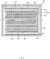
FIGS. 1 to 4 , a secondary battery according to a first embodiment of the present invention comprises anelectrode assembly 100, acan 200 accommodating theelectrode assembly 100, and acap part 300 mounted in an opening of thecan 200. - Here, the
electrode assembly 100 comprises afirst electrode 110 bent in a zigzag shape, asecond electrode 120 bent in a zigzag shape to overlap thefirst electrode 110, and aseparator 130 interposed between the first andsecond electrodes - The
first electrode 110 comprises afirst collector 111 bent in a zigzag shape and a first electrodeactive material layer 112 provided on one surface (a surface facing a left direction of the first electrode when viewed inFIG. 2 ) of thefirst collector 111 facing thesecond electrode 120. The other surface (a surface facing a right direction of the first electrode when viewed inFIG. 2 ) of thefirst collector 111 is provided as a non-coating surface, on which the first electrode active material layer does not exist. - That is, the
first electrode 110 comprises the first electrodeactive material layer 112 on the one surface thereof and the non-coating surface, on which the electrode active material layer does not exist, on the other surface thereof. - The
second electrode 120 comprises asecond collector 121 bent in a zigzag shape to overlap the first electrode and a second electrodeactive material layer 122 provided on one surface (a surface facing a left direction of the second electrode when viewed inFIG. 2 ) of thesecond collector 121 facing thefirst electrode 110. The other surface (a surface facing a left direction of the second electrode when viewed inFIG. 2 ) of thesecond collector 121 is provided as a non-coating surface, on which the second electrode active material layer does not exist. - That is, the
second electrode 120 comprises the second electrodeactive material layer 122 on the one surface thereof and the non-coating surface, on which the electrode active material layer does not exist, on the other surface thereof. - The
separator 130 has a zigzag shape to be interposed between thefirst electrode 110 and thesecond electrode 120, which overlap each other in a zigzag shape. - In the secondary battery having the above-described structure according to the first embodiment of the present invention, the
first electrode 110, theseparator 130, and thesecond electrode 120 may be stacked to overlap each other in a vertical direction to manufacture theelectrode assembly 100, thereby improving simplification of the process. - The secondary battery according to the first embodiment of the present invention improves a bonding structure of the electrode assembly and the cap part, a bonding structure of the electrode assembly and the can, and the structure of the electrode assembly to increase in integration of the electrode assembly accommodated in the can, thereby improving energy density.
- As a first example, in the secondary battery according to the first embodiment of the present invention, an
upper end 110a of thefirst electrode 110 is disposed at the uppermost end of theelectrode assembly 100 to extend longer than thesecond electrode 120, and afirst protrusion piece 113 bonded to thecup part 300 is provided on theupper end 110a of thefirst electrode 110, which is disposed at the uppermost end of theelectrode assembly 100. - That is, in the secondary battery according to the first embodiment of the present invention, the
upper end 110a of thefirst electrode 110 may be bonded to thecap part 300 through thefirst protrusion 113 without being deformed in a direction of thecap part 300. Thus, a space between theelectrode assembly 100 and thecap part 300 may be significantly reduced, and theelectrode assembly 100 may be additionally secured by the reduced space, thereby improving the energy density. - The
first protrusion piece 113 is provided as one or more embossing part, which protrudes toward thecap part 300, at the upper end of thefirst collector 111, and the embossing part may be formed by molding the upper end of thefirst collector 111 to protrude in the direction of the cap part. Thus, thefirst protrusion piece 113 may be formed without a separate additional configuration, and as a result, the simplification of the process may increase. - Here, the
upper end 110a of thefirst electrode 110 provided with thefirst protrusion piece 113 may be provided as a non-coating surface on which the electrode active material layer does not exist on both surfaces thereof. - The
upper end 110a of thefirst electrode 110, which is disposed at the uppermost end of theelectrode assembly 100, may have a thickness greater than that of the remaining portion of thefirst electrode 110. Thus, theupper end 110a of thefirst electrode 110 may be significantly prevented from being bent or folded. - As a second example, in the secondary battery according to the first embodiment of the present invention, a
lower end 120a of thesecond electrode 120 is disposed at the lowermost end of theelectrode assembly 100 to extend longer than thefirst electrode 110, and asecond protrusion piece 123 bonded to thecan 200 is provided on thelower end 120a of thesecond electrode 120, which is disposed at the lowermost end of theelectrode assembly 100. - That is, in the secondary battery according to the first embodiment of the present invention, the
lower end 120a of thesecond electrode 120 may be bonded to thecan 200 through thesecond protrusion 123 without being deformed in a direction of thecan 200. Thus, a space between theelectrode assembly 100 and thecan 200 may be significantly reduced, and theelectrode assembly 100 may be additionally secured by the reduced space, thereby improving the energy density. - The
second protrusion piece 123 is provided as one or more embossing part, which protrudes toward thecan 200, at the lower end of thesecond collector 121, and the embossing part may be formed by punching the upper end of thesecond collector 121 to protrude in the direction of the can. Thus, thesecond protrusion piece 123 may be formed without a separate additional configuration, and as a result, the simplification of the process may increase. - Here, the
upper end 120a of thesecond electrode 120 provided with thesecond protrusion piece 123 may be provided as a non-coating surface on which the electrode active material layer does not exist on both surfaces thereof. - The
lower end 110a of thesecond electrode 120, which is disposed at the lowermost end of theelectrode assembly 100, may have a thickness greater than that of the remaining portion of the second electrode. Thus, thelower end 110a of thesecond electrode 120 may be significantly prevented from being bent or folded. - An insulating
member 140 having an insulating property may be provided at an end of thefirst protrusion piece 113 or thesecond protrusion piece 123, and thus, the short circuit may be previously prevented from occurring by the end of thefirst protrusion piece 113 or thesecond protrusion piece 123. Particularly, the insulatingmember 140 may prevent the end of thefirst protrusion piece 113 or thesecond protrusion piece 123 from being damaged, or the insulatingmember 140 may prevent the first electrode, the separator, and the second electrode from being damaged by the end of thefirst protrusion piece 113 or thesecond protrusion piece 123. - As a third example, in the secondary battery according to the first embodiment of the present invention, the conductive
adhesive member 150 that increases in conductivity may be provided at a portion of the other surface (a right surface when viewed inFIG. 2 ), on which thefirst collectors 111 overlap each other at thefirst electrode 110 bent in the zigzag shape. Thus, the first electrode may be improved in conductivity of thefirst electrode 110, and thefirst collectors 111 overlapping each other may be improved in adhesion and bonding through the conductiveadhesive member 150. - The conductive
adhesive member 150 that increases in conductivity may be provided at a portion (a left surface when viewed inFIG. 2 ), at which thesecond collectors 121 overlap each other at thesecond electrode 120 bent in the zigzag shape. Thus, the second electrode may be improved in conductivity of thesecond electrode 120, and thesecond collectors 121 overlapping each other may be improved in adhesion and bonding through the conductiveadhesive member 150. - Here, the thickness of the conductive
adhesive member 150 is less than that of thefirst collector 111 or thesecond collector 121. That is, as the thickness of the conductiveadhesive member 150 decreases, a degree of integration of the electrode assembly accommodated in the can may increase. - A
protective member 160 having an insulating property may be provided on a bottom surface of thecap part 300 facing theupper end 110a of thefirst electrode 110, and theupper end 110a of thefirst electrode 110 and thecap part 300 may be prevented from being in contact with each other through theprotective member 160 to prevent theupper end 110a of thefirst electrode 110 from being damaged. - A
protective member 160 having an insulating property may be provided on a bottom surface of thecan 200 facing thelower end 120a of thesecond electrode 120, and thelower end 120a of thesecond electrode 120 and thecan 200 may be prevented from being in contact with each other through theprotective member 160 to prevent thelower end 120a of thesecond electrode 120 from being damaged. - Thus, the secondary battery according to the first embodiment of the present invention improves the bonding structure of the electrode assembly and the cap part, the bonding structure of the electrode assembly and the can, and the structure of the electrode assembly to increase in integration of the electrode assembly accommodated in the can, thereby improving the energy density.
- Hereinafter, a method for manufacturing the secondary battery according to the first embodiment of the present invention will be described.
- As illustrated in
FIGS. 5 to 8 , a method for manufacturing the secondary battery manufacturing method according to the first embodiment of the present invention comprises a preparation step (S10), a molding step (S20), an assembly step (S30), an accommodation step (S40), and a bonding step (S50). - The preparation step (S10) comprises a first process of bending a
first electrode 110 in a zigzag shape, a second process of bending asecond electrode 120 in a zigzag shape to overlap thefirst electrode 110, and a third process of bending aseparator 130, which is interposed between thefirst electrode 110 and thesecond electrode 120, in a zigzag shape. Here, in the first process, anupper end 110a of thefirst electrode 110 is provided to extend longer than thesecond electrode 120, and in the second process, alower end 120a of thesecond electrode 120 is provided to extend longer than thefirst electrode 110. - Here, the
first electrode 110 comprises afirst collector 111 and a first electrodeactive material layer 112. The first electrodeactive material layer 112 is provided on only one surface of thefirst collector 111 facing the second electrode. Also, thesecond electrode 120 comprises asecond collector 121 and a second electrodeactive material layer 122. The second electrodeactive material layer 122 is provided on only thesecond collector 121 facing the first electrode. - In the molding step (S20), a
first protrusion piece 113 is molded on theupper end 110a of thefirst electrode 110, and asecond protrusion piece 123 is molded on thelower end 120a of thesecond electrode 120. Here, thefirst protrusion piece 113 is provided as one or more embossing parts for molding a portion of theupper end 110a of thefirst electrode 110 to protrude to the outside, and thesecond protrusion piece 123 is provided as one or more embossing parts for molding a portion of thelower end 120a of thesecond electrode 120 to protrude to the outside. - In the molding step (S20), an insulating material having an insulating property is applied to ends of the first and
second protrusion pieces member 140 is formed on each of the ends of the first andsecond protrusion pieces - In the assembly step (S30), the
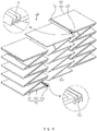
first electrode 110 bent in the zigzag shape, theseparator 130 bent in the zigzag shape, and thesecond electrode 120 bent in the zigzag shape overlap each other to assembly anelectrode assembly 100. Here, thefirst protrusion piece 113 formed on theupper end 110a of thefirst electrode 110 is disposed on the uppermost end of theelectrode assembly 100, and thesecond protrusion piece 123 formed on the lower end of thesecond electrode 120 is disposed on the lowermost end of theelectrode assembly 100. - The assembly step (S30) further comprises a process of providing a conductive
adhesive member 150 for increasing in conductivity at a portion at which thefirst collectors 111 overlap each other at thefirst electrode 110, and thus, adhesion, bonding, and conductivity between thefirst collectors 111 may be improved. In addition, the assembly step (S30) further comprises a process of providing a conductiveadhesive member 150 for increasing in conductivity at a portion at which thesecond collectors 121 overlap each other at thesecond electrode 120, and thus, adhesion, bonding, and conductivity between thesecond collectors 121 may be improved. - In the accommodation step (S40), the
electrode assembly 100 is accommodated in acan 200. Here, thesecond protrusion piece 123 disposed on the lowermost end of theelectrode assembly 100 is bonded to a bottom surface of thecan 200. - In the accommodation step (S40), before accommodating the electrode assembly in the can, the
protective member 160 having the insulating properties may be attached to the bottom surface of thecan 200 corresponding to thelower end 120a of thesecond electrode 120 to prevent the lower end of thesecond electrode 120 and thecan 200 from being in contact with each other through theprotective member 160, thereby preventing the lower end of thesecond electrode 120 from being damaged. - In the bonding step (S50), a
cap part 300 is bonded to an opening of thecan 200. Here, thefirst protrusion piece 113 disposed on the uppermost end of theelectrode assembly 100 is bonded to the bottom surface of thecap part 300 to manufacture a finished secondary battery as illustrated inFIG. 4 . - In the bonding step (S50), a
protective member 160 having an insulating property may be provided on a bottom surface of thecap part 300 facing theupper end 110a of thefirst electrode 110, and theupper end 110a of thefirst electrode 110 and thecap part 300 may be prevented from being in contact with each other through theprotective member 160 to prevent theupper end 110a of thefirst electrode 110 from being damaged. - Hereinafter, in descriptions of another embodiment of the present invention, constituents having the same function as the above-mentioned embodiment have been given the same reference numeral in the drawings, and thus duplicated description will be omitted.
- As illustrated in
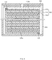
FIGS. 9 to 11 , a secondary battery according to a second embodiment of the present invention comprises anelectrode assembly 100, a can 200 accommodating theelectrode assembly 100, and acap part 300 mounted in an opening of thecan 200. - The
electrode assembly 100 comprises afirst electrode 110 bent in a zigzag shape, asecond electrode 120 bent in a zigzag shape to overlap thefirst electrode 110, and aseparator 113 interposed between the first andsecond electrodes - Also, a
first protrusion piece 113 bonded to thecap part 300 is provided on anupper end 110a of thefirst electrode 110 disposed on the uppermost end of theelectrode assembly 100, and asecond protrusion piece 123 bonded to thecan 200 is provided on alower end 120a of thesecond electrode 120 disposed on the lowermost end of theelectrode assembly 100. - Here, the
first protrusion piece 113 is provided as a wrinkle part, which is bent in a zigzag shape along a width direction of thecan 200 and of which a protruding portion facing thecap part 300 is bonded to thecap part 300, at the upper end of thefirst collector 111 of thefirst electrode 110. - That is, since the
first protrusion piece 113 is provided as the wrinkle part bent in the zigzag shape, a length of thefirst protrusion piece 113 may easily increase or decrease, and as a result, thefirst protrusion piece 113 may be adjusted in length according to a position of thecap part 300 to improve bonding between thefirst protrusion piece 113 and thecap part 300. - In addition, the
second protrusion piece 123 is a wrinkle part, which is bent in a zigzag shape along a width direction of thecan 200 and of which a protruding portion facing thecap part 300 is bonded to a bottom surface of thecan 200, at the lower end of thesecond collector 121 of thesecond electrode 120. - That is, since the
second protrusion piece 123 is provided as the wrinkle part bent in the zigzag shape, a length of thesecond protrusion piece 123 may easily increase or decrease, and as a result, thesecond protrusion piece 123 may be adjusted in length according to a bonded point of thecan 200 to improve bonding between thesecond protrusion piece 123 and thecan 200. - A method for manufacturing the secondary battery having the above-described structure according to the second embodiment of the present invention comprises a preparation step (S10), a molding step (S20), an assembly step (S30), an accommodation step (S40), and a bonding step (S50). Here, the preparation step (S10), the assembly step (S30), the accommodation step (S40), and the bonding step (S50) are the same as those of the method for manufacturing the secondary battery according to the foregoing first embodiment, and thus duplicated descriptions thereof will be omitted.
- In the molding step (S20), a
first protrusion piece 113 is molded on an upper end of afirst electrode 110, and asecond protrusion piece 123 is molded on alower end 120a of asecond electrode 120. Here, thefirst protrusion piece 113 is molded in the form of a wrinkle part by bending theupper end 110a of thefirst electrode 110 in a zigzag shape along a width direction of acan 200. In addition, thesecond protrusion piece 123 is molded in the form of a wrinkle part by bending thelower end 120a of thesecond electrode 120 in a zigzag shape along the width direction of acan 200. - Here, an insulating material having an insulating property is applied to ends of the first and
second protrusion pieces member 140 is formed on each of the ends of the first andsecond protrusion pieces - In the method for manufacturing the secondary battery according to the second embodiment of the present invention, each of the first and
second protrusion pieces second protrusion pieces electrode assembly 100 and thecap part 300 and between theelectrode assembly 100 and thecan 200 may be improved. - As illustrated in
FIGS. 12 , a secondary battery according to a third embodiment of the present invention comprises anelectrode assembly 100, a can 200 accommodating theelectrode assembly 100, and acap part 300 mounted in an opening of thecan 200. - Here, an
upper end 110a of afirst electrode 110, which is disposed at the uppermost end of theelectrode assembly 100, may have a width less than that of a remaining portion of thefirst electrode 110. Thus, theupper end 110a of thefirst electrode 110 may be significantly prevented from being in contact with an inner wall of acan 200 to prevent short circuit from occurring. - In addition, a
lower end 120a of asecond electrode 120, which is disposed at the lowermost end of theelectrode assembly 100, may have a width less than that of a remaining portion of thesecond electrode 120. Thus, thelower end 110a of thesecond electrode 110 may be prevented from being in contact with the inner wall of thecan 200 to prevent thelower end 120a of thesecond electrode 120 from being damaged. - Accordingly, the scope of the present invention is defined by the appended claims more than the foregoing description and the exemplary embodiments described therein. Various modifications made within the meaning of an equivalent of the claims of the invention and within the claims are to be regarded to be in the scope of the present invention.
-
- 100:
- Electrode assembly
- 110:
- First electrode
- 111:
- First collector
- 112:
- First electrode active material layer
- 113:
- First protrusion piece
- 120:
- Second electrode
- 121:
- Second collector
- 122:
- Second electrode active material layer
- 123:
- Second protrusion piece
- 130:
- Separator
Claims (15)
- A secondary battery comprising:an electrode assembly comprising a first electrode bent in a zigzag shape, a second electrode bent in a zigzag shape to overlap the first electrode, and a separator bent in a zigzag shape to be interposed between the first and second electrodes;a can configured to accommodate the electrode assembly; anda cap part mounted in an opening of the can,wherein an upper end of the first electrode is disposed on the uppermost end of the electrode assembly to extend longer than the second electrode,a lower end of the second electrode is disposed on the lowermost end of the electrode assembly to extend longer than the first electrode,a first protrusion piece bonded to the cap part is provided on the upper end of the first electrode, anda second protrusion piece bonded to the can is provided on the lower end of the second electrode.
- The secondary battery of claim 1, wherein the first electrode comprises a first collector and a first electrode active material layer provided on a surface of the first collector, which faces the second electrode, and
the first protrusion piece is provided as an embossing part, which is bonded to the cap part while protruding toward the cap part, at the upper end of the first collector. - The secondary battery of claim 1, wherein the first electrode comprises a first collector and a first electrode active material layer provided on a surface of the first collector, which faces the second electrode, and
the first protrusion piece is provided as a wrinkle part, which is bent in a zigzag shape along a width direction of the can and of which a protruding portion facing the cap part is bonded to the cap part, at an upper end of the first collector. - The secondary battery of claim 2 or 3, wherein a conductive adhesive member for improving conductivity is provided on a portion of the first electrode, at which the first collectors overlap each other.
- The secondary battery of claim 1, wherein a protective member having an insulating property is provided on the cap part facing the upper end of the first electrode.
- The secondary battery of claim 1, wherein the second electrode comprises a second collector and a second electrode active material layer provided on a surface of the second collector, which faces the first electrode, and
the second protrusion piece is provided as an embossing part, which is bonded to the can while protruding toward the can, at the lower end of the second collector. - The secondary battery of claim 1, wherein the second electrode comprises a second collector and a second electrode active material layer provided on a surface of the second collector, which faces the first electrode, and
the second protrusion piece is provided as a wrinkle part, which is bent in a zigzag shape along a width direction of the can and of which a protruding portion facing the can is bonded to the can, at a lower end of the second collector. - The secondary battery of claim 6 or 7, wherein a conductive adhesive member for improving conductivity is provided on a portion of the second electrode, at which the second collectors overlap each other.
- The secondary battery of claim 1, wherein a protective member having an insulating property is provided on the can facing the lower end of the second electrode.
- The secondary battery of claim 1, wherein an insulating member having an insulating property is provided on an end of the first protrusion piece or the second protrusion piece.
- The secondary battery of claim 1, wherein the upper end of the first electrode has a width less than that of a remaining portion of the first electrode.
- The secondary battery of claim 1, wherein the lower end of the second electrode has a width less than that of a remaining portion of the second electrode.
- A method for manufacturing a secondary battery, the method comprising:a preparation step (S10) comprising a first process of bending a first electrode in a zigzag shape, a second process of bending a second electrode in a zigzag shape to overlap the first electrode, and a third process of bending a separator, which is interposed between the first electrode and the second electrode, in a zigzag shape, wherein an upper end of the first electrode is provided to extend longer than the second electrode, and a lower end of the second electrode is provided to extend longer than the first electrode;a molding step (S20) of molding a first protrusion piece on the upper end of the first electrode and molding a second protrusion piece on the lower end of the second electrode;an assembly step (S30) of allowing the first electrode bent, the separator, and the second electrode, each of which is bent in the zigzag shape, to overlap each other so as to assembly an electrode assembly, wherein the first protrusion piece formed on the upper end of the first electrode is disposed on the uppermost end of the electrode assembly, and the second protrusion piece formed on the lower end of the second electrode is disposed on the lowermost end of the electrode assembly;an accommodation step of accommodating the electrode assembly in a can, wherein the second protrusion piece disposed on the lowermost end of the electrode assembly is bonded to a bottom surface of the can; anda bonding step (S50) of bonding a cap part to an opening of the can, wherein the first protrusion piece disposed on the uppermost end of the electrode assembly is bonded to the cap part.
- The method of claim 13, wherein the first protrusion piece is provided as an embossing part protruding toward the cap part or a wrinkle part bent in a zigzag shape along a width direction of the can.
- The method of claim 14, wherein the second protrusion piece is provided as an embossing part protruding toward the can or a wrinkle part bent in a zigzag shape along a width direction of the can.
Applications Claiming Priority (2)
| Application Number | Priority Date | Filing Date | Title |
|---|---|---|---|
| KR1020200060586A KR102782785B1 (en) | 2020-05-20 | 2020-05-20 | Secondary battery and manufacturing method for the same |
| PCT/KR2021/005388 WO2021235724A1 (en) | 2020-05-20 | 2021-04-28 | Secondary battery and method for manufacturing same |
Publications (2)
| Publication Number | Publication Date |
|---|---|
| EP4040591A1 true EP4040591A1 (en) | 2022-08-10 |
| EP4040591A4 EP4040591A4 (en) | 2024-02-14 |
Family
ID=78698085
Family Applications (1)
| Application Number | Title | Priority Date | Filing Date |
|---|---|---|---|
| EP21808512.4A Pending EP4040591A4 (en) | 2020-05-20 | 2021-04-28 | RECHARGEABLE BATTERY AND ASSOCIATED MANUFACTURING METHOD |
Country Status (5)
| Country | Link |
|---|---|
| US (1) | US20220393223A1 (en) |
| EP (1) | EP4040591A4 (en) |
| KR (1) | KR102782785B1 (en) |
| CN (1) | CN114556687B (en) |
| WO (1) | WO2021235724A1 (en) |
Families Citing this family (1)
| Publication number | Priority date | Publication date | Assignee | Title |
|---|---|---|---|---|
| JP7354971B2 (en) | 2020-09-11 | 2023-10-03 | トヨタ自動車株式会社 | battery module |
Family Cites Families (21)
| Publication number | Priority date | Publication date | Assignee | Title |
|---|---|---|---|---|
| CN1277330C (en) * | 1999-08-10 | 2006-09-27 | 三洋电机株式会社 | Non-aqueous electrolyte secondary battery and its mfg. method |
| KR100319109B1 (en) * | 1999-11-25 | 2002-01-09 | 김순택 | Electrode of secondary battery and method for making the same |
| JP3825622B2 (en) * | 2000-11-20 | 2006-09-27 | 三洋電機株式会社 | Secondary battery |
| KR200262458Y1 (en) * | 2001-08-29 | 2002-03-25 | 구성회 | Secondary battery |
| JP4019722B2 (en) * | 2002-01-29 | 2007-12-12 | 松下電器産業株式会社 | Coin-cell battery |
| KR100907623B1 (en) * | 2006-05-15 | 2009-07-15 | 주식회사 엘지화학 | Novel laminated electrode assembly for secondary battery |
| KR101329876B1 (en) * | 2006-07-18 | 2013-11-15 | 삼성에스디아이 주식회사 | Rechargeable battery comprising electrode tab with elasticity |
| KR101142589B1 (en) * | 2006-11-15 | 2012-05-10 | 파나소닉 주식회사 | Collector for nonaqueous secondary battery, and nonaqueous secondary battery electrode plate and nonaqueous secondary battery using the collector |
| TWM352782U (en) * | 2008-07-04 | 2009-03-11 | Exa Energy Technology Co Ltd | Foldable type secondary cell |
| US9153813B2 (en) * | 2008-12-31 | 2015-10-06 | Samsung Sdi Co., Ltd. | Secondary battery |
| JP2010205469A (en) * | 2009-03-02 | 2010-09-16 | Sanyo Electric Co Ltd | Method of manufacturing sealed battery, and sealed battery |
| KR101023103B1 (en) * | 2009-03-11 | 2011-03-24 | 에스비리모티브 주식회사 | Secondary battery |
| KR101075289B1 (en) * | 2009-06-08 | 2011-10-19 | 삼성에스디아이 주식회사 | Cylindrical lithium ion secondary battery |
| KR20130132230A (en) * | 2012-05-25 | 2013-12-04 | 주식회사 엘지화학 | A stepwise electrode assembly, and battery cell, battery pack and device comprising the same |
| CN104103854B (en) * | 2014-06-12 | 2016-07-06 | 河北工业大学 | A kind of stacked column lithium ion battery and preparation method thereof |
| KR102284572B1 (en) * | 2014-10-07 | 2021-08-03 | 삼성에스디아이 주식회사 | Rechargeable battery |
| JP2016129095A (en) * | 2015-01-09 | 2016-07-14 | シチズンホールディングス株式会社 | Flat type battery |
| KR101853166B1 (en) * | 2015-04-15 | 2018-04-30 | 주식회사 엘지화학 | Secondary battery, component for secondary battery and method for fabricating the same |
| KR20170050444A (en) * | 2015-10-30 | 2017-05-11 | 주식회사 엘지화학 | Pouch type secondary battery |
| JP6605996B2 (en) * | 2016-03-17 | 2019-11-13 | 株式会社東芝 | Batteries, battery packs, and vehicles |
| US10833370B2 (en) * | 2017-06-15 | 2020-11-10 | Panasonic Intellectual Property Management Co., Ltd. | Battery and battery manufacturing method |
-
2020
- 2020-05-20 KR KR1020200060586A patent/KR102782785B1/en active Active
-
2021
- 2021-04-28 EP EP21808512.4A patent/EP4040591A4/en active Pending
- 2021-04-28 CN CN202180005992.5A patent/CN114556687B/en active Active
- 2021-04-28 US US17/774,631 patent/US20220393223A1/en active Pending
- 2021-04-28 WO PCT/KR2021/005388 patent/WO2021235724A1/en not_active Ceased
Also Published As
| Publication number | Publication date |
|---|---|
| CN114556687A (en) | 2022-05-27 |
| KR102782785B1 (en) | 2025-03-18 |
| WO2021235724A1 (en) | 2021-11-25 |
| KR20210143595A (en) | 2021-11-29 |
| CN114556687B (en) | 2024-06-04 |
| EP4040591A4 (en) | 2024-02-14 |
| US20220393223A1 (en) | 2022-12-08 |
Similar Documents
| Publication | Publication Date | Title |
|---|---|---|
| US12243975B2 (en) | Method for manufacturing secondary battery and pouch for secondary battery | |
| JP4243409B2 (en) | Lithium secondary battery | |
| EP2309582A2 (en) | Rechargeable battery and method of manufacturing same | |
| US20180083255A1 (en) | Rechargeable battery | |
| US20080160398A1 (en) | Secondary battery | |
| US8986868B2 (en) | Rechargeable battery | |
| US9991500B2 (en) | Rechargeable battery | |
| US20250007134A1 (en) | Battery Cell with Chamfered Protective Tape | |
| KR100876266B1 (en) | Secondary battery | |
| US11329338B2 (en) | Rechargeable battery | |
| EP4040591A1 (en) | Secondary battery and method for manufacturing same | |
| KR20170087747A (en) | Electrode Assembly and Secondary battery with the Same and Method of thereof | |
| CN114902474A (en) | Rechargeable battery | |
| EP4002561A2 (en) | Rechargeable battery | |
| US20110318620A1 (en) | Rechargeable battery | |
| JP3864041B2 (en) | battery | |
| US20250364702A1 (en) | Secondary battery | |
| US20260081310A1 (en) | Electrode assembly and secondary battery including same | |
| US20260081272A1 (en) | Secondary battery and method of manufacturing same | |
| US20260038972A1 (en) | Secondary battery and method of manufacturing same | |
| KR20240041752A (en) | Electrode, preparation method thereof and electrode assembly | |
| US20250316745A1 (en) | Secondary battery | |
| US20250385356A1 (en) | Secondary battery | |
| KR100382067B1 (en) | Lithium secondary battery and the fabrication method thereof | |
| US20260066500A1 (en) | Secondary battery and method of manufacturing the same |
Legal Events
| Date | Code | Title | Description |
|---|---|---|---|
| STAA | Information on the status of an ep patent application or granted ep patent |
Free format text: STATUS: THE INTERNATIONAL PUBLICATION HAS BEEN MADE |
|
| PUAI | Public reference made under article 153(3) epc to a published international application that has entered the european phase |
Free format text: ORIGINAL CODE: 0009012 |
|
| STAA | Information on the status of an ep patent application or granted ep patent |
Free format text: STATUS: REQUEST FOR EXAMINATION WAS MADE |
|
| 17P | Request for examination filed |
Effective date: 20220505 |
|
| AK | Designated contracting states |
Kind code of ref document: A1 Designated state(s): AL AT BE BG CH CY CZ DE DK EE ES FI FR GB GR HR HU IE IS IT LI LT LU LV MC MK MT NL NO PL PT RO RS SE SI SK SM TR |
|
| DAV | Request for validation of the european patent (deleted) | ||
| DAX | Request for extension of the european patent (deleted) | ||
| A4 | Supplementary search report drawn up and despatched |
Effective date: 20240111 |
|
| RIC1 | Information provided on ipc code assigned before grant |
Ipc: H01M 50/531 20210101ALI20240105BHEP Ipc: H01M 50/15 20210101ALI20240105BHEP Ipc: H01M 50/148 20210101ALI20240105BHEP Ipc: H01M 50/116 20210101ALI20240105BHEP Ipc: H01M 10/04 20060101ALI20240105BHEP Ipc: H01M 50/172 20210101ALI20240105BHEP Ipc: H01M 50/528 20210101AFI20240105BHEP |