EP4040579B1 - Method of manufacturing pouch-shaped battery cell using protective film and pouch-shaped battery cell manufactured using the same - Google Patents
Method of manufacturing pouch-shaped battery cell using protective film and pouch-shaped battery cell manufactured using the same Download PDFInfo
- Publication number
- EP4040579B1 EP4040579B1 EP20898352.8A EP20898352A EP4040579B1 EP 4040579 B1 EP4040579 B1 EP 4040579B1 EP 20898352 A EP20898352 A EP 20898352A EP 4040579 B1 EP4040579 B1 EP 4040579B1
- Authority
- EP
- European Patent Office
- Prior art keywords
- electrode assembly
- protective film
- receiving portion
- assembly receiving
- outer periphery
- Prior art date
- Legal status (The legal status is an assumption and is not a legal conclusion. Google has not performed a legal analysis and makes no representation as to the accuracy of the status listed.)
- Active
Links
Images



Classifications
-
- C—CHEMISTRY; METALLURGY
- C09—DYES; PAINTS; POLISHES; NATURAL RESINS; ADHESIVES; COMPOSITIONS NOT OTHERWISE PROVIDED FOR; APPLICATIONS OF MATERIALS NOT OTHERWISE PROVIDED FOR
- C09J—ADHESIVES; NON-MECHANICAL ASPECTS OF ADHESIVE PROCESSES IN GENERAL; ADHESIVE PROCESSES NOT PROVIDED FOR ELSEWHERE; USE OF MATERIALS AS ADHESIVES
- C09J5/00—Adhesive processes in general; Adhesive processes not provided for elsewhere, e.g. relating to primers
-
- H—ELECTRICITY
- H01—ELECTRIC ELEMENTS
- H01M—PROCESSES OR MEANS, e.g. BATTERIES, FOR THE DIRECT CONVERSION OF CHEMICAL ENERGY INTO ELECTRICAL ENERGY
- H01M10/00—Secondary cells; Manufacture thereof
- H01M10/04—Construction or manufacture in general
- H01M10/049—Processes for forming or storing electrodes in the battery container
-
- H—ELECTRICITY
- H01—ELECTRIC ELEMENTS
- H01M—PROCESSES OR MEANS, e.g. BATTERIES, FOR THE DIRECT CONVERSION OF CHEMICAL ENERGY INTO ELECTRICAL ENERGY
- H01M10/00—Secondary cells; Manufacture thereof
- H01M10/42—Methods or arrangements for servicing or maintenance of secondary cells or secondary half-cells
- H01M10/44—Methods for charging or discharging
- H01M10/446—Initial charging measures
-
- H—ELECTRICITY
- H01—ELECTRIC ELEMENTS
- H01M—PROCESSES OR MEANS, e.g. BATTERIES, FOR THE DIRECT CONVERSION OF CHEMICAL ENERGY INTO ELECTRICAL ENERGY
- H01M50/00—Constructional details or processes of manufacture of the non-active parts of electrochemical cells other than fuel cells, e.g. hybrid cells
- H01M50/10—Primary casings; Jackets or wrappings
- H01M50/102—Primary casings; Jackets or wrappings characterised by their shape or physical structure
- H01M50/105—Pouches or flexible bags
-
- H—ELECTRICITY
- H01—ELECTRIC ELEMENTS
- H01M—PROCESSES OR MEANS, e.g. BATTERIES, FOR THE DIRECT CONVERSION OF CHEMICAL ENERGY INTO ELECTRICAL ENERGY
- H01M50/00—Constructional details or processes of manufacture of the non-active parts of electrochemical cells other than fuel cells, e.g. hybrid cells
- H01M50/10—Primary casings; Jackets or wrappings
- H01M50/116—Primary casings; Jackets or wrappings characterised by the material
- H01M50/124—Primary casings; Jackets or wrappings characterised by the material having a layered structure
-
- H—ELECTRICITY
- H01—ELECTRIC ELEMENTS
- H01M—PROCESSES OR MEANS, e.g. BATTERIES, FOR THE DIRECT CONVERSION OF CHEMICAL ENERGY INTO ELECTRICAL ENERGY
- H01M50/00—Constructional details or processes of manufacture of the non-active parts of electrochemical cells other than fuel cells, e.g. hybrid cells
- H01M50/10—Primary casings; Jackets or wrappings
- H01M50/183—Sealing members
- H01M50/186—Sealing members characterised by the disposition of the sealing members
-
- H—ELECTRICITY
- H01—ELECTRIC ELEMENTS
- H01M—PROCESSES OR MEANS, e.g. BATTERIES, FOR THE DIRECT CONVERSION OF CHEMICAL ENERGY INTO ELECTRICAL ENERGY
- H01M50/00—Constructional details or processes of manufacture of the non-active parts of electrochemical cells other than fuel cells, e.g. hybrid cells
- H01M50/30—Arrangements for facilitating escape of gases
-
- H—ELECTRICITY
- H01—ELECTRIC ELEMENTS
- H01M—PROCESSES OR MEANS, e.g. BATTERIES, FOR THE DIRECT CONVERSION OF CHEMICAL ENERGY INTO ELECTRICAL ENERGY
- H01M50/00—Constructional details or processes of manufacture of the non-active parts of electrochemical cells other than fuel cells, e.g. hybrid cells
- H01M50/60—Arrangements or processes for filling or topping-up with liquids; Arrangements or processes for draining liquids from casings
- H01M50/609—Arrangements or processes for filling with liquid, e.g. electrolytes
-
- C—CHEMISTRY; METALLURGY
- C09—DYES; PAINTS; POLISHES; NATURAL RESINS; ADHESIVES; COMPOSITIONS NOT OTHERWISE PROVIDED FOR; APPLICATIONS OF MATERIALS NOT OTHERWISE PROVIDED FOR
- C09J—ADHESIVES; NON-MECHANICAL ASPECTS OF ADHESIVE PROCESSES IN GENERAL; ADHESIVE PROCESSES NOT PROVIDED FOR ELSEWHERE; USE OF MATERIALS AS ADHESIVES
- C09J2203/00—Applications of adhesives in processes or use of adhesives in the form of films or foils
- C09J2203/33—Applications of adhesives in processes or use of adhesives in the form of films or foils for batteries or fuel cells
-
- C—CHEMISTRY; METALLURGY
- C09—DYES; PAINTS; POLISHES; NATURAL RESINS; ADHESIVES; COMPOSITIONS NOT OTHERWISE PROVIDED FOR; APPLICATIONS OF MATERIALS NOT OTHERWISE PROVIDED FOR
- C09J—ADHESIVES; NON-MECHANICAL ASPECTS OF ADHESIVE PROCESSES IN GENERAL; ADHESIVE PROCESSES NOT PROVIDED FOR ELSEWHERE; USE OF MATERIALS AS ADHESIVES
- C09J7/00—Adhesives in the form of films or foils
- C09J7/20—Adhesives in the form of films or foils characterised by their carriers
- C09J7/22—Plastics; Metallised plastics
- C09J7/25—Plastics; Metallised plastics based on macromolecular compounds obtained otherwise than by reactions involving only carbon-to-carbon unsaturated bonds
-
- H—ELECTRICITY
- H01—ELECTRIC ELEMENTS
- H01M—PROCESSES OR MEANS, e.g. BATTERIES, FOR THE DIRECT CONVERSION OF CHEMICAL ENERGY INTO ELECTRICAL ENERGY
- H01M4/00—Electrodes
- H01M4/02—Electrodes composed of, or comprising, active material
- H01M4/04—Processes of manufacture in general
- H01M4/0438—Processes of manufacture in general by electrochemical processing
- H01M4/044—Activating, forming or electrochemical attack of the supporting material
- H01M4/0445—Forming after manufacture of the electrode, e.g. first charge, cycling
- H01M4/0447—Forming after manufacture of the electrode, e.g. first charge, cycling of complete cells or cells stacks
-
- Y—GENERAL TAGGING OF NEW TECHNOLOGICAL DEVELOPMENTS; GENERAL TAGGING OF CROSS-SECTIONAL TECHNOLOGIES SPANNING OVER SEVERAL SECTIONS OF THE IPC; TECHNICAL SUBJECTS COVERED BY FORMER USPC CROSS-REFERENCE ART COLLECTIONS [XRACs] AND DIGESTS
- Y02—TECHNOLOGIES OR APPLICATIONS FOR MITIGATION OR ADAPTATION AGAINST CLIMATE CHANGE
- Y02E—REDUCTION OF GREENHOUSE GAS [GHG] EMISSIONS, RELATED TO ENERGY GENERATION, TRANSMISSION OR DISTRIBUTION
- Y02E60/00—Enabling technologies; Technologies with a potential or indirect contribution to GHG emissions mitigation
- Y02E60/10—Energy storage using batteries
-
- Y—GENERAL TAGGING OF NEW TECHNOLOGICAL DEVELOPMENTS; GENERAL TAGGING OF CROSS-SECTIONAL TECHNOLOGIES SPANNING OVER SEVERAL SECTIONS OF THE IPC; TECHNICAL SUBJECTS COVERED BY FORMER USPC CROSS-REFERENCE ART COLLECTIONS [XRACs] AND DIGESTS
- Y02—TECHNOLOGIES OR APPLICATIONS FOR MITIGATION OR ADAPTATION AGAINST CLIMATE CHANGE
- Y02P—CLIMATE CHANGE MITIGATION TECHNOLOGIES IN THE PRODUCTION OR PROCESSING OF GOODS
- Y02P70/00—Climate change mitigation technologies in the production process for final industrial or consumer products
- Y02P70/50—Manufacturing or production processes characterised by the final manufactured product
Definitions
- the present invention relates to a method of manufacturing a pouch-shaped battery cell using a protective film and a pouch-shaped battery cell manufactured using the same, and more particularly to a method of manufacturing a pouch-shaped battery cell using a protective film capable of manufacturing the pouch-shaped battery cell in the state in which the protective film is attached to the portion of the pouch-shaped battery cell that may be the most greatly deformed in a process of manufacturing the pouch-shaped battery cell, whereby it is possible to remarkably reduce a battery cell defect rate, and a pouch-shaped battery cell manufactured using the same.
- a lithium secondary battery is classified as a cylindrical battery, a prismatic battery, or a pouch-shaped battery.
- Each of the cylindrical battery and the prismatic battery is a battery having an electrode assembly mounted in a metal can
- the pouch-shaped battery is a battery having an electrode assembly mounted in a pouch-shaped case generally made of an aluminum laminate sheet.
- the pouch-shaped battery which can be stacked with high integration, has high energy density per unit weight, is inexpensive, and can be easily modified, has attracted considerable attention in recent years.
- the laminate sheet includes an outer coating layer configured to secure insulation thereof and to protect the surface thereof, a metal layer configured to block gas and moisture and to allow a battery case to be easily formed, and an inner resin layer for adhesion.
- a process of forming an electrode assembly receiving portion, a degassing process, and a process of sealing the outer periphery of the battery case are performed in order to manufacture the pouch-shaped battery. While the above processes are performed, the metal layer of the laminate sheet may be damaged. In particular, stress is concentrated on corner portions of the electrode assembly receiving portion, in which the electrode assembly is received. As a result, there is a high possibility of cracks being formed at the corner portions of the electrode assembly receiving portion.
- an electrolytic solution may leak out of the battery, or external moisture may be introduced into the battery. Leakage of the electrolytic solution may induce ignition due to high-voltage ground fault current, whereby safety of the battery may be reduced.
- Patent Document 1 discloses a crumple prevention portion formed at a sealing block used in a process of manufacturing a pouch-shaped secondary battery.
- the sealing block, at which the crumple prevention portion is formed is used to form sealing portions at outer peripheral corner portions of an electrode assembly receiving portion. It is possible to prevent crumples from being formed at the corner portions of the electrode assembly receiving portion by the provision of the sealing portions.
- Patent Document 2 discloses a pouch-shaped battery case configured such that, among outer peripheral sealing portions of a concave portion configured to receive an electrode assembly, a non-sealing portion is formed at the outer periphery through which an electrolytic solution is infused and gas is discharged, wherein ends of the outer periphery through which gas is discharged, excluding a central portion thereof, are sealed in advance.
- the sealing portions are formed in advance as structures for preventing crumples from being formed at the corner portions or the ends of the outer peripheries in the early stage of manufacture of the battery case.
- the present invention has been made in view of the above problems, and it is an object of the present invention to provide a method of manufacturing a pouch-shaped battery cell using a protective film capable of preventing deformation of corner portions of an electrode assembly receiving portion and maintaining the initial shape of the corner portions in a process of manufacturing the pouch-shaped battery cell and a pouch-shaped battery cell manufactured using the same.
- a method of manufacturing a pouch-shaped battery cell includes (a) receiving an electrode assembly in a preliminary battery case and sealing other outer peripheries of the preliminary battery case excluding a first side outer periphery of the preliminary battery case, the first side outer periphery being configured to discharge gas therethrough, (b) attaching a protective film to at least one corner portion of an electrode assembly receiving portion, wherein the protective film has an adhesive layer comprising an adhesive material and a film layer comprising nylon or a PET-based compound, (c) performing an activation process and a degassing process, (d) sealing a first side outer periphery of the electrode assembly receiving portion, and (e) removing the protective film, wherein the inner surface of the protective film is attached to the outer surface of the corner portion of the electrode assembly receiving portion in tight contact therewith without being crumpled in order to support the shape of the corner portion of the electrode assembly receiving portion.
- the corner portion may be a portion at which the bottom surface of the electrode assembly receiving portion and two adjacent side surfaces of the electrode assembly receiving portion are joined to each other, and the protective film may be attached to each of opposite end corner portions of the first side outer periphery of the electrode assembly receiving portion.
- the corner portion may be a portion at which the bottom surface of the electrode assembly receiving portion and two adjacent side surfaces of the electrode assembly receiving portion are joined to each other, and the protective film may be attached to each of all corner portions of the bottom surface of the electrode assembly receiving portion.
- the protective film may be attached so as to extend to a sealing prearrangement portion of step (d).
- the protective film may be formed so as to have a size and a shape corresponding respectively to the size and the shape of the corner portion of the electrode assembly receiving portion.
- the protective film may be formed so as to have a size and a shape corresponding respectively to the sizes and the shapes of the corner portion of the electrode assembly receiving portion and the sealing prearrangement portion extending from the corner portion.
- the adhesive layer of the protective film may be attached to the outer surface of the corner portion of the electrode assembly receiving portion in order to maintain the shape of the corner portion of the electrode assembly receiving portion in step (c) and step (d).
- the protective film may be attached along the first side outer periphery of the electrode assembly receiving portion comprising opposite end corner portions of the first side outer periphery.
- the method may include a process of temporarily sealing the first side outer periphery of the preliminary battery case before the activation process of step (c) is performed.
- the method may include removing an end of the first side outer periphery of the preliminary battery case and folding the first side outer periphery and a third side outer periphery between step (d) and step (e).
- the present invention provides a pouch-shaped battery cell manufactured using the method of manufacturing the pouch-shaped battery cell and a battery module including the pouch-shaped battery cell.
- FIG. 1 is a view showing a process of manufacturing a pouch-shaped battery cell according to the present invention.
- the method of manufacturing the pouch-shaped battery cell includes a step of receiving an electrode assembly 105 in an electrode assembly receiving portion 110 formed in a preliminary battery case 100 and sealing a second side outer periphery 102, a third side outer periphery 103, and a fourth side outer periphery 104 of the preliminary battery case excluding a first side outer periphery 101 of the preliminary battery case, through which gas is discharged, a step of attaching a protective film 120 to at least one corner portion of the electrode assembly receiving portion, a step of performing an activation process and a degassing process, a step of sealing a first side outer periphery 111 of the electrode assembly receiving portion 110, and a step of removing the protective film 120.
- a process of temporarily sealing the first side outer periphery 101 of the preliminary battery case may be further included before the activation process is performed.
- a step of removing an end of the first side outer periphery 101 of the preliminary battery case and folding the first side outer periphery 101 and the third side outer periphery 103 may be further included after the step of sealing of the first side outer periphery 111 of the electrode assembly receiving portion 110 and before the step of removing the protective film 120.
- the protective film is maintained attached to the corner portion until the first side outer periphery and the third side outer periphery are folded after the other outer peripheries of the preliminary battery case excluding the first side outer periphery are sealed. After the first side outer periphery and the third side outer periphery are folded, the protective film is removed from the corner portion of the electrode assembly receiving portion, whereby the pouch-shaped battery cell is manufactured.
- the protective film may be removed in the state in which the step of folding the first side outer periphery 101 and the third side outer periphery 103 is omitted.
- the first side outer periphery and the third side outer periphery mean outer peripheries oriented in directions in which no electrode terminals protrude.
- the inner surface of the protective film 120 is attached to the outer surface of the corner portion of the electrode assembly receiving portion in tight contact therewith without being crumpled in order to support the shape of the corner portion of the electrode assembly receiving portion. Even in the case in which external force is applied to the preliminary battery case to the extent to which the preliminary battery case is crumpled or deformed in a process of manufacturing the pouch-shaped battery cell, therefore, the shape of the corner portion may be maintained.
- FIG. 2 is a perspective view of a preliminary battery case to which a protective film according to a first embodiment is attached.
- protective films 120 are attached to opposite end corner portions 112 of a first side outer periphery 111 of an electrode assembly receiving portion 110.
- Each of the protective films 120 has a three-dimensional cubic shape, and is formed so as to have a size and shape corresponding respectively to the size and shape of a corresponding one of the corner portions 112 of the electrode assembly receiving portion.
- the inner surface of the protective film 120 and the outer surface of the corner portion are completely attached to each other in tight contact with each other without being crumpled.
- FIG. 3 is a perspective view of a preliminary battery case to which a protective film according to a second embodiment is attached.
- the preliminary battery case 200 includes a first case 200a and a second case 200b, outer peripheries of which are sealed by thermal fusion, and each of the first case 200a and the second case 200b has an electrode assembly receiving portion 210 formed therein.
- a method of decompressing the preliminary battery case into a vacuum state may be used.
- the preliminary battery case may be deformed while being contracted. Such deformation may occur the most greatly at a first side outer periphery 211 of the electrode assembly receiving portion, which is oriented in a direction in which gas is discharged.
- the other outer peripheries are deformed although there is a difference in degree.
- a third side outer periphery 203 may be deformed more than a second side outer periphery 202 and a fourth side outer periphery 204, since the third side outer periphery is an outer periphery in a major-axis direction of an electrode assembly.
- FIG. 3 shows the state in which protective films are further disposed at opposite end corner portions 212 of the third side outer periphery 203 of the electrode assembly receiving portion, which is opposite the first side outer periphery 211 of the electrode assembly receiving portion, i.e. the protective films 220 are attached to all corner portions of the bottom surface of the electrode assembly receiving portion.
- the protective films 220 are attached to all of the corner portions 212, as described above, it is possible to prevent deformation of the second side outer periphery to the fourth side outer periphery as well as the first side outer periphery.
- the protective film 220 shown in FIG. 3 is different from the protective film 120 of FIG. 2 in that the planar shape of the portion of the protective film that is added to the bottom surface of the electrode assembly receiving portion is not a quadrangular shape but is a " ⁇ " shape.
- the protective film 220 further includes an extension portion 222 not only configured to wrap the corner portion 212 but also extending to a sealing prearrangement portion 214, whereby the protective film is formed so as to have a size and shape corresponding respectively to the sizes and shapes of the corner portion and the sealing prearrangement portion 214 extending from the corner portion.
- an extension portion 222 not only configured to wrap the corner portion 212 but also extending to a sealing prearrangement portion 214, whereby the protective film is formed so as to have a size and shape corresponding respectively to the sizes and shapes of the corner portion and the sealing prearrangement portion 214 extending from the corner portion.
- FIG. 4 is a perspective view of a preliminary battery case to which a protective film according to each of a third embodiment and a fourth embodiment is attached.
- the protective film 320 shown in FIG. 4(a) is configured such that the portion of the protective film oriented in an x-axis direction, which is a major-axis direction of an electrode assembly receiving portion, is longer than the portion of the protective film oriented in a y-axis direction, which is a minor-axis direction of the electrode assembly receiving portion, compared to the protective film 220 of FIG. 3 .
- the length of the protective film attached to the portion of the preliminary battery case that is further deformed is increased, whereby it is possible to improve the effect of preventing deformation of the preliminary battery case.
- the protective film 420 shown in FIG. 4(b) is configured such that the planar shape of the portion of the protective film that wraps the bottom surface of an electrode assembly receiving portion is a triangular shape. In consideration of the fact that deformation of a corner portion of the electrode assembly receiving portion generally occurs at a side wall of the electrode assembly receiving portion, it is possible to achieve a desired effect even in the case in which a structure like the protective film 420 is used.
- the protective film 320 has a dual-layer structure including an adhesive layer 321 constituting the inner surface thereof and a film layer 322 constituting the outer surface thereof
- the protective film 420 has a dual-layer structure including an adhesive layer 421 constituting the inner surface thereof and a film layer 422 constituting the outer surface thereof.
- the thickness of the adhesive layer may be 5 ⁇ m to 30 ⁇ m, specifically 5 ⁇ m to 20 ⁇ m, more specifically 10 ⁇ m.
- the thickness of the film layer may be 50 ⁇ m to 150 ⁇ m, specifically 50 ⁇ m to 100 ⁇ m, more specifically 50 ⁇ m to 70 ⁇ m.
- the overall elongation of the protective film may be within 10%.
- the preliminary battery case deformed in degassing and resealing processes may be lengthened while the shape of the preliminary battery case may not be fixed, which is undesirable.
- the elongation of the protective film is too small, internal stress of the preliminary battery case against deformation of the preliminary battery case may be increased, whereby the preliminary battery case may be fractured or cracked, which is also undesirable.
- Each of the protective films 320 and 420 shown in FIG. 4 includes no extension portion extending to an outer peripheral sealing portion of the electrode assembly receiving portion. Of course, however, an extension portion may be included, unlike what is shown.
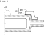
- FIG. 5 is a plan view of FIG. 4(b)
- FIG. 6 is a partial sectional view of FIG. 4 .
- the preliminary battery case 400 is configured such that gas is discharged in a direction indicated by arrows and the protective films 420 are attached to opposite end corner portions of a first side outer periphery 411 of the electrode assembly receiving portion oriented in the direction in which the gas is discharged.
- the protective film 420 is configured to have a structure in which an adhesive layer 421 including an adhesive material is located as the inner surface thereof and a film layer 422 including nylon or a PET-based compound is located at the outer surface of the adhesive layer 421. That is, the shape of the corner portion may be supported and maintained by the film layer, and the protective film may be stably attached and fixed to the outer surface of the corner portion by the adhesive layer.
- a method of adding the adhesive layer to the inner surface of the film layer is not particularly restricted.
- an adhesive may be applied to the inner surface of the film layer, or an adhesive material may be sprayed onto the inner surface of the film layer.
- FIG. 7 is a perspective view of a preliminary battery case to which a protective film according to a fifth embodiment is attached.
- the protective film 520 is formed so as to extend long along a first side outer periphery 511 of an electrode assembly receiving portion 510 including opposite end corner portions of the first side outer periphery 511 of the electrode assembly receiving portion.
- the protective film 520 shown in FIG. 7 includes an extension portion 522 extending to a sealing prearrangement portion so as to wrap the corner portions.
- the protective film may include no extending portion.
- the method of manufacturing the pouch-shaped battery cell according to the present invention includes a process of removing the protective film from the battery case. It is preferable that the adhesive layer attached to the inner surface of the film layer of the protective film be removed from the outer surface of the battery case together with the film layer.
- a pouch-shaped battery cell is manufactured in the state in which a corner portion of an electrode assembly receiving portion is in tight contact with the inner surface of a protective film. Consequently, the shape of the corner portion to which the protective film is attached may be maintained in a process of infusing an electrolytic solution, a process of discharging gas, a process of resealing an outer periphery of a preliminary battery case, and a process of removing an end of the outer periphery of a preliminary battery case.
- the outer surface of the corner portion may be brought into tight contact with the protective film via the adhesive layer.
- the shape of the corner portion is supported by the protective film such that the shape of the electrode assembly receiving portion formed in the preliminary battery case is maintained, as described above, it is possible to prevent the preliminary battery case from being crumpled or cracked in a process of manufacturing the pouch-shaped battery cell.
Landscapes
- Chemical & Material Sciences (AREA)
- Chemical Kinetics & Catalysis (AREA)
- Electrochemistry (AREA)
- General Chemical & Material Sciences (AREA)
- Engineering & Computer Science (AREA)
- Manufacturing & Machinery (AREA)
- Organic Chemistry (AREA)
- Sealing Battery Cases Or Jackets (AREA)
Description
- The present invention relates to a method of manufacturing a pouch-shaped battery cell using a protective film and a pouch-shaped battery cell manufactured using the same, and more particularly to a method of manufacturing a pouch-shaped battery cell using a protective film capable of manufacturing the pouch-shaped battery cell in the state in which the protective film is attached to the portion of the pouch-shaped battery cell that may be the most greatly deformed in a process of manufacturing the pouch-shaped battery cell, whereby it is possible to remarkably reduce a battery cell defect rate, and a pouch-shaped battery cell manufactured using the same.
- Based on the shape of a case, a lithium secondary battery is classified as a cylindrical battery, a prismatic battery, or a pouch-shaped battery. Each of the cylindrical battery and the prismatic battery is a battery having an electrode assembly mounted in a metal can, and the pouch-shaped battery is a battery having an electrode assembly mounted in a pouch-shaped case generally made of an aluminum laminate sheet. Among these batteries, the pouch-shaped battery, which can be stacked with high integration, has high energy density per unit weight, is inexpensive, and can be easily modified, has attracted considerable attention in recent years.
- The laminate sheet includes an outer coating layer configured to secure insulation thereof and to protect the surface thereof, a metal layer configured to block gas and moisture and to allow a battery case to be easily formed, and an inner resin layer for adhesion.
- In general, a process of forming an electrode assembly receiving portion, a degassing process, and a process of sealing the outer periphery of the battery case are performed in order to manufacture the pouch-shaped battery. While the above processes are performed, the metal layer of the laminate sheet may be damaged. In particular, stress is concentrated on corner portions of the electrode assembly receiving portion, in which the electrode assembly is received. As a result, there is a high possibility of cracks being formed at the corner portions of the electrode assembly receiving portion.
- In the case in which cracks are formed at the laminate sheet, as described above, an electrolytic solution may leak out of the battery, or external moisture may be introduced into the battery. Leakage of the electrolytic solution may induce ignition due to high-voltage ground fault current, whereby safety of the battery may be reduced.
- In connection therewith, Patent Document 1 discloses a crumple prevention portion formed at a sealing block used in a process of manufacturing a pouch-shaped secondary battery. In Patent Document 1, the sealing block, at which the crumple prevention portion is formed, is used to form sealing portions at outer peripheral corner portions of an electrode assembly receiving portion. It is possible to prevent crumples from being formed at the corner portions of the electrode assembly receiving portion by the provision of the sealing portions.
- Patent Document 2 discloses a pouch-shaped battery case configured such that, among outer peripheral sealing portions of a concave portion configured to receive an electrode assembly, a non-sealing portion is formed at the outer periphery through which an electrolytic solution is infused and gas is discharged, wherein ends of the outer periphery through which gas is discharged, excluding a central portion thereof, are sealed in advance.
- In Patent Document 1 and Patent Document 2, the sealing portions are formed in advance as structures for preventing crumples from being formed at the corner portions or the ends of the outer peripheries in the early stage of manufacture of the battery case. However, it is difficult to prevent the corner portions from being deformed by stress repeatedly concentrated thereon in subsequent degassing and resealing processes.
- Therefore, there is a high necessity for technology capable of preventing corner portions of an electrode assembly receiving portion from being deformed or cracked by force continuously applied to the corner portions while a process of manufacturing a pouch-shaped battery cell is performed.
-
- (Patent Document 1)
Korean Patent Application Publication No. 2019-0042801 (2019.04.25 - (Patent Document 2)
Korean Patent Application Publication No. 2019-0042800 (2019.04.25 - (Patent Document 3)
US 2014/011070 A1 - (Patent Document 4)
US 2018/241023 A1 - (Patent Document 5)
KR 2013 0092800 A - The present invention has been made in view of the above problems, and it is an object of the present invention to provide a method of manufacturing a pouch-shaped battery cell using a protective film capable of preventing deformation of corner portions of an electrode assembly receiving portion and maintaining the initial shape of the corner portions in a process of manufacturing the pouch-shaped battery cell and a pouch-shaped battery cell manufactured using the same.
- In order to accomplish the above object, a method of manufacturing a pouch-shaped battery cell according to the present invention includes (a) receiving an electrode assembly in a preliminary battery case and sealing other outer peripheries of the preliminary battery case excluding a first side outer periphery of the preliminary battery case, the first side outer periphery being configured to discharge gas therethrough, (b) attaching a protective film to at least one corner portion of an electrode assembly receiving portion, wherein the protective film has an adhesive layer comprising an adhesive material and a film layer comprising nylon or a PET-based compound, (c) performing an activation process and a degassing process, (d) sealing a first side outer periphery of the electrode assembly receiving portion, and (e) removing the protective film, wherein the inner surface of the protective film is attached to the outer surface of the corner portion of the electrode assembly receiving portion in tight contact therewith without being crumpled in order to support the shape of the corner portion of the electrode assembly receiving portion.
- The corner portion may be a portion at which the bottom surface of the electrode assembly receiving portion and two adjacent side surfaces of the electrode assembly receiving portion are joined to each other, and the protective film may be attached to each of opposite end corner portions of the first side outer periphery of the electrode assembly receiving portion.
- The corner portion may be a portion at which the bottom surface of the electrode assembly receiving portion and two adjacent side surfaces of the electrode assembly receiving portion are joined to each other, and the protective film may be attached to each of all corner portions of the bottom surface of the electrode assembly receiving portion.
- The protective film may be attached so as to extend to a sealing prearrangement portion of step (d).
- The protective film may be formed so as to have a size and a shape corresponding respectively to the size and the shape of the corner portion of the electrode assembly receiving portion.
- The protective film may be formed so as to have a size and a shape corresponding respectively to the sizes and the shapes of the corner portion of the electrode assembly receiving portion and the sealing prearrangement portion extending from the corner portion.
- The adhesive layer of the protective film may be attached to the outer surface of the corner portion of the electrode assembly receiving portion in order to maintain the shape of the corner portion of the electrode assembly receiving portion in step (c) and step (d).
- The protective film may be attached along the first side outer periphery of the electrode assembly receiving portion comprising opposite end corner portions of the first side outer periphery.
- The method may include a process of temporarily sealing the first side outer periphery of the preliminary battery case before the activation process of step (c) is performed.
- The method may include removing an end of the first side outer periphery of the preliminary battery case and folding the first side outer periphery and a third side outer periphery between step (d) and step (e).
- The present invention provides a pouch-shaped battery cell manufactured using the method of manufacturing the pouch-shaped battery cell and a battery module including the pouch-shaped battery cell.
-
-
FIG. 1 is a view showing a process of manufacturing a pouch-shaped battery cell according to the present invention. -
FIG. 2 is a perspective view of a preliminary battery case to which a protective film according to a first embodiment is attached. -
FIG. 3 is a perspective view of a preliminary battery case to which a protective film according to a second embodiment is attached. -
FIG. 4 is a perspective view of a preliminary battery case to which a protective film according to each of a third embodiment and a fourth embodiment is attached. -
FIG. 5 is a plan view ofFIG. 4(b) . -
FIG. 6 is a partial sectional view ofFIG. 4 . -
FIG. 7 is a perspective view of a preliminary battery case to which a protective film according to a fifth embodiment is attached. - Now, preferred embodiments of the present invention will be described in detail with reference to the accompanying drawings such that the preferred embodiments of the present invention can be easily implemented by a person having ordinary skill in the art to which the present invention pertains. In describing the principle of operation of the preferred embodiments of the present invention in detail, however, a detailed description of known functions and configurations incorporated herein will be omitted when the same may obscure the subject matter of the present invention.
- In addition, the same reference numbers will be used throughout the drawings to refer to parts that perform similar functions or operations. In the case in which one part is said to be connected to another part in the specification, not only may the one part be directly connected to the other part, but also, the one part may be indirectly connected to the other part via a further part. In addition, that a certain element is included does not mean that other elements are excluded, but means that such elements may be further included unless mentioned otherwise.
- A description to embody elements through limitation or addition may be applied to all inventions, unless particularly restricted, and does not limit a specific invention.
- Hereinafter, embodiments of the present invention will be described in detail with reference to the accompanying drawings.
-
FIG. 1 is a view showing a process of manufacturing a pouch-shaped battery cell according to the present invention. - Referring to
FIG. 1 , the method of manufacturing the pouch-shaped battery cell according to the present invention includes a step of receiving anelectrode assembly 105 in an electrodeassembly receiving portion 110 formed in apreliminary battery case 100 and sealing a second sideouter periphery 102, a third sideouter periphery 103, and a fourth sideouter periphery 104 of the preliminary battery case excluding a first sideouter periphery 101 of the preliminary battery case, through which gas is discharged, a step of attaching aprotective film 120 to at least one corner portion of the electrode assembly receiving portion, a step of performing an activation process and a degassing process, a step of sealing a first sideouter periphery 111 of the electrodeassembly receiving portion 110, and a step of removing theprotective film 120. - A process of temporarily sealing the first side
outer periphery 101 of the preliminary battery case may be further included before the activation process is performed. - In addition, a step of removing an end of the first side
outer periphery 101 of the preliminary battery case and folding the first sideouter periphery 101 and the third sideouter periphery 103 may be further included after the step of sealing of the first sideouter periphery 111 of the electrodeassembly receiving portion 110 and before the step of removing theprotective film 120. - That is, the protective film is maintained attached to the corner portion until the first side outer periphery and the third side outer periphery are folded after the other outer peripheries of the preliminary battery case excluding the first side outer periphery are sealed. After the first side outer periphery and the third side outer periphery are folded, the protective film is removed from the corner portion of the electrode assembly receiving portion, whereby the pouch-shaped battery cell is manufactured.
- Alternatively, after the end of the first side outer periphery of the preliminary battery case is removed, the protective film may be removed in the state in which the step of folding the first side
outer periphery 101 and the third sideouter periphery 103 is omitted. - The first side outer periphery and the third side outer periphery mean outer peripheries oriented in directions in which no electrode terminals protrude.
- The corner portion is a portion at which the bottom surface of the electrode assembly receiving portion and two adjacent side surfaces of the electrode assembly receiving portion are joined to each other. The corner portion mentioned in this specification refers to the same portion as the above mentioned portion.
- The inner surface of the
protective film 120 is attached to the outer surface of the corner portion of the electrode assembly receiving portion in tight contact therewith without being crumpled in order to support the shape of the corner portion of the electrode assembly receiving portion. Even in the case in which external force is applied to the preliminary battery case to the extent to which the preliminary battery case is crumpled or deformed in a process of manufacturing the pouch-shaped battery cell, therefore, the shape of the corner portion may be maintained. -
FIG. 2 is a perspective view of a preliminary battery case to which a protective film according to a first embodiment is attached. - Referring to
FIG. 2 ,protective films 120 are attached to oppositeend corner portions 112 of a first sideouter periphery 111 of an electrodeassembly receiving portion 110. - Each of the
protective films 120 has a three-dimensional cubic shape, and is formed so as to have a size and shape corresponding respectively to the size and shape of a corresponding one of thecorner portions 112 of the electrode assembly receiving portion. The inner surface of theprotective film 120 and the outer surface of the corner portion are completely attached to each other in tight contact with each other without being crumpled. - Even in the case in which external force is applied to the preliminary battery case to the extent to which the preliminary battery case is contracted or twisted in a process of manufacturing a pouch-shaped battery cell, therefore, the inner surface of the protective film is maintained attached to the corner portion in tight contact therewith. Consequently, it is possible to prevent the corner portion from being crumpled or cracked.
-
FIG. 3 is a perspective view of a preliminary battery case to which a protective film according to a second embodiment is attached. - Referring to
FIG. 3 , thepreliminary battery case 200 includes afirst case 200a and asecond case 200b, outer peripheries of which are sealed by thermal fusion, and each of thefirst case 200a and thesecond case 200b has an electrodeassembly receiving portion 210 formed therein. - Also, in a degassing process, which is included in a process of manufacturing a pouch-shaped battery cell, a method of decompressing the preliminary battery case into a vacuum state may be used. At this time, the preliminary battery case may be deformed while being contracted. Such deformation may occur the most greatly at a first side
outer periphery 211 of the electrode assembly receiving portion, which is oriented in a direction in which gas is discharged. However, the other outer peripheries are deformed although there is a difference in degree. - In particular, a third side
outer periphery 203 may be deformed more than a second sideouter periphery 202 and a fourth sideouter periphery 204, since the third side outer periphery is an outer periphery in a major-axis direction of an electrode assembly. - Therefore,
FIG. 3 shows the state in which protective films are further disposed at oppositeend corner portions 212 of the third sideouter periphery 203 of the electrode assembly receiving portion, which is opposite the first sideouter periphery 211 of the electrode assembly receiving portion, i.e. theprotective films 220 are attached to all corner portions of the bottom surface of the electrode assembly receiving portion. In the case in which theprotective films 220 are attached to all of thecorner portions 212, as described above, it is possible to prevent deformation of the second side outer periphery to the fourth side outer periphery as well as the first side outer periphery. - The
protective film 220 shown inFIG. 3 is different from theprotective film 120 ofFIG. 2 in that the planar shape of the portion of the protective film that is added to the bottom surface of the electrode assembly receiving portion is not a quadrangular shape but is a "┐" shape. - In addition, the
protective film 220 further includes anextension portion 222 not only configured to wrap thecorner portion 212 but also extending to asealing prearrangement portion 214, whereby the protective film is formed so as to have a size and shape corresponding respectively to the sizes and shapes of the corner portion and thesealing prearrangement portion 214 extending from the corner portion. In the case in which theprotective film 220 is attached, therefore, it is possible to additionally prevent deformation of a connection portion between aside wall 215 of the electrode assembly receiving portion and thesealing prearrangement portion 214. -
FIG. 4 is a perspective view of a preliminary battery case to which a protective film according to each of a third embodiment and a fourth embodiment is attached. - Referring to
FIG. 4 , theprotective film 320 shown inFIG. 4(a) is configured such that the portion of the protective film oriented in an x-axis direction, which is a major-axis direction of an electrode assembly receiving portion, is longer than the portion of the protective film oriented in a y-axis direction, which is a minor-axis direction of the electrode assembly receiving portion, compared to theprotective film 220 ofFIG. 3 . - In consideration of the fact that the major-axis direction outer periphery of the electrode assembly receiving portion is deformed more than the minor-axis direction outer periphery of the electrode assembly receiving portion, the length of the protective film attached to the portion of the preliminary battery case that is further deformed is increased, whereby it is possible to improve the effect of preventing deformation of the preliminary battery case.
- The
protective film 420 shown inFIG. 4(b) is configured such that the planar shape of the portion of the protective film that wraps the bottom surface of an electrode assembly receiving portion is a triangular shape. In consideration of the fact that deformation of a corner portion of the electrode assembly receiving portion generally occurs at a side wall of the electrode assembly receiving portion, it is possible to achieve a desired effect even in the case in which a structure like theprotective film 420 is used. - The
protective film 320 has a dual-layer structure including anadhesive layer 321 constituting the inner surface thereof and afilm layer 322 constituting the outer surface thereof, and theprotective film 420 has a dual-layer structure including anadhesive layer 421 constituting the inner surface thereof and afilm layer 422 constituting the outer surface thereof. - In a concrete example, the thickness of the adhesive layer may be 5 µm to 30 µm, specifically 5 µm to 20 µm, more specifically 10 µm. The thickness of the film layer may be 50 µm to 150 µm, specifically 50 µm to 100 µm, more specifically 50 µm to 70 µm.
- The overall elongation of the protective film may be within 10%. In the case in which the elongation of the protective film is greater than 10%, the preliminary battery case deformed in degassing and resealing processes may be lengthened while the shape of the preliminary battery case may not be fixed, which is undesirable. In the case in which the elongation of the protective film is too small, internal stress of the preliminary battery case against deformation of the preliminary battery case may be increased, whereby the preliminary battery case may be fractured or cracked, which is also undesirable.
- Each of the
protective films FIG. 4 includes no extension portion extending to an outer peripheral sealing portion of the electrode assembly receiving portion. Of course, however, an extension portion may be included, unlike what is shown. -
FIG. 5 is a plan view ofFIG. 4(b) , andFIG. 6 is a partial sectional view ofFIG. 4 . - Referring to
FIGS. 5 and6 , thepreliminary battery case 400 is configured such that gas is discharged in a direction indicated by arrows and theprotective films 420 are attached to opposite end corner portions of a first sideouter periphery 411 of the electrode assembly receiving portion oriented in the direction in which the gas is discharged. - The
protective film 420 is configured to have a structure in which anadhesive layer 421 including an adhesive material is located as the inner surface thereof and afilm layer 422 including nylon or a PET-based compound is located at the outer surface of theadhesive layer 421. That is, the shape of the corner portion may be supported and maintained by the film layer, and the protective film may be stably attached and fixed to the outer surface of the corner portion by the adhesive layer. - A method of adding the adhesive layer to the inner surface of the film layer is not particularly restricted. For example, an adhesive may be applied to the inner surface of the film layer, or an adhesive material may be sprayed onto the inner surface of the film layer.
-
FIG. 7 is a perspective view of a preliminary battery case to which a protective film according to a fifth embodiment is attached. - Referring to
FIG. 7 , theprotective film 520 is formed so as to extend long along a first sideouter periphery 511 of an electrodeassembly receiving portion 510 including opposite end corner portions of the first sideouter periphery 511 of the electrode assembly receiving portion. - Consequently, it is possible to improve the effect of preventing deformation of the first side outer periphery, which is greatly deformed in a process of manufacturing a pouch-shaped battery cell.
- The
protective film 520 shown inFIG. 7 includes anextension portion 522 extending to a sealing prearrangement portion so as to wrap the corner portions. Of course, however, the protective film may include no extending portion. - The method of manufacturing the pouch-shaped battery cell according to the present invention includes a process of removing the protective film from the battery case. It is preferable that the adhesive layer attached to the inner surface of the film layer of the protective film be removed from the outer surface of the battery case together with the film layer.
- In the method of manufacturing the pouch-shaped battery cell according to the present invention and the pouch-shaped battery cell manufactured using the same, as described above, it is possible to prevent cracks from being formed at the corner portion of the electrode assembly receiving portion in the manufacturing process, whereby it is possible to reduce a battery cell defect rate and at the same time to prevent a possibility of ignition due to infusion of an electrolytic solution.
- Those skilled in the art to which the present invention pertains will appreciate that various applications and modifications are possible within the scope of the appended claims.
-
- 100, 200, 400: Preliminary battery cases
- 101: First side outer periphery of preliminary battery case
- 102, 202: Second side outer peripheries
- 103, 203: Third side outer peripheries
- 104, 204: Fourth side outer peripheries
- 105: Electrode assembly
- 110, 210, 510: Electrode assembly receiving portions
- 111, 211, 411, 511: First side outer peripheries of electrode assembly receiving portions
- 112, 212: Corner portions
- 120, 220, 320, 420, 520: Protective films
- 200a: First case
- 200b: Second case
- 214: Sealing prearrangement portion
- 215: Side wall of electrode assembly receiving portion
- 222, 522: Extension portions
- 321, 421: Adhesive layers
- 322, 422: Film layers
- As is apparent from the above description, in the present invention, a pouch-shaped battery cell is manufactured in the state in which a corner portion of an electrode assembly receiving portion is in tight contact with the inner surface of a protective film. Consequently, the shape of the corner portion to which the protective film is attached may be maintained in a process of infusing an electrolytic solution, a process of discharging gas, a process of resealing an outer periphery of a preliminary battery case, and a process of removing an end of the outer periphery of a preliminary battery case.
- Also, in the case in which an adhesive layer is provided at the inner surface of the protective film, the outer surface of the corner portion may be brought into tight contact with the protective film via the adhesive layer.
- Since the shape of the corner portion is supported by the protective film such that the shape of the electrode assembly receiving portion formed in the preliminary battery case is maintained, as described above, it is possible to prevent the preliminary battery case from being crumpled or cracked in a process of manufacturing the pouch-shaped battery cell.
- Consequently, it is possible to reduce a pouch-shaped battery cell defect rate and to reduce a danger of ignition due to ground fault current, which may be induced by leakage of the electrolytic solution.
Claims (10)
- A method of manufacturing a pouch-shaped battery cell, the method comprising:(a) receiving an electrode assembly (105) in a preliminary battery case (100, 200, 400) and sealing other outer peripheries of the preliminary battery case (100, 200, 400) excluding a first side outer periphery (101) of the preliminary battery case (100, 200, 400), the first side outer periphery (101) being configured to discharge gas therethrough;(b) attaching a protective film (120, 220, ..., 520) to at least one corner portion (112, 212) of an electrode assembly receiving portion (110, 210, 510);
wherein the protective film has an adhesive layer (321, 421) comprising an adhesive material and a film layer (322, 422) comprising nylon or a PET-based compound;(c) performing an activation process and a degassing process;(d) sealing the first side outer periphery (111, 211, 411, 511) of the electrode assembly receiving portion (110, 210, 510); and(e) removing the protective film (120, 220, ..., 520),wherein an inner surface of the protective film (120, 220, ..., 520) is attached to an outer surface of the corner portion (112, 212) of the electrode assembly receiving portion (110, 210, 510) in tight contact therewith without being crumpled in order to support a shape of the corner portion (112, 212) of the electrode assembly receiving portion (110, 210, 510). - The method according to claim 1, whereinthe corner portion (112, 212) is a portion at which a bottom surface of the electrode assembly receiving portion (110, 210, 510) and two adjacent side surfaces of the electrode assembly receiving portion (110, 210, 510) are joined to each other, andthe protective film (120, 220, ..., 520) is attached to each of opposite end corner portions (112, 212) of the first side outer periphery (111, 211, 411, 511) of the electrode assembly receiving portion.
- The method according to claim 1, whereinthe corner portion (112, 212) is a portion at which a bottom surface of the electrode assembly receiving portion (110, 210, 510) and two adjacent side surfaces of the electrode assembly receiving portion (110, 210, 510) are joined to each other, andthe protective film (120, 220, ..., 520) is attached to each of all corner portions of the bottom surface of the electrode assembly receiving portion (110, 210, 510).
- The method according to claim 1, wherein the protective film (120, 220, ..., 520) is attached so as to extend to a sealing prearrangement portion (214) of step (d).
- The method according to claim 1, wherein the protective film (120, 220, ..., 520) is formed so as to have a size and a shape corresponding respectively to a size and a shape of the corner portion (112, 212) of the electrode assembly receiving portion (110, 210, 510).
- The method according to claim 4, wherein the protective film (120, 220, ..., 520) is formed so as to have a size and a shape corresponding respectively to sizes and shapes of the corner portion (112, 212) of the electrode assembly receiving portion (110, 210, 510) and the sealing prearrangement portion (214) extending from the corner portion (112, 212).
- The method according to claim 1, wherein the adhesive layer (321, 421) of the protective film (120, 220, ..., 520) is attached to the outer surface of the corner portion (112, 212) of the electrode assembly receiving portion (110, 210, 510) in order to maintain the shape of the corner portion of the electrode assembly receiving portion in step (c) and step (d).
- The method according to claim 1, wherein the protective film (120, 220, ..., 520) is attached along the first side outer periphery (111, 211, 411, 511) of the electrode assembly receiving portion (110, 210, 510) comprising opposite end corner portions (112, 212) of the first side outer periphery.
- The method according to claim 1, comprising a process of temporarily sealing the first side outer periphery (111, 211, 411, 511) of the preliminary battery case before the activation process of step (c) is performed.
- The method according to claim 1, comprising removing an end of the first side outer periphery (111, 211, 411, 511) of the preliminary battery case (100, 200, 400) and folding the first side outer periphery and a third side outer periphery between step (d) and step (e).
Applications Claiming Priority (2)
| Application Number | Priority Date | Filing Date | Title |
|---|---|---|---|
| KR1020190162521A KR102835332B1 (en) | 2019-12-09 | 2019-12-09 | Method for Preparing Pouch-type Battery Cell Using Protective Film and Pouch-type Battery Cell Manufactured therewith |
| PCT/KR2020/014971 WO2021118057A1 (en) | 2019-12-09 | 2020-10-29 | Method for manufacturing pouch-type battery cell using protection film and pouch-type battery cell manufactured using same |
Publications (3)
| Publication Number | Publication Date |
|---|---|
| EP4040579A1 EP4040579A1 (en) | 2022-08-10 |
| EP4040579A4 EP4040579A4 (en) | 2024-04-17 |
| EP4040579B1 true EP4040579B1 (en) | 2025-06-11 |
Family
ID=76328997
Family Applications (1)
| Application Number | Title | Priority Date | Filing Date |
|---|---|---|---|
| EP20898352.8A Active EP4040579B1 (en) | 2019-12-09 | 2020-10-29 | Method of manufacturing pouch-shaped battery cell using protective film and pouch-shaped battery cell manufactured using the same |
Country Status (8)
| Country | Link |
|---|---|
| US (1) | US12199232B2 (en) |
| EP (1) | EP4040579B1 (en) |
| KR (1) | KR102835332B1 (en) |
| CN (1) | CN114270603B (en) |
| ES (1) | ES3036315T3 (en) |
| HU (1) | HUE072460T2 (en) |
| PL (1) | PL4040579T3 (en) |
| WO (1) | WO2021118057A1 (en) |
Families Citing this family (6)
| Publication number | Priority date | Publication date | Assignee | Title |
|---|---|---|---|---|
| KR102900633B1 (en) * | 2022-01-14 | 2025-12-15 | 주식회사 엘지에너지솔루션 | Pouch-type secondary battery and manufacturing method therof |
| KR102585007B1 (en) | 2022-01-24 | 2023-10-10 | 김찬식 | Multilayer film for cell pouch of secondary battery and producing method thereof |
| AU2023360872A1 (en) | 2022-10-12 | 2025-03-06 | Lg Energy Solution, Ltd. | Battery module, and battery pack and energy storage system including the same |
| KR20250075366A (en) * | 2023-11-21 | 2025-05-28 | 주식회사 엘지에너지솔루션 | Sealing device and method of sealing secondary battery |
| KR20250128088A (en) * | 2024-02-20 | 2025-08-27 | 삼성에스디아이 주식회사 | Rechargeable battery |
| KR20260051699A (en) * | 2024-10-10 | 2026-04-17 | 삼성에스디아이 주식회사 | Secondary battery and method for manufacturing same |
Family Cites Families (25)
| Publication number | Priority date | Publication date | Assignee | Title |
|---|---|---|---|---|
| CN1303718C (en) | 1999-03-26 | 2007-03-07 | 松下电器产业株式会社 | laminated sheet packaged battery |
| JP4281302B2 (en) * | 2002-07-16 | 2009-06-17 | 日本電気株式会社 | Method for manufacturing film outer package |
| KR101108447B1 (en) * | 2006-08-28 | 2012-02-08 | 주식회사 엘지화학 | Manufacturing method of pouch type secondary battery excellent in sealing property |
| US8945764B2 (en) * | 2007-07-19 | 2015-02-03 | Lg Chem, Ltd. | Battery pack of large capacity |
| WO2009113634A1 (en) * | 2008-03-14 | 2009-09-17 | 日本電気株式会社 | Film-covered electrical device and assembled battery |
| KR101334623B1 (en) * | 2010-12-02 | 2013-11-29 | 주식회사 엘지화학 | Degassing Method of Secondary Battery Using Centrifugal Force |
| DE102011013618A1 (en) * | 2011-03-11 | 2012-09-13 | Li-Tec Battery Gmbh | Energy storage device |
| KR101680755B1 (en) * | 2012-02-13 | 2016-11-30 | 에스케이이노베이션 주식회사 | Battery cell |
| KR20130113301A (en) * | 2012-04-05 | 2013-10-15 | 주식회사 엘지화학 | Battery cell of stair-like structure |
| KR101623106B1 (en) | 2013-05-06 | 2016-05-20 | 주식회사 엘지화학 | Formimg apparatus for pouch film |
| KR20150010481A (en) * | 2013-07-19 | 2015-01-28 | 삼성에스디아이 주식회사 | Pouch battery and manufacturing method thereof |
| KR101587322B1 (en) * | 2013-08-05 | 2016-01-20 | 주식회사 엘지화학 | Correction apparatus of zigzag line for electrode assembly |
| KR101538272B1 (en) * | 2014-01-06 | 2015-07-22 | 주식회사 엘지화학 | Stepped battery, method for manufacturing the same, and device thereof |
| US20170166373A1 (en) | 2014-07-29 | 2017-06-15 | Sekisui Chemical Co., Ltd. | Film molded article, film packaged body using the same, manufacturing method for film molded article and manufacturing method for film packaged body |
| KR102324360B1 (en) * | 2015-08-17 | 2021-11-09 | 에스케이이노베이션 주식회사 | Secondary battery and secondary battery module including the same |
| KR102112670B1 (en) | 2015-10-28 | 2020-05-19 | 주식회사 엘지화학 | Battery Cell of Venting Structure Using Taping |
| KR102123078B1 (en) * | 2016-05-24 | 2020-06-15 | 주식회사 엘지화학 | Manufacturin method of rechargeable battery |
| US20180041023A1 (en) | 2016-08-05 | 2018-02-08 | Jesus Juvenal Farfan | Electrical safety control device |
| KR102421369B1 (en) | 2016-11-25 | 2022-07-15 | 주식회사 엘지에너지솔루션 | A method of manufacturing pouch-typed secondary battery and Jig for used therefor |
| KR102079781B1 (en) * | 2016-12-15 | 2020-02-20 | 주식회사 엘지화학 | Method of Injecting Electrolyte Solution for Pouch Secondary Battery using Gap Control Jig |
| KR102263429B1 (en) * | 2017-03-22 | 2021-06-11 | 주식회사 엘지에너지솔루션 | Process of Manufacturing Battery Cell Having Auxiliary Sealing Part for Preventing Crack of Battery Case |
| KR102347901B1 (en) | 2017-10-17 | 2022-01-06 | 주식회사 엘지에너지솔루션 | Pouch-Type Battery Case Having Structure to Prevent Crack and Method for Preparing the Same |
| KR102443908B1 (en) | 2017-10-17 | 2022-09-16 | 주식회사 엘지에너지솔루션 | Method for manufacturing pouch-type secondary battery including pattern sealing step |
| KR102347884B1 (en) | 2017-10-17 | 2022-01-06 | 주식회사 엘지에너지솔루션 | Sealing Block to Prevent Crack of Pouch-Type Secondary Battery, Pouch-Type Battery Case and Sealing Method for Pouch-Type Battery Case Using thereof |
| KR102394495B1 (en) | 2017-11-14 | 2022-05-04 | 주식회사 엘지에너지솔루션 | The Pouch For Secondary Battery, The Secondary Battery And The Method For Manufacturing Thereof |
-
2019
- 2019-12-09 KR KR1020190162521A patent/KR102835332B1/en active Active
-
2020
- 2020-10-29 EP EP20898352.8A patent/EP4040579B1/en active Active
- 2020-10-29 CN CN202080059409.4A patent/CN114270603B/en active Active
- 2020-10-29 HU HUE20898352A patent/HUE072460T2/en unknown
- 2020-10-29 PL PL20898352.8T patent/PL4040579T3/en unknown
- 2020-10-29 ES ES20898352T patent/ES3036315T3/en active Active
- 2020-10-29 US US17/770,383 patent/US12199232B2/en active Active
- 2020-10-29 WO PCT/KR2020/014971 patent/WO2021118057A1/en not_active Ceased
Also Published As
| Publication number | Publication date |
|---|---|
| CN114270603B (en) | 2024-02-13 |
| PL4040579T3 (en) | 2025-09-22 |
| ES3036315T3 (en) | 2025-09-17 |
| HUE072460T2 (en) | 2025-11-28 |
| KR102835332B1 (en) | 2025-07-17 |
| US20220376288A1 (en) | 2022-11-24 |
| US12199232B2 (en) | 2025-01-14 |
| EP4040579A4 (en) | 2024-04-17 |
| WO2021118057A1 (en) | 2021-06-17 |
| KR20210072322A (en) | 2021-06-17 |
| EP4040579A1 (en) | 2022-08-10 |
| CN114270603A (en) | 2022-04-01 |
Similar Documents
| Publication | Publication Date | Title |
|---|---|---|
| US12199232B2 (en) | Method of manufacturing pouch-shaped battery cell using protective film and pouch-shaped battery cell manufactured using the same | |
| US10923758B2 (en) | Electrode assembly having step, secondary battery, battery pack and device including electrode assembly, and method of manufacturing electrode assembly | |
| US10673033B2 (en) | Gasket and diaphragm for electrochemical cell | |
| US8574746B2 (en) | Film-covered electrical device and assembled battery | |
| EP4007044B1 (en) | Method of manufacturing pouch-shaped battery cell using fixing jig and pouch-shaped battery cell manufactured using the same | |
| US20110086259A1 (en) | Water-resistant pouch type secondary cell | |
| CN110495008A (en) | Crack-resistant sealing block for pouch-shaped secondary battery, pouch-shaped battery case manufactured using the same, and method of sealing pouch-shaped battery case | |
| EP4191761B1 (en) | Battery cell and battery cell manufacturing apparatus | |
| EP4037071A1 (en) | Pouch-type secondary battery, battery pack, and method for manufacturing pouch-type secondary battery | |
| US9871267B2 (en) | Laminated battery and manufacturing method therefor | |
| US12341202B2 (en) | Pouch type secondary battery, battery pack, and method for manufacturing pouch type secondary battery | |
| JP2018006182A (en) | Film-covered battery | |
| CN107851742A (en) | Battery | |
| KR102890293B1 (en) | Secondary battery and device including the same | |
| US20220384922A1 (en) | Electrode Assembly, Secondary Battery and Method for Manufacturing the Same | |
| CA2829304A1 (en) | Stress relieve body to prevent cell seal failure during assembly | |
| JP7344123B2 (en) | Manufacturing method of power storage module and power storage module | |
| KR100624933B1 (en) | Lithium polymer battery | |
| EP3493315B1 (en) | Electrode assembly, secondary battery including the electrode assembly, and method for manufacturing the electrode assembly | |
| KR20250168803A (en) | Secondary battery | |
| CN117157789A (en) | Electrode assembly and battery cell including the same |
Legal Events
| Date | Code | Title | Description |
|---|---|---|---|
| STAA | Information on the status of an ep patent application or granted ep patent |
Free format text: STATUS: THE INTERNATIONAL PUBLICATION HAS BEEN MADE |
|
| PUAI | Public reference made under article 153(3) epc to a published international application that has entered the european phase |
Free format text: ORIGINAL CODE: 0009012 |
|
| STAA | Information on the status of an ep patent application or granted ep patent |
Free format text: STATUS: REQUEST FOR EXAMINATION WAS MADE |
|
| 17P | Request for examination filed |
Effective date: 20220504 |
|
| AK | Designated contracting states |
Kind code of ref document: A1 Designated state(s): AL AT BE BG CH CY CZ DE DK EE ES FI FR GB GR HR HU IE IS IT LI LT LU LV MC MK MT NL NO PL PT RO RS SE SI SK SM TR |
|
| DAV | Request for validation of the european patent (deleted) | ||
| DAX | Request for extension of the european patent (deleted) | ||
| REG | Reference to a national code |
Ref country code: DE Ref legal event code: R079 Free format text: PREVIOUS MAIN CLASS: H01M0050100000 Ipc: H01M0010040000 Ref country code: DE Ref legal event code: R079 Ref document number: 602020052756 Country of ref document: DE Free format text: PREVIOUS MAIN CLASS: H01M0050100000 Ipc: H01M0010040000 |
|
| A4 | Supplementary search report drawn up and despatched |
Effective date: 20240315 |
|
| RIC1 | Information provided on ipc code assigned before grant |
Ipc: H01M 50/105 20210101ALI20240311BHEP Ipc: H01M 10/04 20060101AFI20240311BHEP |
|
| GRAP | Despatch of communication of intention to grant a patent |
Free format text: ORIGINAL CODE: EPIDOSNIGR1 |
|
| STAA | Information on the status of an ep patent application or granted ep patent |
Free format text: STATUS: GRANT OF PATENT IS INTENDED |
|
| RIC1 | Information provided on ipc code assigned before grant |
Ipc: H01M 50/105 20210101ALI20241221BHEP Ipc: H01M 10/04 20060101AFI20241221BHEP |
|
| INTG | Intention to grant announced |
Effective date: 20250124 |
|
| P01 | Opt-out of the competence of the unified patent court (upc) registered |
Free format text: CASE NUMBER: APP_6052/2025 Effective date: 20250205 |
|
| GRAS | Grant fee paid |
Free format text: ORIGINAL CODE: EPIDOSNIGR3 |
|
| GRAA | (expected) grant |
Free format text: ORIGINAL CODE: 0009210 |
|
| STAA | Information on the status of an ep patent application or granted ep patent |
Free format text: STATUS: THE PATENT HAS BEEN GRANTED |
|
| AK | Designated contracting states |
Kind code of ref document: B1 Designated state(s): AL AT BE BG CH CY CZ DE DK EE ES FI FR GB GR HR HU IE IS IT LI LT LU LV MC MK MT NL NO PL PT RO RS SE SI SK SM TR |
|
| REG | Reference to a national code |
Ref country code: GB Ref legal event code: FG4D |
|
| REG | Reference to a national code |
Ref country code: CH Ref legal event code: EP |
|
| REG | Reference to a national code |
Ref country code: IE Ref legal event code: FG4D |
|
| REG | Reference to a national code |
Ref country code: DE Ref legal event code: R096 Ref document number: 602020052756 Country of ref document: DE |
|
| REG | Reference to a national code |
Ref country code: SE Ref legal event code: TRGR |
|
| REG | Reference to a national code |
Ref country code: ES Ref legal event code: FG2A Ref document number: 3036315 Country of ref document: ES Kind code of ref document: T3 Effective date: 20250917 |
|
| PG25 | Lapsed in a contracting state [announced via postgrant information from national office to epo] |
Ref country code: FI Free format text: LAPSE BECAUSE OF FAILURE TO SUBMIT A TRANSLATION OF THE DESCRIPTION OR TO PAY THE FEE WITHIN THE PRESCRIBED TIME-LIMIT Effective date: 20250611 |
|
| REG | Reference to a national code |
Ref country code: LT Ref legal event code: MG9D |
|
| PG25 | Lapsed in a contracting state [announced via postgrant information from national office to epo] |
Ref country code: NO Free format text: LAPSE BECAUSE OF FAILURE TO SUBMIT A TRANSLATION OF THE DESCRIPTION OR TO PAY THE FEE WITHIN THE PRESCRIBED TIME-LIMIT Effective date: 20250911 Ref country code: GR Free format text: LAPSE BECAUSE OF FAILURE TO SUBMIT A TRANSLATION OF THE DESCRIPTION OR TO PAY THE FEE WITHIN THE PRESCRIBED TIME-LIMIT Effective date: 20250912 |
|
| REG | Reference to a national code |
Ref country code: NL Ref legal event code: MP Effective date: 20250611 |
|
| PG25 | Lapsed in a contracting state [announced via postgrant information from national office to epo] |
Ref country code: BG Free format text: LAPSE BECAUSE OF FAILURE TO SUBMIT A TRANSLATION OF THE DESCRIPTION OR TO PAY THE FEE WITHIN THE PRESCRIBED TIME-LIMIT Effective date: 20250611 |
|
| PGFP | Annual fee paid to national office [announced via postgrant information from national office to epo] |
Ref country code: BE Payment date: 20250922 Year of fee payment: 6 Ref country code: GB Payment date: 20250922 Year of fee payment: 6 |
|
| PG25 | Lapsed in a contracting state [announced via postgrant information from national office to epo] |
Ref country code: HR Free format text: LAPSE BECAUSE OF FAILURE TO SUBMIT A TRANSLATION OF THE DESCRIPTION OR TO PAY THE FEE WITHIN THE PRESCRIBED TIME-LIMIT Effective date: 20250611 |
|
| PGFP | Annual fee paid to national office [announced via postgrant information from national office to epo] |
Ref country code: FR Payment date: 20250925 Year of fee payment: 6 |
|
| PGFP | Annual fee paid to national office [announced via postgrant information from national office to epo] |
Ref country code: SE Payment date: 20250923 Year of fee payment: 6 |
|
| PG25 | Lapsed in a contracting state [announced via postgrant information from national office to epo] |
Ref country code: RS Free format text: LAPSE BECAUSE OF FAILURE TO SUBMIT A TRANSLATION OF THE DESCRIPTION OR TO PAY THE FEE WITHIN THE PRESCRIBED TIME-LIMIT Effective date: 20250911 |
|
| PG25 | Lapsed in a contracting state [announced via postgrant information from national office to epo] |
Ref country code: LV Free format text: LAPSE BECAUSE OF FAILURE TO SUBMIT A TRANSLATION OF THE DESCRIPTION OR TO PAY THE FEE WITHIN THE PRESCRIBED TIME-LIMIT Effective date: 20250611 |
|
| PGFP | Annual fee paid to national office [announced via postgrant information from national office to epo] |
Ref country code: HU Payment date: 20251029 Year of fee payment: 6 |
|
| PG25 | Lapsed in a contracting state [announced via postgrant information from national office to epo] |
Ref country code: NL Free format text: LAPSE BECAUSE OF FAILURE TO SUBMIT A TRANSLATION OF THE DESCRIPTION OR TO PAY THE FEE WITHIN THE PRESCRIBED TIME-LIMIT Effective date: 20250611 |
|
| REG | Reference to a national code |
Ref country code: HU Ref legal event code: AG4A Ref document number: E072460 Country of ref document: HU |
|
| PG25 | Lapsed in a contracting state [announced via postgrant information from national office to epo] |
Ref country code: PT Free format text: LAPSE BECAUSE OF FAILURE TO SUBMIT A TRANSLATION OF THE DESCRIPTION OR TO PAY THE FEE WITHIN THE PRESCRIBED TIME-LIMIT Effective date: 20251013 |
|
| REG | Reference to a national code |
Ref country code: AT Ref legal event code: MK05 Ref document number: 1802983 Country of ref document: AT Kind code of ref document: T Effective date: 20250611 |
|
| PG25 | Lapsed in a contracting state [announced via postgrant information from national office to epo] |
Ref country code: IS Free format text: LAPSE BECAUSE OF FAILURE TO SUBMIT A TRANSLATION OF THE DESCRIPTION OR TO PAY THE FEE WITHIN THE PRESCRIBED TIME-LIMIT Effective date: 20251011 |
|
| PGFP | Annual fee paid to national office [announced via postgrant information from national office to epo] |
Ref country code: DE Payment date: 20250922 Year of fee payment: 6 |
|
| PG25 | Lapsed in a contracting state [announced via postgrant information from national office to epo] |
Ref country code: AT Free format text: LAPSE BECAUSE OF FAILURE TO SUBMIT A TRANSLATION OF THE DESCRIPTION OR TO PAY THE FEE WITHIN THE PRESCRIBED TIME-LIMIT Effective date: 20250611 Ref country code: SM Free format text: LAPSE BECAUSE OF FAILURE TO SUBMIT A TRANSLATION OF THE DESCRIPTION OR TO PAY THE FEE WITHIN THE PRESCRIBED TIME-LIMIT Effective date: 20250611 |
|
| PG25 | Lapsed in a contracting state [announced via postgrant information from national office to epo] |
Ref country code: CZ Free format text: LAPSE BECAUSE OF FAILURE TO SUBMIT A TRANSLATION OF THE DESCRIPTION OR TO PAY THE FEE WITHIN THE PRESCRIBED TIME-LIMIT Effective date: 20250611 |
|
| PGFP | Annual fee paid to national office [announced via postgrant information from national office to epo] |
Ref country code: PL Payment date: 20250925 Year of fee payment: 6 |
|
| PG25 | Lapsed in a contracting state [announced via postgrant information from national office to epo] |
Ref country code: EE Free format text: LAPSE BECAUSE OF FAILURE TO SUBMIT A TRANSLATION OF THE DESCRIPTION OR TO PAY THE FEE WITHIN THE PRESCRIBED TIME-LIMIT Effective date: 20250611 |
|
| PG25 | Lapsed in a contracting state [announced via postgrant information from national office to epo] |
Ref country code: SK Free format text: LAPSE BECAUSE OF FAILURE TO SUBMIT A TRANSLATION OF THE DESCRIPTION OR TO PAY THE FEE WITHIN THE PRESCRIBED TIME-LIMIT Effective date: 20250611 |
|
| PGFP | Annual fee paid to national office [announced via postgrant information from national office to epo] |
Ref country code: ES Payment date: 20251117 Year of fee payment: 6 |
|
| PG25 | Lapsed in a contracting state [announced via postgrant information from national office to epo] |
Ref country code: RO Free format text: LAPSE BECAUSE OF FAILURE TO SUBMIT A TRANSLATION OF THE DESCRIPTION OR TO PAY THE FEE WITHIN THE PRESCRIBED TIME-LIMIT Effective date: 20250611 |
|
| REG | Reference to a national code |
Ref country code: DE Ref legal event code: R097 Ref document number: 602020052756 Country of ref document: DE |
|
| PG25 | Lapsed in a contracting state [announced via postgrant information from national office to epo] |
Ref country code: DK Free format text: LAPSE BECAUSE OF FAILURE TO SUBMIT A TRANSLATION OF THE DESCRIPTION OR TO PAY THE FEE WITHIN THE PRESCRIBED TIME-LIMIT Effective date: 20250611 |
|
| PG25 | Lapsed in a contracting state [announced via postgrant information from national office to epo] |
Ref country code: IT Free format text: LAPSE BECAUSE OF FAILURE TO SUBMIT A TRANSLATION OF THE DESCRIPTION OR TO PAY THE FEE WITHIN THE PRESCRIBED TIME-LIMIT Effective date: 20250611 |
|
| PLBE | No opposition filed within time limit |
Free format text: ORIGINAL CODE: 0009261 |
|
| STAA | Information on the status of an ep patent application or granted ep patent |
Free format text: STATUS: NO OPPOSITION FILED WITHIN TIME LIMIT |
|
| REG | Reference to a national code |
Ref country code: CH Ref legal event code: L10 Free format text: ST27 STATUS EVENT CODE: U-0-0-L10-L00 (AS PROVIDED BY THE NATIONAL OFFICE) Effective date: 20260423 |