EP4040538A1 - Negative electrode material, negative electrode comprising same, and negative electrode preparation method - Google Patents
Negative electrode material, negative electrode comprising same, and negative electrode preparation method Download PDFInfo
- Publication number
- EP4040538A1 EP4040538A1 EP20883580.1A EP20883580A EP4040538A1 EP 4040538 A1 EP4040538 A1 EP 4040538A1 EP 20883580 A EP20883580 A EP 20883580A EP 4040538 A1 EP4040538 A1 EP 4040538A1
- Authority
- EP
- European Patent Office
- Prior art keywords
- negative electrode
- electrode material
- silicon
- fluorinated
- respect
- Prior art date
- Legal status (The legal status is an assumption and is not a legal conclusion. Google has not performed a legal analysis and makes no representation as to the accuracy of the status listed.)
- Pending
Links
Images

Classifications
-
- H—ELECTRICITY
- H01—ELECTRIC ELEMENTS
- H01M—PROCESSES OR MEANS, e.g. BATTERIES, FOR THE DIRECT CONVERSION OF CHEMICAL ENERGY INTO ELECTRICAL ENERGY
- H01M4/00—Electrodes
- H01M4/02—Electrodes composed of, or comprising, active material
- H01M4/36—Selection of substances as active materials, active masses, active liquids
- H01M4/48—Selection of substances as active materials, active masses, active liquids of inorganic oxides or hydroxides
- H01M4/483—Selection of substances as active materials, active masses, active liquids of inorganic oxides or hydroxides for non-aqueous cells
-
- B—PERFORMING OPERATIONS; TRANSPORTING
- B82—NANOTECHNOLOGY
- B82Y—SPECIFIC USES OR APPLICATIONS OF NANOSTRUCTURES; MEASUREMENT OR ANALYSIS OF NANOSTRUCTURES; MANUFACTURE OR TREATMENT OF NANOSTRUCTURES
- B82Y30/00—Nanotechnology for materials or surface science, e.g. nanocomposites
-
- H—ELECTRICITY
- H01—ELECTRIC ELEMENTS
- H01M—PROCESSES OR MEANS, e.g. BATTERIES, FOR THE DIRECT CONVERSION OF CHEMICAL ENERGY INTO ELECTRICAL ENERGY
- H01M10/00—Secondary cells; Manufacture thereof
- H01M10/05—Accumulators with non-aqueous electrolyte
- H01M10/052—Li-accumulators
- H01M10/0525—Rocking-chair batteries, i.e. batteries with lithium insertion or intercalation in both electrodes; Lithium-ion batteries
-
- H—ELECTRICITY
- H01—ELECTRIC ELEMENTS
- H01M—PROCESSES OR MEANS, e.g. BATTERIES, FOR THE DIRECT CONVERSION OF CHEMICAL ENERGY INTO ELECTRICAL ENERGY
- H01M4/00—Electrodes
- H01M4/02—Electrodes composed of, or comprising, active material
- H01M4/13—Electrodes for accumulators with non-aqueous electrolyte, e.g. for lithium-accumulators; Processes of manufacture thereof
- H01M4/133—Electrodes based on carbonaceous material, e.g. graphite-intercalation compounds or CFx
-
- H—ELECTRICITY
- H01—ELECTRIC ELEMENTS
- H01M—PROCESSES OR MEANS, e.g. BATTERIES, FOR THE DIRECT CONVERSION OF CHEMICAL ENERGY INTO ELECTRICAL ENERGY
- H01M4/00—Electrodes
- H01M4/02—Electrodes composed of, or comprising, active material
- H01M4/13—Electrodes for accumulators with non-aqueous electrolyte, e.g. for lithium-accumulators; Processes of manufacture thereof
- H01M4/134—Electrodes based on metals, Si or alloys
-
- H—ELECTRICITY
- H01—ELECTRIC ELEMENTS
- H01M—PROCESSES OR MEANS, e.g. BATTERIES, FOR THE DIRECT CONVERSION OF CHEMICAL ENERGY INTO ELECTRICAL ENERGY
- H01M4/00—Electrodes
- H01M4/02—Electrodes composed of, or comprising, active material
- H01M4/36—Selection of substances as active materials, active masses, active liquids
- H01M4/38—Selection of substances as active materials, active masses, active liquids of elements or alloys
- H01M4/386—Silicon or alloys based on silicon
-
- H—ELECTRICITY
- H01—ELECTRIC ELEMENTS
- H01M—PROCESSES OR MEANS, e.g. BATTERIES, FOR THE DIRECT CONVERSION OF CHEMICAL ENERGY INTO ELECTRICAL ENERGY
- H01M4/00—Electrodes
- H01M4/02—Electrodes composed of, or comprising, active material
- H01M4/36—Selection of substances as active materials, active masses, active liquids
- H01M4/58—Selection of substances as active materials, active masses, active liquids of inorganic compounds other than oxides or hydroxides, e.g. sulfides, selenides, tellurides, halogenides or LiCoFy; of polyanionic structures, e.g. phosphates, silicates or borates
- H01M4/583—Carbonaceous material, e.g. graphite-intercalation compounds or CFx
- H01M4/5835—Comprising fluorine or fluoride salts
-
- H—ELECTRICITY
- H01—ELECTRIC ELEMENTS
- H01M—PROCESSES OR MEANS, e.g. BATTERIES, FOR THE DIRECT CONVERSION OF CHEMICAL ENERGY INTO ELECTRICAL ENERGY
- H01M4/00—Electrodes
- H01M4/02—Electrodes composed of, or comprising, active material
- H01M4/36—Selection of substances as active materials, active masses, active liquids
- H01M4/58—Selection of substances as active materials, active masses, active liquids of inorganic compounds other than oxides or hydroxides, e.g. sulfides, selenides, tellurides, halogenides or LiCoFy; of polyanionic structures, e.g. phosphates, silicates or borates
- H01M4/583—Carbonaceous material, e.g. graphite-intercalation compounds or CFx
- H01M4/587—Carbonaceous material, e.g. graphite-intercalation compounds or CFx for inserting or intercalating light metals
-
- H—ELECTRICITY
- H01—ELECTRIC ELEMENTS
- H01M—PROCESSES OR MEANS, e.g. BATTERIES, FOR THE DIRECT CONVERSION OF CHEMICAL ENERGY INTO ELECTRICAL ENERGY
- H01M4/00—Electrodes
- H01M4/02—Electrodes composed of, or comprising, active material
- H01M4/62—Selection of inactive substances as ingredients for active masses, e.g. binders, fillers
-
- H—ELECTRICITY
- H01—ELECTRIC ELEMENTS
- H01M—PROCESSES OR MEANS, e.g. BATTERIES, FOR THE DIRECT CONVERSION OF CHEMICAL ENERGY INTO ELECTRICAL ENERGY
- H01M4/00—Electrodes
- H01M4/02—Electrodes composed of, or comprising, active material
- H01M4/62—Selection of inactive substances as ingredients for active masses, e.g. binders, fillers
- H01M4/624—Electric conductive fillers
- H01M4/625—Carbon or graphite
-
- H—ELECTRICITY
- H01—ELECTRIC ELEMENTS
- H01M—PROCESSES OR MEANS, e.g. BATTERIES, FOR THE DIRECT CONVERSION OF CHEMICAL ENERGY INTO ELECTRICAL ENERGY
- H01M4/00—Electrodes
- H01M4/02—Electrodes composed of, or comprising, active material
- H01M2004/021—Physical characteristics, e.g. porosity, surface area
-
- H—ELECTRICITY
- H01—ELECTRIC ELEMENTS
- H01M—PROCESSES OR MEANS, e.g. BATTERIES, FOR THE DIRECT CONVERSION OF CHEMICAL ENERGY INTO ELECTRICAL ENERGY
- H01M4/00—Electrodes
- H01M4/02—Electrodes composed of, or comprising, active material
- H01M2004/026—Electrodes composed of, or comprising, active material characterised by the polarity
- H01M2004/027—Negative electrodes
-
- Y—GENERAL TAGGING OF NEW TECHNOLOGICAL DEVELOPMENTS; GENERAL TAGGING OF CROSS-SECTIONAL TECHNOLOGIES SPANNING OVER SEVERAL SECTIONS OF THE IPC; TECHNICAL SUBJECTS COVERED BY FORMER USPC CROSS-REFERENCE ART COLLECTIONS [XRACs] AND DIGESTS
- Y02—TECHNOLOGIES OR APPLICATIONS FOR MITIGATION OR ADAPTATION AGAINST CLIMATE CHANGE
- Y02E—REDUCTION OF GREENHOUSE GAS [GHG] EMISSIONS, RELATED TO ENERGY GENERATION, TRANSMISSION OR DISTRIBUTION
- Y02E60/00—Enabling technologies; Technologies with a potential or indirect contribution to GHG emissions mitigation
- Y02E60/10—Energy storage using batteries
Definitions
- This application relates to the electrochemical field, and in particular, to a negative electrode material, a negative electrode containing the negative electrode material, and a negative electrode manufacturing method.
- silicon has an extraordinarily high theoretical capacity. Therefore, in recent years, the research on silicon serving as a negative electrode material is explosively growing.
- silicon improves the energy density.
- cycling stability of silicon needs to be further improved.
- a failure of the silicon negative electrode material mainly stems from the following facts: huge volume expansion of silicon after lithiation; and a high reactivity between a silicon surface and an electrolyte. This continuously increases a thickness of a solid electrolyte interphase (SEI) film, continuously consumes reversible lithium, and leads to capacity fading.
- SEI solid electrolyte interphase
- This application discloses a negative electrode material, a negative electrode containing the negative electrode material, and a negative electrode manufacturing method to solve at least one problem in the related art to some extent.
- this application discloses a negative electrode material, including: a silicon-containing material, where a ratio B/A of a maximum value B in differentials dQ/dV with respect to 0.4V-0.55V to a maximum value A in differentials dQ/dV with respect to 0.2V-0.35V is approximately 1.0-3.0 when the negative electrode material is electrified in a delithiation direction in a case of charging and discharging a battery that includes a negative electrode made of the negative electrode material and used as a working electrode, metallic lithium used as a counter electrode, and an electrolyte containing a lithium-ion conductive substance, and in a case of plotting a curve of a relationship between a differential dQ/dV and a working electrode potential V, where the differential is obtained by differentiating a charge/discharge capacity Q with respect to the working electrode potential V.
- this application further discloses a negative electrode manufacturing method, including: forming a negative electrode containing a negative electrode material; and performing steps of lithiating and delithiating the negative electrode.
- the negative electrode material includes a silicon-containing material, and the silicon-containing material includes at least one of pure silicon, silicon carbon, a micron silicon alloy, or a silicon oxide.
- a ratio B/A of a maximum value B in differentials dQ/dV with respect to 0.4V-0.55V to a maximum value A in differentials dQ/dV with respect to 0.2V-0.35V is approximately 1.0-3.0 when the negative electrode material is electrified in a delithiation direction in a case of charging and discharging a battery that includes the negative electrode used as a working electrode, metallic lithium used as a counter electrode, and an electrolyte containing a lithium-ion conductive substance, and in a case of plotting a curve of a relationship between a differential dQ/dV and a working electrode potential V, where the differential is obtained by differentiating a charge/discharge capacity Q with respect to the working electrode potential V
- the ratio B/A of the negative electrode material is kept within approximately 1.0-3.0 by controlling a lithiation depth of the negative electrode.
- the silicon-containing material includes at least one of pure silicon, silicon carbon, a silicon alloy, or a silicon oxide.
- a ratio B/A is approximately 2.0 to 3.0 in a case that the silicon-containing material includes a silicon oxide.
- the silicon oxide is a silicon oxide denoted by a general formula SiO x , where 0 ⁇ x ⁇ 2.
- At least a part of an outer surface of a SiO x particle is coated with carbon.
- a median diameter of SiO x particles is D50 greater than 1 ⁇ m and less than 10 ⁇ m.
- a specific surface area of SiO x particles is less than 5 m 2 /g.
- the negative electrode material further includes a fluorocarbon, where the fluorocarbon includes at least one of fluorinated graphite, fluorinated hard carbon, fluorinated soft carbon, fluorinated carbon nanotube, or fluorinated graphene.
- a weight percent content of the fluorocarbon is less than or equal to approximately 20%.
- the pure silicon includes at least one of a micron particle, a nanoparticle, a nanowire, a nanofilm, or a nanosphere.
- this application further discloses a negative electrode containing any negative electrode material described above.
- this application further discloses an electrochemical apparatus, including any negative electrode described above.
- this application further discloses an electronic apparatus, including any electrochemical apparatus described above.
- a difference between two numerical values is less than or equal to ⁇ 10% of an average of the numerical values (such as less than or equal to ⁇ 5%, less than or equal to ⁇ 4%, less than or equal to ⁇ 3%, less than or equal to ⁇ 2%, less than or equal to ⁇ 1%, less than or equal to ⁇ 0.5%, less than or equal to ⁇ 0.1%, or less than or equal to ⁇ 0.05%), the two numerical values may be considered "substantially" the same.
- an amount, a ratio, or another numerical value is sometimes expressed in a range format herein. Understandably, such a range format is for convenience and brevity, and needs to be flexibly understood to include not only the numerical values explicitly specified in range limits, but also all individual numerical values or sub-ranges covered in the range as if each numerical value and each sub-range are explicitly specified.
- a list of items referred to by using the terms such as "at least one of”, “at least one in”, “at least one type of” or other similar terms may mean any combination of the listed items.
- the phrase “at least one of A or B” means: only A; only B; or, A and B.
- the phrase "at least one of A, B, or C” means: only A; only B; only C; A and B (excluding C); A and C (excluding B); B and C (excluding A); or, all of A, B and C.
- the item A may include a single component or multiple components.
- the item B may include a single component or multiple components.
- the item C may include a single component or multiple components.
- a battery that includes a negative electrode material including a silicon-containing material used as a working electrode, metallic lithium used as a counter electrode, and an electrolyte containing a lithium-ion conductive substance is charged and discharged, and a curve of a relationship (V-dQ/dV) between a differential dQ/dV and a working electrode potential V is plotted, where the differential is obtained by differentiating a charge/discharge capacity Q with respect to the working electrode potential V.
- a maximum value in differentials dQ/dV with respect to approximately 0.2V-0.35V is A, and a maximum value in differentials dQ/dV with respect to approximately 0.4V-0.55V is B.
- the research by the inventor of this application shows that by selectively controlling a lithiation degree of a negative electrode containing the negative electrode material, the ratio B/A is kept within approximately 1.0-3.0, and the cycling performance of the negative electrode material is greatly improved.
- the research by the inventor of this application shows that by introducing a fluorocarbon into the negative electrode material including a silicon-containing material, the cycling performance of the negative electrode material can be further improved.
- This application discloses a negative electrode material, a negative electrode containing the negative electrode material, and a negative electrode manufacturing method. In addition, this application further discloses an electrochemical apparatus and an electronic apparatus that each contains the negative electrode material.
- This application discloses a negative electrode material, including a silicon-containing material.
- a ratio B/A of a maximum value B in differentials dQ/dV with respect to approximately 0.4V-0.55V to a maximum value A in differentials dQ/dV with respect to approximately 0.2V-0.35V is approximately 1.0-3.0 when the negative electrode material is electrified in a delithiation direction in a case of charging and discharging, between 0V and 2V, a battery that includes a negative electrode material used as a working electrode, metallic lithium used as a counter electrode, and an electrolyte containing a lithium-ion conductive substance, and in a case of plotting a V-dQ/dV curve.
- the ratio B/A may be approximately 1.0 to 1.8, approximately 1.4 to 1.7, or approximately 2.0 to 2.5, for example, may be roughly 1.0, 1.2, 1.4, 1.6, 1.8, 2.0, 2.1, 2.2, 2.3, 2.4, 2.5, 2.6, 2.7, 2.8, 2.9, or 3.0, or may be a range defined by any two of such ratios.
- the silicon-containing material includes at least one of pure silicon, silicon carbon, a silicon alloy, or a silicon oxide.
- the silicon oxide is a silicon oxide denoted by a general formula SiO x , where 0 ⁇ x ⁇ 2.
- the negative electrode material includes SiO x particles, and a median diameter of the SiO x particles is D50 greater than 1 ⁇ m and less than 10 ⁇ m.
- the median diameter D50 of the SiO x particles may be approximately 2 ⁇ m, approximately 3 ⁇ m, approximately 4 ⁇ m, approximately 5 ⁇ m, approximately 6 ⁇ m, approximately 7 ⁇ m, approximately 8 ⁇ m, approximately 9 ⁇ m, or approximately 10 ⁇ m, or a range defined by any two of such values.
- at least a part of an outer surface of a SiO x particle may be coated with carbon.
- a specific surface area of the SiO x particles is less than approximately 5 m 2 /g.
- the specific surface area of the SiO x particles is less than approximately 4 m 2 /g or approximately 2 m 2 /g or the like.
- the silicon-containing material includes pure silicon, and the pure silicon may be at least one of a micron particle, an irregular nanoparticle, a nanowire, a nanofilm, or a nanosphere.
- the silicon-containing material includes a silicon alloy
- the silicon alloy includes at least one of a ferrosilicon alloy, a silicon-aluminum alloy, a silicon-nickel alloy, or a ferro silicon aluminum alloy.
- the negative electrode material may further include a fluorocarbon, where the fluorocarbon includes at least one of fluorinated graphite, fluorinated hard carbon, fluorinated soft carbon, fluorinated carbon nanotube, or fluorinated graphene.
- the fluorocarbon may be on a surface of the silicon-containing material. During a first-charge or lithiation process of the negative electrode containing the negative electrode material, the fluorocarbon reacts in situ around or on the surface of particles of the silicon-containing material to form a graphene-like sheet layer and a lithium fluoride coating layer.
- the graphene-like sheet layer increases conductivity of the negative electrode, and the lithium fluoride coating layer may be used as an solid electrolyte interphase (SEI) film and may serve a protective function for a surface of a silicon-containing negative electrode active substance particle, thereby further improving the cycling performance of the negative electrode material.
- SEI solid electrolyte interphase
- a weight percent content of the fluorocarbon is less than or equal to approximately 20%. In some embodiments, based on the total weight of the negative electrode material, the weight percent content of the fluorocarbon is less than or equal to approximately 5%, less than or equal to approximately 10%, less than or equal to approximately 15%, approximately 5% to approximately 10%, approximately 5% to approximately 15%, approximately 10% to approximately 20%, or the like.
- This application discloses a negative electrode, and the negative electrode contains any negative electrode material described above.
- the negative electrode may further include a bonding agent in addition to a negative electrode material.
- the bonding agent improves bonding between negative electrode material particles and bonding between the negative electrode material and a current collector.
- the bonding agent includes, but is not limited to: polyvinyl alcohol, carboxymethyl cellulose, hydroxypropyl cellulose, diacetyl cellulose, polyvinyl chloride, carboxylated polyvinyl chloride, polyvinyl fluoride, a polymer containing ethylene oxide, polyvinylpyrrolidone, polyurethane, polytetrafluoroethylene, poly (1,1-difluoroethylene), polyethylene, polypropylene, styrene-butadiene rubber, acrylic styrene-butadiene rubber, epoxy resin, and nylon.
- the negative electrode may further include a conductive agent in addition to a negative electrode material and a bonding agent.
- the conductive agent includes, but is not limited to, a carbon-based material, a metal-based material, a conductive polymer, or a mixture thereof.
- the carbon-based material is selected from natural graphite, artificial graphite, carbon black, acetylene black, Ketjen black, carbon fiber, or any combination thereof.
- the metal-based material is selected from metal powder, metal fiber, copper, nickel, aluminum, and silver.
- the conductive polymer is a polyphenylene derivative.
- This application further discloses a negative electrode manufacturing method, including: forming a negative electrode containing a negative electrode material; and performing steps of lithiating and delithiating the negative electrode.
- the negative electrode material includes a silicon-containing material, and the silicon-containing material includes at least one of pure silicon, silicon carbon, a silicon alloy, or a silicon oxide.
- a ratio B/A of a maximum value B in differentials dQ/dV with respect to 0.4V-0.55V to a maximum value A in differentials dQ/dV with respect to 0.2V-0.35V is 1.0-3.0 when the negative electrode material is electrified in a delithiation direction in a case of charging and discharging a battery that includes the negative electrode used as a working electrode, metallic lithium used as a counter electrode, and an electrolyte containing a lithium-ion conductive substance, and in a case of plotting a V-dQ/dV curve.
- silicon-containing negative electrode materials may be screened so that the ratio B/A is approximately 1.0-3.0.
- the screened negative electrode material with the ratio B/A of approximately 1.0-3.0 is used to manufacture the negative electrode so that the negative electrode has good cycling performance.
- the ratio B/A may be kept within approximately 1.0-3.0 by controlling a lithiation depth of the negative electrode. By selectively controlling the lithiation depth of the negative electrode, the ratio B/A is still kept within approximately 1.0-3.0 without screening the silicon-containing negative electrode materials, so that the negative electrode has good cycling performance.
- the ratio B/A may be kept within approximately 1.0-3.0 by both screening the silicon-containing negative electrode materials and controlling the lithiation depth of the negative electrode.
- the step of forming a negative electrode containing a negative electrode material includes: mixing a silicon-containing material and a fluorocarbon to form a negative electrode material, mixing the negative electrode material, a conductive agent, and a bonding agent at a specific ratio to obtain a negative electrode slurry, and then applying the negative electrode slurry to a negative electrode current collector (such as a copper current collector), and performing baking and calendering to obtain a negative electrode.
- a negative electrode current collector such as a copper current collector
- the controlling the lithiation depth of the negative electrode includes: determining a lithiation capacity Q1 in a 100% state of charge (SOC), selecting an appropriate charging process, and controlling a first-charge capacity to x%Q1 to achieve an x%SOC lithiation depth.
- SOC state of charge
- An embodiment of this application further discloses an electrochemical apparatus including a negative electrode material in this application.
- the electrochemical apparatus may be any apparatus in which an electrochemical reaction occurs. Specific examples of the apparatus include all kinds of primary batteries, secondary batteries, fuel cells, solar cells, or capacitors.
- the electrochemical apparatus is a lithium secondary battery, including a lithium metal secondary battery, a lithium-ion secondary battery, a lithium polymer secondary battery, or a lithium-ion polymer secondary battery.
- the electrochemical apparatus includes a positive electrode, the negative electrode, and a separator disposed between the positive electrode and the negative electrode.
- the electrochemical apparatus is a lithium-ion battery.
- the lithium-ion battery includes a positive electrode containing a positive electrode material, a negative electrode containing a negative electrode material, an electrolyte, and a separator located between the positive electrode and the negative electrode.
- the negative electrode material is the negative electrode material described above.
- a positive electrode current collector may be an aluminum foil or a nickel foil, and a negative electrode current collector may be a copper foil or a nickel foil.
- the positive electrode material may include lithium cobaltate (LiCoO 2 ), a lithium nickel cobalt manganese (NCM) ternary material, lithium ferrous phosphate (LiFePO 4 ), lithium manganate (LiMn 2 O 4 ), or any combination thereof.
- lithium cobaltate LiCoO 2
- NCM lithium nickel cobalt manganese
- LiFePO 4 lithium ferrous phosphate
- LiMn 2 O 4 lithium manganate
- the electrochemical apparatus in this application has a separator disposed between the positive electrode and the negative electrode to prevent short circuit.
- the material and the shape of the separator used in the electrochemical apparatus in this application are not particularly limited, and may be based on any technologies disclosed in the prior art.
- the separator includes a polymer or an inorganic substance or the like formed of a material that is stable to the electrolyte.
- the electrochemical apparatus manufactured from the negative electrode material described in this application is applicable to electronic apparatuses in various fields.
- the electrochemical apparatus in this application is not particularly limited, and the electrochemical apparatus may be used for any purpose known in the art.
- the electrochemical apparatus in this application is applicable to, but without limitation, a notebook computer, a pen-inputting computer, a mobile computer, an e-book player, a portable phone, a portable fax machine, a portable photocopier, a portable printer, a stereo headset, a video recorder, a liquid crystal display television set, a handheld cleaner, a portable CD player, a mini CD-ROM, a transceiver, an electronic notepad, a calculator, a memory card, a portable voice recorder, a radio, a backup power supply, a motor, a car, a motorcycle, a power-assisted bicycle, a bicycle, a lighting appliance, a toy, a game machine, a watch, an electric tool, a flashlight, a camera, a large household battery, a lithium-ion capacitor, and the like.
- FIG. 1 is a SEM diagram of a negative electrode active substance according to Embodiment 1).
- the negative electrode material, a conductive agent, and a bonding agent are mixed at a ratio of 8:1:1 representing negative electrode material:conductive agent:bonding agent to obtain a negative electrode slurry, and then the obtained negative electrode slurry is applied to a copper current collector.
- the copper current collector is baked and calendered to obtain a negative electrode.
- the manufactured negative electrode is combined with metal lithium serving as a counter electrode, so as to assemble a coin half-cell.
- the assembled coin half-cell is charged and discharged, and a lithiation depth of the negative electrode is controlled to 25%SOC.
- a V-dQ/dV curve is plotted.
- the negative electrode is electrified at a 0.05C rate in a delithiation direction.
- a ratio B/A of a maximum value B in differentials dQ/dV with respect to 0.4V-0.55V to a maximum value A in differentials dQ/dV with respect to 0.2V-0.35V is 2.14.
- Discharging is performed with a 0.05C rate constant current until 5mV, and then discharging is performed with a 50 ⁇ A current instead until 5mV, and then discharging is performed with a 10 ⁇ A current until 5mV.
- the discharge capacity at this time serves as a lithiation capacity Q for 100%SOC.
- the lithiation depth may be controlled in multiple ways. For example, the lithiation depth may be controlled to 25%SOC by a first-charge capacity of 25%Q achieved by lithiating with a 0.05C rate constant current for 5 hours.
- Embodiment 2 The manufacturing method in Embodiment 2 is the same as that in Embodiment 1 except that in Embodiment 2, the lithiation depth of the negative electrode is controlled to 35%SOC and the ratio B/Ais 1.06.
- Embodiment 3 The manufacturing method in Embodiment 3 is the same as that in Embodiment 1 except that in Embodiment 3, the lithiation depth of the negative electrode is controlled to 40%SOC and the ratio B/A is 1.74.
- Embodiment 4 The manufacturing method in Embodiment 4 is the same as that in Embodiment 1 except that in Embodiment 4, the lithiation depth of the negative electrode is controlled to 43%SOC and the ratio B/Ais 1.4.
- Embodiment 5 The manufacturing method in Embodiment 5 is the same as that in Embodiment 1 except that in Embodiment 5, the lithiation depth of the negative electrode is controlled to 48%SOC and the ratio B/A is 2.3.
- Embodiment 6 The manufacturing method in Embodiment 6 is the same as that in Embodiment 1 except that in Embodiment 6, the lithiation depth of the negative electrode is controlled to 50%SOC and the ratio B/A is 1.
- Embodiment 7 The manufacturing method in Embodiment 7 is the same as that in Embodiment 1 except that in Embodiment 7, the lithiation depth of the negative electrode is controlled to 55%SOC and the ratio B/Ais 2.8.
- Embodiment 8 The manufacturing method in Embodiment 8 is the same as that in Embodiment 1 except that in Embodiment 8, the negative electrode contains no fluorinated graphite, the lithiation depth of the negative electrode is controlled to 55%SOC, and the ratio B/A is 2.7.
- Embodiment 9 The manufacturing method in Embodiment 9 is the same as that in Embodiment 1 except that in Embodiment 9, the negative electrode contains no fluorinated graphite, the lithiation depth of the negative electrode is controlled to 48%SOC, and the ratio B/A is 2.2.
- Embodiment 10 The manufacturing method in Embodiment 10 is the same as that in Embodiment 1 except that in Embodiment 10, the negative electrode contains no fluorinated graphite, the lithiation depth of the negative electrode is controlled to 25%SOC, and the ratio B/A is 2.0.
- the manufactured negative electrode is combined with metal lithium serving as a counter electrode, so as to assemble a coin half-cell.
- the assembled coin half-cell is charged and discharged, and a lithiation depth of the negative electrode is controlled to 50%SOC.
- a V-dQ/dV curve is plotted.
- the negative electrode is electrified at a 0.05C rate in a delithiation direction.
- a ratio B/A of a maximum value B in differentials dQ/dV with respect to 0.4V-0.55V to a maximum value A in differentials dQ/dV with respect to 0.2V-0.35V is 2.
- Embodiment 12 The manufacturing method in Embodiment 12 is the same as that in Embodiment 11 except that in Embodiment 12, the lithiation depth of the negative electrode is controlled to 65%SOC and the ratio B/A is 1.29.
- Comparative Embodiment 1 The manufacturing method in Comparative Embodiment 1 is the same as that in Embodiment 1 except that in Comparative Embodiment 1, the lithiation depth of the negative electrode is controlled to 73%SOC and the ratio B/A is 0.84.
- Comparative Embodiment 2 The manufacturing method in Comparative Embodiment 2 is the same as that in Embodiment 1 except that in Comparative Embodiment 2, the lithiation depth of the negative electrode is controlled to 100%SOC and the ratio B/A is 24.
- Comparative Embodiment 3 The manufacturing method in Comparative Embodiment 3 is the same as that in Embodiment 1 except that in Comparative Embodiment 3, the lithiation depth of the negative electrode is controlled to 10%SOC and the ratio B/A is 0.4.
- a negative electrode material 10 grams of micron silicon (whose D50 is approximately 4 ⁇ m) are used as a negative electrode material.
- the negative electrode material, a conductive agent, and a bonding agent are mixed at a ratio of 8:1:1 representing negative electrode material:conductive agent:bonding agent to obtain a negative electrode slurry, and then the obtained negative electrode slurry is applied to a copper current collector.
- the copper current collector is baked and calendered to obtain a negative electrode.
- the manufactured negative electrode is combined with metal lithium serving as a counter electrode, so as to assemble a coin half-cell.
- the assembled coin half-cell is discharged with a 0.05C rate constant current until 5mV, and then discharged with a 50 ⁇ A current instead until 5mV, and then discharged with a 10 ⁇ A current until 5mV.
- the discharge capacity at this time is 90% of the capacity existent after the same discharging process is completed in Comparative Embodiment 2 (in which the negative electrode contains fluorinated graphite), denoted by 90%SOC.
- a V-dQ/dV curve is plotted.
- the negative electrode is electrified at a 0.05C rate in a delithiation direction.
- a ratio B/A of a maximum value B in differentials dQ/dV with respect to 0.4V-0.55V to a maximum value A in differentials dQ/dV with respect to 0.2V-0.35V is 10.
- Comparative Embodiment 5 is the same as that in Comparative Embodiment 5.
- Embodiment 11 except that in Comparative Embodiment 5, the lithiation depth of the negative electrode is controlled to 85%SOC and the ratio B/A is 0.60.
- Comparative Embodiment 6 The manufacturing method in Comparative Embodiment 6 is the same as that in Embodiment 11 except that in Comparative Embodiment 6, the lithiation depth of the negative electrode is controlled to 98%SOC and the ratio B/A is 0.56.
- Discharging is performed in Embodiments 1 to 12 and Comparative Embodiments 1 to 6 in which a lithium depth is given, so as to obtain a corresponding voltage VI, then discharging is performed with a 0.05C rate constant current until a corresponding voltage VI, and then discharging is performed with a 50 ⁇ A current instead until the voltage VI. Finally, the discharging is performed with a 10 ⁇ A current until the voltage VI, and the discharging is completed. Charging is performed with a 0.05C rate constant current until 1.2V, so that one charge-discharge cycle is completed. 20 charge-discharge cycles are performed in the foregoing way to test the cycling performance of the lithium-ion battery.
- Table 1 shows test results in Embodiments 1 to 10 and Comparative Embodiments 1 to 4.
- Table 2 shows test results in Embodiments 11 and 12 and Comparative Embodiments 5 and 6.
- Table 1 Sample B/A Content of fluorinated graphite Lithiation depth SOC Delithiation capacity (mAh/g) Capacity retention rate after 20 cycles Embodiment 1 2.14 4.8% 25% 837 96.0% Embodiment 2 1.06 4.8% 35% 1204 101.0% Embodiment 3 1.74 4.8% 40% 1399 107.2% Embodiment 4 1.4 4.8% 43% 1506 102.0% Embodiment 5 2.3 4.8% 48% 1658 90.0% Embodiment 6 1 4.8% 50% 1768 89.0% Embodiment 7 2.8 4.8% 55% 1830 86.0% Embodiment 8 2.7 0% 55% 1805 80.0% Embodiment 9 2.2 0% 48% 1637 86.0% Embodiment 10 2.0 0% 25% 806 91.0% Comparative Embod
- the battery cycling performance can be considerably improved by controlling the lithiation depth of the negative electrode and keeping the ratio B/A within 1.0-3.0.
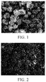
- FIG. 1 is a scanning electron microscopy (SEM) diagram of negative electrode material particles including micron silicon and fluorinated graphite according to Embodiment 1.
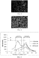
- FIG. 2 , FIG. 3, and FIG. 4 are SEM-EDS diagrams of fluorine element, carbon element, and silicon element of the negative electrode material according to Embodiment 1 respectively.
- FIG. 2 to FIG. 4 illustrate that the surface of micron silicon is evenly coated with a layer of fluorinated graphite material.
- FIG. 5 shows V-dQ/dV curves in a case of delithiating the negative electrode according to Embodiments 1 and 3 and Comparative Embodiment 1, where A represents the strongest peak between 0.2V and 0.35V and B represents the strongest peak between 0.4V and 0.55V
- FIG. 6 shows delithiation curves obtained by discharging the negative electrode under a given lithiation depth according to Embodiments 1 and 3 and Comparative Embodiment 1.
- FIG. 6 illustrates that different B/A values have different delithiation capacities, depending on the controlled lithiation capacity.
- FIG. 7 is a curve of cycling performance after a test of 20 charge-discharge cycles according to Embodiments 1 and 3 and Comparative Embodiment 1. As shown in FIG.
- Comparative Embodiment 1, Embodiment 3 and Comparative Embodiment 1 show that when the ratio B/A is in the range of 1.0-3.0, the discharge capacity retention rate after 20 cycles of the battery can still remain above 95%.
- the battery cycling performance in Embodiments 1 and 3 is significantly better than that in Comparative Embodiment 1. This application significantly improves the battery cycling performance by controlling B/A to 1.0-3.0.
- the test results in Table 2 indicate that silicon oxide (for example, SiO x particles) can also achieve similar effects as micron silicon. That is, when the negative electrode material includes a silicon oxide and a fluorocarbon, the battery cycling performance can be considerably improved by controlling the lithiation depth of the negative electrode and keeping the ratio B/A within 1.0-3.0.
- references to “embodiments”, “some embodiments”, “an embodiment”, “another example”, “example”, “specific example” or “some examples” throughout the specification mean that at least one embodiment or example in this application includes specific features, structures, materials, or characteristics described in the embodiment(s) or example(s). Therefore, descriptions throughout the specification, which make references by using expressions such as “in some embodiments”, “in an embodiment”, “in one embodiment”, “in another example”, “in an example”, “in a specific example”, or “example”, do not necessarily refer to the same embodiment or example in this application.
- specific features, structures, materials, or characteristics herein may be combined in one or more embodiments or examples in any appropriate manner.
Landscapes
- Chemical & Material Sciences (AREA)
- Chemical Kinetics & Catalysis (AREA)
- Electrochemistry (AREA)
- General Chemical & Material Sciences (AREA)
- Engineering & Computer Science (AREA)
- Materials Engineering (AREA)
- Inorganic Chemistry (AREA)
- Manufacturing & Machinery (AREA)
- Nanotechnology (AREA)
- Physics & Mathematics (AREA)
- Composite Materials (AREA)
- Condensed Matter Physics & Semiconductors (AREA)
- General Physics & Mathematics (AREA)
- Crystallography & Structural Chemistry (AREA)
- Battery Electrode And Active Subsutance (AREA)
Abstract
Description
- This application relates to the electrochemical field, and in particular, to a negative electrode material, a negative electrode containing the negative electrode material, and a negative electrode manufacturing method.
- With the rapid development of portable electronic products, communications electronic devices, and the like, the demand for secondary batteries with a high energy density is increasingly urgent. Compared with conventional graphite negative electrode materials, silicon has an extraordinarily high theoretical capacity. Therefore, in recent years, the research on silicon serving as a negative electrode material is explosively growing. Currently, as a negative electrode material, silicon improves the energy density. However, cycling stability of silicon needs to be further improved. A failure of the silicon negative electrode material mainly stems from the following facts: huge volume expansion of silicon after lithiation; and a high reactivity between a silicon surface and an electrolyte. This continuously increases a thickness of a solid electrolyte interphase (SEI) film, continuously consumes reversible lithium, and leads to capacity fading.
- Therefore, it is urgent to develop a negative electrode material that has a high energy density and excellent cycling performance.
- This application discloses a negative electrode material, a negative electrode containing the negative electrode material, and a negative electrode manufacturing method to solve at least one problem in the related art to some extent.
- According to an embodiment of this application, this application discloses a negative electrode material, including: a silicon-containing material, where a ratio B/A of a maximum value B in differentials dQ/dV with respect to 0.4V-0.55V to a maximum value A in differentials dQ/dV with respect to 0.2V-0.35V is approximately 1.0-3.0 when the negative electrode material is electrified in a delithiation direction in a case of charging and discharging a battery that includes a negative electrode made of the negative electrode material and used as a working electrode, metallic lithium used as a counter electrode, and an electrolyte containing a lithium-ion conductive substance, and in a case of plotting a curve of a relationship between a differential dQ/dV and a working electrode potential V, where the differential is obtained by differentiating a charge/discharge capacity Q with respect to the working electrode potential V.
- According to an embodiment of this application, this application further discloses a negative electrode manufacturing method, including: forming a negative electrode containing a negative electrode material; and performing steps of lithiating and delithiating the negative electrode. The negative electrode material includes a silicon-containing material, and the silicon-containing material includes at least one of pure silicon, silicon carbon, a micron silicon alloy, or a silicon oxide. In the steps of lithiating and delithiating, a ratio B/A of a maximum value B in differentials dQ/dV with respect to 0.4V-0.55V to a maximum value A in differentials dQ/dV with respect to 0.2V-0.35V is approximately 1.0-3.0 when the negative electrode material is electrified in a delithiation direction in a case of charging and discharging a battery that includes the negative electrode used as a working electrode, metallic lithium used as a counter electrode, and an electrolyte containing a lithium-ion conductive substance, and in a case of plotting a curve of a relationship between a differential dQ/dV and a working electrode potential V, where the differential is obtained by differentiating a charge/discharge capacity Q with respect to the working electrode potential V
- According to an embodiment of this application, the ratio B/A of the negative electrode material is kept within approximately 1.0-3.0 by controlling a lithiation depth of the negative electrode.
- According to an embodiment of this application, the silicon-containing material includes at least one of pure silicon, silicon carbon, a silicon alloy, or a silicon oxide.
- According to an embodiment of this application, a ratio B/A is approximately 2.0 to 3.0 in a case that the silicon-containing material includes a silicon oxide.
- According to an embodiment of this application, the silicon oxide is a silicon oxide denoted by a general formula SiOx, where 0<x<2.
- According to an embodiment of this application, at least a part of an outer surface of a SiOx particle is coated with carbon.
- According to an embodiment of this application, a median diameter of SiOx particles is D50 greater than 1 µm and less than 10 µm.
- According to an embodiment of this application, a specific surface area of SiOx particles is less than 5 m2/g.
- According to an embodiment of this application, the negative electrode material further includes a fluorocarbon, where the fluorocarbon includes at least one of fluorinated graphite, fluorinated hard carbon, fluorinated soft carbon, fluorinated carbon nanotube, or fluorinated graphene.
- According to an embodiment of this application, based on a total weight of the negative electrode material, a weight percent content of the fluorocarbon is less than or equal to approximately 20%.
- According to an embodiment of this application, the pure silicon includes at least one of a micron particle, a nanoparticle, a nanowire, a nanofilm, or a nanosphere.
- According to an embodiment of this application, this application further discloses a negative electrode containing any negative electrode material described above.
- According to an embodiment of this application, this application further discloses an electrochemical apparatus, including any negative electrode described above.
- According to an embodiment of this application, this application further discloses an electronic apparatus, including any electrochemical apparatus described above.
- Additional aspects and advantages of the embodiments of this application will be described or illustrated in part later herein or expounded through implementation of the embodiments of this application.
- For ease of describing the embodiments of this application, the following outlines the drawings necessary for describing the embodiments of this application or the prior art. Apparently, the drawings outlined below are only some embodiments in this application. Without making any creative efforts, a person skilled in the art can still obtain the drawings of other embodiments according to the structures illustrated in these drawings.
-
FIG. 1 is a scanning electron microscopy (SEM) diagram of negative electrode material particles including micron silicon and fluorinated graphite according to Embodiment 1; -
FIG. 2 is a scanning electron microscopy-energy dispersive spectroscopy (SEM-EDS) diagram of fluorine element in the negative electrode material according to Embodiment 1; -
FIG. 3 is a SEM-EDS diagram of carbon element in the negative electrode material according to Embodiment 1; -
FIG. 4 is a SEM-EDS diagram of silicon element in the negative electrode material according to Embodiment 1; -
FIG. 5 is a V-dQ/dV curve in a case of delithiating a negative electrode according to Embodiment 1,Embodiment 3, and Comparative Embodiment 1; -
FIG. 6 is a delithiation curve according to Embodiment 1,Embodiment 3, and Comparative Embodiment 1; and -
FIG. 7 is a cycling performance curve according to Embodiment 1,Embodiment 3, and Comparative Embodiment 1. - Embodiments of this application will be described in detail below. Throughout the specification of this application, the same or similar components and the components having the same or similar functions are denoted by similar reference numerals. The embodiments described herein with reference to the accompanying drawings are illustrative and graphical in nature, and are intended to enable a basic understanding of this application. The embodiments of this application shall not be construed as a limitation on this application.
- The terms "roughly," "substantially," "substantively", and "approximately" used herein are intended to describe and represent small changes. When used with reference to an event or situation, such terms may denote an example in which the event or situation occurs exactly and an example in which the event or situation occurs very similarly. For example, when used together with a numerical value, the terms may denote a variation range less than or equal to ±10% of the numerical value, such as less than or equal to ±5%, less than or equal to ±4%, less than or equal to ±3%, less than or equal to ±2%, less than or equal to ±1%, less than or equal to ±0.5%, less than or equal to ±0.1%, or less than or equal to ±0.05%. For example, if a difference between two numerical values is less than or equal to ±10% of an average of the numerical values (such as less than or equal to ±5%, less than or equal to ±4%, less than or equal to ±3%, less than or equal to ±2%, less than or equal to ±1%, less than or equal to ±0.5%, less than or equal to ±0.1%, or less than or equal to ±0.05%), the two numerical values may be considered "substantially" the same.
- In addition, an amount, a ratio, or another numerical value is sometimes expressed in a range format herein. Understandably, such a range format is for convenience and brevity, and needs to be flexibly understood to include not only the numerical values explicitly specified in range limits, but also all individual numerical values or sub-ranges covered in the range as if each numerical value and each sub-range are explicitly specified.
- In the description of embodiments and the claims, a list of items referred to by using the terms such as "at least one of", "at least one in", "at least one type of" or other similar terms may mean any combination of the listed items. For example, if items A and B are listed, the phrase "at least one of A or B" means: only A; only B; or, A and B. In another example, if items A, B, and C are listed, the phrase "at least one of A, B, or C" means: only A; only B; only C; A and B (excluding C); A and C (excluding B); B and C (excluding A); or, all of A, B and C. The item A may include a single component or multiple components. The item B may include a single component or multiple components. The item C may include a single component or multiple components.
- In order to explore cycling performance of negative electrode materials including a silicon-containing material, in this application, a battery that includes a negative electrode material including a silicon-containing material used as a working electrode, metallic lithium used as a counter electrode, and an electrolyte containing a lithium-ion conductive substance is charged and discharged, and a curve of a relationship (V-dQ/dV) between a differential dQ/dV and a working electrode potential V is plotted, where the differential is obtained by differentiating a charge/discharge capacity Q with respect to the working electrode potential V. When the negative electrode material is electrified in a delithiation direction, a maximum value in differentials dQ/dV with respect to approximately 0.2V-0.35V is A, and a maximum value in differentials dQ/dV with respect to approximately 0.4V-0.55V is B.
- Research by the inventor of this application shows that by screening silicon-containing materials whose ratio B/A is approximately 1.0-3.0, the cycling performance of the negative electrode materials including the silicon-containing materials can be significantly enhanced.
- The research by the inventor of this application shows that by selectively controlling a lithiation degree of a negative electrode containing the negative electrode material, the ratio B/A is kept within approximately 1.0-3.0, and the cycling performance of the negative electrode material is greatly improved.
- In addition, the research by the inventor of this application shows that by introducing a fluorocarbon into the negative electrode material including a silicon-containing material, the cycling performance of the negative electrode material can be further improved.
- The invention in this application will be described in detail below, but this application is not limited to the following description.
- This application discloses a negative electrode material, a negative electrode containing the negative electrode material, and a negative electrode manufacturing method. In addition, this application further discloses an electrochemical apparatus and an electronic apparatus that each contains the negative electrode material.
- This application discloses a negative electrode material, including a silicon-containing material. A ratio B/A of a maximum value B in differentials dQ/dV with respect to approximately 0.4V-0.55V to a maximum value A in differentials dQ/dV with respect to approximately 0.2V-0.35V is approximately 1.0-3.0 when the negative electrode material is electrified in a delithiation direction in a case of charging and discharging, between 0V and 2V, a battery that includes a negative electrode material used as a working electrode, metallic lithium used as a counter electrode, and an electrolyte containing a lithium-ion conductive substance, and in a case of plotting a V-dQ/dV curve.
- In some embodiments, the ratio B/A may be approximately 1.0 to 1.8, approximately 1.4 to 1.7, or approximately 2.0 to 2.5, for example, may be roughly 1.0, 1.2, 1.4, 1.6, 1.8, 2.0, 2.1, 2.2, 2.3, 2.4, 2.5, 2.6, 2.7, 2.8, 2.9, or 3.0, or may be a range defined by any two of such ratios.
- In some embodiments, the silicon-containing material includes at least one of pure silicon, silicon carbon, a silicon alloy, or a silicon oxide. In some embodiments, the silicon oxide is a silicon oxide denoted by a general formula SiOx, where 0<x<2. In some embodiments, the negative electrode material includes SiOx particles, and a median diameter of the SiOx particles is D50 greater than 1 µm and less than 10 µm. For example, in some embodiments, the median diameter D50 of the SiOx particles may be approximately 2 µm, approximately 3 µm, approximately 4 µm, approximately 5 µm, approximately 6 µm, approximately 7 µm, approximately 8 µm, approximately 9 µm, or approximately 10 µm, or a range defined by any two of such values. In some embodiments, at least a part of an outer surface of a SiOx particle may be coated with carbon. In some embodiments, a specific surface area of the SiOx particles is less than approximately 5 m2/g. For example, in some embodiments, the specific surface area of the SiOx particles is less than approximately 4 m2/g or approximately 2 m2/g or the like.
- In some embodiments, the silicon-containing material includes pure silicon, and the pure silicon may be at least one of a micron particle, an irregular nanoparticle, a nanowire, a nanofilm, or a nanosphere.
- In some embodiments, the silicon-containing material includes a silicon alloy, and the silicon alloy includes at least one of a ferrosilicon alloy, a silicon-aluminum alloy, a silicon-nickel alloy, or a ferro silicon aluminum alloy.
- In some embodiments, the negative electrode material may further include a fluorocarbon, where the fluorocarbon includes at least one of fluorinated graphite, fluorinated hard carbon, fluorinated soft carbon, fluorinated carbon nanotube, or fluorinated graphene. In some embodiments, the fluorocarbon may be on a surface of the silicon-containing material. During a first-charge or lithiation process of the negative electrode containing the negative electrode material, the fluorocarbon reacts in situ around or on the surface of particles of the silicon-containing material to form a graphene-like sheet layer and a lithium fluoride coating layer. The graphene-like sheet layer increases conductivity of the negative electrode, and the lithium fluoride coating layer may be used as an solid electrolyte interphase (SEI) film and may serve a protective function for a surface of a silicon-containing negative electrode active substance particle, thereby further improving the cycling performance of the negative electrode material.
- In some embodiments, based on a total weight of the negative electrode material, a weight percent content of the fluorocarbon is less than or equal to approximately 20%. In some embodiments, based on the total weight of the negative electrode material, the weight percent content of the fluorocarbon is less than or equal to approximately 5%, less than or equal to approximately 10%, less than or equal to approximately 15%, approximately 5% to approximately 10%, approximately 5% to approximately 15%, approximately 10% to approximately 20%, or the like.
- This application discloses a negative electrode, and the negative electrode contains any negative electrode material described above.
- In some embodiments, the negative electrode may further include a bonding agent in addition to a negative electrode material. the bonding agent improves bonding between negative electrode material particles and bonding between the negative electrode material and a current collector. In some embodiments, the bonding agent includes, but is not limited to: polyvinyl alcohol, carboxymethyl cellulose, hydroxypropyl cellulose, diacetyl cellulose, polyvinyl chloride, carboxylated polyvinyl chloride, polyvinyl fluoride, a polymer containing ethylene oxide, polyvinylpyrrolidone, polyurethane, polytetrafluoroethylene, poly (1,1-difluoroethylene), polyethylene, polypropylene, styrene-butadiene rubber, acrylic styrene-butadiene rubber, epoxy resin, and nylon.
- In some embodiments, the negative electrode may further include a conductive agent in addition to a negative electrode material and a bonding agent. The conductive agent includes, but is not limited to, a carbon-based material, a metal-based material, a conductive polymer, or a mixture thereof. In some embodiments, the carbon-based material is selected from natural graphite, artificial graphite, carbon black, acetylene black, Ketjen black, carbon fiber, or any combination thereof. In some embodiments, the metal-based material is selected from metal powder, metal fiber, copper, nickel, aluminum, and silver. In some embodiments, the conductive polymer is a polyphenylene derivative. This application further discloses a negative electrode manufacturing method, including: forming a negative electrode containing a negative electrode material; and performing steps of lithiating and delithiating the negative electrode. The negative electrode material includes a silicon-containing material, and the silicon-containing material includes at least one of pure silicon, silicon carbon, a silicon alloy, or a silicon oxide. In the steps of lithiating and delithiating, a ratio B/A of a maximum value B in differentials dQ/dV with respect to 0.4V-0.55V to a maximum value A in differentials dQ/dV with respect to 0.2V-0.35V is 1.0-3.0 when the negative electrode material is electrified in a delithiation direction in a case of charging and discharging a battery that includes the negative electrode used as a working electrode, metallic lithium used as a counter electrode, and an electrolyte containing a lithium-ion conductive substance, and in a case of plotting a V-dQ/dV curve.
- In some embodiments, silicon-containing negative electrode materials may be screened so that the ratio B/A is approximately 1.0-3.0. The screened negative electrode material with the ratio B/A of approximately 1.0-3.0 is used to manufacture the negative electrode so that the negative electrode has good cycling performance.
- In some embodiments, the ratio B/A may be kept within approximately 1.0-3.0 by controlling a lithiation depth of the negative electrode. By selectively controlling the lithiation depth of the negative electrode, the ratio B/A is still kept within approximately 1.0-3.0 without screening the silicon-containing negative electrode materials, so that the negative electrode has good cycling performance.
- In some embodiments, the ratio B/A may be kept within approximately 1.0-3.0 by both screening the silicon-containing negative electrode materials and controlling the lithiation depth of the negative electrode.
- In some embodiments, the step of forming a negative electrode containing a negative electrode material includes: mixing a silicon-containing material and a fluorocarbon to form a negative electrode material, mixing the negative electrode material, a conductive agent, and a bonding agent at a specific ratio to obtain a negative electrode slurry, and then applying the negative electrode slurry to a negative electrode current collector (such as a copper current collector), and performing baking and calendering to obtain a negative electrode.
- In some embodiments, the controlling the lithiation depth of the negative electrode includes: determining a lithiation capacity Q1 in a 100% state of charge (SOC), selecting an appropriate charging process, and controlling a first-charge capacity to x%Q1 to achieve an x%SOC lithiation depth.
- An embodiment of this application further discloses an electrochemical apparatus including a negative electrode material in this application. The electrochemical apparatus may be any apparatus in which an electrochemical reaction occurs. Specific examples of the apparatus include all kinds of primary batteries, secondary batteries, fuel cells, solar cells, or capacitors. In particular, the electrochemical apparatus is a lithium secondary battery, including a lithium metal secondary battery, a lithium-ion secondary battery, a lithium polymer secondary battery, or a lithium-ion polymer secondary battery. The electrochemical apparatus includes a positive electrode, the negative electrode, and a separator disposed between the positive electrode and the negative electrode.
- In some embodiments, the electrochemical apparatus is a lithium-ion battery. The lithium-ion battery includes a positive electrode containing a positive electrode material, a negative electrode containing a negative electrode material, an electrolyte, and a separator located between the positive electrode and the negative electrode. The negative electrode material is the negative electrode material described above. A positive electrode current collector may be an aluminum foil or a nickel foil, and a negative electrode current collector may be a copper foil or a nickel foil.
- In some embodiments, the positive electrode material may include lithium cobaltate (LiCoO2), a lithium nickel cobalt manganese (NCM) ternary material, lithium ferrous phosphate (LiFePO4), lithium manganate (LiMn2O4), or any combination thereof.
- In some embodiments, the electrochemical apparatus in this application has a separator disposed between the positive electrode and the negative electrode to prevent short circuit. The material and the shape of the separator used in the electrochemical apparatus in this application are not particularly limited, and may be based on any technologies disclosed in the prior art. In some embodiments, the separator includes a polymer or an inorganic substance or the like formed of a material that is stable to the electrolyte.
- The electrochemical apparatus manufactured from the negative electrode material described in this application is applicable to electronic apparatuses in various fields.
- The use of the electrochemical apparatus in this application is not particularly limited, and the electrochemical apparatus may be used for any purpose known in the art. In an embodiment, the electrochemical apparatus in this application is applicable to, but without limitation, a notebook computer, a pen-inputting computer, a mobile computer, an e-book player, a portable phone, a portable fax machine, a portable photocopier, a portable printer, a stereo headset, a video recorder, a liquid crystal display television set, a handheld cleaner, a portable CD player, a mini CD-ROM, a transceiver, an electronic notepad, a calculator, a memory card, a portable voice recorder, a radio, a backup power supply, a motor, a car, a motorcycle, a power-assisted bicycle, a bicycle, a lighting appliance, a toy, a game machine, a watch, an electric tool, a flashlight, a camera, a large household battery, a lithium-ion capacitor, and the like.
- The following describes this application in further detail with reference to embodiments and comparative embodiments. However, to the extent not departing from the essence of this application, this application is not limited to such embodiments.
- 10 grams of micron silicon (whose D50 is approximately 4 µm) and 0.5 gram of fluorinated graphite (that is, a weight percent content of the fluorinated graphite is 4.8%) are ball-mill mixed to form a negative electrode material (
FIG. 1 is a SEM diagram of a negative electrode active substance according to Embodiment 1). The negative electrode material, a conductive agent, and a bonding agent are mixed at a ratio of 8:1:1 representing negative electrode material:conductive agent:bonding agent to obtain a negative electrode slurry, and then the obtained negative electrode slurry is applied to a copper current collector. The copper current collector is baked and calendered to obtain a negative electrode. The manufactured negative electrode is combined with metal lithium serving as a counter electrode, so as to assemble a coin half-cell. The assembled coin half-cell is charged and discharged, and a lithiation depth of the negative electrode is controlled to 25%SOC. A V-dQ/dV curve is plotted. The negative electrode is electrified at a 0.05C rate in a delithiation direction. A ratio B/A of a maximum value B in differentials dQ/dV with respect to 0.4V-0.55V to a maximum value A in differentials dQ/dV with respect to 0.2V-0.35V is 2.14. - Discharging is performed with a 0.05C rate constant current until 5mV, and then discharging is performed with a 50 µA current instead until 5mV, and then discharging is performed with a 10 µA current until 5mV. The discharge capacity at this time serves as a lithiation capacity Q for 100%SOC. The lithiation depth may be controlled in multiple ways. For example, the lithiation depth may be controlled to 25%SOC by a first-charge capacity of 25%Q achieved by lithiating with a 0.05C rate constant current for 5 hours.
- The manufacturing method in
Embodiment 2 is the same as that in Embodiment 1 except that inEmbodiment 2, the lithiation depth of the negative electrode is controlled to 35%SOC and the ratio B/Ais 1.06. - The manufacturing method in
Embodiment 3 is the same as that in Embodiment 1 except that inEmbodiment 3, the lithiation depth of the negative electrode is controlled to 40%SOC and the ratio B/A is 1.74. - The manufacturing method in Embodiment 4 is the same as that in Embodiment 1 except that in Embodiment 4, the lithiation depth of the negative electrode is controlled to 43%SOC and the ratio B/Ais 1.4.
- The manufacturing method in
Embodiment 5 is the same as that in Embodiment 1 except that inEmbodiment 5, the lithiation depth of the negative electrode is controlled to 48%SOC and the ratio B/A is 2.3. - The manufacturing method in Embodiment 6 is the same as that in Embodiment 1 except that in Embodiment 6, the lithiation depth of the negative electrode is controlled to 50%SOC and the ratio B/A is 1.
- The manufacturing method in Embodiment 7 is the same as that in Embodiment 1 except that in Embodiment 7, the lithiation depth of the negative electrode is controlled to 55%SOC and the ratio B/Ais 2.8.
- The manufacturing method in Embodiment 8 is the same as that in Embodiment 1 except that in Embodiment 8, the negative electrode contains no fluorinated graphite, the lithiation depth of the negative electrode is controlled to 55%SOC, and the ratio B/A is 2.7.
- The manufacturing method in Embodiment 9 is the same as that in Embodiment 1 except that in Embodiment 9, the negative electrode contains no fluorinated graphite, the lithiation depth of the negative electrode is controlled to 48%SOC, and the ratio B/A is 2.2.
- The manufacturing method in
Embodiment 10 is the same as that in Embodiment 1 except that inEmbodiment 10, the negative electrode contains no fluorinated graphite, the lithiation depth of the negative electrode is controlled to 25%SOC, and the ratio B/A is 2.0. - 10 grams of SiOx (where 0<x<2, D50 is 6 µm, and a specific surface area is 2m2/g) and 0.5 gram of fluorinated graphite (that is, a weight percent content of the fluorinated graphite is 4.8%) are ball-mill mixed to form a negative electrode material. The negative electrode material, a conductive agent, and a bonding agent are mixed at a ratio of 8:1:1 representing negative electrode material:conductive agent:bonding agent to obtain a negative electrode slurry, and then the obtained negative electrode slurry is applied to a copper current collector. The copper current collector is baked and calendered to obtain a negative electrode. The manufactured negative electrode is combined with metal lithium serving as a counter electrode, so as to assemble a coin half-cell. The assembled coin half-cell is charged and discharged, and a lithiation depth of the negative electrode is controlled to 50%SOC. A V-dQ/dV curve is plotted. The negative electrode is electrified at a 0.05C rate in a delithiation direction. A ratio B/A of a maximum value B in differentials dQ/dV with respect to 0.4V-0.55V to a maximum value A in differentials dQ/dV with respect to 0.2V-0.35V is 2.
- The manufacturing method in Embodiment 12 is the same as that in Embodiment 11 except that in Embodiment 12, the lithiation depth of the negative electrode is controlled to 65%SOC and the ratio B/A is 1.29.
- The manufacturing method in Comparative Embodiment 1 is the same as that in Embodiment 1 except that in Comparative Embodiment 1, the lithiation depth of the negative electrode is controlled to 73%SOC and the ratio B/A is 0.84.
- The manufacturing method in
Comparative Embodiment 2 is the same as that in Embodiment 1 except that inComparative Embodiment 2, the lithiation depth of the negative electrode is controlled to 100%SOC and the ratio B/A is 24. - The manufacturing method in
Comparative Embodiment 3 is the same as that in Embodiment 1 except that inComparative Embodiment 3, the lithiation depth of the negative electrode is controlled to 10%SOC and the ratio B/A is 0.4. - 10 grams of micron silicon (whose D50 is approximately 4 µm) are used as a negative electrode material. The negative electrode material, a conductive agent, and a bonding agent are mixed at a ratio of 8:1:1 representing negative electrode material:conductive agent:bonding agent to obtain a negative electrode slurry, and then the obtained negative electrode slurry is applied to a copper current collector. The copper current collector is baked and calendered to obtain a negative electrode. The manufactured negative electrode is combined with metal lithium serving as a counter electrode, so as to assemble a coin half-cell. The assembled coin half-cell is discharged with a 0.05C rate constant current until 5mV, and then discharged with a 50 µA current instead until 5mV, and then discharged with a 10 µA current until 5mV. The discharge capacity at this time is 90% of the capacity existent after the same discharging process is completed in Comparative Embodiment 2 (in which the negative electrode contains fluorinated graphite), denoted by 90%SOC. A V-dQ/dV curve is plotted. The negative electrode is electrified at a 0.05C rate in a delithiation direction. A ratio B/A of a maximum value B in differentials dQ/dV with respect to 0.4V-0.55V to a maximum value A in differentials dQ/dV with respect to 0.2V-0.35V is 10.
- The manufacturing method in
Comparative Embodiment 5 is the same as that in - Embodiment 11 except that in
Comparative Embodiment 5, the lithiation depth of the negative electrode is controlled to 85%SOC and the ratio B/A is 0.60. - The manufacturing method in Comparative Embodiment 6 is the same as that in Embodiment 11 except that in Comparative Embodiment 6, the lithiation depth of the negative electrode is controlled to 98%SOC and the ratio B/A is 0.56.
- Discharging is performed in Embodiments 1 to 12 and Comparative Embodiments 1 to 6 in which a lithium depth is given, so as to obtain a corresponding voltage VI, then discharging is performed with a 0.05C rate constant current until a corresponding voltage VI, and then discharging is performed with a 50 µA current instead until the voltage VI. Finally, the discharging is performed with a 10 µA current until the voltage VI, and the discharging is completed. Charging is performed with a 0.05C rate constant current until 1.2V, so that one charge-discharge cycle is completed. 20 charge-discharge cycles are performed in the foregoing way to test the cycling performance of the lithium-ion battery. Table 1 shows test results in Embodiments 1 to 10 and Comparative Embodiments 1 to 4. Table 2 shows test results in Embodiments 11 and 12 and Comparative Embodiments 5 and 6.
Table 1 Sample B/A Content of fluorinated graphite Lithiation depth SOC Delithiation capacity (mAh/g) Capacity retention rate after 20 cycles Embodiment 1 2.14 4.8% 25% 837 96.0 % Embodiment 2 1.06 4.8% 35% 1204 101.0 % Embodiment 3 1.74 4.8% 40% 1399 107.2% Embodiment 4 1.4 4.8% 43% 1506 102.0 % Embodiment 5 2.3 4.8% 48% 1658 90.0% Embodiment 6 1 4.8% 50% 1768 89.0% Embodiment 7 2.8 4.8% 55% 1830 86.0% Embodiment 8 2.7 0% 55% 1805 80.0% Embodiment 9 2.2 0% 48% 1637 86.0 % Embodiment 10 2.0 0% 25% 806 91.0% Comparative Embodiment 1 0.84 4.8% 73% 2535 55.6% Comparative Embodiment 224 4.8% 100% 3478 46.0% Comparative Embodiment 30.4 4.8% 10% 319 76.0% Comparative Embodiment 4 10 0% 90% 3186 39.0% Table 2 Sample B/A Content of fluorinated graphite Lithiation depth SOC Delithiation capacity (mAh/g) Capacity retention rate after 30 cycles Embodiment 11 2 4.8% 50% 541 150% Embodiment 12 1.29 4.8% 65% 934 110% Comparative Embodiment 50.6 4.8% 85% 1340 100% Comparative Embodiment 6 0.56 4.8% 98% 1547 92.8% - As can be learned from the test results in Table 1, when the negative electrode material includes micron silicon and fluorinated graphite, the battery cycling performance can be considerably improved by controlling the lithiation depth of the negative electrode and keeping the ratio B/A within 1.0-3.0.
-
FIG. 1 is a scanning electron microscopy (SEM) diagram of negative electrode material particles including micron silicon and fluorinated graphite according to Embodiment 1.FIG. 2 ,FIG. 3, and FIG. 4 are SEM-EDS diagrams of fluorine element, carbon element, and silicon element of the negative electrode material according to Embodiment 1 respectively.FIG. 2 to FIG. 4 illustrate that the surface of micron silicon is evenly coated with a layer of fluorinated graphite material. -
FIG. 5 shows V-dQ/dV curves in a case of delithiating the negative electrode according toEmbodiments 1 and 3 and Comparative Embodiment 1, where A represents the strongest peak between 0.2V and 0.35V and B represents the strongest peak between 0.4V and 0.55VFIG. 6 shows delithiation curves obtained by discharging the negative electrode under a given lithiation depth according toEmbodiments 1 and 3 and Comparative Embodiment 1.FIG. 6 illustrates that different B/A values have different delithiation capacities, depending on the controlled lithiation capacity.FIG. 7 is a curve of cycling performance after a test of 20 charge-discharge cycles according toEmbodiments 1 and 3 and Comparative Embodiment 1. As shown inFIG. 7 , Comparative Embodiment 1,Embodiment 3 and Comparative Embodiment 1 show that when the ratio B/A is in the range of 1.0-3.0, the discharge capacity retention rate after 20 cycles of the battery can still remain above 95%. The battery cycling performance inEmbodiments 1 and 3 is significantly better than that in Comparative Embodiment 1. This application significantly improves the battery cycling performance by controlling B/A to 1.0-3.0. - The test results in Table 2 indicate that silicon oxide (for example, SiOx particles) can also achieve similar effects as micron silicon. That is, when the negative electrode material includes a silicon oxide and a fluorocarbon, the battery cycling performance can be considerably improved by controlling the lithiation depth of the negative electrode and keeping the ratio B/A within 1.0-3.0.
- References to "embodiments", "some embodiments", "an embodiment", "another example", "example", "specific example" or "some examples" throughout the specification mean that at least one embodiment or example in this application includes specific features, structures, materials, or characteristics described in the embodiment(s) or example(s). Therefore, descriptions throughout the specification, which make references by using expressions such as "in some embodiments", "in an embodiment", "in one embodiment", "in another example", "in an example", "in a specific example", or "example", do not necessarily refer to the same embodiment or example in this application. In addition, specific features, structures, materials, or characteristics herein may be combined in one or more embodiments or examples in any appropriate manner.
- Although illustrative embodiments have been demonstrated and described above, a person skilled in the art understands that the above embodiments shall not be construed as a limitation on this application, and changes, replacements, and modifications may be made to the embodiments without departing from the spirit, principles, and scope of this application.
Claims (15)
- A negative electrode material, comprising a silicon-containing material, wherein:
a ratio B/A of a maximum value B in differentials dQ/dV with respect to 0.4V-0.55V to a maximum value A in differentials dQ/dV with respect to 0.2V-0.35V is 1.0-3.0 when the negative electrode material is electrified in a delithiation direction in a case of charging and discharging a battery that comprises a negative electrode made of the negative electrode material and used as a working electrode, metallic lithium used as a counter electrode, and an electrolyte containing a lithium-ion conductive substance, and in a case of plotting a curve of a relationship between a differential dQ/dV and a working electrode potential V, wherein the differential is obtained by differentiating a charge/discharge capacity Q with respect to the working electrode potential V. - The negative electrode material according to claim 1, wherein the silicon-containing material comprises at least one of pure silicon, silicon carbon, a silicon alloy, or a silicon oxide.
- The negative electrode material according to claim 2, wherein the silicon oxide is a silicon oxide denoted by a general formula SiOx, wherein 0<x<2.
- The negative electrode material according to claim 3, wherein at least a part of an outer surface of a SiOx particle is coated with carbon.
- The negative electrode material according to claim 3, wherein a median diameter of SiOx particles is D50 greater than 1 µm and less than 10 µm.
- The negative electrode material according to claim 3, wherein a specific surface area of SiOx particles is less than 5 m2/g.
- The negative electrode material according to claim 1, further comprising a fluorocarbon, wherein the fluorocarbon is at least one of fluorinated graphite, fluorinated hard carbon, fluorinated soft carbon, fluorinated carbon nanotube, or fluorinated graphene.
- The negative electrode material according to claim 7, wherein based on a total weight of the negative electrode material, a weight percent content of the fluorocarbon is less than or equal to 20%.
- The negative electrode material according to claim 2, wherein the pure silicon comprises at least one of a micron particle, a nanoparticle, a nanowire, a nanofilm, or a nanosphere.
- A negative electrode, comprising the negative electrode material according to any one of claims 1 to 9.
- An electrochemical apparatus, comprising the negative electrode according to claim 10.
- An electronic apparatus, comprising the electrochemical apparatus according to claim 11.
- A negative electrode manufacturing method, comprising:forming a negative electrode containing a negative electrode material; andperforming steps of lithiating and delithiating the negative electrode, whereinthe negative electrode material comprises a silicon-containing material, and the silicon-containing material comprises at least one of pure silicon, silicon carbon, a silicon alloy, or a silicon oxide; andin the steps of lithiating and delithiating, a ratio B/A of a maximum value B in differentials dQ/dV with respect to 0.4V-0.55V to a maximum value A in differentials dQ/dV with respect to 0.2V-0.35V is 1.0-3.0 when the negative electrode material is electrified in a delithiation direction in a case of charging and discharging a battery that comprises the negative electrode used as a working electrode, metallic lithium used as a counter electrode, and an electrolyte containing a lithium-ion conductive substance, and in a case of plotting a curve of a relationship between a differential dQ/dV and a working electrode potential V, wherein the differential is obtained by differentiating a charge/discharge capacity Q with respect to the working electrode potential V.
- The manufacturing method according to claim 13, wherein the ratio B/A of the negative electrode material is kept within 1.0-3.0 by controlling a lithiation depth of the negative electrode.
- The manufacturing method according to claim 13, wherein the negative electrode material further comprises a fluorocarbon, the fluorocarbon is at least one of fluorinated graphite, fluorinated hard carbon, fluorinated soft carbon, fluorinated carbon nanotube, or fluorinated graphene; and, based on a total weight of the negative electrode material, a weight percent content of the fluorocarbon is less than or equal to 20%.
Applications Claiming Priority (2)
| Application Number | Priority Date | Filing Date | Title |
|---|---|---|---|
| CN201911039028.5A CN110828812A (en) | 2019-10-29 | 2019-10-29 | Negative electrode material, negative electrode including the same, and preparation method of negative electrode |
| PCT/CN2020/072938 WO2021082291A1 (en) | 2019-10-29 | 2020-01-19 | Negative electrode material, negative electrode comprising same, and negative electrode preparation method |
Publications (2)
| Publication Number | Publication Date |
|---|---|
| EP4040538A1 true EP4040538A1 (en) | 2022-08-10 |
| EP4040538A4 EP4040538A4 (en) | 2024-07-31 |
Family
ID=69551103
Family Applications (1)
| Application Number | Title | Priority Date | Filing Date |
|---|---|---|---|
| EP20883580.1A Pending EP4040538A4 (en) | 2019-10-29 | 2020-01-19 | NEGATIVE ELECTRODE MATERIAL, NEGATIVE ELECTRODE INCLUDING SAME, AND METHOD FOR PREPARING NEGATIVE ELECTRODE |
Country Status (3)
| Country | Link |
|---|---|
| EP (1) | EP4040538A4 (en) |
| CN (1) | CN110828812A (en) |
| WO (1) | WO2021082291A1 (en) |
Families Citing this family (9)
| Publication number | Priority date | Publication date | Assignee | Title |
|---|---|---|---|---|
| CN111554903A (en) * | 2020-05-12 | 2020-08-18 | 宁德新能源科技有限公司 | Negative electrode material, negative electrode sheet, electrochemical device, and electronic device |
| CN111554902B (en) * | 2020-05-12 | 2022-06-24 | 宁德新能源科技有限公司 | Negative electrode material, negative electrode sheet, electrochemical device, and electronic device |
| WO2021226841A1 (en) * | 2020-05-12 | 2021-11-18 | 宁德新能源科技有限公司 | Negative electrode material, negative electrode sheet, electrochemical device and electronic device |
| EP4231382A4 (en) * | 2020-09-11 | 2025-05-21 | Shanghai Shanshan Tech Co., Ltd. | SILICON-BASED LITHIUM STORAGE MATERIAL AND PREPARATION METHOD THEREOF |
| CN112687873B (en) * | 2020-12-23 | 2021-12-07 | 湖南永盛新材料股份有限公司 | Preparation method of high-specific-energy lithium battery |
| CN116724419A (en) * | 2021-09-26 | 2023-09-08 | 宁德时代新能源科技股份有限公司 | Silicon carbon negative electrode materials, negative electrode sheets, secondary batteries, battery modules, battery packs and electrical devices |
| CN115241412B (en) * | 2022-06-17 | 2025-09-02 | 珠海冠宇电池股份有限公司 | A pole piece and a battery |
| CN116609367A (en) * | 2023-07-19 | 2023-08-18 | 天津力神电池股份有限公司 | Selection method and application of target silicon anode material |
| CN117133911A (en) * | 2023-10-26 | 2023-11-28 | 中创新航科技集团股份有限公司 | Anode active material and lithium-ion battery using same |
Family Cites Families (8)
| Publication number | Priority date | Publication date | Assignee | Title |
|---|---|---|---|---|
| JP5682955B2 (en) * | 2010-08-04 | 2015-03-11 | Necエナジーデバイス株式会社 | Lithium secondary battery control system and lithium secondary battery state detection method |
| JP5975024B2 (en) * | 2011-05-27 | 2016-08-23 | 日本電気株式会社 | Method for doping and dedoping lithium to negative electrode and method for producing negative electrode for lithium secondary battery |
| JP6179404B2 (en) * | 2011-09-21 | 2017-08-16 | 日本電気株式会社 | Manufacturing method of secondary battery |
| JP6466635B2 (en) * | 2013-06-14 | 2019-02-06 | 信越化学工業株式会社 | Method for producing negative electrode for nonaqueous electrolyte secondary battery and method for producing nonaqueous electrolyte secondary battery |
| CN104953087B (en) * | 2014-03-26 | 2018-07-06 | 联想(北京)有限公司 | A kind of lithium battery and its cathode, battery core, cathode voltage monitoring method |
| US10147950B2 (en) * | 2015-08-28 | 2018-12-04 | Group 14 Technologies, Inc. | Materials with extremely durable intercalation of lithium and manufacturing methods thereof |
| JP2018147772A (en) * | 2017-03-07 | 2018-09-20 | 日立化成株式会社 | Lithium ion secondary battery negative electrode material and lithium ion secondary battery |
| CN109167031B (en) * | 2018-08-21 | 2020-08-11 | 浙江大学 | Nano silicon-carbon composite material and preparation method and application thereof |
-
2019
- 2019-10-29 CN CN201911039028.5A patent/CN110828812A/en active Pending
-
2020
- 2020-01-19 WO PCT/CN2020/072938 patent/WO2021082291A1/en not_active Ceased
- 2020-01-19 EP EP20883580.1A patent/EP4040538A4/en active Pending
Also Published As
| Publication number | Publication date |
|---|---|
| CN110828812A (en) | 2020-02-21 |
| EP4040538A4 (en) | 2024-07-31 |
| US20220216465A1 (en) | 2022-07-07 |
| WO2021082291A1 (en) | 2021-05-06 |
Similar Documents
| Publication | Publication Date | Title |
|---|---|---|
| US12456736B2 (en) | Sodium metal battery and electrochemical apparatus | |
| US20220216471A1 (en) | Lithium supplementing material and positive electrode containing same | |
| EP4123760A1 (en) | Negative electrode active material, electrochemical device using same, and electronic apparatus | |
| CN105308776B (en) | Cathode active material, its preparation method and include its lithium secondary battery | |
| CN110828812A (en) | Negative electrode material, negative electrode including the same, and preparation method of negative electrode | |
| WO2021008429A1 (en) | Secondary battery, and battery module, battery pack and device related thereto | |
| CN114373889A (en) | Negative electrode for secondary battery and secondary battery including the same | |
| EP4679519A2 (en) | Electrochemical device and electronic device containing same | |
| CN115295755A (en) | Electrochemical device and electronic device including the same | |
| CN112310346A (en) | Negative plate for polymer lithium ion battery with ultrahigh energy density | |
| CN114824168B (en) | Lithium supplementing agent for positive electrode of lithium ion battery, lithium supplementing method, positive electrode plate, lithium supplementing slurry and battery | |
| EP4283706B1 (en) | Negative electrode plate and application thereof | |
| EP4456229A1 (en) | Separator, electrochemical device, and electronic device | |
| CN113574700A (en) | Method for manufacturing negative electrode of secondary battery | |
| CN101243565B (en) | Electrochemical device having high capacity and method for manufacturing the same | |
| EP4611068A1 (en) | Battery and electric device | |
| CN115986053A (en) | Negative electrode sheet, secondary battery, and power consumption device | |
| CN116264268B (en) | A negative electrode for a secondary battery, a method for manufacturing the negative electrode, and a lithium secondary battery including the negative electrode. | |
| CN110931754A (en) | A kind of negative electrode material, its preparation method, negative electrode pole piece and electrochemical device | |
| Singh et al. | Evaluation and screening of Si-based anode materials in commercial Li-ion cells for electric vehicle applications | |
| US12633529B2 (en) | Negative electrode material, negative electrode containing negative electrode material, and negative electrode manufacturing method | |
| CN113206213A (en) | Silicon-based composite electrode and preparation method and application thereof | |
| JP7764621B2 (en) | Negative electrode sheet, secondary battery, battery module, battery pack, and power consumption device | |
| CN113921914B (en) | Electrolyte solution, and electrochemical device and electronic device using same | |
| JP2000040510A (en) | Non-aqueous electrolyte secondary battery |
Legal Events
| Date | Code | Title | Description |
|---|---|---|---|
| STAA | Information on the status of an ep patent application or granted ep patent |
Free format text: STATUS: THE INTERNATIONAL PUBLICATION HAS BEEN MADE |
|
| PUAI | Public reference made under article 153(3) epc to a published international application that has entered the european phase |
Free format text: ORIGINAL CODE: 0009012 |
|
| STAA | Information on the status of an ep patent application or granted ep patent |
Free format text: STATUS: REQUEST FOR EXAMINATION WAS MADE |
|
| 17P | Request for examination filed |
Effective date: 20220506 |
|
| AK | Designated contracting states |
Kind code of ref document: A1 Designated state(s): AL AT BE BG CH CY CZ DE DK EE ES FI FR GB GR HR HU IE IS IT LI LT LU LV MC MK MT NL NO PL PT RO RS SE SI SK SM TR |
|
| DAV | Request for validation of the european patent (deleted) | ||
| DAX | Request for extension of the european patent (deleted) | ||
| REG | Reference to a national code |
Ref country code: DE Ref legal event code: R079 Free format text: PREVIOUS MAIN CLASS: H01M0004380000 Ipc: H01M0004134000 |
|
| A4 | Supplementary search report drawn up and despatched |
Effective date: 20240627 |
|
| RIC1 | Information provided on ipc code assigned before grant |
Ipc: H01M 10/0525 20100101ALI20240621BHEP Ipc: H01M 4/62 20060101ALI20240621BHEP Ipc: H01M 4/587 20100101ALI20240621BHEP Ipc: H01M 4/48 20100101ALI20240621BHEP Ipc: H01M 4/38 20060101ALI20240621BHEP Ipc: H01M 4/133 20100101ALI20240621BHEP Ipc: H01M 4/134 20100101AFI20240621BHEP |