EP4040413A1 - Corrugated bug screen - Google Patents
Corrugated bug screen Download PDFInfo
- Publication number
- EP4040413A1 EP4040413A1 EP22154848.0A EP22154848A EP4040413A1 EP 4040413 A1 EP4040413 A1 EP 4040413A1 EP 22154848 A EP22154848 A EP 22154848A EP 4040413 A1 EP4040413 A1 EP 4040413A1
- Authority
- EP
- European Patent Office
- Prior art keywords
- louvers
- corrugated
- chamber
- space
- bug
- Prior art date
- Legal status (The legal status is an assumption and is not a legal conclusion. Google has not performed a legal analysis and makes no representation as to the accuracy of the status listed.)
- Granted
Links
Images



Classifications
-
- G—PHYSICS
- G08—SIGNALLING
- G08B—SIGNALLING SYSTEMS, e.g. PERSONAL CALLING SYSTEMS; ORDER TELEGRAPHS; ALARM SYSTEMS
- G08B17/00—Fire alarms; Alarms responsive to explosion
- G08B17/10—Actuation by presence of smoke or gases, e.g. automatic alarm devices for analysing flowing fluid materials by the use of optical means
- G08B17/11—Actuation by presence of smoke or gases, e.g. automatic alarm devices for analysing flowing fluid materials by the use of optical means using an ionisation chamber for detecting smoke or gas
- G08B17/113—Constructional details
-
- A—HUMAN NECESSITIES
- A01—AGRICULTURE; FORESTRY; ANIMAL HUSBANDRY; HUNTING; TRAPPING; FISHING
- A01M—CATCHING, TRAPPING OR SCARING OF ANIMALS; APPARATUS FOR THE DESTRUCTION OF NOXIOUS ANIMALS OR NOXIOUS PLANTS
- A01M29/00—Scaring or repelling devices, e.g. bird-scaring apparatus
- A01M29/30—Scaring or repelling devices, e.g. bird-scaring apparatus preventing or obstructing access or passage, e.g. by means of barriers, spikes, cords, obstacles or sprinkled water
- A01M29/34—Scaring or repelling devices, e.g. bird-scaring apparatus preventing or obstructing access or passage, e.g. by means of barriers, spikes, cords, obstacles or sprinkled water specially adapted for insects
Definitions
- the present disclosure relates to smoke detectors and, in particular, to a corrugated bug screen for smoke detector applications.
- the mesh bug screen is formed into a uniform, cylindrical shape to circumferentially surround a uniform, cylindrical air flow structure (e.g., a detection chamber) of a smoke detector.
- a uniform, cylindrical air flow structure e.g., a detection chamber
- a detection chamber assembly of a smoke detector includes upper and lower covers, louvers and a corrugated bug screen.
- the louvers are arranged with the upper and lower covers to define a chamber bound between the upper and lower covers and the louvers.
- the louvers include a first pair of louvers defining a first space therebetween to permit fluidic ingress to the chamber and a second pair of louvers defining a second space therebetween to permit fluidic ingress to the chamber.
- the second space is wider than the first space.
- the corrugated bug screen includes a body disposed about the louvers and a mesh corrugation feature coupled to the body at the second space to permit fluidic ingress to the chamber at the second space and to inhibit bug ingress to the chamber at the second space.
- the louvers may include multiple second pairs of louvers, each respectively defining second spaces therebetween and the corrugated bug screen may include multiple mesh corrugation features. Each respective mesh corrugation feature may be coupled at corresponding ones of the multiple second spaces.
- the mesh corrugation feature may include a tip and first and second tapered sidewalls extending from the tip to the body.
- the mesh corrugation feature may permit fluidic ingress to the chamber in a first direction through the tip and in second and third directions through the first and second tapered sidewalls, respectively.
- the mesh-corrugation feature may include a columnar lattice structure at the tip and a row-columnar lattice structure at the first and second tapered sidewalls.
- the mesh corrugation feature may extend inwardly toward the chamber.
- the mesh corrugation feature may extend outwardly from the chamber.
- a detection chamber assembly of a smoke detector includes upper and lower covers, louvers and a corrugated bug screen.
- the louvers are arranged with the upper and lower covers to define a chamber bound between the upper and lower covers and the louvers.
- the louvers include a first pair of louvers defining a first space therebetween to permit fluidic ingress to the chamber and a second pair of louvers defining a second space therebetween to permit fluidic ingress to the chamber.
- the second space is wider than the first space.
- the corrugated bug screen is supported on the second pair of louvers at the second space to permit fluidic ingress to the chamber and to inhibit bug ingress to the chamber.
- the louvers may include multiple second pairs of louvers, each respectively defining second spaces therebetween, and each second space including one corrugated bug screen.
- the mesh corrugation bug screen feature may be supported in slots defined in each of the second pair of louvers.
- the corrugated bug screen may include a curved body.
- the corrugated bug screen may permit fluidic ingress to the chamber in multiple directions normal to corresponding sections of the curved body.
- the corrugated bug screen may include a row-columnar lattice structure.
- the corrugated bug screen may extend inwardly toward the chamber.
- the corrugated bug screen may extend outwardly from the chamber.
- a smoke detector includes a housing defining an interior in which a detection chamber assembly is operably disposed.
- the detection chamber assembly includes upper and lower covers, louvers and a corrugated bug screen.
- the louvers are arranged with the upper and lower covers to define a chamber bound between the upper and lower covers and the louvers.
- the louvers include a first pair of louvers defining a first space therebetween to permit fluidic ingress to the chamber and a second pair of louvers defining a second space therebetween to permit fluid ingress to the chamber.
- the second space is wider than the first space.
- the corrugated bug screen is disposed at the second space to permit fluidic ingress to the chamber and to inhibit bug ingress to the chamber.
- the corrugated bug screen may include a body disposed about the louvers and a mesh corrugation feature coupled to the body at the second space and extending inwardly toward the chamber.
- the corrugated bug screen may include a body disposed about the louvers and a mesh corrugation feature coupled to the body at the second space and extending outwardly from the chamber while remaining within the interior of the external structure.
- the corrugated bug screen may be supported on the second pair of louvers at the second space and extends inwardly toward the chamber.
- the corrugated bug screen may be supported on the second pair of louvers at the second space and extends outwardly from the chamber while remaining within the interior of the external structure.
- a detection chamber assembly incorporating a corrugated bug screen and a smoke detector incorporating the detection chamber assembly are provided.
- the bug screen is formed into a corrugated shape with indentations and other geometric features designed to trap air and improve smoke entry.
- the corrugated shape can at least partially take the form of a star or be a mostly cylindrical shape with areas of corrugation that fit into or around open areas of an optical cover of the detection chamber assembly. It can also take the form of a partial mesh structure that covers large openings of the optical cover (e.g., where the corrugation may extend into the interior of the optical cover, between louvers).
- a detection chamber assembly 101 includes an upper cover 110 (commonly referred to as an optical cover) and a lower cover 120. As shown, detection chamber assembly 101 or either the upper cover 110 itself or the lower cover 120 itself may include a plurality of louvers 130 (the louvers 130 may be attached to or formed together with the upper cover 110 or the lower cover 120).
- the upper and lower covers 110 and 120 can be, but are not required to be, annular or substantially circular. For purposes of clarity and brevity, the following description will relate to the cases in which the upper and lower covers 110 and 120 are substantially circular.
- the louvers 130 may be arranged circumferentially about the respective peripheries 111,121 of the upper cover 110 and the lower cover 120 to define a chamber 140 between the upper cover 110 and the lower cover 120 (bound circumferentially within the louvers 130).
- the louvers 130 may each be provided as static elements with somewhat complex geometries and include first pairs of louvers 131 and at least one or more second pair of louvers 132. It should be appreciated that each respective first pair of louvers 131 may be separated from one another by a defined first space 1310, and each respective second pair of louvers 132 may be separated from one another by a defined second space 1320.
- the second space 1320 may be greater (i.e., wider than) the first space 1310 in certain instances.
- the louvers 130 include multiple first pairs of louvers 131 and two pairs of second louvers 132, although it is envisioned that the detection chamber assembly 101 described herein may include any number of first pairs of louvers 131 and any number of second pairs of louvers 132.
- the multiple first pairs of louvers 131 may be arranged to define multiple first spaces 1310 therebetween (i.e., one first space 1310 between each respective pair of first louvers 131). Each of the multiple first spaces 1310 may be configured and disposed to permit fluidic ingress to the chamber 140.
- the two pairs of second louvers 132 may be arranged to define two second spaces 1320 therebetween (i.e., one second space 1320 between each respective pair of second louvers 132). Each of the second spaces 1320 may be wider than any of the first spaces 1310 and may be configured and disposed to permit fluidic ingress to the chamber 140.
- the detection chamber assembly 101 further includes at least one corrugated bug screen 150 (also 510, see FIG. 5 ). It will be appreciated that the corrugated bug screen 150, 501 described herein may be provided in multiple configurations. A first configuration of the corrugated bug screen 150 is shown in FIGS. 1-4 , and a second configuration of the corrugated bug screen 510 is shown in FIGS. 5-6 .
- the first embodiment of the corrugated bug screen 150 includes a body 151 that is disposed about the louvers 130 and a mesh corrugation feature 152.
- the mesh corrugation feature 152 can be provided as one, two or more than two mesh corrugation features 152. It is to be understood that the following description will relate to the cases in which two mesh corrugation features are provided in correspondence with the two second spaces 1320.
- Each mesh corrugation feature 152 may be coupled to the body 151 at a corresponding one of the two second spaces 1320 to permit fluidic ingress to the chamber 140 and to inhibit bug ingress to the chamber 140.
- the body 151 of the corrugated bug screen 150 may be substantially circular and configured to tightly fit about or around the louvers 130 (e.g., between the upper cover 110 and the lower cover 120).
- the mesh corrugation features 152 can be respectively disposed in positional correspondence with each corresponding one of the second spaces 1320.
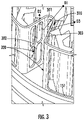
- each of the mesh corrugation features 152 can include a tip 301 and first and second tapered sidewalls 302 and 303 extending in opposite directions from the tip 301 to the body 151. As shown in FIG. 3 , the tip 301 and the corners between the body 151 and the first and second tapered sidewalls 302 and 303 can be curved in certain instances. In accordance with embodiments, each of the mesh corrugation features 152 permits fluidic ingress to the chamber 140 in a first direction D1 through the tip 301 and in second and third directions D2 and D3 through the first and second tapered sidewalls 302 and 303, respectively.
- each of the mesh-corrugation features 152 can include a columnar lattice structure 310 at the tip 301 (i.e., a column of openings separated by a horizontal crossbar) and a row-columnar lattice structure 320 at the first and second tapered sidewalls 302 and 303 (i.e., rows and columns of openings separated by crisscrossing vertical and horizontal crossbars).
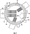
- each of the mesh corrugation features 152 can extend radially inwardly toward the chamber 140 or radially outwardly from the chamber 140.
- the detection chamber assembly 101 may include one or more of a second configuration of the corrugated bug screen 510 (i.e., between second louvers 132).
- the detection chamber assembly 101 illustrated in FIGS. 5 and 6 may be viewed as the same or similar to the detection chamber assembly 101 described above (e.g., the detection chamber assembly 101 may include one or more pair(s) of second louvers 132, etc.).
- the second configuration of the corrugated bug screen 510 (shown in FIGS. 5 and 6 ) may be supported at opposite ends thereof on each of the second pair of louvers 132 at each of the second spaces 1320.
- the second configuration of the corrugated bug screen 510 may be designed to permit fluidic ingress to the chamber 140 and to inhibit bug ingress to the chamber 140.
- each corrugated bug screen 510 can include a curved body 512 and be designed to permit fluidic ingress to the chamber 140 in multiple directions D1-D5 normal to corresponding sections of the curved body 512.
- each corrugated bug screen 510 can include a row-columnar lattice structure 520 (i.e., rows and columns of openings separated by crisscrossing vertical and horizontal crossbars) along the curved body 512.
- each corrugated bug screen 510 can extend radially inwardly toward the chamber 140 or radially outwardly from the chamber 140.
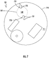
- a smoke detector 701 which includes a housing 710 defining an interior 711 and a detection chamber assembly 101, such as the detection chamber assembly 101 described above, which, as described above, includes a corrugated bug screen 150, 510. It should be appreciated that either of the configurations of the corrugated bug screen 150, 510 described above may be incorporated within the smoke detector 701 (although the corrugated bug screen is labeled 730 in FIG. 7 ).
- the corrugated bug screen 730 may include mesh corrugation features 731 (labeled 152 in FIGS. 1-4 ) at each of the second spaces to permit fluidic ingress to the chamber 140 and to inhibit bug ingress to the chamber 140.
- the corrugated bug screen 730 can include a body disposed about the louvers 130 with the mesh corrugation features 731 coupled to the body at the second spaces and either extending inwardly toward the chamber 140 or outwardly from the chamber 140 while remaining within the interior 711 of the housing 710.
- the corrugated bug screen 730 (labeled 510 in FIGS. 5 and 6 ) can be supported on the second pairs of louvers at the second spaces and can either extend inwardly toward the chamber 140 or outwardly from the chamber 140 while remaining within the interior 711 of the external structure 710.
Landscapes
- Life Sciences & Earth Sciences (AREA)
- Pest Control & Pesticides (AREA)
- Insects & Arthropods (AREA)
- Emergency Management (AREA)
- Physics & Mathematics (AREA)
- General Physics & Mathematics (AREA)
- Chemical & Material Sciences (AREA)
- Business, Economics & Management (AREA)
- Analytical Chemistry (AREA)
- Birds (AREA)
- Engineering & Computer Science (AREA)
- Wood Science & Technology (AREA)
- Zoology (AREA)
- Environmental Sciences (AREA)
- Fire-Detection Mechanisms (AREA)
Abstract
Description
- The present disclosure relates to smoke detectors and, in particular, to a corrugated bug screen for smoke detector applications.
- In photo-electric type smoke detectors, it is typically important to prevent insects from entering a smoke or detection chamber and creating a false signal. This is often done with a mesh screen that surrounds the air flow openings of the smoke or detection chamber. Conventional mesh bug screens are designed in such a way that they inhibit air flow behavior and in turn limit smoke entry (which may affect the ability of the smoke detector to accurately detect the presence of smoke).
- Typically, the mesh bug screen is formed into a uniform, cylindrical shape to circumferentially surround a uniform, cylindrical air flow structure (e.g., a detection chamber) of a smoke detector.
- According to a first aspect, a detection chamber assembly of a smoke detector is provided. The detection chamber assembly includes upper and lower covers, louvers and a corrugated bug screen. The louvers are arranged with the upper and lower covers to define a chamber bound between the upper and lower covers and the louvers. The louvers include a first pair of louvers defining a first space therebetween to permit fluidic ingress to the chamber and a second pair of louvers defining a second space therebetween to permit fluidic ingress to the chamber. The second space is wider than the first space. The corrugated bug screen includes a body disposed about the louvers and a mesh corrugation feature coupled to the body at the second space to permit fluidic ingress to the chamber at the second space and to inhibit bug ingress to the chamber at the second space.
- The louvers may include multiple second pairs of louvers, each respectively defining second spaces therebetween and the corrugated bug screen may include multiple mesh corrugation features. Each respective mesh corrugation feature may be coupled at corresponding ones of the multiple second spaces.
- The mesh corrugation feature may include a tip and first and second tapered sidewalls extending from the tip to the body.
- The mesh corrugation feature may permit fluidic ingress to the chamber in a first direction through the tip and in second and third directions through the first and second tapered sidewalls, respectively.
- The mesh-corrugation feature may include a columnar lattice structure at the tip and a row-columnar lattice structure at the first and second tapered sidewalls.
- The mesh corrugation feature may extend inwardly toward the chamber.
- The mesh corrugation feature may extend outwardly from the chamber.
- According to another aspect a detection chamber assembly of a smoke detector is provided and includes upper and lower covers, louvers and a corrugated bug screen. The louvers are arranged with the upper and lower covers to define a chamber bound between the upper and lower covers and the louvers. The louvers include a first pair of louvers defining a first space therebetween to permit fluidic ingress to the chamber and a second pair of louvers defining a second space therebetween to permit fluidic ingress to the chamber. The second space is wider than the first space. The corrugated bug screen is supported on the second pair of louvers at the second space to permit fluidic ingress to the chamber and to inhibit bug ingress to the chamber.
- The louvers may include multiple second pairs of louvers, each respectively defining second spaces therebetween, and each second space including one corrugated bug screen.
- The mesh corrugation bug screen feature may be supported in slots defined in each of the second pair of louvers.
- The corrugated bug screen may include a curved body.
- The corrugated bug screen may permit fluidic ingress to the chamber in multiple directions normal to corresponding sections of the curved body.
- The corrugated bug screen may include a row-columnar lattice structure.
- The corrugated bug screen may extend inwardly toward the chamber.
- The corrugated bug screen may extend outwardly from the chamber.
- According to another aspect , a smoke detector is provided and includes a housing defining an interior in which a detection chamber assembly is operably disposed. The detection chamber assembly includes upper and lower covers, louvers and a corrugated bug screen. The louvers are arranged with the upper and lower covers to define a chamber bound between the upper and lower covers and the louvers. The louvers include a first pair of louvers defining a first space therebetween to permit fluidic ingress to the chamber and a second pair of louvers defining a second space therebetween to permit fluid ingress to the chamber. The second space is wider than the first space. The corrugated bug screen is disposed at the second space to permit fluidic ingress to the chamber and to inhibit bug ingress to the chamber.
- The corrugated bug screen may include a body disposed about the louvers and a mesh corrugation feature coupled to the body at the second space and extending inwardly toward the chamber.
- The corrugated bug screen may include a body disposed about the louvers and a mesh corrugation feature coupled to the body at the second space and extending outwardly from the chamber while remaining within the interior of the external structure.
- The corrugated bug screen may be supported on the second pair of louvers at the second space and extends inwardly toward the chamber.
- The corrugated bug screen may be supported on the second pair of louvers at the second space and extends outwardly from the chamber while remaining within the interior of the external structure.
- Additional features and advantages are realized through the techniques of the present disclosure. Other embodiments and aspects of the disclosure are described in detail herein and are considered a part of the claimed technical concept. For a better understanding of the disclosure with the advantages and the features, refer to the description and to the drawings.
- Certain exemplary embodiments will now be described in greater detail by way of example only and with reference to the accompanying drawings in which:
-
FIG. 1 is a perspective view of an exemplary detection chamber assembly for a photo-electric smoke detector; -
FIG. 2 is an exploded perspective view of a portion of the exemplary detection chamber ofFIG. 1 , illustrating an exemplary corrugated bug screen separated from an exemplary upper cover; -
FIG. 3 is an enlarged perspective view of a portion of the exemplary corrugated bug screen and a portion of the exemplary upper cover ofFIG. 2 ; -
FIG. 4 is a top-down view illustrating the exemplary detection chamber assembly ofFIG. 1 with an exemplary corrugated bug screen; -
FIG. 5 is an enlarged perspective view of a portion of the exemplary detection chamber assembly ofFIG. 1 with two exemplary corrugated bug screens, each respectively disposed between a pair of louvers; -
FIG. 6 is a top-down view illustrating exemplary corrugated bug screens disposed between pairs of louvers; and -
FIG. 7 is a top-down view of a portion of an exemplary smoke detector with a portion of the housing removed to illustrate an exemplary location for the detection chamber assembly ofFIG. 1 . - As will be described below, a detection chamber assembly incorporating a corrugated bug screen and a smoke detector incorporating the detection chamber assembly are provided. The bug screen is formed into a corrugated shape with indentations and other geometric features designed to trap air and improve smoke entry. The corrugated shape can at least partially take the form of a star or be a mostly cylindrical shape with areas of corrugation that fit into or around open areas of an optical cover of the detection chamber assembly. It can also take the form of a partial mesh structure that covers large openings of the optical cover (e.g., where the corrugation may extend into the interior of the optical cover, between louvers).
- With reference to
FIGS. 1 and2 , adetection chamber assembly 101 is provided and includes an upper cover 110 (commonly referred to as an optical cover) and alower cover 120. As shown,detection chamber assembly 101 or either theupper cover 110 itself or thelower cover 120 itself may include a plurality of louvers 130 (thelouvers 130 may be attached to or formed together with theupper cover 110 or the lower cover 120). The upper andlower covers lower covers - As shown in
FIG. 2 , thelouvers 130 may be arranged circumferentially about the respective peripheries 111,121 of theupper cover 110 and thelower cover 120 to define achamber 140 between theupper cover 110 and the lower cover 120 (bound circumferentially within the louvers 130). Thelouvers 130 may each be provided as static elements with somewhat complex geometries and include first pairs oflouvers 131 and at least one or more second pair oflouvers 132. It should be appreciated that each respective first pair oflouvers 131 may be separated from one another by a definedfirst space 1310, and each respective second pair oflouvers 132 may be separated from one another by a definedsecond space 1320. As will be described below, thesecond space 1320 may be greater (i.e., wider than) thefirst space 1310 in certain instances. For purposes of clarity and brevity, the following description will relate to the cases in which thelouvers 130 include multiple first pairs oflouvers 131 and two pairs ofsecond louvers 132, although it is envisioned that thedetection chamber assembly 101 described herein may include any number of first pairs oflouvers 131 and any number of second pairs oflouvers 132. - As shown in
FIG. 2 , the multiple first pairs oflouvers 131 may be arranged to define multiplefirst spaces 1310 therebetween (i.e., onefirst space 1310 between each respective pair of first louvers 131). Each of the multiplefirst spaces 1310 may be configured and disposed to permit fluidic ingress to thechamber 140. The two pairs ofsecond louvers 132 may be arranged to define twosecond spaces 1320 therebetween (i.e., onesecond space 1320 between each respective pair of second louvers 132). Each of thesecond spaces 1320 may be wider than any of thefirst spaces 1310 and may be configured and disposed to permit fluidic ingress to thechamber 140. - The
detection chamber assembly 101 further includes at least one corrugated bug screen 150 (also 510, seeFIG. 5 ). It will be appreciated that thecorrugated bug screen 150, 501 described herein may be provided in multiple configurations. A first configuration of thecorrugated bug screen 150 is shown inFIGS. 1-4 , and a second configuration of thecorrugated bug screen 510 is shown inFIGS. 5-6 . - The first embodiment of the
corrugated bug screen 150 includes abody 151 that is disposed about thelouvers 130 and amesh corrugation feature 152. Themesh corrugation feature 152 can be provided as one, two or more than two mesh corrugation features 152. It is to be understood that the following description will relate to the cases in which two mesh corrugation features are provided in correspondence with the twosecond spaces 1320. Eachmesh corrugation feature 152 may be coupled to thebody 151 at a corresponding one of the twosecond spaces 1320 to permit fluidic ingress to thechamber 140 and to inhibit bug ingress to thechamber 140. - As shown in
FIGS. 1-4 , depicting the first configuration of thecorrugated bug screen 150, thebody 151 of thecorrugated bug screen 150 may be substantially circular and configured to tightly fit about or around the louvers 130 (e.g., between theupper cover 110 and the lower cover 120). In these or other cases, the mesh corrugation features 152 can be respectively disposed in positional correspondence with each corresponding one of thesecond spaces 1320. - With continued reference to
FIGS. 1 and2 and with additional reference toFIG. 3 , each of the mesh corrugation features 152 can include atip 301 and first and secondtapered sidewalls tip 301 to thebody 151. As shown inFIG. 3 , thetip 301 and the corners between thebody 151 and the first and secondtapered sidewalls chamber 140 in a first direction D1 through thetip 301 and in second and third directions D2 and D3 through the first and secondtapered sidewalls columnar lattice structure 310 at the tip 301 (i.e., a column of openings separated by a horizontal crossbar) and a row-columnar lattice structure 320 at the first and secondtapered sidewalls 302 and 303 (i.e., rows and columns of openings separated by crisscrossing vertical and horizontal crossbars). - With reference to
FIG. 4 and in accordance with alternative embodiments, each of the mesh corrugation features 152 can extend radially inwardly toward thechamber 140 or radially outwardly from thechamber 140. - With reference to
FIG. 5 , thedetection chamber assembly 101 may include one or more of a second configuration of the corrugated bug screen 510 (i.e., between second louvers 132). Thedetection chamber assembly 101 illustrated inFIGS. 5 and 6 may be viewed as the same or similar to thedetection chamber assembly 101 described above (e.g., thedetection chamber assembly 101 may include one or more pair(s) ofsecond louvers 132, etc.). The second configuration of the corrugated bug screen 510 (shown inFIGS. 5 and 6 ) may be supported at opposite ends thereof on each of the second pair oflouvers 132 at each of thesecond spaces 1320. As with the first configuration of the corrugated bug screen 150 (shown inFIGS. 1-4 ), the second configuration of thecorrugated bug screen 510 may be designed to permit fluidic ingress to thechamber 140 and to inhibit bug ingress to thechamber 140. - As shown in
FIG. 5 , when referring to the second configuration of thecorrugated bug screen 510, the opposite ends of thecorrugated bug screen 510 can be supported inslots 511 defined in each of thesecond louvers 132. Also, as shown inFIG. 5 , eachcorrugated bug screen 510 can include acurved body 512 and be designed to permit fluidic ingress to thechamber 140 in multiple directions D1-D5 normal to corresponding sections of thecurved body 512. In accordance with further embodiments, eachcorrugated bug screen 510 can include a row-columnar lattice structure 520 (i.e., rows and columns of openings separated by crisscrossing vertical and horizontal crossbars) along thecurved body 512. - With reference to
FIG. 6 and in accordance with alternative embodiments, eachcorrugated bug screen 510 can extend radially inwardly toward thechamber 140 or radially outwardly from thechamber 140. - With reference to
FIG. 7 , asmoke detector 701 is provided, which includes ahousing 710 defining an interior 711 and adetection chamber assembly 101, such as thedetection chamber assembly 101 described above, which, as described above, includes acorrugated bug screen corrugated bug screen FIG. 7 ). - As described above and shown in
FIGS. 1-4 , thecorrugated bug screen 730 may include mesh corrugation features 731 (labeled 152 inFIGS. 1-4 ) at each of the second spaces to permit fluidic ingress to thechamber 140 and to inhibit bug ingress to thechamber 140. Thecorrugated bug screen 730 can include a body disposed about thelouvers 130 with the mesh corrugation features 731 coupled to the body at the second spaces and either extending inwardly toward thechamber 140 or outwardly from thechamber 140 while remaining within theinterior 711 of thehousing 710. Alternatively, as described above and shown inFIGS. 5 and 6 , the corrugated bug screen 730 (labeled 510 inFIGS. 5 and 6 ) can be supported on the second pairs of louvers at the second spaces and can either extend inwardly toward thechamber 140 or outwardly from thechamber 140 while remaining within theinterior 711 of theexternal structure 710. - Technical effects and benefits of the present disclosure are the provision of a smoke detector with improved smoke entry and an enhanced ability to detection conditions of various fires in a surrounding environment. Improved fluidic flows will allow for easier qualification testing at regulatory agencies and for easier requalification of production samples.
- The description of the present invention has been presented for purposes of illustration and description, but is not intended to be exhaustive or limited to the technical concepts in the form disclosed. Many modifications and variations will be apparent to those of ordinary skill in the art without departing from the scope of the invention as defined in the appended claims. The embodiments were chosen and described in order to best explain the principles of the invention and the practical application, and to enable others of ordinary skill in the art to understand the invention for various embodiments with various modifications as are suited to the particular use contemplated.
- While the preferred embodiments to the invention have been described, it will be understood that those skilled in the art, both now and in the future, may make various improvements and enhancements which fall within the scope of the claims which follow. These claims should be construed to maintain the proper protection for the invention first described.
- The following clauses recite features of the invention which may or may not presently be claimed, but which may serve as basis for amendments and/or one or more divisional applications:
- 1. A detection chamber assembly of a smoke detector, the detection chamber assembly comprising: upper and lower covers; louvers arranged with the upper and lower covers to define a chamber bound between the upper and lower covers and the louvers, the louvers comprising: a first pair of louvers defining a first space therebetween to permit fluidic ingress to the chamber, and a second pair of louvers defining a second space therebetween to permit fluidic ingress to the chamber, the second space being wider than the first space; and a corrugated bug screen comprising a body disposed about the louvers and a mesh corrugation feature coupled to the body at the second space to permit fluidic ingress to the chamber at the second space and to inhibit bug ingress to the chamber at the second space.
- 2. The detection chamber assembly according to clause 1, wherein: the louvers comprise multiple second pairs of louvers, each respectively defining second spaces therebetween, and the corrugated bug screen comprises multiple mesh corrugation features, each respective mesh corrugation feature coupled at corresponding ones of the multiple second spaces.
- 3. The detection chamber assembly according to clause 1, wherein the mesh corrugation feature comprises a tip and first and second tapered sidewalls extending from the tip to the body.
- 4. The detection chamber assembly according to clause 3, wherein the mesh corrugation feature permits fluidic ingress to the chamber in a first direction through the tip and in second and third directions through the first and second tapered sidewalls, respectively.
- 5. The detection chamber assembly according to clause 3, wherein the mesh-corrugation feature comprises: a columnar lattice structure at the tip; and a row-columnar lattice structure at the first and second tapered sidewalls.
- 6. The detection chamber assembly according to clause 1, wherein the mesh corrugation feature extends inwardly toward the chamber.
- 7. The detection chamber assembly according to clause 1, wherein the mesh corrugation feature extends outwardly from the chamber.
- 8. A detection chamber assembly of a smoke detector, the detection chamber assembly comprising: an upper cover; a lower cover; louvers arranged with the upper and lower covers to define a chamber bound between the upper and lower covers and the louvers, the louvers comprising: a first pair of louvers defining a first space therebetween to permit fluidic ingress to the chamber, and a second pair of louvers defining a second space therebetween to permit fluidic ingress to the chamber, the second space being wider than the first space; and a corrugated bug screen supported on the second pair of louvers at the second space to permit fluidic ingress to the chamber and to inhibit bug ingress to the chamber.
- 9. The detection chamber assembly according to clause 8, wherein: the louvers comprise multiple second pairs of louvers, each respectively defining second spaces therebetween, each second space comprising one corrugated bug screen.
- 10. The detection chamber assembly according to clause 8, wherein the mesh corrugation bug screen feature is supported in slots defined in each of the second pair of louvers.
- 11. The detection chamber assembly according to clause 8, wherein the corrugated bug screen comprises a curved body.
- 12. The detection chamber assembly according to clause 11, wherein the corrugated bug screen permits fluidic ingress to the chamber in multiple directions normal to corresponding sections of the curved body.
- 13. The detection chamber assembly according to clause 11, wherein the corrugated bug screen comprises a row-columnar lattice structure.
- 14. The detection chamber assembly according to clause 8, wherein the corrugated bug screen extends inwardly toward the chamber.
- 15. The detection chamber assembly according to clause 8, wherein the corrugated bug screen extends outwardly from the chamber.
- 16. A smoke detector comprising: a housing defining an interior in which a detection chamber assembly is operably disposed, the detection chamber assembly comprising: upper and lower covers; louvers arranged with the upper and lower covers to define a chamber bound between the upper and lower covers and the louvers, the louvers comprising: a first pair of louvers defining a first space therebetween to permit fluidic ingress to the chamber, and a second pair of louvers defining a second space therebetween to permit fluid ingress to the chamber, the second space being wider than the first space; and a corrugated bug screen disposed at the second space to permit fluidic ingress to the chamber and to inhibit bug ingress to the chamber.
- 17. The smoke detector according to clause 16, wherein the corrugated bug screen comprises: a body disposed about the louvers; and a mesh corrugation feature coupled to the body at the second space and extending inwardly toward the chamber.
- 18. The smoke detector according to clause 16, wherein the corrugated bug screen comprises: a body disposed about the louvers; and a mesh corrugation feature coupled to the body at the second space and extending outwardly from the chamber while remaining within the interior of the external structure.
- 19. The smoke detector according to clause 16, wherein the corrugated bug screen is supported on the second pair of louvers at the second space and extends inwardly toward the chamber.
- 20. The smoke detector according to clause 16, wherein the corrugated bug screen is supported on the second pair of louvers at the second space and extends outwardly from the chamber while remaining within the interior of the external structure.
Claims (15)
- A detection chamber assembly (101) of a smoke detector (701), the detection chamber assembly comprising:upper (110) and lower (120) covers;louvers (130) arranged with the upper (110) and lower (120) covers to define a chamber (140) bound between the upper (110) and lower (120) covers and the louvers (130), the louvers comprising:a first pair of louvers (131) defining a first space (1310) therebetween to permit fluidic ingress to the chamber (140), anda second pair of louvers (132) defining a second space (1320) therebetween to permit fluidic ingress to the chamber (140), the second space (1320) being wider than the first space (1310); anda corrugated bug screen (150; 152) to permit fluidic ingress to the chamber (140) and to inhibit bug ingress to the chamber (140).
- The detection chamber assembly according to claim 1, wherein the corrugated bug screen (150) comprises a body (151) disposed about the louvers and a mesh corrugation feature (152) coupled to the body at the second space (1320), and wherein the fluidic ingress is at the second space (1320) and the bug ingress is at the second space (1320).
- The detection chamber assembly according to claim 2, wherein:the louvers comprise multiple second pairs of louvers (132), each respectively defining second spaces (1320) therebetween, andthe corrugated bug screen (150) comprises multiple mesh corrugation features (152), each respective mesh corrugation feature coupled at corresponding ones of the multiple second spaces (1320).
- The detection chamber assembly according to claim 2 or 3, wherein the mesh corrugation feature (152) comprises a tip (301) and first (302) and second (303) tapered sidewalls extending from the tip (301) to the body (151).
- The detection chamber assembly according to claim 2, 3 or 4, wherein:the mesh corrugation feature (152) permits fluidic ingress to the chamber (140) in a first direction through the tip (301) and in second and third directions through the first (302) and second (303) tapered sidewalls, respectively, and/orthe mesh-corrugation feature (152) comprises a columnar lattice structure (310) at the tip (301), and a row-columnar lattice structure (320) at the first (302) and second (303) tapered sidewalls.
- The detection chamber assembly according to any of claims 2 to 5, wherein the mesh corrugation feature (152) extends inwardly toward the chamber (140) or wherein the mesh corrugation feature (152) extends outwardly from the chamber (140).
- The detection chamber assembly according to claim 1, wherein the corrugated bug screen (510) is supported on the second pair of louvers (132) at the second space (1320).
- The detection chamber assembly according to claim 7, wherein:
the louvers (130) comprise multiple second pairs of louvers (132), each respectively defining second spaces (1320) therebetween, each second space comprising one corrugated bug screen (510). - The detection chamber assembly according to claim 7 or 8, wherein the corrugated bug screen (510) is supported in slots (511) defined in each of the second pair of louvers (132) and/or the corrugated bug screen (510) comprises a curved body (512).
- The detection chamber assembly according to claim 7, 8, or 9, wherein the corrugated bug screen (510) permits fluidic ingress to the chamber (140) in multiple directions normal to corresponding sections of the curved body (512) and/or the corrugated bug screen (510) comprises a row-columnar lattice structure (520).
- The detection chamber assembly according to any of claims 7 to 10, wherein the corrugated bug screen (510) extends inwardly toward the chamber (140) or wherein the corrugated bug screen (510) extends outwardly from the chamber (140).
- A smoke detector (701) comprising:
a housing (710) defining an interior (711) in which a detection chamber assembly (101) according to claim 1 is operably disposed wherein the corrugated bug screen (150; 510) is disposed at the second space. - The smoke detector according to claim 12, wherein the corrugated bug screen (150) comprises:a body (151) disposed about the louvers (130); anda mesh corrugation feature (152) coupled to the body at the second space (1320) and extending inwardly toward the chamber (140).
- The smoke detector according to claim 12, wherein the corrugated bug screen (150) comprises:a body (151) disposed about the louvers (130); anda mesh corrugation feature (152) coupled to the body at the second space (1320) and extending outwardly from the chamber (140) while remaining within the interior (711) of the external structure (710).
- The smoke detector according to claim 12, wherein:the corrugated bug screen (510) is supported on the second pair of louvers (132) at the second space (1320) and extends inwardly toward the chamber (140), orthe corrugated bug screen (510) is supported on the second pair of louvers (132) at the second space (1320) and extends outwardly from the chamber (140) while remaining within the interior (711) of the external structure (710).
Applications Claiming Priority (1)
| Application Number | Priority Date | Filing Date | Title |
|---|---|---|---|
| US202163145809P | 2021-02-04 | 2021-02-04 |
Publications (2)
| Publication Number | Publication Date |
|---|---|
| EP4040413A1 true EP4040413A1 (en) | 2022-08-10 |
| EP4040413B1 EP4040413B1 (en) | 2025-10-01 |
Family
ID=80225766
Family Applications (1)
| Application Number | Title | Priority Date | Filing Date |
|---|---|---|---|
| EP22154848.0A Active EP4040413B1 (en) | 2021-02-04 | 2022-02-02 | Corrugated bug screen |
Country Status (4)
| Country | Link |
|---|---|
| US (1) | US12051312B2 (en) |
| EP (1) | EP4040413B1 (en) |
| CA (1) | CA3146651A1 (en) |
| ES (1) | ES3050583T3 (en) |
Families Citing this family (2)
| Publication number | Priority date | Publication date | Assignee | Title |
|---|---|---|---|---|
| US11849716B2 (en) * | 2022-01-17 | 2023-12-26 | Honeywell International Inc. | Insect guard for an aspirated smoke, gas, or air quality monitoring systems and devices |
| US20260060236A1 (en) * | 2024-08-28 | 2026-03-05 | David Schuelke | Rodent-blocking vent cap |
Citations (3)
| Publication number | Priority date | Publication date | Assignee | Title |
|---|---|---|---|---|
| EP0569712A1 (en) * | 1992-04-25 | 1993-11-18 | Nohmi Bosai Ltd. | Fire detector |
| EP1049059A2 (en) * | 1999-04-30 | 2000-11-02 | Nittan Company, Limited | Fire detector |
| GB2359354A (en) * | 1999-11-01 | 2001-08-22 | Hochiki Co | Smoke detector and insect screen |
Family Cites Families (26)
| Publication number | Priority date | Publication date | Assignee | Title |
|---|---|---|---|---|
| US3561604A (en) | 1968-01-26 | 1971-02-09 | Caterpillar Mitsubishi Ltd | Filter element |
| JPS605416U (en) | 1983-06-24 | 1985-01-16 | ミドリ安全株式会社 | Air cleaner filter |
| US4672217A (en) * | 1985-04-05 | 1987-06-09 | General Signal Corporation | Easily cleaned photoelectric smoke detector |
| GB2270157B (en) * | 1992-08-28 | 1996-07-24 | Hochiki Co | Light scattering type smoke detector |
| US5400014A (en) * | 1993-07-12 | 1995-03-21 | Detection Systems, Inc. | Smoke detector with dark chamber |
| GB2309080B (en) * | 1993-09-07 | 1997-10-22 | Hochiki Co | Light scattering type smoke sensor |
| US6099608A (en) | 1998-07-30 | 2000-08-08 | 3M Innovative Properties Company | Rotating filtration cartridge and blower for HVAC applications |
| US6057774A (en) * | 1999-01-21 | 2000-05-02 | Brk Brands, Inc. | Smoke alarm with anti-dust screen |
| US6876305B2 (en) | 1999-12-08 | 2005-04-05 | Gentex Corporation | Compact particle sensor |
| US6911144B2 (en) | 2000-12-15 | 2005-06-28 | Bha Group Holdings, Inc. | Filter cartridge with strap and method |
| US6778091B2 (en) * | 2001-01-09 | 2004-08-17 | Qualey, Iii James R. | Smoke chamber |
| TWI235965B (en) * | 2001-04-24 | 2005-07-11 | Matsushita Electric Works Ltd | Fire detector unit |
| JP2006267128A (en) | 2006-06-26 | 2006-10-05 | Hochiki Corp | smoke detector |
| KR100981235B1 (en) | 2009-04-15 | 2010-09-10 | 신정철 | Filter bag and dust collector with same |
| KR101098326B1 (en) | 2009-07-10 | 2011-12-26 | 주식회사 세원하이텍 | fire detector |
| KR101275822B1 (en) | 2010-10-13 | 2013-06-18 | 주식회사 지앤씨 | Manufacture method of bag cage of filter-bag for dust collector |
| US20160023375A1 (en) | 2013-05-17 | 2016-01-28 | Core Cast, Llc | Slip mixture for 3d printed molds and 3d printing ceramic material |
| US9824564B2 (en) * | 2015-12-14 | 2017-11-21 | Honeywell International Inc. | Aspirated smoke detector with improved optical chamber |
| US10512875B2 (en) | 2016-01-22 | 2019-12-24 | Bha Altair, Llc | Filter and filter media having a fiber blend |
| KR101772822B1 (en) | 2016-09-26 | 2017-08-29 | 이병권 | Photo type detector with Double bulkhead structure |
| WO2019142797A1 (en) * | 2018-01-17 | 2019-07-25 | パナソニックIpマネジメント株式会社 | Smoke detector |
| CN208298360U (en) | 2018-03-30 | 2018-12-28 | 宁波锦春智能科技有限公司 | A kind of fire hazard aerosol fog detecting alarm labyrinth for improving detection accuracy |
| CA3099040A1 (en) | 2018-05-09 | 2019-11-14 | Carrier Corporation | Smoke chamber for multiwave multiangle smoke detector |
| MX2021000604A (en) | 2018-07-18 | 2021-07-15 | Poly6 Tech Inc | Articles and methods of manufacture. |
| US11069224B1 (en) * | 2020-07-10 | 2021-07-20 | Everday Techology Co., Ltd. | Smoke detector and chamber |
| US11359941B1 (en) * | 2021-05-14 | 2022-06-14 | SimpliSafe, Inc. | Smoke detector housing and surface mount |
-
2022
- 2022-01-25 CA CA3146651A patent/CA3146651A1/en active Pending
- 2022-02-02 EP EP22154848.0A patent/EP4040413B1/en active Active
- 2022-02-02 ES ES22154848T patent/ES3050583T3/en active Active
- 2022-02-04 US US17/665,082 patent/US12051312B2/en active Active
Patent Citations (3)
| Publication number | Priority date | Publication date | Assignee | Title |
|---|---|---|---|---|
| EP0569712A1 (en) * | 1992-04-25 | 1993-11-18 | Nohmi Bosai Ltd. | Fire detector |
| EP1049059A2 (en) * | 1999-04-30 | 2000-11-02 | Nittan Company, Limited | Fire detector |
| GB2359354A (en) * | 1999-11-01 | 2001-08-22 | Hochiki Co | Smoke detector and insect screen |
Also Published As
| Publication number | Publication date |
|---|---|
| ES3050583T3 (en) | 2025-12-22 |
| EP4040413B1 (en) | 2025-10-01 |
| CA3146651A1 (en) | 2022-08-04 |
| US12051312B2 (en) | 2024-07-30 |
| US20220246010A1 (en) | 2022-08-04 |
Similar Documents
| Publication | Publication Date | Title |
|---|---|---|
| US12051312B2 (en) | Corrugated bug screen | |
| US10537760B2 (en) | Flame-guard filter composed of a number of layer sequences, and arrangements of flame-guard filters and their use | |
| JP6350934B2 (en) | Combined fire detector | |
| EP4213122B1 (en) | Insect guard for an aspirated smoke, gas, or air quality monitoring systems and devices | |
| EP3671680A1 (en) | Fire or smoke alarm | |
| KR102052327B1 (en) | High pressure resistant filter | |
| JP6392094B2 (en) | Photoelectric smoke detector | |
| CN108564759B (en) | Smoke labyrinth hood | |
| JP2017004284A (en) | Fire sensor | |
| JP5154528B2 (en) | Photoelectric smoke detector | |
| JP2009098062A (en) | Pressure sensor | |
| RU2589480C2 (en) | Fuse flashback | |
| JP5075671B2 (en) | Smoke detector | |
| CN210377769U (en) | Prevent alert new-type labyrinth structure and photoelectric smoke detector of wrong report | |
| KR102681722B1 (en) | CID filter for secondary battery and secondary battery | |
| WO2024213723A1 (en) | Improved vent and vent casing | |
| EP2395489A2 (en) | Smoke alarm device | |
| DE3016530C2 (en) | ||
| US20120037624A1 (en) | Electronic enclosure including a flame arrestor having a mechanical check valve | |
| CN114294638A (en) | Improved fluid separation modular frame | |
| BE1027445B1 (en) | Sensor or detector device | |
| RU2815920C2 (en) | Explosion-proof housing with reinforcing frame | |
| WO2026028072A1 (en) | Containment apparatus for a sensor | |
| KR20220028797A (en) | Flame arrester | |
| CN210777051U (en) | Smoke sensor |
Legal Events
| Date | Code | Title | Description |
|---|---|---|---|
| PUAI | Public reference made under article 153(3) epc to a published international application that has entered the european phase |
Free format text: ORIGINAL CODE: 0009012 |
|
| STAA | Information on the status of an ep patent application or granted ep patent |
Free format text: STATUS: THE APPLICATION HAS BEEN PUBLISHED |
|
| AK | Designated contracting states |
Kind code of ref document: A1 Designated state(s): AL AT BE BG CH CY CZ DE DK EE ES FI FR GB GR HR HU IE IS IT LI LT LU LV MC MK MT NL NO PL PT RO RS SE SI SK SM TR |
|
| STAA | Information on the status of an ep patent application or granted ep patent |
Free format text: STATUS: REQUEST FOR EXAMINATION WAS MADE |
|
| 17P | Request for examination filed |
Effective date: 20230210 |
|
| RBV | Designated contracting states (corrected) |
Designated state(s): AL AT BE BG CH CY CZ DE DK EE ES FI FR GB GR HR HU IE IS IT LI LT LU LV MC MK MT NL NO PL PT RO RS SE SI SK SM TR |
|
| P01 | Opt-out of the competence of the unified patent court (upc) registered |
Effective date: 20230527 |
|
| STAA | Information on the status of an ep patent application or granted ep patent |
Free format text: STATUS: EXAMINATION IS IN PROGRESS |
|
| 17Q | First examination report despatched |
Effective date: 20250207 |
|
| GRAP | Despatch of communication of intention to grant a patent |
Free format text: ORIGINAL CODE: EPIDOSNIGR1 |
|
| STAA | Information on the status of an ep patent application or granted ep patent |
Free format text: STATUS: GRANT OF PATENT IS INTENDED |
|
| INTG | Intention to grant announced |
Effective date: 20250429 |
|
| GRAS | Grant fee paid |
Free format text: ORIGINAL CODE: EPIDOSNIGR3 |
|
| GRAA | (expected) grant |
Free format text: ORIGINAL CODE: 0009210 |
|
| STAA | Information on the status of an ep patent application or granted ep patent |
Free format text: STATUS: THE PATENT HAS BEEN GRANTED |
|
| AK | Designated contracting states |
Kind code of ref document: B1 Designated state(s): AL AT BE BG CH CY CZ DE DK EE ES FI FR GB GR HR HU IE IS IT LI LT LU LV MC MK MT NL NO PL PT RO RS SE SI SK SM TR |
|
| REG | Reference to a national code |
Ref country code: GB Ref legal event code: FG4D Ref country code: CH Ref legal event code: F10 Free format text: ST27 STATUS EVENT CODE: U-0-0-F10-F00 (AS PROVIDED BY THE NATIONAL OFFICE) Effective date: 20251001 |
|
| REG | Reference to a national code |
Ref country code: DE Ref legal event code: R096 Ref document number: 602022022113 Country of ref document: DE |
|
| REG | Reference to a national code |
Ref country code: IE Ref legal event code: FG4D |
|
| REG | Reference to a national code |
Ref country code: ES Ref legal event code: FG2A Ref document number: 3050583 Country of ref document: ES Kind code of ref document: T3 Effective date: 20251222 |
|
| REG | Reference to a national code |
Ref country code: NL Ref legal event code: MP Effective date: 20251001 |
|
| REG | Reference to a national code |
Ref country code: AT Ref legal event code: MK05 Ref document number: 1843362 Country of ref document: AT Kind code of ref document: T Effective date: 20251001 |
|
| PG25 | Lapsed in a contracting state [announced via postgrant information from national office to epo] |
Ref country code: NL Free format text: LAPSE BECAUSE OF FAILURE TO SUBMIT A TRANSLATION OF THE DESCRIPTION OR TO PAY THE FEE WITHIN THE PRESCRIBED TIME-LIMIT Effective date: 20251001 |
|
| PGFP | Annual fee paid to national office [announced via postgrant information from national office to epo] |
Ref country code: GB Payment date: 20260121 Year of fee payment: 5 |
|
| PGFP | Annual fee paid to national office [announced via postgrant information from national office to epo] |
Ref country code: ES Payment date: 20260302 Year of fee payment: 5 |
|
| REG | Reference to a national code |
Ref country code: LT Ref legal event code: MG9D |
|
| PG25 | Lapsed in a contracting state [announced via postgrant information from national office to epo] |
Ref country code: NO Free format text: LAPSE BECAUSE OF FAILURE TO SUBMIT A TRANSLATION OF THE DESCRIPTION OR TO PAY THE FEE WITHIN THE PRESCRIBED TIME-LIMIT Effective date: 20260101 |
|
| PG25 | Lapsed in a contracting state [announced via postgrant information from national office to epo] |
Ref country code: FI Free format text: LAPSE BECAUSE OF FAILURE TO SUBMIT A TRANSLATION OF THE DESCRIPTION OR TO PAY THE FEE WITHIN THE PRESCRIBED TIME-LIMIT Effective date: 20251001 Ref country code: HR Free format text: LAPSE BECAUSE OF FAILURE TO SUBMIT A TRANSLATION OF THE DESCRIPTION OR TO PAY THE FEE WITHIN THE PRESCRIBED TIME-LIMIT Effective date: 20251001 Ref country code: AT Free format text: LAPSE BECAUSE OF FAILURE TO SUBMIT A TRANSLATION OF THE DESCRIPTION OR TO PAY THE FEE WITHIN THE PRESCRIBED TIME-LIMIT Effective date: 20251001 |
|
| PG25 | Lapsed in a contracting state [announced via postgrant information from national office to epo] |
Ref country code: RS Free format text: LAPSE BECAUSE OF FAILURE TO SUBMIT A TRANSLATION OF THE DESCRIPTION OR TO PAY THE FEE WITHIN THE PRESCRIBED TIME-LIMIT Effective date: 20260101 |
|
| PG25 | Lapsed in a contracting state [announced via postgrant information from national office to epo] |
Ref country code: IS Free format text: LAPSE BECAUSE OF FAILURE TO SUBMIT A TRANSLATION OF THE DESCRIPTION OR TO PAY THE FEE WITHIN THE PRESCRIBED TIME-LIMIT Effective date: 20260201 |
|
| PGFP | Annual fee paid to national office [announced via postgrant information from national office to epo] |
Ref country code: FR Payment date: 20260121 Year of fee payment: 5 |
|
| PG25 | Lapsed in a contracting state [announced via postgrant information from national office to epo] |
Ref country code: PT Free format text: LAPSE BECAUSE OF FAILURE TO SUBMIT A TRANSLATION OF THE DESCRIPTION OR TO PAY THE FEE WITHIN THE PRESCRIBED TIME-LIMIT Effective date: 20260202 Ref country code: CZ Free format text: LAPSE BECAUSE OF FAILURE TO SUBMIT A TRANSLATION OF THE DESCRIPTION OR TO PAY THE FEE WITHIN THE PRESCRIBED TIME-LIMIT Effective date: 20251001 |
|
| PG25 | Lapsed in a contracting state [announced via postgrant information from national office to epo] |
Ref country code: PL Free format text: LAPSE BECAUSE OF FAILURE TO SUBMIT A TRANSLATION OF THE DESCRIPTION OR TO PAY THE FEE WITHIN THE PRESCRIBED TIME-LIMIT Effective date: 20251001 |
|
| PG25 | Lapsed in a contracting state [announced via postgrant information from national office to epo] |
Ref country code: LV Free format text: LAPSE BECAUSE OF FAILURE TO SUBMIT A TRANSLATION OF THE DESCRIPTION OR TO PAY THE FEE WITHIN THE PRESCRIBED TIME-LIMIT Effective date: 20251001 |
|
| PG25 | Lapsed in a contracting state [announced via postgrant information from national office to epo] |
Ref country code: BG Free format text: LAPSE BECAUSE OF FAILURE TO SUBMIT A TRANSLATION OF THE DESCRIPTION OR TO PAY THE FEE WITHIN THE PRESCRIBED TIME-LIMIT Effective date: 20251001 |