EP4040236A1 - Image formation device, drum cartridge, and development cartridge - Google Patents
Image formation device, drum cartridge, and development cartridge Download PDFInfo
- Publication number
- EP4040236A1 EP4040236A1 EP20872846.9A EP20872846A EP4040236A1 EP 4040236 A1 EP4040236 A1 EP 4040236A1 EP 20872846 A EP20872846 A EP 20872846A EP 4040236 A1 EP4040236 A1 EP 4040236A1
- Authority
- EP
- European Patent Office
- Prior art keywords
- cartridge
- solvent
- main casing
- casing
- drum
- Prior art date
- Legal status (The legal status is an assumption and is not a legal conclusion. Google has not performed a legal analysis and makes no representation as to the accuracy of the status listed.)
- Granted
Links
Images



















Classifications
-
- G—PHYSICS
- G03—PHOTOGRAPHY; CINEMATOGRAPHY; ANALOGOUS TECHNIQUES USING WAVES OTHER THAN OPTICAL WAVES; ELECTROGRAPHY; HOLOGRAPHY
- G03G—ELECTROGRAPHY; ELECTROPHOTOGRAPHY; MAGNETOGRAPHY
- G03G15/00—Apparatus for electrographic processes using a charge pattern
- G03G15/06—Apparatus for electrographic processes using a charge pattern for developing
- G03G15/08—Apparatus for electrographic processes using a charge pattern for developing using a solid developer, e.g. powder developer
- G03G15/0822—Arrangements for preparing, mixing, supplying or dispensing developer
- G03G15/0865—Arrangements for supplying new developer
- G03G15/0875—Arrangements for supplying new developer cartridges having a box like shape
-
- G—PHYSICS
- G03—PHOTOGRAPHY; CINEMATOGRAPHY; ANALOGOUS TECHNIQUES USING WAVES OTHER THAN OPTICAL WAVES; ELECTROGRAPHY; HOLOGRAPHY
- G03G—ELECTROGRAPHY; ELECTROPHOTOGRAPHY; MAGNETOGRAPHY
- G03G15/00—Apparatus for electrographic processes using a charge pattern
- G03G15/20—Apparatus for electrographic processes using a charge pattern for fixing, e.g. by using heat
- G03G15/2003—Apparatus for electrographic processes using a charge pattern for fixing, e.g. by using heat using heat
-
- G—PHYSICS
- G03—PHOTOGRAPHY; CINEMATOGRAPHY; ANALOGOUS TECHNIQUES USING WAVES OTHER THAN OPTICAL WAVES; ELECTROGRAPHY; HOLOGRAPHY
- G03G—ELECTROGRAPHY; ELECTROPHOTOGRAPHY; MAGNETOGRAPHY
- G03G15/00—Apparatus for electrographic processes using a charge pattern
- G03G15/20—Apparatus for electrographic processes using a charge pattern for fixing, e.g. by using heat
- G03G15/2003—Apparatus for electrographic processes using a charge pattern for fixing, e.g. by using heat using heat
- G03G15/2007—Apparatus for electrographic processes using a charge pattern for fixing, e.g. by using heat using heat using radiant heat, e.g. infrared lamps, microwave heaters
-
- G—PHYSICS
- G03—PHOTOGRAPHY; CINEMATOGRAPHY; ANALOGOUS TECHNIQUES USING WAVES OTHER THAN OPTICAL WAVES; ELECTROGRAPHY; HOLOGRAPHY
- G03G—ELECTROGRAPHY; ELECTROPHOTOGRAPHY; MAGNETOGRAPHY
- G03G15/00—Apparatus for electrographic processes using a charge pattern
- G03G15/20—Apparatus for electrographic processes using a charge pattern for fixing, e.g. by using heat
- G03G15/2096—Apparatus for electrographic processes using a charge pattern for fixing, e.g. by using heat using a solvent
-
- G—PHYSICS
- G03—PHOTOGRAPHY; CINEMATOGRAPHY; ANALOGOUS TECHNIQUES USING WAVES OTHER THAN OPTICAL WAVES; ELECTROGRAPHY; HOLOGRAPHY
- G03G—ELECTROGRAPHY; ELECTROPHOTOGRAPHY; MAGNETOGRAPHY
- G03G21/00—Arrangements not provided for by groups G03G13/00 - G03G19/00, e.g. cleaning, elimination of residual charge
- G03G21/16—Mechanical means for facilitating the maintenance of the apparatus, e.g. modular arrangements
- G03G21/1604—Arrangement or disposition of the entire apparatus
- G03G21/1623—Means to access the interior of the apparatus
- G03G21/1633—Means to access the interior of the apparatus using doors or covers
-
- G—PHYSICS
- G03—PHOTOGRAPHY; CINEMATOGRAPHY; ANALOGOUS TECHNIQUES USING WAVES OTHER THAN OPTICAL WAVES; ELECTROGRAPHY; HOLOGRAPHY
- G03G—ELECTROGRAPHY; ELECTROPHOTOGRAPHY; MAGNETOGRAPHY
- G03G21/00—Arrangements not provided for by groups G03G13/00 - G03G19/00, e.g. cleaning, elimination of residual charge
- G03G21/16—Mechanical means for facilitating the maintenance of the apparatus, e.g. modular arrangements
- G03G21/18—Mechanical means for facilitating the maintenance of the apparatus, e.g. modular arrangements using a processing cartridge, whereby the process cartridge comprises at least two image processing means in a single unit
- G03G21/1839—Means for handling the process cartridge in the apparatus body
Definitions
- the present disclosure relates to an image forming apparatus, a drum cartridge, and a developing cartridge.
- a conventional image forming apparatus includes a main casing, a photosensitive drum, a developing cartridge, a transfer unit, and an applicator.
- the developing cartridge supplies toner onto the photosensitive drum.
- the transfer unit transfers toner that has been supplied onto the photosensitive drum to a sheet.
- the applicator applies solvent to the toner that has been transferred to the sheet (refer to PTL 1 mentioned below).
- an object of the present disclosure to provide: an image forming apparatus in which a solvent cartridge that can accommodate therein solvent can be replaced independently of a developing cartridge; an image forming apparatus in which solvent can be supplied into a main casing; a drum cartridge that can accommodate therein solvent; and a developing cartridge that can accommodate therein solvent.
- the photosensitive drum is rotatable about a drum axis.
- the drum axis extends in a first direction.
- the solvent cartridge includes a solvent casing.
- the solvent casing can accommodate therein solvent.
- the solvent dissolves the toner.
- the solvent cartridge is detachably attachable to the main casing independently of the developing cartridge.
- the heater heats the sheet on which the solvent has been applied to the toner by the applicator.
- the solvent cartridge that can accommodate therein solvent can be replaced independently of the developing cartridge.
- the solvent cartridge is positioned away from the developing cartridge in the first direction in a state where the developing cartridge and the solvent cartridge are attached to the main casing.
- the main casing may have a first opening and a second opening.
- the developing cartridge passes through the first opening when the developing cartridge is attached to the main casing.
- the solvent cartridge passes through the second opening when the solvent cartridge is attached to the main casing.
- the first opening and the second opening may be positioned at one end portion of the main casing in a second direction.
- the second direction crosses the first direction.
- the developing cartridge and the solvent cartridge may be attachable to the main casing in the second direction.
- the developing cartridge and the solvent cartridge can be replaced at one side of the main casing in the second direction.
- the solvent cartridge can be replaced at the side the same as the developing cartridge with respect to the main casing.
- the developing cartridge and the solvent cartridge can be replaced easily.
- the second cover may make contact with the first handle in a state where the solvent cartridge is attached to the main casing and the second cover is at the second closed position.
- the solvent cartridge can be guided toward the main casing using the second cover positioned at the second open position.
- the solvent cartridge can be guided inside the main casing.
- the solvent cartridge may be positioned away from the sheet cassette in the first direction in a state where the solvent cartridge and the sheet cassette are attached to the main casing.
- the solvent cartridge may be juxtaposed with the sheet cassette in the first direction in a state where the solvent cartridge and the sheet cassette are attached to the main casing.
- a wiring for connecting the first circuit board to the pump can be shortened.
- the image forming apparatus further includes a second circuit board, and a charging unit.
- the second circuit board is positioned away from the first circuit board in the first direction.
- the charging unit charges a surface of the photosensitive drum.
- the second circuit board may apply a voltage to the charging unit.
- the applicator may be a spraying device of an electrostatic spraying type.
- the second circuit board may supply electric power to the applicator.
- At least a portion of the solvent cartridge may be juxtaposed with the developing cartridge in the first direction in a state where the developing cartridge and the solvent cartridge are attached to the main casing.
- This configuration can suppress increasing in size of the image forming apparatus in the first direction.
- the solvent cartridge may be positioned within the sheet cassette in a state where the solvent cartridge and the sheet cassette are attached to the main casing.
- the applicator may be positioned at one end portion in the second direction of the main casing.
- the main casing may have an opening.
- the developing cartridge and the solvent cartridge pass through the opening when the developing cartridge and the solvent cartridge are attached to the main casing.
- the opening is positioned at another end portion in the second direction of the main casing.
- the developing cartridge and the solvent cartridge are positioned between the applicator and the cover in the second direction, and the solvent cartridge is positioned closer to the applicator than the developing cartridge is to the applicator in a state where the developing cartridge and the solvent cartridge are attached to the main casing and the cover is at the closed position.
- the opening may be positioned above the developing cartridge and the solvent cartridge in a state where the developing cartridge and the solvent cartridge are attached to the main casing.
- the cover may be positioned above the developing cartridge and the solvent cartridge in a state where the developing cartridge and the solvent cartridge are attached to the main casing.
- the cover is pivotally movable about a cover axis. The cover axis extends in the first direction.
- the solvent cartridge may be positioned closer to the applicator than the developing cartridge is to the applicator in a state where the developing cartridge and the solvent cartridge are attached to the main casing and the cover is at the closed position.
- the solvent cartridge is positioned closer to the applicator than the developing cartridge is to the applicator in a state where the developing cartridge and the solvent cartridge are attached to the main casing.
- the image forming apparatus may include a drum cartridge.
- the drum cartridge includes the photosensitive drum and a drum frame.
- the developing cartridge is attachable to the drum frame.
- the drum cartridge may be detachably attachable to the main casing in the third direction.
- the inlet port of the main casing allows the solvent in the solvent cartridge to enter the main casing therethrough in a state where the solvent cartridge is connected to the main casing. Accordingly, the solvent in the solvent cartridge can be supplied into the main casing.
- the inlet port may be positioned on an upper surface of the main casing.
- the solvent can be introduced into the main casing easily by virtue of a gravitational force.
- the main casing may include a discharge tray.
- the discharge tray is positioned on the upper surface of the main casing.
- the sheet that has moved past the applicator is discharged onto the discharge tray.
- the inlet port may be positioned away from the discharge tray in the first direction.
- the inlet port may be positioned away from the developing cartridge in the first direction.
- the inlet port may be positioned away from the applicator in the first direction.
- the image forming apparatus may further include a pump.
- the pump pumps the solvent to the applicator.
- the image forming apparatus may further include a first circuit board.
- the first circuit board may be positioned between the developing cartridge and the inlet port in the first direction.
- the first circuit board may be electrically connected to the pump.
- the solvent cartridge may include a solvent casing, and a lid.
- the solvent casing can accommodate therein the solvent.
- the solvent casing has a discharge opening.
- the discharge opening allows the solvent to be discharged from the solvent casing therethrough.
- the lid closes the discharge opening.
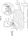
- the main casing includes a protrusion. The protrusion may extend through the lid in a state where the solvent cartridge is connected to the inlet port.
- the solvent cartridge may include a sleeve.
- the sleeve is positioned on an outer periphery of the discharge opening. The sleeve is inserted into the inlet port in a state where the solvent cartridge is connected to the inlet port.
- the sleeve may include a first thread at an outer peripheral surface of the sleeve.
- the main casing includes a second thread. The second thread is in threading engagement with the first thread in a state where the solvent cartridge is connected with the inlet port.
- the drum cartridge can accommodate solvent in the solvent casing.
- the drum cartridge may further include a drum frame.
- a developing cartridge is detachably attachable to the drum frame.
- the developing cartridge includes a toner casing.
- the toner casing can accommodate therein toner.
- the drum cartridge may include a transfer unit.
- the transfer unit transfers the toner that has been supplied onto the photosensitive drum to a sheet.
- the drum cartridge may be detachably attachable to a main casing.
- the main casing accommodates therein an applicator.
- the applicator applyies the solvent to the toner that has been transferred to the sheet.
- the charge electrode can be suppressed from getting dirty with the waste solvent even if the waste solvent is leaked from the tube.
- the waste solvent casing may support the sheet conveying roller
- a developing cartridge of the present disclosure includes a developing roller, and a casing.
- the casing includes a toner casing, and a solvent casing.
- the toner casing can accommodate therein toner.
- the solvent casing can accommodate therein solvent. The solvent dissolves the toner.
- the developing cartridge can accommodate the solvent in the solvent casing.
- the developing roller is rotatable about a developing axis.
- the developing axis extends in a first direction.
- the developing roller is positioned at one end portion in a second direction of the casing.
- the second direction crosses the first direction.
- the solvent casing is positioned at another end portion in the second direction of the casing. At least a portion of the toner casing may be positioned between the developing roller and the solvent casing in the second direction.
- the developing cartridge further includes an agitator.
- the agitator agitates toner in the toner casing.
- the agitator may be positioned between the developing roller and the solvent casing in the second direction.
- the developing cartridge may be detachably attachable to a drum cartridge.
- the drum cartridge includes a photosensitive drum.
- the drum cartridge is detachably attachable to a main casing.
- the developing cartridge is detachably attachable to the main casing in a state where the developing cartridge is attached to the drum cartridge.
- the main casing accommodates therein a transfer unit and an applicator.
- the transfer unit transfers toner on the photosensitive drum to a sheet.
- the applicator applies the solvent to the toner that has been transferred to the sheet.
- the solvent is applied to toner that has been transferred to the sheet.
- the solvent dissolves the toner on the sheet.
- the sheet cassette 3 can accommodate therein a sheet(s) S.
- the sheet S is, for example, a printing paper.
- the sheet(s) S accommodated in the sheet cassette 3 is transferred toward the photosensitive drum 4.
- the photosensitive drum 4 is rotatable about a drum axis A1.
- the drum axis A1 extends in a first direction.
- the photosensitive drum 4 extends in the first direction.
- the photosensitive drum 4 has a hollow cylindrical shape.
- the solvent cartridge 24 includes a solvent casing 24A, the first handle 24B, a second handle 24C, a cartridge guide 24D1, and a cartridge guide 24D2.
- the operation panel 29 is positioned on the upper surface of the main casing 2.
- the operation panel 29 is positioned away from the discharge tray 11 in the first direction.
- the operation panel 29 is positioned above the solvent cartridge 24 in a state where the solvent cartridge 24 is attached to the main casing 2.
- the operation panel 29 is electrically connected to the first circuit board 27.
- the operation panel 29 is operated by the user.
- the solvent cartridge 24 is positioned away from the developing cartridge 7 in the first direction.
- increasing in size of the image forming apparatus 1 in the up-down direction can be restrained in comparison with a configuration in which the developing cartridge 7 and the solvent cartridge 24 are arranged in the up-down direction in a state where the developing cartridge 7 and the solvent cartridge 24 are attached to the main casing 2.
- the first opening 2A and the second opening 2B are positioned at the one end portion E1 in the second direction of the main casing 2, as illustrated in Fig. 2 .
- the developing cartridge 7 is attachable to the main casing 2 through the first opening 2A in the second direction.
- the solvent cartridge 24 is attachable to the main casing 2 through the second opening 2B in the second direction.
- replacement of the developing cartridge 7 and the solvent cartridge 24 can be performed at one side in the second direction of the main casing 2.
- the replacement of the solvent cartridge 24 can be performed at the one side of the main casing 2 which is the same as the side in which the replacement of the developing cartridge 7 is performed.
- the second cover 22 makes contact with the solvent cartridge 24 in a state where the solvent cartridge 24 is attached to the main casing 2 and the second cover 22 is at the second closed position.
- the second cover 22 has the guide 22B1 and the guide 22B2 as illustrated in Fig. 2 .
- the guide 22B1 and the guide 22B2 guide the solvent cartridge 24 when attaching the solvent cartridge 24 to the main casing 2 while the second cover 22 is at the second open position.
- the solvent cartridge 24 can be guided toward the main casing 2 by making use of the second cover 22 positioned at the second open position.
- the main casing 2 has the guide 2D1 and the guide 2D2 as illustrated in Figs. 2 and 4 .
- the guide 2D1 and the guide 2D2 guide the solvent cartridge 24 during the attachment of the solvent cartridge 24 to the main casing 2.
- the solvent cartridge 24 can be guided inside the main casing 2.
- replacement of the sheet cassette 3 can be performed at the one side of the main casing 2 in the second direction.
- the replacement of the sheet cassette 3 can be performed at the side the same as the side in which the replacement of the developing cartridge 7 and the solvent cartridge 24 is performed with respect to the main casing 2.
- the first circuit board 27 is electrically connected to the pump 26 that pumps the solvent from the solvent cartridge 24 to the applicator 9, as illustrated in Fig. 7 .
- the first circuit board 27 and the solvent cartridge 24 are arranged in the second direction in a state where the solvent cartridge 24 is attached to the main casing 2.
- the first circuit board 27 is positioned close to the solvent cartridge 24 in the first direction.
- the developing cartridge 7 is positioned between the solvent cartridge 24 and the second circuit board 28 in the first direction, as illustrated in Fig. 7 .
- the second circuit board 28 is positioned on the opposite side of the developing cartridge 7 from the solvent cartridge 24 in the first direction.
- the solvent cartridge 24 can be suppressed from being electrified due to electric power supplied from the second circuit board 28 to the charging unit 5 and the applicator 9.
- the solvent cartridge 24 is attachable to the main casing 2 in a state where the solvent cartridge 24 is mounted on the second cover 22.
- the solvent cartridge 24 is attachable to the main casing 2 in the first direction.
- At least a portion of the solvent cartridge 24 is juxtaposed with the developing cartridge 7 in the first direction in a state where the developing cartridge 7 and the solvent cartridge 24 are attached to the main casing 2.
- the solvent cartridge 24 is positioned away from the developing cartridge 7 in the first direction in a state where the developing cartridge 7 and the solvent cartridge 24 are attached to the main casing 2.
- the second opening 2B may be positioned at an upper end portion of the main casing.
- the solvent cartridge 24 is attachable to the main casing 2 in the up-down direction.
- the solvent cartridge 24 is positioned away from the developing cartridge 7 in the first direction in a state where the developing cartridge 7 and the solvent cartridge 24 are attached to the main casing 2.
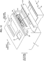
- the image forming apparatus 1 may include a single cover 20 instead of the first cover 21 and the second cover 22 as illustrated in Fig. 10 .
- the cover 20 is movable between a closed position (not illustrated) and an open position (see Fig. 10 ).
- the cover 20 closes the first opening 2A and the second opening 2B in a state where the cover 20 is at the closed position.
- the first opening 2A and the second opening 2B are opened in a state where the cover 20 is at the open position.
- the replacement of the developing cartridge 7 and the solvent cartridge 24 can be performed easily even in a case where the replacement of both the developing cartridge 7 and the solvent cartridge 24 is desired.
- the solvent cartridge 24 may be positioned on the opposite side of the first circuit board 27 from the developing cartridge 7 in the first direction in a state where the developing cartridge 7 and the solvent cartridge 24 are attached to the main casing 2.
- the second circuit board 28 may be positioned downward of the developing cartridge 7 in a state where the developing cartridge 7 and the solvent cartridge 24 are attached to the main casing 2.
- the sheet cassette 3 may be installed in the main casing 2 so as not to be attachable to or detachable from the main casing 2.
- the sheet cassette 3 includes a portion for accommodating therein the sheet S and movable through the third opening 2C between an interior position in which the portion is positioned inside the main casing 2 and an exterior position in which the portion is positioned outside the main casing 2.
- the guide 2D1 and the guide 2D2, and the guide 22B1 and the guide 22B2 may be grooves.
- the cartridge guide 24D1 and the cartridge guide 24D2 may be ribs.
- the developing cartridge 7 and the drum cartridge 23 may be detachably attachable to the main casing 2 independently of each other.
- the developing cartridge 7 may be integral with the drum cartridge 23.
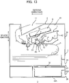
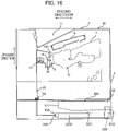
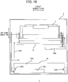
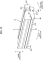
- An image forming apparatus 1 includes a main casing 2 (see Fig. 14 ), a cover 30 (see Fig. 14 ), a drum cartridge 31 (see Fig. 13 ), a solvent cartridge 32 (see Fig. 13 ), a supply pipe 33 (see Fig. 15 ), a pump 34 (see Fig. 15 ), a first circuit board 39A (see Fig. 15 ), and a second circuit board 39B (see Fig. 15 ).
- the main casing 2 has a first opening 35, a second opening 36, and a third opening 37.
- the main casing 2 includes a guide 38A (see Fig. 15 ) and a guide 38B (see Fig. 15 ).
- the first opening 35 is positioned at one end portion E1 in the second direction of the main casing 2.
- the second direction crosses the first direction.
- the developing cartridge 7 passes through the first opening 35 when the developing cartridge 7 is attached to the main casing 2.
- the drum cartridge 31 (see Fig. 13 ) is also attachable to the main casing 2 through the first opening 35.
- the developing cartridge 7 and the drum cartridge 31 are attachable to the main casing 2 in the second direction. Note that the developing cartridge 7 and the drum cartridge 31 those attached to the main casing 2 are detachable from the main casing 2 through the first opening 35.
- the second opening 36 is positioned at the one end portion E1 in the second direction of the main casing 2.
- the second opening 36 is positioned downward and away from the first opening 35.
- the second opening 36 is positioned on the opposite side of the third opening 37 from the first opening 35.
- the solvent cartridge 32 passes through the second opening 36 when the solvent cartridge 32 is attached to the main casing 2. That is, the drum cartridge 31 and the developing cartridge 7 are attached to the main casing 2 through the first opening 35 whereas the solvent cartridge 32 is attached to the main casing 2 through the second opening 36 positioned away from the first opening 35.
- the solvent cartridge 32 is attachable to the main casing 2 independently of the drum cartridge 31 and the developing cartridge 7.
- the drum cartridge 31 is attachable to the main casing 2 independently of the solvent cartridge 32.
- the solvent cartridge 32 is attachable to the main casing 2 in the second direction. Note that the solvent cartridge 32 attached to the main casing 2 is detachable from the main casing 2 through the second opening 36.
- the third opening 37 is positioned at the one end portion E1 in the second direction of the main casing 2.
- the sheet cassette 3 is attachable to the main casing 2 through the third opening 37.
- the sheet cassette 3 is attachable to the main casing 2 in the second direction. Note that the sheet cassette 3 attached to the main casing 2 is detachable from the main casing 2 through the third opening 37.
- the sheet cassette 3 is detachably attachable to the main casing 2 independently of the solvent cartridge 32. In other words, the solvent cartridge 32 is detachably attachable to the main casing 2 independently of the sheet cassette 3.
- the third opening 37 is positioned between the first opening 35 and the second opening 2B in the up-down direction.
- the sheet cassette 3 is positioned below the developing cartridge 7 in a state where the sheet cassette 3 is attached to the main casing 2.
- the sheet cassette 3 is positioned between the developing cartridge 7 and the solvent cartridge 32 in the up-down direction in a state where the developing cartridge 7, the solvent cartridge 32, and the sheet cassette 3 are attached to the main casing 2.
- the sheet cassette 3 includes the sheet handle 3A.
- the sheet handle 3A is positioned at the one end portion E1 in the second direction of the main casing 2 in a state where the sheet cassette 3 is attached to the main casing 2.
- the guide 38A is positioned inside the second opening 36.
- the guide 38A guides the solvent cartridge 32 when the solvent cartridge 32 is attached to the main casing 2.
- the guide 38A extends in the second direction.
- the guide 38A is a rib extending in the first direction.
- the guide 38B is positioned inside the second opening 36.
- the guide 38B is positioned away from the guide 38A in the first direction.
- the guide 38B guides the solvent cartridge 32 when the solvent cartridge 32 is attached to the main casing 2.
- the guide 38B extends in the second direction.
- the guide 38B is a rib extending in the first direction.
- the cover 30 is positioned at the one end portion E1 in the second direction of the main casing 2.
- the cover 30 is movable between a closed position (see Fig. 13 ) and an open position (see Fig. 14 ).
- the cover 30 is pivotally movable about a cover axis 30A.
- the cover axis 30A extends in the first direction.
- the cover 30 extends in the up-down direction in a state where the cover 30 is at the closed position.
- the cover 30 closes the first opening 35 in a state where the cover 30 is at the closed position.
- the cover 30 extends in the second direction in a state where the cover 30 is at the open position.
- the first opening 35 is opened when the cover 30 is at the open position.
- the drum cartridge 31 is attachable to the main casing 2.
- the drum cartridge 31 is attachable to the image forming apparatus 1.
- the drum cartridge 31 includes the photosensitive drum 4, the charging unit 5, and the transfer unit 8.
- the main casing 2 may include the transfer unit 8.
- the developing cartridge 7 is detachably attachable to the drum cartridge 31.
- the developing cartridge 7 is attachable to the main casing 2 in a state where the developing cartridge 7 is attached to the drum cartridge 31.
- the solvent cartridge 32 is positioned below the developing cartridge 7 in a state where the developing cartridge 7 and the solvent cartridge 32 are attached to the main casing 2. This arrangement can suppress increasing in size of the image forming apparatus 1 in the first direction. At least a portion of the exposure unit 6 is positioned upward of the developing cartridge 7 and the solvent cartridge 32 in a state where the developing cartridge 7 and the solvent cartridge 32 are attached to the main casing 2.
- the solvent cartridge 32 is positioned below the sheet cassette 3 in a state where the solvent cartridge 32 and the sheet cassette 3 are attached to the main casing 2.
- the solvent cartridge 32 is positioned downward of the applicator 9 in a state where the solvent cartridge 32 is attached to the main casing 2.
- the solvent cartridge 32 includes a solvent casing 32A, a cartridge handle 32B, a cartridge guide 32C, and a cartridge guide 32D.
- the solvent casing 32A can accommodate therein solvent.
- the solvent cartridge 32 can accommodate therein solvent.
- the solvent dissolves toner.
- the solvent casing 32A extends in the second direction in a state where the solvent cartridge 32 is attached to the main casing 2.
- the solvent casing 32A has a discharge opening 32E.
- the discharge opening 32E allows the solvent to be discharged therethrough from the solvent casing 32A to the supply pipe 33.
- the discharge opening 32E is positioned at one end portion E11 in the second direction of the solvent casing 32A.
- the cartridge handle 32B is positioned at another end portion E12 in the second direction of the solvent casing 32A in a state where the solvent cartridge 32 is attached to the main casing 2.
- the user moves the solvent cartridge 32 in the second direction when attaching the solvent cartridge 32 to the main casing 2 and when detaching the solvent cartridge 32 from the main casing 2.
- the cartridge handle 32B is grasped by the user.
- the cartridge guide 32C is positioned on a side surface 32S1 in the first direction of the solvent casing 32A.
- the cartridge guide 32C is in a form of a groove.
- the guide 38A of the main casing 2 is fitted into the cartridge guide 32C when the solvent cartridge 32 is attached to the main casing 2.
- the cartridge guide 32C is guided by the guide 38A. Accordingly, the solvent cartridge 32 is guided by the guide 38A in the second direction.
- the cartridge guide 32D is positioned on a side surface 32S2 in the first direction of the solvent casing 32A.
- the side surface 32S2 is positioned away from the side surface 32S1 in the first direction.
- the cartridge guide 32D is in a form of a groove.
- the guide 38B of the main casing 2 is fitted into the cartridge guide 32D when the solvent cartridge 32 is attached to the main casing 2.
- the cartridge guide 32D is guided by the guide 38B.
- the solvent cartridge 32 is guided by the guide 38B in the second direction.
- the supply pipe 33 has one end portion 33A and another end portion 33B.
- the one end portion 33A is connected to the discharge opening 32E of the solvent cartridge 32 in a state where the solvent cartridge 32 is attached to the main casing 2.
- the other end portion 33B is positioned away from the one end portion 33A.
- the other end portion 33B is connected to the applicator casing 14 of the applicator 9.
- the pump 34 is positioned between the one end portion 33A and the other end portion 33B of the supply pipe 33.
- the pump 34 pumps the solvent from the solvent cartridge 32 to the applicator 9.
- the pump 34 is driven in a state where the solvent cartridge 32 is attached to the main casing 2, the solvent accommodated in the solvent cartridge 32 is introduced into the applicator casing 14 of the applicator 9 through the discharge opening 32E and the supply pipe 33.
- the pump 34 is a gear pump.
- the first circuit board 39A is juxtaposed with the applicator 9 in the first direction.
- the first circuit board 39A is electrically connected to the pump 34.
- the first circuit board 39A is a control circuit board.
- the first circuit board 39A controls the pump 34.
- the second circuit board 39B is positioned to be spaced apart from the first circuit board 39A in the first direction.
- the second circuit board 39B is positioned on the opposite side of the applicator 9 from the first circuit board 39A in the first direction. In other words, the applicator 9 is positioned between the first circuit board 39A and the second circuit board 39B in the first direction.
- the second circuit board 39B is electrically connected to the charging unit 5 and the transfer unit 8.
- the second circuit board 39B applies a voltage to the charging unit 5 and the transfer unit 8.
- the second circuit board 39B is electrically connected to the applicator 9.
- the second circuit board 39B supplies electric power to the applicator 9.
- the second circuit board 39B is electrically connected to the developing cartridge 7.
- the second circuit board 39B applies a voltage to the developing cartridge 7.
- the second circuit board 39B is electrically connected to the developing roller 13.
- the second circuit board 39B applies a voltage to the developing roller 13.
- the solvent cartridge 32 is positioned downward of the developing cartridge 7 in a state where the developing cartridge 7 and the solvent cartridge 32 are attached to the main casing 2.
- enlargement of the image forming apparatus 1 in the first direction can be restrained in comparison with a configuration where the developing cartridge 7 and the solvent cartridge 32 are arranged in the first direction in a state where the developing cartridge 7 and the solvent cartridge 32 are attached to the main casing 2.
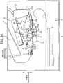
- the first opening 35 and the second opening 36 are positioned at the one end portion E1 in the second direction of the main casing 2, as illustrated in Fig. 14 .
- the developing cartridge 7 is attachable to the main casing 2 through the first opening 35 in the second direction.
- the solvent cartridge 32 is attachable to the main casing 2 through the second opening 36 in the second direction.
- the replacement of the developing cartridge 7 and the solvent cartridge 32 can be performed at one side in the second direction of the main casing 2.
- the replacement of the solvent cartridge 32 can be performed at the side of the main casing 2 which is the same as the side in which the replacement of the developing cartridge 7 is performed.
- the developing cartridge 7 and the solvent cartridge 32 can be replaced easily.
- the sheet handle 3A of the sheet cassette 3 is positioned at the one end portion E1 in the second direction of the main casing 2 as illustrated in Fig. 14 .
- replacement of the sheet cassette 3 can be performed at the one side of the main casing 2 in the second direction.
- the replacement of the sheet cassette 3 can be performed at the side the same as the side in which the replacement of the developing cartridge 7 and the solvent cartridge 32 is performed with respect to the main casing 2.
- an image forming apparatus 1 includes the main casing 2 described above, a cover 40, a drum cartridge 41, a solvent cartridge 42, a supply pipe 43, and a pump 44.
- the main casing 2 has an opening 45.
- the main casing 2 has one end portion 2E1 and another end portion 2E2 in the second direction.
- the second direction crosses the first direction.
- the other end portion 2E2 is spaced apart from the one end portion 2E1 in the second direction.
- the applicator 9 is positioned at the one end portion 2E1 of the main casing 2.
- the opening 45 is positioned at the other end portion 2E2 in the second direction of the main casing 2.
- the developing cartridge 7 and the solvent cartridge 42 pass through the opening 45 when the developing cartridge 7 and the solvent cartridge 42 are attached to the main casing 2.
- the developing cartridge 7 and the solvent cartridge 42 are attachable to the main casing 2 in the second direction. Note that the developing cartridge 7 and the solvent cartridge 42 those attached to the main casing 2 are detachable from the main casing 2 through the opening 45.
- the cover 40 is positioned at the other end portion 2E2 in the second direction of the main casing 2.
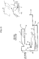
- the cover 40 is movable between a closed position (see Fig. 20 ) and an open position (see Fig. 21 ).
- the cover 40 is pivotally movable about a cover axis 40A.
- the cover axis 40A extends in the first direction.
- the cover 40 extends in the up-down direction in a state where the cover 40 is at the closed position.
- the cover 40 closes the opening 45 in a state where the cover 40 is at the closed position.
- the cover 40 extends in the second direction in a state where the cover 40 is at the open position.
- the opening 45 is opened in a state where the cover 40 is at the open position.
- the drum cartridge 41 is movable in the second direction through the opening 45 between an interior position (see Fig. 20 ) and an exterior position (see Fig. 21 ).
- the drum cartridge 41 is positioned inside the main casing 2 (see Fig. 20 ) in a state where the drum cartridge 41 is at the interior position.
- the drum cartridge 41 is positioned outside the main casing 2 (see Fig. 21 ) in a state where the drum cartridge 41 is at the exterior position.
- the drum cartridge 41 includes the photosensitive drum 4, the charging unit 5, and a drum frame 41A.
- the drum cartridge 41 may include the transfer unit 8.
- the main casing 2 includes the transfer unit 8.
- the transfer unit 8 can convey the sheet S in the second direction toward the applicator 9.
- the drum frame 41A extends in the second direction.
- the drum frame 41A supports the photosensitive drum 4.
- the drum frame 41A can support the developing cartridge 7 and the solvent cartridge 42.
- the drum cartridge 41 is movable in a state where the drum frame 41A supports the developing cartridge 7 and the solvent cartridge 42.
- the developing cartridge 7 is detachably attachable to the drum frame 41A.
- a state where the developing cartridge 7 is attached to the drum frame 41A denotes a state where the developing cartridge 7 is supported by a certain position of the drum frame 41A.
- the developing cartridge 7 may be movable relative to the drum frame 41A in a state where the developing cartridge 7 is attached to the drum frame 41A.
- the developing cartridge 7 is attached to the main casing 2 while the developing cartridge 7 is attached to the drum frame 41A and the drum cartridge 41 is at the interior position.
- the developing cartridge 7 is detachable from the drum frame 41A in a state where the drum cartridge 41 is at the exterior position, as indicated by an imaginary line in Fig. 21 .
- the solvent cartridge 42 is attached to the main casing 2 in a state where the solvent cartridge 42 is attached to the drum frame 41A and the drum cartridge 41 is at the interior position.
- the solvent cartridge 42 is detachable from the drum frame 41A in a state where the drum cartridge 41 is at the exterior position, as indicated by an imaginary line in Fig. 21 .
- the developing cartridge 7 since the developing cartridge 7 is positioned closer to the cover 40 than the solvent cartridge 42 is to the cover 40 in the second direction in a state where the developing cartridge 7 and the solvent cartridge 42 are attached to the main casing 2, the developing cartridge 7 can be replaced easily in a state where the cover 40 is at the open position (see Fig. 21 ). Further, this configuration can restrain the user's hands from getting dirty with solvent adhered to the solvent cartridge 42 during a process of attachment and detachment of the developing cartridge 7.
- the solvent cartridge 42 includes a solvent casing 42A.
- the solvent casing 42A can accommodate therein solvent.
- the solvent cartridge 42 can accommodate therein solvent.
- the solvent dissolves toner.
- the solvent casing 42A extends in the second direction in a state where the solvent cartridge 42 is attached to the main casing 2.
- the solvent casing 42A has a discharge opening 42B.
- the discharge opening 42B allows the solvent to be discharged therethrough from the solvent casing 42A to the supply pipe 43.
- the discharge opening 42B is positioned at one end portion E11 in the second direction of the solvent casing 42A.
- the solvent casing 42A has another end portion E12 positioned away from the one end portion E11 in the second direction.
- the one end portion E11 is positioned on the opposite side of the other end portion E 12 from the developing cartridge 7 in the second direction in a state where the developing cartridge 7 and the solvent cartridge 42 are attached to the main casing 2.
- the user's hands can be suppressed from getting dirty with the solvent adhered to the solvent cartridge 42 during a process of attachment and detachment of the developing cartridge 7.
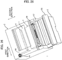
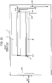
- the drum cartridge 48 is detachably attachable to the main casing 46 in the third direction in a state where the cover 47 is at the open position. Note that the drum cartridge 48 attached to the main casing 46 is detachable from the main casing 46 through the opening 46A.
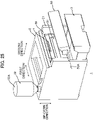
- the inlet port 55 allows solvent accommodated in the solvent cartridge 52 to be introduced into the main casing 2 therethrough.
- the inlet port 55 allows the solvent accommodated in the solvent cartridge 52 to be introduced into the supply pipe 53 (see Fig. 28 ) therethrough in a state where the solvent cartridge 52 is connected to the inlet port 55.
- the inlet port 55 is in communication with an internal space of the supply pipe 53 (see Fig. 28 ).
- the solvent casing 52A is positioned outside the main casing 2 in a state where the solvent cartridge 52 is connected to the inlet port 55.
- the solvent casing 52A is positioned upward of the main casing 2 in a state where the solvent cartridge 52 is connected to the inlet port 55.
- the solvent casing 52A extends in the up-down direction in a state where the solvent cartridge 52 is connected to the inlet port 55.
- the solvent casing 52A has a discharge opening 52E.
- the discharge opening 52E allows the solvent to be discharged therethrough from the solvent casing 52A to the supply pipe 53 (see Fig. 28 ).
- the discharge opening 52E is positioned at a lower end portion of the solvent casing 52A in a state where the solvent cartridge 52 is connected to the inlet port 55.
- the first circuit board 56 is positioned inside the main casing 2 (see Fig. 24 ).
- the first circuit board 56 extends in the second direction.
- the first circuit board 56 is positioned juxtaposed with the applicator 9 in the first direction.
- the first circuit board 56 is electrically connected to the pump 54.
- the first circuit board 56 is a control circuit board.
- the first circuit board 56 controls the pump 54.
- the replenishment of the main casing 2 with the solvent accommodated in the solvent cartridge 52 can be performed from an outside of the main casing 2 through the inlet port 55.
- the applicator 9 can be replenished with the solvent (see Fig. 28 ).
- the image forming apparatus 1 can be made compact in comparison with a configuration where the solvent cartridge 52 is accommodated inside the main casing 2.
- first thread 52C of the solvent cartridge 52 is in threading engagement with the second thread 58 of the main casing 2 in a state where the solvent cartridge 52 is connected to the main casing 2, as illustrated in Fig. 17 . Therefore, displacement of the discharge opening 52E of the solvent cartridge 52 from the inlet port 55 during the replenishment for the solvent can be suppressed. As a result, the replenishment of the main casing 2 with the solvent from the solvent cartridge 52 can be performed stably.
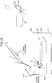
- an image forming apparatus 1 includes a drum cartridge 60.
- the drum cartridge 60 is detachably attachable to the main casing 2.
- the drum cartridge 60 is detachably attachable to the image forming apparatus 1.
- the drum cartridge 60 includes the photosensitive drum 4, the charging unit 5, the transfer unit 8, a drum frame 61 (see Fig. 31 ), a charge electrode 62A (see Fig. 32 ), a charge electrode 62B (see Fig. 32 ), a transfer electrode 62C (see Fig. 32 ), and a sheet conveying roller 63 (see Fig. 29 ).
- the main casing 2 may include the transfer unit 8 and the sheet conveying roller 63.
- the drum frame 61 extends in the first direction and the second direction.
- the second direction crosses the first direction.
- the second direction is perpendicular to the first direction. More preferably, the second direction is perpendicular to both the first direction and the third direction in a state where the drum cartridge 60 is attached to the main casing 2.
- the drum frame 61 has one end portion E21 and another end portion E22 in the first direction.
- the drum frame 61 has one end portion E31 and another end portion E32 in the second direction.
- the developing cartridge 7 is positioned at the other end portion E32 in the second direction of the drum frame 61 in a state where the developing cartridge 7 is attached to the drum frame 61.
- the drum frame 61 includes a side plate 64A, a side plate 64B, a solvent casing 65, a waste solvent casing 66, and a tube 67.
- the drum cartridge 60 includes the solvent casing 65, the waste solvent casing 66, and the tube 67.
- the side plate 64A is positioned at the one end portion E21 in the first direction of the drum frame 61.
- the side plate 64A extends in the second direction.
- the solvent casing 65 is positioned at the one end portion E31 in the second direction of the drum frame 61.
- the developing cartridge 7 is attached to the drum frame 61
- at least a portion of the solvent casing 65 is positioned on the opposite side of the photosensitive drum 4 from the developing cartridge 7 in the second direction.
- the photosensitive drum 4 is positioned between the solvent casing 65 and the developing cartridge 7 in the second direction.
- at least a portion of the solvent casing 65 is positioned between the photosensitive drum 4 and the applicator 9 in the second direction.
- the discharge opening 651 is positioned at the one end portion in the first direction of the solvent casing 65.
- the discharge opening 651 allows the solvent accommodated in the solvent casing 65 to be discharged therethrough.
- the tube 67 is positioned at the one end portion E21 in the first direction of the drum frame 61.
- the tube 67 extends in the second direction.
- the tube 67 has one end portion in the second direction connected to the waste solvent casing 66.
- the charge electrode 62A, the charge electrode 62B, and the transfer electrode 62C are mounted on the side plate 64B.
- the charge electrode 62A and the charge electrode 62B are electrically connected to the charging unit 5.
- the charging unit 5 includes a wire 5A (see Fig. 29 ), and a grid 5B (see Fig. 29 ).
- the charge electrode 62A is electrically connected to the wire 5A.
- the charge electrode 62B is electrically connected to the grid 5B.
- the transfer electrode 62C is electrically connected to the transfer unit 8.
- the sheet conveying roller 63 conveys the sheet S toward the photosensitive drum 4 and the transfer unit 8 in a state where the drum cartridge 60 is attached to the main casing 2. Specifically, the sheet conveying roller 63 makes contact with a sheet conveying roller 70 of the main casing 2 in a state where the drum cartridge 60 is attached to the main casing 2. The sheet conveying roller 70 of the main casing 2 will be described later.
- the sheet conveying roller 63 can convey the sheet S in cooperation with the sheet conveying roller 70 in a state where the drum cartridge 60 is attached to the main casing 2. Note that the sheet conveying roller 63 is in separation from the sheet conveying roller 70 in a state where the drum cartridge 60 is detached from the main casing 2, as illustrated in Fig. 30 .
- the main casing 2 includes a supply pipe 68A (see Fig. 29 ), a pump 68B (see Fig. 29 ), a waste solvent tray 68C (see Fig. 29 ), a discharge pipe 68D (see Fig. 29 ), a first circuit board 69A (see Fig. 33 ), a second circuit board 69B (see Fig. 33 ), and the sheet conveying roller 70 (see Fig. 29 ).
- the supply pipe 68A supplies solvent to the applicator 9.
- the supply pipe 68A has one end portion and another end portion.
- the one end portion of the supply pipe 68A is connected to the discharge opening 651 (see Fig. 31 ) of the drum cartridge 60 in a state where the drum cartridge 60 is attached to the main casing 2.
- the other end portion of the supply pipe 68A is positioned away from the one end portion of the supply pipe 68A.
- the other end portion of the supply pipe 68A is connected to the applicator casing 14 of the applicator 9.
- the pump 68B is positioned between the one end portion and the other end portion of the supply pipe 68A.
- the pump 68B pumps the solvent from the solvent casing 65 to the applicator 9.
- the pump 68B is driven in a state where the drum cartridge 60 is attached to the main casing 2
- the solvent accommodated in the solvent casing 65 is introduced into the applicator casing 14 of the applicator 9 through the discharge opening 651 and the supply pipe 68A.
- the solvent entered the applicator casing 14 is sprayed through the nozzles 15 onto the toner that has been transferred to the sheet S from the photosensitive drum 4.
- the sprayed solvent dissolves the toner on the sheet S.
- the pump 68B is a gear pump.
- the waste solvent tray 68C is positioned below the applicator 9.
- the waste solvent tray 68C is positioned to be spaced apart from the applicator 9.
- the sheet S on which toner has been transferred passes through a space between the applicator 9 and the waste solvent tray 68C.
- the waste solvent tray 68C accommodates therein the waste solvent.
- the waste solvent is solvent discharged from the applicator 9 but not applied to the sheet S. For example, in a case where printing operations are continuously performed on a first sheet S and a second sheet S subsequent to the first sheet S, solvent discharged from the applicator 9 to an interval between the first sheet S and the second sheet S is not applied to either of the first sheet S and the second sheet S, but is accommodated in the waste solvent tray 68C as the waste solvent.
- the discharge pipe 68D discharges the waste solvent from the applicator 9.
- the discharge pipe 68D has one end portion and another end portion.
- the one end portion of the discharge pipe 68D is connected to the other end portion in the second direction of the tube 67 (see Fig. 31 ).
- the other end portion of the discharge pipe 68D is positioned away from the one end portion of the discharge pipe 68D.
- the other end portion of the discharge pipe 68D is connected to the waste solvent tray 68C.
- the waste solvent in the waste solvent tray 68C enters the waste solvent casing 66 through the discharge pipe 68D and the tube 67.
- the first circuit board 69A is positioned at one end portion in the first direction of the main casing 2. In a state where the drum cartridge 60 is attached to the main casing 2, the first circuit board 69A is positioned to be spaced apart from the drum cartridge 60 in the first direction. In a state where the drum cartridge 60 is attached to the main casing 2, the first circuit board 69A is positioned on the opposite side of the one end portion E21 of the drum frame 61 from the other end portion E22 of the drum frame 61 in the first direction.
- the first circuit board 69A is electrically connected to the pump 68B (see Fig. 29 ). Specifically, the first circuit board 69A is a control circuit board.
- the first circuit board 69A controls the pump 68B.
- the second circuit board 69B is positioned to be spaced apart from the first circuit board 69A in the first direction.
- the second circuit board 69B In a state where the drum cartridge 60 is attached to the main casing 2, the second circuit board 69B is positioned on the opposite side of the drum cartridge 60 from the first circuit board 69A in the first direction. In other words, the drum cartridge 60 is positioned between the first circuit board 69A and the second circuit board 69B in the first direction.
- the second circuit board 69B is electrically connected to the charge electrode 62A, the charge electrode 62B, and the transfer electrode 62C.
- the sheet conveying roller 70 is positioned below the sheet conveying roller 63 in a state where the drum cartridge 60 is attached to the main casing 2.
- the sheet conveying roller 70 makes contact with the sheet conveying roller 63 in a state where the drum cartridge 60 is attached to the main casing 2.
- the sheet conveying roller 70 can convey sheet S in cooperation with the sheet conveying roller 63 in a state where the drum cartridge 60 is attached to the main casing 2.
- the supply pipe 68A for supplying the solvent from the solvent casing 65 to the applicator 9 can be shortened, thereby restraining complication of a piping arrangement from the solvent casing 65 to the applicator 9.
- enlargement of a capacity of the solvent casing 65 can be achieved by making use of a space between the photosensitive drum 4 and the applicator 9.
- the charge electrode 62A is positioned on the opposite side of the solvent casing 65 in the first direction from the tube 67 (see Fig. 31 ) through which the waste solvent flows.
- the charge electrode 62A can be restrained from getting dirty with the waste solvent even if leakage of the waste solvent from the tube 67 occurs.
- the transfer electrode 62C is positioned on the opposite side of the solvent casing 65 in the first direction from the tube 67 (see Fig. 31 ) through which the waste solvent flows.
- the transfer electrode 62C can be restrained from getting dirty with the waste solvent even if leakage of the waste solvent from the tube 67 occurs.
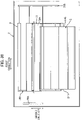
- a developing cartridge 7 according to the seventh embodiment extends in the first direction.
- the developing cartridge 7 has one end portion E41 and another end portion E42 in the first direction.
- the developing cartridge 7 includes a casing 71, an agitator 72 (see Fig. 34 ), a developing electrode 73, a storage medium 74, and a plurality of electrical contact surfaces 75.
- the casing 71 extends in the first direction and the second direction.
- the second direction crosses the first direction.
- the second direction is perpendicular to the first direction.
- the second direction is a direction defined by connecting the developing axis A2 (see Fig. 34 ) and an agitator axis A5 to each other.
- the agitator axis A5 will be described later.
- the casing 71 has one end portion E51 and another end portion E52 in the second direction.
- the developing roller 13 is positioned at the one end portion E51 in the second direction of the casing 71.
- the casing 71 includes the toner casing 12 described above, a solvent casing 71A, and a tube 71B.
- At least a portion of the toner casing 12 is positioned between the developing roller 13 and the solvent casing 71A in the second direction. In a state where the developing cartridge 7 is attached to the main casing 2, the toner casing 12 is positioned on the opposite side of the developing roller 13 from the photosensitive drum 4 in the second direction.
- the solvent casing 71A is positioned at the other end portion E52 in the second direction of the casing 71. In a state where the developing cartridge 7 is attached to the main casing 2, the solvent casing 71A is positioned on the opposite side of the toner casing 12 from the developing roller 13 in the second direction.
- the solvent casing 71A can accommodate therein solvent.
- the tube 71B is positioned at one end portion in the third direction of the casing 71.
- the third direction crosses the first direction and the second direction.
- the third direction is parallel to the up-down direction in a state where the developing cartridge 7 is attached to the main casing 2.
- the tube 71B extends in the second direction.
- the tube 71B has one end portion in the second direction in communication with the solvent casing 71A.
- the tube 71B has a discharge opening 71C.
- the discharge opening 71C is positioned at another end portion in the second direction of the tube 71B.
- the discharge opening 71C is positioned at the one end portion E51 in the second direction of the casing 71.
- the discharge opening 71C is positioned on the opposite side of the toner casing 12 from the solvent casing 71A in the second direction.
- the discharge opening 71C is positioned at a lower end portion of the casing 71.
- the solvent accommodated in the solvent casing 71A flows the tube 71B and is discharged through the discharge opening 71C.
- the discharge opening 71C allows the solvent accommodated in the solvent casing 71A to be discharged therethrough.
- the agitator 72 is positioned inside the toner casing 12.
- the agitator 72 is positioned between the developing roller 13 and the solvent casing 71A in the second direction.
- the agitator 72 is rotatable about the agitator axis A5.
- the agitator 72 makes rotations to agitate the toner in the toner casing 12.
- the agitator axis A5 extends in the first direction.
- the developing electrode 73 is positioned at the other end portion E42 in the first direction of the developing cartridge 7.
- the developing electrode 73 is mounted on the other end portion in the first direction of the casing 71.
- the developing electrode 73 is positioned away from the tube 71B and the discharge opening 71C in the first direction.
- the developing electrode 73 is electrically connected to the developing roller 13.
- the storage medium 74 is positioned at the other end portion E42 in the first direction of the developing cartridge 7.
- the storage medium 74 is mounted on the other end portion in the first direction of the casing 71.
- the storage medium 74 is positioned away from the tube 71B and the discharge opening 71C in the first direction.
- the storage medium 74 is an IC chip.
- the storage medium 74 has a flat plate shape.
- the storage medium 74 stores therein information related to the developing cartridge 7.
- Data related to the developing cartridge 7 is, for example, data indicative of whether the developing cartridge 7 is a new cartridge or an old cartridge, and data indicative of the number of sheets (or dot counts) printable using the developing cartridge 7.
- the plurality of electrical contact surfaces 75 are positioned on a surface of the storage medium 74.
- the storage medium 74 has the electrical contact surfaces 75.
- the plurality of electrical contact surfaces 75 are positioned at the other end portion E42 in the first direction of the developing cartridge 7.
- the plurality of electrical contact surfaces 75 are positioned away from the tube 71B and the discharge opening 71C in the first direction.
- the plurality of electrical contact surfaces 75 are electrically connected to the storage medium 74.
- the plurality of electrical contact surfaces 75 may be positioned away from the storage medium 74. In a case where the plurality of electrical contact surfaces 75 are positioned away from the storage medium 74, each of the electrical contact surfaces 75 is electrically connected to the storage medium 74 through a wiring.
- a single electrical contact surface 75 may be used.
- the image forming apparatus 1 includes a drum cartridge 78.
- the developing cartridge 7 is detachably attachable to the main casing 2 in a state where the developing cartridge 7 is attached to the drum cartridge 78.
- the drum cartridge 78 will be described below.
- the drum cartridge 78 is detachably attachable to the main casing 2. In other words, the drum cartridge 78 is detachably attachable to the image forming apparatus 1.
- the drum cartridge 78 includes the photosensitive drum 4 described above, the charging unit 5, the transfer unit 8, and a drum frame 78A.
- the drum frame 78A supports the photosensitive drum 4, the charging unit 5, and the transfer unit 8.
- the photosensitive drum 4 is positioned at one end portion in the second direction of the drum frame 78A.
- the developing cartridge 7 is detachably attachable to the drum frame 78A. In other words, the developing cartridge 7 is detachably attachable to the drum cartridge 78.
- the developing cartridge 7 is positioned at another end portion in the second direction of the drum frame 78A in a state where the developing cartridge 7 is attached to the drum frame 78A.
- the main casing 2 includes a supply pipe 76, and a pump 77.
- the supply pipe 76 supplies the solvent to the applicator 9.
- the supply pipe 76 has one end portion and another end portion. In a state where the developing cartridge 7 is attached to the main casing 2, the one end portion of the supply pipe 76 is connected to the tube 71B of the developing cartridge 7. In other words, in a state where the developing cartridge 7 is attached to the image forming apparatus 1, the supply pipe 76 is connected to the tube 71B positioned at the one end portion in the first direction of the developing cartridge 7. Hence, in a state where the developing cartridge 7 is attached to the image forming apparatus 1, the solvent casing 71A is connected to the supply pipe 76 of the image forming apparatus 1 through the tube 71B. The other end portion of the supply pipe 76 is positioned away from the one end portion of the supply pipe 76. The other end portion of the supply pipe 76 is connected to the applicator casing 14 of the applicator 9.
- the pump 77 is positioned between the one end portion and the other end portion of the supply pipe 76.
- the pump 77 pumps the solvent to the applicator 9.
- the solvent accommodated in the developing cartridge 7 is introduced into the applicator casing 14 of the applicator 9 through the tube 71B, the discharge opening 71C, and the supply pipe 76.
- the solvent entered the applicator casing 14 is sprayed through the nozzles 15 onto the toner that has been transferred to the sheet S from the photosensitive drum 4.
- the sprayed solvent dissolves the toner on the sheet S.
- the pump 77 is a gear pump.
- the developing electrode 73 can be restrained from getting dirty with the solvent even if the solvent is leaked from the supply pipe 76.
- the electrical contact surfaces 75 can be restrained from getting dirty with the solvent even if leakage of the solvent from the supply pipe 76 occurs.
- the supply pipe 78B is positioned at one end portion in the first direction of the drum cartridge 78.
- the drum frame 78A supports the supply pipe 78B.
- the supply pipe 78B In a state where the drum cartridge 78 is attached to the main casing 2, the supply pipe 78B is positioned upward of the photosensitive drum 4.
- one end portion of the supply pipe 78B In a state where the developing cartridge 7 is attached to the drum cartridge 78, one end portion of the supply pipe 78B is connected to the solvent casing 71A.
- the solvent casing 71A is connected to the supply pipe 78B of the drum cartridge 78 in a state where the developing cartridge 7 to the drum cartridge 78.
- Another end portion of the supply pipe 78B is connected to the applicator casing 14 of the applicator 9 in a state where the drum cartridge 78 is attached to the main casing 2, thereby allowing the solvent accommodated in the solvent casing 71A to be supplied to the applicator 9 through the supply pipe 78B.
- the supply pipe 78B may be positioned downward of the photosensitive drum 4 in a state where the drum cartridge 78 is attached to the main casing 2.
- the drum cartridge 78 may be dispensed with in the image forming apparatus 1.
- the photosensitive drum 4, the charging unit 5, and the transfer unit 8 are fixed to the main casing 2.
- the developing cartridge 7 is detachably attachable to the main casing 2.
- the image forming apparatus 1 may include a first circuit board 79A and a second circuit board 79B.
- the first circuit board 79A is positioned at one end portion in the first direction of the main casing 2. In a state where the developing cartridge 7 is attached to the main casing 2, the first circuit board 79A is positioned to be spaced apart from the developing cartridge 7 in the first direction. In a state where the developing cartridge 7 is attached to the main casing 2, the first circuit board 79A is positioned on the opposite side of the one end portion E41 of the developing cartridge 7 from the other end portion E42 of the developing cartridge 7 in the first direction.
- the first circuit board 79A is electrically connected to the pump 77 (see Fig. 34 ). Specifically, the first circuit board 79A is a control circuit board. The first circuit board 79A controls the pump 77.
- the second circuit board 79B is positioned to be spaced apart from the first circuit board 79A in the first direction. In a state where the developing cartridge 7 is attached to the main casing 2, the second circuit board 79B is positioned on the opposite side of the developing cartridge 7 from the first circuit board 79A in the first direction. In other words, the developing cartridge 7 is positioned between the first circuit board 79A and the second circuit board 79B in the first direction. In a state where the developing cartridge 7 is attached to the main casing 2, the second circuit board 79B is electrically connected to the developing electrode 73 (see Fig. 35 ). The second circuit board 79B applies a voltage to the developing roller 13.
- the second circuit board 79B is electrically connected to an electrode (not illustrated) of the drum cartridge 78.
- the second circuit board 79B applies a voltage to the charging unit 5.
- the second circuit board 79B is electrically connected to the applicator 9.
- the second circuit board 79B supplies electric power to the applicator 9.
- the second circuit board 79B is electrically connected to the electrical contact surfaces 75 (see Fig. 35 ).
- the second circuit board 79B supplies electric power to the storage medium 74.
Landscapes
- Physics & Mathematics (AREA)
- General Physics & Mathematics (AREA)
- Engineering & Computer Science (AREA)
- Computer Vision & Pattern Recognition (AREA)
- Electrophotography Configuration And Component (AREA)
- Fixing For Electrophotography (AREA)
Abstract
Description
- The present disclosure relates to an image forming apparatus, a drum cartridge, and a developing cartridge.
- A conventional image forming apparatus includes a main casing, a photosensitive drum, a developing cartridge, a transfer unit, and an applicator. The developing cartridge supplies toner onto the photosensitive drum. The transfer unit transfers toner that has been supplied onto the photosensitive drum to a sheet. The applicator applies solvent to the toner that has been transferred to the sheet (refer to
PTL 1 mentioned below). - [PTL 1]
Japanese Patent Application Publication No. 2017-68098 - In the image forming apparatus described in
PTL 1, it is desired that a cartridge that can accommodate therein solvent is provided, or solvent is supplied into the main casing. - In view of the foregoing, it is an object of the present disclosure to provide: an image forming apparatus in which a solvent cartridge that can accommodate therein solvent can be replaced independently of a developing cartridge; an image forming apparatus in which solvent can be supplied into a main casing; a drum cartridge that can accommodate therein solvent; and a developing cartridge that can accommodate therein solvent.
-
- (1) An image forming apparatus according to the present disclosure includes: a main casing; a photosensitive drum; a developing cartridge; a transfer unit; a solvent cartridge; an applicator; and a heater.
- The photosensitive drum is rotatable about a drum axis. The drum axis extends in a first direction.
- The developing cartridge includes a toner casing. The toner casing can accommodate therein toner. The developing cartridge supplies the toner onto the photosensitive drum. The developing cartridge is detachably attachable to the main casing.
- The transfer unit transfers the toner that has been supplied onto the photosensitive drum to a sheet.
- The solvent cartridge includes a solvent casing. The solvent casing can accommodate therein solvent. The solvent dissolves the toner. The solvent cartridge is detachably attachable to the main casing independently of the developing cartridge.
- The applicator applies the solvent to the toner that has been transferred to the sheet.
- The heater heats the sheet on which the solvent has been applied to the toner by the applicator.
- With this configuration, the solvent cartridge that can accommodate therein solvent can be replaced independently of the developing cartridge.
- (2) The solvent cartridge is positioned away from the developing cartridge in the first direction in a state where the developing cartridge and the solvent cartridge are attached to the main casing.
- With this configuration, increasing in size of the image forming apparatus in a direction crossing the first direction can be restrained.
- (3) The main casing may have a first opening and a second opening. The developing cartridge passes through the first opening when the developing cartridge is attached to the main casing. The solvent cartridge passes through the second opening when the solvent cartridge is attached to the main casing.
- (4) The image forming apparatus may include a first cover and a second cover. The first cover is movable between a first closed position and a first open position. The first cover closes the first opening in a state where the first cover is at the first closed position. The first opening is opened in a state where the first cover is at the first open position. The second cover is provided independently of the first cover. The second cover is movable between a second closed position and a second open position. The second cover closes the second opening in a state where the second cover is at the second closed position. The second opening is opened in a state where the second cover is at the second open position.
- (5) The first opening and the second opening may be positioned at one end portion of the main casing in a second direction. The second direction crosses the first direction. The developing cartridge and the solvent cartridge may be attachable to the main casing in the second direction.
- With this configuration, the developing cartridge and the solvent cartridge can be replaced at one side of the main casing in the second direction. In other words, the solvent cartridge can be replaced at the side the same as the developing cartridge with respect to the main casing.
- Accordingly, the developing cartridge and the solvent cartridge can be replaced easily.
- (6) The solvent casing has a discharge opening. The discharge opening allows the solvent to be discharged therethrough. The discharge opening is positioned at one end portion in the second direction of the solvent casing. The solvent cartridge may include a first handle. The first handle is positioned at another end portion in the second direction of the solvent casing. The first handle is positioned closer to the second cover than the discharge opening is to the second cover in the second direction.
- (7) The second cover may make contact with the solvent cartridge in a state where the solvent cartridge is attached to the main casing and the second cover is at the second closed position.
- With this configuration, detachment of the solvent cartridge from the main casing can be restrained using the second cover.
- (8) The second cover may make contact with the first handle in a state where the solvent cartridge is attached to the main casing and the second cover is at the second closed position.
- (9) The first cover may be pivotally movable about a first cover axis extending in the first direction. The second cover may be pivotally movable about a second cover axis extending in the first direction.
- (10) The second cover may include a first guide. The first guide guides the solvent cartridge when the solvent cartridge is attached to the main casing in a state where the second cover is at the second open position.
- With this configuration, the solvent cartridge can be guided toward the main casing using the second cover positioned at the second open position.
- Consequently, the solvent cartridge is attachable to the main casing easily.
- (11) The main casing may include a second guide. The second guide guides the solvent cartridge when the solvent cartridge is attached to the main casing
- With this configuration, the solvent cartridge can be guided inside the main casing.
- As a result, the solvent cartridge is attachable to the main casing more easily.
- (12) The solvent cartridge may include a cartridge guide. The cartridge guide is guided by the first guide and the second guide.
- (13) The second opening may be positioned at one end portion in the first direction of the main casing. The solvent cartridge may be attachable to the main casing in the first direction.
- (14) The second cover may be pivotally movable about a second cover axis extending in the second direction.
- (15) The image forming apparatus may include a cover. The cover is movable between a closed position and an open position. The cover closes the first opening and the second opening in a state where the cover is at the closed position. The first opening and the second opening are opened in a state where the cover is at the open position.
- With this configuration, the first opening and the second opening can be opened and closed by a single cover. Accordingly, the developing cartridge and the solvent cartridge can be replaced easily when both the developing cartridge and the solvent cartridge needs to be replaced.
- (16) The image forming apparatus may further include a drum cartridge. The drum cartridge includes the photosensitive drum. The drum cartridge is detachably attachable to the main casing independently of the solvent cartridge. The drum cartridge is detachably attachable to the main casing through the first opening.
- (17) The developing cartridge may be detachably attachable to the drum cartridge.
- (18) The image forming apparatus may further include a sheet cassette. The sheet cassette can accommodate therein the sheet. The sheet cassette is detachably attachable to the main casing independently of the solvent cartridge. The sheet cassette is positioned below the developing cartridge in a state where the sheet cassette is attached to the main casing.
- (19) The solvent cartridge may be positioned away from the sheet cassette in the first direction in a state where the solvent cartridge and the sheet cassette are attached to the main casing.
- (20) The solvent cartridge may be juxtaposed with the sheet cassette in the first direction in a state where the solvent cartridge and the sheet cassette are attached to the main casing.
- (21) The sheet cassette may include a sheet handle. The sheet handle may be positioned at one end portion in the second direction of the main casing in a state where the sheet cassette is attached to the main casing.
- With this configuration, the sheet cassette can be replaced at the one side in the second direction of the main casing.
- (22) The solvent cartridge may be positioned downward of the applicator in a state where the solvent cartridge is attached to the main casing.
- (23) The image forming apparatus may further include a pump. The pump pumps the solvent from the solvent cartridge to the applicator.
- (24) The image forming apparatus further includes a first circuit board. The first circuit board may be juxtaposed with the solvent cartridge in the second direction in a state where the solvent cartridge is attached to the main casing. The first circuit board is electrically connected to the pump.
- In the above configuration, the first circuit board is electrically connected to the pump that pumps the solvent cartridge to the applicator. The first circuit board is positioned close to the solvent cartridge in the first direction.
- Accordingly, a wiring for connecting the first circuit board to the pump can be shortened.
- (25) The image forming apparatus further includes a second circuit board, and a charging unit. The second circuit board is positioned away from the first circuit board in the first direction. The charging unit charges a surface of the photosensitive drum. The second circuit board may apply a voltage to the charging unit.
- (26) The applicator may be a spraying device of an electrostatic spraying type. The second circuit board may supply electric power to the applicator.
- (27) The developing cartridge may be positioned between the solvent cartridge and the second circuit board in the first direction.
- In this configuration, the second circuit board is positioned on the opposite side of the developing cartridge from the solvent cartridge in the first direction.
- With the above positional relationship, the solvent cartridge can be suppressed from being electrified due to electric power supplied from the second circuit board to the charging unit and the applicator.
- (28) The image forming apparatus may further include a discharge tray. The sheet that has moved past the applicator is discharged onto the discharge tray. The discharge tray is positioned above the developing cartridge in a state where the developing cartridge is attached to the main casing.
- (29) The image forming apparatus may further include an operation panel. The operation panel is positioned away from the discharge tray in the first direction. The operation panel is positioned above the solvent cartridge in a state where the solvent cartridge is attached to the main casing.
- (30) At least a portion of the solvent cartridge may be juxtaposed with the developing cartridge in the first direction in a state where the developing cartridge and the solvent cartridge are attached to the main casing.
- (31) The solvent cartridge may be positioned below the developing cartridge in a state where the developing cartridge and the solvent cartridge are attached to the main casing.
- In this configuration, the solvent cartridge is positioned below the developing cartridge in a state where the developing cartridge and the solvent cartridge are attached to the main casing.
- This configuration can suppress increasing in size of the image forming apparatus in the first direction.
- (32) The sheet cassette may be detachably attachable to the main casing in the second direction.
- (33) The solvent cartridge may be positioned below the sheet cassette in a state where the solvent cartridge and the sheet cassette are attached to the main casing.
- (34) The solvent cartridge may be positioned within the sheet cassette in a state where the solvent cartridge and the sheet cassette are attached to the main casing.
- (35) The image forming apparatus may further include an exposure unit. The exposure unit can expose the photosensitive drum to light. At least a portion of the exposure unit is positioned upward of the developing cartridge and the solvent cartridge in a state where the developing cartridge and the solvent cartridge are attached to the main casing.
- (36) The applicator may be positioned at one end portion in the second direction of the main casing. The main casing may have an opening. The developing cartridge and the solvent cartridge pass through the opening when the developing cartridge and the solvent cartridge are attached to the main casing. The opening is positioned at another end portion in the second direction of the main casing.
- The image forming apparatus includes a cover. The cover is movable between a closed position and an open position. The cover closes the opening in a state where the cover is at the closed position. The opening is opened in a state where the cover is at the open position. The cover is positioned at the other end portion in the second direction of the main casing.
- The developing cartridge and the solvent cartridge may be positioned between the applicator and the cover in the second direction, and the solvent cartridge may be positioned closer to the applicator than the developing cartridge is to the applicator in a state where the developing cartridge and the solvent cartridge are attached to the main casing and the cover is at the closed position.
- With the above configuration, the solvent cartridge that can accommodate therein solvent can be replaced independently of the developing cartridge.
- Further, the developing cartridge and the solvent cartridge are positioned between the applicator and the cover in the second direction, and the solvent cartridge is positioned closer to the applicator than the developing cartridge is to the applicator in a state where the developing cartridge and the solvent cartridge are attached to the main casing and the cover is at the closed position.
- Accordingly, a supply pipe for connecting the solvent cartridge to the applicator can be shortened. Also, since the developing cartridge is positioned closer to the cover than to the solvent cartridge is to the cover in the second direction, the developing cartridge can be replaced easily in a state where the cover is at the open position.
- Further, during attachment and detachment operation of the developing cartridge, a user's hands can be suppressed from getting dirty with solvent attached to the solvent cartridge.
- (37) The drum cartridge may include a drum frame. The drum cartridge may be movable in the second direction between an interior position and an exterior position. The drum cartridge is positioned inside the main casing in a state where the drum cartridge is at the interior position. The drum cartridge is positioned outside the main casing in a state where the drum cartridge is at the exterior position. The developing cartridge may be detachably attachable to the drum frame. The solvent cartridge may be detachably attachable to the drum frame independently of the developing cartridge.
- (38) The photosensitive drum may be positioned between the solvent cartridge and the cover in the second direction and the solvent cartridge may be positioned closer to the applicator than the photosensitive drum is to the applicator in the second direction in a state where the developing cartridge, the drum cartridge, and the solvent cartridge are attached to the main casing and the cover is at the closed position.
- (39) The image forming apparatus may include a drawer. The drawer is movable between an interior position and an exterior position. The drawer is positioned inside the main casing in a state where the drawer is at the interior position. The drawer is positioned outside the main casing in a state where the drawer is at the exterior position. The drawer is not detachable from the main casing. In a state where the drawer is at the exterior position, the developing cartridge may be detachably attachable to the drawer. In a state where the drawer is at the exterior position, the solvent cartridge may be detachably attachable to the drawer independently of the developing cartridge.
- (40) The developing cartridge may include the photosensitive drum. The photosensitive drum may be positioned between the applicator and the cover in the second direction in a state where the developing cartridge and the solvent cartridge are attached to the drawer, the drawer is at the interior position, and the cover is at the closed position. The solvent cartridge may be positioned closer to the applicator than the photosensitive drum is to the applicator in the second direction in a state where the developing cartridge and the solvent cartridge are attached to the drawer, the drawer is at the interior position, and the cover is at the closed position.
- (41) The opening may be positioned above the developing cartridge and the solvent cartridge in a state where the developing cartridge and the solvent cartridge are attached to the main casing. The cover may be positioned above the developing cartridge and the solvent cartridge in a state where the developing cartridge and the solvent cartridge are attached to the main casing. The cover is pivotally movable about a cover axis. The cover axis extends in the first direction.
- The solvent cartridge may be positioned closer to the applicator than the developing cartridge is to the applicator in a state where the developing cartridge and the solvent cartridge are attached to the main casing and the cover is at the closed position.
- With this configuration, the solvent cartridge that can accommodate therein solvent can be replaced independently of the developing cartridge.
- Further, the solvent cartridge is positioned closer to the applicator than the developing cartridge is to the applicator in a state where the developing cartridge and the solvent cartridge are attached to the main casing.
- With this configuration, the supply pipe for connecting the solvent cartridge to the applicator can be shortened.
- Further, the user's hands can be suppressed from getting dirty with solvent attached to the solvent cartridge during attachment and detachment operation of the developing cartridge.
- (42) The cover axis may be positioned at the one end portion in the second direction of the main casing. The cover axis may be positioned farther away from the solvent cartridge than the applicator is from the solvent cartridge in the second direction in a state where the developing cartridge and the solvent cartridge are attached to the main casing.
- With this configuration, the solvent cartridge can be replaced easily when the cover is at the open position.
- (43) The developing cartridge and the solvent cartridge may be detachably attachable to the main casing in a third direction crossing the first direction and the second direction.
- (44) The image forming apparatus may include a drum cartridge. The drum cartridge includes the photosensitive drum and a drum frame. The developing cartridge is attachable to the drum frame. The drum cartridge may be detachably attachable to the main casing in the third direction.
- (45) The transfer unit may be able to convey the sheet toward the applicator in the second direction.
- (46) The image forming apparatus may include a supply pipe. The supply pipe allows the solvent to be supplied from the solvent cartridge to the applicator therethrough. The supply pipe may be positioned between the applicator and the solvent cartridge in the second direction in a state where the solvent cartridge is attached to the main casing.
- (47) The main casing may have an inlet port. The inlet port allows solvent in a solvent cartridge to enter the main casing therethrough in a state where the solvent cartridge is connected to the main casing. The inlet port is positioned on an outer surface of the main casing.
- In this configuration, the inlet port of the main casing allows the solvent in the solvent cartridge to enter the main casing therethrough in a state where the solvent cartridge is connected to the main casing. Accordingly, the solvent in the solvent cartridge can be supplied into the main casing.
- As a result, the image forming apparatus can be made compact in comparison with a case where the solvent cartridge is accommodated in the main casing.
- (48) The inlet port may be positioned on an upper surface of the main casing.
- With this configuration, the solvent can be introduced into the main casing easily by virtue of a gravitational force.
- (49) The main casing may include a discharge tray. The discharge tray is positioned on the upper surface of the main casing. The sheet that has moved past the applicator is discharged onto the discharge tray. The inlet port may be positioned away from the discharge tray in the first direction.
- (50) The inlet port may be positioned away from the developing cartridge in the first direction.
- (51) The inlet port may be positioned away from the applicator in the first direction.
- (52) The image forming apparatus may further include a pump. The pump pumps the solvent to the applicator.
- (53) The image forming apparatus may further include a first circuit board. The first circuit board may be positioned between the developing cartridge and the inlet port in the first direction. The first circuit board may be electrically connected to the pump.
- (54) The solvent cartridge may include a solvent casing, and a lid. The solvent casing can accommodate therein the solvent. The solvent casing has a discharge opening. The discharge opening allows the solvent to be discharged from the solvent casing therethrough. The lid closes the discharge opening. The main casing includes a protrusion. The protrusion may extend through the lid in a state where the solvent cartridge is connected to the inlet port.
- (55) The solvent cartridge may include a sleeve. The sleeve is positioned on an outer periphery of the discharge opening. The sleeve is inserted into the inlet port in a state where the solvent cartridge is connected to the inlet port.
- (56) The sleeve may include a first thread at an outer peripheral surface of the sleeve. The main casing includes a second thread. The second thread is in threading engagement with the first thread in a state where the solvent cartridge is connected with the inlet port.
- With this configuration, displacement of the discharge opening of the solvent cartridge from the inlet port of the main casing during supply of solvent can be restrained, thereby ensuring the supply of the solvent from the solvent cartridge into the main casing.
- (57) A drum cartridge of the present disclosure includes a photosensitive drum, and a solvent casing.
- The solvent casing can accommodate therein solvent. The solvent dissolves toner.
- With this configuration, the drum cartridge can accommodate solvent in the solvent casing.
- (58) The drum cartridge may further include a drum frame. A developing cartridge is detachably attachable to the drum frame. The developing cartridge includes a toner casing. The toner casing can accommodate therein toner.
- (59) The photosensitive drum is rotatable about a drum axis. The drum axis extends in a first direction. The solvent casing may be positioned at one end portion in a second direction of the drum frame. The second direction crosses the first direction. The developing cartridge may be positioned at another end portion in the second direction of the drum frame in a state where the developing cartridge is attached to the drum frame. The photosensitive drum may be positioned between the solvent casing and the developing cartridge in the second direction in a state where the developing cartridge is attached to the drum frame.
- (60) The drum cartridge may include a transfer unit. The transfer unit transfers the toner that has been supplied onto the photosensitive drum to a sheet.
- (61) The drum cartridge may be detachably attachable to a main casing. The main casing accommodates therein an applicator. The applicator applyies the solvent to the toner that has been transferred to the sheet.
- (62) At least a portion of the solvent casing may be positioned between the photosensitive drum and the applicator in the second direction in a state where the drum cartridge is attached to the main casing.
- In this configuration, at least a portion of the solvent casing is positioned close to the applicator in the second direction in a state where the drum cartridge is attached to the main casing.
- Accordingly, the supply pipe for supplying the solvent from the solvent casing to the applicator can be shortened, whereby complication of pipe arrangement from the solvent casing to the applicator can be suppressed.
- Further, the solvent cartridge with a large capacity can be made using a space between the photosensitive drum and the applicator.
- (63) The drum cartridge may further include a waste solvent casing. The waste solvent casing can accommodate therein waste solvent. The waste solvent is discharged from the applicator.
- With this configuration, the drum cartridge can accommodate waste solvent in the waste solvent casing.
- (64) The waste toner casing may be positioned on the opposite side of the photosensitive drum from the solvent casing in the second direction.
- (65) The drum cartridge may further include a charging unit. The charging unit charges a surface of the photosensitive drum. The waste solvent casing may be positioned on the opposite side of the photosensitive drum from the charging unit in a third direction. The third direction crosses both the first direction and the second direction.
- (66) The drum cartridge may further include a charge electrode, and a tube. The charge electrode is electrically connected to the charging unit. The tube is connected to the waste solvent casing. The charge electrode may be positioned on the opposite side of the solvent casing from the tube in the first direction.
- With this configuration, the charge electrode can be suppressed from getting dirty with the waste solvent even if the waste solvent is leaked from the tube.
- (67) The drum cartridge may further include a transfer electrode. The transfer electrode is electrically connected to the transfer unit. The transfer electrode may be positioned on the opposite side of the solvent casing from the tube in the first direction.
- With this configuration, the transfer electrode can be suppressed from getting dirty with the waste solvent even if the waste solvent is leaked from the tube.
- (68) The waste solvent casing may support the developing cartridge in a state where the developing cartridge is attached to the drum frame.
- (69) The drum cartridge may include a sheet conveying roller. The sheet conveying roller conveys the sheet toward the photosensitive drum and the transfer unit. The sheet conveying roller is rotatable about a conveying axis. The conveying axis extends in the first direction.
- (70) The waste solvent casing may support the sheet conveying roller
- (71) The transfer unit may be a transfer roller. The transfer roller is rotatable about a transfer axis. The transfer axis extends in the first direction.
- (72) The solvent is applied to toner that has been transferred from the photosensitive drum to the sheet. The solvent dissolves the toner on the sheet.
- (73) A developing cartridge of the present disclosure includes a developing roller, and a casing. The casing includes a toner casing, and a solvent casing. The toner casing can accommodate therein toner. The solvent casing can accommodate therein solvent. The solvent dissolves the toner.
- With this configuration, the developing cartridge can accommodate the solvent in the solvent casing.
- (74) The developing roller is rotatable about a developing axis. The developing axis extends in a first direction. The developing roller is positioned at one end portion in a second direction of the casing. The second direction crosses the first direction. The solvent casing is positioned at another end portion in the second direction of the casing. At least a portion of the toner casing may be positioned between the developing roller and the solvent casing in the second direction.
- (75) The developing cartridge further includes an agitator. The agitator agitates toner in the toner casing. The agitator may be positioned between the developing roller and the solvent casing in the second direction.
- (76) The developing cartridge may be detachably attachable to a drum cartridge. The drum cartridge includes a photosensitive drum.
- (77) The drum cartridge is detachably attachable to a main casing. The developing cartridge is detachably attachable to the main casing in a state where the developing cartridge is attached to the drum cartridge. The main casing accommodates therein a transfer unit and an applicator. The transfer unit transfers toner on the photosensitive drum to a sheet. The applicator applies the solvent to the toner that has been transferred to the sheet.
- (78) The solvent casing may be connected to a supply pipe of the drum cartridge in a state where the developing cartridge is attached to the drum cartridge. The supply pipe supplies the solvent to the applicator.
- (79) The solvent casing may be connected to a supply pipe in the main casing in a state where the developing cartridge is attached to the main casing.
- (80) The developing cartridge further includes a developing electrode. The developing electrode is electrically connected to the developing roller. The supply pipe may be connected to one end portion in the first direction of the developing cartridge in a state where the developing cartridge is attached to the main casing. The developing electrode may be positioned at another end portion in the first direction of the developing cartridge.
- With this configuration, the developing electrode can be suppressed from getting dirty with the solvent even if the solvent is leaked from the tube.
- (81) The developing cartridge further includes a storage medium. The storage medium has an electrical contact surface. The electrical contact surface may be positioned at the other end portion in the first direction of the developing cartridge.
- With this configuration, the electrical contact surface can be suppressed from getting dirty with the solvent even if the solvent is leaked from the tube.
- (82) The storage medium may store therein information related to the developing cartridge.
- (83) The storage medium may be positioned at the the other end portion in the first direction of the developing cartridge.
- (84) The solvent is applied to toner that has been transferred to the sheet. The solvent dissolves the toner on the sheet.
- According to the image forming apparatus of the present disclosure, replacement of the solvent cartridge that can accommodate therein solvent can be performed independently of the developing cartridge. According to the image forming apparatus of the present disclosure, solvent accommodated in the solvent cartridge can be supplied to the main casing. The drum cartridge according to the present disclosure can accommodate therein solvent. The developing cartridge according to the present disclosure can accommodate therein solvent.
-
- [
Fig. 1] Fig. 1 is a schematic diagram illustrating a configuration of an image forming apparatus. - [
Fig. 2] Fig. 2 is a perspective view of the image forming apparatus according to a first embodiment. - [
Fig. 3] Fig. 3 is a front view of the image forming apparatus illustrated inFig. 2 . - [
Fig. 4] Fig. 4 is a perspective view of the image forming apparatus illustrated inFig. 2 as viewed from an angle different from that inFig. 2 . In Fig. 4A, a solvent cartridge is detached from a main casing. - [
Fig. 5] Fig. 5 is a cross-sectional view taken along a line A-A inFig. 3 . - [
Fig. 6] Fig. 6A is a perspective view of the solvent cartridge according to the first embodiment, andFig. 6B is another perspective view of the solvent cartridge according to the first embodiment as viewed from an angle different from that inFig. 6A . - [
Fig. 7] Fig. 7 is an explanatory view of a positional relationship among a developing cartridge, the solvent cartridge, a first circuit board, and a second circuit board in the first embodiment. - [
Fig. 8] Fig. 8 illustrates a first modification to the first embodiment. - [
Fig. 9] Fig. 9 illustrates a second modification to the first embodiment. - [
Fig. 10] Fig. 10 illustrates a third modification to the first embodiment. - [
Fig. 11] Fig. 11 illustrates a fourth modification to the first embodiment. - [
Fig. 12] Fig. 12 illustrates a fifth modification to the first embodiment. - [
Fig. 13] Fig. 13 is a schematic diagram illustrating a configuration of an image forming apparatus according to a second embodiment. - [
Fig. 14] Fig. 14 is a perspective view of the image forming apparatus according to the second embodiment. - [
Fig. 15] Fig. 15 is an explanatory view of a positional relationship among a developing cartridge, a drum cartridge, a solvent cartridge, an applicator, a first circuit board, and a second circuit board in the second embodiment. InFig. 15 , a sheet cassette is detached from a main casing. - [
Fig. 16] Fig. 16 is an explanatory view of a positional relationship among the solvent cartridge, a supply pipe, a pump, and the applicator in the second embodiment. - [
Fig. 17] Fig. 17 illustrates a first modification to the second embodiment. - [
Fig. 18] Fig. 18 is a perspective view of an image forming apparatus illustrated inFig. 17 , and illustrating a state where a sheet cassette is pulled out of a main casing. - [
Fig. 19] Fig. 19 illustrates a second modification to the second embodiment. - [
Fig. 20] Fig. 20 is a schematic diagram illustrating a configuration of an image forming apparatus according to a third embodiment. - [
Fig. 21] Fig. 21 illustrates the image forming apparatus illustrated inFig. 20 , and illustrating a state where a cover is at its open position. - [
Fig. 22] Fig. 22 is a schematic diagram illustrating a configuration of an image forming apparatus according to a fourth embodiment. - [
Fig. 23] Fig. 23 illustrates the image forming apparatus illustrated inFig. 22 , and illustrating a state where a cover is at its open position. - [
Fig. 24] Fig. 24 is a schematic diagram illustrating a configuration of an image forming apparatus according to a fifth embodiment. - [
Fig. 25] Fig. 25 is a perspective view of the image forming apparatus according to the fifth embodiment. - [
Fig. 26] Fig. 26 is a perspective view of the image forming apparatus according to the fifth embodiment as viewed from an angle different from that inFig. 24 . - [
Fig. 27] Fig. 27 is an explanatory view of a state where a solvent cartridge in the fifth embodiment is connected to an inlet port. - [
Fig. 28] Fig. 28 is an explanatory view of a positional relationship among an applicator, a first circuit board, the solvent cartridge, a supply pipe, and a pump in the fifth embodiment. - [
Fig. 29] Fig. 29 is a schematic diagram illustrating a configuration of an image forming apparatus according to a sixth embodiment. - [
Fig. 30] Fig. 30 illustrates a state where a drum cartridge according to the sixth embodiment is detached from a main casing. - [
Fig. 31] Fig. 31 is a perspective view of the drum cartridge according to the sixth embodiment. - [
Fig. 32] Fig. 32 is a perspective view of the drum cartridge according to the sixth embodiment as viewed from an angle different from that inFig. 31 . - [
Fig. 33] Fig. 33 is an explanatory view of a positional relationship among the drum cartridge attached to the main casing, a first circuit board, and a second circuit board in the sixth embodiment. - [
Fig. 34] Fig. 34 is a schematic diagram illustrating a configuration of an image forming apparatus according to a seventh embodiment. - [
Fig. 35] Fig. 35 is a perspective view of a developing cartridge and an applicator in the seventh embodiment. - [
Fig. 36] Fig. 36 illustrates a first modification to the seventh embodiment. - [
Fig. 37] Fig. 37 illustrates a second modification to the seventh embodiment. - [
Fig. 38] Fig. 38 illustrates a third modification to the seventh embodiment. - An overview of an
image forming apparatus 1 will be described with reference toFig. 1 . - The
image forming apparatus 1 includes amain casing 2, asheet cassette 3, aphotosensitive drum 4, a chargingunit 5, anexposure unit 6, a developingcartridge 7, atransfer unit 8, anapplicator 9, aheater 10, and adischarge tray 11. - The
main casing 2 accommodates therein thesheet cassette 3, thephotosensitive drum 4, the chargingunit 5, theexposure unit 6, the developingcartridge 7, thetransfer unit 8, theapplicator 9, and theheater 10. - The
sheet cassette 3 can accommodate therein a sheet(s) S. The sheet S is, for example, a printing paper. The sheet(s) S accommodated in thesheet cassette 3 is transferred toward thephotosensitive drum 4. - The
photosensitive drum 4 is rotatable about a drum axis A1. The drum axis A1 extends in a first direction. Thephotosensitive drum 4 extends in the first direction. Thephotosensitive drum 4 has a hollow cylindrical shape. - The charging
unit 5 can charge a surface of thephotosensitive drum 4. Specifically, the chargingunit 5 is a scorotron charger. However, a charge roller may be employed as the chargingunit 5. - The
exposure unit 6 can expose the surface of thephotosensitive drum 4 to light. Theexposure unit 6 exposes the surface of thephotosensitive drum 4 to light in a state where the surface of thephotosensitive drum 4 is charged by the chargingunit 5, whereby an electrostatic latent image is formed on the surface of thephotosensitive drum 4. Specifically, theexposure unit 6 is a laser scan unit. note that an LED array may be used as theexposure unit 6. - The developing
cartridge 7 is attachable to themain casing 2. In other words, the developingcartridge 7 is attachable to theimage forming apparatus 1. The developingcartridge 7 supplies toner to thephotosensitive drum 4. Specifically, the developingcartridge 7 includes atoner casing 12, and a developingroller 13. - The
toner casing 12 can accommodate therein toner. In other words, the developingcartridge 7 can accommodate therein toner. The toner includes toner particles, and as needed, may contain external additive as needed. The toner particles contain binder resin, and may contain colorant, pigment dispersant, parting agent, magnetic material, and electrification control agent. The binder resin is a base of the toner particles. The binder resin binds together components contained in the toner particles. The colorant colors the toner particles with a desired color. The colorant is dispersed in the binder resin. The pigment dispersant improves dispersibility of the colorant. The electrification control agent provides electrostatic property to the toner particles. The electrostatic property may be either positive electrification or negative electrification. The external additive adjusts the electrostatic property, fluidity, and preservation stability of the toner particles. - The developing
roller 13 can supply toner accommodated in thetoner casing 12 to the surface of thephotosensitive drum 4. The developingroller 13 makes contact with thephotosensitive drum 4. Note that the developingroller 13 may not make contact with thephotosensitive drum 4. The developingroller 13 extends in the first direction. The developingroller 13 has a solid cylindrical shape. The developingroller 13 is rotatable about a developing axis A2. The developing axis A2 extends in the first direction. - The
transfer unit 8 transfers the toner that has been supplied onto thephotosensitive drum 4 to the sheet S. Thetransfer unit 8 makes contact with thephotosensitive drum 4. Note that thetransfer unit 8 may not make contact with thephotosensitive drum 4. Specifically, thetransfer unit 8 is a transfer roller. The transfer roller extends in the first direction. The transfer roller has a solid cylindrical shape. The transfer roller is rotatable about a transfer axis A3. The transfer axis A3 extends in the first direction. Thetransfer unit 8 may be a transfer belt instead. - The
applicator 9 applies solvent to the toner that has been transferred to the sheet S in a state where the developingcartridge 7 is attached to themain casing 2. The solvent can dissolve the toner. Specifically, the solvent can dissolve the binder resin in the toner. The solvent is, for example, Aliphatic monocarboxylate, aliphatic dicarboxylate, carbonic ester, and the like. - The
applicator 9 is a spraying device of an electrostatic spraying type. Theapplicator 9 applies solvent to the toner by electrostatically spraying the solvent on the toner on the sheet S. Specifically, theapplicator 9 includes anapplicator casing 14, and a plurality ofnozzles 15. Theapplicator casing 14 can accommodate therein the solvent. The plurality ofnozzles 15 extends downward from theapplicator casing 14. The solvent accommodated in theapplicator casing 14 is sprayed through the plurality ofnozzles 15. Note that theapplicator 9 may a device of an inkjet type to apply solvent to the toner. Alternatively, theapplicator 9 may apply solvent to the toner using a roller. - The
heater 10 heats the sheet S that has moved past theapplicator 9. That is, theheater 10 heats the sheet S to which the solvent has been applied by theapplicator 9. Chemical reaction between the toner and the solvent applied to the toner is facilitated by the heat applied from theheater 10. Hence, a time period required for solidifying the toner to which the solvent has been applied and fixing the toner to the sheet can be reduced. - The
discharge tray 11 is positioned on an upper surface of themain casing 2. In a state where the developingcartridge 7 is attached to themain casing 2, thedischarge tray 11 is positioned above the developingcartridge 7. The sheet S that has moved past theheater 10 is discharged onto thedischarge tray 11. In other words, the sheet S that has moved past theapplicator 9 is discharged onto thedischarge tray 11. - Next, details of the
image forming apparatus 1 will be described with reference toFigs. 1 through 7 . - The
image forming apparatus 1 further includes a first cover 21 (seeFig. 2 ), a second cover 22 (seeFig. 2 ), a drum cartridge 23 (seeFig. 1 ), a solvent cartridge 24 (seeFig .2 ) a supply pipe 25 (seeFig. 5 ), a pump 26 (seeFig. 5 ), a first circuit board 27 (seeFig. 7 ), a second circuit board 28 (seeFig. 7 ), and an operation panel 29 (seeFig. 2 ) in addition to the main casing (seeFig. 2 ) described above. - As illustrated in
Figs. 2 and3 , themain casing 2 has afirst opening 2A, asecond opening 2B, and a third opening 2C. Themain casing 2 includes a guide 2D1, and a guide 2D2. - The
first opening 2A is positioned at one end portion E1 in a second direction of themain casing 2. The second direction crosses the first direction. The developingcartridge 7 passes through thefirst opening 2A when the developingcartridge 7 is attached to themain casing 2. Further, thedrum cartridge 23 is also attachable to themain casing 2 through thefirst opening 2A. The developingcartridge 7 and thedrum cartridge 23 are attachable to themain casing 2 in the second direction. Note that the developingcartridge 7 and thedrum cartridge 23 those attached to themain casing 2 are detachable from themain casing 2 through thefirst opening 2A. - The
second opening 2B is positioned at the one end portion E1 in the second direction of themain casing 2. Thesecond opening 2B is positioned to be spaced apart from thefirst opening 2A in the first direction. Thesolvent cartridge 24 passes through thesecond opening 2B when thesolvent cartridge 24 is attached to themain casing 2. That is, thedrum cartridge 23 and the developingcartridge 7 are attachable to themain casing 2 through thefirst opening 2A whereas thesolvent cartridge 24 is attachable to themain casing 2 through thesecond opening 2B positioned away from thefirst opening 2A. Accordingly, thesolvent cartridge 24 is attachable to themain casing 2 independently of thedrum cartridge 23 and the developingcartridge 7. In other words, thedrum cartridge 23 is attachable to themain casing 2 independently of thesolvent cartridge 24. Thesolvent cartridge 24 is attachable to themain casing 2 in the second direction. Further, thesolvent cartridge 24 attached to themain casing 2 is detachable from themain casing 2 through thesecond opening 2B. - The third opening 2C is positioned at the one end portion E1 in the second direction of the
main casing 2. Thesheet cassette 3 is attachable to themain casing 2 through the third opening 2C. Thesheet cassette 3 is attachable to themain casing 2 in the second direction. Note that thesheet cassette 3 attached to themain casing 2 is detachable from themain casing 2 through the third opening 2C. - The third opening 2C is positioned to be spaced apart from the
second opening 2B in the first direction. Hence, thesheet cassette 3 is attachable to themain casing 2 independently of thesolvent cartridge 24. In other words, thesolvent cartridge 24 is attachable to themain casing 2 independently of thesheet cassette 3. - Further, the third opening 2C is positioned downward of the
first opening 2A. Hence, thesheet cassette 3 is positioned below the developingcartridge 7 in a state where thesheet cassette 3 is attached to themain casing 2. - The
sheet cassette 3 includes asheet handle 3A. In a state where thesheet cassette 3 is attached to themain casing 2, thesheet handle 3A is positioned at the one end portion E1 in the second direction of themain casing 2. - As illustrated in
Fig. 4 , the guide 2D1 is positioned inside thesecond opening 2B. The guide 2D1 guides the solvent cartridge 24 (seeFig. 2 ) when thesolvent cartridge 24 is attached to themain casing 2. The guide 2D1 extends in the second direction. The guide 2D1 is a rib protruding in an up-down direction. - The guide 2D2 is positioned inside the
second opening 2B. The guide 2D2 is positioned to be spaced apart from the guide 2D1 in the first direction. The guide 2D2 guides the solvent cartridge 24 (seeFig. 2 ) when thesolvent cartridge 24 is attached to themain casing 2. The guide 2D2 extends in the second direction. The guide 2D2 is a rib protruding in the up-down direction. - As illustrated in
Fig. 2 , thefirst cover 21 is positioned at the one end portion E1 in the second direction of themain casing 2. Thefirst cover 21 is movable between a first closed position (seeFig. 1 ) and a first open position (seeFig. 2 ). Thefirst cover 21 is pivotally movable about a first cover axis A11. The first cover axis A11 extends in the first direction. - As illustrated in
Fig. 1 , in a state where thefirst cover 21 is at the first closed position, thefirst cover 21 extends in the up-down direction. Thefirst cover 21 closes thefirst opening 2A in a state where thefirst cover 21 is at the first closed position. - On the other hand, in a state where the
first cover 21 is at the first open position, thefirst cover 21 extends in the second direction as illustrated inFig. 2 . Thefirst opening 2A is opened in a state where thefirst cover 21 is at the first open position. - The
second cover 22 is positioned at the one end portion E1 in the second direction of themain casing 2. Thesecond cover 22 is provided independently of thefirst cover 21. - The
second cover 22 is movable between a second closed position (seeFig. 5 ) and a second open position (seeFig. 2 ). Thesecond cover 22 closes thesecond opening 2B in a state where thesecond cover 22 is at the second closed position. Thesecond opening 2B is opened in a state where thesecond cover 22 is at the second open position. - The
second cover 22 is pivotally movable about a second cover axis A12. The second cover axis A12 extends in the first direction. The second cover axis A12 is positioned away from the first cover axis A11. The second cover axis A12 is positioned downward of the first cover axis A11. Thesecond cover 22 includes acover body 22A, a guide 22B1, and a guide 22B2. - As illustrated in
Fig. 5 , thecover body 22A extends in the up-down direction in a state where thesecond cover 22 is at the second closed position. Thecover body 22A closes thesecond opening 2B when thesecond cover 22 is at the second closed position. - On the other hand, as illustrated in
Fig. 2 , thecover body 22A extends in the second direction in a state where thecover body 22A is at the second open position. Thecover body 22A has a flat plate-like shape. Thecover body 22A has a first surface S1, and a second surface S2. - In a state where the
solvent cartridge 24 is attached to themain casing 2 and thesecond cover 22 is at the second closed position, the first surface S1 makes contact with thesolvent cartridge 24 as illustrated inFig. 5 . In other words, thesecond cover 22 makes contact with thesolvent cartridge 24 in a state where thesolvent cartridge 24 is attached to themain casing 2 and thesecond cover 22 is at the second closed position. Specifically, thesecond cover 22 makes contact with afirst handle 24B (described later) in a state where thesolvent cartridge 24 is attached to themain casing 2 and thesecond cover 22 is at the second closed position. - In a state where the
solvent cartridge 24 is attached to themain casing 2 and thesecond cover 22 is at the second closed position, the second surface S2 is positioned on the opposite side of the first surface S1 from thesolvent cartridge 24. - As illustrated in
Fig. 2 , the guide 22B1 is positioned on the first surface S1 of thesecond cover 22. The guide 22B1 guides thesolvent cartridge 24 in cooperation with the guide 2D1 of themain casing 2 when thesolvent cartridge 24 is attached to themain casing 2 while thesecond cover 22 is at the second open position. The guide 22B1 is in line with the guide 2D1 in the second direction when thesolvent cartridge 24 is attached to themain casing 2 while thesecond cover 22 is at the second open position. The guide 22B1 extends in the second direction. The guide 22B1 is a rib extending in the up-down direction. - The guide 22B2 is positioned on the first surface S1 of the
second cover 22. The guide 22B2 is spaced apart from the guide 22B1 in the first direction. The guide 22B2 guides thesolvent cartridge 24 in cooperation with the guide 2D2 of themain casing 2 when thesolvent cartridge 24 is attached to themain casing 2 while thesecond cover 22 is at the second open position. The guide 22B2 is in line with the guide 2D2 in the second direction when thesolvent cartridge 24 is attached to themain casing 2 while thesecond cover 22 is at the second open position. The guide 22B2 extends in the second direction. The guide 22B2 is a rib protruding in the up-down direction. - As illustrated in
Fig. 1 , thedrum cartridge 23 is attachable to themain casing 2. In other words, thedrum cartridge 23 is attachable to theimage forming apparatus 1. Thedrum cartridge 23 includes thephotosensitive drum 4, the chargingunit 5, and thetransfer unit 8. Note that themain casing 2 may include thetransfer unit 8. - Further, the developing
cartridge 7 is detachably attachable to thedrum cartridge 23. The developingcartridge 7 is attachable to themain casing 2 in a state where the developingcartridge 7 is attached to thedrum cartridge 23. - As illustrated in
Figs. 2 and3 , thesolvent cartridge 24 is positioned away from the developingcartridge 7 in the first direction in a state where the developingcartridge 7 and thesolvent cartridge 24 are attached to themain casing 2. With this positional relationship, increasing in size of theimage forming apparatus 1 in the up-down direction can be restrained. - Further, the
solvent cartridge 24 is positioned away from thesheet cassette 3 in the first direction in a state where thesolvent cartridge 24 and thesheet cassette 3 are attached to themain casing 2. Thesolvent cartridge 24 and thesheet cassette 3 are arranged in the first direction in a state where thesolvent cartridge 24 and thesheet cassette 3 are attached to themain casing 2. - Further, as illustrated in
Fig. 5 , thesolvent cartridge 24 is positioned downward of theapplicator 9 in a state where thesolvent cartridge 24 is attached to themain casing 2. - As illustrated in
Figs. 6A and 6B , thesolvent cartridge 24 includes asolvent casing 24A, thefirst handle 24B, asecond handle 24C, a cartridge guide 24D1, and a cartridge guide 24D2. - The
solvent casing 24A can accommodate therein solvent. In other words, thesolvent cartridge 24 can accommodate therein solvent. The solvent dissolves toner. - As illustrated in
Fig. 5 , in a state where thesolvent cartridge 24 is attached to themain casing 2, thesolvent casing 24A extends in the second direction. Thesolvent casing 24A has adischarge opening 24E. - The
discharge opening 24E allows the solvent to be discharged therethrough from thesolvent casing 24A to thesupply pipe 25. Thedischarge opening 24E is positioned at one end portion E11 in the second direction of thesolvent casing 24A. - The
first handle 24B is positioned at another end portion E12 in the second direction of thesolvent casing 24A in a state where thesolvent cartridge 24 is attached to themain casing 2. Thefirst handle 24B is positioned closer to thesecond cover 22 than thedischarge opening 24E is to thesecond cover 22 in the second direction in a state where thesolvent cartridge 24 is attached to themain casing 2. In other words, in a state where thesolvent cartridge 24 is attached to themain casing 2, thefirst handle 24B is positioned between thedischarge opening 24E and thesecond cover 22 in the second direction. A user moves thesolvent cartridge 24 in the second direction during attachment of thesolvent cartridge 24 to themain casing 2 and detachment of thesolvent cartridge 24 from themain casing 2. At this time, thefirst handle 24B is grasped by the user. - As illustrated in
Fig. 6A , thesecond handle 24C is positioned on an upper surface S11 of thesolvent casing 24A. Thesecond handle 24C is grasped by the user when the user carries thesolvent cartridge 24 that has been detached from themain casing 2. - As illustrated in
Fig. 6B , the cartridge guide 24D1 is positioned on a lower surface S12 of thesolvent casing 24A. The cartridge guide 24D1 is in a form of a groove. When thesolvent cartridge 24 is attached to themain casing 2 while thesecond cover 22 is at the second open position, the guide 22B1 (seeFig. 4 ) of thesecond cover 22 and the guide 2D1 (seeFig. 4 ) of themain casing 2 are fitted into the cartridge guide 24D1. The cartridge guide 24D1 is guided by the guide 22B1 and the guide 2D1. Hence, thesolvent cartridge 24 is guided by the guide 22B1 and the guide 2D1 in the second direction. - The cartridge guide 24D2 is positioned on the lower surface S12 of the
solvent casing 24A. The cartridge guide 24D2 is spaced apart from the cartridge guide 24D1 in the first direction. The cartridge guide 24D2 is in a form of a groove. When thesolvent cartridge 24 is attached to themain casing 2 while thesecond cover 22 is at the second open position, the guide 22B2 (seeFig. 4 ) of thesecond cover 22 and the guide 2D2 (seeFig. 4 ) of themain casing 2 are fitted into the cartridge guide 24D2. The cartridge guide 24D2 is guided by the guide 22B2 and the guide 2D2. Accordingly, thesolvent cartridge 24 is guided by the guide 22B2 and the guide 2D2 in the second direction. - As illustrated in
Figs. 5 and7 , thesupply pipe 25 supplies solvent to theapplicator 9. Thesupply pipe 25 has oneend portion 25A, and anotherend portion 25B. The oneend portion 25A is connected to thedischarge opening 24E of thesolvent cartridge 24 in a state where thesolvent cartridge 24 is attached to themain casing 2. Theother end portion 25B is positioned away from the oneend portion 25A. Theother end portion 25B is connected to theapplicator casing 14 of theapplicator 9. - As illustrated in
Fig. 5 , thepump 26 is positioned between the oneend portion 25A and theother end portion 25B of thesupply pipe 25. Thepump 26 pumps the solvent from thesolvent cartridge 24 to theapplicator 9. When thepump 26 is driven in a state where thesolvent cartridge 24 is attached to themain casing 2, the solvent accommodated in thesolvent cartridge 24 is introduced into theapplicator casing 14 of theapplicator 9 through thedischarge opening 24E and thesupply pipe 25. Specifically, thepump 26 is a gear pump. - As illustrated in
Fig. 7 , thefirst circuit board 27 and thesolvent cartridge 24 are arranged in the second direction in a state where thesolvent cartridge 24 is attached to themain casing 2. Thefirst circuit board 27 is positioned on the opposite side of thesolvent cartridge 24 from thesecond cover 22 in the second direction in a state where thesolvent cartridge 24 is attached to themain casing 2. Thefirst circuit board 27 is electrically connected to thepump 26. Specifically, thefirst circuit board 27 is a control circuit board. Thefirst circuit board 27 controls thepump 26. - The
second circuit board 28 is positioned away from thefirst circuit board 27 in the first direction. Thesecond circuit board 28 is positioned on the opposite side of the developingcartridge 7 from thefirst circuit board 27 in the first direction in a state where the developingcartridge 7 is attached to themain casing 2. In other words, the developingcartridge 7 is positioned between thefirst circuit board 27 and thesecond circuit board 28 in the first direction. Thesecond circuit board 28 is electrically connected to thecharging unit 5 and thetransfer unit 8. Thesecond circuit board 28 applies a voltage to thecharging unit 5 and thetransfer unit 8. Further, thesecond circuit board 28 is electrically connected to theapplicator 9. Thesecond circuit board 28 supplies electric power to theapplicator 9. Further, thesecond circuit board 28 is electrically connected to the developingcartridge 7. Thesecond circuit board 28 applies a voltage to the developingcartridge 7. Thesecond circuit board 28 is electrically connected to the developingroller 13. Thesecond circuit board 28 applies a voltage to the developingroller 13. - As illustrated in
Fig. 2 , theoperation panel 29 is positioned on the upper surface of themain casing 2. Theoperation panel 29 is positioned away from thedischarge tray 11 in the first direction. Theoperation panel 29 is positioned above thesolvent cartridge 24 in a state where thesolvent cartridge 24 is attached to themain casing 2. Theoperation panel 29 is electrically connected to thefirst circuit board 27. Theoperation panel 29 is operated by the user. -
- (1) According to the
image forming apparatus 1, the solvent cartridge that can accommodate therein solvent can be replaced independently of the developing cartridge, as illustrated inFig. 2 . - Further, in a state where the developing
cartridge 7 and thesolvent cartridge 24 are attached to themain casing 2, thesolvent cartridge 24 is positioned away from the developingcartridge 7 in the first direction. - Accordingly, increasing in size of the
image forming apparatus 1 in a direction crossing the first direction can be suppressed. - For example, increasing in size of the
image forming apparatus 1 in the up-down direction can be restrained in comparison with a configuration in which the developingcartridge 7 and thesolvent cartridge 24 are arranged in the up-down direction in a state where the developingcartridge 7 and thesolvent cartridge 24 are attached to themain casing 2. - (2) According to the
image forming apparatus 1, thefirst opening 2A and thesecond opening 2B are positioned at the one end portion E1 in the second direction of themain casing 2, as illustrated inFig. 2 . The developingcartridge 7 is attachable to themain casing 2 through thefirst opening 2A in the second direction. Thesolvent cartridge 24 is attachable to themain casing 2 through thesecond opening 2B in the second direction. - With this configuration, replacement of the developing
cartridge 7 and thesolvent cartridge 24 can be performed at one side in the second direction of themain casing 2. In other words, the replacement of thesolvent cartridge 24 can be performed at the one side of themain casing 2 which is the same as the side in which the replacement of the developingcartridge 7 is performed. - Accordingly, facilitated replacement of the developing
cartridge 7 and thesolvent cartridge 24 can be achieved. - (3) According to the
image forming apparatus 1, as illustrated inFig. 5 , thesecond cover 22 makes contact with thesolvent cartridge 24 in a state where thesolvent cartridge 24 is attached to themain casing 2 and thesecond cover 22 is at the second closed position. - Therefore, detachment of the
solvent cartridge 24 from themain casing 2 can be suppressed by making use of thesecond cover 22. As a result, release of thedischarge opening 24E of thesolvent cartridge 24 from the oneend portion 25A of thesupply pipe 25 in themain casing 2 can be restrained. - (4) According to the
image forming apparatus 1, thesecond cover 22 has the guide 22B1 and the guide 22B2 as illustrated inFig. 2 . The guide 22B1 and the guide 22B2 guide thesolvent cartridge 24 when attaching thesolvent cartridge 24 to themain casing 2 while thesecond cover 22 is at the second open position. - Accordingly, the
solvent cartridge 24 can be guided toward themain casing 2 by making use of thesecond cover 22 positioned at the second open position. - As a result, the attachment of the
solvent cartridge 24 to themain casing 2 can be performed easily. - (5) According to the
image forming apparatus 1, themain casing 2 has the guide 2D1 and the guide 2D2 as illustrated inFigs. 2 and4 . The guide 2D1 and the guide 2D2 guide thesolvent cartridge 24 during the attachment of thesolvent cartridge 24 to themain casing 2. - Hence, the
solvent cartridge 24 can be guided inside themain casing 2. - As a result, the attachment of the
solvent cartridge 24 to themain casing 2 can be performed more easily. - (6) According to the
image forming apparatus 1, thesheet handle 3A of thesheet cassette 3 is positioned at the one end portion E1 in the second direction of themain casing 2 as illustrated inFig. 2 . - With this arrangement, replacement of the
sheet cassette 3 can be performed at the one side of themain casing 2 in the second direction. In other words, the replacement of thesheet cassette 3 can be performed at the side the same as the side in which the replacement of the developingcartridge 7 and thesolvent cartridge 24 is performed with respect to themain casing 2. - As a result, the replacement of the developing
cartridge 7, thesolvent cartridge 24, and thesheet cassette 3 can be facilitated. - (7) According to the
image forming apparatus 1, thefirst circuit board 27 is electrically connected to thepump 26 that pumps the solvent from thesolvent cartridge 24 to theapplicator 9, as illustrated inFig. 7 . - Here, the
first circuit board 27 and thesolvent cartridge 24 are arranged in the second direction in a state where thesolvent cartridge 24 is attached to themain casing 2. In other words, thefirst circuit board 27 is positioned close to thesolvent cartridge 24 in the first direction. - Hence, a wiring for connecting the
first circuit board 27 and thepump 26 to each other can be shortened. - (8) According to the
image forming apparatus 1, the developingcartridge 7 is positioned between thesolvent cartridge 24 and thesecond circuit board 28 in the first direction, as illustrated inFig. 7 . In other words, thesecond circuit board 28 is positioned on the opposite side of the developingcartridge 7 from thesolvent cartridge 24 in the first direction. - With the above positional relationship, the
solvent cartridge 24 can be suppressed from being electrified due to electric power supplied from thesecond circuit board 28 to thecharging unit 5 and theapplicator 9. -
- (1) As illustrated in
Fig. 8 , thesecond opening 2B may be positioned at one end portion in the first direction of themain casing 2. In this case, thesecond cover 22 is pivotally movable about a second cover axis A12 extending in the second direction. - The
solvent cartridge 24 is attachable to themain casing 2 in a state where thesolvent cartridge 24 is mounted on thesecond cover 22. Thesolvent cartridge 24 is attachable to themain casing 2 in the first direction. - At least a portion of the
solvent cartridge 24 is juxtaposed with the developingcartridge 7 in the first direction in a state where the developingcartridge 7 and thesolvent cartridge 24 are attached to themain casing 2. - Note that, even in this modification, the
solvent cartridge 24 is positioned away from the developingcartridge 7 in the first direction in a state where the developingcartridge 7 and thesolvent cartridge 24 are attached to themain casing 2. - (2) As illustrated in
Fig. 9 , thesecond opening 2B may be positioned at an upper end portion of the main casing. In this case, thesolvent cartridge 24 is attachable to themain casing 2 in the up-down direction. - Incidentally, even in this modification, the
solvent cartridge 24 is positioned away from the developingcartridge 7 in the first direction in a state where the developingcartridge 7 and thesolvent cartridge 24 are attached to themain casing 2. - (3) The
image forming apparatus 1 may include asingle cover 20 instead of thefirst cover 21 and thesecond cover 22 as illustrated inFig. 10 . Thecover 20 is movable between a closed position (not illustrated) and an open position (seeFig. 10 ). Thecover 20 closes thefirst opening 2A and thesecond opening 2B in a state where thecover 20 is at the closed position. Thefirst opening 2A and thesecond opening 2B are opened in a state where thecover 20 is at the open position. - According to this modification, since the
first opening 2A and thesecond opening 2B can be opened and closed using thesingle cover 20, the replacement of the developingcartridge 7 and thesolvent cartridge 24 can be performed easily even in a case where the replacement of both the developingcartridge 7 and thesolvent cartridge 24 is desired. - (4) As illustrated in
Fig. 11 , thesolvent cartridge 24 may be positioned on the opposite side of thefirst circuit board 27 from the developingcartridge 7 in the first direction in a state where the developingcartridge 7 and thesolvent cartridge 24 are attached to themain casing 2. - (5) As illustrated in
Fig. 12 , thesecond circuit board 28 may be positioned downward of the developingcartridge 7 in a state where the developingcartridge 7 and thesolvent cartridge 24 are attached to themain casing 2. - (6) The
sheet cassette 3 may be installed in themain casing 2 so as not to be attachable to or detachable from themain casing 2. In this case, thesheet cassette 3 includes a portion for accommodating therein the sheet S and movable through the third opening 2C between an interior position in which the portion is positioned inside themain casing 2 and an exterior position in which the portion is positioned outside themain casing 2. - (7) The guide 2D1 and the guide 2D2, and the guide 22B1 and the guide 22B2 may be grooves. The cartridge guide 24D1 and the cartridge guide 24D2 may be ribs.
- (8) The developing
cartridge 7 and thedrum cartridge 23 may be detachably attachable to themain casing 2 independently of each other. - (9) The developing
cartridge 7 may be integral with thedrum cartridge 23. - Next, a second embodiment will be described with reference to
Figs. 13 through 19 , wherein like parts and components are designated by the same reference numerals as those shown in the first embodiment to avoid duplicating description. - An
image forming apparatus 1 according to the second embodiment includes a main casing 2 (seeFig. 14 ), a cover 30 (seeFig. 14 ), a drum cartridge 31 (seeFig. 13 ), a solvent cartridge 32 (seeFig. 13 ), a supply pipe 33 (seeFig. 15 ), a pump 34 (seeFig. 15 ), afirst circuit board 39A (seeFig. 15 ), and asecond circuit board 39B (seeFig. 15 ). - As illustrated in
Fig. 14 , themain casing 2 has afirst opening 35, asecond opening 36, and athird opening 37. Themain casing 2 includes aguide 38A (seeFig. 15 ) and aguide 38B (seeFig. 15 ). - The
first opening 35 is positioned at one end portion E1 in the second direction of themain casing 2. The second direction crosses the first direction. The developingcartridge 7 passes through thefirst opening 35 when the developingcartridge 7 is attached to themain casing 2. Further, the drum cartridge 31 (seeFig. 13 ) is also attachable to themain casing 2 through thefirst opening 35. The developingcartridge 7 and thedrum cartridge 31 are attachable to themain casing 2 in the second direction. Note that the developingcartridge 7 and thedrum cartridge 31 those attached to themain casing 2 are detachable from themain casing 2 through thefirst opening 35. - The
second opening 36 is positioned at the one end portion E1 in the second direction of themain casing 2. Thesecond opening 36 is positioned downward and away from thefirst opening 35. Thesecond opening 36 is positioned on the opposite side of thethird opening 37 from thefirst opening 35. Thesolvent cartridge 32 passes through thesecond opening 36 when thesolvent cartridge 32 is attached to themain casing 2. That is, thedrum cartridge 31 and the developingcartridge 7 are attached to themain casing 2 through thefirst opening 35 whereas thesolvent cartridge 32 is attached to themain casing 2 through thesecond opening 36 positioned away from thefirst opening 35. Hence, thesolvent cartridge 32 is attachable to themain casing 2 independently of thedrum cartridge 31 and the developingcartridge 7. In other words, thedrum cartridge 31 is attachable to themain casing 2 independently of thesolvent cartridge 32. Thesolvent cartridge 32 is attachable to themain casing 2 in the second direction. Note that thesolvent cartridge 32 attached to themain casing 2 is detachable from themain casing 2 through thesecond opening 36. - The
third opening 37 is positioned at the one end portion E1 in the second direction of themain casing 2. Thesheet cassette 3 is attachable to themain casing 2 through thethird opening 37. Thesheet cassette 3 is attachable to themain casing 2 in the second direction. Note that thesheet cassette 3 attached to themain casing 2 is detachable from themain casing 2 through thethird opening 37. Thesheet cassette 3 is detachably attachable to themain casing 2 independently of thesolvent cartridge 32. In other words, thesolvent cartridge 32 is detachably attachable to themain casing 2 independently of thesheet cassette 3. - The
third opening 37 is positioned between thefirst opening 35 and thesecond opening 2B in the up-down direction. Hence, thesheet cassette 3 is positioned below the developingcartridge 7 in a state where thesheet cassette 3 is attached to themain casing 2. Thesheet cassette 3 is positioned between the developingcartridge 7 and thesolvent cartridge 32 in the up-down direction in a state where the developingcartridge 7, thesolvent cartridge 32, and thesheet cassette 3 are attached to themain casing 2. - Note that the
sheet cassette 3 includes thesheet handle 3A. Thesheet handle 3A is positioned at the one end portion E1 in the second direction of themain casing 2 in a state where thesheet cassette 3 is attached to themain casing 2. - As illustrated in
Fig. 15 , theguide 38A is positioned inside thesecond opening 36. Theguide 38A guides thesolvent cartridge 32 when thesolvent cartridge 32 is attached to themain casing 2. Theguide 38A extends in the second direction. Theguide 38A is a rib extending in the first direction. - The
guide 38B is positioned inside thesecond opening 36. Theguide 38B is positioned away from theguide 38A in the first direction. Theguide 38B guides thesolvent cartridge 32 when thesolvent cartridge 32 is attached to themain casing 2. Theguide 38B extends in the second direction. Theguide 38B is a rib extending in the first direction. - As illustrated in
Fig. 14 , thecover 30 is positioned at the one end portion E1 in the second direction of themain casing 2. Thecover 30 is movable between a closed position (seeFig. 13 ) and an open position (seeFig. 14 ). Thecover 30 is pivotally movable about acover axis 30A. Thecover axis 30A extends in the first direction. - As illustrated in
Fig. 13 , thecover 30 extends in the up-down direction in a state where thecover 30 is at the closed position. Thecover 30 closes thefirst opening 35 in a state where thecover 30 is at the closed position. - On the other hand, as illustrated in
Fig. 14 , thecover 30 extends in the second direction in a state where thecover 30 is at the open position. Thefirst opening 35 is opened when thecover 30 is at the open position. - As illustrated in
Fig. 13 , thedrum cartridge 31 is attachable to themain casing 2. In other words, thedrum cartridge 31 is attachable to theimage forming apparatus 1. Thedrum cartridge 31 includes thephotosensitive drum 4, the chargingunit 5, and thetransfer unit 8. Note that themain casing 2 may include thetransfer unit 8. - Further, the developing
cartridge 7 is detachably attachable to thedrum cartridge 31. The developingcartridge 7 is attachable to themain casing 2 in a state where the developingcartridge 7 is attached to thedrum cartridge 31. - The
solvent cartridge 32 is positioned below the developingcartridge 7 in a state where the developingcartridge 7 and thesolvent cartridge 32 are attached to themain casing 2. This arrangement can suppress increasing in size of theimage forming apparatus 1 in the first direction. At least a portion of theexposure unit 6 is positioned upward of the developingcartridge 7 and thesolvent cartridge 32 in a state where the developingcartridge 7 and thesolvent cartridge 32 are attached to themain casing 2. - Further, the
solvent cartridge 32 is positioned below thesheet cassette 3 in a state where thesolvent cartridge 32 and thesheet cassette 3 are attached to themain casing 2. - Further, the
solvent cartridge 32 is positioned downward of theapplicator 9 in a state where thesolvent cartridge 32 is attached to themain casing 2. - As illustrated in
Fig. 14 , thesolvent cartridge 32 includes asolvent casing 32A, acartridge handle 32B, acartridge guide 32C, and acartridge guide 32D. - The
solvent casing 32A can accommodate therein solvent. In other words, thesolvent cartridge 32 can accommodate therein solvent. The solvent dissolves toner. - As illustrated in
Fig. 16 , thesolvent casing 32A extends in the second direction in a state where thesolvent cartridge 32 is attached to themain casing 2. Thesolvent casing 32A has adischarge opening 32E. Thedischarge opening 32E allows the solvent to be discharged therethrough from thesolvent casing 32A to thesupply pipe 33. Thedischarge opening 32E is positioned at one end portion E11 in the second direction of thesolvent casing 32A. - The
cartridge handle 32B is positioned at another end portion E12 in the second direction of thesolvent casing 32A in a state where thesolvent cartridge 32 is attached to themain casing 2. The user moves thesolvent cartridge 32 in the second direction when attaching thesolvent cartridge 32 to themain casing 2 and when detaching thesolvent cartridge 32 from themain casing 2. At this time, thecartridge handle 32B is grasped by the user. - As illustrated in
Fig. 15 , thecartridge guide 32C is positioned on a side surface 32S1 in the first direction of thesolvent casing 32A. Thecartridge guide 32C is in a form of a groove. Theguide 38A of themain casing 2 is fitted into thecartridge guide 32C when thesolvent cartridge 32 is attached to themain casing 2. Thecartridge guide 32C is guided by theguide 38A. Accordingly, thesolvent cartridge 32 is guided by theguide 38A in the second direction. - The
cartridge guide 32D is positioned on a side surface 32S2 in the first direction of thesolvent casing 32A. The side surface 32S2 is positioned away from the side surface 32S1 in the first direction. Thecartridge guide 32D is in a form of a groove. Theguide 38B of themain casing 2 is fitted into thecartridge guide 32D when thesolvent cartridge 32 is attached to themain casing 2. Thecartridge guide 32D is guided by theguide 38B. Hence, thesolvent cartridge 32 is guided by theguide 38B in the second direction. - As illustrated in
Fig. 16 , thesupply pipe 33 has oneend portion 33A and anotherend portion 33B. The oneend portion 33A is connected to thedischarge opening 32E of thesolvent cartridge 32 in a state where thesolvent cartridge 32 is attached to themain casing 2. Theother end portion 33B is positioned away from the oneend portion 33A. Theother end portion 33B is connected to theapplicator casing 14 of theapplicator 9. - The
pump 34 is positioned between the oneend portion 33A and theother end portion 33B of thesupply pipe 33. Thepump 34 pumps the solvent from thesolvent cartridge 32 to theapplicator 9. When thepump 34 is driven in a state where thesolvent cartridge 32 is attached to themain casing 2, the solvent accommodated in thesolvent cartridge 32 is introduced into theapplicator casing 14 of theapplicator 9 through thedischarge opening 32E and thesupply pipe 33. Specifically, thepump 34 is a gear pump. - As illustrated in
Fig. 15 , thefirst circuit board 39A is juxtaposed with theapplicator 9 in the first direction. Thefirst circuit board 39A is electrically connected to thepump 34. Specifically, thefirst circuit board 39A is a control circuit board. Thefirst circuit board 39A controls thepump 34. - The
second circuit board 39B is positioned to be spaced apart from thefirst circuit board 39A in the first direction. Thesecond circuit board 39B is positioned on the opposite side of theapplicator 9 from thefirst circuit board 39A in the first direction. In other words, theapplicator 9 is positioned between thefirst circuit board 39A and thesecond circuit board 39B in the first direction. Thesecond circuit board 39B is electrically connected to thecharging unit 5 and thetransfer unit 8. Thesecond circuit board 39B applies a voltage to thecharging unit 5 and thetransfer unit 8. Thesecond circuit board 39B is electrically connected to theapplicator 9. Thesecond circuit board 39B supplies electric power to theapplicator 9. Further, thesecond circuit board 39B is electrically connected to the developingcartridge 7. Thesecond circuit board 39B applies a voltage to the developingcartridge 7. Thesecond circuit board 39B is electrically connected to the developingroller 13. Thesecond circuit board 39B applies a voltage to the developingroller 13. -
- (1) According to the
image forming apparatus 1, as illustrated inFig. 14 , replacement of thesolvent cartridge 32 that can accommodate therein the solvent can be performed independently of the developingcartridge 7. - Further, the
solvent cartridge 32 is positioned downward of the developingcartridge 7 in a state where the developingcartridge 7 and thesolvent cartridge 32 are attached to themain casing 2. - Accordingly, enlargement of the
image forming apparatus 1 in the first direction can be restrained. - For example, enlargement of the
image forming apparatus 1 in the first direction can be restrained in comparison with a configuration where the developingcartridge 7 and thesolvent cartridge 32 are arranged in the first direction in a state where the developingcartridge 7 and thesolvent cartridge 32 are attached to themain casing 2. - (2) According to the
image forming apparatus 1, thefirst opening 35 and thesecond opening 36 are positioned at the one end portion E1 in the second direction of themain casing 2, as illustrated inFig. 14 . The developingcartridge 7 is attachable to themain casing 2 through thefirst opening 35 in the second direction. Thesolvent cartridge 32 is attachable to themain casing 2 through thesecond opening 36 in the second direction. - Hence, the replacement of the developing
cartridge 7 and thesolvent cartridge 32 can be performed at one side in the second direction of themain casing 2. In other words, the replacement of thesolvent cartridge 32 can be performed at the side of themain casing 2 which is the same as the side in which the replacement of the developingcartridge 7 is performed. - Accordingly, the developing
cartridge 7 and thesolvent cartridge 32 can be replaced easily. - (3) According to the
image forming apparatus 1, thesheet handle 3A of thesheet cassette 3 is positioned at the one end portion E1 in the second direction of themain casing 2 as illustrated inFig. 14 . Hence, replacement of thesheet cassette 3 can be performed at the one side of themain casing 2 in the second direction. In other words, the replacement of thesheet cassette 3 can be performed at the side the same as the side in which the replacement of the developingcartridge 7 and thesolvent cartridge 32 is performed with respect to themain casing 2. - As a result, the replacement of the developing
cartridge 7, thesolvent cartridge 32, and thesheet cassette 3 can be performed easily. -
- (1) As illustrated in
Fig. 17 , thesolvent cartridge 32 may be positioned inside thesheet cassette 3 in a state where thesolvent cartridge 32 and thesheet cassette 3 are attached to themain casing 2.
Thesolvent cartridge 32 is attachable to themain casing 2 while thesolvent cartridge 32 is mounted on thesheet cassette 3. Thesolvent cartridge 32 is attachable to themain casing 2 in the second direction.
Note that, even in this modification, thesolvent cartridge 32 is positioned downward of the developingcartridge 7 in a state where the developingcartridge 7 and thesolvent cartridge 32 are attached to themain casing 2. Further, as illustrated inFig. 18 , thesolvent cartridge 32 is detachable from thesheet cassette 3 in a state where thesheet cassette 3 is detached from themain casing 2. - (2) The
solvent cartridge 32 may be positioned between the developingcartridge 7 and thesheet cassette 3 in the up-down direction in a state where the developingcartridge 7, thesolvent cartridge 32, and thesheet cassette 3 are attached to themain casing 2. - (3) As illustrated in
Fig. 19 , thesecond circuit board 39B may be positioned downward of the developingcartridge 7 in a state where the developingcartridge 7 and thesolvent cartridge 32 are attached to themain casing 2. Thesecond circuit board 39B may be positioned between the developingcartridge 7 and thesolvent cartridge 32 in the up-down direction. - (4) The
sheet cassette 3 may be installed in themain casing 2 so as not to be attachable to or detachable from themain casing 2. In this case, thesheet cassette 3 may include a portion for accommodating therein the sheet S and movable through thethird opening 37 between an interior position in which the portion is positioned inside themain casing 2 and an exterior position in which the portion is positioned outside themain casing 2. - (5) The
guide 38A and theguide 38B may be grooves. Thecartridge guide 32C and thecartridge guide 32D may be ribs. - (6) The developing
cartridge 7 and thedrum cartridge 31 may be detachably attachable to themain casing 2 independently of each other. - (7) The developing
cartridge 7 may be integral with thedrum cartridge 31. - Next, a third embodiment will be described with reference to
Figs. 20 and21 , wherein like parts and components are designated by the same reference numerals as those shown in the first embodiment to avoid duplicating description. - As illustrated in
Fig. 20 , animage forming apparatus 1 according to the third embodiment includes themain casing 2 described above, acover 40, adrum cartridge 41, asolvent cartridge 42, asupply pipe 43, and apump 44. - As illustrated in
Figs. 20 and21 , themain casing 2 has anopening 45. Themain casing 2 has one end portion 2E1 and another end portion 2E2 in the second direction. The second direction crosses the first direction. The other end portion 2E2 is spaced apart from the one end portion 2E1 in the second direction. Theapplicator 9 is positioned at the one end portion 2E1 of themain casing 2. - The
opening 45 is positioned at the other end portion 2E2 in the second direction of themain casing 2. The developingcartridge 7 and thesolvent cartridge 42 pass through theopening 45 when the developingcartridge 7 and thesolvent cartridge 42 are attached to themain casing 2. The developingcartridge 7 and thesolvent cartridge 42 are attachable to themain casing 2 in the second direction. Note that the developingcartridge 7 and thesolvent cartridge 42 those attached to themain casing 2 are detachable from themain casing 2 through theopening 45. - The
cover 40 is positioned at the other end portion 2E2 in the second direction of themain casing 2. Thecover 40 is movable between a closed position (seeFig. 20 ) and an open position (seeFig. 21 ). Thecover 40 is pivotally movable about acover axis 40A. Thecover axis 40A extends in the first direction. - As illustrated in
Fig. 20 , thecover 40 extends in the up-down direction in a state where thecover 40 is at the closed position. Thecover 40 closes theopening 45 in a state where thecover 40 is at the closed position. - On the other hand, as illustrated in
Fig. 21 , thecover 40 extends in the second direction in a state where thecover 40 is at the open position. Theopening 45 is opened in a state where thecover 40 is at the open position. - As illustrated in
Figs. 20 and21 , thedrum cartridge 41 is movable in the second direction through theopening 45 between an interior position (seeFig. 20 ) and an exterior position (seeFig. 21 ). Thedrum cartridge 41 is positioned inside the main casing 2 (seeFig. 20 ) in a state where thedrum cartridge 41 is at the interior position. Thedrum cartridge 41 is positioned outside the main casing 2 (seeFig. 21 ) in a state where thedrum cartridge 41 is at the exterior position. - As illustrated in
Fig. 20 , thedrum cartridge 41 includes thephotosensitive drum 4, the chargingunit 5, and adrum frame 41A. Thedrum cartridge 41 may include thetransfer unit 8. In the present embodiment, themain casing 2 includes thetransfer unit 8. Thetransfer unit 8 can convey the sheet S in the second direction toward theapplicator 9. - The
drum frame 41A extends in the second direction. Thedrum frame 41A supports thephotosensitive drum 4. Thedrum frame 41A can support the developingcartridge 7 and thesolvent cartridge 42. Thedrum cartridge 41 is movable in a state where thedrum frame 41A supports the developingcartridge 7 and thesolvent cartridge 42. - The developing
cartridge 7 is detachably attachable to thedrum frame 41A. A state where the developingcartridge 7 is attached to thedrum frame 41A denotes a state where the developingcartridge 7 is supported by a certain position of thedrum frame 41A. The developingcartridge 7 may be movable relative to thedrum frame 41A in a state where the developingcartridge 7 is attached to thedrum frame 41A. - The developing
cartridge 7 is attached to themain casing 2 while the developingcartridge 7 is attached to thedrum frame 41A and thedrum cartridge 41 is at the interior position. The developingcartridge 7 is detachable from thedrum frame 41A in a state where thedrum cartridge 41 is at the exterior position, as indicated by an imaginary line inFig. 21 . - The
solvent cartridge 42 is detachably attachable to themain casing 2 independently of the developingcartridge 7. Thesolvent cartridge 42 is detachably attachable to thedrum frame 41A independently of the developingcartridge 7. A state where thesolvent cartridge 42 is attached to thedrum frame 41A denotes a state where thesolvent cartridge 42 is supported by a specific position of thedrum frame 41A. Thesolvent cartridge 42 may be movable relative to thedrum frame 41A in a state where thesolvent cartridge 42 is attached to thedrum frame 41A. - The
solvent cartridge 42 is attached to themain casing 2 in a state where thesolvent cartridge 42 is attached to thedrum frame 41A and thedrum cartridge 41 is at the interior position. Thesolvent cartridge 42 is detachable from thedrum frame 41A in a state where thedrum cartridge 41 is at the exterior position, as indicated by an imaginary line inFig. 21 . - As illustrated in
Fig. 20 , in a state where the developingcartridge 7 and thesolvent cartridge 42 are attached to themain casing 2 and thecover 40 is at the closed position, the developingcartridge 7 and thesolvent cartridge 42 are positioned between theapplicator 9 and thecover 40 in the second direction, and thesolvent cartridge 42 is positioned closer to theapplicator 9 than the developingcartridge 7 is to theapplicator 9. By virtue of this positional relationship, thesupply pipe 43 for connecting thesolvent cartridge 42 to theapplicator 9 can be shortened. Further, since the developingcartridge 7 is positioned closer to thecover 40 than thesolvent cartridge 42 is to thecover 40 in the second direction in a state where the developingcartridge 7 and thesolvent cartridge 42 are attached to themain casing 2, the developingcartridge 7 can be replaced easily in a state where thecover 40 is at the open position (seeFig. 21 ). Further, this configuration can restrain the user's hands from getting dirty with solvent adhered to thesolvent cartridge 42 during a process of attachment and detachment of the developingcartridge 7. - Further, the
photosensitive drum 4 is positioned between theapplicator 9 and thecover 40 in the second direction and thesolvent cartridge 42 is positioned closer to theapplicator 9 than thephotosensitive drum 4 is to theapplicator 9 in the second direction in a state where the developingcartridge 7, thedrum cartridge 41, and thesolvent cartridge 42 are attached to themain casing 2 and thecover 40 is at the closed position. - Further, the
solvent cartridge 42 includes asolvent casing 42A. - The
solvent casing 42A can accommodate therein solvent. In other words, thesolvent cartridge 42 can accommodate therein solvent. The solvent dissolves toner. - The
solvent casing 42A extends in the second direction in a state where thesolvent cartridge 42 is attached to themain casing 2. Thesolvent casing 42A has adischarge opening 42B. Thedischarge opening 42B allows the solvent to be discharged therethrough from thesolvent casing 42A to thesupply pipe 43. Thedischarge opening 42B is positioned at one end portion E11 in the second direction of thesolvent casing 42A. Thesolvent casing 42A has another end portion E12 positioned away from the one end portion E11 in the second direction. The one end portion E11 is positioned on the opposite side of the otherend portion E 12 from the developingcartridge 7 in the second direction in a state where the developingcartridge 7 and thesolvent cartridge 42 are attached to themain casing 2. - The
supply pipe 43 allows the solvent to be supplied from thesolvent cartridge 42 to theapplicator 9 therethrough. Thesupply pipe 43 is positioned between theapplicator 9 and thesolvent cartridge 42 in the second direction in a state where thesolvent cartridge 42 is attached to themain casing 2. - The
supply pipe 43 has oneend portion 43A and anotherend portion 43B. The oneend portion 43A is connected to thedischarge opening 42B of thesolvent cartridge 42 in a state where thesolvent cartridge 42 is attached to themain casing 2. Theother end portion 43B is positioned away from the oneend portion 43A. Theother end portion 43B is connected to theapplicator casing 14 of theapplicator 9. - The
pump 44 is positioned between the oneend portion 43A and theother end portion 43B of thesupply pipe 43. Thepump 44 pumps the solvent from thesolvent cartridge 42 to theapplicator 9. When thepump 44 is driven in a state where thesolvent cartridge 42 is attached to themain casing 2, the solvent accommodated in thesolvent cartridge 42 enters theapplicator casing 14 of theapplicator 9 through thedischarge opening 42B and thesupply pipe 43. Specifically, thepump 44 is a gear pump. -
- (1) According to the
image forming apparatus 1, replacement of thesolvent cartridge 42 that can accommodate therein the solvent can be performed independently of the developingcartridge 7 as illustrated inFig. 21 . - Further, as illustrated in
Fig. 20 , in a state where the developingcartridge 7 and thesolvent cartridge 42 are attached to themain casing 2 and thecover 40 is at the closed position, the developingcartridge 7 and thesolvent cartridge 42 are positioned between theapplicator 9 and thecover 40 in the second direction, and thesolvent cartridge 42 is positioned closer to theapplicator 9 than the developingcartridge 7 is to theapplicator 9. - With this configuration, the
supply pipe 43 for connecting thesolvent cartridge 42 to theapplicator 9 can be shortened. - Further, since the developing
cartridge 7 is positioned closer to thecover 40 than thesolvent cartridge 42 is to thecover 40 in the second direction, the developingcartridge 7 can be replaced easily in a state where thecover 40 is at the open position (seeFig. 21 ). - Note that there may be a case where a timing for replacement of the developing
cartridge 7 is different from a timing for replacement of thesolvent cartridge 42. For example, in a case where the solvent cartridge 42 (thesolvent casing 42A) has a size greater than that of the developing cartridge 7 (the toner casing 12), frequency of replacement for the developingcartridge 7 is assumed to be greater than that of frequency for thesolvent cartridge 42. Therefore, replacement of the developingcartridge 7 can be performed easily. - Further, the user's hands can be suppressed from getting dirty with the solvent adhered to the
solvent cartridge 42 during a process of attachment and detachment of the developingcartridge 7. - Next, a fourth embodiment will be described with reference to
Figs. 22 and23 , wherein like parts and components are designated by the same reference numerals as those shown in the third embodiment to avoid duplicating description. - As illustrated in
Figs. 22 and23 , animage forming apparatus 1 according to the fourth embodiment includes amain casing 46, acover 47, and adrum cartridge 48. Note that theexposure unit 6 is an LED array in the second embodiment. - The
main casing 46 has anopening 46A. Theopening 46A is positioned in an upper end portion of themain casing 46. The developingcartridge 7 and thesolvent cartridge 42 pass through theopening 46A when the developingcartridge 7 and thesolvent cartridge 42 are attached to the main casing 46 (seeFig. 23 ). Theopening 46A is positioned above the developingcartridge 7 and thesolvent cartridge 42 in a state where the developingcartridge 7 and thesolvent cartridge 42 are attached to themain casing 46. - The developing
cartridge 7 and thesolvent cartridge 42 are detachably attachable to themain casing 2 in a third direction. The third direction crosses the first direction and the second direction. Incidentally, the developingcartridge 7 and thesolvent cartridge 42 those attached to themain casing 46 are detachable from themain casing 46 through theopening 46A. - The
main casing 46 has one end portion 46E1 and another end portion 46E2 in the second direction. The other end portion 46E2 is positioned away from the one end portion 46E1 in the second direction. Theapplicator 9 is positioned at the one end portion 46E1 in the second direction of themain casing 46. - The
cover 47 is positioned at the upper end portion of themain casing 46. Thecover 47 includes thedischarge tray 11. Thecover 47 is positioned above the developingcartridge 7 and thesolvent cartridge 42 in a state where the developingcartridge 7 and thesolvent cartridge 42 are attached to themain casing 2. Thecover 47 is movable between a closed position (seeFig. 22 ) and an open position (seeFig. 23 ). Thecover 47 is pivotally movable about acover axis 47A. Thecover axis 47A extends in the first direction. Thecover axis 47A is positioned at the one end portion 46E1 in the second direction of themain casing 46. - As illustrated in
Fig. 22 , thecover 47 extends in the second direction in a state where thecover 30 is at the closed position. Thecover 47 closes theopening 46A in a state where thecover 47 is at the closed position. - On the other hand, as illustrated in
Fig. 23 , thecover 47 extends in the third direction in a state where thecover 47 is at the open position. Theopening 46A is opened in a state where the cover is at the open position. - As illustrated in
Figs. 22 and23 , thedrum cartridge 48 is detachably attachable to themain casing 46 in the third direction in a state where thecover 47 is at the open position. Note that thedrum cartridge 48 attached to themain casing 46 is detachable from themain casing 46 through theopening 46A. - The
drum cartridge 48 includes thephotosensitive drum 4 described above, the chargingunit 5, and adrum frame 48A. - The
drum frame 48A supports thephotosensitive drum 4. Thedrum frame 48A can support the developingcartridge 7. Thedrum cartridge 48 is movable while thedrum frame 48A supports the developingcartridge 7. - The developing
cartridge 7 is detachably attachable to thedrum frame 48A. A state where the developingcartridge 7 is attached to thedrum frame 48A denotes a state where the developingcartridge 7 is supported by a certain position of thedrum frame 48A. The developingcartridge 7 may be movable relative to thedrum frame 48A in a state where the developingcartridge 7 is attached to thedrum frame 48A. - As illustrated in
Fig. 22 , the developingcartridge 7 is attached to themain casing 46 in a state where the developingcartridge 7 is attached to thedrum frame 48A and thedrum cartridge 48 is attached to themain casing 46. Further, the developingcartridge 7 is detachable from thedrum frame 48A in a state where thedrum cartridge 48 is attached to themain casing 46 and thecover 47 is at the open position (seeFig. 23 ). - Further, in a state where the
drum cartridge 48 is detached from themain casing 46, the developingcartridge 7 is detachable from thedrum frame 48A as indicated by an imaginary line inFig. 23 . - As illustrated in
Fig. 22 , thesolvent cartridge 42 is detachably attachable to themain casing 46 independently of the developingcartridge 7. Thesolvent cartridge 42 is detachably attachable to themain casing 46 independently of thedrum cartridge 48. Thesolvent cartridge 42 attached to themain casing 46 is detachable from themain casing 46 through theopening 46A in a state where thecover 47 is at the open position (seeFig. 23 ). - The
solvent cartridge 42 is positioned closer to theapplicator 9 than the developingcartridge 7 is to theapplicator 9 in a state where the developingcartridge 7 and thesolvent cartridge 42 are attached to themain casing 2 and thecover 47 is at the closed position. Accordingly, thesupply pipe 43 for connecting thesolvent cartridge 42 and theapplicator 9 to each other can be shortened. - Further, the
cover axis 47A is positioned farther away from thesolvent cartridge 42 than theapplicator 9 is from thesolvent cartridge 42 in the second direction in a state where the developingcartridge 7 and thesolvent cartridge 42 are attached to themain casing 46. With this configuration, thesolvent cartridge 42 is positioned on the opposite side of theapplicator 9 from thecover axis 47A in the second direction in a state where thesolvent cartridge 42 is attached to themain casing 46. Hence, in a state where thecover 47 is at the open position (seeFig. 23 ), thesolvent cartridge 42 can be replaced easily. - According to the fourth embodiment, the
solvent cartridge 42 that can accommodate therein the solvent can be replaced independently of the developingcartridge 7, as illustrated inFig. 23 . - Further, as illustrated in
Fig. 22 , thesolvent cartridge 42 is positioned closer to theapplicator 9 than the developingcartridge 7 is to theapplicator 9 in a state where the developingcartridge 7 and thesolvent cartridge 42 are attached to themain casing 46 and in a state where thecover 47 is at the closed position. - This arrangement can shorten the
supply pipe 43 for connecting thesolvent cartridge 42 and theapplicator 9 to each other. Further, the user's hands can be suppressed from getting dirty with the solvent adhered to thesolvent cartridge 42 during a process of attachment and detachment of the developingcartridge 7 to and from themain casing 46. - Further, the
cover axis 47A is positioned at the one end portion 46E1 in the second direction of themain casing 46. Thecover axis 47A is positioned farther from thesolvent cartridge 42 than theapplicator 9 is from thesolvent cartridge 42 in the second direction in a state where the developingcartridge 7 and thesolvent cartridge 42 are attached to themain casing 46. - Hence, the
solvent cartridge 42 is positioned on the opposite side of theapplicator 9 from thecover axis 47A in the second direction in a state where thesolvent cartridge 42 is attached to themain casing 46. As a result, replacement of thesolvent cartridge 42 can be performed easily in a state where thethird opening 37 is at the open position. - The
image forming apparatus 1 may include a drawer. The drawer is movable between an interior position and an exterior position. The drawer is positioned inside themain casing 2 in a state where the drawer is at the interior position. The drawer is positioned outside themain casing 2 when the drawer is at the exterior position. The drawer is not detachable from themain casing 2. The developingcartridge 7 may be detachably attachable to the drawer in a state where the drawer is at the exterior position. Thesolvent cartridge 42 may be detachably attachable to the drawer independently of the developingcartridge 7 in a state where the drawer is at the exterior position. - Further, the developing
cartridge 7 may include thephotosensitive drum 4. Thephotosensitive drum 4 may be positioned between theapplicator 9 and thecover 40 in the second direction in a state where the developingcartridge 7 and thesolvent cartridge 42 are attached to the drawer, the drawer is at the interior position, and thecover 40 is at the closed position. Thesolvent cartridge 42 may be positioned closer to theapplicator 9 than thephotosensitive drum 4 is to theapplicator 9 in the second direction in a state where the developingcartridge 7 and thesolvent cartridge 42 are attached to the drawer, the drawer is at the interior position, and thecover 40 is at the closed position. - Note that, even in this modification, the
solvent cartridge 42 is positioned closer to theapplicator 9 than the developingcartridge 7 is to theapplicator 9 in a state where the developingcartridge 7 and thesolvent cartridge 42 are attached to the drawer and the drawer is at the interior position. - Further, the drum cartridge including the
photosensitive drum 4 may be detachably attachable to the drawer independently of the developingcartridge 7. - Next, a fifth embodiment will be described with reference to
Figs. 24 through 28 , wherein like parts and components are designated by the same reference numerals as those shown in the first embodiment to avoid duplicating description. - As illustrated in
Figs. 24 and25 , animage forming apparatus 1 according to the fifth embodiment includes themain casing 2 described above, acover 50, adrum cartridge 51, a supply pipe 53 (seeFig. 28 ), a pump 54 (seeFig. 28 ), and a first circuit board 56 (seeFig. 28 ). - As illustrated in
Figs. 25 and26 , themain casing 2 has anopening 59 and aninlet port 55. - As illustrated in
Fig. 25 , theopening 59 is positioned at one end portion E1 in the second direction of themain casing 2. The second direction crosses the first direction. The developingcartridge 7 passes through theopening 59 when the developingcartridge 7 is attached to themain casing 2. Further, thedrum cartridge 51 is also attachable to themain casing 2 through theopening 59. The developingcartridge 7 and thedrum cartridge 51 are attachable to themain casing 2 in the second direction. Note that the developingcartridge 7 and thedrum cartridge 51 those attached to themain casing 2 are detachable from themain casing 2 through theopening 59. - In a state where a
solvent cartridge 52 is attached to themain casing 2, theinlet port 55 allows solvent accommodated in thesolvent cartridge 52 to be introduced into themain casing 2 therethrough. Specifically, theinlet port 55 allows the solvent accommodated in thesolvent cartridge 52 to be introduced into the supply pipe 53 (seeFig. 28 ) therethrough in a state where thesolvent cartridge 52 is connected to theinlet port 55. Theinlet port 55 is in communication with an internal space of the supply pipe 53 (seeFig. 28 ). - As illustrated in
Fig. 26 , theinlet port 55 is positioned on an outer surface of themain casing 2. Specifically, theinlet port 55 is positioned on an upper surface of themain casing 2. Theinlet port 55 is positioned away from thedischarge tray 11 in the first direction. Further, theinlet port 55 is positioned away from the developingcartridge 7 in the first direction. Further, theinlet port 55 is positioned away from theapplicator 9 in the first direction. Further, theinlet port 55 is positioned on the opposite side of thefirst circuit board 56 from the developingcartridge 7 in the first direction. In other words, thefirst circuit board 56 is positioned between the developingcartridge 7 and theinlet port 55 in the first direction. - The
inlet port 55 is positioned away from the one end portion E1 of themain casing 2 in the second direction. Theinlet port 55 is positioned on the opposite side of the developingcartridge 7 from the one end portion E1 of themain casing 2 in the second direction. Theinlet port 55 is positioned on the opposite side of theapplicator 9 from the developingcartridge 7 in the second direction. - As illustrated in
Fig. 27 , themain casing 2 includes aprotrusion 57, and asecond thread 58. - The
protrusion 57 extends through alid 52D in a state where thesolvent cartridge 52 is connected to theinlet port 55. Thelid 52D will be described later. Theprotrusion 57 is positioned within theinlet port 55. Theprotrusion 57 extends in the up-down direction. Theprotrusion 57 is positioned to be spaced apart from an inner peripheral surface of theinlet port 55. - The
second thread 58 is in threading engagement with afirst thread 52C in a state where thesolvent cartridge 52 is connected to theinlet port 55. Thefirst thread 52C will be described later. Thesecond thread 58 is positioned on the inner peripheral surface of theinlet port 55. - The
solvent cartridge 52 can be connected to themain casing 2. Thesolvent cartridge 52 can be connected to themain casing 2 independently of the developing cartridge 7 (seeFig. 24 ). Thesolvent cartridge 52 can be connected to theinlet port 55. - The
main casing 2 is replenished with the solvent in a state where thesolvent cartridge 52 is connected to themain casing 2. Thesolvent cartridge 52 is removed from the main casing 2 (seeFig. 26 ) upon completion of replenishment of themain casing 2 with the solvent. Theimage forming apparatus 1 can perform printing operation in a state where thesolvent cartridge 52 is removed from themain casing 2. - The
solvent cartridge 52 includes asolvent casing 52A, asleeve 52B, thefirst thread 52C, and thelid 52D. - The
solvent casing 52A can accommodate therein solvent. In other words, the solvent is accommodated within thesolvent cartridge 52. The solvent dissolves toner. - The
solvent casing 52A is positioned outside themain casing 2 in a state where thesolvent cartridge 52 is connected to theinlet port 55. Thesolvent casing 52A is positioned upward of themain casing 2 in a state where thesolvent cartridge 52 is connected to theinlet port 55. Thesolvent casing 52A extends in the up-down direction in a state where thesolvent cartridge 52 is connected to theinlet port 55. Thesolvent casing 52A has adischarge opening 52E. Thedischarge opening 52E allows the solvent to be discharged therethrough from thesolvent casing 52A to the supply pipe 53 (seeFig. 28 ). Thedischarge opening 52E is positioned at a lower end portion of thesolvent casing 52A in a state where thesolvent cartridge 52 is connected to theinlet port 55. - The
sleeve 52B is positioned at an outer periphery of thedischarge opening 52E. Thesleeve 52B is inserted into theinlet port 55 in a state where thesolvent cartridge 52 is connected to theinlet port 55. - The
first thread 52C is in threading engagement with thesecond thread 58 in a state where thesolvent cartridge 52 is connected to theinlet port 55. With this threading engagement, displacement of thedischarge opening 52E of thesolvent cartridge 52 relative to theinlet port 55 can be suppressed during replenishment for the solvent. As a result, stabilized replenishment of themain casing 2 with the solvent in thesolvent cartridge 52 can be performed. Thefirst thread 52C is positioned on an outer peripheral surface of thesleeve 52B. In other words, thesleeve 52B has thefirst thread 52C at the outer peripheral surface of thesleeve 52B. - The
lid 52D is positioned inside thedischarge opening 52E. Thelid 52D closes thedischarge opening 52E as indicated by an imaginary line inFig. 27 in a state prior to connection of thesolvent cartridge 52 to theinlet port 55. Thelid 52D is torn by theprotrusion 57 as indicated by a solid line inFig. 27 in a state where thesolvent cartridge 52 is connected to theinlet port 55, thereby allowing thedischarge opening 52E and theinlet port 55 to be in communication with each other. - As illustrated in
Fig. 25 , thecover 50 is positioned at one end portion E1 in the second direction of themain casing 2. Thecover 50 is movable between a closed position (seeFig. 24 ) and an open position (seeFig. 25 ). Thecover 50 is pivotally movable about acover axis 50A. Thecover axis 50A extends in the first direction. - As illustrated in
Fig. 24 , thecover 50 extends in the up-down direction in a state where thecover 50 is at the closed position. Thecover 50 closes theopening 59 in a state where thecover 50 is at the closed position. - On the other hand, as illustrated in
Fig. 25 , thecover 50 extends in the second direction in a state where thecover 50 is at the open position. Theopening 59 is opened when thecover 50 is at the open position. - As illustrated in
Fig. 24 , thedrum cartridge 51 is detachably attachable to themain casing 2. In other words, thedrum cartridge 51 is detachably attachable to theimage forming apparatus 1. Thedrum cartridge 51 includes the above-describedphotosensitive drum 4, the above-describedcharging unit 5, and thetransfer unit 8. Note that themain casing 2 may include thetransfer unit 8. - Further, the developing
cartridge 7 is detachably attachable to thedrum cartridge 51. The developingcartridge 7 is attachable to themain casing 2 in a state where the developingcartridge 7 is attached to thedrum cartridge 51. - The
supply pipe 53 is positioned inside the main casing 2 (seeFig. 24 ), as illustrated inFig. 28 . Thesupply pipe 53 has oneend portion 53A and anotherend portion 53B. The oneend portion 53A is connected to the inlet port 55 (seeFig. 27 ) of themain casing 2. Theother end portion 53B is positioned away from the oneend portion 53A. Theother end portion 53B is connected to theapplicator casing 14 of theapplicator 9. - The
pump 54 is positioned between the oneend portion 53A and theother end portion 53B of thesupply pipe 53. Thepump 54 pumps the solvent from thesolvent cartridge 52 to theapplicator 9. When thepump 54 is driven in a state where thesolvent cartridge 52 is connected to themain casing 2, the solvent accommodated in thesolvent cartridge 52 is introduced into theapplicator casing 14 of theapplicator 9 through theinlet port 55 and thesupply pipe 53. Specifically, thepump 54 is a gear pump. - The
first circuit board 56 is positioned inside the main casing 2 (seeFig. 24 ). Thefirst circuit board 56 extends in the second direction. Thefirst circuit board 56 is positioned juxtaposed with theapplicator 9 in the first direction. Thefirst circuit board 56 is electrically connected to thepump 54. Specifically, thefirst circuit board 56 is a control circuit board. Thefirst circuit board 56 controls thepump 54. - According to the
image forming apparatus 1, as illustrated inFig. 25 , thesolvent cartridge 52 is positioned outside themain casing 2 in a state where thesolvent cartridge 52 is connected to themain casing 2. Further, theinlet port 55 of themain casing 2 allows the solvent accommodated in thesolvent cartridge 52 to enter themain casing 2 therethrough in a state where thesolvent cartridge 52 is connected to themain casing 2. - Accordingly, the replenishment of the
main casing 2 with the solvent accommodated in thesolvent cartridge 52 can be performed from an outside of themain casing 2 through theinlet port 55. As a result, theapplicator 9 can be replenished with the solvent (seeFig. 28 ). Accordingly, theimage forming apparatus 1 can be made compact in comparison with a configuration where thesolvent cartridge 52 is accommodated inside themain casing 2. - Further, the
inlet port 55 is positioned on the upper surface of themain casing 2. Hence, thesolvent casing 52A is positioned upward of themain casing 2 in a state where thesolvent cartridge 52 is connected to themain casing 2. As a result, the solvent can flow smoothly from thesolvent cartridge 52 into themain casing 2 by making use of a gravitational force. - Further, the
first thread 52C of thesolvent cartridge 52 is in threading engagement with thesecond thread 58 of themain casing 2 in a state where thesolvent cartridge 52 is connected to themain casing 2, as illustrated inFig. 17 . Therefore, displacement of thedischarge opening 52E of thesolvent cartridge 52 from theinlet port 55 during the replenishment for the solvent can be suppressed. As a result, the replenishment of themain casing 2 with the solvent from thesolvent cartridge 52 can be performed stably. -
- (1) The
image forming apparatus 1 may be able to perform printing operations while thesolvent cartridge 52 is connected to themain casing 2. - (2) The
inlet port 55 may be positioned at a side surface of themain casing 2. - Next, a sixth embodiment will be described with reference to
Figs. 29 through 33 , wherein like parts and components are designated by the same reference numerals as those shown in the first embodiment to avoid duplicating description. - As illustrated in
Fig. 29 , animage forming apparatus 1 according to the sixth embodiment includes adrum cartridge 60. As illustrated inFigs. 29 and30 . thedrum cartridge 60 is detachably attachable to themain casing 2. In other words, thedrum cartridge 60 is detachably attachable to theimage forming apparatus 1. - The
drum cartridge 60 includes thephotosensitive drum 4, the chargingunit 5, thetransfer unit 8, a drum frame 61 (seeFig. 31 ), acharge electrode 62A (seeFig. 32 ), acharge electrode 62B (seeFig. 32 ), atransfer electrode 62C (seeFig. 32 ), and a sheet conveying roller 63 (seeFig. 29 ). Note that themain casing 2 may include thetransfer unit 8 and thesheet conveying roller 63. - The
drum frame 61 illustrated inFig. 31 supports thephotosensitive drum 4, the chargingunit 5, and thetransfer unit 8. The developingcartridge 7 is detachably attachable to thedrum frame 61. In other words, the developingcartridge 7 is detachably attachable to thedrum cartridge 60. The developingcartridge 7 is attachable to the main casing 2 (seeFig. 29 ) in a state where the developingcartridge 7 is attached to thedrum cartridge 60. That is, the applicator 9 (seeFig. 29 ) described above applies solvent to toner that has been transferred to the sheet S in a state where thedrum cartridge 60 and the developingcartridge 7 are attached to themain casing 2. - The
drum frame 61 extends in the first direction and the second direction. The second direction crosses the first direction. Preferably, the second direction is perpendicular to the first direction. More preferably, the second direction is perpendicular to both the first direction and the third direction in a state where thedrum cartridge 60 is attached to themain casing 2. Thedrum frame 61 has one end portion E21 and another end portion E22 in the first direction. Thedrum frame 61 has one end portion E31 and another end portion E32 in the second direction. The developingcartridge 7 is positioned at the other end portion E32 in the second direction of thedrum frame 61 in a state where the developingcartridge 7 is attached to thedrum frame 61. - The
drum frame 61 includes aside plate 64A, aside plate 64B, asolvent casing 65, a wastesolvent casing 66, and atube 67. In other words, thedrum cartridge 60 includes thesolvent casing 65, the wastesolvent casing 66, and thetube 67. - The
side plate 64A is positioned at the one end portion E21 in the first direction of thedrum frame 61. Theside plate 64A extends in the second direction. - The
side plate 64B is positioned to be spaced apart from theside plate 64A in the first direction. Theside plate 64B is positioned at the other end portion E22 in the first direction of thedrum frame 61. As illustrated inFig. 32 , theside plate 64B extends in the second direction. - As illustrated in
Fig. 29 , thesolvent casing 65 is positioned at the one end portion E31 in the second direction of thedrum frame 61. In a state where the developingcartridge 7 is attached to thedrum frame 61, at least a portion of thesolvent casing 65 is positioned on the opposite side of thephotosensitive drum 4 from the developingcartridge 7 in the second direction. In other words, in a state where the developingcartridge 7 is attached to thedrum frame 61, thephotosensitive drum 4 is positioned between thesolvent casing 65 and the developingcartridge 7 in the second direction. In a state where thedrum cartridge 60 is attached to themain casing 2 of theimage forming apparatus 1, at least a portion of thesolvent casing 65 is positioned between thephotosensitive drum 4 and theapplicator 9 in the second direction. - At least a portion of the
solvent casing 65 is positioned on the opposite side of thephotosensitive drum 4 from thetransfer unit 8 in the third direction. The third direction crosses the first direction and the second direction. Preferably, the third direction is perpendicular to both the first direction and the second direction. Specifically, the third direction is a direction defined by connecting the drum axis A1 and the transfer axis A3 to each other. In the present embodiment, the third direction is inclined with respect to the up-down direction in a state where thedrum cartridge 60 is attached to themain casing 2. Note that the third direction may be parallel to the up-down direction in a state where thedrum cartridge 60 is attached to themain casing 2. At least a portion of thesolvent casing 65 is spaced apart from thephotosensitive drum 4 in the third direction. The chargingunit 5 is positioned between at least a portion of thesolvent casing 65 and thephotosensitive drum 4 in the third direction. At least a portion of thesolvent casing 65 is positioned upward of thephotosensitive drum 4 in a state where thedrum cartridge 60 is attached to themain casing 2. - As illustrated in
Fig. 31 , thesolvent casing 65 is positioned between theside plate 64A and theside plate 64B in the first direction. Thesolvent casing 65 extends in the first direction. Thesolvent casing 65 has one end portion in the first direction connected to theside plate 64A. Thesolvent casing 65 has another end portion in the first direction connected to theside plate 64B. Thesolvent casing 65 can accommodate therein solvent. Thesolvent casing 65 has adischarge opening 651. - The
discharge opening 651 is positioned at the one end portion in the first direction of thesolvent casing 65. Thedischarge opening 651 allows the solvent accommodated in thesolvent casing 65 to be discharged therethrough. - As illustrated in
Fig. 29 , the wastesolvent casing 66 is positioned at the other end portion E32 in the second direction of thedrum frame 61. The wastesolvent casing 66 is positioned on the opposite side of thephotosensitive drum 4 from thesolvent casing 65 in the second direction. In other words, thephotosensitive drum 4 is positioned between thesolvent casing 65 and the wastesolvent casing 66 in the second direction. - The waste
solvent casing 66 is positioned on the opposite side of thephotosensitive drum 4 from the chargingunit 5 in the third direction. The wastesolvent casing 66 is positioned downward of the developingcartridge 7 in a state where the developingcartridge 7 and thedrum frame 61 are attached to themain casing 2. The wastesolvent casing 66 supports the developingcartridge 7 in a state where the developingcartridge 7 is attached to thedrum frame 61. - As illustrated in
Fig. 32 , the wastesolvent casing 66 is positioned between theside plate 64A and theside plate 64B in the first direction. The wastesolvent casing 66 extends in the first direction. The wastesolvent casing 66 has one end portion in the first direction connected to theside plate 64A. The wastesolvent casing 66 has another end portion in the first direction connected to theside plate 64B. The wastesolvent casing 66 can accommodate therein waste solvent. The waste solvent will be described later. - As illustrated in
Fig. 31 , thetube 67 is positioned at the one end portion E21 in the first direction of thedrum frame 61. Thetube 67 extends in the second direction. Thetube 67 has one end portion in the second direction connected to the wastesolvent casing 66. - As illustrated in
Figs. 32 and33 , thecharge electrode 62A, thecharge electrode 62B, and thetransfer electrode 62C are positioned at the other end portion E22 in the first direction of thedrum frame 61. Thecharge electrode 62A, thecharge electrode 62B, and thetransfer electrode 62C are positioned away from thetube 67 in the first direction. Thecharge electrode 62A, thecharge electrode 62B, and thetransfer electrode 62C are positioned on the opposite side of thesolvent casing 65 from thetube 67 in the first direction. In other words, thesolvent casing 65 is positioned between thecharge electrode 62A, thecharge electrode 62B, and thetransfer electrode 62C, and thetube 67 in the first direction. thecharge electrode 62A, thecharge electrode 62B, and thetransfer electrode 62C are mounted on theside plate 64B. Thecharge electrode 62A and thecharge electrode 62B are electrically connected to thecharging unit 5. Specifically, the chargingunit 5 includes a wire 5A (seeFig. 29 ), and agrid 5B (seeFig. 29 ). Thecharge electrode 62A is electrically connected to the wire 5A. Thecharge electrode 62B is electrically connected to thegrid 5B. Thetransfer electrode 62C is electrically connected to thetransfer unit 8. - As illustrated in
Fig. 29 , thesheet conveying roller 63 conveys the sheet S toward thephotosensitive drum 4 and thetransfer unit 8 in a state where thedrum cartridge 60 is attached to themain casing 2. Specifically, thesheet conveying roller 63 makes contact with asheet conveying roller 70 of themain casing 2 in a state where thedrum cartridge 60 is attached to themain casing 2. Thesheet conveying roller 70 of themain casing 2 will be described later. Thesheet conveying roller 63 can convey the sheet S in cooperation with thesheet conveying roller 70 in a state where thedrum cartridge 60 is attached to themain casing 2. Note that thesheet conveying roller 63 is in separation from thesheet conveying roller 70 in a state where thedrum cartridge 60 is detached from themain casing 2, as illustrated inFig. 30 . Thesheet conveying roller 63 extends in the first direction. Thesheet conveying roller 63 is rotatable about a conveying axis A4. The conveying axis A4 extends in the first direction. Thesheet conveying roller 63 is mounted on the wastesolvent casing 66. In other words, the wastesolvent casing 66 supports thesheet conveying roller 63. Thesheet conveying roller 63 is positioned on the opposite side of the wastesolvent casing 66 from the developingcartridge 7 in the third direction in a state where the developingcartridge 7 is attached to thedrum frame 61. - Details of the
main casing 2 will next be described with reference toFigs. 29 and33 . - The
main casing 2 includes asupply pipe 68A (seeFig. 29 ), apump 68B (seeFig. 29 ), a wastesolvent tray 68C (seeFig. 29 ), adischarge pipe 68D (seeFig. 29 ), afirst circuit board 69A (seeFig. 33 ), asecond circuit board 69B (seeFig. 33 ), and the sheet conveying roller 70 (seeFig. 29 ). - As illustrated in
Fig. 29 , thesupply pipe 68A supplies solvent to theapplicator 9. Thesupply pipe 68A has one end portion and another end portion. The one end portion of thesupply pipe 68A is connected to the discharge opening 651 (seeFig. 31 ) of thedrum cartridge 60 in a state where thedrum cartridge 60 is attached to themain casing 2. The other end portion of thesupply pipe 68A is positioned away from the one end portion of thesupply pipe 68A. The other end portion of thesupply pipe 68A is connected to theapplicator casing 14 of theapplicator 9. - The
pump 68B is positioned between the one end portion and the other end portion of thesupply pipe 68A. Thepump 68B pumps the solvent from thesolvent casing 65 to theapplicator 9. When thepump 68B is driven in a state where thedrum cartridge 60 is attached to themain casing 2, the solvent accommodated in thesolvent casing 65 is introduced into theapplicator casing 14 of theapplicator 9 through thedischarge opening 651 and thesupply pipe 68A. The solvent entered theapplicator casing 14 is sprayed through thenozzles 15 onto the toner that has been transferred to the sheet S from thephotosensitive drum 4. The sprayed solvent dissolves the toner on the sheet S. Specifically, thepump 68B is a gear pump. - The waste
solvent tray 68C is positioned below theapplicator 9. The wastesolvent tray 68C is positioned to be spaced apart from theapplicator 9. The sheet S on which toner has been transferred passes through a space between theapplicator 9 and the wastesolvent tray 68C. The wastesolvent tray 68C accommodates therein the waste solvent. The waste solvent is solvent discharged from theapplicator 9 but not applied to the sheet S. For example, in a case where printing operations are continuously performed on a first sheet S and a second sheet S subsequent to the first sheet S, solvent discharged from theapplicator 9 to an interval between the first sheet S and the second sheet S is not applied to either of the first sheet S and the second sheet S, but is accommodated in the wastesolvent tray 68C as the waste solvent. Further, in a case where a width in the first direction of the sheet S is smaller than a range in which the solvent is applied in the first direction, the solvent discharged from theapplicator 9 is not applied to the sheet S but is accommodated in the wastesolvent tray 68C as the waste solvent. - The
discharge pipe 68D discharges the waste solvent from theapplicator 9. Thedischarge pipe 68D has one end portion and another end portion. In a state where thedrum cartridge 60 is attached to themain casing 2, the one end portion of thedischarge pipe 68D is connected to the other end portion in the second direction of the tube 67 (seeFig. 31 ). The other end portion of thedischarge pipe 68D is positioned away from the one end portion of thedischarge pipe 68D. The other end portion of thedischarge pipe 68D is connected to the wastesolvent tray 68C. In a state where thedrum cartridge 60 is attached to themain casing 2, the waste solvent in the wastesolvent tray 68C enters the wastesolvent casing 66 through thedischarge pipe 68D and thetube 67. - As illustrated in
Fig. 33 , thefirst circuit board 69A is positioned at one end portion in the first direction of themain casing 2. In a state where thedrum cartridge 60 is attached to themain casing 2, thefirst circuit board 69A is positioned to be spaced apart from thedrum cartridge 60 in the first direction. In a state where thedrum cartridge 60 is attached to themain casing 2, thefirst circuit board 69A is positioned on the opposite side of the one end portion E21 of thedrum frame 61 from the other end portion E22 of thedrum frame 61 in the first direction. Thefirst circuit board 69A is electrically connected to thepump 68B (seeFig. 29 ). Specifically, thefirst circuit board 69A is a control circuit board. Thefirst circuit board 69A controls thepump 68B. - The
second circuit board 69B is positioned to be spaced apart from thefirst circuit board 69A in the first direction. In a state where thedrum cartridge 60 is attached to themain casing 2, thesecond circuit board 69B is positioned on the opposite side of thedrum cartridge 60 from thefirst circuit board 69A in the first direction. In other words, thedrum cartridge 60 is positioned between thefirst circuit board 69A and thesecond circuit board 69B in the first direction. In a state where thedrum cartridge 60 is attached to themain casing 2, thesecond circuit board 69B is electrically connected to thecharge electrode 62A, thecharge electrode 62B, and thetransfer electrode 62C. Thesecond circuit board 69B applies a voltage to the wire 5A of the chargingunit 5, thegrid 5B of the chargingunit 5, and thetransfer unit 8. Further, thesecond circuit board 69B is electrically connected to theapplicator 9. Thesecond circuit board 69B supplies electric power to theapplicator 9. - As illustrated in
Fig. 29 , thesheet conveying roller 70 is positioned below thesheet conveying roller 63 in a state where thedrum cartridge 60 is attached to themain casing 2. Thesheet conveying roller 70 makes contact with thesheet conveying roller 63 in a state where thedrum cartridge 60 is attached to themain casing 2. Thesheet conveying roller 70 can convey sheet S in cooperation with thesheet conveying roller 63 in a state where thedrum cartridge 60 is attached to themain casing 2. -
- (1) According to the
drum cartridge 60, as illustrated inFig. 29 , solvent can be accommodated in thesolvent casing 65. Accordingly, the solvent can be supplied when replacement of thedrum cartridge 60 is performed. - (2) According to the
drum cartridge 60, as illustrated inFig. 29 , at least a portion of thesolvent casing 65 is positioned between thephotosensitive drum 4 and theapplicator 9 in the second direction in a state where thedrum cartridge 60 is attached to themain casing 2. - With this arrangement, in a state where the
drum cartridge 60 is attached to themain casing 2, at least a portion of thesolvent casing 65 is positioned close to theapplicator 9. - As a result, the
supply pipe 68A for supplying the solvent from thesolvent casing 65 to theapplicator 9 can be shortened, thereby restraining complication of a piping arrangement from thesolvent casing 65 to theapplicator 9. - Further, enlargement of a capacity of the
solvent casing 65 can be achieved by making use of a space between thephotosensitive drum 4 and theapplicator 9. - (3) According to the
drum cartridge 60, as illustrated inFig. 29 , waste solvent can be accommodated in the wastesolvent casing 66. Accordingly, the waste solvent can be collected when thedrum cartridge 60 is replaced. - (4) According to the
drum cartridge 60, as illustrated inFigs. 32 and33 , thecharge electrode 62A is positioned on the opposite side of thesolvent casing 65 in the first direction from the tube 67 (seeFig. 31 ) through which the waste solvent flows. - Hence, the
charge electrode 62A can be restrained from getting dirty with the waste solvent even if leakage of the waste solvent from thetube 67 occurs. - (5) According to the
drum cartridge 60, as illustrated inFigs. 32 and33 , thetransfer electrode 62C is positioned on the opposite side of thesolvent casing 65 in the first direction from the tube 67 (seeFig. 31 ) through which the waste solvent flows. - With this positional relationship, the
transfer electrode 62C can be restrained from getting dirty with the waste solvent even if leakage of the waste solvent from thetube 67 occurs. - Next, a seventh embodiment will be described with reference to
Figs. 34 through 38 , wherein like parts and components are designated by the same reference numerals as those shown in the first embodiment to avoid duplicating description. - As illustrated in
Fig. 35 , a developingcartridge 7 according to the seventh embodiment extends in the first direction. The developingcartridge 7 has one end portion E41 and another end portion E42 in the first direction. - The developing
cartridge 7 includes acasing 71, an agitator 72 (seeFig. 34 ), a developingelectrode 73, astorage medium 74, and a plurality of electrical contact surfaces 75. - The
casing 71 extends in the first direction and the second direction. The second direction crosses the first direction. Preferably, the second direction is perpendicular to the first direction. Specifically, the second direction is a direction defined by connecting the developing axis A2 (seeFig. 34 ) and an agitator axis A5 to each other. The agitator axis A5 will be described later. - As illustrated in
Fig. 34 , thecasing 71 has one end portion E51 and another end portion E52 in the second direction. The developingroller 13 is positioned at the one end portion E51 in the second direction of thecasing 71. Thecasing 71 includes thetoner casing 12 described above, asolvent casing 71A, and atube 71B. - At least a portion of the
toner casing 12 is positioned between the developingroller 13 and thesolvent casing 71A in the second direction. In a state where the developingcartridge 7 is attached to themain casing 2, thetoner casing 12 is positioned on the opposite side of the developingroller 13 from thephotosensitive drum 4 in the second direction. - The
solvent casing 71A is positioned at the other end portion E52 in the second direction of thecasing 71. In a state where the developingcartridge 7 is attached to themain casing 2, thesolvent casing 71A is positioned on the opposite side of thetoner casing 12 from the developingroller 13 in the second direction. Thesolvent casing 71A can accommodate therein solvent. - As illustrated in
Fig. 35 , thetube 71B is positioned at one end portion in the first direction of thecasing 71. In other words, thetube 71B is positioned at the one end portion E41 in the first direction of the developingcartridge 7. - As illustrated in
Fig. 34 , thetube 71B is positioned at one end portion in the third direction of thecasing 71. The third direction crosses the first direction and the second direction. The third direction is parallel to the up-down direction in a state where the developingcartridge 7 is attached to themain casing 2. Thetube 71B extends in the second direction. Thetube 71B has one end portion in the second direction in communication with thesolvent casing 71A. Thetube 71B has a discharge opening 71C. - The discharge opening 71C is positioned at another end portion in the second direction of the
tube 71B. The discharge opening 71C is positioned at the one end portion E51 in the second direction of thecasing 71. In other words, the discharge opening 71C is positioned on the opposite side of thetoner casing 12 from thesolvent casing 71A in the second direction. In a state where the developingcartridge 7 is attached to themain casing 2, the discharge opening 71C is positioned at a lower end portion of thecasing 71. The solvent accommodated in thesolvent casing 71A flows thetube 71B and is discharged through the discharge opening 71C. The discharge opening 71C allows the solvent accommodated in thesolvent casing 71A to be discharged therethrough. - The
agitator 72 is positioned inside thetoner casing 12. Theagitator 72 is positioned between the developingroller 13 and thesolvent casing 71A in the second direction. Theagitator 72 is rotatable about the agitator axis A5. Theagitator 72 makes rotations to agitate the toner in thetoner casing 12. The agitator axis A5 extends in the first direction. - As illustrated in
Fig. 35 , the developingelectrode 73 is positioned at the other end portion E42 in the first direction of the developingcartridge 7. The developingelectrode 73 is mounted on the other end portion in the first direction of thecasing 71. The developingelectrode 73 is positioned away from thetube 71B and the discharge opening 71C in the first direction. The developingelectrode 73 is electrically connected to the developingroller 13. - The
storage medium 74 is positioned at the other end portion E42 in the first direction of the developingcartridge 7. Thestorage medium 74 is mounted on the other end portion in the first direction of thecasing 71. Thestorage medium 74 is positioned away from thetube 71B and the discharge opening 71C in the first direction. Thestorage medium 74 is an IC chip. Thestorage medium 74 has a flat plate shape. Thestorage medium 74 stores therein information related to the developingcartridge 7. Data related to the developingcartridge 7 is, for example, data indicative of whether the developingcartridge 7 is a new cartridge or an old cartridge, and data indicative of the number of sheets (or dot counts) printable using the developingcartridge 7. - The plurality of electrical contact surfaces 75 are positioned on a surface of the
storage medium 74. In the present embodiment, thestorage medium 74 has the electrical contact surfaces 75. The plurality of electrical contact surfaces 75 are positioned at the other end portion E42 in the first direction of the developingcartridge 7. The plurality of electrical contact surfaces 75 are positioned away from thetube 71B and the discharge opening 71C in the first direction. The plurality of electrical contact surfaces 75 are electrically connected to thestorage medium 74. Note that the plurality of electrical contact surfaces 75 may be positioned away from thestorage medium 74. In a case where the plurality of electrical contact surfaces 75 are positioned away from thestorage medium 74, each of the electrical contact surfaces 75 is electrically connected to thestorage medium 74 through a wiring. A singleelectrical contact surface 75 may be used. - As illustrated in
Fig. 34 , theimage forming apparatus 1 includes adrum cartridge 78. The developingcartridge 7 is detachably attachable to themain casing 2 in a state where the developingcartridge 7 is attached to thedrum cartridge 78. Thedrum cartridge 78 will be described below. - The
drum cartridge 78 is detachably attachable to themain casing 2. In other words, thedrum cartridge 78 is detachably attachable to theimage forming apparatus 1. Thedrum cartridge 78 includes thephotosensitive drum 4 described above, the chargingunit 5, thetransfer unit 8, and adrum frame 78A. - The
drum frame 78A supports thephotosensitive drum 4, the chargingunit 5, and thetransfer unit 8. Thephotosensitive drum 4 is positioned at one end portion in the second direction of thedrum frame 78A. The developingcartridge 7 is detachably attachable to thedrum frame 78A. In other words, the developingcartridge 7 is detachably attachable to thedrum cartridge 78. The developingcartridge 7 is positioned at another end portion in the second direction of thedrum frame 78A in a state where the developingcartridge 7 is attached to thedrum frame 78A. - Next, details of the
main casing 2 will be described with reference toFig. 34 . - The
main casing 2 includes asupply pipe 76, and apump 77. - The
supply pipe 76 supplies the solvent to theapplicator 9. Specifically, thesupply pipe 76 has one end portion and another end portion. In a state where the developingcartridge 7 is attached to themain casing 2, the one end portion of thesupply pipe 76 is connected to thetube 71B of the developingcartridge 7. In other words, in a state where the developingcartridge 7 is attached to theimage forming apparatus 1, thesupply pipe 76 is connected to thetube 71B positioned at the one end portion in the first direction of the developingcartridge 7. Hence, in a state where the developingcartridge 7 is attached to theimage forming apparatus 1, thesolvent casing 71A is connected to thesupply pipe 76 of theimage forming apparatus 1 through thetube 71B. The other end portion of thesupply pipe 76 is positioned away from the one end portion of thesupply pipe 76. The other end portion of thesupply pipe 76 is connected to theapplicator casing 14 of theapplicator 9. - The
pump 77 is positioned between the one end portion and the other end portion of thesupply pipe 76. Thepump 77 pumps the solvent to theapplicator 9. When thepump 77 is driven in a state where the developingcartridge 7 is attached to themain casing 2, the solvent accommodated in the developingcartridge 7 is introduced into theapplicator casing 14 of theapplicator 9 through thetube 71B, the discharge opening 71C, and thesupply pipe 76. The solvent entered theapplicator casing 14 is sprayed through thenozzles 15 onto the toner that has been transferred to the sheet S from thephotosensitive drum 4. The sprayed solvent dissolves the toner on the sheet S. Specifically, thepump 77 is a gear pump. -
- (1) According to the developing
cartridge 7, thesolvent casing 71A can accommodate therein solvent, as illustrated inFig. 34 . Hence, the solvent can be supplied when the developingcartridge 7 is replaced. - (2) According to the developing
cartridge 7, in a state where the developingcartridge 7 is attached to themain casing 2, thesupply pipe 76 of themain casing 2 is connected to thetube 71B positioned at the one end portion E41 in the first direction of the developingcartridge 7, as illustrated inFig. 35 . On the other hand, the developingelectrode 73 is positioned at the other end portion E42 in the first direction of the developingcartridge 7. - With this configuration, the developing
electrode 73 can be restrained from getting dirty with the solvent even if the solvent is leaked from thesupply pipe 76. - (3) According to the developing
cartridge 7, as illustrated inFig. 35 , the plurality of electrical contact surfaces 75 is also positioned at the other end portion E42 in the first direction of the developingcartridge 7. - With this configuration, the electrical contact surfaces 75 can be restrained from getting dirty with the solvent even if leakage of the solvent from the
supply pipe 76 occurs. -
- (1) As illustrated in
Fig. 36 , thedrum cartridge 78 may include asupply pipe 78B. - The
supply pipe 78B is positioned at one end portion in the first direction of thedrum cartridge 78. Thedrum frame 78A supports thesupply pipe 78B. In a state where thedrum cartridge 78 is attached to themain casing 2, thesupply pipe 78B is positioned upward of thephotosensitive drum 4. In a state where the developingcartridge 7 is attached to thedrum cartridge 78, one end portion of thesupply pipe 78B is connected to thesolvent casing 71A. Hence, thesolvent casing 71A is connected to thesupply pipe 78B of thedrum cartridge 78 in a state where the developingcartridge 7 to thedrum cartridge 78. Further, another end portion of thesupply pipe 78B is connected to theapplicator casing 14 of theapplicator 9 in a state where thedrum cartridge 78 is attached to themain casing 2, thereby allowing the solvent accommodated in thesolvent casing 71A to be supplied to theapplicator 9 through thesupply pipe 78B. - Note that, as illustrated in
Fig. 37 , thesupply pipe 78B may be positioned downward of thephotosensitive drum 4 in a state where thedrum cartridge 78 is attached to themain casing 2. - (2) The
drum cartridge 78 may be dispensed with in theimage forming apparatus 1. In this case, thephotosensitive drum 4, the chargingunit 5, and thetransfer unit 8 are fixed to themain casing 2. The developingcartridge 7 is detachably attachable to themain casing 2. - (3) As illustrated in
Fig. 38 , theimage forming apparatus 1 may include afirst circuit board 79A and asecond circuit board 79B. - The
first circuit board 79A is positioned at one end portion in the first direction of themain casing 2. In a state where the developingcartridge 7 is attached to themain casing 2, thefirst circuit board 79A is positioned to be spaced apart from the developingcartridge 7 in the first direction. In a state where the developingcartridge 7 is attached to themain casing 2, thefirst circuit board 79A is positioned on the opposite side of the one end portion E41 of the developingcartridge 7 from the other end portion E42 of the developingcartridge 7 in the first direction. Thefirst circuit board 79A is electrically connected to the pump 77 (seeFig. 34 ). Specifically, thefirst circuit board 79A is a control circuit board. Thefirst circuit board 79A controls thepump 77. - The
second circuit board 79B is positioned to be spaced apart from thefirst circuit board 79A in the first direction. In a state where the developingcartridge 7 is attached to themain casing 2, thesecond circuit board 79B is positioned on the opposite side of the developingcartridge 7 from thefirst circuit board 79A in the first direction. In other words, the developingcartridge 7 is positioned between thefirst circuit board 79A and thesecond circuit board 79B in the first direction. In a state where the developingcartridge 7 is attached to themain casing 2, thesecond circuit board 79B is electrically connected to the developing electrode 73 (seeFig. 35 ). Thesecond circuit board 79B applies a voltage to the developingroller 13. Further, thesecond circuit board 79B is electrically connected to an electrode (not illustrated) of thedrum cartridge 78. Thesecond circuit board 79B applies a voltage to thecharging unit 5. Further, thesecond circuit board 79B is electrically connected to theapplicator 9. Thesecond circuit board 79B supplies electric power to theapplicator 9. Further, in a state where the developingcartridge 7 is attached to themain casing 2, thesecond circuit board 79B is electrically connected to the electrical contact surfaces 75 (seeFig. 35 ). Thesecond circuit board 79B supplies electric power to thestorage medium 74. - 1: image forming apparatus 2: main casing 2A: first opening 2B: second opening 2D1: guide 3: sheet cassette 3A: sheet handle 4: photosensitive drum 5: charging unit 7: developing cartridge 8: transfer unit 9: applicator 11: discharge tray 12: toner casing 13: developing roller 20: cover 21: first cover 22: second cover 22B1: guide 23: drum cartridge 24: solvent cartridge 24A: solvent casing 24B: first handle 24D1: cartridge guide 24E: discharge opening 26: pump 27: first circuit board 28: second circuit board 29: operation panel 32: solvent cartridge 32A: solvent casing 40: cover 40A: cover axis 41: drum cartridge 41A: drum frame 42: solvent cartridge 42A: solvent casing 45: opening 46: main casing 46A: opening 47: cover 47A: cover axis 48: drum cartridge 48A: drum frame 52: solvent cartridge 52A: solvent casing 52B: sleeve 52C: first thread 52D: lid 52E: discharge opening 55: inlet port 56: first circuit board 57: protrusion 58: second thread 60: drum cartridge 61: drum frame 62A: charge electrode 62C: transfer electrode 63: sheet conveying roller 65: solvent casing 66: waste solvent casing 67: tube 71: casing 71A: solvent casing 72: agitator 73: developing electrode 74: storage medium 75: electrical contact surfaces 76: supply pipe 78: drum cartridge 78B: supply pipe A1: drum axis A2: developing axis A3: transfer axis A4: conveying axis A11: first cover axis A12: second cover axis E1: one end portion in the second direction of the image forming apparatus E11: one end portion in the second direction of the solvent casing E12: another end portion in the second direction of the solvent casing E31: one end portion in the second direction of the drum frame E32: another end portion in the second direction of the drum frame E41: one end portion in the first direction of the developing cartridge E42: another end portion in the first direction of the developing cartridge S: sheet
Claims (89)
- An image forming apparatus comprising:a main casing;a photosensitive drum rotatable about a drum axis extending in a first direction;a developing cartridge comprising a toner casing that can accommodate therein toner, the developing cartridge supplying the toner onto the photosensitive drum, the developing cartridge being detachably attachable to the main casing;a transfer unit for transferring the toner that has been supplied onto the photosensitive drum to a sheet;a solvent cartridge comprising a solvent casing that can accommodate therein solvent for dissolving the toner, the solvent cartridge being detachably attachable to the main casing independently of the developing cartridge;an applicator applying the solvent to the toner that has been transferred to the sheet; anda heater heating the sheet on which the solvent has been applied to the toner by the applicator.
- The image forming apparatus according to claim 1,
wherein the solvent cartridge is positioned away from the developing cartridge in the first direction in a state where the developing cartridge and the solvent cartridge are attached to the main casing. - The image forming apparatus according to claim 2,
wherein the main casing has:a first opening through which the developing cartridge passes when the developing cartridge is attached to the main casing; anda second opening through which the solvent cartridge passes when the solvent cartridge is attached to the main casing. - The image forming apparatus according to claim 3, further comprising:a first cover movable between:a first closed position where the first cover closes the first opening; anda first open position where the first opening is opened; anda second cover provided independently of the first cover, the second cover being movable between:a second closed position where the second cover closes the second opening; anda second open position where the second opening is opened.
- The image forming apparatus according to claim 4,wherein the first opening and the second opening are positioned at one end portion of the main casing in a second direction crossing the first direction, andwherein the developing cartridge and the solvent cartridge are attachable to the main casing in the second direction.
- The image forming apparatus according to claim 5,wherein the solvent casing has a discharge opening allowing the solvent to be discharged therethrough, the discharge opening being positioned at one end portion in the second direction of the solvent casing, andwherein the solvent cartridge comprises a first handle positioned at another end portion in the second direction of the solvent casing, the first handle being positioned closer to the second cover than the discharge opening is to the second cover in the second direction.
- The image forming apparatus according to claim 6,
wherein the second cover makes contact with the solvent cartridge in a state where the solvent cartridge is attached to the main casing and the second cover is at the second closed position. - The image forming apparatus according to claim 7,
wherein the second cover makes contact with the first handle in a state where the solvent cartridge is attached to the main casing and the second cover is at the second closed position. - The image forming apparatus according to any one of claims 5 to 8,wherein the first cover is pivotally movable about a first cover axis extending in the first direction, andwherein the second cover is pivotally movable about a second cover axis extending in the first direction.
- The image forming apparatus according to any one of claims 5 to 9,
wherein the second cover comprises a first guide guiding the solvent cartridge when the solvent cartridge is attached to the main casing in a state where the second cover is at the second open position. - The image forming apparatus according to claim 10,
wherein the main casing comprises a second guide guiding the solvent cartridge when the solvent cartridge is attached to the main casing. - The image forming apparatus according to claim 11,
wherein the solvent cartridge comprises a cartridge guide guided by the first guide and the second guide. - The image forming apparatus according to claim 4,wherein the first opening is positioned at one end portion of the main casing in a second direction crossing the first direction,wherein the second opening is positioned at one end portion in the first direction of the main casing,wherein the developing cartridge is attachable to the main casing in the second direction, andwherein the solvent cartridge is attachable to the main casing in the first direction.
- The image forming apparatus according to claim 13,wherein the first cover is pivotally movable about a first cover axis extending in the first direction, andwherein the second cover is pivotally movable about a second cover axis extending in the second direction.
- The image forming apparatus according to claim 3, further comprising a cover movable between:a closed position where the cover closes the first opening and the second opening; andan open position where the first opening and the second opening are opened.
- The image forming apparatus according to any one of claims 3 to 15, further comprising a drum cartridge comprising the photosensitive drum, the drum cartridge being detachably attachable to the main casing independently of the solvent cartridge, the drum cartridge being detachably attachable to the main casing through the first opening.
- The image forming apparatus according to claim 16,
wherein the developing cartridge is detachably attachable to the drum cartridge. - The image forming apparatus according to any one of claims 2 to 17, further comprising a sheet cassette that can accommodate therein the sheet, the sheet cassette being detachably attachable to the main casing independently of the solvent cartridge, the sheet cassette being positioned below the developing cartridge in a state where the sheet cassette is attached to the main casing.
- The image forming apparatus according to claim 18,
wherein the solvent cartridge is positioned away from the sheet cassette in the first direction in a state where the solvent cartridge and the sheet cassette are attached to the main casing. - The image forming apparatus according to claim 19,
wherein the solvent cartridge is juxtaposed with the sheet cassette in the first direction in a state where the solvent cartridge and the sheet cassette are attached to the main casing. - The image forming apparatus according to any one of claims 18 to 20,wherein the sheet cassette comprises a sheet handle, andwherein the sheet handle is positioned at one end portion of the main casing in a second direction crossing the first direction in a state where the sheet cassette is attached to the main casing.
- The image forming apparatus according to any one of claims 2 to 21,
wherein the solvent cartridge is positioned downward of the applicator in a state where the solvent cartridge is attached to the main casing. - The image forming apparatus according to any one of claims 2 to 22, further comprising a pump for pumping the solvent from the solvent cartridge to the applicator.
- The image forming apparatus according to claim 23, further comprising a first circuit board juxtaposed with the solvent cartridge in a second direction crossing the first direction in a state where the solvent cartridge is attached to the main casing,
wherein the first circuit board is electrically connected to the pump. - The image forming apparatus according to claim 24, further comprising:a second circuit board positioned away from the first circuit board in the first direction; anda charging unit charging a surface of the photosensitive drum,wherein the second circuit board applies a voltage to the charging unit.
- The image forming apparatus according to claim 25,wherein the applicator is a spraying device of an electrostatic spraying type, andwherein the second circuit board supplies electric power to the applicator.
- The image forming apparatus according to claim 25 or 26,
wherein the developing cartridge is positioned between the solvent cartridge and the second circuit board. - The image forming apparatus according to any one of claims 2 to 27, further comprising a discharge tray onto which the sheet that has moved past the applicator is discharged,
wherein the discharge tray is positioned above the developing cartridge in a state where the developing cartridge is attached to the main casing. - The image forming apparatus according to claim 28, further comprising an operation panel positioned away from the discharge tray in the first direction,
wherein the operation panel is positioned above the solvent cartridge in a state where the solvent cartridge is attached to the main casing. - The image forming apparatus according to any one of claims 2 to 29,
wherein at least a portion of the solvent cartridge is juxtaposed with the developing cartridge in the first direction in a state where the developing cartridge and the solvent cartridge are attached to the main casing. - The image forming apparatus according to claim 1,
wherein the solvent cartridge is positioned below the developing cartridge in a state where the developing cartridge and the solvent cartridge are attached to the main casing. - The image forming apparatus according to claim 31,wherein the main casing has:a first opening through which the developing cartridge passes when the developing cartridge is attached to the main casing; anda second opening through which the solvent cartridge passes when the solvent cartridge is attached to the main casing, andwherein the first opening and the second opening are positioned at one end portion of the main casing in a second direction crossing the first direction.
- The image forming apparatus according to claim 32,
wherein the developing cartridge and the solvent cartridge are detachably attachable to the main casing in the second direction. - The image forming apparatus according to claim 33, further comprising a sheet cassette that can accommodate therein the sheet, the sheet cassette being detachably attachable to the main casing, the sheet cassette being positioned below the developing cartridge in a state where the sheet cassette is attached to the main casing.
- The image forming apparatus according to claim 34,
wherein the sheet cassette is detachably attachable to the main casing in the second direction. - The image forming apparatus according to claim 34 or 35,
wherein the solvent cartridge is positioned below the sheet cassette in a state where the solvent cartridge and the sheet cassette are attached to the main casing. - The image forming apparatus according to claim 34 or 35,
wherein the solvent cartridge is positioned within the sheet cassette in a state where the solvent cartridge and the sheet cassette are attached to the main casing. - The image forming apparatus according to any one of claims 34 to 37,wherein the sheet cassette comprises a sheet handle, andwherein the sheet handle is positioned at the one end portion in the second direction of the main casing in a state where the sheet cassette is attached to the main casing.
- The image forming apparatus according to any one of claims 31 to 38, further comprising an exposure unit that can expose the photosensitive drum to light,
wherein at least a portion of the exposure unit is positioned upward of the developing cartridge and the solvent cartridge in a state where the developing cartridge and the solvent cartridge are attached to the main casing. - The image forming apparatus according to any one of claims 31 to 39,
wherein the solvent cartridge is positioned downward of the applicator in a state where the solvent cartridge is attached to the main casing. - The image forming apparatus according to claim 1,wherein the applicator is positioned at one end portion of the main casing in a second direction crossing the first direction,wherein the main casing has an opening through which the developing cartridge and the solvent cartridge pass when the developing cartridge and the solvent cartridge are attached to the main casing, the opening being positioned at another end portion in the second direction of the main casing,the image forming apparatus further comprising a cover positioned at the another end portion in the second direction of the main casing, the cover being movable between:a closed position where the cover closes the opening; andan open position where the opening is opened,wherein the developing cartridge and the solvent cartridge are positioned between the applicator and the cover in the second direction, and the solvent cartridge is positioned closer to the applicator than the developing cartridge is to the applicator in a state where the developing cartridge and the solvent cartridge are attached to the main casing and the cover is at the closed position.
- The image forming apparatus according to claim 41, further comprising a drum cartridge comprising the photosensitive drum and a drum frame, the drum cartridge being movable in the second direction between:an interior position where the drum cartridge is positioned inside the main casing; andan exterior position where the drum cartridge is positioned outside the main casing,wherein the developing cartridge is detachably attachable to the drum frame, andwherein the solvent cartridge is detachably attachable to the drum frame independently of the developing cartridge.
- The image forming apparatus according to claim 42,
wherein the photosensitive drum is positioned between the solvent cartridge and the cover in the second direction in a state where the developing cartridge, the drum cartridge, and the solvent cartridge are attached to the main casing and the cover is at the closed position. - The image forming apparatus according to claim 41, further comprising a drawer that is not detachable from the main casing, the drawer being movable between:an interior position where the drawer is positioned inside the main casing; andan exterior position where the drawer is positioned outside the main casing,wherein, in a state where the drawer is at the exterior position, the developing cartridge is detachably attachable to the drawer, andwherein, in a state where the drawer is at the exterior position, the solvent cartridge is detachably attachable to the drawer independently of the developing cartridge.
- The image forming apparatus according to claim 44,wherein the developing cartridge comprises the photosensitive drum, andwherein the photosensitive drum is positioned between the applicator and the cover in the second direction and the solvent cartridge is positioned closer to the applicator than the photosensitive drum is to the applicator in the second direction in a state where the developing cartridge and the solvent cartridge are attached to the drawer, the drawer is at the interior position, and the cover is at the closed position.
- The image forming apparatus according to claim 1,wherein the applicator is positioned at one end portion of the main casing in a second direction crossing the first direction,wherein the main casing has an opening through which the developing cartridge and the solvent cartridge pass when the developing cartridge and the solvent cartridge are attached to the main casing, the opening being positioned above the developing cartridge and the solvent cartridge in a state where the developing cartridge and the solvent cartridge are attached to the main casing,the image forming apparatus further comprising a cover positioned above the developing cartridge and the solvent cartridge in a state where the developing cartridge and the solvent cartridge are attached to the main casing, the cover being pivotally movable about a cover axis extending in the first direction, the cover being movable between:a closed position where the cover closes the opening; andan open position where the opening is opened,wherein the solvent cartridge is positioned closer to the applicator than the developing cartridge is to the applicator in a state where the developing cartridge and the solvent cartridge are attached to the main casing and the cover is at the closed position.
- The image forming apparatus according to claim 46,wherein the cover axis is positioned at the one end portion in the second direction of the main casing, andwherein the cover axis is positioned farther away from the solvent cartridge than the applicator is from the solvent cartridge in the second direction in a state where the developing cartridge and the solvent cartridge are attached to the main casing.
- The image forming apparatus according to claim 46 or 47,
wherein the developing cartridge and the solvent cartridge are detachably attachable to the main casing in a third direction crossing the first direction and the second direction. - The image forming apparatus according to claim 48, further comprising a drum cartridge comprising the photosensitive drum and a drum frame to which the developing cartridge is detachably attachable,
wherein the drum cartridge is detachably attachable to the main casing in the third direction. - The image forming apparatus according to any one of claims 41 to 49,
wherein the transfer unit can convey the sheet toward the applicator in the second direction. - The image forming apparatus according to any one of claims 41 to 50, further comprising a supply pipe allowing the solvent to be supplied from the solvent cartridge to the applicator therethrough,
wherein the supply pipe is positioned between the applicator and the solvent cartridge in the second direction in a state where the solvent cartridge is attached to the main casing. - An image forming apparatus comprising:a main casing;a photosensitive drum rotatable about a drum axis extending in a first direction;a developing cartridge comprising a toner casing that can accommodate therein toner, the developing cartridge supplying the toner onto the photosensitive drum, the developing cartridge being detachably attachable to the main casing;a transfer unit for transferring the toner that has been supplied onto the photosensitive drum to a sheet;an applicator applying solvent for dissolving toner to the toner that has been transferred to the sheet; anda heater heating the sheet on which the solvent has been applied to the toner by the applicator,wherein the main casing has an inlet port allowing the solvent in a solvent cartridge to enter the main casing therethrough in a state where the solvent cartridge is connected to the main casing, the inlet port being positioned on an outer surface of the main casing.
- The image forming apparatus according to claim 52,
wherein the inlet port is positioned on an upper surface of the main casing. - The image forming apparatus according to claim 52 or 53,wherein the main casing comprises a discharge tray positioned on an upper surface of the main casing, the sheet that has moved past the applicator being discharged onto the discharge tray, andwherein the inlet port is positioned away from the discharge tray in the first direction.
- The image forming apparatus according to claim 54,
wherein the inlet port is positioned away from the developing cartridge in the first direction. - The image forming apparatus according to claim 54 or 55,
wherein the inlet port is positioned away from the applicator in the first direction. - The image forming apparatus according to any one of claims 52 to 56, further comprising a pump pumping the solvent to the applicator.
- The image forming apparatus according to claim 57, further comprising a first circuit board positioned between the developing cartridge and the inlet port in the first direction,
wherein the first circuit board is electrically connected to the pump. - The image forming apparatus according to any one of claims 52 to 58,wherein the solvent cartridge comprises:a solvent casing that can accommodate therein the solvent, the solvent casing having a discharge opening allowing the solvent to be discharged from the solvent casing therethrough; anda lid closing the discharge opening, andwherein the main casing comprises a protrusion extending through the lid in a state where the solvent cartridge is connected to the inlet port.
- The image forming apparatus according to claim 59,
wherein the solvent cartridge comprises a sleeve positioned on an outer periphery of the discharge opening, the sleeve being inserted into the inlet port in a state where the solvent cartridge is connected to the inlet port. - The image forming apparatus according to claim 60,wherein the sleeve comprises a first thread at an outer peripheral surface of the sleeve, andwherein the main casing comprises a second thread in threading engagement with the first thread in a state where the solvent cartridge is connected with the inlet port.
- A drum cartridge comprising:a photosensitive drum; anda solvent casing that can accommodate therein solvent that dissolves toner.
- The drum cartridge according to claim 62, further comprising a drum frame to which a developing cartridge is detachably attachable, the developing cartridge comprising a toner casing that can accommodate therein toner.
- The drum cartridge according to claim 63,wherein the photosensitive drum is rotatable about a drum axis extending in a first direction,wherein the solvent casing is positioned at one end portion of the drum frame in a second direction crossing the first direction,wherein the developing cartridge is positioned at another end portion in the second direction of the drum frame in a state where the developing cartridge is attached to the drum frame, andwherein the photosensitive drum is positioned between the solvent casing and the developing cartridge in the second direction in a state where the developing cartridge is attached to the drum frame.
- The drum cartridge according to claim 64, further comprising a transfer unit transferring the toner that has been supplied onto the photosensitive drum to a sheet.
- The drum cartridge according to claim 65,
wherein the drum cartridge is detachably attachable to a main casing accommodating therein an applicator applying the solvent to the toner that has been transferred to the sheet. - The drum cartridge according to claim 66,
wherein at least a portion of the solvent casing is positioned between the photosensitive drum and the applicator in the second direction in a state where the drum cartridge is attached to the main casing. - The drum cartridge according to claim 66 or 67, further comprising a waste solvent casing that can accommodate therein waste solvent discharged from the applicator.
- The drum cartridge according to claim 68,
wherein the waste solvent casing is positioned on an opposite side of the photosensitive drum from the solvent casing in the second direction. - The drum cartridge according to claim 68 or 69, further comprising a charging unit charging a surface of the photosensitive drum,
wherein the waste solvent casing is positioned on an opposite side of the photosensitive drum from the charging unit in a third direction crossing both the first direction and the second direction. - The drum cartridge according to claim 70, further comprising:a charge electrode electrically connected to the charging unit; anda tube connected to the waste solvent casing,wherein the charge electrode is positioned on an opposite side of the solvent casing from the tube in the first direction.
- The drum cartridge according to any one of claims 68 to 70, further comprising:a transfer electrode electrically connected to the transfer unit; anda tube connected to the waste solvent casing,wherein the transfer electrode is positioned on an opposite side of the solvent casing from the tube in the first direction.
- The drum cartridge according to any one of claims 68 to 72,
wherein the waste solvent casing supports the developing cartridge in a state where the developing cartridge is attached to the drum frame. - The drum cartridge according to any one of claims 68 to 73, further comprising a sheet conveying roller for conveying the sheet toward the photosensitive drum and the transfer unit, the sheet conveying roller being rotatable about a conveying axis extending in the first direction.
- The drum cartridge according to claim 74,
wherein the waste solvent casing supports the sheet conveying roller. - The drum cartridge according to any one of claims 65 to 75,
wherein the transfer unit is a transfer roller rotatable about a transfer axis extending in the first direction. - The drum cartridge according to any one of claims 62 to 76,
wherein the solvent is applied to toner that has been transferred from the photosensitive drum to a sheet to dissolve the toner on the sheet. - A developing cartridge comprising:a developing roller; anda casing comprising:a toner casing that can accommodate therein toner; anda solvent casing that can accommodate therein solvent that dissolves the toner.
- The developing cartridge according to claim 78,wherein the developing roller is rotatable about a developing axis extending in a first direction and positioned at one end portion of the casing in a second direction crossing the first direction,wherein the solvent casing is positioned at another end portion in the second direction of the casing, andwherein at least a portion of the toner casing is positioned between the developing roller and the solvent casing in the second direction.
- The developing cartridge according to claim 79, further comprising an agitator agitating toner in the toner casing,
wherein the agitator is positioned between the developing roller and the solvent casing in the second direction. - The developing cartridge according to any one of claims 78 to 80,
wherein the developing cartridge is detachably attachable to a drum cartridge comprising a photosensitive drum. - The developing cartridge according to claim 81,
wherein the developing cartridge is detachably attachable to a main casing to which the drum cartridge is detachably attachable in a state where the developing cartridge is attached to the drum cartridge, the main casing accommodating therein:a transfer unit transferring toner on the photosensitive drum to a sheet; andan applicator applying the solvent to the toner that has been transferred to the sheet. - The developing cartridge according to claim 82,
wherein the solvent casing is connected to a supply pipe of the drum cartridge for supplying the solvent to the applicator in a state where the developing cartridge is attached to the drum cartridge. - The developing cartridge according to claim 82,
wherein the solvent casing is connected to a supply pipe in the main casing for supplying the solvent to the applicator in a state where the developing cartridge is attached to the main casing. - The developing cartridge according to claim 84, further comprising a developing electrode electrically connected to the developing roller,wherein the developing roller is rotatable about a developing axis extending in a first direction,wherein the supply pipe is connected to one end portion in the first direction of the developing cartridge in a state where the developing cartridge is attached to the main casing, andwherein the developing electrode is positioned at another end portion in the first direction of the developing cartridge.
- The developing cartridge according to claim 84 or 85, further comprising a storage medium having an electrical contact surface,wherein the developing roller is rotatable about a developing axis extending in a first direction,wherein the supply pipe is connected to one end portion in the first direction of the developing cartridge in a state where the developing cartridge is attached to the main casing, andwherein the electrical contact surface is positioned at another end portion in the first direction of the developing cartridge.
- The developing cartridge according to claim 86,
wherein the storage medium stores therein information related to the developing cartridge. - The developing cartridge according to claim 86 or 87,
wherein the storage medium is positioned at the another end portion in the first direction of the developing cartridge. - The developing cartridge according to any one of claims 78 to 88,
wherein the solvent is applied to toner that has been transferred to a sheet to dissolve the toner on the sheet.
Applications Claiming Priority (2)
| Application Number | Priority Date | Filing Date | Title |
|---|---|---|---|
| JP2019180540A JP2021056414A (en) | 2019-09-30 | 2019-09-30 | Image forming device, drum cartridge and development cartridge |
| PCT/JP2020/035454 WO2021065567A1 (en) | 2019-09-30 | 2020-09-18 | Image formation device, drum cartridge, and development cartridge |
Publications (3)
| Publication Number | Publication Date |
|---|---|
| EP4040236A1 true EP4040236A1 (en) | 2022-08-10 |
| EP4040236A4 EP4040236A4 (en) | 2023-08-02 |
| EP4040236B1 EP4040236B1 (en) | 2025-08-20 |
Family
ID=75271340
Family Applications (1)
| Application Number | Title | Priority Date | Filing Date |
|---|---|---|---|
| EP20872846.9A Active EP4040236B1 (en) | 2019-09-30 | 2020-09-18 | Image forming apparatus, drum cartridge, and developing cartridge |
Country Status (4)
| Country | Link |
|---|---|
| US (1) | US11886129B2 (en) |
| EP (1) | EP4040236B1 (en) |
| JP (1) | JP2021056414A (en) |
| WO (1) | WO2021065567A1 (en) |
Families Citing this family (1)
| Publication number | Priority date | Publication date | Assignee | Title |
|---|---|---|---|---|
| JP2025135404A (en) | 2024-03-05 | 2025-09-18 | 富士フイルム株式会社 | Information processing device, radiation image capturing system, information processing method and program |
Family Cites Families (15)
| Publication number | Priority date | Publication date | Assignee | Title |
|---|---|---|---|---|
| CN100403186C (en) * | 2001-12-18 | 2008-07-16 | 株式会社理光 | Image forming apparatus, band assembly and image forming system |
| EP1347344A3 (en) * | 2002-03-20 | 2007-10-24 | Seiko Epson Corporation | Image carrier cartridge and image forming apparatus |
| JP4185742B2 (en) * | 2002-09-20 | 2008-11-26 | 株式会社リコー | Image forming apparatus |
| DE10246901C1 (en) * | 2002-10-08 | 2003-12-18 | Oce Printing Systems Gmbh | Toner images are fixed in a chamber by a solvent vapor, to be extracted with air by suction through flanking flushing chambers, and passed through a condenser with the air outflow returned to the flushing chambers |
| JP2004333866A (en) * | 2003-05-08 | 2004-11-25 | Ricoh Co Ltd | Image forming device |
| JP4393951B2 (en) * | 2004-09-07 | 2010-01-06 | シャープ株式会社 | Toner fixing liquid, toner fixing method, toner fixing device and image forming apparatus |
| JP2006293169A (en) * | 2005-04-13 | 2006-10-26 | Sharp Corp | Image forming apparatus |
| JP2007155793A (en) * | 2005-11-30 | 2007-06-21 | Brother Ind Ltd | Image forming apparatus |
| JP4224076B2 (en) * | 2006-04-03 | 2009-02-12 | シャープ株式会社 | Image forming apparatus |
| JP4863946B2 (en) | 2007-07-19 | 2012-01-25 | 株式会社リコー | Exchange unit, image forming apparatus, and method for attaching replacement unit of image forming apparatus |
| JP2009069256A (en) * | 2007-09-11 | 2009-04-02 | Ricoh Co Ltd | Fixing liquid constant temperature holding device and image forming apparatus |
| JP5065181B2 (en) * | 2008-06-30 | 2012-10-31 | 株式会社リコー | Fixing device using fixing solution and image forming apparatus |
| EP3674811B1 (en) | 2015-09-30 | 2022-12-21 | Brother Kogyo Kabushiki Kaisha | Fixing device |
| JP2017068098A (en) | 2015-09-30 | 2017-04-06 | ブラザー工業株式会社 | Spraying device, fixing device, and image forming apparatus |
| JP6707877B2 (en) | 2016-02-02 | 2020-06-10 | ブラザー工業株式会社 | Image forming device |
-
2019
- 2019-09-30 JP JP2019180540A patent/JP2021056414A/en active Pending
-
2020
- 2020-09-18 WO PCT/JP2020/035454 patent/WO2021065567A1/en not_active Ceased
- 2020-09-18 EP EP20872846.9A patent/EP4040236B1/en active Active
-
2022
- 2022-03-29 US US17/706,861 patent/US11886129B2/en active Active
Also Published As
| Publication number | Publication date |
|---|---|
| US20220221811A1 (en) | 2022-07-14 |
| WO2021065567A1 (en) | 2021-04-08 |
| US11886129B2 (en) | 2024-01-30 |
| EP4040236A4 (en) | 2023-08-02 |
| EP4040236B1 (en) | 2025-08-20 |
| JP2021056414A (en) | 2021-04-08 |
Similar Documents
| Publication | Publication Date | Title |
|---|---|---|
| US11237514B2 (en) | Image forming apparatus, image forming cartridge supporter, and image forming unit | |
| JP3541691B2 (en) | Image forming apparatus and developer container | |
| JP3364632B2 (en) | Toner supply device | |
| JP3945437B2 (en) | Image forming apparatus | |
| EP3244267B1 (en) | Cartridge and electrophotographic image forming apparatus using the same | |
| EP2919075B1 (en) | Cartridge and electrophotographic image forming apparatus using the same | |
| CN106019898A (en) | Developer container, developing device, process unit, and image forming apparatus | |
| JP7781541B2 (en) | Image forming device | |
| EP4040236B1 (en) | Image forming apparatus, drum cartridge, and developing cartridge | |
| JP3676923B2 (en) | Image forming apparatus | |
| EP4407380A2 (en) | Cartridge and image formation device | |
| EP3779602B1 (en) | Fixer and image forming device | |
| JP4423567B2 (en) | Image forming apparatus | |
| JPH07295356A (en) | Toner cartridge | |
| JP2021124712A (en) | Image forming device | |
| JP2006337839A (en) | Developing cartridge, process cartridge, and image forming apparatus | |
| JP3416832B2 (en) | Color image forming equipment | |
| JP2025097349A (en) | Image forming apparatus | |
| JP2002006606A (en) | Image forming device | |
| JP2000089643A (en) | Imaging unit of image forming apparatus | |
| JP2022137965A (en) | Image forming apparatus | |
| JPH11143166A (en) | Color image forming equipment | |
| JP2021012275A (en) | Developer replenishment device, process cartridge and image forming device | |
| JPH1010868A (en) | Image forming device | |
| JP2001331038A (en) | Developing device and color image forming device |
Legal Events
| Date | Code | Title | Description |
|---|---|---|---|
| STAA | Information on the status of an ep patent application or granted ep patent |
Free format text: STATUS: THE INTERNATIONAL PUBLICATION HAS BEEN MADE |
|
| PUAI | Public reference made under article 153(3) epc to a published international application that has entered the european phase |
Free format text: ORIGINAL CODE: 0009012 |
|
| STAA | Information on the status of an ep patent application or granted ep patent |
Free format text: STATUS: REQUEST FOR EXAMINATION WAS MADE |
|
| 17P | Request for examination filed |
Effective date: 20220329 |
|
| AK | Designated contracting states |
Kind code of ref document: A1 Designated state(s): AL AT BE BG CH CY CZ DE DK EE ES FI FR GB GR HR HU IE IS IT LI LT LU LV MC MK MT NL NO PL PT RO RS SE SI SK SM TR |
|
| DAV | Request for validation of the european patent (deleted) | ||
| DAX | Request for extension of the european patent (deleted) | ||
| P01 | Opt-out of the competence of the unified patent court (upc) registered |
Effective date: 20230529 |
|
| A4 | Supplementary search report drawn up and despatched |
Effective date: 20230630 |
|
| RIC1 | Information provided on ipc code assigned before grant |
Ipc: G03G 15/20 20060101ALI20230626BHEP Ipc: G03G 21/18 20060101ALI20230626BHEP Ipc: G03G 21/16 20060101AFI20230626BHEP |
|
| GRAP | Despatch of communication of intention to grant a patent |
Free format text: ORIGINAL CODE: EPIDOSNIGR1 |
|
| STAA | Information on the status of an ep patent application or granted ep patent |
Free format text: STATUS: GRANT OF PATENT IS INTENDED |
|
| INTG | Intention to grant announced |
Effective date: 20250320 |
|
| RIN1 | Information on inventor provided before grant (corrected) |
Inventor name: YOSHIMOTO, SHUNJI Inventor name: KUSUDA, SHINYA Inventor name: SUGIMOTO, KOUICHI Inventor name: HINOUE, KAZUMA Inventor name: KAMIMURA, NAOYA Inventor name: MOGI, MARIKO Inventor name: HIRONAKA, KEITA Inventor name: SHIMIZU, KEITA Inventor name: NISHIYAMA, HIDESHI Inventor name: NAKAMURA, KAZUTOSHI Inventor name: FUKAMACHI, YASUO Inventor name: FURUKAWA, MASAAKI Inventor name: KAMIYA, MASATAKA Inventor name: MURATA, SATOSHI Inventor name: KAKIGAHARA, YUTAKA |
|
| GRAS | Grant fee paid |
Free format text: ORIGINAL CODE: EPIDOSNIGR3 |
|
| GRAA | (expected) grant |
Free format text: ORIGINAL CODE: 0009210 |
|
| STAA | Information on the status of an ep patent application or granted ep patent |
Free format text: STATUS: THE PATENT HAS BEEN GRANTED |
|
| RIN1 | Information on inventor provided before grant (corrected) |
Inventor name: KAKIGAHARA, YUTAKA Inventor name: MURATA, SATOSHI Inventor name: KAMIYA, MASATAKA Inventor name: FURUKAWA, MASAAKI Inventor name: FUKAMACHI, YASUO Inventor name: NAKAMURA, KAZUTOSHI Inventor name: NISHIYAMA, HIDESHI Inventor name: SHIMIZU, KEITA Inventor name: HIRONAKA, KEITA Inventor name: MOGI, MARIKO Inventor name: KAMIMURA, NAOYA Inventor name: HINOUE, KAZUMA Inventor name: SUGIMOTO, KOUICHI Inventor name: KUSUDA, SHINYA Inventor name: YOSHIMOTO, SHUNJI |
|
| AK | Designated contracting states |
Kind code of ref document: B1 Designated state(s): AL AT BE BG CH CY CZ DE DK EE ES FI FR GB GR HR HU IE IS IT LI LT LU LV MC MK MT NL NO PL PT RO RS SE SI SK SM TR |
|
| REG | Reference to a national code |
Ref country code: GB Ref legal event code: FG4D |
|
| REG | Reference to a national code |
Ref country code: CH Ref legal event code: EP |
|
| REG | Reference to a national code |
Ref country code: DE Ref legal event code: R096 Ref document number: 602020057151 Country of ref document: DE |
|
| REG | Reference to a national code |
Ref country code: IE Ref legal event code: FG4D |
|
| PGFP | Annual fee paid to national office [announced via postgrant information from national office to epo] |
Ref country code: DE Payment date: 20250901 Year of fee payment: 6 |
|
| PGFP | Annual fee paid to national office [announced via postgrant information from national office to epo] |
Ref country code: FR Payment date: 20250903 Year of fee payment: 6 |
|
| REG | Reference to a national code |
Ref country code: NL Ref legal event code: MP Effective date: 20250820 |
|
| PG25 | Lapsed in a contracting state [announced via postgrant information from national office to epo] |
Ref country code: IS Free format text: LAPSE BECAUSE OF FAILURE TO SUBMIT A TRANSLATION OF THE DESCRIPTION OR TO PAY THE FEE WITHIN THE PRESCRIBED TIME-LIMIT Effective date: 20251220 |
|
| PGFP | Annual fee paid to national office [announced via postgrant information from national office to epo] |
Ref country code: GB Payment date: 20251126 Year of fee payment: 6 |
|
| PG25 | Lapsed in a contracting state [announced via postgrant information from national office to epo] |
Ref country code: NO Free format text: LAPSE BECAUSE OF FAILURE TO SUBMIT A TRANSLATION OF THE DESCRIPTION OR TO PAY THE FEE WITHIN THE PRESCRIBED TIME-LIMIT Effective date: 20251120 |
|
| REG | Reference to a national code |
Ref country code: LT Ref legal event code: MG9D |
|
| PG25 | Lapsed in a contracting state [announced via postgrant information from national office to epo] |
Ref country code: PT Free format text: LAPSE BECAUSE OF FAILURE TO SUBMIT A TRANSLATION OF THE DESCRIPTION OR TO PAY THE FEE WITHIN THE PRESCRIBED TIME-LIMIT Effective date: 20251222 |
|
| PG25 | Lapsed in a contracting state [announced via postgrant information from national office to epo] |
Ref country code: FI Free format text: LAPSE BECAUSE OF FAILURE TO SUBMIT A TRANSLATION OF THE DESCRIPTION OR TO PAY THE FEE WITHIN THE PRESCRIBED TIME-LIMIT Effective date: 20250820 |
|
| PG25 | Lapsed in a contracting state [announced via postgrant information from national office to epo] |
Ref country code: HR Free format text: LAPSE BECAUSE OF FAILURE TO SUBMIT A TRANSLATION OF THE DESCRIPTION OR TO PAY THE FEE WITHIN THE PRESCRIBED TIME-LIMIT Effective date: 20250820 Ref country code: NL Free format text: LAPSE BECAUSE OF FAILURE TO SUBMIT A TRANSLATION OF THE DESCRIPTION OR TO PAY THE FEE WITHIN THE PRESCRIBED TIME-LIMIT Effective date: 20250820 |
|
| PG25 | Lapsed in a contracting state [announced via postgrant information from national office to epo] |
Ref country code: GR Free format text: LAPSE BECAUSE OF FAILURE TO SUBMIT A TRANSLATION OF THE DESCRIPTION OR TO PAY THE FEE WITHIN THE PRESCRIBED TIME-LIMIT Effective date: 20251121 |
|
| PG25 | Lapsed in a contracting state [announced via postgrant information from national office to epo] |
Ref country code: SE Free format text: LAPSE BECAUSE OF FAILURE TO SUBMIT A TRANSLATION OF THE DESCRIPTION OR TO PAY THE FEE WITHIN THE PRESCRIBED TIME-LIMIT Effective date: 20250820 |
|
| PG25 | Lapsed in a contracting state [announced via postgrant information from national office to epo] |
Ref country code: LV Free format text: LAPSE BECAUSE OF FAILURE TO SUBMIT A TRANSLATION OF THE DESCRIPTION OR TO PAY THE FEE WITHIN THE PRESCRIBED TIME-LIMIT Effective date: 20250820 |
|
| PG25 | Lapsed in a contracting state [announced via postgrant information from national office to epo] |
Ref country code: PL Free format text: LAPSE BECAUSE OF FAILURE TO SUBMIT A TRANSLATION OF THE DESCRIPTION OR TO PAY THE FEE WITHIN THE PRESCRIBED TIME-LIMIT Effective date: 20250820 Ref country code: BG Free format text: LAPSE BECAUSE OF FAILURE TO SUBMIT A TRANSLATION OF THE DESCRIPTION OR TO PAY THE FEE WITHIN THE PRESCRIBED TIME-LIMIT Effective date: 20250820 |
|
| PG25 | Lapsed in a contracting state [announced via postgrant information from national office to epo] |
Ref country code: RS Free format text: LAPSE BECAUSE OF FAILURE TO SUBMIT A TRANSLATION OF THE DESCRIPTION OR TO PAY THE FEE WITHIN THE PRESCRIBED TIME-LIMIT Effective date: 20251120 |
|
| PG25 | Lapsed in a contracting state [announced via postgrant information from national office to epo] |
Ref country code: ES Free format text: LAPSE BECAUSE OF FAILURE TO SUBMIT A TRANSLATION OF THE DESCRIPTION OR TO PAY THE FEE WITHIN THE PRESCRIBED TIME-LIMIT Effective date: 20250820 |
|
| REG | Reference to a national code |
Ref country code: AT Ref legal event code: MK05 Ref document number: 1827929 Country of ref document: AT Kind code of ref document: T Effective date: 20250820 |
|
| PG25 | Lapsed in a contracting state [announced via postgrant information from national office to epo] |
Ref country code: RO Free format text: LAPSE BECAUSE OF FAILURE TO SUBMIT A TRANSLATION OF THE DESCRIPTION OR TO PAY THE FEE WITHIN THE PRESCRIBED TIME-LIMIT Effective date: 20250820 |
|
| PG25 | Lapsed in a contracting state [announced via postgrant information from national office to epo] |
Ref country code: SM Free format text: LAPSE BECAUSE OF FAILURE TO SUBMIT A TRANSLATION OF THE DESCRIPTION OR TO PAY THE FEE WITHIN THE PRESCRIBED TIME-LIMIT Effective date: 20250820 |
|
| PG25 | Lapsed in a contracting state [announced via postgrant information from national office to epo] |
Ref country code: DK Free format text: LAPSE BECAUSE OF FAILURE TO SUBMIT A TRANSLATION OF THE DESCRIPTION OR TO PAY THE FEE WITHIN THE PRESCRIBED TIME-LIMIT Effective date: 20250820 |
|
| PG25 | Lapsed in a contracting state [announced via postgrant information from national office to epo] |
Ref country code: AT Free format text: LAPSE BECAUSE OF FAILURE TO SUBMIT A TRANSLATION OF THE DESCRIPTION OR TO PAY THE FEE WITHIN THE PRESCRIBED TIME-LIMIT Effective date: 20250820 |
|
| PG25 | Lapsed in a contracting state [announced via postgrant information from national office to epo] |
Ref country code: IT Free format text: LAPSE BECAUSE OF FAILURE TO SUBMIT A TRANSLATION OF THE DESCRIPTION OR TO PAY THE FEE WITHIN THE PRESCRIBED TIME-LIMIT Effective date: 20250820 |
|
| PG25 | Lapsed in a contracting state [announced via postgrant information from national office to epo] |
Ref country code: CZ Free format text: LAPSE BECAUSE OF FAILURE TO SUBMIT A TRANSLATION OF THE DESCRIPTION OR TO PAY THE FEE WITHIN THE PRESCRIBED TIME-LIMIT Effective date: 20250820 |
|
| PG25 | Lapsed in a contracting state [announced via postgrant information from national office to epo] |
Ref country code: SK Free format text: LAPSE BECAUSE OF FAILURE TO SUBMIT A TRANSLATION OF THE DESCRIPTION OR TO PAY THE FEE WITHIN THE PRESCRIBED TIME-LIMIT Effective date: 20250820 Ref country code: EE Free format text: LAPSE BECAUSE OF FAILURE TO SUBMIT A TRANSLATION OF THE DESCRIPTION OR TO PAY THE FEE WITHIN THE PRESCRIBED TIME-LIMIT Effective date: 20250820 |
|
| REG | Reference to a national code |
Ref country code: CH Ref legal event code: H13 Free format text: ST27 STATUS EVENT CODE: U-0-0-H10-H13 (AS PROVIDED BY THE NATIONAL OFFICE) Effective date: 20260504 |
|
| PG25 | Lapsed in a contracting state [announced via postgrant information from national office to epo] |
Ref country code: LU Free format text: LAPSE BECAUSE OF NON-PAYMENT OF DUE FEES Effective date: 20250918 |
|
| REG | Reference to a national code |
Ref country code: DE Ref legal event code: R097 Ref document number: 602020057151 Country of ref document: DE |
|
| REG | Reference to a national code |
Ref country code: BE Ref legal event code: MM Effective date: 20250930 |
|
| PLBE | No opposition filed within time limit |
Free format text: ORIGINAL CODE: 0009261 |
|
| STAA | Information on the status of an ep patent application or granted ep patent |
Free format text: STATUS: NO OPPOSITION FILED WITHIN TIME LIMIT |
|
| PG25 | Lapsed in a contracting state [announced via postgrant information from national office to epo] |
Ref country code: LT Free format text: LAPSE BECAUSE OF FAILURE TO SUBMIT A TRANSLATION OF THE DESCRIPTION OR TO PAY THE FEE WITHIN THE PRESCRIBED TIME-LIMIT Effective date: 20250820 Ref country code: MC Free format text: LAPSE BECAUSE OF FAILURE TO SUBMIT A TRANSLATION OF THE DESCRIPTION OR TO PAY THE FEE WITHIN THE PRESCRIBED TIME-LIMIT Effective date: 20250820 |
|
| REG | Reference to a national code |
Ref country code: CH Ref legal event code: L10 Free format text: ST27 STATUS EVENT CODE: U-0-0-L10-L00 (AS PROVIDED BY THE NATIONAL OFFICE) Effective date: 20260701 |
|
| PG25 | Lapsed in a contracting state [announced via postgrant information from national office to epo] |
Ref country code: BE Free format text: LAPSE BECAUSE OF NON-PAYMENT OF DUE FEES Effective date: 20250930 Ref country code: IE Free format text: LAPSE BECAUSE OF NON-PAYMENT OF DUE FEES Effective date: 20250918 Ref country code: CH Free format text: LAPSE BECAUSE OF NON-PAYMENT OF DUE FEES Effective date: 20250930 |
|
| 26N | No opposition filed |
Effective date: 20260521 |