EP4040206A1 - Imaging device, moving body, and imaging device manufacturing method - Google Patents
Imaging device, moving body, and imaging device manufacturing method Download PDFInfo
- Publication number
- EP4040206A1 EP4040206A1 EP20872864.2A EP20872864A EP4040206A1 EP 4040206 A1 EP4040206 A1 EP 4040206A1 EP 20872864 A EP20872864 A EP 20872864A EP 4040206 A1 EP4040206 A1 EP 4040206A1
- Authority
- EP
- European Patent Office
- Prior art keywords
- lens barrel
- thread groove
- lenses
- outer periphery
- imaging device
- Prior art date
- Legal status (The legal status is an assumption and is not a legal conclusion. Google has not performed a legal analysis and makes no representation as to the accuracy of the status listed.)
- Granted
Links
Images



Classifications
-
- G—PHYSICS
- G03—PHOTOGRAPHY; CINEMATOGRAPHY; ANALOGOUS TECHNIQUES USING WAVES OTHER THAN OPTICAL WAVES; ELECTROGRAPHY; HOLOGRAPHY
- G03B—APPARATUS OR ARRANGEMENTS FOR TAKING PHOTOGRAPHS OR FOR PROJECTING OR VIEWING THEM; APPARATUS OR ARRANGEMENTS EMPLOYING ANALOGOUS TECHNIQUES USING WAVES OTHER THAN OPTICAL WAVES; ACCESSORIES THEREFOR
- G03B17/00—Details of cameras or camera bodies; Accessories therefor
- G03B17/02—Bodies
- G03B17/12—Bodies with means for supporting objectives, supplementary lenses, filters, masks, or turrets
-
- G—PHYSICS
- G02—OPTICS
- G02B—OPTICAL ELEMENTS, SYSTEMS OR APPARATUS
- G02B7/00—Mountings, adjusting means, or light-tight connections, for optical elements
- G02B7/006—Filter holders
-
- G—PHYSICS
- G02—OPTICS
- G02B—OPTICAL ELEMENTS, SYSTEMS OR APPARATUS
- G02B7/00—Mountings, adjusting means, or light-tight connections, for optical elements
- G02B7/02—Mountings, adjusting means, or light-tight connections, for optical elements for lenses
- G02B7/021—Mountings, adjusting means, or light-tight connections, for optical elements for lenses for more than one lens
-
- G—PHYSICS
- G02—OPTICS
- G02B—OPTICAL ELEMENTS, SYSTEMS OR APPARATUS
- G02B7/00—Mountings, adjusting means, or light-tight connections, for optical elements
- G02B7/02—Mountings, adjusting means, or light-tight connections, for optical elements for lenses
- G02B7/022—Mountings, adjusting means, or light-tight connections, for optical elements for lenses lens and mount having complementary engagement means, e.g. screw/thread
-
- G—PHYSICS
- G02—OPTICS
- G02B—OPTICAL ELEMENTS, SYSTEMS OR APPARATUS
- G02B7/00—Mountings, adjusting means, or light-tight connections, for optical elements
- G02B7/02—Mountings, adjusting means, or light-tight connections, for optical elements for lenses
- G02B7/023—Mountings, adjusting means, or light-tight connections, for optical elements for lenses permitting adjustment
-
- G—PHYSICS
- G02—OPTICS
- G02B—OPTICAL ELEMENTS, SYSTEMS OR APPARATUS
- G02B7/00—Mountings, adjusting means, or light-tight connections, for optical elements
- G02B7/02—Mountings, adjusting means, or light-tight connections, for optical elements for lenses
- G02B7/025—Mountings, adjusting means, or light-tight connections, for optical elements for lenses using glue
-
- G—PHYSICS
- G02—OPTICS
- G02B—OPTICAL ELEMENTS, SYSTEMS OR APPARATUS
- G02B7/00—Mountings, adjusting means, or light-tight connections, for optical elements
- G02B7/02—Mountings, adjusting means, or light-tight connections, for optical elements for lenses
- G02B7/04—Mountings, adjusting means, or light-tight connections, for optical elements for lenses with mechanism for focusing or varying magnification
-
- G—PHYSICS
- G03—PHOTOGRAPHY; CINEMATOGRAPHY; ANALOGOUS TECHNIQUES USING WAVES OTHER THAN OPTICAL WAVES; ELECTROGRAPHY; HOLOGRAPHY
- G03B—APPARATUS OR ARRANGEMENTS FOR TAKING PHOTOGRAPHS OR FOR PROJECTING OR VIEWING THEM; APPARATUS OR ARRANGEMENTS EMPLOYING ANALOGOUS TECHNIQUES USING WAVES OTHER THAN OPTICAL WAVES; ACCESSORIES THEREFOR
- G03B13/00—Viewfinders; Focusing aids for cameras; Means for focusing for cameras; Autofocus systems for cameras
- G03B13/32—Means for focusing
-
- G—PHYSICS
- G03—PHOTOGRAPHY; CINEMATOGRAPHY; ANALOGOUS TECHNIQUES USING WAVES OTHER THAN OPTICAL WAVES; ELECTROGRAPHY; HOLOGRAPHY
- G03B—APPARATUS OR ARRANGEMENTS FOR TAKING PHOTOGRAPHS OR FOR PROJECTING OR VIEWING THEM; APPARATUS OR ARRANGEMENTS EMPLOYING ANALOGOUS TECHNIQUES USING WAVES OTHER THAN OPTICAL WAVES; ACCESSORIES THEREFOR
- G03B17/00—Details of cameras or camera bodies; Accessories therefor
- G03B17/02—Bodies
-
- G—PHYSICS
- G03—PHOTOGRAPHY; CINEMATOGRAPHY; ANALOGOUS TECHNIQUES USING WAVES OTHER THAN OPTICAL WAVES; ELECTROGRAPHY; HOLOGRAPHY
- G03B—APPARATUS OR ARRANGEMENTS FOR TAKING PHOTOGRAPHS OR FOR PROJECTING OR VIEWING THEM; APPARATUS OR ARRANGEMENTS EMPLOYING ANALOGOUS TECHNIQUES USING WAVES OTHER THAN OPTICAL WAVES; ACCESSORIES THEREFOR
- G03B3/00—Focusing arrangements of general interest for cameras, projectors or printers
- G03B3/02—Focusing arrangements of general interest for cameras, projectors or printers moving lens along baseboard
-
- G—PHYSICS
- G03—PHOTOGRAPHY; CINEMATOGRAPHY; ANALOGOUS TECHNIQUES USING WAVES OTHER THAN OPTICAL WAVES; ELECTROGRAPHY; HOLOGRAPHY
- G03B—APPARATUS OR ARRANGEMENTS FOR TAKING PHOTOGRAPHS OR FOR PROJECTING OR VIEWING THEM; APPARATUS OR ARRANGEMENTS EMPLOYING ANALOGOUS TECHNIQUES USING WAVES OTHER THAN OPTICAL WAVES; ACCESSORIES THEREFOR
- G03B43/00—Testing correct operation of photographic apparatus or parts thereof
-
- H—ELECTRICITY
- H04—ELECTRIC COMMUNICATION TECHNIQUE
- H04N—PICTORIAL COMMUNICATION, e.g. TELEVISION
- H04N23/00—Cameras or camera modules comprising electronic image sensors; Control thereof
- H04N23/50—Constructional details
-
- H—ELECTRICITY
- H04—ELECTRIC COMMUNICATION TECHNIQUE
- H04N—PICTORIAL COMMUNICATION, e.g. TELEVISION
- H04N23/00—Cameras or camera modules comprising electronic image sensors; Control thereof
- H04N23/50—Constructional details
- H04N23/54—Mounting of pick-up tubes, electronic image sensors, deviation or focusing coils
-
- H—ELECTRICITY
- H04—ELECTRIC COMMUNICATION TECHNIQUE
- H04N—PICTORIAL COMMUNICATION, e.g. TELEVISION
- H04N23/00—Cameras or camera modules comprising electronic image sensors; Control thereof
- H04N23/50—Constructional details
- H04N23/55—Optical parts specially adapted for electronic image sensors; Mounting thereof
-
- H—ELECTRICITY
- H04—ELECTRIC COMMUNICATION TECHNIQUE
- H04N—PICTORIAL COMMUNICATION, e.g. TELEVISION
- H04N23/00—Cameras or camera modules comprising electronic image sensors; Control thereof
- H04N23/57—Mechanical or electrical details of cameras or camera modules specially adapted for being embedded in other devices
-
- G—PHYSICS
- G03—PHOTOGRAPHY; CINEMATOGRAPHY; ANALOGOUS TECHNIQUES USING WAVES OTHER THAN OPTICAL WAVES; ELECTROGRAPHY; HOLOGRAPHY
- G03B—APPARATUS OR ARRANGEMENTS FOR TAKING PHOTOGRAPHS OR FOR PROJECTING OR VIEWING THEM; APPARATUS OR ARRANGEMENTS EMPLOYING ANALOGOUS TECHNIQUES USING WAVES OTHER THAN OPTICAL WAVES; ACCESSORIES THEREFOR
- G03B30/00—Camera modules comprising integrated lens units and imaging units, specially adapted for being embedded in other devices, e.g. mobile phones or vehicles
Definitions
- the present disclosure relates to an imaging device, a mobile object, and a method for manufacturing an imaging device.
- PTL 1 discloses a method for performing focus adjustment based on a thickness of a spacer inserted between an attachment reference surface for an imaging element and the imaging element.
- An imaging device includes a lens barrel in which a plurality of lenses are held and that has a thread groove in a cylindrical outer periphery thereof; an imaging element that captures a subject image incident on the imaging element through the lenses; a housing that holds the imaging element and that includes a threaded portion configured to engage with the thread groove in the outer periphery of the lens barrel; and an adhesive member positioned between the thread groove in the outer periphery of the lens barrel and the threaded portion of the housing.
- the thread groove is provided in a range including a position at which a principal plane of an optical system including the plurality of lenses crosses the outer periphery of the lens barrel.
- a mobile object according to the present disclosure has the above-described imaging device mounted therein.
- a method for manufacturing an imaging device includes preparing a lens barrel in which a plurality of lenses are held and that has a thread groove in a cylindrical outer periphery thereof, and a housing including a threaded portion configured to engage with the thread groove in the outer periphery of the lens barrel; applying an adhesive member to at least one of the thread groove and the threaded portion; adjusting a focus position by engaging the thread groove and the threaded portion with each other; and fixing positions of the lens barrel and the housing by curing the adhesive member.
- the thread groove is provided at a position at which a principal plane of an optical system including the plurality of lenses crosses the outer periphery of the lens barrel.
- a focus position may vary depending on the screw fastening force.
- an optical axis may tilt unless screws are fastened with equal force. Therefore, assembly needs to be carefully performed.
- An embodiment of the present disclosure provides an imaging device, a mobile object, and a method for manufacturing the imaging device with which focus adjustment can be facilitated and the displacement of the optical axis can be reduced.
- an imaging device 10 may be mounted in a mobile object 1.
- the imaging device 10 may capture an image of a subject in a space around the mobile object 1.
- the image captured by the imaging device 10 may be used, for example, to detect an object (human, vehicle, etc.) in the space around the mobile object 1.
- Examples of the mobile object 1 may include a vehicle and an aircraft.
- Examples of the vehicle may include an automobile, an industrial vehicle, a railroad vehicle, a daily use vehicle, and a fixed-wing airplane that runs on a runway.
- Examples of the automobile may include a passenger vehicle, a truck, a bus, a two-wheel vehicle, and a trolley bus.
- Examples of the industrial vehicle may include an industrial vehicle for agriculture and an industrial vehicle for construction.
- Examples of the industrial vehicle may include a forklift and a golf cart.
- Examples of the industrial vehicle for agriculture may include a tractor, a cultivator, a transplanter, a binder, a combine, and a mower.
- Examples of the industrial vehicle for construction may include a bulldozer, a scraper, an excavator, a crane truck, a dump truck, and a road roller.
- the vehicle may be a vehicle driven by human force.
- the categories of the vehicle are not limited to those described above.
- the automobile may be an industrial vehicle capable of running on a road.
- the same vehicle may belong to two or more categories.
- Examples of the aircraft may include a fixed-wing airplane and a rotary wing aircraft.
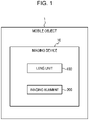
- the imaging device 10 illustrated in Fig. 1 includes a lens unit 100 and an imaging element 200.
- the lens unit 100 includes a plurality of optical members, such as lenses.
- the lenses included in the lens unit 100 may, for example, be lenses having a wide angle of view, such as fisheye lenses.
- the lens unit 100 focuses a subject image on a light-receiving surface of the imaging element 200.
- the imaging element 200 includes, for example, a charge coupled device (CCD) image sensor or a complementary metal-oxide semiconductor (CMOS) image sensor.
- CCD charge coupled device
- CMOS complementary metal-oxide semiconductor
- a plurality of pixels (light receiving elements) are arranged on the light-receiving surface of the imaging element 200.
- the imaging element 200 captures the subject image focused on the light-receiving surface and creates a captured image.
- the imaging device 10 may output the captured image to an external device mounted in the mobile object 1.
- the external device may be, for example, an electronic control unit (ECU), a display, or a navigation device.
- the imaging device 10 may have a function of performing a predetermined image process, such as a white balance adjustment process, an exposure adjustment process, or a gamma correction process, on the captured image.
- the imaging device 10 is a monocular camera including a single imaging system composed of the lens unit 100 and the imaging element 200.
- the imaging device 10 is not limited to this.
- the imaging device 10 may instead be a stereo camera that includes a plurality of imaging systems that cooperate with each other to capture images of a target from different visual points.
- two lens units 100 for example, are disposed next to each other with an interval therebetween in a vehicle width direction of the mobile object 1 so that optical axes thereof are parallel to each other. Accordingly, the imaging systems capture images of substantially the same area from different visual points.
- the imaging device 10 may be fixed to, for example, a front bumper, a fender grille, a side fender, a light module, a hood, etc., of a vehicle.
- the structure of the imaging device 10 will now be described with reference to Fig. 2 .
- the imaging device 10 includes the lens unit 100, the imaging element 200, and an imaging substrate 201 on which a housing 300 and the imaging element 200 are mounted.
- the lens unit 100 includes a plurality of lenses 101a to 101e, a lens barrel 110, spacing rings 120a to 120d, and a retainer 130.
- the lenses 101a to 101e will be referred to as lenses 101 when they are not distinguished from each other.
- the spacing rings 120a to 120d will be referred to as spacing rings 120 when they are not distinguished from each other.
- the lenses 101a to 101e are arranged in the direction of an optical axis OA.
- the lenses 101a to 101e are arranged such that optical axes thereof coincide with the optical axis OA.
- a direction orthogonal to the optical axis direction in a plan view viewed in the optical axis direction will be referred to as a radial direction
- a direction that circulates around the optical axis direction will be referred to as a circumferential direction.
- the lenses 101 are made of a glass or a resin, such as polycarbonate (PC), cyclo-olefin polymer (COP), cyclo-olefin copolymer (COC), or poly(methyl methacrylate) (PMMA).
- PC polycarbonate
- COP cyclo-olefin polymer
- COC cyclo-olefin copolymer
- PMMA poly(methyl methacrylate)
- the lens barrel 110 is a cylindrical member having an opening 111 larger than the lenses 101a to 105e.
- the lens barrel 110 has an internal space in which the lenses 101 are contained and held. More specifically, the lens barrel 110 contains the lenses 101a to 101e such that the lens 101e, the lens 101d, the lens 101c, the lens 101b, and the lens 101a are arranged in that order from the opening 111. Thus, among the lenses 101, the lens 101e is closest to the opening 111. In addition, among the lenses 101, the lens 101a is at a side farthest from the opening 111 (hereinafter referred to as "bottom").
- the lens barrel 110 contains the lenses 101 such that the central axis of the lens barrel 110 coincides with the optical axis OA.
- the lens barrel 110 may be made of, for example, aluminum or stainless steel.
- the lens barrel 110 has a thread groove 114 in the outer periphery thereof.
- the housing 300 has a threaded portion (thread crest) 301 configured to engage with the thread groove 114 in the outer periphery of the lens barrel 110.
- the imaging device 10 includes an adhesive member 151 positioned between the thread groove 114 in the outer periphery of the lens barrel 110 and the threaded portion 301 of the housing 300. More specifically, the lens barrel 110 is accommodated in the housing 300 and screw fastened to the housing 300 at a first fixing section 150.
- the threaded portion 301 is formed on an inner peripheral surface of an accommodation space of the housing 300 that accommodates the lens barrel 110 at a position corresponding to the first fixing section 150.
- a thread groove 114 that engages with the threaded portion 301 is formed in an outer peripheral surface of the lens barrel 110 at a position corresponding to the first fixing section 150.
- the adhesive member 151 is applied to at least one of the threaded portion 301 on the inner peripheral surface of the accommodation space of the housing 300 and the thread groove 114 in the outer peripheral surface of the lens barrel 110.
- the adhesive member 151 is, for example, an adhesive having a small coefficient of linear expansion.
- the lens barrel 110 By inserting the lens barrel 110 into the accommodation space of the housing 300 while rotating the lens barrel 110 in the circumferential direction, the lens barrel 110 can be screwed into the accommodation space of the housing 300 such that the threaded portion 301 on the inner peripheral surface of the accommodation space of the housing 300 engages with the thread groove 114 in the outer peripheral surface of the lens barrel 110.
- the lens barrel 110 and the housing 300 are fixed by adhesion while the position of the lens barrel 110 is adjusted such that the lenses 101 focus the subject image on the light-receiving surface of the imaging element 200.
- the adhesive member 151 is a thermosetting adhesive
- the thermosetting adhesive is cured to fix the lens barrel 110 and the housing 300.
- a filter 202 is positioned between the lens unit 100 and the imaging element 200.
- the filter 202 may be, for example, an ultraviolet (UV)/infrared (IR) cut filter, a color filter, or a low-pass filter.
- the filter 202 may instead be a glass plate having an antireflection (AR) coating.
- the filter 202 is supported by a support portion 203.
- the support portion 203 supports the filter 202.
- the support portion 203 has a sealing structure so that no foreign matter adheres to the light-receiving surface of the imaging element 200.
- a first projecting portion 112 that projects radially outward is formed on the outer peripheral surface of the lens barrel 110.
- the first projecting portion 112 is in contact with the housing 300 with a wave washer 140 provided therebetween when the lens unit 100 is accommodated in the housing 300.
- the wave washer 140 is pressed and urged by the first projecting portion 112 of the lens barrel 110 in the direction in which the lens barrel 110 is inserted.
- the backlash can be reduced by placing the wave washer 140 that is pressed and urged between the first projecting portion 112 of the lens barrel 110 and the housing 300.
- a second projecting portion 113 that projects radially inward is provided on an inner peripheral surface of the lens barrel 110 at the bottom of the lens barrel 110.
- the second projecting portion 113 of the lens barrel 110 has an inner diameter less than the outer diameter of the lens 101a closest to the bottom. Accordingly, the second projecting portion 113 serves as a holder that holds the lens 101a.
- the spacing rings 120 are annular members having an outer diameter substantially equal to the inner diameter of the lens barrel 110 and an inner diameter substantially equal to the outer diameter of a lens portion of each lens 101 described below.
- the spacing rings 120 serve as holders that hold the lenses 101 in the lens barrel 110.
- the spacing rings 120 also serve as spacers that adjust the distances between the lenses 101 in the optical axis direction.
- the spacing ring 120a is positioned between an object-side surface (surface adjacent to the opening 111) of the lens 101a and an image-side surface (surface adjacent to the bottom) of the lens 101b.
- the spacing ring 120b is positioned between an object-side surface of the lens 101b and an image-side surface of the lens 101c.
- the spacing ring 120c is positioned on an object-side surface of the lens 101c.
- the spacing ring 120d is positioned between the spacing ring 120c and an image-side surface of the lens 101d.
- the lens 101e is positioned in contact with an object-side surface of the lens 101d. The intervals between the lenses 101 contained in the lens barrel 110 in the optical axis direction are adjusted by the spacing rings 120a to 120d.
- the lens barrel 110 has the opening 111 larger than the outer diameters of the lenses 101.
- the second projecting portion 113 which projects radially inward and which is capable of holding the lens 101a closest to the bottom, is provided on the inner peripheral surface of the lens barrel 110 at the bottom of the lens barrel 110. Accordingly, the lens 101a, the spacing ring 120a, the lens 101b, the spacing ring 120b, the lens 101c, the spacing ring 120c, the spacing ring 120d, the lens 101d, and the lens 101e are inserted into the lens barrel 110 through the opening 111 in that order.
- the retainer 130 which serves as a holding member, is in contact with the lens 101e, which is one of the lenses 101 that is closest to the opening 111, and thereby holds the lenses 101 from the side adjacent to the opening 111.
- the retainer 130 includes an outer peripheral portion 131 and a contact portion 132.
- the outer peripheral portion 131 is fixed to the outer peripheral surface of the lens barrel 110.
- the outer peripheral portion 131 is fixed to the outer peripheral surface of the lens barrel 110 at a second fixing section 160, which is closer to the opening 111 than the first projecting portion 112.
- the outer peripheral portion 131 is, for example, fixed by being screwed onto the lens barrel 110.
- a thread crest is formed on the outer peripheral surface of the lens barrel 110 at a position corresponding to the second fixing section 160.
- a thread groove that engages with the thread crest formed on the outer peripheral surface of the lens barrel 110 is formed in an inner peripheral surface of the outer peripheral portion 131 at a position corresponding to the second fixing section 160.
- the retainer 130 is fixed to the outer peripheral surface of the lens barrel 110 by pushing the retainer 130 into the housing 300 in the optical axis direction while rotating the retainer 130 in the circumferential direction.
- the contact portion 132 extends radially inward from an end portion of the outer peripheral portion 131 adjacent to the opening 111.
- the contact portion 132 is in contact with the lens 101e closest to the opening 111 and holds the lenses 101 in the optical axis direction.
- the imaging element 200 captures the subject image incident thereon through the lens 101.
- the housing 300 holds the imaging element 200.
- a rotational displacement caused by thermal expansion or contraction of the adhesive member 151 due to temperature variation will now be described with reference to Figs. 3A and 3B .
- the adhesive member 151 expands or contracts in response to temperature variation.
- the nominal diameter (outer diameter of the lens barrel 110) M is assumed to be 12 mm, and the amount of thermal expansion or contraction ⁇ g is assumed to be 0.0022 mm.
- the lens rotation angle ⁇ is 0.021 degrees. Accordingly, when the adhesive member 151 thermally expands or contracts, the lens unit 100 may tilt by 0.021 degrees at a maximum.
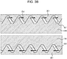
- Fig. 3B is an enlarged view of the first fixing section 150. Assuming the worst case, a screw clearance in a state of screw abutment illustrated in Fig. 3B is used in the calculation. However, such a case is unlikely because suppression of the rotation occurs in practice.
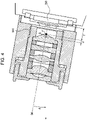
- a distance f from a sensor surface of the imaging element 200 to an image-side principal point P is 4.28 mm in terms of an air conversion distance.
- a screw fastening position of the first fixing section 150 (position at which the lens barrel 110 and the housing 300 are fixed by adhesion) may be regarded as a rotation center Q of the lens unit 100.
- the rotation center is ideally at the image-side principal point P. This is because the focus position does not change when the image-side principal point P is the rotation center.
- a distance d between the image-side principal point P and the rotation center Q is 1.628 mm.
- the lens rotation angle ⁇ due to temperature variation is 0.021 degrees.
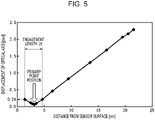
- Fig. 5 shows the displacement of the optical axis caused when the lens rotation angle ⁇ due to temperature variation of the adhesive member 151 is 0.021 degrees.
- the horizontal axis represents the distance from the sensor surface of the imaging element 200 to the rotation center Q.
- the vertical axis represents the displacement of the optical axis.
- the thread groove 114 formed in the outer periphery of the lens barrel 110 at the first fixing section 150 is provided in a range including a position at which a principal plane of the optical system including the lenses 101 (plane extending through the image-side principal point P and perpendicular to the optical axis OA) crosses the outer periphery of the lens barrel 110.
- the image-side surface of the lens 101a which is one of the lenses 101 that is closest to the imaging element 200, may be positioned in a range corresponding to a range in which the thread groove 114 in the outer periphery of the lens barrel 110 and the threaded portion 301 of the housing 300 engage with each other along the optical axis OA of the lenses 101.
- the rotation center Q may be positioned close to the image-side principal point P, and the displacement of the optical axis can be reduced. Referring to the graph of Fig. 5 , even when, for example, the distance d between the image-side principal point P and the rotation center Q is 1.628 mm as described above, the displacement of the optical axis is as small as 0.24 pixels.
- the displacement of the optical axis is calculated as 0.034 pixels based on the mean square of two displacements of 0.24 pixels.
- a method for manufacturing the imaging device 10 will now be described with reference to Fig. 6 .
- step S101 the lens barrel 110 in which the lenses 101 are held and that has the thread groove 114 in the cylindrical outer periphery thereof is prepared.
- the housing 300 having the threaded portion 301 configured to engage with the thread groove 114 is prepared.
- the thread groove 114 is provided at a position at which the principal plane of the optical system including the lenses 101 crosses the outer periphery of the lens barrel 110.
- step S102 the adhesive member 151 is applied to at least one of the thread groove 114 and the threaded portion 301.
- step S103 the thread groove 114 and the threaded portion 301 are engaged with each other and the focus position is adjusted.
- the image-side surface of the lens 101a closest to the imaging element 200 is positioned in the range corresponding to the range in which the thread groove 114 in the outer periphery of the lens barrel 110 and the threaded portion 301 of the housing 300 engage with each other along the optical axis OA of the lenses 101.
- step S104 the adhesive member 151 is cured to fix the positions of the lens barrel 110 and the housing 300.
- the imaging device 10 includes the lens barrel 110 in which the lenses 101 are held and that has the thread groove 114 in the cylindrical outer periphery thereof.
- the imaging device 10 also includes the housing 300 that holds the imaging element 200 and that has the threaded portion 301 configured to engage with the thread groove 114 in the outer periphery of the lens barrel 110. Accordingly, the lens barrel 110 can be inserted into the accommodation space in the housing 300 such that the threaded portion 301 and the thread groove 114 engage with each other. Therefore, focus adjustment can be facilitated.
- the thread groove 114 in the outer periphery of the lens barrel 110 is provided in a range including the position at which the principal plane of the optical system including the lenses 101 crosses the outer periphery of the lens barrel 110.
- the image-side surface of the lens 101a that is closest to the imaging element 200 may be positioned in the range corresponding to the range in which the thread groove 114 and the threaded portion 301 engage with each other along the optical axis OA of the lenses 101.
- the rotation center Q may be positioned close to the image-side principal point P, so that the displacement of the optical axis can be reduced.
- Terms such as “first” and “second” in the present disclosure are identifiers for distinguishing components.
- Components distinguished by terms such as “first” and “second” in the present disclosure may have their numbers interchanged with each other.
- the identifier “first” of the first optical member and the identifier “second” of the second optical member may be interchanged with each other.
- the identifiers are interchanged with each other simultaneously.
- the components are distinguishable even after their identifiers are interchanged.
- the identifiers may be omitted.
- Components whose identifiers are omitted are distinguished by reference signs. Description of identifiers such as “first” and “second” in the present disclosure alone should not be used for interpretation of the order of components or as basis for assuming that identifiers of smaller numbers are present. Reference Signs List
Landscapes
- Physics & Mathematics (AREA)
- General Physics & Mathematics (AREA)
- Optics & Photonics (AREA)
- Engineering & Computer Science (AREA)
- Multimedia (AREA)
- Signal Processing (AREA)
- Lens Barrels (AREA)
- Studio Devices (AREA)
- Camera Bodies And Camera Details Or Accessories (AREA)
- Mounting And Adjusting Of Optical Elements (AREA)
Abstract
Description
- The present application claims priority from
Japanese Patent Application No. 2019-183285 filed in the Japan Patent Office on October 3, 2019 - The present disclosure relates to an imaging device, a mobile object, and a method for manufacturing an imaging device.
-
PTL 1 discloses a method for performing focus adjustment based on a thickness of a spacer inserted between an attachment reference surface for an imaging element and the imaging element. - PTL 1:
Japanese Unexamined Patent Application Publication No. 2000-9982 - An imaging device according to the present disclosure includes a lens barrel in which a plurality of lenses are held and that has a thread groove in a cylindrical outer periphery thereof; an imaging element that captures a subject image incident on the imaging element through the lenses; a housing that holds the imaging element and that includes a threaded portion configured to engage with the thread groove in the outer periphery of the lens barrel; and an adhesive member positioned between the thread groove in the outer periphery of the lens barrel and the threaded portion of the housing. The thread groove is provided in a range including a position at which a principal plane of an optical system including the plurality of lenses crosses the outer periphery of the lens barrel.
- A mobile object according to the present disclosure has the above-described imaging device mounted therein.
- A method for manufacturing an imaging device according to the present disclosure includes preparing a lens barrel in which a plurality of lenses are held and that has a thread groove in a cylindrical outer periphery thereof, and a housing including a threaded portion configured to engage with the thread groove in the outer periphery of the lens barrel; applying an adhesive member to at least one of the thread groove and the threaded portion; adjusting a focus position by engaging the thread groove and the threaded portion with each other; and fixing positions of the lens barrel and the housing by curing the adhesive member. The thread groove is provided at a position at which a principal plane of an optical system including the plurality of lenses crosses the outer periphery of the lens barrel.
-
- [
Fig. 1] Fig. 1 is a block diagram illustrating an exemplary configuration of an imaging device according to an embodiment. - [
Fig. 2] Fig. 2 is a sectional view illustrating an exemplary configuration of the imaging device according to the embodiment. - [
Fig. 3A] Fig. 3A illustrates a rotational displacement caused by temperature variation in the imaging device according to the embodiment. - [
Fig. 3B] Fig. 3B is a diagram used to describe a rotational displacement caused by temperature variation in the imaging device according to the embodiment. - [
Fig. 4] Fig. 4 illustrates a rotation center of the imaging device according to the embodiment. - [
Fig. 5] Fig. 5 is a graph showing the displacement of an optical axis in the imaging device according to the embodiment. - [
Fig. 6] Fig. 6 is a flowchart of a method for manufacturing an imaging device according to the embodiment. Description of Embodiments - According to the method disclosed in
PTL 1, when a substrate on which the imaging element is mounted and the spacer are fastened with screws to the attachment reference surface, a focus position may vary depending on the screw fastening force. In addition, an optical axis may tilt unless screws are fastened with equal force. Therefore, assembly needs to be carefully performed. An embodiment of the present disclosure provides an imaging device, a mobile object, and a method for manufacturing the imaging device with which focus adjustment can be facilitated and the displacement of the optical axis can be reduced. - An embodiment of the present disclosure will now be described with reference to the drawings. In the drawings, the same reference signs denote the same or similar components. The drawings referred to in the following description are schematic. Dimensional ratios in the drawings, for example, do not necessarily coincide with actual dimensional ratios.
- As illustrated in
Fig. 1 , animaging device 10 according to an embodiment of the present disclosure may be mounted in amobile object 1. When theimaging device 10 is mounted in themobile object 1, theimaging device 10 may capture an image of a subject in a space around themobile object 1. The image captured by theimaging device 10 may be used, for example, to detect an object (human, vehicle, etc.) in the space around themobile object 1. - Examples of the
mobile object 1 may include a vehicle and an aircraft. Examples of the vehicle may include an automobile, an industrial vehicle, a railroad vehicle, a daily use vehicle, and a fixed-wing airplane that runs on a runway. Examples of the automobile may include a passenger vehicle, a truck, a bus, a two-wheel vehicle, and a trolley bus. Examples of the industrial vehicle may include an industrial vehicle for agriculture and an industrial vehicle for construction. Examples of the industrial vehicle may include a forklift and a golf cart. Examples of the industrial vehicle for agriculture may include a tractor, a cultivator, a transplanter, a binder, a combine, and a mower. Examples of the industrial vehicle for construction may include a bulldozer, a scraper, an excavator, a crane truck, a dump truck, and a road roller. The vehicle may be a vehicle driven by human force. The categories of the vehicle are not limited to those described above. For example, the automobile may be an industrial vehicle capable of running on a road. The same vehicle may belong to two or more categories. Examples of the aircraft may include a fixed-wing airplane and a rotary wing aircraft. - The
imaging device 10 illustrated inFig. 1 includes alens unit 100 and animaging element 200. - The
lens unit 100 includes a plurality of optical members, such as lenses. The lenses included in thelens unit 100 may, for example, be lenses having a wide angle of view, such as fisheye lenses. Thelens unit 100 focuses a subject image on a light-receiving surface of theimaging element 200. - The
imaging element 200 includes, for example, a charge coupled device (CCD) image sensor or a complementary metal-oxide semiconductor (CMOS) image sensor. A plurality of pixels (light receiving elements) are arranged on the light-receiving surface of theimaging element 200. Theimaging element 200 captures the subject image focused on the light-receiving surface and creates a captured image. Theimaging device 10 may output the captured image to an external device mounted in themobile object 1. The external device may be, for example, an electronic control unit (ECU), a display, or a navigation device. Theimaging device 10 may have a function of performing a predetermined image process, such as a white balance adjustment process, an exposure adjustment process, or a gamma correction process, on the captured image. - In the example illustrated in
Fig. 1 , theimaging device 10 is a monocular camera including a single imaging system composed of thelens unit 100 and theimaging element 200. However, theimaging device 10 is not limited to this. Theimaging device 10 may instead be a stereo camera that includes a plurality of imaging systems that cooperate with each other to capture images of a target from different visual points. When theimaging device 10 is a stereo camera, twolens units 100, for example, are disposed next to each other with an interval therebetween in a vehicle width direction of themobile object 1 so that optical axes thereof are parallel to each other. Accordingly, the imaging systems capture images of substantially the same area from different visual points. Theimaging device 10 may be fixed to, for example, a front bumper, a fender grille, a side fender, a light module, a hood, etc., of a vehicle. - The structure of the
imaging device 10 will now be described with reference toFig. 2 . - As illustrated in
Fig. 2 , theimaging device 10 includes thelens unit 100, theimaging element 200, and animaging substrate 201 on which ahousing 300 and theimaging element 200 are mounted. - The
lens unit 100 includes a plurality oflenses 101a to 101e, alens barrel 110,spacing rings 120a to 120d, and aretainer 130. In the following description, thelenses 101a to 101e will be referred to aslenses 101 when they are not distinguished from each other. Also, thespacing rings 120a to 120d will be referred to as spacing rings 120 when they are not distinguished from each other. - The
lenses 101a to 101e are arranged in the direction of an optical axis OA. In other words, thelenses 101a to 101e are arranged such that optical axes thereof coincide with the optical axis OA. In the following direction, a direction orthogonal to the optical axis direction in a plan view viewed in the optical axis direction will be referred to as a radial direction, and a direction that circulates around the optical axis direction will be referred to as a circumferential direction. - The
lenses 101 are made of a glass or a resin, such as polycarbonate (PC), cyclo-olefin polymer (COP), cyclo-olefin copolymer (COC), or poly(methyl methacrylate) (PMMA). - The
lens barrel 110 is a cylindrical member having anopening 111 larger than thelenses 101a to 105e. Thelens barrel 110 has an internal space in which thelenses 101 are contained and held. More specifically, thelens barrel 110 contains thelenses 101a to 101e such that thelens 101e, thelens 101d, thelens 101c, thelens 101b, and thelens 101a are arranged in that order from theopening 111. Thus, among thelenses 101, thelens 101e is closest to theopening 111. In addition, among thelenses 101, thelens 101a is at a side farthest from the opening 111 (hereinafter referred to as "bottom"). Thelens barrel 110 contains thelenses 101 such that the central axis of thelens barrel 110 coincides with the optical axis OA. Thelens barrel 110 may be made of, for example, aluminum or stainless steel. - The
lens barrel 110 has athread groove 114 in the outer periphery thereof. Thehousing 300 has a threaded portion (thread crest) 301 configured to engage with thethread groove 114 in the outer periphery of thelens barrel 110. Theimaging device 10 includes anadhesive member 151 positioned between thethread groove 114 in the outer periphery of thelens barrel 110 and the threadedportion 301 of thehousing 300. More specifically, thelens barrel 110 is accommodated in thehousing 300 and screw fastened to thehousing 300 at afirst fixing section 150. The threadedportion 301 is formed on an inner peripheral surface of an accommodation space of thehousing 300 that accommodates thelens barrel 110 at a position corresponding to thefirst fixing section 150. In addition, athread groove 114 that engages with the threadedportion 301 is formed in an outer peripheral surface of thelens barrel 110 at a position corresponding to thefirst fixing section 150. Theadhesive member 151 is applied to at least one of the threadedportion 301 on the inner peripheral surface of the accommodation space of thehousing 300 and thethread groove 114 in the outer peripheral surface of thelens barrel 110. Theadhesive member 151 is, for example, an adhesive having a small coefficient of linear expansion. - By inserting the
lens barrel 110 into the accommodation space of thehousing 300 while rotating thelens barrel 110 in the circumferential direction, thelens barrel 110 can be screwed into the accommodation space of thehousing 300 such that the threadedportion 301 on the inner peripheral surface of the accommodation space of thehousing 300 engages with thethread groove 114 in the outer peripheral surface of thelens barrel 110. Thelens barrel 110 and thehousing 300 are fixed by adhesion while the position of thelens barrel 110 is adjusted such that thelenses 101 focus the subject image on the light-receiving surface of theimaging element 200. When theadhesive member 151 is a thermosetting adhesive, the thermosetting adhesive is cured to fix thelens barrel 110 and thehousing 300. - A
filter 202 is positioned between thelens unit 100 and theimaging element 200. Thefilter 202 may be, for example, an ultraviolet (UV)/infrared (IR) cut filter, a color filter, or a low-pass filter. Thefilter 202 may instead be a glass plate having an antireflection (AR) coating. Thefilter 202 is supported by asupport portion 203. Thesupport portion 203 supports thefilter 202. Thesupport portion 203 has a sealing structure so that no foreign matter adheres to the light-receiving surface of theimaging element 200. - A first projecting
portion 112 that projects radially outward is formed on the outer peripheral surface of thelens barrel 110. The first projectingportion 112 is in contact with thehousing 300 with awave washer 140 provided therebetween when thelens unit 100 is accommodated in thehousing 300. When thelens barrel 110 is inserted into the accommodation space of thehousing 300, thewave washer 140 is pressed and urged by the first projectingportion 112 of thelens barrel 110 in the direction in which thelens barrel 110 is inserted. When thelens barrel 110 is rotated for position adjustment, it may be difficult to perform fine adjustment due to backlash. The backlash can be reduced by placing thewave washer 140 that is pressed and urged between the first projectingportion 112 of thelens barrel 110 and thehousing 300. - A second projecting
portion 113 that projects radially inward is provided on an inner peripheral surface of thelens barrel 110 at the bottom of thelens barrel 110. The second projectingportion 113 of thelens barrel 110 has an inner diameter less than the outer diameter of thelens 101a closest to the bottom. Accordingly, the second projectingportion 113 serves as a holder that holds thelens 101a. - The spacing rings 120 are annular members having an outer diameter substantially equal to the inner diameter of the
lens barrel 110 and an inner diameter substantially equal to the outer diameter of a lens portion of eachlens 101 described below. The spacing rings 120 serve as holders that hold thelenses 101 in thelens barrel 110. The spacing rings 120 also serve as spacers that adjust the distances between thelenses 101 in the optical axis direction. - The
spacing ring 120a is positioned between an object-side surface (surface adjacent to the opening 111) of thelens 101a and an image-side surface (surface adjacent to the bottom) of thelens 101b. Thespacing ring 120b is positioned between an object-side surface of thelens 101b and an image-side surface of thelens 101c. The spacing ring 120c is positioned on an object-side surface of thelens 101c. Thespacing ring 120d is positioned between the spacing ring 120c and an image-side surface of thelens 101d. Thelens 101e is positioned in contact with an object-side surface of thelens 101d. The intervals between thelenses 101 contained in thelens barrel 110 in the optical axis direction are adjusted by thespacing rings 120a to 120d. - As described above, the
lens barrel 110 has theopening 111 larger than the outer diameters of thelenses 101. In addition, the second projectingportion 113, which projects radially inward and which is capable of holding thelens 101a closest to the bottom, is provided on the inner peripheral surface of thelens barrel 110 at the bottom of thelens barrel 110. Accordingly, thelens 101a, thespacing ring 120a, thelens 101b, thespacing ring 120b, thelens 101c, the spacing ring 120c, thespacing ring 120d, thelens 101d, and thelens 101e are inserted into thelens barrel 110 through theopening 111 in that order. - The
retainer 130, which serves as a holding member, is in contact with thelens 101e, which is one of thelenses 101 that is closest to theopening 111, and thereby holds thelenses 101 from the side adjacent to theopening 111. Theretainer 130 includes an outerperipheral portion 131 and acontact portion 132. - The outer
peripheral portion 131 is fixed to the outer peripheral surface of thelens barrel 110. For example, as illustrated inFig. 2 , the outerperipheral portion 131 is fixed to the outer peripheral surface of thelens barrel 110 at asecond fixing section 160, which is closer to theopening 111 than the first projectingportion 112. The outerperipheral portion 131 is, for example, fixed by being screwed onto thelens barrel 110. In this case, for example, a thread crest is formed on the outer peripheral surface of thelens barrel 110 at a position corresponding to thesecond fixing section 160. In addition, a thread groove that engages with the thread crest formed on the outer peripheral surface of thelens barrel 110 is formed in an inner peripheral surface of the outerperipheral portion 131 at a position corresponding to thesecond fixing section 160. Theretainer 130 is fixed to the outer peripheral surface of thelens barrel 110 by pushing theretainer 130 into thehousing 300 in the optical axis direction while rotating theretainer 130 in the circumferential direction. - The
contact portion 132 extends radially inward from an end portion of the outerperipheral portion 131 adjacent to theopening 111. When theretainer 130 is fixed to the outer peripheral surface of thelens barrel 110, thecontact portion 132 is in contact with thelens 101e closest to theopening 111 and holds thelenses 101 in the optical axis direction. - The
imaging element 200 captures the subject image incident thereon through thelens 101. Thehousing 300 holds theimaging element 200. - A rotational displacement caused by thermal expansion or contraction of the
adhesive member 151 due to temperature variation will now be described with reference toFigs. 3A and3B . Theadhesive member 151 expands or contracts in response to temperature variation. An amount of rotational displacement (lens rotation angle) θ of thelens unit 100 due to temperature variation may be determined by using an amount of thermal expansion or contraction Δg of theadhesive member 151 and a nominal screw diameter M as in Expression (1) given below.
[Math. 1]
- In the present embodiment, the nominal diameter (outer diameter of the lens barrel 110) M is assumed to be 12 mm, and the amount of thermal expansion or contraction Δg is assumed to be 0.0022 mm. In this case, according to Expression (1), the lens rotation angle θ is 0.021 degrees. Accordingly, when the
adhesive member 151 thermally expands or contracts, thelens unit 100 may tilt by 0.021 degrees at a maximum.Fig. 3B is an enlarged view of thefirst fixing section 150. Assuming the worst case, a screw clearance in a state of screw abutment illustrated inFig. 3B is used in the calculation. However, such a case is unlikely because suppression of the rotation occurs in practice. - Referring to
Fig. 4 , in the present embodiment, a distance f from a sensor surface of theimaging element 200 to an image-side principal point P is 4.28 mm in terms of an air conversion distance. A screw fastening position of the first fixing section 150 (position at which thelens barrel 110 and thehousing 300 are fixed by adhesion) may be regarded as a rotation center Q of thelens unit 100. The rotation center is ideally at the image-side principal point P. This is because the focus position does not change when the image-side principal point P is the rotation center. Assuming the worst case where the screw fastening position of thefirst fixing section 150 is at an end of a screw engagement portion, a distance d between the image-side principal point P and the rotation center Q is 1.628 mm. Assume that the lens rotation angle θ due to temperature variation is 0.021 degrees. -
Fig. 5 shows the displacement of the optical axis caused when the lens rotation angle θ due to temperature variation of theadhesive member 151 is 0.021 degrees. The horizontal axis represents the distance from the sensor surface of theimaging element 200 to the rotation center Q. The vertical axis represents the displacement of the optical axis. As is clear fromFig. 5 , the displacement of the optical axis is small when the screw fastening position of the first fixing section 150 (that is, the rotation center Q) is close to the image-side principal point P. Therefore, as illustrated inFigs. 2 and4 , thethread groove 114 formed in the outer periphery of thelens barrel 110 at thefirst fixing section 150 is provided in a range including a position at which a principal plane of the optical system including the lenses 101 (plane extending through the image-side principal point P and perpendicular to the optical axis OA) crosses the outer periphery of thelens barrel 110. - For example, the image-side surface of the
lens 101a, which is one of thelenses 101 that is closest to theimaging element 200, may be positioned in a range corresponding to a range in which thethread groove 114 in the outer periphery of thelens barrel 110 and the threadedportion 301 of thehousing 300 engage with each other along the optical axis OA of thelenses 101. In such a case, the rotation center Q may be positioned close to the image-side principal point P, and the displacement of the optical axis can be reduced. Referring to the graph ofFig. 5 , even when, for example, the distance d between the image-side principal point P and the rotation center Q is 1.628 mm as described above, the displacement of the optical axis is as small as 0.24 pixels. When binocular lenses are used, the displacement of the optical axis is calculated as 0.034 pixels based on the mean square of two displacements of 0.24 pixels. - A method for manufacturing the
imaging device 10 will now be described with reference toFig. 6 . - In step S101, the
lens barrel 110 in which thelenses 101 are held and that has thethread groove 114 in the cylindrical outer periphery thereof is prepared. In addition, thehousing 300 having the threadedportion 301 configured to engage with thethread groove 114 is prepared. Thethread groove 114 is provided at a position at which the principal plane of the optical system including thelenses 101 crosses the outer periphery of thelens barrel 110. - In step S102, the
adhesive member 151 is applied to at least one of thethread groove 114 and the threadedportion 301. - In step S103, the
thread groove 114 and the threadedportion 301 are engaged with each other and the focus position is adjusted. The image-side surface of thelens 101a closest to theimaging element 200 is positioned in the range corresponding to the range in which thethread groove 114 in the outer periphery of thelens barrel 110 and the threadedportion 301 of thehousing 300 engage with each other along the optical axis OA of thelenses 101. - In step S104, the
adhesive member 151 is cured to fix the positions of thelens barrel 110 and thehousing 300. - As described above, according to the present embodiment, the
imaging device 10 includes thelens barrel 110 in which thelenses 101 are held and that has thethread groove 114 in the cylindrical outer periphery thereof. Theimaging device 10 also includes thehousing 300 that holds theimaging element 200 and that has the threadedportion 301 configured to engage with thethread groove 114 in the outer periphery of thelens barrel 110. Accordingly, thelens barrel 110 can be inserted into the accommodation space in thehousing 300 such that the threadedportion 301 and thethread groove 114 engage with each other. Therefore, focus adjustment can be facilitated. - In addition, in the present embodiment, the
thread groove 114 in the outer periphery of thelens barrel 110 is provided in a range including the position at which the principal plane of the optical system including thelenses 101 crosses the outer periphery of thelens barrel 110. In addition, the image-side surface of thelens 101a that is closest to theimaging element 200 may be positioned in the range corresponding to the range in which thethread groove 114 and the threadedportion 301 engage with each other along the optical axis OA of thelenses 101. According to the above-described structure, the rotation center Q may be positioned close to the image-side principal point P, so that the displacement of the optical axis can be reduced. - Although typical examples have been described in the embodiment, it is obvious to those skilled in the art that various alterations and replacements are possible within the spirit and scope of the present disclosure. Therefore, the present invention is not to be regarded as being limited to the above-described embodiment, and various modifications and alterations are possible without departing from the scope of the claims.
- Terms such as "first" and "second" in the present disclosure are identifiers for distinguishing components. Components distinguished by terms such as "first" and "second" in the present disclosure may have their numbers interchanged with each other. For example, the identifier "first" of the first optical member and the identifier "second" of the second optical member may be interchanged with each other. The identifiers are interchanged with each other simultaneously. The components are distinguishable even after their identifiers are interchanged. The identifiers may be omitted. Components whose identifiers are omitted are distinguished by reference signs. Description of identifiers such as "first" and "second" in the present disclosure alone should not be used for interpretation of the order of components or as basis for assuming that identifiers of smaller numbers are present. Reference Signs List
-
- 1
- mobile object
- 10
- imaging device
- 100
- lens unit
- 101, 101a, 101b, 101c, 101d, 101e
- lens
- 102
- lens portion
- 103
- flat portion
- 110
- lens barrel
- 111
- opening
- 112
- first projecting portion
- 113
- second projecting portion (holder)
- 114
- thread groove
- 120, 120a, 120b, 120c, 120d
- spacing ring (holder)
- 130
- retainer (holding member)
- 131
- outer peripheral portion
- 132
- holding portion
- 140
- wave washer
- 150
- first fixing section
- 151
- adhesive member
- 160
- second fixing section
- 200
- imaging element
- 201
- imaging substrate
- 202
- filter
- 203
- support portion
- 300
- housing
- 301
- threaded portion
Claims (4)
- An imaging device comprising:a lens barrel in which a plurality of lenses are held and that has a thread groove in a cylindrical outer periphery thereof;an imaging element that captures a subject image incident on the imaging element through the lenses;a housing that holds the imaging element and that includes a threaded portion configured to engage with the thread groove in the outer periphery of the lens barrel; andan adhesive member positioned between the thread groove in the outer periphery of the lens barrel and the threaded portion of the housing,wherein the thread groove is provided in a range including a position at which a principal plane of an optical system including the plurality of lenses crosses the outer periphery of the lens barrel.
- The imaging device according to Claim 1, wherein an image-side surface of one of the plurality of lenses that is closest to the imaging element is positioned in a range corresponding to a range in which the thread groove in the outer periphery of the lens barrel and the threaded portion of the housing engage with each other along an optical axis of the lenses.
- A mobile object in which the imaging device according to Claim 1 or 2 is mounted.
- A method for manufacturing an imaging device, the method comprising:preparing a lens barrel in which a plurality of lenses are held and that has a thread groove in a cylindrical outer periphery thereof, and a housing including a threaded portion configured to engage with the thread groove in the outer periphery of the lens barrel;applying an adhesive member to at least one of the thread groove and the threaded portion;adjusting a focus position by engaging the thread groove and the threaded portion with each other; andfixing positions of the lens barrel and the housing by curing the adhesive member,wherein the thread groove is provided at a position at which a principal plane of an optical system including the plurality of lenses crosses the outer periphery of the lens barrel.
Applications Claiming Priority (2)
| Application Number | Priority Date | Filing Date | Title |
|---|---|---|---|
| JP2019183285A JP7239435B2 (en) | 2019-10-03 | 2019-10-03 | IMAGING DEVICE, MOVING OBJECT, AND METHOD FOR MANUFACTURING IMAGING DEVICE |
| PCT/JP2020/037485 WO2021066118A1 (en) | 2019-10-03 | 2020-10-01 | Imaging device, moving body, and imaging device manufacturing method |
Publications (3)
| Publication Number | Publication Date |
|---|---|
| EP4040206A1 true EP4040206A1 (en) | 2022-08-10 |
| EP4040206A4 EP4040206A4 (en) | 2023-08-23 |
| EP4040206B1 EP4040206B1 (en) | 2025-04-30 |
Family
ID=75337076
Family Applications (1)
| Application Number | Title | Priority Date | Filing Date |
|---|---|---|---|
| EP20872864.2A Active EP4040206B1 (en) | 2019-10-03 | 2020-10-01 | IMAGING DEVICE, MOVABLE BODY AND METHOD FOR MANUFACTURING AN IMAGING DEVICE |
Country Status (5)
| Country | Link |
|---|---|
| US (1) | US20220377214A1 (en) |
| EP (1) | EP4040206B1 (en) |
| JP (1) | JP7239435B2 (en) |
| CN (1) | CN114556178A (en) |
| WO (1) | WO2021066118A1 (en) |
Cited By (1)
| Publication number | Priority date | Publication date | Assignee | Title |
|---|---|---|---|---|
| EP4047403A4 (en) * | 2019-10-16 | 2023-11-22 | Kyocera Corporation | Lens unit, imaging device, and mobile object |
Families Citing this family (5)
| Publication number | Priority date | Publication date | Assignee | Title |
|---|---|---|---|---|
| CN214954298U (en) * | 2021-05-19 | 2021-11-30 | 深圳市绎立锐光科技开发有限公司 | Lens shell, lens module and light source system |
| US12130495B1 (en) * | 2022-04-15 | 2024-10-29 | Apple Inc. | Flangeless optical assembly for receiving glue dispense |
| CN114994855B (en) * | 2022-05-30 | 2024-01-23 | 信利光电股份有限公司 | Camera assembling process and system |
| JP2024147053A (en) * | 2023-04-03 | 2024-10-16 | ニデックインスツルメンツ株式会社 | Lens unit and lens centering method |
| CN120315116B (en) * | 2025-05-15 | 2026-02-17 | 广州长步道光学科技有限公司 | Lens device with adjustable flange distance |
Family Cites Families (14)
| Publication number | Priority date | Publication date | Assignee | Title |
|---|---|---|---|---|
| JP4017752B2 (en) | 1998-06-26 | 2007-12-05 | ペンタックス株式会社 | Focus adjustment method when assembling the taking lens |
| EP1471730A1 (en) * | 2003-03-31 | 2004-10-27 | Dialog Semiconductor GmbH | Miniature camera module |
| US20060056077A1 (en) * | 2004-09-15 | 2006-03-16 | Donal Johnston | Method for assembling a self-adjusting lens mount for automated assembly of vehicle sensors |
| JP4962194B2 (en) * | 2007-08-02 | 2012-06-27 | 富士通株式会社 | Image input module adjustment apparatus and image input module adjustment method |
| JP2009229589A (en) | 2008-03-19 | 2009-10-08 | Hitachi Maxell Ltd | Lens unit, camera module, and die |
| JP5326530B2 (en) * | 2008-12-03 | 2013-10-30 | パナソニック株式会社 | Screw parts and imaging device |
| JP5250575B2 (en) | 2010-02-17 | 2013-07-31 | 日立オートモティブシステムズ株式会社 | Camera device |
| JP2013198083A (en) | 2012-03-22 | 2013-09-30 | Sharp Corp | Camera module and manufacturing method of the same |
| US10996542B2 (en) * | 2012-12-31 | 2021-05-04 | Flir Systems, Inc. | Infrared imaging system shutter assembly with integrated thermister |
| JP6048325B2 (en) * | 2013-07-03 | 2016-12-21 | 株式会社デンソー | Imaging device |
| EP2942937B1 (en) * | 2014-05-07 | 2019-07-31 | Veoneer Sweden AB | Camera module for a motor vehicle and method of mounting a camera module |
| US10288985B2 (en) * | 2014-09-25 | 2019-05-14 | Nidec Copal Corporation | Imaging device, optical device, electronic device, vehicle, and production method for imaging device |
| JP6530215B2 (en) | 2015-03-26 | 2019-06-12 | マクセル株式会社 | Lens unit and camera module |
| JP2018018013A (en) * | 2016-07-29 | 2018-02-01 | 日本電産サンキョー株式会社 | Optical unit |
-
2019
- 2019-10-03 JP JP2019183285A patent/JP7239435B2/en active Active
-
2020
- 2020-10-01 US US17/754,444 patent/US20220377214A1/en not_active Abandoned
- 2020-10-01 WO PCT/JP2020/037485 patent/WO2021066118A1/en not_active Ceased
- 2020-10-01 CN CN202080069699.0A patent/CN114556178A/en active Pending
- 2020-10-01 EP EP20872864.2A patent/EP4040206B1/en active Active
Cited By (2)
| Publication number | Priority date | Publication date | Assignee | Title |
|---|---|---|---|---|
| EP4047403A4 (en) * | 2019-10-16 | 2023-11-22 | Kyocera Corporation | Lens unit, imaging device, and mobile object |
| US12292615B2 (en) | 2019-10-16 | 2025-05-06 | Kyocera Corporation | Lens unit, imaging device, and mobile object |
Also Published As
| Publication number | Publication date |
|---|---|
| EP4040206A4 (en) | 2023-08-23 |
| JP2021060468A (en) | 2021-04-15 |
| US20220377214A1 (en) | 2022-11-24 |
| CN114556178A (en) | 2022-05-27 |
| WO2021066118A1 (en) | 2021-04-08 |
| EP4040206B1 (en) | 2025-04-30 |
| JP7239435B2 (en) | 2023-03-14 |
Similar Documents
| Publication | Publication Date | Title |
|---|---|---|
| EP4040206B1 (en) | IMAGING DEVICE, MOVABLE BODY AND METHOD FOR MANUFACTURING AN IMAGING DEVICE | |
| KR102827675B1 (en) | Image Capturing Lens System | |
| US12271049B2 (en) | Vehicular camera with adhesive disposed between non-axially opposed surfaces of the lens barrel and PCB structure | |
| US8456769B2 (en) | Lens unit and vehicle-mounted infrared lens unit | |
| US12292615B2 (en) | Lens unit, imaging device, and mobile object | |
| US6597516B2 (en) | Lens frame structure for optical axis adjustment | |
| JP2020154123A (en) | Lens unit and manufacturing method of the same | |
| CN116848451A (en) | Optical systems and camera modules for vehicles | |
| US20240353649A1 (en) | Imaging lens system having retaining element and electronic device | |
| JP7588328B2 (en) | Manufacturing method of lens barrel, manufacturing method of holder, lens unit and camera module | |
| JP2019113753A (en) | Lens barrel, lens unit, and camera module | |
| US10893180B2 (en) | Imaging device | |
| JP7835539B2 (en) | Cemented lenses, lens units, camera modules, imaging systems, and mobile bodies | |
| JP2021033219A (en) | Lens unit and camera module | |
| JP6694287B2 (en) | Lens unit and camera module | |
| JP2020106730A (en) | Lens unit and camera module | |
| CN219370178U (en) | Shading piece, vehicle-mounted camera and vehicle | |
| JP7296826B2 (en) | Lens unit and camera module | |
| JP7827414B2 (en) | Lens unit, camera module, in-vehicle system and vehicle | |
| US20260036787A1 (en) | Imaging lens and electronic device | |
| US20250199295A1 (en) | Lens unit, camera module, in-vehicle system, and mobile body | |
| KR20240044829A (en) | Camera module and vehicle having the same | |
| KR20240037046A (en) | Camera module and vehicle having the same | |
| KR20240135298A (en) | Camera module and electronic device having the same | |
| CN120584320A (en) | Camera module and electronic device including the same |
Legal Events
| Date | Code | Title | Description |
|---|---|---|---|
| STAA | Information on the status of an ep patent application or granted ep patent |
Free format text: STATUS: THE INTERNATIONAL PUBLICATION HAS BEEN MADE |
|
| PUAI | Public reference made under article 153(3) epc to a published international application that has entered the european phase |
Free format text: ORIGINAL CODE: 0009012 |
|
| STAA | Information on the status of an ep patent application or granted ep patent |
Free format text: STATUS: REQUEST FOR EXAMINATION WAS MADE |
|
| 17P | Request for examination filed |
Effective date: 20220401 |
|
| AK | Designated contracting states |
Kind code of ref document: A1 Designated state(s): AL AT BE BG CH CY CZ DE DK EE ES FI FR GB GR HR HU IE IS IT LI LT LU LV MC MK MT NL NO PL PT RO RS SE SI SK SM TR |
|
| DAV | Request for validation of the european patent (deleted) | ||
| DAX | Request for extension of the european patent (deleted) | ||
| P01 | Opt-out of the competence of the unified patent court (upc) registered |
Effective date: 20230505 |
|
| A4 | Supplementary search report drawn up and despatched |
Effective date: 20230726 |
|
| RIC1 | Information provided on ipc code assigned before grant |
Ipc: H04N 23/55 20230101ALI20230720BHEP Ipc: G03B 43/00 20210101ALI20230720BHEP Ipc: G03B 17/12 20210101ALI20230720BHEP Ipc: G02B 7/04 20210101ALI20230720BHEP Ipc: G03B 3/02 20210101ALI20230720BHEP Ipc: H04N 23/57 20230101ALI20230720BHEP Ipc: G03B 17/02 20210101ALI20230720BHEP Ipc: G03B 15/00 20210101ALI20230720BHEP Ipc: G02B 7/02 20210101AFI20230720BHEP |
|
| GRAP | Despatch of communication of intention to grant a patent |
Free format text: ORIGINAL CODE: EPIDOSNIGR1 |
|
| STAA | Information on the status of an ep patent application or granted ep patent |
Free format text: STATUS: GRANT OF PATENT IS INTENDED |
|
| INTG | Intention to grant announced |
Effective date: 20241121 |
|
| RIN1 | Information on inventor provided before grant (corrected) |
Inventor name: HIRAISHI, AKIHIKO Inventor name: NAGOSHI, KEIICHI Inventor name: YAHAGI, HIROTO Inventor name: HIRAOKA, MICHIAKI Inventor name: OHARA, NAOTO |
|
| GRAS | Grant fee paid |
Free format text: ORIGINAL CODE: EPIDOSNIGR3 |
|
| GRAA | (expected) grant |
Free format text: ORIGINAL CODE: 0009210 |
|
| STAA | Information on the status of an ep patent application or granted ep patent |
Free format text: STATUS: THE PATENT HAS BEEN GRANTED |
|
| AK | Designated contracting states |
Kind code of ref document: B1 Designated state(s): AL AT BE BG CH CY CZ DE DK EE ES FI FR GB GR HR HU IE IS IT LI LT LU LV MC MK MT NL NO PL PT RO RS SE SI SK SM TR |
|
| REG | Reference to a national code |
Ref country code: CH Ref legal event code: EP Ref country code: GB Ref legal event code: FG4D |
|
| REG | Reference to a national code |
Ref country code: IE Ref legal event code: FG4D |
|
| REG | Reference to a national code |
Ref country code: DE Ref legal event code: R096 Ref document number: 602020050596 Country of ref document: DE |
|
| REG | Reference to a national code |
Ref country code: NL Ref legal event code: MP Effective date: 20250430 |
|
| REG | Reference to a national code |
Ref country code: AT Ref legal event code: MK05 Ref document number: 1790529 Country of ref document: AT Kind code of ref document: T Effective date: 20250430 |
|
| PG25 | Lapsed in a contracting state [announced via postgrant information from national office to epo] |
Ref country code: FI Free format text: LAPSE BECAUSE OF FAILURE TO SUBMIT A TRANSLATION OF THE DESCRIPTION OR TO PAY THE FEE WITHIN THE PRESCRIBED TIME-LIMIT Effective date: 20250430 Ref country code: PT Free format text: LAPSE BECAUSE OF FAILURE TO SUBMIT A TRANSLATION OF THE DESCRIPTION OR TO PAY THE FEE WITHIN THE PRESCRIBED TIME-LIMIT Effective date: 20250901 Ref country code: ES Free format text: LAPSE BECAUSE OF FAILURE TO SUBMIT A TRANSLATION OF THE DESCRIPTION OR TO PAY THE FEE WITHIN THE PRESCRIBED TIME-LIMIT Effective date: 20250430 |
|
| REG | Reference to a national code |
Ref country code: LT Ref legal event code: MG9D |
|
| PG25 | Lapsed in a contracting state [announced via postgrant information from national office to epo] |
Ref country code: GR Free format text: LAPSE BECAUSE OF FAILURE TO SUBMIT A TRANSLATION OF THE DESCRIPTION OR TO PAY THE FEE WITHIN THE PRESCRIBED TIME-LIMIT Effective date: 20250731 Ref country code: NO Free format text: LAPSE BECAUSE OF FAILURE TO SUBMIT A TRANSLATION OF THE DESCRIPTION OR TO PAY THE FEE WITHIN THE PRESCRIBED TIME-LIMIT Effective date: 20250730 |
|
| PG25 | Lapsed in a contracting state [announced via postgrant information from national office to epo] |
Ref country code: PL Free format text: LAPSE BECAUSE OF FAILURE TO SUBMIT A TRANSLATION OF THE DESCRIPTION OR TO PAY THE FEE WITHIN THE PRESCRIBED TIME-LIMIT Effective date: 20250430 Ref country code: NL Free format text: LAPSE BECAUSE OF FAILURE TO SUBMIT A TRANSLATION OF THE DESCRIPTION OR TO PAY THE FEE WITHIN THE PRESCRIBED TIME-LIMIT Effective date: 20250430 |
|
| PG25 | Lapsed in a contracting state [announced via postgrant information from national office to epo] |
Ref country code: BG Free format text: LAPSE BECAUSE OF FAILURE TO SUBMIT A TRANSLATION OF THE DESCRIPTION OR TO PAY THE FEE WITHIN THE PRESCRIBED TIME-LIMIT Effective date: 20250430 |
|
| PGFP | Annual fee paid to national office [announced via postgrant information from national office to epo] |
Ref country code: GB Payment date: 20250828 Year of fee payment: 6 |
|
| PG25 | Lapsed in a contracting state [announced via postgrant information from national office to epo] |
Ref country code: HR Free format text: LAPSE BECAUSE OF FAILURE TO SUBMIT A TRANSLATION OF THE DESCRIPTION OR TO PAY THE FEE WITHIN THE PRESCRIBED TIME-LIMIT Effective date: 20250430 |
|
| PG25 | Lapsed in a contracting state [announced via postgrant information from national office to epo] |
Ref country code: AT Free format text: LAPSE BECAUSE OF FAILURE TO SUBMIT A TRANSLATION OF THE DESCRIPTION OR TO PAY THE FEE WITHIN THE PRESCRIBED TIME-LIMIT Effective date: 20250430 |
|
| PGFP | Annual fee paid to national office [announced via postgrant information from national office to epo] |
Ref country code: FR Payment date: 20250908 Year of fee payment: 6 |
|
| PG25 | Lapsed in a contracting state [announced via postgrant information from national office to epo] |
Ref country code: RS Free format text: LAPSE BECAUSE OF FAILURE TO SUBMIT A TRANSLATION OF THE DESCRIPTION OR TO PAY THE FEE WITHIN THE PRESCRIBED TIME-LIMIT Effective date: 20250731 |
|
| PG25 | Lapsed in a contracting state [announced via postgrant information from national office to epo] |
Ref country code: IS Free format text: LAPSE BECAUSE OF FAILURE TO SUBMIT A TRANSLATION OF THE DESCRIPTION OR TO PAY THE FEE WITHIN THE PRESCRIBED TIME-LIMIT Effective date: 20250830 |
|
| PG25 | Lapsed in a contracting state [announced via postgrant information from national office to epo] |
Ref country code: LV Free format text: LAPSE BECAUSE OF FAILURE TO SUBMIT A TRANSLATION OF THE DESCRIPTION OR TO PAY THE FEE WITHIN THE PRESCRIBED TIME-LIMIT Effective date: 20250430 |
|
| PGFP | Annual fee paid to national office [announced via postgrant information from national office to epo] |
Ref country code: DE Payment date: 20250902 Year of fee payment: 6 |
|
| PG25 | Lapsed in a contracting state [announced via postgrant information from national office to epo] |
Ref country code: DK Free format text: LAPSE BECAUSE OF FAILURE TO SUBMIT A TRANSLATION OF THE DESCRIPTION OR TO PAY THE FEE WITHIN THE PRESCRIBED TIME-LIMIT Effective date: 20250430 Ref country code: SM Free format text: LAPSE BECAUSE OF FAILURE TO SUBMIT A TRANSLATION OF THE DESCRIPTION OR TO PAY THE FEE WITHIN THE PRESCRIBED TIME-LIMIT Effective date: 20250430 |
|
| PG25 | Lapsed in a contracting state [announced via postgrant information from national office to epo] |
Ref country code: CZ Free format text: LAPSE BECAUSE OF FAILURE TO SUBMIT A TRANSLATION OF THE DESCRIPTION OR TO PAY THE FEE WITHIN THE PRESCRIBED TIME-LIMIT Effective date: 20250430 |
|
| PG25 | Lapsed in a contracting state [announced via postgrant information from national office to epo] |
Ref country code: EE Free format text: LAPSE BECAUSE OF FAILURE TO SUBMIT A TRANSLATION OF THE DESCRIPTION OR TO PAY THE FEE WITHIN THE PRESCRIBED TIME-LIMIT Effective date: 20250430 |
|
| PG25 | Lapsed in a contracting state [announced via postgrant information from national office to epo] |
Ref country code: SK Free format text: LAPSE BECAUSE OF FAILURE TO SUBMIT A TRANSLATION OF THE DESCRIPTION OR TO PAY THE FEE WITHIN THE PRESCRIBED TIME-LIMIT Effective date: 20250430 |
|
| PG25 | Lapsed in a contracting state [announced via postgrant information from national office to epo] |
Ref country code: IT Free format text: LAPSE BECAUSE OF FAILURE TO SUBMIT A TRANSLATION OF THE DESCRIPTION OR TO PAY THE FEE WITHIN THE PRESCRIBED TIME-LIMIT Effective date: 20250430 |
|
| REG | Reference to a national code |
Ref country code: DE Ref legal event code: R097 Ref document number: 602020050596 Country of ref document: DE |
|
| PG25 | Lapsed in a contracting state [announced via postgrant information from national office to epo] |
Ref country code: RO Free format text: LAPSE BECAUSE OF FAILURE TO SUBMIT A TRANSLATION OF THE DESCRIPTION OR TO PAY THE FEE WITHIN THE PRESCRIBED TIME-LIMIT Effective date: 20250430 |
|
| PLBE | No opposition filed within time limit |
Free format text: ORIGINAL CODE: 0009261 |
|
| STAA | Information on the status of an ep patent application or granted ep patent |
Free format text: STATUS: NO OPPOSITION FILED WITHIN TIME LIMIT |
|
| REG | Reference to a national code |
Ref country code: CH Ref legal event code: L10 Free format text: ST27 STATUS EVENT CODE: U-0-0-L10-L00 (AS PROVIDED BY THE NATIONAL OFFICE) Effective date: 20260311 |
|
| 26N | No opposition filed |
Effective date: 20260202 |