EP4040122A1 - Radiation thermometer, temperature measurement method, and temperature measurement program - Google Patents
Radiation thermometer, temperature measurement method, and temperature measurement program Download PDFInfo
- Publication number
- EP4040122A1 EP4040122A1 EP20878512.1A EP20878512A EP4040122A1 EP 4040122 A1 EP4040122 A1 EP 4040122A1 EP 20878512 A EP20878512 A EP 20878512A EP 4040122 A1 EP4040122 A1 EP 4040122A1
- Authority
- EP
- European Patent Office
- Prior art keywords
- measurement
- target region
- temperature
- measurement target
- infrared
- Prior art date
- Legal status (The legal status is an assumption and is not a legal conclusion. Google has not performed a legal analysis and makes no representation as to the accuracy of the status listed.)
- Granted
Links
Images






Classifications
-
- G—PHYSICS
- G01—MEASURING; TESTING
- G01J—MEASUREMENT OF INTENSITY, VELOCITY, SPECTRAL CONTENT, POLARISATION, PHASE OR PULSE CHARACTERISTICS OF INFRARED, VISIBLE OR ULTRAVIOLET LIGHT; COLORIMETRY; RADIATION PYROMETRY
- G01J5/00—Radiation pyrometry, e.g. infrared or optical thermometry
- G01J5/02—Constructional details
- G01J5/08—Optical arrangements
- G01J5/0801—Means for wavelength selection or discrimination
- G01J5/0802—Optical filters
-
- G—PHYSICS
- G01—MEASURING; TESTING
- G01J—MEASUREMENT OF INTENSITY, VELOCITY, SPECTRAL CONTENT, POLARISATION, PHASE OR PULSE CHARACTERISTICS OF INFRARED, VISIBLE OR ULTRAVIOLET LIGHT; COLORIMETRY; RADIATION PYROMETRY
- G01J5/00—Radiation pyrometry, e.g. infrared or optical thermometry
- G01J5/10—Radiation pyrometry, e.g. infrared or optical thermometry using electric radiation detectors
- G01J5/12—Radiation pyrometry, e.g. infrared or optical thermometry using electric radiation detectors using thermoelectric elements, e.g. thermocouples
-
- G—PHYSICS
- G01—MEASURING; TESTING
- G01J—MEASUREMENT OF INTENSITY, VELOCITY, SPECTRAL CONTENT, POLARISATION, PHASE OR PULSE CHARACTERISTICS OF INFRARED, VISIBLE OR ULTRAVIOLET LIGHT; COLORIMETRY; RADIATION PYROMETRY
- G01J5/00—Radiation pyrometry, e.g. infrared or optical thermometry
- G01J5/02—Constructional details
- G01J5/07—Arrangements for adjusting the solid angle of collected radiation, e.g. adjusting or orienting field of view, tracking position or encoding angular position
-
- G—PHYSICS
- G01—MEASURING; TESTING
- G01J—MEASUREMENT OF INTENSITY, VELOCITY, SPECTRAL CONTENT, POLARISATION, PHASE OR PULSE CHARACTERISTICS OF INFRARED, VISIBLE OR ULTRAVIOLET LIGHT; COLORIMETRY; RADIATION PYROMETRY
- G01J5/00—Radiation pyrometry, e.g. infrared or optical thermometry
- G01J5/02—Constructional details
- G01J5/08—Optical arrangements
- G01J5/0831—Masks; Aperture plates; Spatial light modulators
-
- G—PHYSICS
- G01—MEASURING; TESTING
- G01J—MEASUREMENT OF INTENSITY, VELOCITY, SPECTRAL CONTENT, POLARISATION, PHASE OR PULSE CHARACTERISTICS OF INFRARED, VISIBLE OR ULTRAVIOLET LIGHT; COLORIMETRY; RADIATION PYROMETRY
- G01J5/00—Radiation pyrometry, e.g. infrared or optical thermometry
- G01J5/02—Constructional details
- G01J5/08—Optical arrangements
- G01J5/0871—Beam switching arrangements; Photodetection involving different fields of view for a single detector
-
- G—PHYSICS
- G01—MEASURING; TESTING
- G01J—MEASUREMENT OF INTENSITY, VELOCITY, SPECTRAL CONTENT, POLARISATION, PHASE OR PULSE CHARACTERISTICS OF INFRARED, VISIBLE OR ULTRAVIOLET LIGHT; COLORIMETRY; RADIATION PYROMETRY
- G01J5/00—Radiation pyrometry, e.g. infrared or optical thermometry
- G01J5/80—Calibration
Definitions
- the present invention relates to a non-contact radiation thermometer or the like that receives infrared rays emitted from a measurement target region by an infrared sensor (e.g., a thermopile) and measures the temperature of the measurement target region using the amount of received infrared rays.
- an infrared sensor e.g., a thermopile
- a measurement visual field corresponding to a measurement area of this type of radiation thermometer includes not only the measurement target region but also the background of the measurement target, or another member partially overlapping the measurement visual field is present between the measurement target region and the radiation thermometer (causing lack of the visual field)
- the infrared sensor receives not only infrared rays emitted from the measurement target region but also infrared rays emitted from non-target objects, such as the background and another member.
- Patent Literature 1 for example, employs a method of measuring in advance the temperature of non-target objects and the ratio of the area occupied by the non-target objects to the measurement visual field and eliminating the effects of the temperature of the non-target objects from the temperature measured by the infrared sensor. This configuration, however, requires time and effort in adjustment before the measurement and eventually results in an error in measurement if the temperature of the non-target objects changes.
- This method cannot meet a demand exceeding the limit of adjustment of the visual field, like when the size of the measurement target region is very small or when the measurement target region is set at the bottom of a deep hole.
- the infrared rays have bad effects on the accuracy in measuring the temperature of the measurement target region even when only the measurement target region is included in the measurement visual field.
- the infrared rays have bad effects on the accuracy in measuring the temperature of the measurement target region even when only the measurement target region is included in the measurement visual field.
- a measurement target object has low emissivity (high transmittance) in a measurement infrared wavelength band, the amount of infrared rays passing through the measurement target region increases, so that the accuracy in measuring the temperature significantly deteriorates.
- Patent Literature 1 Japanese Patent Application Laid-open No. S62-106328
- the present invention has been made in view of the problems described above, and a main object thereof is to provide a radiation thermometer that can accurately measure the temperature of a measurement target region by canceling effects of infrared rays incident from a non-target object other than a measurement target object.
- an object of the present invention is to reliably eliminate effects of a non-target object other than the measurement target region if the non-target object is present in a measurement visual field, and the temperature of the non-target object changes.
- an object of the present invention is to reliably eliminate effects of a non-target object that emits infrared rays passing through the measurement visual field if the non-target object is present in the background of the measurement target region and the temperature of the non-target object changes.
- a radiation thermometer measures a temperature of a measurement target region in an object by infrared rays emitted from the measurement target region and includes: two infrared detectors each having a predetermined measurement visual field and configured to detect an amount of infrared rays incident from the measurement visual field; and a temperature calculator configured to calculate the temperature of the measurement target region based on the amounts of infrared rays detected by the respective infrared detectors, and the measurement target region is included in the measurement visual fields of the respective infrared detectors, and the sizes of the respective measurement visual fields are set to be different from each other with respect to the measurement target region.
- the two infrared detectors each detecting the amount of infrared rays from the same measurement target region and different amounts of infrared rays from other regions are used, and therefore, if the ratio of the measurement target region to the measurement visual field of each of the infrared detectors is known, for example, the radiation thermometer can cancel the effects of the temperature of the other regions and determine the amount of infrared rays from the measurement target region.
- the radiation thermometer can accurately measure the temperature without being affected by a temporal change in temperature of the other regions and a positional temperature gradient, for example, because it can cancel the effects of the temperature of the other regions.
- the infrared detectors each include an infrared sensor and an optical system disposed in front of the infrared sensor and configured to define a viewing angle that is a solid angle of the infrared rays incident on the infrared sensor, distances between the respective infrared detectors and the measurement target region are set to be equal to each other, and the viewing angles of the respective infrared detectors are set to be different from each other.
- the viewing angles of the respective infrared detectors are set to be equal to each other, and the distances between the respective infrared detectors and the measurement target region are set to be different from each other.
- the present invention may be a temperature measurement method for measuring a temperature of a measurement target region in an object in a non-contact manner, the method including:
- the present invention may be a temperature measurement program used to measure a temperature of a measurement target region in an object in a non-contact manner, the program causing a computer to implement a function as a temperature calculator configured to calculate the temperature of the measurement target region based on an amount of infrared rays detected by a first infrared detector having a first measurement visual field including the measurement target region and on an amount of infrared rays detected by a second infrared detector having a second measurement visual field including the measurement target region and having a size different from the size of the first measurement visual field with respect to the measurement target region.
- a radiation thermometer include: two infrared detectors each having a predetermined measurement visual field and configured to detect an amount of infrared rays incident from the measurement visual field; and a temperature calculator configured to calculate the temperature of the measurement target region based on the amounts of infrared rays detected by the respective infrared detectors, and detectable infrared wavelength bands detectable by the respective infrared detectors be different from each other.
- the temperature calculator calculate the temperature of the measurement target region based further on a ratio between emissivity and transmittance of infrared rays in the measurement target region.
- a temperature measurement method using the radiation thermometer may include: setting a predetermined measurement visual field including the measurement target region; detecting an amount of infrared rays incident from the measurement visual field in a predetermined first detectable infrared wavelength band and detecting the amount of infrared rays in a second detectable infrared wavelength band different from the first detectable infrared wavelength band; and calculating the temperature of the measurement target region based on the detected amounts of infrared rays.
- a temperature measurement program used to measure a temperature of a measurement target region in an object causes a computer to implement a function as a temperature calculator configured to calculate the temperature of the measurement target region based on a first amount of detected infrared rays obtained by detecting an amount of infrared rays incident from a predetermined measurement visual field including the measurement target region in a predetermined first detectable infrared wavelength band and a second amount of detected infrared rays obtained by detecting the amount of infrared rays in a second detectable infrared wavelength band different from the first detectable infrared wavelength band.
- a radiation thermometer include: two infrared detectors each having a predetermined measurement visual field and configured to detect an amount of infrared rays incident from the measurement visual field; and a temperature calculator configured to calculate the temperature of the measurement target region based on the amounts of infrared rays detected by the respective infrared detectors, the measurement target region be included in the measurement visual fields of the respective infrared detectors and reflectances of infrared rays in the measurement target region of the respective infrared detectors be set to be different from each other.
- the infrared detectors may each have a predetermined measurement optical axis, and angles of the measurement optical axes to a surface of the object may be different from each other.
- the temperature calculator calculate the temperature of the measurement target region based further on one or both of emissivity and reflectance of infrared rays in the measurement target region.
- a temperature measurement method for reliably eliminating effects of infrared rays that are emitted from a surrounding region, reflected by a surface of an object, and incident on an infrared detectors in temperature measurement using a radiation thermometer includes: setting a predetermined measurement visual field including the measurement target region; causing infrared rays to be reflected by the measurement target region with first reflectance and detecting an amount of infrared rays incident from the measurement visual field; causing infrared rays to be reflected by the measurement target region with second reflectance different from the first reflectance and detecting an amount of infrared rays incident from the measurement visual field; and calculating the temperature of the measurement target region based on the detected amounts of infrared rays.
- a measurement optical axis may be set to have a first angle to a surface of the object to cause the infrared rays to be reflected by the measurement target region with the first reflectance, and a measurement optical axis may be set to have a second angle different from the first angle to the surface of the object to cause the infrared rays to be reflected by the measurement target region with the second reflectance.
- a temperature measurement program used to measure a temperature of a measurement target region in an object causes a computer to implement a function as a temperature calculator configured to calculate the temperature of the measurement target region based on an amount of infrared rays detected in a state in which the measurement optical axis is set to cause the infrared rays to be reflected by the measurement target region with first reflectance and on an amount of infrared rays detected in a state in which the measurement optical axis is set to cause the infrared rays to be reflected by the measurement target region with second reflectance different from the first reflectance.
- the temperature of the measurement target region can be accurately measured in a non-contact manner regardless of how much the temperature of regions other than the measurement target region changes.
- a radiation thermometer 100 measures the temperature of a measurement target region Xa in an object X in a non-contact manner as illustrated in Fig. 1 .
- the radiation thermometer 100 is a non-contact thermometer and includes a pair of infrared detectors 1 and 1', a temperature calculator 2, and a temperature display unit 3.
- the pair of infrared detectors 1 and 1' detects infrared rays emitted from the object X.
- the temperature calculator 2 calculates the temperature of the measurement target region Xa based on the amounts of infrared rays detected by the respective infrared detectors 1 and 1'.
- the object X has a flat plate shape and is provided with a heat transfer block Y attached to a first surface of the object X to control the temperature of the object X.
- the radiation thermometer 100 is disposed facing the first surface of the object X and fails to measure the temperature of the object X because the heat transfer block Y obstructs the measurement as it is.
- two thin holes Yh having the same diameter are formed in the heat transfer block Y, and the radiation thermometer 100 can measure the temperature of the object X through the thin holes Yh.
- the regions exposed through the thin holes Yh in the object X are the measurement target regions Xa.
- the object X according to the embodiment does not substantially have a positional temperature gradient. While the thin holes Yh are formed at two positions in the heat transfer block 7, and there are apparently two measurement target regions Xa, these two measurement target regions Xa have substantially the same area, the same shape, and the same temperature. Consequently, these two measurement target regions Xa can be considered as the same measurement target region Xa. Regions surrounding the thin holes Yh in the heat transfer block 7 also have the same temperature, the same shape, and other factors. For this reason, the surrounding conditions of these two measurement target regions Xa can also be considered equal.
- the present embodiment has two measurement target regions Xa substantially equal in all the factors including the surrounding conditions and can consider that the radiation thermometer 100 measures a single measurement target region Xa.
- the pair of infrared detectors 1 and 1' includes sensor elements 11 and 11', optical systems 12 and 12', and housings 13 and 13', respectively.
- the sensor elements 11 and 11' such as thermopiles, detect infrared rays.
- the optical systems 12 and 12' are disposed in front of the sensor elements 11 and 11', respectively.
- the housings 13 and 13' house the sensor elements 11 and 11' and the optical systems 12 and 12', respectively.
- the infrared detectors 1 and 1' are disposed side by side facing the respective thin holes Yh.
- One infrared detector 1 (first infrared detector 1) receives infrared rays emitted from the measurement target region Xa at the bottom of one thin hole Yh
- the other infrared detector 1' receives infrared rays emitted from the measurement target region Xa at the bottom of the other thin hole Yh.
- the distances between the infrared detectors 1 and 1' and the respective measurement target regions Xa are set to be equal.
- the sensor elements 11 and 11' are thermal elements that detect a change in temperature caused when absorbing infrared rays as a change in electromotive force.
- the sensor elements 11 and 11' according to the present embodiment are thermopiles in which a number of thermocouples are disposed in series and formed in thin films.
- the sensor elements may be other thermal elements, such as porometers and pyroelectric elements, or quantum elements instead of thermal elements may be used.
- the optical systems 12 and 12' include lenses 12b and 12b', apertures 12a and 12a', and other components provided in front of the sensor elements 11 and 11', respectively.
- the optical systems 12 and 12' define solid angles (viewing angles) ⁇ and ⁇ ' of infrared rays incident on the sensor elements 11 and 11' from the outside and eventually define measurement visual fields Vf and Vf, respectively.
- the measurement visual fields Vf and Vf of the respective infrared detectors 1 and 1' are each set to include the whole corresponding measurement target region Xa and the surrounding region of the measurement target region Xa.
- the first infrared detector 1 and the second infrared detector 1' have different sizes of the measurement visual fields Vf and Vf with respect to the measurement target region Xa by making only the viewing angles ⁇ and ⁇ ' different.
- the first infrared detector 1 and the second infrared detector 1' have different ratios of the area occupied by the measurement target region Xa to the measurement visual fields Vf and Vf.
- only the lens curvature of the optical systems 12 and 12' are different and the other configurations are the same.
- Fig. 3 illustrates the size of each of the measurement visual fields Vf and Vf with respect to the measurement target region Xa.
- a region other than the measurement target region Xa in each of the measurement visual fields Vf and Vf according to the embodiment corresponds to the inner wall of the thin hole Yh as illustrated in Fig. 1 .
- the infrared rays emitted from the inner wall of the thin hole Yh is incident on each of the infrared detectors 1 and 1'.
- the temperature calculator 2 includes electric circuits (not illustrated), such as a buffer, an amplifier, an AD converter, a CPU, a memory, and other components.
- the CPU cooperates with peripheral devices according to a computer program stored in the memory, thereby implementing a function of calculating the temperature of the temperature measurement target region Xa based on the values of detection signals output from the sensor elements 11 and 11'.
- the temperature calculated by the temperature calculator 2 is output as temperature signals.
- the temperature display unit 3 includes a display and other components and receives the temperature signals to display the temperature on the display.
- the temperature calculator 2 and the temperature display unit 4 are not necessarily provided near the infrared detectors 1 and 1' and may be disposed at any desired positions as long as they are wired or wirelessly connected.
- a temperature control device (not illustrated) that receives the temperature signals and controls the temperature of the object may be prepared and the radiation thermometer 100 and the temperature control device may constitute a temperature measurement control system.
- the following specifically describes an example of a method of calculating the temperature of the measurement target region Xa by the temperature calculator 2.
- the value of the detection signals output from the sensor elements 11 and 11' (hereinafter referred to as the amount of detected infrared rays) is the sum of the value obtained by multiplying the temperature of the measurement target region Xa by the ratio of the area occupied by the measurement target region Xa to the measurement visual fields Vf and Vf and the value obtained by multiplying the temperature of the surrounding region (heat transfer block Y) by the ratio of the area occupied by the surrounding region to the measurement visual fields Vf and Vf, respectively.
- the measurement visual field is one of visual field characteristics (consisting of various indicators indicating what kind of visual field the radiation thermometer has) and indicates the size of a target size set as a measurement target at a certain measurement distance by the radiation thermometer. Typically, the measurement visual field is determined to be a diameter equivalent to 90% of the total incident energy.
- Spectral radiant energy of a black body with a temperature T at a wavelength ⁇ is defined as E( ⁇ ,T).
- the temperature of the measurement target region Xa T 1
- the temperature of the surrounding region is T 2
- the ratio of the amount of incident light (area ratio) occupied by the measurement target region Xa to the measurement visual field Vf of the infrared detector 1 is R 1
- T 1 1 ⁇ R 2 ⁇ W 1 ⁇ 1 ⁇ R 1 ⁇ W 2 / R 1 ⁇ R 2
- T 1 E ⁇ 1 1 ⁇ R 2 ⁇ W 1 ⁇ 1 ⁇ R 1 ⁇ W 2 / R 1 ⁇ R 2
- T 1 satisfying Expression (4) is solved by the bisection method or the like.
- the temperature calculator 2 stores Expressions (3) and (4) and the known values R 1 and R 2 in the memory.
- the temperature calculator 2 calculates the temperature T 1 of the measurement target region Xa by substituting the values W 1 and W 2 of the detection signals obtained by the infrared detectors 1 and 1' and the values R 1 and R 2 into Expressions (3) and (4).
- the temperature of the measurement target region Xa can be measured independently of the temperature of regions other than the measurement target region Xa. Consequently, the present embodiment can accurately measure the temperature without being affected by a temporal change in temperature of the other regions and a positional temperature gradient at all.
- the first embodiment may have various modifications.
- the embodiment described above makes the viewing angles ⁇ and ⁇ ' of the infrared detectors 1 and 1' different to vary the ratio of the area occupied by the temperature measurement target region Xa to the measurement visual fields Vf and Vf between the infrared detectors 1 and 1'.
- the embodiment may vary the distance between the temperature measurement target region Xa and the infrared detectors 1 and 1' at the same viewing angle ⁇ as illustrated in Fig. 4 .
- the infrared detectors 1 and 1' may differ from each other in the viewing angle and the distance.
- the embodiment described above has the two identical measurement target regions Xa having the same surrounding conditions so as to correspond to the two infrared detectors 1 and 1' having different visual field characteristics.
- a beam splitter 31 may be prepared to divide the infrared rays into two parts and introduce them into the respective infrared detectors 1 and 1'.
- the viewing angles of the infrared detectors 1 and 1' are the same in this case, but the distances (optical path lengths) between the temperature measurement target region Xa and the infrared detectors 1 and 1' are different as described above.
- Reference sign 32 denotes a mirror.
- the present invention can also be embodied with a single infrared detector.
- a zoom mechanism capable of adjusting the position of the lens of the optical system may be prepared to perform measurement twice at predetermined time intervals and vary the magnification/reduction rate of the zoom mechanism (ratio of the area occupied by the temperature measurement target region to the measurement visual field in each measurement) for each measurement.
- a first measurement visual field including the measurement target region is set by adjusting the zoom mechanism and the amount of infrared rays incident from the first measurement visual field is detected.
- a second measurement visual field including the measurement target region and having a size different from that of the first measurement visual field with respect to the measurement target region is set by adjusting the zoom mechanism and the amount of infrared rays incident from the second measurement visual field is detected.
- the temperature of the measurement target region may be calculated by the same method as that described in the embodiment above.
- This method can be carried out not only by using the optical system, but for example also by changing a distance between the infrared detector and the temperature measurement target region with a distance adjustment mechanism prepared to adjust the distance.
- the radiation thermometer 100 may be the one illustrated in Fig. 6 .
- This radiation thermometer 100 includes two sensor elements 11 and 11' (corresponding to infrared detectors in the claims) in a single housing.
- the lens 12b is shared by the sensor elements 11 and 11', and one of a mirror 12c and a translucent plate 12d can be selectively disposed on the optical path of the infrared rays incident from the lens 12b. More specifically, the mirror 12c and the translucent plate 12d are alternately formed on a single disc in this example as illustrated in Fig. 7 . By rotating the disc, one of the mirror 12c and the translucent plate 12d is disposed on the optical path.
- one sensor element 11 is enabled, that is, the infrared rays emitted from the measurement target region are incident on the sensor element 11.
- the other sensor element 11' is enabled, that is, the infrared rays emitted from the measurement target region are incident on the sensor element 11'.
- the measurement procedure in this example needs to be performed twice similarly to the example using the zoom mechanism.
- This procedure includes the first measurement with the mirror 12c and the second measurement with the translucent plate 12d.
- the measurement visual field can also vary by changing the diameter of the aperture in the optical system. If two infrared detectors are provided, the measurement visual fields can vary by changing the diameters of the apertures without changing the lens powers or the optical path lengths. If a single infrared detector is provided, two apertures having different diameters may be prepared in a movable manner such that one of the apertures can be used. In Fig. 8 , for example, two apertures having different diameters are provided to a disc, and one of the apertures can be selectively used by rotating the disc. The aperture diameter may be changed not only by rotating the disc, but also by selecting the aperture through sliding movement or using an aperture variable mechanism.
- the temperature calculation routine by the temperature calculator is not only used as described in the embodiment above, but may also be used to, for example, calculate the temperature of the measurement target region using simultaneous equations or calculate the temperature of the measurement target region based on a temperature map created in advance by an experiment.
- Three or more infrared detectors each having a different size of the measurement visual field may be provided.
- the object X may be a linear object, such as a wire.
- the object X has an equal temperature at any part, including the surrounding region.
- the radiation thermometer 100 also includes the pair of infrared detectors 1 and 1' and measures the two parts of the object X, considering that the parts have the same temperature, similarly to the embodiment above.
- This example also makes the measurement visual fields Vf and Vf of the respective infrared detectors 1 and 1' different to vary the ratio of the area occupied by the object X (measurement target region) to the measurement visual fields Vf and Vf.
- this configuration can accurately measure the temperature of the object X if the ratio of the area occupied by the measurement target object (measurement target region) to the measurement visual fields Vf and Vfare known.
- the radiation thermometer 100 measures the temperature of the measurement target region Xa in the object X in a non-contact manner.
- the radiation thermometer 100 includes the pair of infrared detectors 1 and 1', the temperature calculator 2, and the temperature display unit 3.
- the pair of infrared detectors 1 and 1' detects infrared rays emitted from the object X.
- the temperature calculator 2 calculates the temperature of the measurement target region Xa based on the amount of detected infrared rays that is the amounts of infrared rays detected by the respective infrared detectors 1 and 1'.
- the object X has low emissivity (high transmittance) in the wavelength band of infrared rays detectable by the infrared detectors 1 and 1' (hereinafter referred to as a detectable infrared wavelength band), and there can be infrared rays that are emitted from a body Z in the background, passing through the object X, and incident on the infrared sensors.
- a detectable infrared wavelength band the wavelength band of infrared rays detectable by the infrared detectors 1 and 1'
- the following describes the radiation thermometer 100.
- the pair of infrared detectors 1 and 1' includes the sensor elements 11 and 11', the optical systems 12 and 12', and the housings 13 and 13', respectively, as illustrated in Fig. 10 .
- the sensor elements 11 and 11' such as thermopiles, detect infrared rays.
- the optical systems 12 and 12' are disposed in front of the sensor elements 11 and 11', respectively.
- the housings 13 and 13' house the sensor elements 11 and 11' and the optical systems 12 and 12', respectively.
- the infrared detectors 1 and 1' have the same sensor elements 11 and 11', the same optical systems 12 and 12', and the same housings 13 and 13', respectively, and their viewing angles are equal.
- the distances between the temperature measurement target region Xa and the respective infrared detectors 1 and 1' are also set to be equal.
- the infrared detectors 1 and 1' according to the second embodiment further include optical filters 14 and 14', respectively, in front of or behind the optical systems.
- the optical filters 14 and 14' have transmittable infrared wavelength bands different from each other.
- the wavelength bands of infrared rays detectable by the infrared detectors 1 and 1' are made different from each other.
- the term "being different from each other" herein includes the case where the wavelength bands partially overlap. In other words, the wavelength bands simply need to be not identical perfectly.
- the measurement target regions Xa of the infrared detectors 1 and 1' are identical (while they are different parts of the object X in Fig. 10 , they are considered to be identical).
- the temperature calculator 2 calculates the temperature of the measurement target region Xa based on the values of detection signals output from the infrared detectors 1 and 1' (a first amount of detected infrared rays and a second amount of detected infrared rays).
- the ratio R is known.
- the temperature calculator 2 calculates the object temperature from data in two different wavelength bands, that is, the first amount of detected infrared rays and the second amount of detected infrared rays and from the known ratios R 1 and R 2 in the wavelength bands described above by simultaneous equations, the bisection method, and the like.
- the second embodiment having the configuration described above can reliably eliminate effects of a non-target object that emits infrared rays passing through the measurement visual field if the non-target object is present in the background of the measurement target region Xa and the temperature of the non-target object changes.
- Japanese Patent Application Laid-open No. H10-38696 describes a configuration that eliminates effects of the temperature of a non-target object using infrared sensors having two wavelength bands.
- This literature principally does not eliminate the effects of infrared rays passing through the measurement target region and calculates the effects of the temperature of the non-target object based only on the ratio of output from the infrared sensors, so that an error occurs in measuring the temperature of the measurement target region if the temperature of the non-target object fluctuates.
- the second embodiment may also have various modifications.
- the bisection method as described in the first embodiment may be used to calculate the temperature.
- the temperature of the measurement target region may be calculated based on a correlation expression created in advance by an experiment.
- the present invention can also be embodied with a single infrared detector 1.
- a movement mechanism is provided to selectively move, onto the optical path, one of the optical filters 14 and 14' having transmittable infrared wavelength bands different from each other, the first optical filter 14 is used in the first measurement, and the second optical filter 14' is used in the second measurement performed after a predetermined time has elapsed since the first measurement.
- the temperature of the measurement target region may be calculated by the same method as that described in the embodiment above. While a rotary disc is used in the movement mechanism in this example, a sliding mechanism or other mechanisms may be used.
- the number of optical filters is not limited to two and may be three or more. Similarly, three or more infrared detectors having different detectable infrared wavelength bands may be used.
- the radiation thermometer 100 measures the temperature of the measurement target region Xa in the object X in a non-contact manner.
- the radiation thermometer 100 includes the pair of infrared detectors 1 and 1', the temperature calculator 2, and the temperature display unit 3.
- the pair of infrared detectors 1 and 1' detects infrared rays emitted from the object X.
- the temperature calculator 2 calculates the temperature of the measurement target region Xa based on the amount of detected infrared rays that is the amounts of infrared rays detected by the respective infrared detectors 1 and 1'.
- the object X has a transmittance of 0.
- the following describes the radiation thermometer 100.
- the pair of infrared detectors 1 and 1' includes the sensor elements 11 and 11', the optical systems 12 and 12', and the housings 13 and 13', respectively, as illustrated in Fig. 12 .
- the sensor elements 11 and 11' such as thermopiles, detect infrared rays.
- the optical systems 12 and 12' are disposed in front of the sensor elements 11 and 11', respectively.
- the housings 13 and 13' house the sensor elements 11 and 11' and the optical systems 12 and 12', respectively.
- the infrared detectors 1 and 1' have measurement optical axes ⁇ , which are the optical axes of the respective optical systems 12 and 12', respectively.
- the measurement visual field has the size of the target size set as the measurement target by the radiation thermometer and defined based on the measurement optical axis ⁇ .
- the infrared detectors 1 and 1' have the same sensor elements 11 and 11', the same optical systems 12 and 12', and the same housings 13 and 13', respectively, and their viewing angles are equal.
- the optical path lengths on the measurement optical axes ⁇ between the temperature measurement target region Xa and the respective infrared detectors 1 and 1' are also set to be equal.
- the points of intersection of the measurement optical axes ⁇ of the respective infrared detectors 1 and 1' with the surface of the measurement target region Xa are also identical.
- the angles of the measurement optical axes ⁇ of the respective infrared detectors 1 and 1' to an object surface Xs are set to be different from each other.
- the temperature calculator 2 calculates the temperature of the measurement target region Xa based on the values of detection signals output from the infrared detectors 1 and 1' (the first amount of detected infrared rays and the second amount of detected infrared rays) and on the reflectance or the emissivity at each of the angles.
- the temperature calculator 2 calculates the object temperature from data at different angles, that is, the first amount of detected infrared rays and the second amount of detected infrared rays and from one or both of known reflectances R( ⁇ 1 ) and R( ⁇ 2 ) and known emissivities ⁇ ( ⁇ 1 ) and ⁇ ( ⁇ 2 ) at the angles ⁇ 1 and ⁇ 2 by simultaneous equations, the bisection method, and the like.
- the spectral radiation energy from the measurement target region Xa to the infrared detector 1 is E 1 (T x )
- the spectral radiation energy that is emitted from the surrounding region, reflected by the surface of the measurement target region Xa, and incident on the infrared detector 1 is E 1 (T R )
- the spectral radiation energy from the measurement target region Xa to the infrared detector 1' is E2(Tx)
- the spectral radiation energy that is emitted from the surrounding region, reflected by the surface of the measurement target region Xa, and incident on the second infrared detector 1' is E 2 (T R )
- the temperature of the measurement target region Xa can be measured independently of the temperature of regions other than the measurement target region Xa. Consequently, the third embodiment can accurately measure the temperature without being affected by a temporal change in temperature of the other regions and a positional temperature gradient at all.
- the third embodiment may also have various modifications.
- the bisection method as described in the first embodiment may be used to calculate the temperature.
- the temperature of the measurement target region may be calculated based on a correlation expression created in advance by an experiment.
- the present invention can also be embodied with a single infrared detector 1.
- an angle adjusting mechanism is prepared to mechanically move the infrared detector 1 to adjust the angle of the measurement optical axis ⁇ to the object surface Xs, the first measurement is performed at a certain angle, and the second measurement is performed at an angle different from the certain angle.
- the temperature of the measurement target region may be calculated by the same method as that described in the embodiment above.
- the points of intersection of the measurement optical axes ⁇ with the surface of the object Xs need not be exactly identical. The points of intersection of the measurement optical axes ⁇ with the object Xs simply need to be set such that the measurement target region Xa is included in the measurement visual field at each angle ⁇ , for example.
- the sensor elements, the optical systems, the housings, the viewing angles, and other components constituting the infrared detectors are the same in the third embodiment, they may differ between the detectors.
- the optical path lengths of infrared rays detected by the infrared detectors are not necessarily the same.
- the respective infrared detectors simply need to detect infrared rays, in a state in which reflectances of infrared rays reflected by the measurement target region of the respective infrared detectors are different. If the reflectance of infrared rays in the measurement target region differs depending on the wavelength of the infrared rays, for example, the infrared detectors simply need to be able to detect different wavelengths. With this configuration, the temperature can be accurately calculated by the temperature calculation method described in the third embodiment even if the angles between the measurement optical axes of the respective infrared detectors and the measurement target region are the same.
- Three or more infrared detectors each having a different angle may be provided.
- the present invention can provide a radiation thermometer that can accurately measure the temperature of the measurement target region in a non-contact manner regardless of how the temperature of regions other than the measurement target region changes.
Landscapes
- Physics & Mathematics (AREA)
- General Physics & Mathematics (AREA)
- Spectroscopy & Molecular Physics (AREA)
- Radiation Pyrometers (AREA)
Abstract
Description
- The present invention relates to a non-contact radiation thermometer or the like that receives infrared rays emitted from a measurement target region by an infrared sensor (e.g., a thermopile) and measures the temperature of the measurement target region using the amount of received infrared rays.
- If a measurement visual field corresponding to a measurement area of this type of radiation thermometer includes not only the measurement target region but also the background of the measurement target, or another member partially overlapping the measurement visual field is present between the measurement target region and the radiation thermometer (causing lack of the visual field), the infrared sensor receives not only infrared rays emitted from the measurement target region but also infrared rays emitted from non-target objects, such as the background and another member. Thus, there is the problem that the temperature of the measurement target region cannot be measured accurately.
-
Patent Literature 1, for example, employs a method of measuring in advance the temperature of non-target objects and the ratio of the area occupied by the non-target objects to the measurement visual field and eliminating the effects of the temperature of the non-target objects from the temperature measured by the infrared sensor. This configuration, however, requires time and effort in adjustment before the measurement and eventually results in an error in measurement if the temperature of the non-target objects changes. - To avoid this, there is a method of narrowing the measurement visual field by, for example, adjusting an optical system disposed in front of the infrared sensor to include only the measurement target region in the measurement visual field.
- This method, however, cannot meet a demand exceeding the limit of adjustment of the visual field, like when the size of the measurement target region is very small or when the measurement target region is set at the bottom of a deep hole.
- In addition, if there are infrared rays that are emitted from the background, passing through the measurement target region, and incident on the infrared sensor, the infrared rays have bad effects on the accuracy in measuring the temperature of the measurement target region even when only the measurement target region is included in the measurement visual field. In particular, if a measurement target object has low emissivity (high transmittance) in a measurement infrared wavelength band, the amount of infrared rays passing through the measurement target region increases, so that the accuracy in measuring the temperature significantly deteriorates.
- Patent Literature 1:
Japanese Patent Application Laid-open No. S62-106328 - The present invention has been made in view of the problems described above, and a main object thereof is to provide a radiation thermometer that can accurately measure the temperature of a measurement target region by canceling effects of infrared rays incident from a non-target object other than a measurement target object.
- More specifically, an object of the present invention is to reliably eliminate effects of a non-target object other than the measurement target region if the non-target object is present in a measurement visual field, and the temperature of the non-target object changes. Alternatively, an object of the present invention is to reliably eliminate effects of a non-target object that emits infrared rays passing through the measurement visual field if the non-target object is present in the background of the measurement target region and the temperature of the non-target object changes.
- A radiation thermometer according to the present invention measures a temperature of a measurement target region in an object by infrared rays emitted from the measurement target region and includes:
two infrared detectors each having a predetermined measurement visual field and configured to detect an amount of infrared rays incident from the measurement visual field; and a temperature calculator configured to calculate the temperature of the measurement target region based on the amounts of infrared rays detected by the respective infrared detectors, and the measurement target region is included in the measurement visual fields of the respective infrared detectors, and the sizes of the respective measurement visual fields are set to be different from each other with respect to the measurement target region. - With this configuration, the two infrared detectors each detecting the amount of infrared rays from the same measurement target region and different amounts of infrared rays from other regions are used, and therefore, if the ratio of the measurement target region to the measurement visual field of each of the infrared detectors is known, for example, the radiation thermometer can cancel the effects of the temperature of the other regions and determine the amount of infrared rays from the measurement target region. In addition, the radiation thermometer can accurately measure the temperature without being affected by a temporal change in temperature of the other regions and a positional temperature gradient, for example, because it can cancel the effects of the temperature of the other regions.
- In a specific aspect to make the sizes of the measurement visual fields different with respect to the measurement target region, the infrared detectors each include an infrared sensor and an optical system disposed in front of the infrared sensor and configured to define a viewing angle that is a solid angle of the infrared rays incident on the infrared sensor, distances between the respective infrared detectors and the measurement target region are set to be equal to each other, and the viewing angles of the respective infrared detectors are set to be different from each other.
- In another specific aspect, the viewing angles of the respective infrared detectors are set to be equal to each other, and the distances between the respective infrared detectors and the measurement target region are set to be different from each other.
- The present invention may be a temperature measurement method for measuring a temperature of a measurement target region in an object in a non-contact manner, the method including:
- setting a first measurement visual field including the measurement target region and detecting an amount of infrared rays incident from the first measurement visual field;
- setting a second measurement visual field including the measurement target region and having a size different from the size of the first measurement visual field with respect to the measurement target region, and detecting an amount of infrared rays incident from the second measurement visual field; and
- calculating the temperature of the measurement target region based on the amounts of infrared rays.
- The present invention may be a temperature measurement program used to measure a temperature of a measurement target region in an object in a non-contact manner,
the program causing a computer to implement a function as a temperature calculator configured to calculate the temperature of the measurement target region based on an amount of infrared rays detected by a first infrared detector having a first measurement visual field including the measurement target region and on an amount of infrared rays detected by a second infrared detector having a second measurement visual field including the measurement target region and having a size different from the size of the first measurement visual field with respect to the measurement target region. - To reliably eliminate effects of a non-target object that emits infrared rays passing through the measurement visual field if the non-target object is present in the background of the measurement target region and the temperature of the non-target object changes, it is preferable that a radiation thermometer include: two infrared detectors each having a predetermined measurement visual field and configured to detect an amount of infrared rays incident from the measurement visual field; and a temperature calculator configured to calculate the temperature of the measurement target region based on the amounts of infrared rays detected by the respective infrared detectors, and detectable infrared wavelength bands detectable by the respective infrared detectors be different from each other.
- More specifically, it is preferable that the temperature calculator calculate the temperature of the measurement target region based further on a ratio between emissivity and transmittance of infrared rays in the measurement target region.
- A temperature measurement method using the radiation thermometer may include: setting a predetermined measurement visual field including the measurement target region; detecting an amount of infrared rays incident from the measurement visual field in a predetermined first detectable infrared wavelength band and detecting the amount of infrared rays in a second detectable infrared wavelength band different from the first detectable infrared wavelength band; and calculating the temperature of the measurement target region based on the detected amounts of infrared rays.
- A temperature measurement program used to measure a temperature of a measurement target region in an object causes a computer to implement a function as a temperature calculator configured to calculate the temperature of the measurement target region based on a first amount of detected infrared rays obtained by detecting an amount of infrared rays incident from a predetermined measurement visual field including the measurement target region in a predetermined first detectable infrared wavelength band and a second amount of detected infrared rays obtained by detecting the amount of infrared rays in a second detectable infrared wavelength band different from the first detectable infrared wavelength band.
- To reliably eliminate effects of infrared rays that are emitted from a surrounding region, reflected by a surface of an object, and incident on a radiation thermometer, it is preferable that a radiation thermometer include: two infrared detectors each having a predetermined measurement visual field and configured to detect an amount of infrared rays incident from the measurement visual field; and a temperature calculator configured to calculate the temperature of the measurement target region based on the amounts of infrared rays detected by the respective infrared detectors, the measurement target region be included in the measurement visual fields of the respective infrared detectors and reflectances of infrared rays in the measurement target region of the respective infrared detectors be set to be different from each other.
- To vary the reflectance of infrared rays by a simple configuration, the infrared detectors may each have a predetermined measurement optical axis, and angles of the measurement optical axes to a surface of the object may be different from each other.
- More specifically, it is preferable that the temperature calculator calculate the temperature of the measurement target region based further on one or both of emissivity and reflectance of infrared rays in the measurement target region.
- A temperature measurement method for reliably eliminating effects of infrared rays that are emitted from a surrounding region, reflected by a surface of an object, and incident on an infrared detectors in temperature measurement using a radiation thermometer includes: setting a predetermined measurement visual field including the measurement target region; causing infrared rays to be reflected by the measurement target region with first reflectance and detecting an amount of infrared rays incident from the measurement visual field; causing infrared rays to be reflected by the measurement target region with second reflectance different from the first reflectance and detecting an amount of infrared rays incident from the measurement visual field; and calculating the temperature of the measurement target region based on the detected amounts of infrared rays.
- As a simple method for making the reflectance of infrared rays in the measurement target region in detecting infrared rays different, a measurement optical axis may be set to have a first angle to a surface of the object to cause the infrared rays to be reflected by the measurement target region with the first reflectance, and
a measurement optical axis may be set to have a second angle different from the first angle to the surface of the object to cause the infrared rays to be reflected by the measurement target region with the second reflectance. - A temperature measurement program used to measure a temperature of a measurement target region in an object causes a computer to implement a function as a temperature calculator configured to calculate the temperature of the measurement target region based on an amount of infrared rays detected in a state in which the measurement optical axis is set to cause the infrared rays to be reflected by the measurement target region with first reflectance and on an amount of infrared rays detected in a state in which the measurement optical axis is set to cause the infrared rays to be reflected by the measurement target region with second reflectance different from the first reflectance.
- With the radiation thermometer according to the present embodiment having the configurations described above, the temperature of the measurement target region can be accurately measured in a non-contact manner regardless of how much the temperature of regions other than the measurement target region changes.
- In addition, even though a non-target object that emits infrared rays passing through the measurement visual field is present in the background of the measurement target and the temperature of the non-target object changes, the effects thereof can be reliably eliminated.
-
-
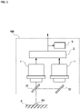
Fig. 1 is an overall schematic of a radiation thermometer according to a first embodiment of the present invention. -
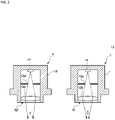
Fig. 2 is a schematic of the internal structure of infrared detectors according to the embodiment. -
Fig. 3 is a visual field diagram of a measurement target region and other region (non-target object) in a measurement visual field according to the embodiment. -
Fig. 4 is an overall schematic of the radiation thermometer according to a modification of the embodiment. -
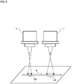
Fig. 5 is an overall schematic of the radiation thermometer according to another modification of the embodiment. -
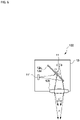
Fig. 6 is an overall schematic of the radiation thermometer according to another modification of the embodiment. -
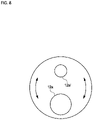
Fig. 7 is a schematic of a mirror and a translucent plate according to the modification. -
Fig. 8 is a schematic of apertures according to still another modification of the embodiment. -
Fig. 9 is an overall schematic of the radiation thermometer according to another modification of the embodiment. -
Fig. 10 is an overall schematic of a radiation thermometer according to a second embodiment of the present invention. -
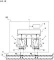
Fig. 11 is a schematic of the internal structure of infrared detectors according to a modification of the embodiment. -
Fig. 12 is an overall schematic of a radiation thermometer according to a third embodiment of the present invention. -
- 100 radiation thermometer
- X object
- Xa measurement target region
- 1, 1' infrared detector
- 2 temperature calculator
- Vf, Vf measurement visual field
- α, α' viewing angle
- Embodiments of the present invention are described with reference to the accompanying drawings.
- A
radiation thermometer 100 according to the present embodiment measures the temperature of a measurement target region Xa in an object X in a non-contact manner as illustrated inFig. 1 . Theradiation thermometer 100 is a non-contact thermometer and includes a pair ofinfrared detectors 1 and 1', atemperature calculator 2, and atemperature display unit 3. The pair ofinfrared detectors 1 and 1' detects infrared rays emitted from the object X. Thetemperature calculator 2 calculates the temperature of the measurement target region Xa based on the amounts of infrared rays detected by the respectiveinfrared detectors 1 and 1'. - Before explaining the configuration of the
radiation thermometer 100 in detail, the structure of the object X is described first. As illustrated inFig. 1 , the object X has a flat plate shape and is provided with a heat transfer block Y attached to a first surface of the object X to control the temperature of the object X. Theradiation thermometer 100 is disposed facing the first surface of the object X and fails to measure the temperature of the object X because the heat transfer block Y obstructs the measurement as it is. To address this, two thin holes Yh having the same diameter are formed in the heat transfer block Y, and theradiation thermometer 100 can measure the temperature of the object X through the thin holes Yh. In other words, the regions exposed through the thin holes Yh in the object X are the measurement target regions Xa. - The object X according to the embodiment does not substantially have a positional temperature gradient. While the thin holes Yh are formed at two positions in the heat transfer block 7, and there are apparently two measurement target regions Xa, these two measurement target regions Xa have substantially the same area, the same shape, and the same temperature. Consequently, these two measurement target regions Xa can be considered as the same measurement target region Xa. Regions surrounding the thin holes Yh in the heat transfer block 7 also have the same temperature, the same shape, and other factors. For this reason, the surrounding conditions of these two measurement target regions Xa can also be considered equal.
- In other words, the present embodiment has two measurement target regions Xa substantially equal in all the factors including the surrounding conditions and can consider that the
radiation thermometer 100 measures a single measurement target region Xa. - The following describes various units of the
radiation thermometer 100. - As illustrated in
Fig. 2 , the pair ofinfrared detectors 1 and 1' includessensor elements 11 and 11',optical systems 12 and 12', andhousings 13 and 13', respectively. Thesensor elements 11 and 11', such as thermopiles, detect infrared rays. Theoptical systems 12 and 12' are disposed in front of thesensor elements 11 and 11', respectively. Thehousings 13 and 13' house thesensor elements 11 and 11' and theoptical systems 12 and 12', respectively. - The
infrared detectors 1 and 1' are disposed side by side facing the respective thin holes Yh. One infrared detector 1 (first infrared detector 1) receives infrared rays emitted from the measurement target region Xa at the bottom of one thin hole Yh, and the other infrared detector 1' (second infrared detector 1') receives infrared rays emitted from the measurement target region Xa at the bottom of the other thin hole Yh. The distances between theinfrared detectors 1 and 1' and the respective measurement target regions Xa are set to be equal. - The
sensor elements 11 and 11' are thermal elements that detect a change in temperature caused when absorbing infrared rays as a change in electromotive force. Thesensor elements 11 and 11' according to the present embodiment are thermopiles in which a number of thermocouples are disposed in series and formed in thin films. The sensor elements may be other thermal elements, such as porometers and pyroelectric elements, or quantum elements instead of thermal elements may be used. - The
optical systems 12 and 12' includelenses apertures sensor elements 11 and 11', respectively. Theoptical systems 12 and 12' define solid angles (viewing angles) α and α' of infrared rays incident on thesensor elements 11 and 11' from the outside and eventually define measurement visual fields Vf and Vf, respectively. The measurement visual fields Vf and Vf of the respectiveinfrared detectors 1 and 1' are each set to include the whole corresponding measurement target region Xa and the surrounding region of the measurement target region Xa. - Consequently, the first
infrared detector 1 and the second infrared detector 1' according to the embodiment have different sizes of the measurement visual fields Vf and Vf with respect to the measurement target region Xa by making only the viewing angles α and α' different. In other words, the firstinfrared detector 1 and the second infrared detector 1' have different ratios of the area occupied by the measurement target region Xa to the measurement visual fields Vf and Vf. In this embodiment, for example, only the lens curvature of theoptical systems 12 and 12' are different and the other configurations are the same. -
Fig. 3 illustrates the size of each of the measurement visual fields Vf and Vf with respect to the measurement target region Xa. A region other than the measurement target region Xa in each of the measurement visual fields Vf and Vf according to the embodiment corresponds to the inner wall of the thin hole Yh as illustrated inFig. 1 . The infrared rays emitted from the inner wall of the thin hole Yh is incident on each of theinfrared detectors 1 and 1'. - The
temperature calculator 2 includes electric circuits (not illustrated), such as a buffer, an amplifier, an AD converter, a CPU, a memory, and other components. The CPU cooperates with peripheral devices according to a computer program stored in the memory, thereby implementing a function of calculating the temperature of the temperature measurement target region Xa based on the values of detection signals output from thesensor elements 11 and 11'. The temperature calculated by thetemperature calculator 2 is output as temperature signals. - The
temperature display unit 3 includes a display and other components and receives the temperature signals to display the temperature on the display. - The
temperature calculator 2 and the temperature display unit 4 are not necessarily provided near theinfrared detectors 1 and 1' and may be disposed at any desired positions as long as they are wired or wirelessly connected. - In addition, a temperature control device (not illustrated) that receives the temperature signals and controls the temperature of the object may be prepared and the
radiation thermometer 100 and the temperature control device may constitute a temperature measurement control system. - The following specifically describes an example of a method of calculating the temperature of the measurement target region Xa by the
temperature calculator 2. - The value of the detection signals output from the
sensor elements 11 and 11' (hereinafter referred to as the amount of detected infrared rays) is the sum of the value obtained by multiplying the temperature of the measurement target region Xa by the ratio of the area occupied by the measurement target region Xa to the measurement visual fields Vf and Vf and the value obtained by multiplying the temperature of the surrounding region (heat transfer block Y) by the ratio of the area occupied by the surrounding region to the measurement visual fields Vf and Vf, respectively. - The measurement visual field is one of visual field characteristics (consisting of various indicators indicating what kind of visual field the radiation thermometer has) and indicates the size of a target size set as a measurement target at a certain measurement distance by the radiation thermometer. Typically, the measurement visual field is determined to be a diameter equivalent to 90% of the total incident energy.
- Spectral radiant energy of a black body with a temperature T at a wavelength λ is defined as E(λ,T). When the temperature of the measurement target region Xa is T1, the temperature of the surrounding region is T2, the spectral radiant energy from the measurement target region Xa to the sensor element 11 of the first infrared detector 1 having a sensitivity of wavelength λ1 is E(λ1,T1) = E1(T1), the spectral radiant energy from the surrounding region is E(λ1,T2) = E1(T2), the ratio of the amount of incident light (area ratio) occupied by the measurement target region Xa to the measurement visual field Vf of the infrared detector 1 is R1, the spectral radiant energy from the measurement target region Xa to the sensor element 11' of the second infrared detector 1' having a sensitivity at wavelength λ2 is E(λ2,T1) = E2(T1), the spectral radiant energy from the surrounding region is E(λ2,T2) = E2(T2), the ratio of the amount of incident light (area ratio) occupied by the measurement target region Xa to the measurement visual field Vf of the infrared detector 1' is R2, the spectral radiant energy incident on the sensor element 11 of the first infrared detector 1 is W1, and the spectral radiant energy incident on the sensor element 11' of the second infrared detector 1' is W2, the following expressions are satisfied if emissivity and other coefficients are omitted:


- If λ1 = λ2, that is, if E1(T1) = E2(T1) and E1(T2) = E2(T2) are satisfied, T1 is expressed by:

- If λ1 ≠ λ2, that is, if E1(T1) ≠ E2(T1) and E1(T2) ≠ E2(T2) are satisfied,


- T1 satisfying Expression (4) is solved by the bisection method or the like.
- The
temperature calculator 2 stores Expressions (3) and (4) and the known values R1 and R2 in the memory. Thetemperature calculator 2 calculates the temperature T1 of the measurement target region Xa by substituting the values W1 and W2 of the detection signals obtained by theinfrared detectors 1 and 1' and the values R1 and R2 into Expressions (3) and (4). - With this configuration, as is clear from the fact that T2 is not present in Expression (3) or (4), the temperature of the measurement target region Xa can be measured independently of the temperature of regions other than the measurement target region Xa. Consequently, the present embodiment can accurately measure the temperature without being affected by a temporal change in temperature of the other regions and a positional temperature gradient at all.
- The first embodiment may have various modifications.
- The embodiment described above, for example, makes the viewing angles α and α' of the
infrared detectors 1 and 1' different to vary the ratio of the area occupied by the temperature measurement target region Xa to the measurement visual fields Vf and Vf between theinfrared detectors 1 and 1'. The embodiment, however, may vary the distance between the temperature measurement target region Xa and theinfrared detectors 1 and 1' at the same viewing angle α as illustrated inFig. 4 . - The
infrared detectors 1 and 1' may differ from each other in the viewing angle and the distance. - The embodiment described above has the two identical measurement target regions Xa having the same surrounding conditions so as to correspond to the two
infrared detectors 1 and 1' having different visual field characteristics. If there is one measurement target region Xa as illustrated inFig. 5 , for example, abeam splitter 31 may be prepared to divide the infrared rays into two parts and introduce them into the respectiveinfrared detectors 1 and 1'. The viewing angles of theinfrared detectors 1 and 1' are the same in this case, but the distances (optical path lengths) between the temperature measurement target region Xa and theinfrared detectors 1 and 1' are different as described above.Reference sign 32 denotes a mirror. - More specifically, the present invention can also be embodied with a single infrared detector. For example, a zoom mechanism capable of adjusting the position of the lens of the optical system may be prepared to perform measurement twice at predetermined time intervals and vary the magnification/reduction rate of the zoom mechanism (ratio of the area occupied by the temperature measurement target region to the measurement visual field in each measurement) for each measurement.
- More specifically, in the first measurement, a first measurement visual field including the measurement target region is set by adjusting the zoom mechanism and the amount of infrared rays incident from the first measurement visual field is detected. In the second measurement, a second measurement visual field including the measurement target region and having a size different from that of the first measurement visual field with respect to the measurement target region is set by adjusting the zoom mechanism and the amount of infrared rays incident from the second measurement visual field is detected.
- After obtaining the amounts of infrared rays from the two different measurement fields in this manner, the temperature of the measurement target region may be calculated by the same method as that described in the embodiment above.
- This method can be carried out not only by using the optical system, but for example also by changing a distance between the infrared detector and the temperature measurement target region with a distance adjustment mechanism prepared to adjust the distance.
- The
radiation thermometer 100 may be the one illustrated inFig. 6 . Thisradiation thermometer 100 includes twosensor elements 11 and 11' (corresponding to infrared detectors in the claims) in a single housing. Thelens 12b is shared by thesensor elements 11 and 11', and one of amirror 12c and atranslucent plate 12d can be selectively disposed on the optical path of the infrared rays incident from thelens 12b. More specifically, themirror 12c and thetranslucent plate 12d are alternately formed on a single disc in this example as illustrated inFig. 7 . By rotating the disc, one of themirror 12c and thetranslucent plate 12d is disposed on the optical path. - When the translucent plate is selected, one
sensor element 11 is enabled, that is, the infrared rays emitted from the measurement target region are incident on thesensor element 11. When the mirror is selected, the other sensor element 11' is enabled, that is, the infrared rays emitted from the measurement target region are incident on the sensor element 11'. - Consequently, by making the optical path lengths from the
lens 12b to therespective sensor elements sensor element 11 and the size of the measurement visual field of the sensor element 11' (to be precise, the ratio of the area occupied by the temperature measurement target region to the measurement visual field)' are different. - The measurement procedure in this example needs to be performed twice similarly to the example using the zoom mechanism. This procedure includes the first measurement with the
mirror 12c and the second measurement with thetranslucent plate 12d. - The measurement visual field can also vary by changing the diameter of the aperture in the optical system. If two infrared detectors are provided, the measurement visual fields can vary by changing the diameters of the apertures without changing the lens powers or the optical path lengths. If a single infrared detector is provided, two apertures having different diameters may be prepared in a movable manner such that one of the apertures can be used. In
Fig. 8 , for example, two apertures having different diameters are provided to a disc, and one of the apertures can be selectively used by rotating the disc. The aperture diameter may be changed not only by rotating the disc, but also by selecting the aperture through sliding movement or using an aperture variable mechanism. - The temperature calculation routine by the temperature calculator is not only used as described in the embodiment above, but may also be used to, for example, calculate the temperature of the measurement target region using simultaneous equations or calculate the temperature of the measurement target region based on a temperature map created in advance by an experiment.
- Three or more infrared detectors each having a different size of the measurement visual field may be provided.
- As illustrated in
Fig. 9 , the object X may be a linear object, such as a wire. In this illustrated example, the object X has an equal temperature at any part, including the surrounding region. For this reason, theradiation thermometer 100 according to this example also includes the pair ofinfrared detectors 1 and 1' and measures the two parts of the object X, considering that the parts have the same temperature, similarly to the embodiment above. This example also makes the measurement visual fields Vf and Vf of the respectiveinfrared detectors 1 and 1' different to vary the ratio of the area occupied by the object X (measurement target region) to the measurement visual fields Vf and Vf. - Also this configuration can accurately measure the temperature of the object X if the ratio of the area occupied by the measurement target object (measurement target region) to the measurement visual fields Vf and Vfare known.
- A second embodiment of the present invention is described below.
- As illustrated in
Fig. 10 , theradiation thermometer 100 according to the present embodiment measures the temperature of the measurement target region Xa in the object X in a non-contact manner. Theradiation thermometer 100 includes the pair ofinfrared detectors 1 and 1', thetemperature calculator 2, and thetemperature display unit 3. The pair ofinfrared detectors 1 and 1' detects infrared rays emitted from the object X. Thetemperature calculator 2 calculates the temperature of the measurement target region Xa based on the amount of detected infrared rays that is the amounts of infrared rays detected by the respectiveinfrared detectors 1 and 1'. - As illustrated in
Fig. 10 , the object X has low emissivity (high transmittance) in the wavelength band of infrared rays detectable by theinfrared detectors 1 and 1' (hereinafter referred to as a detectable infrared wavelength band), and there can be infrared rays that are emitted from a body Z in the background, passing through the object X, and incident on the infrared sensors. - The following describes the
radiation thermometer 100. - Similarly to the first embodiment, the pair of
infrared detectors 1 and 1' includes thesensor elements 11 and 11', theoptical systems 12 and 12', and thehousings 13 and 13', respectively, as illustrated inFig. 10 . Thesensor elements 11 and 11', such as thermopiles, detect infrared rays. Theoptical systems 12 and 12' are disposed in front of thesensor elements 11 and 11', respectively. Thehousings 13 and 13' house thesensor elements 11 and 11' and theoptical systems 12 and 12', respectively. - Consequently, the
infrared detectors 1 and 1' have thesame sensor elements 11 and 11', the sameoptical systems 12 and 12', and thesame housings 13 and 13', respectively, and their viewing angles are equal. The distances between the temperature measurement target region Xa and the respectiveinfrared detectors 1 and 1' are also set to be equal. - The
infrared detectors 1 and 1' according to the second embodiment further includeoptical filters 14 and 14', respectively, in front of or behind the optical systems. The optical filters 14 and 14' have transmittable infrared wavelength bands different from each other. As a result, the wavelength bands of infrared rays detectable by theinfrared detectors 1 and 1' (a first detectable infrared wavelength band and a second detectable infrared wavelength band) are made different from each other. The term "being different from each other" herein includes the case where the wavelength bands partially overlap. In other words, the wavelength bands simply need to be not identical perfectly. - The measurement target regions Xa of the
infrared detectors 1 and 1' are identical (while they are different parts of the object X inFig. 10 , they are considered to be identical). - The
temperature calculator 2 calculates the temperature of the measurement target region Xa based on the values of detection signals output from theinfrared detectors 1 and 1' (a first amount of detected infrared rays and a second amount of detected infrared rays). - The principle of the calculation is as follows.
- The total amount of infrared rays in a certain wavelength band incident on the
infrared detectors 1 and 1' is the sum of infrared rays A1 from the measurement target region Xa, infrared rays A2 from behind the measurement target region Xa, and infrared rays A3 reflected by the measurement target region Xa. If the radiation thermometer and the measurement target region directly face each other, A3 is known because it is infrared rays emitted from theradiation thermometer 100. Consequently, the ratio of A1 to A2, that is, R = A1/A2 corresponds to emissivity/transmittance of the measurement target region Xa. - The ratio R is known.
- The
temperature calculator 2 calculates the object temperature from data in two different wavelength bands, that is, the first amount of detected infrared rays and the second amount of detected infrared rays and from the known ratios R1 and R2 in the wavelength bands described above by simultaneous equations, the bisection method, and the like. - The following describes a specific example of calculation.
- When the spectral radiation energy from the measurement target region Xa to the
infrared detector 1 is E1(Tx), the spectral radiation energy from the background of the measurement target region Xa to theinfrared detector 1 is E1(Tbackground), the spectral radiation energy from the measurement target region Xa to the infrared detector 1' is E2(Tx), and the spectral radiation energy from the background of the measurement target region Xa to the second infrared detector 1' is E2(Tbackground),
the spectral radiation energy (first amount of detected infrared rays) W1 detected by the firstinfrared detector 1 is expressed by:

- There are two unknown parameters Tx and Tbackground. Consequently, the following expression is derived using Expressions (5) and (6):

- There is a single solution satisfying Expression (7) because the relation E(T) between spectral radiation energy and temperature monotonically increases. Consequently, the object temperature Tx can be calculated.
- The second embodiment having the configuration described above can reliably eliminate effects of a non-target object that emits infrared rays passing through the measurement visual field if the non-target object is present in the background of the measurement target region Xa and the temperature of the non-target object changes.
- It should be noted that
Japanese Patent Application Laid-open No. H10-38696 - The second embodiment may also have various modifications.
- For example, the bisection method as described in the first embodiment may be used to calculate the temperature. Alternatively, the temperature of the measurement target region may be calculated based on a correlation expression created in advance by an experiment.
- The present invention can also be embodied with a single
infrared detector 1. As illustrated inFig. 11 , for example, a movement mechanism is provided to selectively move, onto the optical path, one of theoptical filters 14 and 14' having transmittable infrared wavelength bands different from each other, the firstoptical filter 14 is used in the first measurement, and the second optical filter 14' is used in the second measurement performed after a predetermined time has elapsed since the first measurement. After obtaining the amounts of infrared rays in the two measurements, the temperature of the measurement target region may be calculated by the same method as that described in the embodiment above. While a rotary disc is used in the movement mechanism in this example, a sliding mechanism or other mechanisms may be used. - The number of optical filters is not limited to two and may be three or more. Similarly, three or more infrared detectors having different detectable infrared wavelength bands may be used.
- A third embodiment of the present invention is described below.
- As illustrated in
Fig. 12 , theradiation thermometer 100 according to the present embodiment measures the temperature of the measurement target region Xa in the object X in a non-contact manner. Theradiation thermometer 100 includes the pair ofinfrared detectors 1 and 1', thetemperature calculator 2, and thetemperature display unit 3. The pair ofinfrared detectors 1 and 1' detects infrared rays emitted from the object X. Thetemperature calculator 2 calculates the temperature of the measurement target region Xa based on the amount of detected infrared rays that is the amounts of infrared rays detected by the respectiveinfrared detectors 1 and 1'. The object X has a transmittance of 0. - The following describes the
radiation thermometer 100. - Similarly to the first embodiment, the pair of
infrared detectors 1 and 1' includes thesensor elements 11 and 11', theoptical systems 12 and 12', and thehousings 13 and 13', respectively, as illustrated inFig. 12 . Thesensor elements 11 and 11', such as thermopiles, detect infrared rays. Theoptical systems 12 and 12' are disposed in front of thesensor elements 11 and 11', respectively. Thehousings 13 and 13' house thesensor elements 11 and 11' and theoptical systems 12 and 12', respectively. Theinfrared detectors 1 and 1' have measurement optical axes β, which are the optical axes of the respectiveoptical systems 12 and 12', respectively. The measurement visual field has the size of the target size set as the measurement target by the radiation thermometer and defined based on the measurement optical axis β. - Consequently, the
infrared detectors 1 and 1' have thesame sensor elements 11 and 11', the sameoptical systems 12 and 12', and thesame housings 13 and 13', respectively, and their viewing angles are equal. The optical path lengths on the measurement optical axes β between the temperature measurement target region Xa and the respectiveinfrared detectors 1 and 1' are also set to be equal. In addition, the points of intersection of the measurement optical axes β of the respectiveinfrared detectors 1 and 1' with the surface of the measurement target region Xa are also identical. By contrast, the angles of the measurement optical axes β of the respectiveinfrared detectors 1 and 1' to an object surface Xs are set to be different from each other. - The
temperature calculator 2 calculates the temperature of the measurement target region Xa based on the values of detection signals output from theinfrared detectors 1 and 1' (the first amount of detected infrared rays and the second amount of detected infrared rays) and on the reflectance or the emissivity at each of the angles. - The principle of the calculation is as follows.
- When an angle θ of the measurement optical axis β to the object surface Xs changes, reflectance R and emissivity ε also change. For this reason, spectral radiation energies W incident on the
infrared detectors 1 and 1' are different from each other. - The
temperature calculator 2 calculates the object temperature from data at different angles, that is, the first amount of detected infrared rays and the second amount of detected infrared rays and from one or both of known reflectances R(θ1) and R(θ2) and known emissivities ε(θ1) and ε(θ2) at the angles θ1 and θ2 by simultaneous equations, the bisection method, and the like. - The following describes a specific example of calculation.
- When the spectral radiation energy from the measurement target region Xa to the
infrared detector 1 is E1(Tx), the spectral radiation energy that is emitted from the surrounding region, reflected by the surface of the measurement target region Xa, and incident on theinfrared detector 1 is E1(TR), the spectral radiation energy from the measurement target region Xa to the infrared detector 1' is E2(Tx), and the spectral radiation energy that is emitted from the surrounding region, reflected by the surface of the measurement target region Xa, and incident on the second infrared detector 1' is E2(TR), - the spectral radiation energy (first amount of detected infrared rays) W1 detected by the first
infrared detector 1 is expressed by:
- the spectral radiation energy (second amount of detected infrared rays) W2 detected by the second infrared detector 1' is expressed by:

- If E1(Tx) = E2(Tx) = E(Tx) and E1(TR) = E2(TR) = E(TR) are satisfied, there are two unknown parameters E(Tx) and E(TR). Consequently, the following expression is derived using Expressions (8) and (9):

- If E1(Tx) ≠ E2(TX) and E1(TR) ≠ E2(TR) are satisfied, the object temperature fails to be calculated by simultaneous equations. It is necessary to use the bisection method or the like.
- With the third embodiment having the configuration described above, as is clear from the fact that TR is not present in Expression (10), the temperature of the measurement target region Xa can be measured independently of the temperature of regions other than the measurement target region Xa. Consequently, the third embodiment can accurately measure the temperature without being affected by a temporal change in temperature of the other regions and a positional temperature gradient at all.
- The third embodiment may also have various modifications.
- For example, the bisection method as described in the first embodiment may be used to calculate the temperature. Alternatively, the temperature of the measurement target region may be calculated based on a correlation expression created in advance by an experiment.
- The present invention can also be embodied with a single
infrared detector 1. For example, an angle adjusting mechanism is prepared to mechanically move theinfrared detector 1 to adjust the angle of the measurement optical axis β to the object surface Xs, the first measurement is performed at a certain angle, and the second measurement is performed at an angle different from the certain angle. After obtaining the amounts of infrared rays in the two measurements, the temperature of the measurement target region may be calculated by the same method as that described in the embodiment above. In addition, the points of intersection of the measurement optical axes β with the surface of the object Xs need not be exactly identical. The points of intersection of the measurement optical axes β with the object Xs simply need to be set such that the measurement target region Xa is included in the measurement visual field at each angle θ, for example. - While the sensor elements, the optical systems, the housings, the viewing angles, and other components constituting the infrared detectors are the same in the third embodiment, they may differ between the detectors. In addition, the optical path lengths of infrared rays detected by the infrared detectors are not necessarily the same. In other words, the respective infrared detectors simply need to detect infrared rays, in a state in which reflectances of infrared rays reflected by the measurement target region of the respective infrared detectors are different. If the reflectance of infrared rays in the measurement target region differs depending on the wavelength of the infrared rays, for example, the infrared detectors simply need to be able to detect different wavelengths. With this configuration, the temperature can be accurately calculated by the temperature calculation method described in the third embodiment even if the angles between the measurement optical axes of the respective infrared detectors and the measurement target region are the same.
- Three or more infrared detectors each having a different angle may be provided.
- Part or the whole of the configuration according to the first to the third embodiments can be combined.
- Part of the configurations according to the embodiments and the modifications described above may be appropriately combined or transformed without departing from the spirit of the present invention.
- The present invention can provide a radiation thermometer that can accurately measure the temperature of the measurement target region in a non-contact manner regardless of how the temperature of regions other than the measurement target region changes.
Claims (16)
- A radiation thermometer configured to measure a temperature of a measurement target region in an object, the radiation thermometer comprising:two infrared detectors each having a predetermined measurement visual field and configured to detect an amount of infrared rays incident from the measurement visual field; anda temperature calculator configured to calculate the temperature of the measurement target region based on the amounts of infrared rays detected by the respective infrared detectors, whereinthe measurement target region is included in the measurement visual fields of the respective infrared detectors, and the sizes of the respective measurement visual fields are set to be different from each other with respect to the measurement target region.
- The radiation thermometer according to claim 1, wherein the temperature calculator calculates the temperature of the measurement target region based on a ratio of the size of the measurement target region to the measurement visual field of each of the respective infrared detectors besides the amount of infrared rays detected by the respective infrared detectors.
- The radiation thermometer according to claim 1 or 2, whereinthe infrared detectors each comprise an infrared sensor configured to detect an amount of incident infrared rays and an optical system disposed in front of the infrared sensor and configured to define a viewing angle that is a solid angle of the infrared rays incident on the infrared sensor, anddistances between the respective infrared detectors and the measurement target region are set to be equal to each other, and the viewing angles of the respective infrared detectors are set to be different from each other.
- The radiation thermometer according to claim 1 or 2, whereinthe infrared detectors each comprise an infrared sensor configured to detect an amount of incident infrared rays and an optical system disposed in front of the infrared sensor and configured to define a viewing angle that is a solid angle of the infrared rays incident on the infrared sensor, andthe viewing angles of the respective infrared detectors are set to be equal to each other, and distances between the respective infrared detectors and the measurement target region are set to be different from each other.
- A temperature measurement method for measuring a temperature of a measurement target region in an object, the temperature measurement method comprising:setting a first measurement visual field including the measurement target region and detecting an amount of infrared rays incident from the first measurement visual field;setting a second measurement visual field including the measurement target region and having a size different from the size of the first measurement visual field with respect to the measurement target region, and detecting an amount of infrared rays incident from the second measurement visual field; andcalculating the temperature of the measurement target region based on the amounts of infrared rays.
- A temperature measurement program used to measure a temperature of a measurement target region in an object, the temperature measurement program causing a computer to implement a function as
a temperature calculator configured to calculate the temperature of the measurement target region based on an amount of infrared rays detected in a first measurement visual field including the measurement target region and on an amount of infrared rays detected in a second measurement visual field including the measurement target region and having a size different from the size of the first measurement visual field with respect to the measurement target region. - A radiation thermometer configured to measure a temperature of a measurement target region in an object, the radiation thermometer comprising:two infrared detectors each having a predetermined measurement visual field and configured to detect an amount of infrared rays incident from the measurement visual field; anda temperature calculator configured to calculate the temperature of the measurement target region based on the amounts of infrared rays detected by the respective infrared detectors, whereindetectable infrared wavelength bands detectable by the respective infrared detectors are different from each other.
- The radiation thermometer according to claim 7, wherein the temperature calculator calculates the temperature of the measurement target region based further on a ratio between emissivity and transmittance of infrared rays in the measurement target region.
- A temperature measurement method for measuring a temperature of a measurement target region in an object, the temperature measurement method comprising:setting a predetermined measurement visual field including the measurement target region;detecting an amount of infrared rays incident from the measurement visual field in a predetermined first detectable infrared wavelength band and detecting the amount of infrared rays in a second detectable infrared wavelength band different from the first detectable infrared wavelength band; andcalculating the temperature of the measurement target region based on the detected amounts of infrared rays.
- A temperature measurement program used to measure a temperature of a measurement target region in an object, the temperature measurement program causing a computer to implement a function as
a temperature calculator configured to calculate the temperature of the measurement target region based on a first amount of detected infrared rays obtained by detecting an amount of infrared rays incident from a predetermined measurement visual field including the measurement target region in a predetermined first detectable infrared wavelength band and on a second detected amount of infrared rays obtained by detecting the amount of infrared rays in a second detectable infrared wavelength band different from the first detectable infrared wavelength band. - A radiation thermometer configured to measure a temperature of a measurement target region in an object, the radiation thermometer comprising:two infrared detectors each having a predetermined measurement visual field and configured to detect an amount of infrared rays incident from the measurement visual field; anda temperature calculator configured to calculate the temperature of the measurement target region based on the amounts of infrared rays detected by the respective infrared detectors, whereinthe measurement target region is included in the measurement visual fields of the respective infrared detectors, and reflectances of infrared rays in the measurement target region of the respective infrared detectors are set to be different from each other.
- The radiation thermometer according to claim 11, wherein the infrared detectors each have a predetermined measurement optical axis, and angles of the measurement optical axes to a surface of the object are different from each other.
- The radiation thermometer according to claim 12, wherein the temperature calculator calculates the temperature of the measurement target region based further on one or both of emissivity and reflectance of infrared rays in the measurement target region.
- A temperature measurement method for measuring a temperature of a measurement target region in an object, the temperature measurement method comprising:setting a predetermined measurement visual field including the measurement target region;causing infrared rays to be reflected by the measurement target region with first reflectance and detecting an amount of infrared rays incident from the measurement visual field;causing infrared rays to be reflected by the measurement target region with second reflectance different from the first reflectance and detecting an amount of infrared rays incident from the measurement visual field; andcalculating the temperature of the measurement target region based on the detected amounts of infrared rays.
- The temperature measurement method according to claim 14, whereina measurement optical axis is set to have a first angle to a surface of the object to cause the infrared rays to be reflected by the measurement target region with the first reflectance, anda measurement optical axis is set to have a second angle different from the first angle to the surface of the object to cause the infrared rays to be reflected by the measurement target region with the second reflectance.
- A temperature measurement program used to measure a temperature of a measurement target region in an object, the temperature measurement program causing a computer to implement a function as
a temperature calculator configured to calculate the temperature of the measurement target region based on an amount of infrared rays detected in a state in which the infrared rays are caused to be reflected by the measurement target region with first reflectance and on an amount of infrared rays detected in a state in which the infrared rays are caused to be reflected by the measurement target region with second reflectance different from the first reflectance.
Priority Applications (1)
| Application Number | Priority Date | Filing Date | Title |
|---|---|---|---|
| EP26151326.1A EP4707759A1 (en) | 2019-10-25 | 2020-10-23 | Radiation thermometer, temperature measurement method, and temperature measurement program |
Applications Claiming Priority (3)
| Application Number | Priority Date | Filing Date | Title |
|---|---|---|---|
| JP2019194134 | 2019-10-25 | ||
| JP2020071243 | 2020-04-10 | ||
| PCT/JP2020/039962 WO2021080002A1 (en) | 2019-10-25 | 2020-10-23 | Radiation thermometer, temperature measurement method, and temperature measurement program |
Related Child Applications (1)
| Application Number | Title | Priority Date | Filing Date |
|---|---|---|---|
| EP26151326.1A Division EP4707759A1 (en) | 2019-10-25 | 2020-10-23 | Radiation thermometer, temperature measurement method, and temperature measurement program |
Publications (3)
| Publication Number | Publication Date |
|---|---|
| EP4040122A1 true EP4040122A1 (en) | 2022-08-10 |
| EP4040122A4 EP4040122A4 (en) | 2023-11-22 |
| EP4040122B1 EP4040122B1 (en) | 2026-02-18 |
Family
ID=75620149
Family Applications (2)
| Application Number | Title | Priority Date | Filing Date |
|---|---|---|---|
| EP26151326.1A Pending EP4707759A1 (en) | 2019-10-25 | 2020-10-23 | Radiation thermometer, temperature measurement method, and temperature measurement program |
| EP20878512.1A Active EP4040122B1 (en) | 2019-10-25 | 2020-10-23 | Radiation thermometer, temperature measurement method, and temperature measurement program |
Family Applications Before (1)
| Application Number | Title | Priority Date | Filing Date |
|---|---|---|---|
| EP26151326.1A Pending EP4707759A1 (en) | 2019-10-25 | 2020-10-23 | Radiation thermometer, temperature measurement method, and temperature measurement program |
Country Status (4)
| Country | Link |
|---|---|
| US (1) | US12523532B2 (en) |
| EP (2) | EP4707759A1 (en) |
| JP (2) | JP7785539B2 (en) |
| WO (1) | WO2021080002A1 (en) |
Families Citing this family (2)
| Publication number | Priority date | Publication date | Assignee | Title |
|---|---|---|---|---|
| CN115711730A (en) * | 2022-11-29 | 2023-02-24 | 北京航天长征飞行器研究所 | Infrared target simulation system with continuously controllable motion, energy and scale |
| JPWO2024241674A1 (en) | 2023-05-25 | 2024-11-28 |
Family Cites Families (19)
| Publication number | Priority date | Publication date | Assignee | Title |
|---|---|---|---|---|
| JPS61231422A (en) * | 1985-04-06 | 1986-10-15 | Horiba Ltd | Radiation thermometer |
| JPS62106328A (en) | 1985-11-01 | 1987-05-16 | Tokyo Electric Power Co Inc:The | Radiation thermometer |
| JPS6375629A (en) | 1986-09-19 | 1988-04-06 | Minolta Camera Co Ltd | Radiation thermometer |
| JPS63285429A (en) | 1987-05-18 | 1988-11-22 | Teijin Ltd | Running yarn thermometer |
| JPH0756471B2 (en) * | 1988-09-27 | 1995-06-14 | 登 中谷 | Simultaneous measurement of particle velocity, diameter and refractive index by laser multifocal method |
| US5249142A (en) * | 1989-03-31 | 1993-09-28 | Tokyo Electron Kyushu Limited | Indirect temperature-measurement of films formed on semiconductor wafers |
| JP2832456B2 (en) | 1989-06-02 | 1998-12-09 | 株式会社加藤製作所 | Outriggers for special vehicles |
| JPH08320258A (en) * | 1995-05-25 | 1996-12-03 | Matsushita Electric Ind Co Ltd | Object detection method and apparatus using thermal image information and position information |
| JPH1038696A (en) | 1996-07-18 | 1998-02-13 | Sony Corp | Infrared detector |
| JP2001249050A (en) | 2000-03-07 | 2001-09-14 | Toshiba Corp | Temperature measuring device, film forming device, etching device, temperature measuring method, etching method |
| JP2002188962A (en) | 2000-12-19 | 2002-07-05 | Tokyo Electron Ltd | Radiation temperature measuring device, radiation temperature measuring method, and semiconductor manufacturing device |
| JP2005207997A (en) | 2004-01-26 | 2005-08-04 | Dainippon Screen Mfg Co Ltd | Substrate processing apparatus |
| JP2007183207A (en) | 2006-01-10 | 2007-07-19 | Yamatake Corp | Radiation temperature sensor and radiation temperature measuring device |
| US8254767B2 (en) | 2008-08-29 | 2012-08-28 | Applied Materials, Inc. | Method and apparatus for extended temperature pyrometry |
| KR101500965B1 (en) * | 2011-07-06 | 2015-03-17 | 가부시키가이샤 무라타 세이사쿠쇼 | Method for determining laminate direction for laminate type electronic component, laminate direction determination device for laminate type electronic component, method for manufacturing serial laminate type electronic component, and manufacturing device for serial laminate type electronic component |
| JP2013200137A (en) | 2012-03-23 | 2013-10-03 | Omron Corp | Infrared temperature measurement device, infrared temperature measurement method, and infrared temperature measurement device control program |
| JP6198411B2 (en) | 2013-03-04 | 2017-09-20 | 大阪瓦斯株式会社 | Temperature measuring device |
| KR20170099157A (en) * | 2016-02-23 | 2017-08-31 | 삼성전자주식회사 | Providing temperature information and electronic device supporting the same |
| EP4303547A4 (en) * | 2021-04-09 | 2025-04-09 | HORIBA, Ltd. | Radiation temperature measuring device and method |
-
2020
- 2020-10-23 EP EP26151326.1A patent/EP4707759A1/en active Pending
- 2020-10-23 WO PCT/JP2020/039962 patent/WO2021080002A1/en not_active Ceased
- 2020-10-23 US US17/770,736 patent/US12523532B2/en active Active
- 2020-10-23 JP JP2021553573A patent/JP7785539B2/en active Active
- 2020-10-23 EP EP20878512.1A patent/EP4040122B1/en active Active
-
2025
- 2025-12-03 JP JP2025226291A patent/JP2026026307A/en active Pending
Also Published As
| Publication number | Publication date |
|---|---|
| JPWO2021080002A1 (en) | 2021-04-29 |
| US20220364930A1 (en) | 2022-11-17 |
| JP7785539B2 (en) | 2025-12-15 |
| EP4040122A4 (en) | 2023-11-22 |
| JP2026026307A (en) | 2026-02-16 |
| EP4040122B1 (en) | 2026-02-18 |
| EP4707759A1 (en) | 2026-03-11 |
| US12523532B2 (en) | 2026-01-13 |
| WO2021080002A1 (en) | 2021-04-29 |
Similar Documents
| Publication | Publication Date | Title |
|---|---|---|
| US7422365B2 (en) | Thermal imaging system and method | |
| JP2026026307A (en) | Radiation thermometer, temperature measurement method and temperature measurement program | |
| US8830473B2 (en) | Device for referenced measurements of reflected light and a method for calibrating such a device | |
| US20140129179A1 (en) | System and apparatus for multi channel gloss measurements | |
| US10704963B2 (en) | Infrared contrasting color emissivity measurement system | |
| Watanabe et al. | Spectral emissivity measurements | |
| Yoo et al. | Spectral responsivity calibration of the reference radiation thermometer at KRISS by using a super-continuum laser-based high-accuracy monochromatic source | |
| CN106053023A (en) | Analysis method for stray radiation of infrared measurement system | |
| US4035654A (en) | Optical alignment sensor | |
| US4605314A (en) | Spectral discrimination pyrometer | |
| US5084621A (en) | Radiometric standard infrared detector | |
| US20170307445A1 (en) | Medical thermometer having an improved optics system | |
| Montgomery et al. | The algorithm for MODIS wavelength on-orbit calibration using the SRCA | |
| US10876898B2 (en) | Passive millimeter wave radiometer system for calibration of infrared cameras | |
| EP4692742A1 (en) | Radiation temperature measurement device, radiation temperature measurement method, and program for radiation temperature measurement device | |
| Cabib et al. | High performance spectroradiometer for very accurate radiometric calibrations and testing of blackbody sources and EO test equipment | |
| Zhang et al. | Design and calibration of electrical substitution radiometer traced to absolute cryogenic radiometer | |
| JPH06147995A (en) | Infrared detecting device | |
| CN111562019B (en) | A kind of multispectral radiation temperature measurement method and system | |
| JP3325700B2 (en) | Optical fiber radiation thermometer | |
| Natsume et al. | Method to identify optical path transmittance by using cat’s-eye retroreflectors | |
| Aleshko et al. | Influence of the Narcissus effect on the results of the calibration of test stands for measuring the parameters of optoelectronic devices | |
| IL110549A (en) | Multipoint temperature monitoring apparatus for semiconductor wafers during processing | |
| Poulsen et al. | New method of high-precision thermometry | |
| JPS62261933A (en) | Radiation thermometer and its using method |
Legal Events
| Date | Code | Title | Description |
|---|---|---|---|
| STAA | Information on the status of an ep patent application or granted ep patent |
Free format text: STATUS: THE INTERNATIONAL PUBLICATION HAS BEEN MADE |
|
| PUAI | Public reference made under article 153(3) epc to a published international application that has entered the european phase |
Free format text: ORIGINAL CODE: 0009012 |
|
| STAA | Information on the status of an ep patent application or granted ep patent |
Free format text: STATUS: REQUEST FOR EXAMINATION WAS MADE |
|
| 17P | Request for examination filed |
Effective date: 20220502 |
|
| AK | Designated contracting states |
Kind code of ref document: A1 Designated state(s): AL AT BE BG CH CY CZ DE DK EE ES FI FR GB GR HR HU IE IS IT LI LT LU LV MC MK MT NL NO PL PT RO RS SE SI SK SM TR |
|
| DAV | Request for validation of the european patent (deleted) | ||
| DAX | Request for extension of the european patent (deleted) | ||
| RIC1 | Information provided on ipc code assigned before grant |
Ipc: G01J 5/0831 20220101ALI20230823BHEP Ipc: G01J 5/0802 20220101ALI20230823BHEP Ipc: G01J 5/80 20220101ALI20230823BHEP Ipc: G01J 5/08 20220101ALI20230823BHEP Ipc: G01J 5/07 20220101ALI20230823BHEP Ipc: G01J 5/02 20220101AFI20230823BHEP |
|
| A4 | Supplementary search report drawn up and despatched |
Effective date: 20231025 |
|
| RIC1 | Information provided on ipc code assigned before grant |
Ipc: G01J 5/0831 20220101ALI20231019BHEP Ipc: G01J 5/0802 20220101ALI20231019BHEP Ipc: G01J 5/80 20220101ALI20231019BHEP Ipc: G01J 5/08 20220101ALI20231019BHEP Ipc: G01J 5/07 20220101ALI20231019BHEP Ipc: G01J 5/02 20220101AFI20231019BHEP |
|
| P01 | Opt-out of the competence of the unified patent court (upc) registered |
Effective date: 20231108 |
|
| STAA | Information on the status of an ep patent application or granted ep patent |
Free format text: STATUS: EXAMINATION IS IN PROGRESS |
|
| 17Q | First examination report despatched |
Effective date: 20241220 |
|
| GRAP | Despatch of communication of intention to grant a patent |
Free format text: ORIGINAL CODE: EPIDOSNIGR1 |
|
| STAA | Information on the status of an ep patent application or granted ep patent |
Free format text: STATUS: GRANT OF PATENT IS INTENDED |
|
| INTG | Intention to grant announced |
Effective date: 20250919 |
|
| GRAS | Grant fee paid |
Free format text: ORIGINAL CODE: EPIDOSNIGR3 |
|
| GRAA | (expected) grant |
Free format text: ORIGINAL CODE: 0009210 |
|
| STAA | Information on the status of an ep patent application or granted ep patent |
Free format text: STATUS: THE PATENT HAS BEEN GRANTED |
|
| AK | Designated contracting states |
Kind code of ref document: B1 Designated state(s): AL AT BE BG CH CY CZ DE DK EE ES FI FR GB GR HR HU IE IS IT LI LT LU LV MC MK MT NL NO PL PT RO RS SE SI SK SM TR |
|
| REG | Reference to a national code |
Ref country code: CH Ref legal event code: F10 Free format text: ST27 STATUS EVENT CODE: U-0-0-F10-F00 (AS PROVIDED BY THE NATIONAL OFFICE) Effective date: 20260218 Ref country code: GB Ref legal event code: FG4D |
|
| REG | Reference to a national code |
Ref country code: IE Ref legal event code: FG4D |
|
| REG | Reference to a national code |
Ref country code: DE Ref legal event code: R096 Ref document number: 602020067262 Country of ref document: DE |