EP4040067A1 - Drainage mechanism and air-conditioning system equipped with same - Google Patents
Drainage mechanism and air-conditioning system equipped with same Download PDFInfo
- Publication number
- EP4040067A1 EP4040067A1 EP20871230.7A EP20871230A EP4040067A1 EP 4040067 A1 EP4040067 A1 EP 4040067A1 EP 20871230 A EP20871230 A EP 20871230A EP 4040067 A1 EP4040067 A1 EP 4040067A1
- Authority
- EP
- European Patent Office
- Prior art keywords
- flow path
- drainage mechanism
- mechanism according
- internal
- folded part
- Prior art date
- Legal status (The legal status is an assumption and is not a legal conclusion. Google has not performed a legal analysis and makes no representation as to the accuracy of the status listed.)
- Granted
Links
Images






Classifications
-
- F—MECHANICAL ENGINEERING; LIGHTING; HEATING; WEAPONS; BLASTING
- F24—HEATING; RANGES; VENTILATING
- F24F—AIR-CONDITIONING; AIR-HUMIDIFICATION; VENTILATION; USE OF AIR CURRENTS FOR SCREENING
- F24F13/00—Details common to, or for air-conditioning, air-humidification, ventilation or use of air currents for screening
- F24F13/22—Means for preventing condensation or evacuating condensate
- F24F13/222—Means for preventing condensation or evacuating condensate for evacuating condensate
-
- F—MECHANICAL ENGINEERING; LIGHTING; HEATING; WEAPONS; BLASTING
- F24—HEATING; RANGES; VENTILATING
- F24F—AIR-CONDITIONING; AIR-HUMIDIFICATION; VENTILATION; USE OF AIR CURRENTS FOR SCREENING
- F24F1/00—Room units for air-conditioning, e.g. separate or self-contained units or units receiving primary air from a central station
- F24F1/0007—Indoor units, e.g. fan coil units
- F24F1/0059—Indoor units, e.g. fan coil units characterised by heat exchangers
- F24F1/0063—Indoor units, e.g. fan coil units characterised by heat exchangers by the mounting or arrangement of the heat exchangers
-
- F—MECHANICAL ENGINEERING; LIGHTING; HEATING; WEAPONS; BLASTING
- F24—HEATING; RANGES; VENTILATING
- F24F—AIR-CONDITIONING; AIR-HUMIDIFICATION; VENTILATION; USE OF AIR CURRENTS FOR SCREENING
- F24F13/00—Details common to, or for air-conditioning, air-humidification, ventilation or use of air currents for screening
- F24F13/22—Means for preventing condensation or evacuating condensate
- F24F13/222—Means for preventing condensation or evacuating condensate for evacuating condensate
- F24F2013/227—Condensate pipe for drainage of condensate from the evaporator
Definitions
- the present disclosure relates to a drainage mechanism, in particular to a drainage mechanism connected to a drain pump that sucks water from a drain pan of an air conditioning indoor unit.
- the present disclosure relates to an air conditioning system including the drainage mechanism.
- Patent Literature 1 Japanese Laid-Open Patent Application No. H5-203177 . This technique enables reliable drainage even when the space inside the ceiling is narrow and a sufficient pipe gradient cannot be obtained.
- Patent Literature 1 Japanese Laid-Open Patent Application No. H5-203177
- the air conditioning indoor unit of Patent Literature 1 includes a backflow check valve, but this backflow check valve may be clogged.
- a drainage mechanism of a first aspect is connected to a drain pump that sucks water from a drain pan.
- the drain pan receives water in an air conditioning indoor unit.
- the drainage mechanism includes a connecting part connected to the drain pump, a first flow path, a folded part, and a second flow path.
- the first flow path extends upward from the connecting part.
- the folded part includes a first end connected to an upper end of the first flow path and a second end on the opposite side of the first end. The folded part changes the direction of water flowing inside from upward to downward.
- the second flow path extends from the second end of the folded part.
- the second flow path is a pipe having an inner diameter of 13 mm or less.
- a flow path area of the folded part is larger than a flow path area of the second flow path.
- the drainage mechanism of the first aspect has a configuration in which the folded part is provided to change the direction of water from upward to downward, and the second flow path extends from the second end of the folded part. Since the flow path area of the folded part is larger than the flow path area of the second flow path, entrapped air is likely to be formed in the folded part. If entrapped air exists in the folded part, even if the drain pump stops, the backflow of the water that has flowed from the first flow path to the second flow path via the folded part is suppressed. In other words, with the drainage mechanism of the first aspect, the problem that the drain water returns to the drain pan of the air conditioning indoor unit is unlikely to occur.
- the second flow path is a pipe having an inner diameter of 13 mm or less, providing flexibility and, for example, allowing easy construction and installation while avoiding obstacles in a space under the roof.
- the drainage mechanism of the second aspect is the drainage mechanism of the first aspect, in which the second flow path includes a metal or resin pipe including a curved part.
- the second flow path for example, a resin flexible hose is adopted and installed while avoiding obstacles, a copper pipe is adopted, or a polyvinyl chloride pipe or joint is adopted. Adoption of these pipes including the curved part allows the second flow path to be easily laid even in the narrow space under the roof or the like with many obstacles.
- the drainage mechanism of the third aspect is the drainage mechanism of the first aspect or the second aspect, in which the second flow path includes a copper pipe.
- the copper pipe having an inner diameter of 13 mm or less is adopted as the second flow path, making it further easier to lay the second flow path.
- the drainage mechanism of the fourth aspect is the drainage mechanism of any one of the first aspect to the third aspect, in which a flow path area of the first flow path is larger than the flow path area of the second flow path.
- the flow path area of the first flow path connecting the connecting part to the folded part is larger than the flow path area of the second flow path. This smooths the flow of water from the drain pump to the folded part.
- the drainage mechanism of the fifth aspect is the drainage mechanism of the fourth aspect, in which the flow path area of the first flow path is equal to the flow path area of the folded part.
- the first flow path and the folded part are continuous.
- the first flow path and the folded part are continuous and have the same flow path area.
- part of one flexible hose can be used as the first flow path, and the rest of the flexible hose can be used as the folded part.
- the number of parts can be reduced. This also simplifies the construction work.
- the drainage mechanism of the sixth aspect is the drainage mechanism of any one of the first aspect to the third aspect, in which a flow path area of the first flow path is smaller than the flow path area of the folded part.
- the first flow path having a smaller flow path area than the folded part is adopted, for example, bending the first flow path for construction makes it possible to install the folded part at a desired location away from the air conditioner. There is also the merit that the cost can be reduced when the first flow path is long.
- the drainage mechanism of the seventh aspect is the drainage mechanism of any one of the first aspect to the sixth aspect, in which the highest point of the folded part is higher than the highest point of the first flow path, and is higher than the highest point of the second flow path.
- the highest point of the folded part is a point with a highest height out of a center line of an internal flow path of the folded part.
- the highest point of the first flow path is a point with a highest height out of a center line of an internal flow path of the first flow path.
- the highest point of the second flow path is a point with a highest height out of a center line of an internal flow path of the second flow path.
- the drainage mechanism of the eighth aspect is the drainage mechanism of any one of the first aspect to the seventh aspect, in which a height direction distance between the highest point with the highest height out of the center line of the internal flow path of the folded part and the connecting part is 200 to 500 mm.
- the highest point of the folded part is placed at a position 200 mm or more higher than the connecting part connected to the drain pump. This suppresses the backflow of water from the second flow path to the first flow path more reliably.
- the height of the highest point of the folded part is set to be 500 mm higher than the connecting part, or is set to be lower than the position 500 mm higher than the connecting part. In this way, since the height of the folded part is not unnecessarily increased, the capacity of the drain pump can be reduced.
- the drainage mechanism of the ninth aspect is the drainage mechanism of any one of the first aspect to the eighth aspect, in which a height direction distance between the highest point with the highest height out of the center line of the internal flow path of the folded part and the second end is 50 to 700 mm.
- the distance between the highest point of the folded part and the second end is secured at 50 mm or more. This suppresses the backflow of water from the second flow path to the first flow path more reliably.
- the distance between the highest point of the folded part and the second end is set to 700 mm or less. This prevents the constraint on the installation of the second flow path extending from the second end from becoming too large. If the height position of the second end becomes low, it becomes difficult to install the second flow path.
- the drainage mechanism of the tenth aspect is the drainage mechanism of any one of the first aspect to the ninth aspect, in which the folded part includes a container.
- a container is adopted as the folded part, instead of a pipe. This makes it easy to increase the flow path area or the internal volume of the folded part. This makes it easy for entrapped air to exist in the folded part.
- the drainage mechanism of the eleventh aspect is the drainage mechanism of the tenth aspect, in which the container includes an elastic member.
- the elastic member closes the internal flow path of the container by elastic deformation.
- the elastic member closes the internal flow path. This suppresses the backflow of water from the second flow path to the first flow path via the folded part.
- the drainage mechanism of the twelfth aspect is the drainage mechanism of the tenth aspect, in which the container includes a switching member.
- the switching member switches between a communication state and a non-communication state of an internal space and an external space.
- the switching member switches from the non-communication state to the communication state to take in the air in the external space of the container into the internal space of the container.
- the switching member switches from the non-communication state to the communication state. This causes the air in the external space of the container to be taken into the internal space of the container, increasing the pressure inside the folded part. Therefore, the drainage mechanism of the twelfth aspect can easily suppress the backflow of water from the second flow path to the first flow path via the folded part.
- the drainage mechanism of the thirteenth aspect is connected to a drain pump that sucks water from a drain pan receiving the water in an air conditioning indoor unit.
- the drainage mechanism includes a connecting part connected to the drain pump, a third flow path, a fourth flow path, a fifth flow path, and a sixth flow path.
- the third flow path extends upward from the connecting part.
- the fourth flow path includes a first end and a second end. The first end is connected to an upper end of the third flow path. The second end is located on the opposite side of the first end.
- the fourth flow path changes the direction of water flowing inside from upward to downward.
- the fifth flow path extends downward from the second end of the fourth flow path.
- the sixth flow path extends from the fifth flow path.
- the sixth flow path is a pipe having an inner diameter of 13 mm or less. A flow path area of the fourth flow path and/or the fifth flow path is larger than a flow path area of the sixth flow path.
- the drainage mechanism of the thirteenth aspect has a configuration in which the fourth flow path is provided to change the direction of water from upward to downward, the fifth flow path extends from the second end of the fourth flow path, and the sixth flow path extends from the fifth flow path. Since the flow path area of the fourth flow path and/or the fifth flow path is larger than the flow path area of the sixth flow path, entrapped air is likely to be formed in the fourth flow path and/or the fifth flow path. If entrapped air exists in the fourth flow path and/or the fifth flow path, even if the drain pump stops, the backflow of water that has flowed from the third flow path to the sixth flow path is suppressed. In other words, with the drainage mechanism of the thirteenth aspect, the problem that the drain water returns to the drain pan of the air conditioning indoor unit is unlikely to occur.
- the sixth flow path is a pipe having an inner diameter of 13 mm or less, providing flexibility and, for example, allowing easy construction and installation while avoiding obstacles in a space under the roof.
- the drainage mechanism of the fourteenth aspect is the drainage mechanism of the thirteenth aspect, in which the fourth flow path and the fifth flow path are one pipe and are continuous.
- the drainage mechanism of the fifteenth aspect is the drainage mechanism of the fourteenth aspect, in which the fourth flow path and the fifth flow path are one copper pipe. An inner diameter of the fourth flow path and the fifth flow path is larger than an inner diameter of the sixth flow path.
- the drainage mechanism of the sixteenth aspect is the drainage mechanism of any one of the thirteenth aspect to the fifteenth aspect, in which the sixth flow path includes one or more copper pipes.
- one or more copper pipes having an inner diameter of 13 mm or less is used as the sixth flow path, it is further easier to lay the sixth flow path.
- the drainage mechanism of the seventeenth aspect is the drainage mechanism of the fourteenth aspect or the fifteenth aspect, in which the inner diameter of the fourth flow path and the fifth flow path is 1.5 times or more the inner diameter of the sixth flow path.
- the flow path area of the fourth flow path and/or the fifth flow path is larger than the flow path area of the sixth flow path.
- the inner diameter of the fourth flow path and the fifth flow path is preferably 1.5 times or more the inner diameter of the sixth flow path, and more preferably twice or more the inner diameter of the sixth flow path. In this case, the cost of the drainage mechanism is a little higher, but the degree of suppression of the backflow of water is further increased.
- the drainage mechanism of the eighteenth aspect is the drainage mechanism of any one of the thirteenth aspect to the seventeenth aspect, further including a seventh flow path continuous with the sixth flow path.
- the sixth flow path is located between the fifth flow path and the seventh flow path.
- a height position of a lowest point with a lowest height out of a center line of an internal flow path of the seventh flow path is at a position lower than any point of a center line of an internal flow path of the sixth flow path.
- the height position of the lowest point with the lowest height out of the center line of the internal flow path of the seventh flow path is at a position lower than a height position of an upper end of the drain pan.
- the seventh flow path having the center line including the lowest point lower than the height position of the upper end of the drain pan is provided.
- the drainage mechanism of the nineteenth aspect is the drainage mechanism of the eighteenth aspect, further including an eighth flow path continuous with the seventh flow path.
- a height position of any point of a center line of an internal flow path of the eighth flow path is higher than the height position of the lowest point of the seventh flow path.
- the eighth flow path is located between a discharge flow path for discharging the water to an outside and the seventh flow path.
- the drainage mechanism of the twentieth aspect is the drainage mechanism of any one of the thirteenth aspect to the nineteenth aspect, in which a total volume of an internal volume of the drain pump, an internal volume of the connecting part, an internal volume of the third flow path, and a volume of a portion that is lower than a height position of a highest point of a flow path lower surface of the fourth flow path and continuous with the third flow path out of an internal volume of the fourth flow path is smaller than a volume of a space higher than a water level of the drain pan when the drain pump is operating out of an internal space of the drain pan.
- the air conditioning system includes the air conditioning indoor unit, the drain pump, and the drainage mechanism.
- the air conditioning indoor unit includes the drain pan and a heat exchanger disposed above the drain pan.
- the drain pump sucks water from the drain pan.
- the drainage mechanism is the drainage mechanism according to any one of the first aspect to the twentieth aspect and is connected to the drain pump.
- a drainage mechanism described below is connected to an air conditioning indoor unit of an air conditioning apparatus, especially to a ceiling-mounted air conditioning indoor unit.
- the air conditioning apparatus 10 and the air conditioning indoor unit 12 are installed in a building and then form an air conditioning system together with the drainage mechanism.
- the air conditioning apparatus 10 is a refrigerant pipe-scheme decentralized air conditioning apparatus, and heats and cools each room in the building by executing a vapor compression refrigeration cycle operation.
- the air conditioning apparatus 10 includes an air conditioning outdoor unit 11, a large number of air conditioning indoor units 12, and a liquid-refrigerant connection pipe 13 and a gas-refrigerant connection pipe 14 serving as refrigerant connection pipes connecting the air conditioning outdoor unit 11 to the air conditioning indoor units 12.
- a refrigerant circuit of the air conditioning apparatus 10 shown in FIG. 1 is configured by connection of the air conditioning outdoor unit 11, the air conditioning indoor units 12, and the refrigerant connection pipes 13 and 14.
- a refrigerant is sealed in the refrigerant circuit shown in FIG. 1 .
- the air conditioning apparatus 10 executes the refrigeration cycle operation in which the refrigerant is compressed, cooled and condensed, decompressed, heated and evaporated, and then compressed again.
- the air conditioning outdoor unit 11 is installed outside a building, in a basement of a building, or the like, and is connected to the air conditioning indoor units 12 via the refrigerant connection pipes 13 and 14.
- the air conditioning outdoor unit 11 mainly includes a compressor 20, a four-way switching valve 15, an outdoor heat exchanger 30, an outdoor expansion valve 41, an outdoor fan 35, a liquid-side shutoff valve 17, and a gas-side shutoff valve 18.
- Each of the air conditioning indoor units 12 is installed on a ceiling 91 of each room as shown in FIG. 2 , and is connected to the air conditioning outdoor unit 11 via the refrigerant connection pipes 13 and 14.
- the air conditioning indoor unit 12 mainly includes an indoor expansion valve 42, an indoor heat exchanger 50, an indoor fan 55, a drain pan 57, and a drain pump 59.
- the indoor heat exchanger 50 is a heat exchanger that functions as a refrigerant evaporator or condenser. One end of the indoor heat exchanger 50 is connected to the indoor expansion valve 42, and the other end thereof is connected to the gas-refrigerant connection pipe 14.
- the condensate that has flowed down to the drain pan 57 is discharged by the drain pump 59 to the outside of the air conditioning indoor unit 12 as drain water.
- a connecting port 59a is provided on a discharge side of the drain pump 59.
- a connecting part 62a of a drainage mechanism 60 which will be described later, is connected to the connecting port 59a.
- the connecting port 59a is a tip opening of a copper pipe protruding from a side plate of a casing 12a of the air conditioning indoor unit 12.
- the drain pump 59 is a pump that applies pressure on the drain water and sends the drain water to the drainage mechanism 60.
- the refrigerant connection pipes 13 and 14 are refrigerant pipes that will be constructed on the spot when the air conditioning outdoor unit 11 and the air conditioning indoor units 12 are installed in the building. As shown in FIG. 2 , the refrigerant connection pipes 13 and 14 also pass through a space 90 under the roof in the same manner as the drainage mechanism 60 described later.
- the drainage mechanism 60 of the first embodiment is a mechanism for causing the drain water (condensate) discharged from the air conditioning indoor units 12 installed near the ceiling 91 to flow to the outside the building or in a drain ditch of the building.
- the drainage mechanism 60 is connected to the drain pump 59, which sucks the drain water from the drain pan 57 in the air conditioning indoor unit 12.
- the drainage mechanism 60 includes the connecting part 62a connected to the connecting port 59a of the drain pump 59, a first flow path 64, a folded part 65, and a second flow path 68.
- the connecting part 62a of the drainage mechanism 60 is one end of an elbow 62, which is a joint, as shown in FIG. 3A and FIG. 3B .
- a flexible hose 63 is connected to the other upward end of the elbow 62.
- the flexible hose 63 is a hose having a heat insulating function in which the first flow path 64 extending straight upward from the elbow 62 and the folded part 65 including a curved part are continuous.
- the folded part 65 includes a first end 65a connected to an upper end of the first flow path 64 and a second end 65b on the opposite side of the first end 65a.
- the folded part 65 changes the direction of the drain water flowing inside from upward to downward.
- the second end 65b of the folded part 65 is a connecting port at a lower end of a coupling 66 connected to the tip of the flexible hose 63.
- the first end 65a is a boundary between the continuous first flow path 64 and the folded part 65.
- the flow path area of the first flow path 64 of the flexible hose 63 is equal to the flow path area of the folded part 65.
- a flow path area of the first flow path 64 and the folded part 65 is larger than a flow path area of the second flow path 68 (copper pipe) described later.
- An inner diameter of the flexible hose 63 is about 19 mm.
- the second flow path 68 extending downward from the second end 65b of the folded part 65 is a copper pipe including a curved part 68c.
- An inner diameter of the copper pipe as the second flow path 68 is 13 mm or less.
- a copper pipe having an outer diameter of 12.7 mm, an inner diameter of 11.1 mm, and a wall thickness of 0.8 mm is used as the second flow path 68.
- the copper pipe as the second flow path 68 is manually curved in the space 90 under the roof by an installer of the air conditioning apparatus 10 to avoid a beam 93 or the like existing in the space 90 under the roof of the building as shown in FIG. 2 .
- the second flow path 68 is finally connected to a collecting pipe for discharge 70, which discharges the drain water to the outside of the building (see FIG. 3A ), while changing the height position at each portion. Since the drain pump 59 sends the drain water under pressure, it is not necessary to install the copper pipe as the second flow path 68 in consideration of gradient.
- the copper pipe as the second flow path 68 is preferably 20 m or less long.
- the copper pipe as the second flow path 68 preferably includes a vertical pipe portion 68a extending downward from the second end 65b and a horizontal pipe portion 68b extending horizontally from the vertical pipe portion 68a.
- the vertical pipe portion 68a preferably secures some length.
- a size H3 related to the length of the vertical pipe portion 68a will be described below.
- a highest point 65T of the folded part 65 is higher than a highest point 64T of the first flow path 64, and is higher than a highest point 68T of the second flow path 68.
- the highest point 65T of the folded part 65 is the highest point of a center line 65C of an internal flow path of the folded part 65.
- the highest point 64T of the first flow path 64 is the highest point of a center line 64C of an internal flow path of the first flow path 64.
- the highest point 68T of the second flow path 68 is the highest point of a center line 68C of an internal flow path of the second flow path 68.
- a portion beyond the horizontal pipe portion 68b of the copper pipe as the second flow path 68 is installed in a space lower than the height position of the horizontal pipe portion 68b.
- the copper pipe does not have to be downhill until the collecting pipe for discharge 70, but in a range from the horizontal pipe portion 68b to the collecting pipe for discharge 70, the copper pipe is installed in the space 90 under the roof such that the copper pipe does not rise to a space higher than the height position of the horizontal pipe portion 68b.
- the drainage mechanism 60 has a configuration in which the folded part 65 is provided to change the direction of the drain water sent by the drain pump 59 under pressure from upward to downward, and the copper pipe as the second flow path 68 extends from the second end 65b of the folded part 65. Since the flow path area of the folded part 65 is larger than the flow path area of the second flow path 68, entrapped air is likely to be formed in the folded part 65. If entrapped air exists in the folded part 65, even if the drain pump 59 stops, the backflow of the condensate that has flowed from the first flow path 64 to the second flow path 68 via the folded part 65 is suppressed. In other words, in the drainage mechanism 60, the problem that the drain water returns to the drain pan 57 of the air conditioning indoor unit 12 is unlikely to occur.
- the flow path area is an average of the flow path areas in respective parts when the parts are cut by a plane orthogonal to the direction of water flow.
- the flow path area of the second flow path 68 which is a copper pipe, is an area calculated from the inner diameter of the copper pipe.
- the inner diameter of the copper pipe as the second flow path 68 is 13 mm or less.
- This copper pipe is flexible and, as shown in FIG. 2 , can be constructed and installed in the space 90 under the roof while avoiding obstacles such as the beam 93.
- the flow path area of the first flow path 64 is larger than the flow path area of the second flow path 68. Therefore, the flow path resistance until the folded part 65 is small, and the drain water flows smoothly from the drain pump 59 to the folded part 65. The risk that the flow path is clogged between the drain pump 59 and the folded part 65 is reduced. Therefore, when the flow path of the drainage mechanism 60 is clogged, only the copper pipe as the second flow path 68 needs maintenance.
- the drainage mechanism 60 adopts the flexible hose 63, in which the first flow path 64 and the folded part 65 are integrated. This can reduce the number of parts. This also simplifies the construction work. There is also a merit of cost reduction in terms of parts procurement cost and construction cost.
- the highest point 65T of the folded part 65 is placed at a position 200 mm or more higher than the connecting part 62a connected to the drain pump 59. This suppresses the backflow of the drain water from the second flow path 68 to the first flow path 64 more reliably.
- the height of the highest point 65T of the folded part 65 is set to be 500 mm higher than the connecting part 62a, or is set to be lower than the position 500 mm higher than the connecting part 62a. In this way, since the height of the folded part 65 is not unnecessarily increased, the capacity of the drain pump 59 can be suppressed.
- the height direction distance between the highest point 65T of the folded part 65 and the second end 65b is 50 to 700 mm.
- the size H2 is secured at 50 mm or more. This suppresses the backflow of the drain water from the second flow path 68 to the first flow path 64 more reliably.
- the size H2 is set to 700 mm or less. This prevents the constraint on the installation of the second flow path 68 extending from the second end 65b from becoming too large. If the height position of the second end 65b becomes low, it becomes difficult to install the second flow path 68.
- the drainage mechanism 60 of the first embodiment adopts the copper pipe as the second flow path 68.
- the copper pipe instead of the copper pipe, another metal pipe or a resin pipe may be adopted.
- the second flow path 68 a flexible hose smaller than the flexible hose 63 in flow path area may be adopted and installed while avoiding obstacles.
- a polyvinyl chloride pipe and joint can also be adopted. Even if these pipes are adopted as the second flow path 68, the second flow path 68 can be easily laid even in the narrow space 90 under the roof with many obstacles.
- the drainage mechanism 60 of the first embodiment uses the elbow 62 and the coupling 66, but one end of the flexible hose 63 may be directly connected to the connecting port 59a of the drain pump 59, or the second flow path 68 may be directly connected to the other end of the flexible hose 63.
- the drainage mechanism 60 of the first embodiment is a mechanism for causing the drain water (condensate) discharged from the air conditioning indoor units 12 installed near the ceiling 91 to flow to the outside a building or in a drain ditch of the building. Meanwhile, the drainage mechanism 60 can also be adopted as a mechanism that causes excess water discharged from a humidifier installed near the ceiling to flow to the outside of the building.
- a portion beyond the horizontal pipe portion 68b of the copper pipe as the second flow path 68 is installed in a space lower than the height position of the horizontal pipe portion 68b.
- the horizontal pipe portion 68b may or may not be installed.
- the copper pipe in a range from the horizontal pipe portion 68b to the collecting pipe for discharge 70, the copper pipe is installed in the space 90 under the roof such that the copper pipe does not rise to a space higher than the height position of the horizontal pipe portion 68b.
- the copper pipe rises to a space higher than the height position of the horizontal pipe portion 68b in order to avoid obstacles, or the like, if part of the copper pipe as the second flow path 68 passes through a lower position of the space 90 under the roof, the problem that the drain water returns to the drain pan 57 of the air conditioning indoor unit 12 can be suppressed.
- the drainage mechanism 60 of the first embodiment adopts the flexible hose 63 in which the first flow path 64 and the folded part 65 are integrated.
- a drainage mechanism 160 may adopt a container 165 and a copper pipe as a first flow path 164 shown in FIG. 5 and FIG. 6 .
- the drainage mechanism 160 includes a copper pipe as a connecting part 162 and the first flow path 164 connected to a drain pump 59, the container 165 functioning as a folded part, and a copper pipe as a second flow path 68.
- the copper pipe as the connecting part 162 and the first flow path 164, and the copper pipe as the second flow path 68 have the same size.
- the copper pipe as the first flow path 164 extends from a connecting port of the drain pump 59 toward the container 165 located above.
- a lower end of the copper pipe as the first flow path 164 is the connecting part 162 connected to the drain pump 59.
- the copper pipe as the second flow path 68 is the copper pipe similar to the copper pipe in the first embodiment.
- the container 165 is made of a soft material such as rubber to prevent the sound from reverberating.
- the container 165 plays a role of causing drain water to flow from the first flow path 164 to the second flow path 68 between the copper pipe as the first flow path 164 and the copper pipe as the second flow path 68, as shown in FIG. 6 .
- a flow path area of the container 165 is larger than a flow path area of the first flow path 164 and the second flow path 68.
- An upper end of the copper pipe as the first flow path 164 inserted into the container 165 is a first end 165a of the container 165.
- the upper end of the copper pipe as the first flow path 164 is at a position higher than an upper end of the copper pipe as the second flow path 68, suppressing the backflow of the drain water.
- the upper end of the copper pipe as the second flow path 68 inserted into the container 165 is a second end 165b of the container 165.
- the flow path area of the container 165 refers to the area inside the container 165 when the container 165 is cut by a plane orthogonal to the flow direction of the drain water flowing from the first end 165a to the second end 165b. As shown in FIG. 6 , the area inside the container 165 is different between when cut near the first end 165a and when cut near the second end 165b.
- an average of areas inside the container 165 when cut by planes orthogonal to the flow direction of the drain water in the container 165 is defined as the flow path area of the container 165.
- the container 165 includes a switching member 165c.
- the switching member 165c is a flexible rubber member and switches between the communication state and non-communication state of an internal space of the container 165 and an external space of the container 165.
- the switching member 165c switches from the non-communication state to the communication state to take in air in the external space of the container 165 into the internal space of the container 165.
- the switching member 165c shown in FIG. 6 is in the communication state. Note that when the drain pump 59 is operating and the pressure of the internal space of the container 165 is high, the rubber switching member 165c is in the non-communication state, and the gap above the switching member 165c in FIG. 6 is closed.
- the container 165 includes a silencing member 165d.
- the silencing member 165d suppresses sound propagation between the first flow path 164 and the second flow path 68.
- the silencing member 165d is curved in the opposite direction of a sound source, and has a high silencing effect.
- An inclined portion 165e is formed around the second end 165b of the container 165.
- the inclined portion 165e of the container 165 is gently inclined to prevent the drain water from accumulating.
- the drainage mechanism 160 adopts the container 165 as the folded part instead of a pipe. Therefore, the flow path area and the internal volume of the container 165 as the folded part are large. This causes large entrapped air to be generated in the internal space of the container 165 that functions as the folded part. This suppresses the backflow of the condensate that has flown from the first flow path 164 to the second flow path 68 via the container 165.
- the drainage mechanism 160 adopts the first flow path 164 (copper pipe) having a smaller flow path area than the container 165 functioning as the folded part. Therefore, bending the copper pipe as the first flow path 164 makes it possible to install the container 165 at a desired location away from an air conditioning indoor unit 12.
- the container 165 includes the switching member 165c. Therefore, even if the drain pump 59 stops and the internal pressure of the container 165 drops, when the pressure drops to a predetermined value or less, the switching member 165c switches from the non-communication state to the communication state. This causes the air in the external space of the container 165 to be taken into the internal space of the container 165, increasing the pressure inside the container 165. Therefore, in the drainage mechanism 160, the phenomenon that the drain water flows backward due to the pressure drop in the entrapped air inside the container 165 is less likely to occur.
- the container 165 includes the silencing member 165d.
- the container 165 includes the silencing member 165d, thereby making it possible to suppress the phenomenon of loud noise leaking into the space where the air conditioning indoor unit 12 is installed.
- the container 165 is disposed between the first flow path 164 and the second flow path 68.
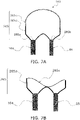
- a drainage mechanism 260 may adopt a container 265 shown in FIG. 7A and FIG. 7B .
- the drainage mechanism 260 is a drainage mechanism that adopts the container 265 instead of the container 165 of the drainage mechanism 160.
- the container 265 includes a less rigid rubber upper portion 265c and a more rigid lower portion 265d. At a lower end of the lower portion 265d, two connecting ports are formed, a first end 265a to which a copper pipe as the first flow path 164 is connected, and a second end 265b to which a copper pipe as the second flow path 68 is connected.
- the upper portion 265c of the container 265 closes the internal flow path of the container 265 by elastic deformation thereof, as shown in FIG. 7B .
- the drainage mechanism 260 can also suppress the phenomenon that the drain water flows backward from the second flow path 68 to the first flow path 164 via the container 265.
- the drainage mechanism 160 of the second embodiment adopts the container 165 including a soft material such as rubber.
- the entire container may include a highly rigid material such as resin or metal.
- a drainage mechanism 500 of the third embodiment is a mechanism for causing drain water (condensate) discharged from an air conditioning indoor unit 12 installed near a ceiling 91 to flow to the outside a building or in a drain ditch of the building.
- the drainage mechanism 500 is connected to a drain pump 59, which sucks the drain water from a drain pan 57 in the air conditioning indoor unit 12.
- the drainage mechanism 500 includes a connecting part 520 connected to a connecting port 59a of the drain pump 59, a third flow path 530, a fourth flow path 540, a fifth flow path 550, a sixth flow path 560, a seventh flow path 570, and an eighth flow path 580.
- the connecting part 520 of the drainage mechanism 500 mainly includes a polyvinyl chloride pipe 521 fitted into the connecting port 59a of the drain pump 59, a small-diameter copper pipe 522 connected to the polyvinyl chloride pipe 521, and an elbow 523 that forms flared connection to the small-diameter copper pipe 522.
- the small-diameter copper pipe 522 is a copper pipe having an outer diameter of 9.52 mm and a wall thickness of 0.8 mm. In this specification, the copper pipe having these outer diameter and wall thickness is referred to as small-diameter copper pipe.
- the small-diameter copper pipe is a copper pipe with a nominal diameter (JRA) of sanbu in Japan.
- the inner diameter of the small-diameter copper pipe is about 7.9 mm.
- the elbow 523 is also a copper joint having an outer diameter of 9.52 mm and a wall thickness of 0.8 mm.
- the U-shaped third flow path 530, the fourth flow path 540, and the fifth flow path 550 shown in FIG. 8 are one large-diameter copper pipe.
- the U-shaped large-diameter copper pipe is a copper pipe having an outer diameter of 22.22 mm and a wall thickness of about 1 mm. In this specification, the copper pipe having these outer diameter and wall thickness is referred to as large-diameter copper pipe.
- the large-diameter copper pipe is a copper pipe with a nominal diameter (JRA) of nanabu in Japan.
- An inner diameter of the large-diameter copper pipe is about 20 mm.
- the third flow path 530 is a part of the U-shaped large-diameter copper pipe extending upward from the connecting part 520.
- the fourth flow path 540 is a part of the U-shaped large-diameter copper pipe that changes the direction of water flowing inside from upward to downward.
- the fourth flow path 540 includes a first end 541 and a second end 542.
- the first end 541 is connected to an upper end of the third flow path 530.
- the second end 542 is located on the opposite side of the first end 541.
- the fifth flow path 550 is a part of the U-shaped large-diameter copper pipe extending downward from the second end 542 of the fourth flow path 540.
- a height direction distance H4 of 200 mm or more between a highest point of a center line of an internal flow path of the fourth flow path 540 and the connecting port 59a of the drain pump 59 to which the connecting part 520 is connected (see FIG. 8 ).
- the drainage mechanism 500 is installed such that the distance H4 is 250 to 500 mm.
- the copper pipe as the sixth flow path 560, the seventh flow path 570, and the eighth flow path 580 is the above-described small-diameter copper pipe.
- the sixth flow path 560, the seventh flow path 570, and the eighth flow path 580 including one or more small-diameter copper pipes are manually curved in a space 90 under the roof by an installer to avoid a beam or the like existing in the space 90 under the roof of the building.
- the sixth flow path 560, the seventh flow path 570, and the eighth flow path 580 are finally connected to a collecting pipe for discharge 70, which discharges the drain water to the outside of the building, while changing the height position at each portion. Since the drain pump 59 sends the drain water under pressure, it is not necessary to install the small-diameter copper pipe as the sixth flow path 560, the seventh flow path 570, and the eighth flow path 580 in consideration of gradient.
- the sixth flow path 560 extends from a lower part of the fifth flow path 550.
- a flow path area of the sixth flow path 560 which is a small-diameter copper pipe, is about 49 mm 2 because the inner diameter is 7.9 mm.
- the flow path area of the large-diameter copper pipe including the fourth flow path 540 and the fifth flow path 550 is about 314 mm 2 because the inner diameter is about 20 mm.
- the inner diameter of the fourth flow path 540 and the fifth flow path 550 is about 20 mm, which is larger than the inner diameter of the sixth flow path of 7.9 mm, and is about 2.5 times the inner diameter of the sixth flow path of 7.9 mm.
- the seventh flow path 570 is part of the small-diameter copper pipe that is continuous with the sixth flow path 560.
- the seventh flow path 570 is located between the sixth flow path 560 and the eighth flow path 580.
- a height position H570 of a lowest point 570a having the lowest height out of a center line of an internal flow path of the seventh flow path 570 is lower than any point of a center line of an internal flow path of the sixth flow path 560.
- the height position H570 of the lowest point 570a of the seventh flow path 570 is lower than a height position H57 of an upper end of the drain pan 57.
- a height position of any point of a center line of an internal flow path of the eighth flow path 580 is, as shown in FIG. 8 , higher than the height position H570 of the lowest point 570a of the seventh flow path 570.
- the eighth flow path 580 is located between the collecting pipe for discharge 70 that discharges the drain water to the outside of the building and the seventh flow path 570.
- the lowest point 570a of the seventh flow path 570 is the lowest point out of the center line of the internal flow path of the small-diameter copper pipe extending from a lower part of the fifth flow path 550 (sixth flow path 560, seventh flow path 570, and eighth flow path 580).
- the eighth flow path 580 is connected to a branch pipe extending from the collecting pipe for discharge 70 via a flare connecting part 581.
- the eighth flow path 580 is preferably 2 to 4 m long.
- the sixth flow path 560 and the like is a small-diameter copper pipe, and therefore is flexible. This makes it easy to construct and install the sixth flow path 560, the seventh flow path 570, and the eighth flow path 580 while avoiding obstacles in the space 90 under the roof.
- the sixth flow path 560, the seventh flow path 570, and the eighth flow path 580 which are a small-diameter copper pipe having an inner diameter of 7.9 mm and a flow path area of about 49 mm 2 , are often filled (sealed) with the drain water.
- the drain water continues to be sent under pressure, with the sixth flow path 560, the seventh flow path 570, and the eighth flow path 580 filled with the drain water.
- the drain pump 59 stops the water that has flowed from the third flow path 530 to the sixth flow path 560 will flow backward.
- the drainage mechanism 500 has a configuration in which the fourth flow path 540 is provided to change the direction of the drain water that is sent under pressure by the drain pump 59 from upward to downward, the fifth flow path 550 extends downward from the second end 542 of the fourth flow path 540, and the sixth flow path 560 further extends from the fifth flow path 550. Since the flow path area of the fourth flow path 540 and the fifth flow path 550 (about 314 mm 2 ) is larger than the flow path area of the sixth flow path 560 (about 49 mm 2 ), entrapped air is formed in at least one of the fourth flow path 540 and the fifth flow path 550.
- entrapped air of about 50 cc is generated from the fourth flow path 540 to the fifth flow path 550.
- the entrapped air is a space filled with air in the fourth flow path 540 and the fifth flow path 550.
- the drainage mechanism 500 is provided with the seventh flow path 570 having the center line including the lowest point 570a with the height position lower than the height position H57 of the upper end of the drain pan 57.
- the small-diameter copper pipe (the sixth flow path 560, the seventh flow path 570, the eighth flow path 580) extending from the U-shaped large-diameter copper pipe toward the collecting pipe for discharge 70 is laid under the roof, a trap is made such that part of the small diameter pipe is lower than the height position H57 of the upper end of the drain pan 57.
- the seventh flow path 570 acts as the so-called trap.
- the seventh flow path 570 is provided, even if the drain pump 59 stops, some of the water in the connecting part 520 or the third flow path 530 falls to the drain pan 57 side, and the entrapped air in the fourth flow path 540 or the fifth flow path 550 moves a little to the drain pan 57 side, it is possible to secure a sufficient height direction distance between the entrapped air and the lowest point 570a of the seventh flow path 570. This makes it possible to prevent the phenomenon that the water existing in the small-diameter copper pipe (the sixth flow path 560, the seventh flow path 570, the eighth flow path 580) also flows backward to the drain pan 57.
- the small-diameter copper pipe (the sixth flow path 560, the seventh flow path 570, the eighth flow path 580) is laid such that the height position H570 of the lowest point 570a of the seventh flow path 570 is lower than the height position H57 of the upper end of the drain pan 57.
- the height direction distance between the entrapped air in the U-shaped large-diameter pipe and the lowest point 570a of the seventh flow path 570 is preferably set as large as possible. Therefore, the lowest point 570a of the seventh flow path 570 is preferably lowered to a position lower than the height position of the lower end of the drain pan 57, furthermore to a position lower than the height position of a lower surface of the air conditioning indoor unit 12.
- the third flow path 530, the fourth flow path 540, and the fifth flow path 550 are formed by the U-shaped large-diameter copper pipe.
- the fourth flow path 540 and the fifth flow path 550 may be formed by the large-diameter copper pipe and the third flow path 530 may be formed by the small-diameter copper pipe.
- entrapped air is formed in at least one of the fourth flow path 540 and the fifth flow path 550, suppressing the backflow of water from the sixth flow path 560.
- the eighth flow path 580 is provided between the seventh flow path 570 including the lowest point 570a and the collecting pipe for discharge 70.
- the eighth flow path 580 extends diagonally upward from the seventh flow path 570, as shown in FIG. 8 .
- a configuration may be adopted in which the seventh flow path 570 extends horizontally long from the lowest point 570a and is connected to the collecting pipe for discharge 70.
- the size of the drain pan 57 of the air conditioning indoor unit 12 is not mentioned.
- the relationship between the size of the drain pan 57 and the size of the drain pump 59 and the connecting part 520 to the fourth flow path 540 of the drainage mechanism 500 is preferably a magnitude relationship described below.
- volume Q is a volume of a space of the internal space of the drain pan 57 that contains no drain water and is open to the atmosphere. It can be said that the volume Q is the maximum volume that can hold the backflow drain water in the drain pan 57 when the drain water flows backward from the drainage mechanism 500 and returns to the drain pan 57.
- the volume V is the total volume of the internal volume of the drain pump 59, the internal volume of the connecting part 520 of the drainage mechanism 500, the internal volume of the third flow path 530, and the volume of a portion that is lower than the height position of the top (highest point) of a flow path lower surface 540B of the fourth flow path 540 and continuous with the third flow path 530, out of the internal volume of the fourth flow path 540.
- the third flow path 530, the fourth flow path 540, and the fifth flow path 550 are formed by the U-shaped large-diameter copper pipe.
- a drainage mechanism 600 that adopts a third flow path 630, a fourth flow path 640, and a fifth flow path 650 shown in FIG. 10 may be connected to the drain pump 59.
- the drainage mechanism 600 shown in FIG. 10 may be connected to the drain pump 59.
- volume Q the volume of a portion located above the water level of the drain pan 57 when the drain pump 59 is operating (height position of drain suction port 59B of drain pump 59) and located below the height position of the upper end 57T of the side wall of the drain pan 57 is defined as volume Q.
- the volume Q exceeds the volume V1 shown in FIG. 10 in modification 3D.
- the sizes of the drain pump 59 and the connecting part 520 to the third flow path 630 of the drainage mechanism 600 and the shape of a connecting part 640 are determined such that the volume V1 is less than the volume Q.
- the volume V1 is the total volume of the internal volume of the drain pump 59, the internal volume of the connecting part 520 of the drainage mechanism 600, the internal volume of the third flow path 630, and the volume of a portion that is lower than the height position of the highest point of the flow path lower surface of the fourth flow path 640 and continuous with the third flow path 630 out of the internal volume of the fourth flow path 640.
- each of the parts 59, 520, 630, and 650 are determined such that, out of the internal space of the fifth flow path 650 of the drainage mechanism 600, the volume V2 of the part indicated by hatching in FIG. 10 is larger than the volume V1.
- Out of the internal space of the fifth flow path 650, the part indicated by hatching in FIG. 10 is a space which is not a flow path for drain water and in which air is accumulated, in a state where the drain pump 59 is operating and the drain water is drained from the drain pan 57 to the drainage mechanism 600. Since the volume V2 of this space is larger than the volume VI, even if a backflow occurs from the drainage mechanism 600 to the drain pan 57, the situation where the drain water overflows from the drain pan 57 rarely occurs.
- Patent Literature 1 Japanese Laid-Open Patent Application No. H5-203177
Landscapes
- Engineering & Computer Science (AREA)
- Chemical & Material Sciences (AREA)
- Combustion & Propulsion (AREA)
- Mechanical Engineering (AREA)
- General Engineering & Computer Science (AREA)
- Physics & Mathematics (AREA)
- Thermal Sciences (AREA)
- Devices For Blowing Cold Air, Devices For Blowing Warm Air, And Means For Preventing Water Condensation In Air Conditioning Units (AREA)
Abstract
Description
- The present disclosure relates to a drainage mechanism, in particular to a drainage mechanism connected to a drain pump that sucks water from a drain pan of an air conditioning indoor unit. In addition, the present disclosure relates to an air conditioning system including the drainage mechanism.
- A technique of drainage with a pump is described in Patent Literature 1 (
Japanese Laid-Open Patent Application No. H5-203177 - However, even if a structure such as Patent Literature 1 (
Japanese Laid-Open Patent Application No. H5-203177 Japanese Laid-Open Patent Application No. H5-203177 - A drainage mechanism of a first aspect is connected to a drain pump that sucks water from a drain pan. The drain pan receives water in an air conditioning indoor unit. The drainage mechanism includes a connecting part connected to the drain pump, a first flow path, a folded part, and a second flow path. The first flow path extends upward from the connecting part. The folded part includes a first end connected to an upper end of the first flow path and a second end on the opposite side of the first end. The folded part changes the direction of water flowing inside from upward to downward. The second flow path extends from the second end of the folded part. The second flow path is a pipe having an inner diameter of 13 mm or less. A flow path area of the folded part is larger than a flow path area of the second flow path.
- The drainage mechanism of the first aspect has a configuration in which the folded part is provided to change the direction of water from upward to downward, and the second flow path extends from the second end of the folded part. Since the flow path area of the folded part is larger than the flow path area of the second flow path, entrapped air is likely to be formed in the folded part. If entrapped air exists in the folded part, even if the drain pump stops, the backflow of the water that has flowed from the first flow path to the second flow path via the folded part is suppressed. In other words, with the drainage mechanism of the first aspect, the problem that the drain water returns to the drain pan of the air conditioning indoor unit is unlikely to occur.
- Note that the second flow path is a pipe having an inner diameter of 13 mm or less, providing flexibility and, for example, allowing easy construction and installation while avoiding obstacles in a space under the roof.
- The drainage mechanism of the second aspect is the drainage mechanism of the first aspect, in which the second flow path includes a metal or resin pipe including a curved part.
- Here, as the second flow path, for example, a resin flexible hose is adopted and installed while avoiding obstacles, a copper pipe is adopted, or a polyvinyl chloride pipe or joint is adopted. Adoption of these pipes including the curved part allows the second flow path to be easily laid even in the narrow space under the roof or the like with many obstacles.
- The drainage mechanism of the third aspect is the drainage mechanism of the first aspect or the second aspect, in which the second flow path includes a copper pipe.
- Here, the copper pipe having an inner diameter of 13 mm or less is adopted as the second flow path, making it further easier to lay the second flow path.
- The drainage mechanism of the fourth aspect is the drainage mechanism of any one of the first aspect to the third aspect, in which a flow path area of the first flow path is larger than the flow path area of the second flow path.
- Here, the flow path area of the first flow path connecting the connecting part to the folded part is larger than the flow path area of the second flow path. This smooths the flow of water from the drain pump to the folded part.
- The drainage mechanism of the fifth aspect is the drainage mechanism of the fourth aspect, in which the flow path area of the first flow path is equal to the flow path area of the folded part. The first flow path and the folded part are continuous.
- Here, the first flow path and the folded part are continuous and have the same flow path area. With this configuration, for example, part of one flexible hose can be used as the first flow path, and the rest of the flexible hose can be used as the folded part. In this case, the number of parts can be reduced. This also simplifies the construction work.
- The drainage mechanism of the sixth aspect is the drainage mechanism of any one of the first aspect to the third aspect, in which a flow path area of the first flow path is smaller than the flow path area of the folded part.
- Here, since the first flow path having a smaller flow path area than the folded part is adopted, for example, bending the first flow path for construction makes it possible to install the folded part at a desired location away from the air conditioner. There is also the merit that the cost can be reduced when the first flow path is long.
- The drainage mechanism of the seventh aspect is the drainage mechanism of any one of the first aspect to the sixth aspect, in which the highest point of the folded part is higher than the highest point of the first flow path, and is higher than the highest point of the second flow path. The highest point of the folded part is a point with a highest height out of a center line of an internal flow path of the folded part. The highest point of the first flow path is a point with a highest height out of a center line of an internal flow path of the first flow path. The highest point of the second flow path is a point with a highest height out of a center line of an internal flow path of the second flow path.
- The drainage mechanism of the eighth aspect is the drainage mechanism of any one of the first aspect to the seventh aspect, in which a height direction distance between the highest point with the highest height out of the center line of the internal flow path of the folded part and the connecting part is 200 to 500 mm.
- Here, the highest point of the folded part is placed at a position 200 mm or more higher than the connecting part connected to the drain pump. This suppresses the backflow of water from the second flow path to the first flow path more reliably. Here, the height of the highest point of the folded part is set to be 500 mm higher than the connecting part, or is set to be lower than the
position 500 mm higher than the connecting part. In this way, since the height of the folded part is not unnecessarily increased, the capacity of the drain pump can be reduced. - The drainage mechanism of the ninth aspect is the drainage mechanism of any one of the first aspect to the eighth aspect, in which a height direction distance between the highest point with the highest height out of the center line of the internal flow path of the folded part and the second end is 50 to 700 mm.
- Here, the distance between the highest point of the folded part and the second end is secured at 50 mm or more. This suppresses the backflow of water from the second flow path to the first flow path more reliably. Here, the distance between the highest point of the folded part and the second end is set to 700 mm or less. This prevents the constraint on the installation of the second flow path extending from the second end from becoming too large. If the height position of the second end becomes low, it becomes difficult to install the second flow path.
- The drainage mechanism of the tenth aspect is the drainage mechanism of any one of the first aspect to the ninth aspect, in which the folded part includes a container.
- Here, a container is adopted as the folded part, instead of a pipe. This makes it easy to increase the flow path area or the internal volume of the folded part. This makes it easy for entrapped air to exist in the folded part.
- The drainage mechanism of the eleventh aspect is the drainage mechanism of the tenth aspect, in which the container includes an elastic member. The elastic member closes the internal flow path of the container by elastic deformation.
- Here, even if the drain pump stops, the internal pressure of the folded part drops, and the entrapped air of the folded part shrinks due to the pressure drop, the elastic member closes the internal flow path. This suppresses the backflow of water from the second flow path to the first flow path via the folded part.
- The drainage mechanism of the twelfth aspect is the drainage mechanism of the tenth aspect, in which the container includes a switching member. The switching member switches between a communication state and a non-communication state of an internal space and an external space. When the pressure of the internal space of the container drops to less than a predetermined value, the switching member switches from the non-communication state to the communication state to take in the air in the external space of the container into the internal space of the container.
- Here, even if the drain pump stops and the internal pressure of the folded part drops, when the pressure drops to less than the predetermined value, the switching member switches from the non-communication state to the communication state. This causes the air in the external space of the container to be taken into the internal space of the container, increasing the pressure inside the folded part. Therefore, the drainage mechanism of the twelfth aspect can easily suppress the backflow of water from the second flow path to the first flow path via the folded part.
- The drainage mechanism of the thirteenth aspect is connected to a drain pump that sucks water from a drain pan receiving the water in an air conditioning indoor unit. The drainage mechanism includes a connecting part connected to the drain pump, a third flow path, a fourth flow path, a fifth flow path, and a sixth flow path. The third flow path extends upward from the connecting part. The fourth flow path includes a first end and a second end. The first end is connected to an upper end of the third flow path. The second end is located on the opposite side of the first end. The fourth flow path changes the direction of water flowing inside from upward to downward. The fifth flow path extends downward from the second end of the fourth flow path. The sixth flow path extends from the fifth flow path. The sixth flow path is a pipe having an inner diameter of 13 mm or less. A flow path area of the fourth flow path and/or the fifth flow path is larger than a flow path area of the sixth flow path.
- The drainage mechanism of the thirteenth aspect has a configuration in which the fourth flow path is provided to change the direction of water from upward to downward, the fifth flow path extends from the second end of the fourth flow path, and the sixth flow path extends from the fifth flow path. Since the flow path area of the fourth flow path and/or the fifth flow path is larger than the flow path area of the sixth flow path, entrapped air is likely to be formed in the fourth flow path and/or the fifth flow path. If entrapped air exists in the fourth flow path and/or the fifth flow path, even if the drain pump stops, the backflow of water that has flowed from the third flow path to the sixth flow path is suppressed. In other words, with the drainage mechanism of the thirteenth aspect, the problem that the drain water returns to the drain pan of the air conditioning indoor unit is unlikely to occur.
- Note that the sixth flow path is a pipe having an inner diameter of 13 mm or less, providing flexibility and, for example, allowing easy construction and installation while avoiding obstacles in a space under the roof.
- The drainage mechanism of the fourteenth aspect is the drainage mechanism of the thirteenth aspect, in which the fourth flow path and the fifth flow path are one pipe and are continuous.
- The drainage mechanism of the fifteenth aspect is the drainage mechanism of the fourteenth aspect, in which the fourth flow path and the fifth flow path are one copper pipe. An inner diameter of the fourth flow path and the fifth flow path is larger than an inner diameter of the sixth flow path.
- The drainage mechanism of the sixteenth aspect is the drainage mechanism of any one of the thirteenth aspect to the fifteenth aspect, in which the sixth flow path includes one or more copper pipes.
- Here, since one or more copper pipes having an inner diameter of 13 mm or less is used as the sixth flow path, it is further easier to lay the sixth flow path.
- The drainage mechanism of the seventeenth aspect is the drainage mechanism of the fourteenth aspect or the fifteenth aspect, in which the inner diameter of the fourth flow path and the fifth flow path is 1.5 times or more the inner diameter of the sixth flow path.
- Here, by adopting pipes with different inner diameters as the fourth flow path and the fifth flow path, and the sixth flow path, the flow path area of the fourth flow path and/or the fifth flow path is larger than the flow path area of the sixth flow path.
- Note that the inner diameter of the fourth flow path and the fifth flow path is preferably 1.5 times or more the inner diameter of the sixth flow path, and more preferably twice or more the inner diameter of the sixth flow path. In this case, the cost of the drainage mechanism is a little higher, but the degree of suppression of the backflow of water is further increased.
- The drainage mechanism of the eighteenth aspect is the drainage mechanism of any one of the thirteenth aspect to the seventeenth aspect, further including a seventh flow path continuous with the sixth flow path. The sixth flow path is located between the fifth flow path and the seventh flow path. A height position of a lowest point with a lowest height out of a center line of an internal flow path of the seventh flow path is at a position lower than any point of a center line of an internal flow path of the sixth flow path. The height position of the lowest point with the lowest height out of the center line of the internal flow path of the seventh flow path is at a position lower than a height position of an upper end of the drain pan.
- Here, the seventh flow path having the center line including the lowest point lower than the height position of the upper end of the drain pan is provided. With this configuration, when the backflow of water is suppressed by causing entrapped air to exist in the fourth flow path and/or the fifth flow path, the height direction distance between the entrapped air and the lowest point of the seventh flow path can be increased.
- The drainage mechanism of the nineteenth aspect is the drainage mechanism of the eighteenth aspect, further including an eighth flow path continuous with the seventh flow path. A height position of any point of a center line of an internal flow path of the eighth flow path is higher than the height position of the lowest point of the seventh flow path. The eighth flow path is located between a discharge flow path for discharging the water to an outside and the seventh flow path.
- The drainage mechanism of the twentieth aspect is the drainage mechanism of any one of the thirteenth aspect to the nineteenth aspect, in which a total volume of an internal volume of the drain pump, an internal volume of the connecting part, an internal volume of the third flow path, and a volume of a portion that is lower than a height position of a highest point of a flow path lower surface of the fourth flow path and continuous with the third flow path out of an internal volume of the fourth flow path is smaller than a volume of a space higher than a water level of the drain pan when the drain pump is operating out of an internal space of the drain pan.
- The air conditioning system includes the air conditioning indoor unit, the drain pump, and the drainage mechanism. The air conditioning indoor unit includes the drain pan and a heat exchanger disposed above the drain pan. The drain pump sucks water from the drain pan. The drainage mechanism is the drainage mechanism according to any one of the first aspect to the twentieth aspect and is connected to the drain pump.
-
-
FIG. 1 is a diagram showing a refrigerant circuit of an air conditioning apparatus including an air conditioning indoor unit to which a drainage mechanism is connected, and the like. -
FIG. 2 is a schematic diagram showing the air conditioning indoor unit and the drainage mechanism of a first embodiment to be disposed in a space under the roof. -
FIG. 3A is a schematic diagram of the air conditioning indoor unit and the drainage mechanism of the first embodiment. -
FIG. 3B is an enlarged view of the drainage mechanism shown inFIG. 3A . -
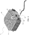
FIG. 4 is a perspective view of the air conditioning indoor unit and the drainage mechanism of the first embodiment. -
FIG. 5 is a schematic diagram of a drainage mechanism of a second embodiment. -
FIG. 6 is a schematic diagram of a container of the drainage mechanism of the second embodiment. -
FIG. 7A is a schematic diagram showing one state of the container of the drainage mechanism of modification 2A of the second embodiment. -
FIG. 7B is a schematic diagram showing another state of the container of the drainage mechanism of modification 2A of the second embodiment. -
FIG. 8 is a schematic diagram of an air conditioning indoor unit and a drainage mechanism of a third embodiment. -
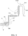
FIG. 9 is a schematic diagram of the drainage mechanism of modification 3C of the third embodiment. -
FIG. 10 is a schematic diagram of the drainage mechanism of modification 3D of the third embodiment. - A drainage mechanism described below is connected to an air conditioning indoor unit of an air conditioning apparatus, especially to a ceiling-mounted air conditioning indoor unit. The
air conditioning apparatus 10 and the air conditioningindoor unit 12 are installed in a building and then form an air conditioning system together with the drainage mechanism. - As shown in
FIG. 1 , theair conditioning apparatus 10 is a refrigerant pipe-scheme decentralized air conditioning apparatus, and heats and cools each room in the building by executing a vapor compression refrigeration cycle operation. Theair conditioning apparatus 10 includes an air conditioningoutdoor unit 11, a large number of air conditioningindoor units 12, and a liquid-refrigerant connection pipe 13 and a gas-refrigerant connection pipe 14 serving as refrigerant connection pipes connecting the air conditioningoutdoor unit 11 to the air conditioningindoor units 12. A refrigerant circuit of theair conditioning apparatus 10 shown inFIG. 1 is configured by connection of the air conditioningoutdoor unit 11, the air conditioningindoor units 12, and therefrigerant connection pipes 13 and 14. A refrigerant is sealed in the refrigerant circuit shown inFIG. 1 . Theair conditioning apparatus 10 executes the refrigeration cycle operation in which the refrigerant is compressed, cooled and condensed, decompressed, heated and evaporated, and then compressed again. - The air conditioning
outdoor unit 11 is installed outside a building, in a basement of a building, or the like, and is connected to the air conditioningindoor units 12 via therefrigerant connection pipes 13 and 14. The air conditioningoutdoor unit 11 mainly includes acompressor 20, a four-way switching valve 15, anoutdoor heat exchanger 30, anoutdoor expansion valve 41, anoutdoor fan 35, a liquid-side shutoff valve 17, and a gas-side shutoff valve 18. - Each of the air conditioning
indoor units 12 is installed on aceiling 91 of each room as shown inFIG. 2 , and is connected to the air conditioningoutdoor unit 11 via therefrigerant connection pipes 13 and 14. The air conditioningindoor unit 12 mainly includes anindoor expansion valve 42, anindoor heat exchanger 50, anindoor fan 55, adrain pan 57, and adrain pump 59. - The
indoor heat exchanger 50 is a heat exchanger that functions as a refrigerant evaporator or condenser. One end of theindoor heat exchanger 50 is connected to theindoor expansion valve 42, and the other end thereof is connected to the gas-refrigerant connection pipe 14. - During cooling operation when the
indoor heat exchanger 50 functions as an evaporator, condensate is generated on a surface of theindoor heat exchanger 50. Thedrain pan 57 is installed to receive the condensate. - The condensate that has flowed down to the
drain pan 57 is discharged by thedrain pump 59 to the outside of the air conditioningindoor unit 12 as drain water. A connectingport 59a is provided on a discharge side of thedrain pump 59. A connectingpart 62a of adrainage mechanism 60, which will be described later, is connected to the connectingport 59a. The connectingport 59a is a tip opening of a copper pipe protruding from a side plate of acasing 12a of the air conditioningindoor unit 12. - The
drain pump 59 is a pump that applies pressure on the drain water and sends the drain water to thedrainage mechanism 60. - The
refrigerant connection pipes 13 and 14 are refrigerant pipes that will be constructed on the spot when the air conditioningoutdoor unit 11 and the air conditioningindoor units 12 are installed in the building. As shown inFIG. 2 , therefrigerant connection pipes 13 and 14 also pass through aspace 90 under the roof in the same manner as thedrainage mechanism 60 described later. - As shown in
FIG. 2 andFIG. 3A , thedrainage mechanism 60 of the first embodiment is a mechanism for causing the drain water (condensate) discharged from the air conditioningindoor units 12 installed near theceiling 91 to flow to the outside the building or in a drain ditch of the building. Thedrainage mechanism 60 is connected to thedrain pump 59, which sucks the drain water from thedrain pan 57 in the air conditioningindoor unit 12. Thedrainage mechanism 60 includes the connectingpart 62a connected to the connectingport 59a of thedrain pump 59, afirst flow path 64, a foldedpart 65, and asecond flow path 68. - The connecting
part 62a of thedrainage mechanism 60 is one end of anelbow 62, which is a joint, as shown inFIG. 3A andFIG. 3B . Aflexible hose 63 is connected to the other upward end of theelbow 62. - The
flexible hose 63 is a hose having a heat insulating function in which thefirst flow path 64 extending straight upward from theelbow 62 and the foldedpart 65 including a curved part are continuous. The foldedpart 65 includes afirst end 65a connected to an upper end of thefirst flow path 64 and asecond end 65b on the opposite side of thefirst end 65a. The foldedpart 65 changes the direction of the drain water flowing inside from upward to downward. Thesecond end 65b of the foldedpart 65 is a connecting port at a lower end of acoupling 66 connected to the tip of theflexible hose 63. Note that in the present embodiment, thefirst end 65a is a boundary between the continuousfirst flow path 64 and the foldedpart 65. - The flow path area of the
first flow path 64 of theflexible hose 63 is equal to the flow path area of the foldedpart 65. A flow path area of thefirst flow path 64 and the foldedpart 65 is larger than a flow path area of the second flow path 68 (copper pipe) described later. An inner diameter of theflexible hose 63 is about 19 mm. - The
second flow path 68 extending downward from thesecond end 65b of the foldedpart 65 is a copper pipe including acurved part 68c. An inner diameter of the copper pipe as thesecond flow path 68 is 13 mm or less. Here, as thesecond flow path 68, a copper pipe having an outer diameter of 12.7 mm, an inner diameter of 11.1 mm, and a wall thickness of 0.8 mm is used. - The copper pipe as the
second flow path 68 is manually curved in thespace 90 under the roof by an installer of theair conditioning apparatus 10 to avoid abeam 93 or the like existing in thespace 90 under the roof of the building as shown inFIG. 2 . Thesecond flow path 68 is finally connected to a collecting pipe fordischarge 70, which discharges the drain water to the outside of the building (seeFIG. 3A ), while changing the height position at each portion. Since thedrain pump 59 sends the drain water under pressure, it is not necessary to install the copper pipe as thesecond flow path 68 in consideration of gradient. - However, since too long distance to the collecting pipe for
discharge 70 will exceed the capacity of thedrain pump 59, the copper pipe as thesecond flow path 68 is preferably 20 m or less long. - The copper pipe as the
second flow path 68 preferably includes avertical pipe portion 68a extending downward from thesecond end 65b and ahorizontal pipe portion 68b extending horizontally from thevertical pipe portion 68a. Thevertical pipe portion 68a preferably secures some length. A size H3 related to the length of thevertical pipe portion 68a will be described below. - In the
drainage mechanism 60, as shown inFIG. 3B , ahighest point 65T of the foldedpart 65 is higher than ahighest point 64T of thefirst flow path 64, and is higher than ahighest point 68T of thesecond flow path 68. Thehighest point 65T of the foldedpart 65 is the highest point of acenter line 65C of an internal flow path of the foldedpart 65. Thehighest point 64T of thefirst flow path 64 is the highest point of acenter line 64C of an internal flow path of thefirst flow path 64. Thehighest point 68T of thesecond flow path 68 is the highest point of acenter line 68C of an internal flow path of thesecond flow path 68. - In the
drainage mechanism 60, sizes HI, H2, and H3 shown inFIG. 3B are determined to be - H1 = 200 to 500 mm
- H2 = 50 to 700 mm
- H3 < (HI - 100) mm,
- respectively. The size H1 is a height direction distance between the
highest point 65T of the foldedpart 65 and the center of the connectingpart 62a. The size H2 is a height direction distance between thehighest point 65T of the foldedpart 65 and thesecond end 65b. The size H3 is a height direction distance between thehighest point 65T of the foldedpart 65 and a center line of an internal flow path of thehorizontal pipe portion 68b of thesecond flow path 68. - A portion beyond the
horizontal pipe portion 68b of the copper pipe as thesecond flow path 68 is installed in a space lower than the height position of thehorizontal pipe portion 68b. The copper pipe does not have to be downhill until the collecting pipe fordischarge 70, but in a range from thehorizontal pipe portion 68b to the collecting pipe fordischarge 70, the copper pipe is installed in thespace 90 under the roof such that the copper pipe does not rise to a space higher than the height position of thehorizontal pipe portion 68b. - (3-1) The
drainage mechanism 60 has a configuration in which the foldedpart 65 is provided to change the direction of the drain water sent by thedrain pump 59 under pressure from upward to downward, and the copper pipe as thesecond flow path 68 extends from thesecond end 65b of the foldedpart 65. Since the flow path area of the foldedpart 65 is larger than the flow path area of thesecond flow path 68, entrapped air is likely to be formed in the foldedpart 65. If entrapped air exists in the foldedpart 65, even if thedrain pump 59 stops, the backflow of the condensate that has flowed from thefirst flow path 64 to thesecond flow path 68 via the foldedpart 65 is suppressed. In other words, in thedrainage mechanism 60, the problem that the drain water returns to thedrain pan 57 of the air conditioningindoor unit 12 is unlikely to occur. - Note that the entrapped air is a space filled with air in the folded
part 65. The flow path area is an average of the flow path areas in respective parts when the parts are cut by a plane orthogonal to the direction of water flow. The flow path area of thesecond flow path 68, which is a copper pipe, is an area calculated from the inner diameter of the copper pipe. - (3-2) In the
drainage mechanism 60, the inner diameter of the copper pipe as thesecond flow path 68 is 13 mm or less. This copper pipe is flexible and, as shown inFIG. 2 , can be constructed and installed in thespace 90 under the roof while avoiding obstacles such as thebeam 93. - (3-3) In the
drainage mechanism 60, the flow path area of thefirst flow path 64 is larger than the flow path area of thesecond flow path 68. Therefore, the flow path resistance until the foldedpart 65 is small, and the drain water flows smoothly from thedrain pump 59 to the foldedpart 65. The risk that the flow path is clogged between thedrain pump 59 and the foldedpart 65 is reduced. Therefore, when the flow path of thedrainage mechanism 60 is clogged, only the copper pipe as thesecond flow path 68 needs maintenance. - (3-4) The
drainage mechanism 60 adopts theflexible hose 63, in which thefirst flow path 64 and the foldedpart 65 are integrated. This can reduce the number of parts. This also simplifies the construction work. There is also a merit of cost reduction in terms of parts procurement cost and construction cost. - (3-5) In the
drainage mechanism 60, thehighest point 65T of the foldedpart 65 is placed at a position 200 mm or more higher than the connectingpart 62a connected to thedrain pump 59. This suppresses the backflow of the drain water from thesecond flow path 68 to thefirst flow path 64 more reliably. - In the
drainage mechanism 60, the height of thehighest point 65T of the foldedpart 65 is set to be 500 mm higher than the connectingpart 62a, or is set to be lower than theposition 500 mm higher than the connectingpart 62a. In this way, since the height of the foldedpart 65 is not unnecessarily increased, the capacity of thedrain pump 59 can be suppressed. - (3-6) In the
drainage mechanism 60, the height direction distance between thehighest point 65T of the foldedpart 65 and thesecond end 65b (size H2) is 50 to 700 mm. - Here, the size H2 is secured at 50 mm or more. This suppresses the backflow of the drain water from the
second flow path 68 to thefirst flow path 64 more reliably. - Here, the size H2 is set to 700 mm or less. This prevents the constraint on the installation of the
second flow path 68 extending from thesecond end 65b from becoming too large. If the height position of thesecond end 65b becomes low, it becomes difficult to install thesecond flow path 68. - The
drainage mechanism 60 of the first embodiment adopts the copper pipe as thesecond flow path 68. Instead of the copper pipe, another metal pipe or a resin pipe may be adopted. - For example, as the
second flow path 68, a flexible hose smaller than theflexible hose 63 in flow path area may be adopted and installed while avoiding obstacles. As thesecond flow path 68, a polyvinyl chloride pipe and joint can also be adopted. Even if these pipes are adopted as thesecond flow path 68, thesecond flow path 68 can be easily laid even in thenarrow space 90 under the roof with many obstacles. - The
drainage mechanism 60 of the first embodiment uses theelbow 62 and thecoupling 66, but one end of theflexible hose 63 may be directly connected to the connectingport 59a of thedrain pump 59, or thesecond flow path 68 may be directly connected to the other end of theflexible hose 63. - The
drainage mechanism 60 of the first embodiment is a mechanism for causing the drain water (condensate) discharged from the air conditioningindoor units 12 installed near theceiling 91 to flow to the outside a building or in a drain ditch of the building. Meanwhile, thedrainage mechanism 60 can also be adopted as a mechanism that causes excess water discharged from a humidifier installed near the ceiling to flow to the outside of the building. - In the
drainage mechanism 60 of the first embodiment, a portion beyond thehorizontal pipe portion 68b of the copper pipe as thesecond flow path 68 is installed in a space lower than the height position of thehorizontal pipe portion 68b. However, thehorizontal pipe portion 68b may or may not be installed. - In the
drainage mechanism 60 of the first embodiment, in a range from thehorizontal pipe portion 68b to the collecting pipe fordischarge 70, the copper pipe is installed in thespace 90 under the roof such that the copper pipe does not rise to a space higher than the height position of thehorizontal pipe portion 68b. However, even if the copper pipe rises to a space higher than the height position of thehorizontal pipe portion 68b in order to avoid obstacles, or the like, if part of the copper pipe as thesecond flow path 68 passes through a lower position of thespace 90 under the roof, the problem that the drain water returns to thedrain pan 57 of the air conditioningindoor unit 12 can be suppressed. - The
drainage mechanism 60 of the first embodiment adopts theflexible hose 63 in which thefirst flow path 64 and the foldedpart 65 are integrated. Instead, adrainage mechanism 160 may adopt acontainer 165 and a copper pipe as afirst flow path 164 shown inFIG. 5 andFIG. 6 . - The
drainage mechanism 160 includes a copper pipe as a connectingpart 162 and thefirst flow path 164 connected to adrain pump 59, thecontainer 165 functioning as a folded part, and a copper pipe as asecond flow path 68. - The copper pipe as the connecting
part 162 and thefirst flow path 164, and the copper pipe as thesecond flow path 68 have the same size. The copper pipe as thefirst flow path 164 extends from a connecting port of thedrain pump 59 toward thecontainer 165 located above. A lower end of the copper pipe as thefirst flow path 164 is the connectingpart 162 connected to thedrain pump 59. The copper pipe as thesecond flow path 68 is the copper pipe similar to the copper pipe in the first embodiment. - The
container 165 is made of a soft material such as rubber to prevent the sound from reverberating. Thecontainer 165 plays a role of causing drain water to flow from thefirst flow path 164 to thesecond flow path 68 between the copper pipe as thefirst flow path 164 and the copper pipe as thesecond flow path 68, as shown inFIG. 6 . A flow path area of thecontainer 165 is larger than a flow path area of thefirst flow path 164 and thesecond flow path 68. An upper end of the copper pipe as thefirst flow path 164 inserted into thecontainer 165 is afirst end 165a of thecontainer 165. The upper end of the copper pipe as thefirst flow path 164 is at a position higher than an upper end of the copper pipe as thesecond flow path 68, suppressing the backflow of the drain water. The upper end of the copper pipe as thesecond flow path 68 inserted into thecontainer 165 is asecond end 165b of thecontainer 165. - Note that the flow path area of the
container 165 refers to the area inside thecontainer 165 when thecontainer 165 is cut by a plane orthogonal to the flow direction of the drain water flowing from thefirst end 165a to thesecond end 165b. As shown inFIG. 6 , the area inside thecontainer 165 is different between when cut near thefirst end 165a and when cut near thesecond end 165b. Here, an average of areas inside thecontainer 165 when cut by planes orthogonal to the flow direction of the drain water in thecontainer 165 is defined as the flow path area of thecontainer 165. - The
container 165 includes a switchingmember 165c. The switchingmember 165c is a flexible rubber member and switches between the communication state and non-communication state of an internal space of thecontainer 165 and an external space of thecontainer 165. When the pressure of the internal space of thecontainer 165 drops to less than a predetermined value, the switchingmember 165c switches from the non-communication state to the communication state to take in air in the external space of thecontainer 165 into the internal space of thecontainer 165. The switchingmember 165c shown inFIG. 6 is in the communication state. Note that when thedrain pump 59 is operating and the pressure of the internal space of thecontainer 165 is high, therubber switching member 165c is in the non-communication state, and the gap above the switchingmember 165c inFIG. 6 is closed. - The
container 165 includes a silencingmember 165d. The silencingmember 165d suppresses sound propagation between thefirst flow path 164 and thesecond flow path 68. The silencingmember 165d is curved in the opposite direction of a sound source, and has a high silencing effect. - An
inclined portion 165e is formed around thesecond end 165b of thecontainer 165. Theinclined portion 165e of thecontainer 165 is gently inclined to prevent the drain water from accumulating. - (3-1) The
drainage mechanism 160 adopts thecontainer 165 as the folded part instead of a pipe. Therefore, the flow path area and the internal volume of thecontainer 165 as the folded part are large. This causes large entrapped air to be generated in the internal space of thecontainer 165 that functions as the folded part. This suppresses the backflow of the condensate that has flown from thefirst flow path 164 to thesecond flow path 68 via thecontainer 165. - (3-2) The
drainage mechanism 160 adopts the first flow path 164 (copper pipe) having a smaller flow path area than thecontainer 165 functioning as the folded part. Therefore, bending the copper pipe as thefirst flow path 164 makes it possible to install thecontainer 165 at a desired location away from an air conditioningindoor unit 12. - (3-3) In the
drainage mechanism 160, thecontainer 165 includes the switchingmember 165c. Therefore, even if thedrain pump 59 stops and the internal pressure of thecontainer 165 drops, when the pressure drops to a predetermined value or less, the switchingmember 165c switches from the non-communication state to the communication state. This causes the air in the external space of thecontainer 165 to be taken into the internal space of thecontainer 165, increasing the pressure inside thecontainer 165. Therefore, in thedrainage mechanism 160, the phenomenon that the drain water flows backward due to the pressure drop in the entrapped air inside thecontainer 165 is less likely to occur. - (3-4) In the
drainage mechanism 160, thecontainer 165 includes the silencingmember 165d. In thedrainage mechanism 160, there is a risk of abnormal noise when the drain water passes under the influence of the entrapped air in thecontainer 165, but thecontainer 165 includes the silencingmember 165d, thereby making it possible to suppress the phenomenon of loud noise leaking into the space where the air conditioningindoor unit 12 is installed. - In the
drainage mechanism 160 of the second embodiment, thecontainer 165 is disposed between thefirst flow path 164 and thesecond flow path 68. Instead, adrainage mechanism 260 may adopt acontainer 265 shown inFIG. 7A and FIG. 7B . - The
drainage mechanism 260 is a drainage mechanism that adopts thecontainer 265 instead of thecontainer 165 of thedrainage mechanism 160. Thecontainer 265 includes a less rigid rubberupper portion 265c and a more rigidlower portion 265d. At a lower end of thelower portion 265d, two connecting ports are formed, afirst end 265a to which a copper pipe as thefirst flow path 164 is connected, and asecond end 265b to which a copper pipe as thesecond flow path 68 is connected. - The
upper portion 265c of thecontainer 265 closes the internal flow path of thecontainer 265 by elastic deformation thereof, as shown inFIG. 7B . With this configuration, even if thedrain pump 59 stops and the internal pressure of thecontainer 265 drops, the shape of thecontainer 265 changes to close the internal flow path. Therefore, thedrainage mechanism 260 can also suppress the phenomenon that the drain water flows backward from thesecond flow path 68 to thefirst flow path 164 via thecontainer 265. - The
drainage mechanism 160 of the second embodiment adopts thecontainer 165 including a soft material such as rubber. Instead, the entire container may include a highly rigid material such as resin or metal. - As shown in
FIG. 8 , adrainage mechanism 500 of the third embodiment is a mechanism for causing drain water (condensate) discharged from an air conditioningindoor unit 12 installed near aceiling 91 to flow to the outside a building or in a drain ditch of the building. Thedrainage mechanism 500 is connected to adrain pump 59, which sucks the drain water from adrain pan 57 in the air conditioningindoor unit 12. Thedrainage mechanism 500 includes a connectingpart 520 connected to a connectingport 59a of thedrain pump 59, athird flow path 530, afourth flow path 540, afifth flow path 550, asixth flow path 560, aseventh flow path 570, and aneighth flow path 580. - The connecting
part 520 of thedrainage mechanism 500 mainly includes apolyvinyl chloride pipe 521 fitted into the connectingport 59a of thedrain pump 59, a small-diameter copper pipe 522 connected to thepolyvinyl chloride pipe 521, and anelbow 523 that forms flared connection to the small-diameter copper pipe 522. The small-diameter copper pipe 522 is a copper pipe having an outer diameter of 9.52 mm and a wall thickness of 0.8 mm. In this specification, the copper pipe having these outer diameter and wall thickness is referred to as small-diameter copper pipe. The small-diameter copper pipe is a copper pipe with a nominal diameter (JRA) of sanbu in Japan. The inner diameter of the small-diameter copper pipe is about 7.9 mm. Theelbow 523 is also a copper joint having an outer diameter of 9.52 mm and a wall thickness of 0.8 mm. - The U-shaped
third flow path 530, thefourth flow path 540, and thefifth flow path 550 shown inFIG. 8 are one large-diameter copper pipe. The U-shaped large-diameter copper pipe is a copper pipe having an outer diameter of 22.22 mm and a wall thickness of about 1 mm. In this specification, the copper pipe having these outer diameter and wall thickness is referred to as large-diameter copper pipe. The large-diameter copper pipe is a copper pipe with a nominal diameter (JRA) of nanabu in Japan. An inner diameter of the large-diameter copper pipe is about 20 mm. - The
third flow path 530 is a part of the U-shaped large-diameter copper pipe extending upward from the connectingpart 520. Thefourth flow path 540 is a part of the U-shaped large-diameter copper pipe that changes the direction of water flowing inside from upward to downward. Thefourth flow path 540 includes afirst end 541 and asecond end 542. Thefirst end 541 is connected to an upper end of thethird flow path 530. Thesecond end 542 is located on the opposite side of thefirst end 541. Thefifth flow path 550 is a part of the U-shaped large-diameter copper pipe extending downward from thesecond end 542 of thefourth flow path 540. - It is preferable to secure a height direction distance H4 of 200 mm or more between a highest point of a center line of an internal flow path of the
fourth flow path 540 and the connectingport 59a of thedrain pump 59 to which the connectingpart 520 is connected (seeFIG. 8 ). Here, thedrainage mechanism 500 is installed such that the distance H4 is 250 to 500 mm. - The copper pipe as the
sixth flow path 560, theseventh flow path 570, and theeighth flow path 580 is the above-described small-diameter copper pipe. Thesixth flow path 560, theseventh flow path 570, and theeighth flow path 580 including one or more small-diameter copper pipes are manually curved in aspace 90 under the roof by an installer to avoid a beam or the like existing in thespace 90 under the roof of the building. Thesixth flow path 560, theseventh flow path 570, and theeighth flow path 580 are finally connected to a collecting pipe fordischarge 70, which discharges the drain water to the outside of the building, while changing the height position at each portion. Since thedrain pump 59 sends the drain water under pressure, it is not necessary to install the small-diameter copper pipe as thesixth flow path 560, theseventh flow path 570, and theeighth flow path 580 in consideration of gradient. - The
sixth flow path 560 extends from a lower part of thefifth flow path 550. A flow path area of thesixth flow path 560, which is a small-diameter copper pipe, is about 49 mm2 because the inner diameter is 7.9 mm. Meanwhile, the flow path area of the large-diameter copper pipe including thefourth flow path 540 and thefifth flow path 550 is about 314 mm2 because the inner diameter is about 20 mm. The inner diameter of thefourth flow path 540 and thefifth flow path 550 is about 20 mm, which is larger than the inner diameter of the sixth flow path of 7.9 mm, and is about 2.5 times the inner diameter of the sixth flow path of 7.9 mm. - The
seventh flow path 570 is part of the small-diameter copper pipe that is continuous with thesixth flow path 560. Theseventh flow path 570 is located between thesixth flow path 560 and theeighth flow path 580. As shown inFIG. 8 , a height position H570 of alowest point 570a having the lowest height out of a center line of an internal flow path of theseventh flow path 570 is lower than any point of a center line of an internal flow path of thesixth flow path 560. The height position H570 of thelowest point 570a of theseventh flow path 570 is lower than a height position H57 of an upper end of thedrain pan 57. - A height position of any point of a center line of an internal flow path of the
eighth flow path 580 is, as shown inFIG. 8 , higher than the height position H570 of thelowest point 570a of theseventh flow path 570. Theeighth flow path 580 is located between the collecting pipe fordischarge 70 that discharges the drain water to the outside of the building and theseventh flow path 570. In other words, thelowest point 570a of theseventh flow path 570 is the lowest point out of the center line of the internal flow path of the small-diameter copper pipe extending from a lower part of the fifth flow path 550 (sixth flow path 560,seventh flow path 570, and eighth flow path 580). Theeighth flow path 580 is connected to a branch pipe extending from the collecting pipe fordischarge 70 via aflare connecting part 581. Theeighth flow path 580 is preferably 2 to 4 m long. - (3-1) In the
drainage mechanism 500, thesixth flow path 560 and the like is a small-diameter copper pipe, and therefore is flexible. This makes it easy to construct and install thesixth flow path 560, theseventh flow path 570, and theeighth flow path 580 while avoiding obstacles in thespace 90 under the roof. - Meanwhile, the
sixth flow path 560, theseventh flow path 570, and theeighth flow path 580, which are a small-diameter copper pipe having an inner diameter of 7.9 mm and a flow path area of about 49 mm2, are often filled (sealed) with the drain water. In the time zone when a lot of drain water is generated, in particular, the drain water continues to be sent under pressure, with thesixth flow path 560, theseventh flow path 570, and theeighth flow path 580 filled with the drain water. In such a state, it is assumed that when thedrain pump 59 stops, the water that has flowed from thethird flow path 530 to thesixth flow path 560 will flow backward. - In view of this, the
drainage mechanism 500 has a configuration in which thefourth flow path 540 is provided to change the direction of the drain water that is sent under pressure by thedrain pump 59 from upward to downward, thefifth flow path 550 extends downward from thesecond end 542 of thefourth flow path 540, and thesixth flow path 560 further extends from thefifth flow path 550. Since the flow path area of thefourth flow path 540 and the fifth flow path 550 (about 314 mm2) is larger than the flow path area of the sixth flow path 560 (about 49 mm2), entrapped air is formed in at least one of thefourth flow path 540 and thefifth flow path 550. If the entrapped air exists in thefourth flow path 540 and/or thefifth flow path 550, even if thedrain pump 59 stops, the backflow of water that has flowed from thethird flow path 530 to thesixth flow path 560 is suppressed. In other words, in thedrainage mechanism 500, the phenomenon that the drain water returns to thedrain pan 57 of the air conditioningindoor unit 12 is unlikely to occur. - Note that in the
drainage mechanism 500, when thedrain pump 59 causes the drain water to flow at a flow rate of 800 cc/min, entrapped air of about 50 cc is generated from thefourth flow path 540 to thefifth flow path 550. The entrapped air is a space filled with air in thefourth flow path 540 and thefifth flow path 550. - (3-2) The
drainage mechanism 500 is provided with theseventh flow path 570 having the center line including thelowest point 570a with the height position lower than the height position H57 of the upper end of thedrain pan 57. In other words, when the small-diameter copper pipe (thesixth flow path 560, theseventh flow path 570, the eighth flow path 580) extending from the U-shaped large-diameter copper pipe toward the collecting pipe fordischarge 70 is laid under the roof, a trap is made such that part of the small diameter pipe is lower than the height position H57 of the upper end of thedrain pan 57. As shown inFIG. 8 , theseventh flow path 570 acts as the so-called trap. - Since the
seventh flow path 570 is provided, even if thedrain pump 59 stops, some of the water in the connectingpart 520 or thethird flow path 530 falls to thedrain pan 57 side, and the entrapped air in thefourth flow path 540 or thefifth flow path 550 moves a little to thedrain pan 57 side, it is possible to secure a sufficient height direction distance between the entrapped air and thelowest point 570a of theseventh flow path 570. This makes it possible to prevent the phenomenon that the water existing in the small-diameter copper pipe (thesixth flow path 560, theseventh flow path 570, the eighth flow path 580) also flows backward to thedrain pan 57. - Note that in the
drainage mechanism 500, the small-diameter copper pipe (thesixth flow path 560, theseventh flow path 570, the eighth flow path 580) is laid such that the height position H570 of thelowest point 570a of theseventh flow path 570 is lower than the height position H57 of the upper end of thedrain pan 57. However, it can be difficult to recognize the height position H57 of the upper end of thedrain pan 57 from outside the air conditioningindoor unit 12. The height direction distance between the entrapped air in the U-shaped large-diameter pipe and thelowest point 570a of theseventh flow path 570 is preferably set as large as possible. Therefore, thelowest point 570a of theseventh flow path 570 is preferably lowered to a position lower than the height position of the lower end of thedrain pan 57, furthermore to a position lower than the height position of a lower surface of the air conditioningindoor unit 12. - In the
drainage mechanism 500 of the third embodiment, thethird flow path 530, thefourth flow path 540, and thefifth flow path 550 are formed by the U-shaped large-diameter copper pipe. Instead, only thefourth flow path 540 and thefifth flow path 550 may be formed by the large-diameter copper pipe and thethird flow path 530 may be formed by the small-diameter copper pipe. In this case as well, entrapped air is formed in at least one of thefourth flow path 540 and thefifth flow path 550, suppressing the backflow of water from thesixth flow path 560. - In the
drainage mechanism 500 of the third embodiment, theeighth flow path 580 is provided between theseventh flow path 570 including thelowest point 570a and the collecting pipe fordischarge 70. Theeighth flow path 580 extends diagonally upward from theseventh flow path 570, as shown inFIG. 8 . Instead of such a configuration, a configuration may be adopted in which theseventh flow path 570 extends horizontally long from thelowest point 570a and is connected to the collecting pipe fordischarge 70. - In the
drainage mechanism 500 of the third embodiment, the size of thedrain pan 57 of the air conditioningindoor unit 12 is not mentioned. The relationship between the size of thedrain pan 57 and the size of thedrain pump 59 and the connectingpart 520 to thefourth flow path 540 of thedrainage mechanism 500 is preferably a magnitude relationship described below. - As shown in
FIG. 9 , out of the internal volume of thedrain pan 57, the volume of a portion located above the height position of adrain suction port 59B of thedrain pump 59 and below the height position of anupper end 57T of a side wall of thedrain pan 57 is defined as volume Q. Normally, when thedrain pump 59 is operating, thedrain suction port 59B of thedrain pump 59 indicates the water level of thedrain pan 57. Therefore, it can be said that the volume Q is a volume of a space of the internal space of thedrain pan 57 that contains no drain water and is open to the atmosphere. It can be said that the volume Q is the maximum volume that can hold the backflow drain water in thedrain pan 57 when the drain water flows backward from thedrainage mechanism 500 and returns to thedrain pan 57. - This volume Q exceeds the volume V shown in
FIG. 9 in modification 3C. Conversely, the sizes of thedrain pump 59 and the connectingpart 520 to thefourth flow path 540 of thedrainage mechanism 500 are determined such that the volume Q exceeds the volume V. The volume V is the total volume of the internal volume of thedrain pump 59, the internal volume of the connectingpart 520 of thedrainage mechanism 500, the internal volume of thethird flow path 530, and the volume of a portion that is lower than the height position of the top (highest point) of a flow pathlower surface 540B of thefourth flow path 540 and continuous with thethird flow path 530, out of the internal volume of thefourth flow path 540. - With the configuration of modification 3C, even if the
drain pump 59 breaks down and the drain water in the space indicated by the volume V inFIG. 9 flows backward from thedrainage mechanism 500 and thedrain pump 59 and returns to thedrain pan 57, the drain water does not overflow from thedrain pan 57. With the configuration of modification 3C, even if a drain pump without a built-in check valve is used as thedrain pump 59, the problem that the drain water overflows from thedrain pan 57 due to the drain water flowing backward from thedrainage mechanism 500 and thedrain pump 59 when thedrain pump 59 stops will not occur. - In the
drainage mechanism 500 of the third embodiment, thethird flow path 530, thefourth flow path 540, and thefifth flow path 550 are formed by the U-shaped large-diameter copper pipe. Instead, a drainage mechanism 600 that adopts athird flow path 630, afourth flow path 640, and afifth flow path 650 shown inFIG. 10 may be connected to thedrain pump 59. In the drainage mechanism 600 shown inFIG. 10 , in a similar manner to modification 3C described above, out of the internal volume of thedrain pan 57, the volume of a portion located above the water level of thedrain pan 57 when thedrain pump 59 is operating (height position ofdrain suction port 59B of drain pump 59) and located below the height position of theupper end 57T of the side wall of thedrain pan 57 is defined as volume Q. - The volume Q exceeds the volume V1 shown in
FIG. 10 in modification 3D. Conversely, the sizes of thedrain pump 59 and the connectingpart 520 to thethird flow path 630 of the drainage mechanism 600 and the shape of a connectingpart 640 are determined such that the volume V1 is less than the volume Q. The volume V1 is the total volume of the internal volume of thedrain pump 59, the internal volume of the connectingpart 520 of the drainage mechanism 600, the internal volume of thethird flow path 630, and the volume of a portion that is lower than the height position of the highest point of the flow path lower surface of thefourth flow path 640 and continuous with thethird flow path 630 out of the internal volume of thefourth flow path 640. However, in modification 3D, there is no portion that is lower than the height position of the highest point of the flow path lower surface of thefourth flow path 640 and continuous with thethird flow path 630 out of the internal volume of thefourth flow path 640, and the volume of that portion is zero. - With the configuration of modification 3D, even if the drain water in the space indicated by the volume V1 in
FIG. 10 flows backward from the drainage mechanism 600 and thedrain pump 59 and returns to thedrain pan 57, the drain water does not overflow from thedrain pan 57. - In modification 3D, the pipe size and the like of each of the
parts fifth flow path 650 of the drainage mechanism 600, the volume V2 of the part indicated by hatching inFIG. 10 is larger than the volume V1. Out of the internal space of thefifth flow path 650, the part indicated by hatching inFIG. 10 is a space which is not a flow path for drain water and in which air is accumulated, in a state where thedrain pump 59 is operating and the drain water is drained from thedrain pan 57 to the drainage mechanism 600. Since the volume V2 of this space is larger than the volume VI, even if a backflow occurs from the drainage mechanism 600 to thedrain pan 57, the situation where the drain water overflows from thedrain pan 57 rarely occurs. - The embodiments of the present disclosure have been described above. It will be understood that various changes of modes and details can be made without departing from the spirit and scope of the present disclosure recited in the claims.
-
- 12: air conditioning indoor unit
- 57: drain pan
- 59: drain pump
- 60: drainage mechanism
- 62a: connecting part
- 64: first flow path
- 64C: center line of internal flow path of first flow path
- 64T: highest point of first flow path
- 65: folded part
- 65a: first end
- 65b: second end
- 65C: center line of internal flow path of folded part
- 65T: highest point of folded part
- 68: second flow path
- 68C: center line of internal flow path of second flow path
- 68T: highest point of second flow path
- 68c: curved part
- 70: collecting pipe for discharge (discharge flow path)
- 160: drainage mechanism
- 162: connecting part
- 164: first flow path
- 165: container (folded part)
- 165a: first end
- 165b: second end
- 165c: switching member
- 165d: silencing member
- 260: drainage mechanism
- 265: container (folded part)
- 265a: first end
- 265b: second end
- 265c: upper portion of container (elastic member)
- 500: drainage mechanism
- 520: connecting part
- 530: third flow path
- 540: fourth flow path
- 541: first end of fourth flow path
- 542: second end of fourth flow path
- 550: fifth flow path
- 560: sixth flow path
- 570: seventh flow path
- 570a: lowest point having lowest height out of center line of internal flow path of seventh flow path
- 580: eighth flow path
- H57: height position of upper end of drain pan
- H570: height position of lowest point having lowest height out of center line of internal flow path of seventh flow path
- Patent Literature 1:
Japanese Laid-Open Patent Application No. H5-203177
Claims (21)
- A drainage mechanism (60, 160, 260) connected to a drain pump (59) that sucks water from a drain pan (57) receiving the water in an air conditioning indoor unit (12), the drainage mechanism (60, 160, 260) comprising:a connecting part (62a, 162) connected to the drain pump;a first flow path (64,164) extending upward from the connecting part;a folded part (65, 165, 265) including a first end (65a, 165a, 265a) connected to an upper end of the first flow path and a second end (65b, 165b, 265b) on an opposite side of the first end and configured to change a direction of the water flowing inside from upward to downward; anda second flow path (68) extending from the second end of the folded part, whereinthe second flow path (68) is a pipe having an inner diameter of 13 mm or less, anda flow path area of the folded part (65, 165, 265) is larger than a flow path area of the second flow path (68).
- The drainage mechanism according to claim 1, wherein
the second flow path (68) includes a metal or resin pipe including a curved part (68c). - The drainage mechanism according to claim 1 or 2, wherein
the second flow path (68) includes a copper pipe. - The drainage mechanism according to any one of claims 1 to 3, wherein
a flow path area of the first flow path (64) is larger than the flow path area of the second flow path (68). - The drainage mechanism according to claim 4, whereinthe flow path area of the first flow path (64) is equal to the flow path area of the folded part (65), andthe first flow path (64) and the folded part (65) are continuous.
- The drainage mechanism according to any one of claims 1 to 3, wherein
a flow path area of the first flow path (164) is smaller than the flow path area of the folded part (165, 265). - The drainage mechanism according to any one of claims 1 to 6, wherein
a highest point (65T) with a highest height out of a center line (65C) of an internal flow path of the folded part (65) is at a position higher than any of a highest point (64T) with a highest height out of a center line (64C) of an internal flow path of the first flow path (64), and a highest point (68T) with a highest height out of a center line (68C) of an internal flow path of the second flow path (68). - The drainage mechanism according to any one of claims 1 to 7, wherein
a height direction distance (H1) between the highest point (65T) with the highest height out of the center line (65C) of the internal flow path of the folded part and the connecting part (62a) is 200 to 500 mm. - The drainage mechanism according to any one of claims 1 to 8, wherein
a height direction distance (H2) between the highest point (65T) with the highest height out of the center line (65C) of the internal flow path of the folded part and the second end (65b) is 50 to 700 mm. - The drainage mechanism according to any one of claims 1 to 9, wherein
the folded part includes a container (165, 265). - The drainage mechanism according to claim 10, whereinthe container (265) includes an elastic member (265c), andthe elastic member closes an internal flow path of the container by elastic deformation.
- The drainage mechanism according to claim 10, whereinthe container (165) includes a switching member (165c) that switches between a communication state and a non-communication state of an internal space and an external space, andwhen pressure of the internal space of the container drops to less than a predetermined value, the switching member switches from the non-communication state to the communication state to cause air in the external space of the container to be taken into the internal space of the container.
- A drainage mechanism (500) connected to a drain pump (59) that sucks water from a drain pan (57) receiving the water in an air conditioning indoor unit (12), the drainage mechanism (500) comprising:a connecting part (520) connected to the drain pump;a third flow path (530) extending upward from the connecting part;a fourth flow path (540) including a first end (541) connected to an upper end of the third flow path and a second end (542) on an opposite side of the first end and configured to change a direction of the water flowing inside from upward to downward;a fifth flow path (550) extending downward from the second end of the fourth flow path; anda sixth flow path (560) extending from the fifth flow path, whereinthe sixth flow path (560) is a pipe having an inner diameter of 13 mm or less, anda flow path area of the fourth flow path (540) and/or the fifth flow path (550) is larger than a flow path area of the sixth flow path (560).
- The drainage mechanism according to claim 13, wherein
the fourth flow path (540) and the fifth flow path (550) are one pipe and are continuous. - The drainage mechanism according to claim 14, whereinthe fourth flow path (540) and the fifth flow path (550) are one copper pipe, andan inner diameter of the fourth flow path (540) and the fifth flow path (550) is larger than an inner diameter of the sixth flow path (560).
- The drainage mechanism according to any one of claims 13 to 15, wherein
the sixth flow path (560) includes one or more copper pipes. - The drainage mechanism according to claim 14 or 15, wherein
the inner diameter of the fourth flow path (540) and the fifth flow path (550) is 1.5 times or more the inner diameter of the sixth flow path (560). - The drainage mechanism according to any one of claims 13 to 17, further comprisinga seventh flow path (570) continuous with the sixth flow path (560), whereinthe sixth flow path (560) is located between the fifth flow path (550) and the seventh flow path (570),a height position (H570) of a lowest point (570a) with a lowest height out of a center line of an internal flow path of the seventh flow path (570) isat a position lower than any point of a center line of an internal flow path of the sixth flow path (560), andat a position lower than a height position (H57) of an upper end of the drain pan (57).
- The drainage mechanism according to claim 18, further comprisingan eighth flow path (580) continuous with the seventh flow path (570),wherein a height position of any point of a center line of an internal flow path of the eighth flow path (580) is higher than the height position (H570) of the lowest point (570a) of the seventh flow path (570), andthe eighth flow path (580) is located between a discharge flow path (70) for discharging the water to an outside and the seventh flow path (570).
- The drainage mechanism according to any one of claims 13 to 19, wherein
a total volume (V, VI) of an internal volume of the drain pump (59), an internal volume of the connecting part (520), an internal volume of the third flow path (530, 630), and a volume of a portion that is lower than a height position of a highest point (540B) of a flow path lower surface of the fourth flow path and continuous with the third flow path out of an internal volume of the fourth flow path (540, 640) is smaller than a volume (Q) of a space higher than a water level of the drain pan (57) when the drain pump is operating out of an internal space of the drain pan. - An air conditioning system comprising:the air conditioning indoor unit (12) including the drain pan and a heat exchanger (50) disposed above the drain pan;the drain pump (59) that sucks water from the drain pan; andthe drainage mechanism according to any one of claims 1 to 20, connected to the drain pump.
Applications Claiming Priority (2)
| Application Number | Priority Date | Filing Date | Title |
|---|---|---|---|
| JP2019180816 | 2019-09-30 | ||
| PCT/JP2020/034362 WO2021065419A1 (en) | 2019-09-30 | 2020-09-10 | Drainage mechanism and air-conditioning system equipped with same |
Publications (3)
| Publication Number | Publication Date |
|---|---|
| EP4040067A1 true EP4040067A1 (en) | 2022-08-10 |
| EP4040067A4 EP4040067A4 (en) | 2022-11-09 |
| EP4040067B1 EP4040067B1 (en) | 2023-09-06 |
Family
ID=73992913
Family Applications (1)
| Application Number | Title | Priority Date | Filing Date |
|---|---|---|---|
| EP20871230.7A Active EP4040067B1 (en) | 2019-09-30 | 2020-09-10 | Drainage mechanism and air-conditioning system equipped with same |
Country Status (6)
| Country | Link |
|---|---|
| US (1) | US11585568B2 (en) |
| EP (1) | EP4040067B1 (en) |
| JP (2) | JP6806283B1 (en) |
| CN (1) | CN114450535B (en) |
| AU (1) | AU2020359482B2 (en) |
| WO (1) | WO2021065419A1 (en) |
Families Citing this family (1)
| Publication number | Priority date | Publication date | Assignee | Title |
|---|---|---|---|---|
| CN114135999B (en) * | 2021-11-29 | 2023-01-13 | 浙江富士精工科技有限公司 | Intelligent drainage pump for air conditioner and manufacturing method thereof |
Family Cites Families (15)
| Publication number | Priority date | Publication date | Assignee | Title |
|---|---|---|---|---|
| JPH0442647Y2 (en) * | 1986-12-23 | 1992-10-08 | ||
| JPH081377Y2 (en) * | 1990-03-14 | 1996-01-17 | 株式会社富士通ゼネラル | Ceiling-mounted air conditioner |
| JPH05203177A (en) | 1992-01-27 | 1993-08-10 | Hazama Gumi Ltd | Air conditioner drain pumping system |
| JPH10339465A (en) * | 1997-06-06 | 1998-12-22 | Yuukiyan Kk | Automatic liquid exhaust device |
| JPH11351603A (en) * | 1998-06-10 | 1999-12-24 | Ando Kensetsu Kk | Drain-suction type air conditioner |
| EP1557617A4 (en) * | 2002-10-29 | 2009-12-16 | Daikin Ind Ltd | WASTE WASTE MANAGEMENT FOR AIR CONDITIONING |
| US6718788B1 (en) * | 2003-03-04 | 2004-04-13 | Building Materials Investment Corporation | Method for producing a drain pan and drain pan produced thereby |
| KR20050033064A (en) * | 2005-03-17 | 2005-04-08 | 씨에이엔지니어링(주) | Structure of drain trap for air-conditioner |
| KR20080041072A (en) * | 2006-11-06 | 2008-05-09 | 엘지전자 주식회사 | Air conditioner |
| KR101176457B1 (en) * | 2006-12-05 | 2012-08-30 | 삼성전자주식회사 | Air Conditioner and Control Method thereof |
| US7523854B2 (en) * | 2007-04-04 | 2009-04-28 | William R. Gray | Drain pan assembly |
| US8156956B1 (en) * | 2008-02-07 | 2012-04-17 | Gregory Coogle | Refrigeration condensate line connectors |
| CN101592367A (en) * | 2008-05-26 | 2009-12-02 | 乐金电子(天津)电器有限公司 | The indoor set of air-conditioning |
| US9322570B2 (en) * | 2012-05-25 | 2016-04-26 | Textron Innovations Inc. | Water-evacuator for air conditioner |
| CN204902177U (en) * | 2015-06-29 | 2015-12-23 | 广东美的暖通设备有限公司 | Air conditioning unit drainage assembly and air conditioner that has it |
-
2020
- 2020-09-10 JP JP2020152226A patent/JP6806283B1/en active Active
- 2020-09-10 AU AU2020359482A patent/AU2020359482B2/en active Active
- 2020-09-10 CN CN202080068350.5A patent/CN114450535B/en active Active
- 2020-09-10 WO PCT/JP2020/034362 patent/WO2021065419A1/en not_active Ceased
- 2020-09-10 EP EP20871230.7A patent/EP4040067B1/en active Active
- 2020-11-24 JP JP2020194095A patent/JP2021055991A/en active Pending
-
2022
- 2022-03-30 US US17/708,420 patent/US11585568B2/en active Active
Also Published As
| Publication number | Publication date |
|---|---|
| EP4040067B1 (en) | 2023-09-06 |
| CN114450535B (en) | 2022-08-12 |
| JP2021055991A (en) | 2021-04-08 |
| AU2020359482B2 (en) | 2022-06-02 |
| CN114450535A (en) | 2022-05-06 |
| WO2021065419A1 (en) | 2021-04-08 |
| US11585568B2 (en) | 2023-02-21 |
| AU2020359482A1 (en) | 2022-05-26 |
| JP6806283B1 (en) | 2021-01-06 |
| JP2021055989A (en) | 2021-04-08 |
| US20220221189A1 (en) | 2022-07-14 |
| EP4040067A4 (en) | 2022-11-09 |
Similar Documents
| Publication | Publication Date | Title |
|---|---|---|
| JP6511555B2 (en) | Air conditioner | |
| JP6484392B2 (en) | Air conditioner | |
| JP7385143B2 (en) | air conditioner | |
| EP3447393B1 (en) | Heat source unit | |
| JPWO2018154628A1 (en) | Air conditioner | |
| KR102063525B1 (en) | Window type airconditioner | |
| CN107270402A (en) | Indoor apparatus of air conditioner | |
| EP4040067B1 (en) | Drainage mechanism and air-conditioning system equipped with same | |
| EP2436993A1 (en) | Air conditioning device specialized for heating | |
| JP5123018B2 (en) | Air conditioner | |
| EP1691146A1 (en) | Multi-air conditioner capable of performing simultaneous cooling and heating | |
| EP4407242A1 (en) | Indoor unit and air conditioner | |
| EP3722682A1 (en) | Indoor unit of air conditioning apparatus, and air conditioning apparatus | |
| CN217952506U (en) | Air condensing units and air conditioner | |
| JP2008145036A (en) | Air conditioner and oil return control method thereof | |
| JP3738084B2 (en) | Air conditioner | |
| JP2018054213A (en) | accumulator | |
| CN120385120A (en) | Air conditioner indoor unit | |
| KR101450547B1 (en) | Air conditioning system |
Legal Events
| Date | Code | Title | Description |
|---|---|---|---|
| STAA | Information on the status of an ep patent application or granted ep patent |
Free format text: STATUS: THE INTERNATIONAL PUBLICATION HAS BEEN MADE |
|
| PUAI | Public reference made under article 153(3) epc to a published international application that has entered the european phase |
Free format text: ORIGINAL CODE: 0009012 |
|
| STAA | Information on the status of an ep patent application or granted ep patent |
Free format text: STATUS: REQUEST FOR EXAMINATION WAS MADE |
|
| 17P | Request for examination filed |
Effective date: 20220428 |
|
| AK | Designated contracting states |
Kind code of ref document: A1 Designated state(s): AL AT BE BG CH CY CZ DE DK EE ES FI FR GB GR HR HU IE IS IT LI LT LU LV MC MK MT NL NO PL PT RO RS SE SI SK SM TR |
|
| A4 | Supplementary search report drawn up and despatched |
Effective date: 20221007 |
|
| RIC1 | Information provided on ipc code assigned before grant |
Ipc: F24F 13/22 20060101AFI20220930BHEP |
|
| DAV | Request for validation of the european patent (deleted) | ||
| DAX | Request for extension of the european patent (deleted) | ||
| RAP3 | Party data changed (applicant data changed or rights of an application transferred) |
Owner name: DAIKIN INDUSTRIES, LTD. |
|
| GRAP | Despatch of communication of intention to grant a patent |
Free format text: ORIGINAL CODE: EPIDOSNIGR1 |
|
| STAA | Information on the status of an ep patent application or granted ep patent |
Free format text: STATUS: GRANT OF PATENT IS INTENDED |
|
| P01 | Opt-out of the competence of the unified patent court (upc) registered |
Effective date: 20230525 |
|
| INTG | Intention to grant announced |
Effective date: 20230613 |
|
| GRAS | Grant fee paid |
Free format text: ORIGINAL CODE: EPIDOSNIGR3 |
|
| GRAA | (expected) grant |
Free format text: ORIGINAL CODE: 0009210 |
|
| STAA | Information on the status of an ep patent application or granted ep patent |
Free format text: STATUS: THE PATENT HAS BEEN GRANTED |
|
| AK | Designated contracting states |
Kind code of ref document: B1 Designated state(s): AL AT BE BG CH CY CZ DE DK EE ES FI FR GB GR HR HU IE IS IT LI LT LU LV MC MK MT NL NO PL PT RO RS SE SI SK SM TR |
|
| REG | Reference to a national code |
Ref country code: GB Ref legal event code: FG4D |
|
| REG | Reference to a national code |
Ref country code: CH Ref legal event code: EP |
|
| REG | Reference to a national code |
Ref country code: DE Ref legal event code: R096 Ref document number: 602020017441 Country of ref document: DE |
|
| REG | Reference to a national code |
Ref country code: IE Ref legal event code: FG4D |
|
| REG | Reference to a national code |
Ref country code: LT Ref legal event code: MG9D |
|
| REG | Reference to a national code |
Ref country code: NL Ref legal event code: MP Effective date: 20230906 |
|
| PG25 | Lapsed in a contracting state [announced via postgrant information from national office to epo] |
Ref country code: GR Free format text: LAPSE BECAUSE OF FAILURE TO SUBMIT A TRANSLATION OF THE DESCRIPTION OR TO PAY THE FEE WITHIN THE PRESCRIBED TIME-LIMIT Effective date: 20231207 |
|
| PG25 | Lapsed in a contracting state [announced via postgrant information from national office to epo] |
Ref country code: SE Free format text: LAPSE BECAUSE OF FAILURE TO SUBMIT A TRANSLATION OF THE DESCRIPTION OR TO PAY THE FEE WITHIN THE PRESCRIBED TIME-LIMIT Effective date: 20230906 Ref country code: RS Free format text: LAPSE BECAUSE OF FAILURE TO SUBMIT A TRANSLATION OF THE DESCRIPTION OR TO PAY THE FEE WITHIN THE PRESCRIBED TIME-LIMIT Effective date: 20230906 Ref country code: NO Free format text: LAPSE BECAUSE OF FAILURE TO SUBMIT A TRANSLATION OF THE DESCRIPTION OR TO PAY THE FEE WITHIN THE PRESCRIBED TIME-LIMIT Effective date: 20231206 Ref country code: LV Free format text: LAPSE BECAUSE OF FAILURE TO SUBMIT A TRANSLATION OF THE DESCRIPTION OR TO PAY THE FEE WITHIN THE PRESCRIBED TIME-LIMIT Effective date: 20230906 Ref country code: LT Free format text: LAPSE BECAUSE OF FAILURE TO SUBMIT A TRANSLATION OF THE DESCRIPTION OR TO PAY THE FEE WITHIN THE PRESCRIBED TIME-LIMIT Effective date: 20230906 Ref country code: HR Free format text: LAPSE BECAUSE OF FAILURE TO SUBMIT A TRANSLATION OF THE DESCRIPTION OR TO PAY THE FEE WITHIN THE PRESCRIBED TIME-LIMIT Effective date: 20230906 Ref country code: GR Free format text: LAPSE BECAUSE OF FAILURE TO SUBMIT A TRANSLATION OF THE DESCRIPTION OR TO PAY THE FEE WITHIN THE PRESCRIBED TIME-LIMIT Effective date: 20231207 Ref country code: FI Free format text: LAPSE BECAUSE OF FAILURE TO SUBMIT A TRANSLATION OF THE DESCRIPTION OR TO PAY THE FEE WITHIN THE PRESCRIBED TIME-LIMIT Effective date: 20230906 |
|
| REG | Reference to a national code |
Ref country code: AT Ref legal event code: MK05 Ref document number: 1609018 Country of ref document: AT Kind code of ref document: T Effective date: 20230906 |
|
| PG25 | Lapsed in a contracting state [announced via postgrant information from national office to epo] |
Ref country code: NL Free format text: LAPSE BECAUSE OF FAILURE TO SUBMIT A TRANSLATION OF THE DESCRIPTION OR TO PAY THE FEE WITHIN THE PRESCRIBED TIME-LIMIT Effective date: 20230906 |
|
| PG25 | Lapsed in a contracting state [announced via postgrant information from national office to epo] |
Ref country code: IS Free format text: LAPSE BECAUSE OF FAILURE TO SUBMIT A TRANSLATION OF THE DESCRIPTION OR TO PAY THE FEE WITHIN THE PRESCRIBED TIME-LIMIT Effective date: 20240106 |
|
| PG25 | Lapsed in a contracting state [announced via postgrant information from national office to epo] |
Ref country code: AT Free format text: LAPSE BECAUSE OF FAILURE TO SUBMIT A TRANSLATION OF THE DESCRIPTION OR TO PAY THE FEE WITHIN THE PRESCRIBED TIME-LIMIT Effective date: 20230906 |
|
| PG25 | Lapsed in a contracting state [announced via postgrant information from national office to epo] |
Ref country code: ES Free format text: LAPSE BECAUSE OF FAILURE TO SUBMIT A TRANSLATION OF THE DESCRIPTION OR TO PAY THE FEE WITHIN THE PRESCRIBED TIME-LIMIT Effective date: 20230906 |
|
| PG25 | Lapsed in a contracting state [announced via postgrant information from national office to epo] |
Ref country code: SM Free format text: LAPSE BECAUSE OF FAILURE TO SUBMIT A TRANSLATION OF THE DESCRIPTION OR TO PAY THE FEE WITHIN THE PRESCRIBED TIME-LIMIT Effective date: 20230906 Ref country code: RO Free format text: LAPSE BECAUSE OF FAILURE TO SUBMIT A TRANSLATION OF THE DESCRIPTION OR TO PAY THE FEE WITHIN THE PRESCRIBED TIME-LIMIT Effective date: 20230906 Ref country code: IS Free format text: LAPSE BECAUSE OF FAILURE TO SUBMIT A TRANSLATION OF THE DESCRIPTION OR TO PAY THE FEE WITHIN THE PRESCRIBED TIME-LIMIT Effective date: 20240106 Ref country code: ES Free format text: LAPSE BECAUSE OF FAILURE TO SUBMIT A TRANSLATION OF THE DESCRIPTION OR TO PAY THE FEE WITHIN THE PRESCRIBED TIME-LIMIT Effective date: 20230906 Ref country code: EE Free format text: LAPSE BECAUSE OF FAILURE TO SUBMIT A TRANSLATION OF THE DESCRIPTION OR TO PAY THE FEE WITHIN THE PRESCRIBED TIME-LIMIT Effective date: 20230906 Ref country code: CZ Free format text: LAPSE BECAUSE OF FAILURE TO SUBMIT A TRANSLATION OF THE DESCRIPTION OR TO PAY THE FEE WITHIN THE PRESCRIBED TIME-LIMIT Effective date: 20230906 Ref country code: AT Free format text: LAPSE BECAUSE OF FAILURE TO SUBMIT A TRANSLATION OF THE DESCRIPTION OR TO PAY THE FEE WITHIN THE PRESCRIBED TIME-LIMIT Effective date: 20230906 Ref country code: PT Free format text: LAPSE BECAUSE OF FAILURE TO SUBMIT A TRANSLATION OF THE DESCRIPTION OR TO PAY THE FEE WITHIN THE PRESCRIBED TIME-LIMIT Effective date: 20240108 Ref country code: SK Free format text: LAPSE BECAUSE OF FAILURE TO SUBMIT A TRANSLATION OF THE DESCRIPTION OR TO PAY THE FEE WITHIN THE PRESCRIBED TIME-LIMIT Effective date: 20230906 |
|
| REG | Reference to a national code |
Ref country code: CH Ref legal event code: PL |
|
| PG25 | Lapsed in a contracting state [announced via postgrant information from national office to epo] |
Ref country code: LU Free format text: LAPSE BECAUSE OF NON-PAYMENT OF DUE FEES Effective date: 20230910 |
|
| REG | Reference to a national code |
Ref country code: BE Ref legal event code: MM Effective date: 20230930 |
|
| PG25 | Lapsed in a contracting state [announced via postgrant information from national office to epo] |
Ref country code: PL Free format text: LAPSE BECAUSE OF FAILURE TO SUBMIT A TRANSLATION OF THE DESCRIPTION OR TO PAY THE FEE WITHIN THE PRESCRIBED TIME-LIMIT Effective date: 20230906 Ref country code: LU Free format text: LAPSE BECAUSE OF NON-PAYMENT OF DUE FEES Effective date: 20230910 Ref country code: IT Free format text: LAPSE BECAUSE OF FAILURE TO SUBMIT A TRANSLATION OF THE DESCRIPTION OR TO PAY THE FEE WITHIN THE PRESCRIBED TIME-LIMIT Effective date: 20230906 |
|
| REG | Reference to a national code |
Ref country code: DE Ref legal event code: R097 Ref document number: 602020017441 Country of ref document: DE |
|
| PG25 | Lapsed in a contracting state [announced via postgrant information from national office to epo] |
Ref country code: MC Free format text: LAPSE BECAUSE OF FAILURE TO SUBMIT A TRANSLATION OF THE DESCRIPTION OR TO PAY THE FEE WITHIN THE PRESCRIBED TIME-LIMIT Effective date: 20230906 |
|
| REG | Reference to a national code |
Ref country code: IE Ref legal event code: MM4A |
|
| PG25 | Lapsed in a contracting state [announced via postgrant information from national office to epo] |
Ref country code: IE Free format text: LAPSE BECAUSE OF NON-PAYMENT OF DUE FEES Effective date: 20230910 |
|
| PG25 | Lapsed in a contracting state [announced via postgrant information from national office to epo] |
Ref country code: DK Free format text: LAPSE BECAUSE OF FAILURE TO SUBMIT A TRANSLATION OF THE DESCRIPTION OR TO PAY THE FEE WITHIN THE PRESCRIBED TIME-LIMIT Effective date: 20230906 |
|
| PLBE | No opposition filed within time limit |
Free format text: ORIGINAL CODE: 0009261 |
|
| STAA | Information on the status of an ep patent application or granted ep patent |
Free format text: STATUS: NO OPPOSITION FILED WITHIN TIME LIMIT |
|
| PG25 | Lapsed in a contracting state [announced via postgrant information from national office to epo] |
Ref country code: CH Free format text: LAPSE BECAUSE OF NON-PAYMENT OF DUE FEES Effective date: 20230930 |
|
| PG25 | Lapsed in a contracting state [announced via postgrant information from national office to epo] |
Ref country code: MC Free format text: LAPSE BECAUSE OF FAILURE TO SUBMIT A TRANSLATION OF THE DESCRIPTION OR TO PAY THE FEE WITHIN THE PRESCRIBED TIME-LIMIT Effective date: 20230906 Ref country code: IE Free format text: LAPSE BECAUSE OF NON-PAYMENT OF DUE FEES Effective date: 20230910 Ref country code: DK Free format text: LAPSE BECAUSE OF FAILURE TO SUBMIT A TRANSLATION OF THE DESCRIPTION OR TO PAY THE FEE WITHIN THE PRESCRIBED TIME-LIMIT Effective date: 20230906 Ref country code: CH Free format text: LAPSE BECAUSE OF NON-PAYMENT OF DUE FEES Effective date: 20230930 Ref country code: SI Free format text: LAPSE BECAUSE OF FAILURE TO SUBMIT A TRANSLATION OF THE DESCRIPTION OR TO PAY THE FEE WITHIN THE PRESCRIBED TIME-LIMIT Effective date: 20230906 |
|
| 26N | No opposition filed |
Effective date: 20240607 |
|
| PG25 | Lapsed in a contracting state [announced via postgrant information from national office to epo] |
Ref country code: BE Free format text: LAPSE BECAUSE OF NON-PAYMENT OF DUE FEES Effective date: 20230930 |
|
| PG25 | Lapsed in a contracting state [announced via postgrant information from national office to epo] |
Ref country code: BG Free format text: LAPSE BECAUSE OF FAILURE TO SUBMIT A TRANSLATION OF THE DESCRIPTION OR TO PAY THE FEE WITHIN THE PRESCRIBED TIME-LIMIT Effective date: 20230906 |
|
| PG25 | Lapsed in a contracting state [announced via postgrant information from national office to epo] |
Ref country code: BG Free format text: LAPSE BECAUSE OF FAILURE TO SUBMIT A TRANSLATION OF THE DESCRIPTION OR TO PAY THE FEE WITHIN THE PRESCRIBED TIME-LIMIT Effective date: 20230906 |
|
| PG25 | Lapsed in a contracting state [announced via postgrant information from national office to epo] |
Ref country code: CY Free format text: LAPSE BECAUSE OF FAILURE TO SUBMIT A TRANSLATION OF THE DESCRIPTION OR TO PAY THE FEE WITHIN THE PRESCRIBED TIME-LIMIT; INVALID AB INITIO Effective date: 20200910 |
|
| PG25 | Lapsed in a contracting state [announced via postgrant information from national office to epo] |
Ref country code: HU Free format text: LAPSE BECAUSE OF FAILURE TO SUBMIT A TRANSLATION OF THE DESCRIPTION OR TO PAY THE FEE WITHIN THE PRESCRIBED TIME-LIMIT; INVALID AB INITIO Effective date: 20200910 |
|
| PGFP | Annual fee paid to national office [announced via postgrant information from national office to epo] |
Ref country code: DE Payment date: 20250919 Year of fee payment: 6 |
|
| PGFP | Annual fee paid to national office [announced via postgrant information from national office to epo] |
Ref country code: GB Payment date: 20250919 Year of fee payment: 6 |
|
| PGFP | Annual fee paid to national office [announced via postgrant information from national office to epo] |
Ref country code: FR Payment date: 20250922 Year of fee payment: 6 |
|
| PG25 | Lapsed in a contracting state [announced via postgrant information from national office to epo] |
Ref country code: TR Free format text: LAPSE BECAUSE OF FAILURE TO SUBMIT A TRANSLATION OF THE DESCRIPTION OR TO PAY THE FEE WITHIN THE PRESCRIBED TIME-LIMIT Effective date: 20230906 |