EP4040024A1 - A rotary flow control valve - Google Patents
A rotary flow control valve Download PDFInfo
- Publication number
- EP4040024A1 EP4040024A1 EP22155393.6A EP22155393A EP4040024A1 EP 4040024 A1 EP4040024 A1 EP 4040024A1 EP 22155393 A EP22155393 A EP 22155393A EP 4040024 A1 EP4040024 A1 EP 4040024A1
- Authority
- EP
- European Patent Office
- Prior art keywords
- control valve
- flow control
- rotary flow
- fluid chamber
- assembly
- Prior art date
- Legal status (The legal status is an assumption and is not a legal conclusion. Google has not performed a legal analysis and makes no representation as to the accuracy of the status listed.)
- Granted
Links
Images











Classifications
-
- F—MECHANICAL ENGINEERING; LIGHTING; HEATING; WEAPONS; BLASTING
- F16—ENGINEERING ELEMENTS AND UNITS; GENERAL MEASURES FOR PRODUCING AND MAINTAINING EFFECTIVE FUNCTIONING OF MACHINES OR INSTALLATIONS; THERMAL INSULATION IN GENERAL
- F16K—VALVES; TAPS; COCKS; ACTUATING-FLOATS; DEVICES FOR VENTING OR AERATING
- F16K5/00—Plug valves; Taps or cocks comprising only cut-off apparatus having at least one of the sealing faces shaped as a more or less complete surface of a solid of revolution, the opening and closing movement being predominantly rotary
- F16K5/04—Plug valves; Taps or cocks comprising only cut-off apparatus having at least one of the sealing faces shaped as a more or less complete surface of a solid of revolution, the opening and closing movement being predominantly rotary with plugs having cylindrical surfaces; Packings therefor
- F16K5/0442—Spindles and actuating means
-
- B—PERFORMING OPERATIONS; TRANSPORTING
- B62—LAND VEHICLES FOR TRAVELLING OTHERWISE THAN ON RAILS
- B62J—CYCLE SADDLES OR SEATS; AUXILIARY DEVICES OR ACCESSORIES SPECIALLY ADAPTED TO CYCLES AND NOT OTHERWISE PROVIDED FOR, e.g. ARTICLE CARRIERS OR CYCLE PROTECTORS
- B62J1/00—Saddles or other seats for cycles; Arrangement thereof; Component parts
- B62J1/02—Saddles resiliently mounted on the frame; Equipment therefor, e.g. springs
-
- F—MECHANICAL ENGINEERING; LIGHTING; HEATING; WEAPONS; BLASTING
- F16—ENGINEERING ELEMENTS AND UNITS; GENERAL MEASURES FOR PRODUCING AND MAINTAINING EFFECTIVE FUNCTIONING OF MACHINES OR INSTALLATIONS; THERMAL INSULATION IN GENERAL
- F16K—VALVES; TAPS; COCKS; ACTUATING-FLOATS; DEVICES FOR VENTING OR AERATING
- F16K17/00—Safety valves; Equalising valves, e.g. pressure relief valves
- F16K17/18—Safety valves; Equalising valves, e.g. pressure relief valves opening on surplus pressure on either side
-
- F—MECHANICAL ENGINEERING; LIGHTING; HEATING; WEAPONS; BLASTING
- F16—ENGINEERING ELEMENTS AND UNITS; GENERAL MEASURES FOR PRODUCING AND MAINTAINING EFFECTIVE FUNCTIONING OF MACHINES OR INSTALLATIONS; THERMAL INSULATION IN GENERAL
- F16K—VALVES; TAPS; COCKS; ACTUATING-FLOATS; DEVICES FOR VENTING OR AERATING
- F16K31/00—Actuating devices; Operating means; Releasing devices
- F16K31/02—Actuating devices; Operating means; Releasing devices electric; magnetic
- F16K31/04—Actuating devices; Operating means; Releasing devices electric; magnetic using a motor
- F16K31/041—Actuating devices; Operating means; Releasing devices electric; magnetic using a motor for rotating valves
-
- F—MECHANICAL ENGINEERING; LIGHTING; HEATING; WEAPONS; BLASTING
- F16—ENGINEERING ELEMENTS AND UNITS; GENERAL MEASURES FOR PRODUCING AND MAINTAINING EFFECTIVE FUNCTIONING OF MACHINES OR INSTALLATIONS; THERMAL INSULATION IN GENERAL
- F16K—VALVES; TAPS; COCKS; ACTUATING-FLOATS; DEVICES FOR VENTING OR AERATING
- F16K5/00—Plug valves; Taps or cocks comprising only cut-off apparatus having at least one of the sealing faces shaped as a more or less complete surface of a solid of revolution, the opening and closing movement being predominantly rotary
- F16K5/04—Plug valves; Taps or cocks comprising only cut-off apparatus having at least one of the sealing faces shaped as a more or less complete surface of a solid of revolution, the opening and closing movement being predominantly rotary with plugs having cylindrical surfaces; Packings therefor
- F16K5/0414—Plug channel at 90 degrees to the inlet
-
- F—MECHANICAL ENGINEERING; LIGHTING; HEATING; WEAPONS; BLASTING
- F16—ENGINEERING ELEMENTS AND UNITS; GENERAL MEASURES FOR PRODUCING AND MAINTAINING EFFECTIVE FUNCTIONING OF MACHINES OR INSTALLATIONS; THERMAL INSULATION IN GENERAL
- F16K—VALVES; TAPS; COCKS; ACTUATING-FLOATS; DEVICES FOR VENTING OR AERATING
- F16K5/00—Plug valves; Taps or cocks comprising only cut-off apparatus having at least one of the sealing faces shaped as a more or less complete surface of a solid of revolution, the opening and closing movement being predominantly rotary
- F16K5/06—Plug valves; Taps or cocks comprising only cut-off apparatus having at least one of the sealing faces shaped as a more or less complete surface of a solid of revolution, the opening and closing movement being predominantly rotary with plugs having spherical surfaces; Packings therefor
- F16K5/061—Plug valves; Taps or cocks comprising only cut-off apparatus having at least one of the sealing faces shaped as a more or less complete surface of a solid of revolution, the opening and closing movement being predominantly rotary with plugs having spherical surfaces; Packings therefor knee-joint
-
- F—MECHANICAL ENGINEERING; LIGHTING; HEATING; WEAPONS; BLASTING
- F16—ENGINEERING ELEMENTS AND UNITS; GENERAL MEASURES FOR PRODUCING AND MAINTAINING EFFECTIVE FUNCTIONING OF MACHINES OR INSTALLATIONS; THERMAL INSULATION IN GENERAL
- F16K—VALVES; TAPS; COCKS; ACTUATING-FLOATS; DEVICES FOR VENTING OR AERATING
- F16K5/00—Plug valves; Taps or cocks comprising only cut-off apparatus having at least one of the sealing faces shaped as a more or less complete surface of a solid of revolution, the opening and closing movement being predominantly rotary
- F16K5/08—Details
- F16K5/14—Special arrangements for separating the sealing faces or for pressing them together
- F16K5/18—Special arrangements for separating the sealing faces or for pressing them together for plugs with cylindrical surfaces
- F16K5/184—Special arrangements for separating the sealing faces or for pressing them together for plugs with cylindrical surfaces with the plugs or parts of the plugs mechanically pressing the seals against the housing
-
- B—PERFORMING OPERATIONS; TRANSPORTING
- B62—LAND VEHICLES FOR TRAVELLING OTHERWISE THAN ON RAILS
- B62J—CYCLE SADDLES OR SEATS; AUXILIARY DEVICES OR ACCESSORIES SPECIALLY ADAPTED TO CYCLES AND NOT OTHERWISE PROVIDED FOR, e.g. ARTICLE CARRIERS OR CYCLE PROTECTORS
- B62J1/00—Saddles or other seats for cycles; Arrangement thereof; Component parts
- B62J1/08—Frames for saddles; Connections between saddle frames and seat pillars; Seat pillars
- B62J2001/085—Seat pillars having mechanisms to vary seat height, independently of the cycle frame
Definitions
- Embodiments of the invention generally relate to systems and methods for actuating hydraulic flow states in a dropper seatpost.
- a dropper seatpost assembly the seatpost can be lowered or raised by a rider via a lever.
- the dropper seatpost will move the saddle from the riders set saddle height to a lowered position, e.g., moving the saddle down and out of the rider's way.
- the rider can then operate the lever again and the dropper seatpost will return the saddle to the riders previously established saddle height.
- dropper seatpost assemblies can add undesired amounts of weight, complexity, and the like.
- a rotary flow control valve may comprise a drive mechanism.
- the rotary flow control valve may be coupled with said drive mechanism. In use the rotary flow control valve may be rotated by said drive mechanism without requiring conversion of a linear motion to a rotational motion.
- the rotary flow control valve is a two-state valve.
- the rotary flow control valve is a short throw valve.
- a rotational difference between an open position for said rotary flow control valve and a closed position for said rotary flow control valve may approximately 90 degrees or less.
- the rotary flow control valve may further comprise a lug.
- the rotary flow control valve may comprise a cutout in a portion of said rotary flow control valve, wherein an interaction between said cutout and said lug creates a hard stop.
- the drive mechanism may comprise a motor.
- the rotary flow control valve may comprise a control system for the motor.
- the control system may comprise a current limit.
- the hard stop may cause the motor to reach said current limit.
- the drive mechanism may comprise a mechanical actuator.
- the rotary flow control valve may comprise a closed state, at least one intermediate state, and an open state.
- the rotary flow control valve may comprise a first fluid chamber comprising a working fluid.
- the rotary flow control valve may comprise a second fluid chamber comprising said working fluid.
- the rotary flow control valve may comprise a flow hole to fluidly couple said first fluid chamber with said second fluid chamber.
- the rotary flow control valve may control a flow of said working fluid through said flow hole.
- the rotary flow control valve may further comprise a pressure differential between said working fluid in said first fluid chamber and said working fluid in said second fluid chamber.
- said working fluid may flow through said flow hole in a direction that will normalize said pressure differential.
- an electronic rotary flow control valve assembly may comprise a first fluid chamber comprising a working fluid.
- the electronic rotary flow control valve assembly may comprises a second fluid chamber comprising said working fluid.
- the electronic rotary flow control valve assembly may comprise a flow hole to fluidly couple said first fluid chamber with said second fluid chamber.
- the electronic rotary flow control valve assembly may comprise a rotary flow control valve to control a flow of said working fluid through said flow hole.
- the electronic rotary flow control valve assembly may comprise a motor to rotate said rotary flow control valve. In use the motor may produce no linear motion. The rotation of said rotary flow control valve by said motor may not require linear motion.
- said rotary flow control valve is a two-state valve.
- the rotary flow control valve is a short throw valve.
- a rotational difference between an open position for said rotary flow control valve and a closed position for said rotary flow control valve may be approximately 90 degrees or less.
- the electronic rotary flow control valve assembly may further comprise a lug.
- the control system may comprise a current limit. The hard stop for said rotation of said rotary flow control valve may cause said motor to reach said current limit.
- the electronic rotary flow control valve may comprise a bi-directional seal.
- the bi-directional seal may inhibit or stop said flow of said working fluid through said flow hole from both said first fluid chamber into said second fluid chamber and said second fluid chamber into said first fluid chamber when said rotary flow control valve is closed.
- first fluid chamber and the second fluid chamber may be part of a dropper seatpost assembly.
- the first fluid chamber may be an inner fluid chamber which, in use, is pressurized by a rider's weight on a saddle.
- the second fluid chamber may be an outer fluid chamber with an annular region about said first fluid chamber. In use, the second fluid chamber may be pressurized on extension of said dropper seatpost assembly via an internal floating piston (IFP).
- IFP internal floating piston
- first fluid chamber and said second fluid chamber may be part of a dropper seatpost assembly.
- the first fluid chamber may be an inner fluid chamber that, in use, is pressurized on extension of said dropper seatpost assembly via an internal floating piston (IFP).
- IFP internal floating piston
- the second fluid chamber may be an outer fluid chamber with an annular region about said first fluid chamber. During use the second fluid chamber may be pressurized by a rider's weight on a saddle.
- an electronic rotary flow control valve for a dropper seatpost assembly may comprise a first fluid chamber comprising a working fluid.
- the first fluid chamber may be an inner fluid chamber which, in use, is pressurized by a rider's weight on a saddle.
- the electronic rotary flow control valve for a dropper seatpost assembly may comprise a second fluid chamber comprising said working fluid.
- the second fluid chamber may be an outer fluid chamber with an annular region about said first fluid chamber.
- the second fluid chamber may be pressurized on extension of said dropper seatpost by an internal floating piston (IFP).
- IFP internal floating piston
- the electronic rotary flow control valve for a dropper seatpost assembly may comprise a flow hole to fluidly couple said first fluid chamber with said second fluid chamber.
- the rotary flow control valve may control a flow of said working fluid through said flow hole.
- the rotary flow control valve may comprise a drive feature.
- the electronic rotary flow control valve for a dropper seatpost assembly may comprise a motor.
- the motor may be adapted to couple with said drive feature of said rotary flow control valve and rotate said rotary flow control valve. The motor and the rotation of said rotary flow control valve by said motor may not require linear motion.
- the rotary flow control valve may comprise a bi-directional seal.
- the bi-directional seal may inhibit or stop said flow of said working fluid through said flow hole from both said first fluid chamber into said second fluid chamber and said second fluid chamber into said first fluid chamber when said rotary flow control valve is closed.
- the electronic rotary flow control valve for a dropper seatpost assembly may further comprise a wireless receiver for receiving a signal from a user interface.
- a controller for said motor may be adapted to receive said signal from said wireless receiver and provide an operational command to said motor.
- the electronic rotary flow control valve for a dropper seatpost assembly may further comprise a first electronic rotary flow control valve assembly portion.
- the first electronic rotary flow control valve assembly portion may comprise the first fluid chamber, the second fluid chamber, the flow hole, and the rotary flow control valve.
- the first electronic rotary flow control valve assembly portion may be installed within said dropper seatpost assembly such said first electronic rotary flow control valve assembly portion is sealed from atmosphere.
- a portion of said drive feature may extend through a seal in said dropper seatpost assembly.
- the electronic rotary flow control valve for a dropper seatpost assembly may further comprise a second electronic rotary flow control valve assembly portion.
- the second electronic rotary flow control valve assembly portion may comprise the motor, the wireless receiver, the controller, and the power source.
- the second electronic rotary flow control valve assembly portion may be separate from said dropper seatpost assembly, such that when said dropper seatpost assembly is inserted into said seat tube, said portion of said drive feature that extends through said seal in said dropper seatpost assembly is mechanically coupled with said second electronic rotary flow control valve assembly portion.
- the electronic rotary flow control valve for a dropper seatpost assembly may further comprise the electronic rotary flow control valve installed as a single assembly within said dropper seatpost assembly such all of said electronic rotary flow control valve is sealed from atmosphere.
- the power source may have a wirelessly rechargeable capability such that said power source is capable of being charged via a wireless power transfer system.
- a vehicle comprising a dropper seat post assembly as described or claimed anywhere herein.
- the vehicle may be (but not limited to) a bicycle, an electric bike or a moped.
- a bicycle has a front (e.g., the general location of the handlebars and the front wheel) and a rear (e.g., the general location of the rear wheel).
- a front and rear of the bicycle can be considered to be in a first plane.
- a second plane that is perpendicular to the first plane would be similar to an exemplary flat plane of the ground upon which the bicycle is ridden.
- seat tube refers to a portion of a bicycle frame to which a seatpost is attached (often by insertion of a portion of the seatpost into the seat tube).
- a seatpost is a stand-alone component, e.g., a tube or other geometric shaped member, that couples a bicycle saddle with the bicycle frame via the seat tube.
- the bottom of the seatpost is designed to be inserted into the seat tube of the bicycle frame and the top of the seatpost will include (or be coupled to) a saddle clamp assembly.
- the saddle clamp assembly is used to couple a bicycle saddle with the seatpost, in one embodiment, by clamping with the saddle rails.
- the seatpost (with or without the saddle attached thereto) is partially inserted into the seat tube of the bicycle frame.
- a user adjusts the amount of seatpost sticking out of the seat tube to establish the vertical height of the saddle (e.g., how far the saddle is above the ground plane, above the pedals, etc.).
- a clamping member (or another retaining device) is used about the seat tube to fasten the seatpost within the seat tube.
- the saddle clamp assembly allows a user to adjust the horizontal location of the saddle (e.g., toward the front or rear of the bicycle) and the pitch of the saddle (e.g., nose-up, nose-level, nose-down).
- the seatpost In a standard seatpost, once the desired saddle height is established, the seatpost is clamped into position where it remains until it is unclamped.
- This singular saddle height capability is important to allow different riders to utilize similar components and merely adjust the saddle height.
- a rider-to-bicycle geometry changes depending upon the terrain being traversed. For example, on a level road, the rider would have a certain saddle to pedal distance.
- a dropper seatpost assembly (hereinafter dropper seatpost) is a seatpost that includes a lower post, an upper post, and an actuator assembly.
- the actuator assembly is a rotary flow control valve assembly.
- the lower post is a hollow or semi-hollow design.
- the upper post is a hollow or semi-hollow design.
- the lower post and the upper post are telescopically coupled such that the overall length of the dropper seatpost is modified by adjusting the telescoping extension and retraction.
- the telescoping extension and retraction capability of the upper and lower posts is controlled by the rotary flow control valve assembly.
- the rotary flow control valve assembly is located in the lower post. In one embodiment, the rotary flow control valve assembly is located in the upper post. In one embodiment, the rotary flow control valve assembly could span the upper post and the lower post.
- the rotary flow control valve assembly is an electronic rotary flow control valve assembly. In one embodiment, the rotary flow control valve assembly is a mechanically actuated rotary flow control valve assembly.
- the rotary flow control valve assembly includes a wired communication and actuation capability.
- the rotary flow control valve assembly is used as an actuator in a dropper seatpost assembly where the drop function is actuated via a wired connection between the rotary flow control valve assembly and a user interface.
- the rotary flow control valve assembly includes a wireless communication and actuation capability.
- the rotary flow control valve assembly is used as an actuator in a dropper seatpost assembly where the drop function is actuated via a wireless remote connection between the user interface and a motor used to rotate the rotary flow control valve of the rotary flow control valve assembly.
- the dropper seatpost doesn't move under electrical power, but instead, the rotational opening or closing of the rotary flow control valve assembly used in the dropper seatpost assembly is what receives the signal and utilizes the electrical power.
- the actual compression of the dropper seatpost assembly is caused by the rider's body weight on the saddle and the return of the dropper seatpost assembly is provided by a spring return force (or the like).
- the wirelessly actuated rotary flow control valve assembly used for the dropper seatpost assembly will respond to the remote input as fast or faster than a cable actuated dropper seatpost assembly.
- the time lag from the signal initiation by the rider using the wireless user interface until the wireless command is received and acted on by the electronic rotary flow control valve assembly causing the response in the dropper seatpost assembly, is smaller than a user perceptible delay.
- the wired actuated rotary flow control valve assembly used for the dropper seatpost assembly will respond to the input from the user interface as fast or faster than a cable actuated dropper seatpost assembly
- the rotary flow control valve assembly uses small and light componentry with a focus on both the minimizing of power requirements resulting in a long battery life and the minimizing of the weight/rotational inertia of the rotary flow control valve assembly.
- the packaging envelope for the rotary flow control valve assembly should be smaller than the diameter of the seat tube within which the dropper seatpost assembly is to be installed.
- the operation of the rotary flow control valve assembly is provided in the context of a dropper seatpost assembly.
- the rotary flow control valve assembly may be used in other active valve suspensions and components, to include other hydraulic applications such as a fork, shock, brake, etc.
- embodiments of different active valve suspension and components that may utilize the rotary flow control valve assembly are disclosed in U.S. Patents 8,838,335 ; 9,353,818 ; 9,682,604 ; 9,797,467 ; 10,036,443 ; 10,415,662 .
- the rotary flow control valve assembly and dropper seatpost assembly could be used on one or more of a variety of vehicles such as, but not limited to, a bicycle, an electric bike (e-bike), a moped, or the like.
- a bicycle is utilized as the example vehicle. Operation
- the bicycle 50 includes pedals, wheels, a chain or other drive mechanism, brakes, an optional suspension, a saddle 10, a handlebars 200, a dropper seatpost assembly 300, a user interface 205, and a bicycle frame 119.
- dropper seatpost assembly 300 is used to adjustably retain the saddle height and yaw position of saddle 10 with respect to bicycle frame 119.
- dropper seatpost assembly 300 includes an upper post, a lower post, and a rotary flow control valve assembly.
- the upper post and the lower post are telescopically coupled together to form the seatpost.
- the upper post includes the saddle clamp assembly at a top thereof (e.g., at the end (or close to the end) of the upper post opposite the end of the upper post telescopically coupled with the lower post).
- the lower post is inserted into and then fixedly coupleable with the seat tube 93 of bicycle frame 119.
- the rotary flow control valve assembly controls the telescoping capability of the upper post and lower post configuration, such that a user can operate a control lever (e.g., user interface 205 shown in Figure 2 ) to "drop" the dropper seatpost assembly 300 to a lower setting (e.g., the saddle clamp assembly is approximately at the top of the lower post), and then use the same control lever to "return” the dropper seatpost assembly 300 to its preset ride height.
- a control lever e.g., user interface 205 shown in Figure 2
- This two-position capability allows a rider to have a preferred saddle ride height and also a lowered saddle height for traversing downhills, bumpy terrain, while standing on the pedals, or the like.
- the dropper seatpost assembly 300 could be adjustable to any number of different ride height positions, the use of two positions is discussed herein for purposes of clarity.
- dropper seatpost assembly 300 may be made of various materials, such as, but not limited to: steel, aluminum, titanium, carbon fiber, and aluminum wrapped in carbon fiber. Further discussion of dropper seatpost assembly 300 is provided herein to include the discussion of Figures 3A-B .
- handlebar 200 having the user interface 205 coupled therewith is shown in accordance with an embodiment.
- the user interface 205 is mounted on handlebar 200.
- user interface 205 is coupled with handlebar 200 via a clip or other retaining device.
- user interface 205 communicates seatpost height instructions for the dropper seatpost assembly 300 to rotary flow control valve assembly 333 via a wired connection, via a wireless connection, or via a combination of wired and wireless connections.
- user interface 205 includes a wireless transmitter/receiver and is wirelessly coupled with rotary flow control valve assembly 333.
- the user interface 205 may be, but is not limited to, any of the following components capable of wirelessly communicating with the dropper seatpost assembly 300, e.g., a voice activation device, a GPS device having stored map, a smart phone, smart device, lever, button, or the like.
- the user interface 205 is shown coupled with handlebar 200.
- the user interface 205 could be located on another portion of the bicycle frame 119, on a mount coupled with the vehicle, worn as a smart device, carried by the rider, or the like.
- user interface 205 includes at least one control, such as the first user interface 205A and may include a second user interface 205B, it should be understood that in an embodiment, there may be only a single control, or in an embodiment there may be a set of controls.
- a signal is sent from the user interface 205 to the rotary flow control valve assembly 333.
- the signal causes a rotation of a rotary flow control valve within the rotary flow control valve assembly 333.
- the rotation of the rotary flow control valve causes the rotary flow control valve to open and/or close fluid flow between two or more fluid volumes within the dropper seatpost assembly 300. This rotational opening and/or closing of the rotary flow control valve allows the dropper seatpost assembly 300 to drop to a lower saddle ride height, or return to a previous saddle ride height as discussed in further detail herein.
- the dropper seatpost assembly 300 includes an upper post 310, a lower post 315, a rotary flow control valve assembly 333 and a bottom 326.
- some, part, or all of the rotary flow control valve assembly 333 is located in the lower post.
- some, part, or all of the rotary flow control valve assembly 333 (shown as 333b for purposes of clarity) is located in the upper post.
- some, part, or all of the rotary flow control valve assembly 333 (shown as 333a for purposes of clarity) could span the upper post and the lower post.
- the dropper seatpost assembly 300 travel does not need to be as long and as such, the lower post 315 of the dropper seatpost assembly 300 can be trimmed or otherwise shortened. Therefore, in one embodiment, the location of the rotary flow control valve assembly 333 could be placed further toward the saddle 10 within the dropper seatpost assembly 300, such that an amount of material (e.g., a trimmable portion) could be removed from the outer post of the dropper seatpost assembly 300. In one embodiment, the trimmable option may also be important for purposes of weight reduction, a better fit between dropper seatpost assembly 300 and seat tube 93 (and/or bicycle frame 119), user preference, and the like.
- Figure 3A shows a number of rotary flow control valve assembly 333 locations, in general, there is only one rotary flow control valve assembly 333 and the shown locations of rotary flow control valve assembly 333 (e.g., 333, 333a, 333b, etc.) are indicative of a few of the possible placement locations for rotary flow control valve assembly 333.
- seat tube collar 325 is the highest portion of the lower post 315 and is indicative of the lowest possible setting for the dropper seatpost assembly 300 when it is installed into the bicycle frame 119 seat tube 93.
- the lower post 315 includes a top opening (e.g., approximately at seat tube collar 325) to receive the upper post 310 and a tubular sidewall axially extending between the top opening and the bottom 326 to form the lower post 315, the outer diameter (OD) of the tubular sidewall of the lower post 315 is smaller than an inner diameter (ID) of a seat tube 93 of bicycle frame 119, the lower post 315 for insertion into the seat tube 93.
- bottom 326 is the lowest portion of lower post 315 relative to when lower post 315 is within seat tube 93.
- upper post 310 telescopically slides with respect to lower post 315.
- the upper post 310 has an OD smaller than the ID of the lower post 315, such that a portion of the upper post 310 can telescopically slide within the lower post 315.
- the upper post 310 has an ID larger than an OD of the lower post 315, such that a portion of the lower post 315 can telescopically slide within the upper post 310.
- upper post 310 and at least part of saddle clamp assembly 350 are formed as a single component. In another embodiment, upper post 310 and saddle clamp assembly 350 consist of two or more distinct and/or different components.
- a rider when movement of the saddle is desired, (e.g., due to hills, terrain, aerodynamics, speed, etc.), a rider will cause the dropper seatpost assembly 300 to lower by triggering user interface 205 while the rider also depresses the saddle.
- the user interface 205 will send a wireless signal to rotary flow control valve assembly 333 causing rotary flow control valve 420 to open a flow pathway such that the dropper seatpost assembly 300 will be capable of being moved down or up.
- dropper seatpost assembly 300 has an air spring and use the rider's weight to move the saddle down, and will only raise the saddle back to the initial position when the rotary flow control valve assembly 333 is activated (e.g., wirelessly via user interface 205).
- dropper seatpost assembly 300 is "micro-adjustable". There are two types of micro-adjustable seatposts: (1) seatposts that can be continuously adjusted to an infinite number of positions; and (2) seatposts that can only be adjusted to a predetermined (preprogrammed) number of positions.
- the dropper seatpost adjustment positions may be that of the following three positions: up; middle; and down.
- the rider prefers that the dropper seatpost assembly 300 be in the "up” position during a ride over flat terrain, a road surface, or pedaling up small hills on a road surface.
- the rider generally prefers that the dropper seatpost assembly 300 be in the "middle" position when the rider still wants a small amount of power through pedaling but yet would still like the saddle to be at least partially out of the way. This situation may occur while riding down a gentle hill or when the rider anticipates having to climb a hill immediately after a short decent.
- the rider generally prefers that the dropper seatpost assembly 300 be in the "down" position when the rider is standing up to provide the most amount of power through pedaling and wants the saddle to be at its lowest possible out of the way setting, when the rider is descending a hill, traversing bumpy terrain (e.g., bunny hoping, using flexed legs to absorb bumps, pump track type scenarios, etc.), or the like.
- bumpy terrain e.g., bunny hoping, using flexed legs to absorb bumps, pump track type scenarios, etc.
- the lowest saddle position would be valuable during a decent where the rider would be positioned rearward of the saddle thereby moving the center of gravity lower and/or rearward resulting in a more stable and safer decent.
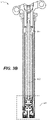
- FIG. 3B a cutaway view of the rotary flow control valve assembly 333 in the dropper seatpost assembly 300 of Figure 3A is shown in accordance with an embodiment.
- a discussion of the components that were visible and/or described in Figure 3A will not be repeated herein, but are incorporated by the discussion of Figure 3A in their entirety.
- dropper seatpost assembly 300 includes IFP (Internal Floating Piston) 381, translating shaft 402, and cutaway sectional view 391.
- IFP Internal Floating Piston
- the IFP 381 charge allows a gas spring to be used to extend the dropper seatpost assembly 300.
- the rotary flow control valve assembly 333 is shown at the bottom 326 of dropper seatpost assembly 300.
- the cross section is used to show one embodiment of the configuration of dropper seatpost assembly 300 including the location of IFP 381 and the rotary flow control valve assembly 333.
- one or more details of rotary flow control valve assembly 333 including different possible installation locations, variations, components, operational characteristics and the like are possible.
- the use of the embodiment of Figure 3B is provided as an example of one embodiment and used herein for purposes of clarity.
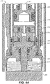
- rotary flow control valve assembly 333 includes a piston 405 connected to a translating shaft 402, a first chamber or inner chamber which is a fluid chamber pressurized by a rider's weight on the saddle 10.
- first chamber is referred to hereinafter as an inner fluid chamber 410 (or inner pressure tube).
- rotary flow control valve assembly 333 also includes a second chamber having an annular region about inner fluid chamber 410 which is pressurized on extension and by the IFP 381.
- the second chamber is referred to hereinafter as an outer fluid chamber 415 (or outer pressure tube).
- the actions of the two chambers are reversed, e.g., the inner fluid chamber 410 is pressurized on extension and by the IFP 381 and the outer fluid chamber 415 is pressurized by the rider's weight on the saddle 10.
- rotary flow control valve assembly 333 is an electronic rotary flow control valve assembly which includes a rotary flow control valve 420 with a drive feature 425 which is coupled to motor 450. In one embodiment, the rotational input from motor 450 into drive feature 425 will change the rotary position of rotary flow control valve 420.
- motor 450 is a brushed DC motor with a gearbox. In one embodiment, motor 450 is a stepper motor, brushless motor, coreless motor, or the like.
- the hard stop is used in the control system for the motor 450 as a current limit. For example, in one embodiment, when the motor 450 is activated, it will run until the motor 450 hits its current limit and is shut off. In so doing, the electronic rotary flow control valve assembly will quickly rotate the rotary flow control valve 420 the approximate 90 degree throw without requiring any additional controllers, inputs, etc.
- the cutout 422 in a portion of the rotary flow control valve 420 that interfaces with the lug 423 is used to key the rotary flow control valve 420 to the cross holes 503.
- rotary flow control valve assembly 333 is (effectively) a two-state valve.
- the rotary flow control valve assembly 333 is an on/off valve.
- the rotary flow control valve 33 is an on/off valve such that it is fast enough in its response such that a user would not be able to stop the dropper seatpost assembly 300 between states (e.g., state 1-the original user set saddle height and state-2 the lowest dropper seatpost setting).
- the rotary flow control valve assembly 333 may have intermediate states (to limit flow, such as a high flow, a medium flow, a slow flow, etc., but not at zero flow).
- the rotary flow control valve assembly 333 could have intermediate settings to control flow.
- there may be a control system (an encoder on motor 450 with different settings thereon, a stepper motor, etc.) to control/adjust the on/off type rotating valve into one or more intermediate states, (e.g., between on and off), to provide a regulated flow.
- translating shaft 402 moves up and down with the saddle 10.
- the translating shaft 402 is attached to the piston 405 to create the inner fluid chamber 410 which is at high pressure when the rider weight is being supported.
- the outer fluid chamber 415 is a fluid chamber that is annular to the inner fluid chamber 410.
- the rotary flow control valve 420 is opened, the fluid in the inner fluid chamber 410 moves through the open rotary flow control valve 420 and into the outer fluid chamber 415.
- the movement of the fluid into the outer fluid chamber 415 will move the IFP 381 upward toward the top of the dropper seatpost assembly 300 as the dropper seatpost assembly 300 is compressed (or moved into its lower height).
- FIG. 4B a cross-section view (identified in Figure 3B ) of a portion of the dropper seatpost assembly 300 including a mechanical actuator 481 (e.g., a cable, hydraulic line, etc.) for mechanically actuating rotary flow control valve assembly 333 is shown in accordance with an embodiment.
- a mechanical actuator 481 e.g., a cable, hydraulic line, etc.
- the operation of the embodiment shown in Figure 4B is similar to that of Figure 4A , except for the change from a motor 450 used to electronically drive the rotary flow control valve assembly 333 of Figure 4A , to a mechanical actuator to mechanically actuate the rotary flow control valve assembly 333.
- the mechanical actuator 481 would provide a control capability such that a user input on a user interface 205 (or similar type device) would provide a mechanical actuation of the rotary flow control valve within the rotary flow control valve assembly 333 to change the state from open, to closed, and/or to partially open.
- rotary flow control valve assembly 333 the components of rotary flow control valve assembly 333 are coupled together during manufacture/assembly to form a single rotary flow control valve assembly 333.
- rotary flow control valve assembly 333 is broken down into two or more distinct and/or different component assemblies which are connectively coupled during installation to form an operational rotary flow control valve assembly 333.
- one component assembly will include the piston 405, translating shaft 402, inner fluid chamber 410, outer fluid chamber 415, rotary flow control valve 420, and part of drive feature 425
- another component assembly will include part of a first assembly (e.g., may be located within the dropper seatpost assembly 300 and sealed from atmosphere while the drive feature 425 will extend through a seal of some type and out of the bottom 326 of dropper seatpost assembly 300) and the motor 450 is installed at a different location on the bicycle 50.
- the rotary flow control valve assembly 333 upon installation of the dropper seatpost assembly 300 into the seat tube 93, the rotary flow control valve assembly 333 will be operationally assembled when the drive feature 425 of the rotary flow control valve 420 is in mechanical contact with motor 450.
- this mechanical contact occur when the motor 450 is installed within the seat tube 93 and the drive feature 425 makes mechanical contact therewith. In another embodiment, this mechanical contact occurs when the motor 450 is installed somewhere else on the vehicle and a mechanical connection is made between the drive feature 425 and the motor 450. In one embodiment, the mechanical connection may be a cable or the like that is coupled between the motor 450 and the drive feature 425, thereby allowing the output of motor 450 to be rotationally transferred to drive feature 425.
- rotary flow control valve assembly 333 also includes a battery power source and a transmitter/receiver (described herein) to provide the input signal and power to motor 450 causing motor 450 to operate the rotary flow control valve 420.
- the battery power source is a disposable battery.
- the battery is a rechargeable battery.
- the battery can be recharged wired or wirelessly.
- the components of rotary flow control valve assembly 333 are installed together during the build of dropper seatpost assembly 300, such that the piston 405, translating shaft 402, inner fluid chamber 410, outer fluid chamber 415, rotary flow control valve 420, drive feature 425 and motor 450 are within the sealed atmospheric environment of the dropper seatpost assembly 300.
- this is referred to as a single rotary flow control valve assembly 333 housing embodiment.
- the single rotary flow control valve assembly 333 housing embodiment may include an O-ring or other type of seal about the drive feature 425 between the rotary flow control valve 420 and motor 450 to divide the single rotary flow control valve assembly 333 into a "wet" side and a “dry” side.
- the "wet" side components e.g., piston 405, translating shaft 402, inner fluid chamber 410, outer fluid chamber 415, rotary flow control valve 420
- the "dry" side components e.g., motor 450, transmitters, battery, noncontact charging components, and the like
- the seal would be located somewhere along the drive feature 425 such that the working fluid can use the flow paths, e.g., inner fluid chamber 410, outer fluid chamber 415, rotary flow control valve 420, cross holes 503 (of Figures 5B and 5E ), and the like, and flow can be controlled by the "wet” components, while the “dry” components will remain separate from the working fluid.
- the working fluid can use the flow paths, e.g., inner fluid chamber 410, outer fluid chamber 415, rotary flow control valve 420, cross holes 503 (of Figures 5B and 5E ), and the like, and flow can be controlled by the "wet” components, while the “dry” components will remain separate from the working fluid.
- the seal is also a pressure type fluid seal such that the "wet" components would be in a pressurized environment, while the “dry” components would remain at atmosphere.
- the battery for the rotary flow control valve assembly 333 could be accessible for battery replacement.
- some, or a portion of the bottom 326 could be removable to provide access to the battery and then be reinstalled to provide a level of protection from debris, water, etc. to the dropper seatpost assembly 300.
- a charging port for the battery of the single rotary flow control valve assembly 333 housing could be provided in the dropper seatpost assembly 300 wherever the single rotary flow control valve assembly 333 housing is located.
- bottom 326 could include a charging port.
- the charging port would include a dust cover (or the like) to provide a level of protection from debris, water, etc. to the dropper seat post assembly when it is not in use.
- the battery (or other power source such as a capacitor, etc.) has a wirelessly rechargeable capability such that the battery could be charged using a wireless power transfer system.
- a wireless power transfer system e.g., using an inductive charger (or the like) within a given distance of the wirelessly rechargeable capability of the battery.
- Wireless charging in its most basic form utilizes a copper coil to create an oscillating magnetic field, which can create a current in one or more receiver antennas.
- the wireless charger could be a charging pad that use tightly-coupled electromagnetic inductive or non-radiative charging;
- a charging bowl or through-surface type charger that uses loosely-coupled or radiative electromagnetic resonant charging to transmit a charge a few inches;
- An uncoupled radio frequency wireless charger that allows a trickle charging capability at distances of many feet, or the like.
- Examples of a wireless power transfer systems that could be used in one or more embodiments include those defined by the wireless power consortium (WPC) Qi standard, the AirFuel Alliance (e.g., Duracell Powermat, PowerKiss, etc.), WiTricity, and the like.
- WPC wireless power consortium
- AirFuel Alliance e.g., Duracell Powermat, PowerKiss, etc.
- WiTricity e.g., WiTricity, and the like.
- the battery can be charged even though it is sealed within the dropper seatpost assembly 300. In one embodiment, the battery can be charged while the dropper seatpost assembly 300 is installed in the seat tube 93. This can be dependent upon factors such as, the bicycle frame 119 (e.g., composite, metal, thin, thick, etc.), the type of wireless power transfer being used, etc.
- the dropper seatpost assembly 300 is removed from seat tube 93, and the portion of the dropper seatpost assembly 300 containing the rotary flow control valve assembly 333, including the battery, would be located proximate to the wireless charger to obtain the wireless charge.
- rotary flow control valve 420 includes at least one sealing portion 433 and one or more slots 431.
- at least one sealing portion 433 is aligned with the one or more cross holes 503 (shown in Figures 5B and 5D )
- fluid flow between inner fluid chamber 410 and outer fluid chamber 415 is stopped.
- one or more slots 431 are aligned with the one or more cross holes 503 (shown in Figures 5B and 5C )
- fluid flow between inner fluid chamber 410 and outer fluid chamber 415 can occur.
- the direction of the fluid flow is based on the pressure differential between the working fluid within the inner fluid chamber 410 and outer fluid chamber 415. For example, if the dropper seatpost assembly 300 is in its extended state and the rider is sitting on the saddle 10, there will be more pressure on the fluid in inner fluid chamber 410. As such, when rotary flow control valve 420 is opened, the working fluid will flow from inner fluid chamber 410 to outer fluid chamber 415.
- the rotary flow control valve 420 is a short throw valve where the difference between the open and the closed position is approximately 90 degrees or less.
- the dropper seatpost assembly 300 will begin moving prior to the rotary flow control valve 420 completing its throw.
- the exposed cross holes 503 have an angular sweep. As such, as soon as the rotary flow control valve 420 begins to expose the cross holes 503 between the inner fluid chamber 410 and the outer fluid chamber 415 fluid will start flowing and the dropper seatpost assembly 300 will start moving.
- the rotary flow control valve 420 is designed such that the angular rotation between the sealed state and the start of flow is minimized.
- the cross holes 503 instead of the cross holes 503 being circular, other shapes and combinations of shapes may be used between the body and the rotary flow control valve 420.
- a grid of holes instead of single cross holes 503, a grid of holes are used instead of single cross holes.
- a grid of holes, horizontal slot, other shapes or combinations of shapes are used instead of single cross holes to reduce the opportunity for seal extrusion.
- the rotary flow control valve 420 is a short throw valve where the difference between the open and the closed position is approximately 180 degrees or less.
- the rotary flow control valve 420 is a single rotation valve where the difference between the open and the closed position is approximately 360 degrees or less.
- Figure 5B is a partially cutaway view of the rotary flow control valve 420 of Figure 5A installed within the rotary flow control valve assembly 333 with cross holes 503 and is shown in accordance with an embodiment.
- Figure 5C is a cross-section view of the rotary flow control valve 420 installed within the rotary flow control valve assembly 333 with cross holes 503 of Figure 5B not shown in accordance with the position of rotary flow control valve 420 per an embodiment.
- the rotary flow control valve 420 has been rotated (as shown by rotational arrow 512) into an open position such that fluid may flow 510 between the inner fluid chamber 410 and the outer fluid chamber 415 (not shown in this Figure for clarity) via the one or more slots 431 in the rotary flow control valve and through cross holes 503.
- the fluid will flow 510 from the inner fluid chamber 410 through the one or more slots 431 in rotary flow control valve 420 and cross holes 503 and into the outer fluid chamber 415.
- the fluid will flow 510 from the outer fluid chamber 415 through the cross holes 503 and the one or more slots 431 in rotary flow control valve 420 and into the inner fluid chamber 410.
- Figure 5D is a partially cut-away view of the rotary flow control valve 420 of Figure 5A installed within the rotary flow control valve assembly 333 in a closed position (e.g., blocking cross holes 503) shown in accordance with an embodiment.
- Figure 5E is a cross-section view of the rotary flow control valve 420 installed within the rotary flow control valve assembly 333 in a closed position (e.g., the sealing portion 433 blocking fluid flow through cross holes 503) shown in accordance with an embodiment.
- the rotary flow control valve assembly 333 includes the rotary flow control valve 420 and a rotary motor 450, such that all of the motion is rotary and as such, there is no need for any rotary to linear conversion. In other words, in one embodiment, there is no rotary to linear transmission and therefore no rotary to linear transmission is required. E.g., there is no need to convert the rotating motion from a motor to linear actuation motion.
- the output shaft from motor 450 is used as the drive feature 425 for rotary flow control valve 420.
- the rotary flow control valve 420 has bi-directional sealing. In other words, the rotary flow control valve 420 will fluidly seal the inner fluid chamber 410 from fluid communication with the outer fluid chamber 415 when the dropper seatpost assembly 300 is in the extended state to support compressive forces, e.g., the rider's interactions with the saddle 10 while riding. In so doing, the rider can ride the bike without the dropper seatpost assembly 300 lowering down before rotary flow control valve assembly 333 receives a commanded to do so.
- the rotary flow control valve 420 will also fluidly seal the inner fluid chamber 410 from fluid communication with the outer fluid chamber 415 when the dropper seatpost assembly 300 is in the lowered state to support extension forces, e.g., the saddle 10 will remain in the lowered position even when upward forces are applied to the saddle 10. In so doing, the rider can use the saddle 10 (and or dropper seatpost assembly 300) to lift up some or all of the bike without the dropper seatpost assembly 300 moving upward.
- dropper seatpost assembly 300 will remain in the lowered state until rotary flow control valve assembly 333 receives a commanded to rotate the rotary flow control valve 420 into an open (or partially open) valve position thereby allowing the dropper seatpost assembly 300 to extend.
- Figure 6A is a perspective view of the head of rotary flow control valve 420 with one or more O-ring type seals 625 installed in a gland in accordance with an embodiment.
- Figure 6B is a top view of the head of rotary flow control valve 420 with one or more O-ring type seals 625 installed in glands thereon in accordance with an embodiment.
- FIG 7A is a perspective cross-section view of the rotary flow control valve 420 with one or more preload pads 720 installed thereon in accordance with an embodiment.
- each of the preload pads 720 consists of sealing material (e.g., a Teflon pad or the like) and a compliant material 725 is used to establish the preload on the sealing material of preload pads 720.
- Figure 7B is a perspective view of the rotary flow control valve 420 with one or more preload pads 720 installed thereon in accordance with an embodiment.
- Figure 7C is a side view of the rotary flow control valve 420 with one or more preload pads 720 installed thereon in accordance with an embodiment.
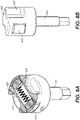
- Figure 8A is a top perspective cross-section view of the rotary flow control valve 420 with one or more preload pads 820 installed thereon in accordance with an embodiment.
- each of the preload pads 820 consists of sealing material (e.g., a Teflon pad or the like) and a spring 825 is used to establish the preload on the preload pads 820.
- Figure 8B is a perspective view of the rotary flow control valve 420 of Figure 8A with one or more preload pads 820 installed thereon in accordance with an embodiment.
- Figure 9A is a perspective view of a rotary flow control valve 420 with an optional flow hole 905 therethrough, in accordance with an embodiment.
- rotary flow control valve 420 of Figure 9A is a self-charging seal design that includes an optional through hole (or flow hole 905) through a portion of rotary flow control valve 420, one or more slots 431, a drive feature 425, and at least one sealing portion 433.
- the optional flow hole 905 acts like a "charging port" to provide additional fluid pressure to sealing portion 433 to retain a zero fluid flow rate between inner fluid chamber 410 and outer fluid chamber 415.
- the flow hole 905 is optional depending upon the operating pressures on the fluids in one or both of inner fluid chamber 410 and/or outer fluid chamber 415.
- the at least one sealing portion 433 includes a first seal portion 901 and a second seal portion 902.
- first seal portion 901 seals to an inner diameter of the cross holes 503 in the wall separating the inner fluid chamber 410 from the outer fluid chamber 415.
- second seal portion 902 provides an additional seal surface area that is provided against the area of the wall surrounding the cross holes 503, and is used to increase the area of the at least one sealing portion 433 that is exposed to the fluid pressure differential (as shown in Figures 9B-9D ).
- the size of second seal portion 902 is tailored to the specific application in which the rotary flow control valve 420 and/or the rotary flow control valve assembly 333 is being used. For example, if the sealing area of sealing portion 433 was equivalent only to the first seal portion 901 (e.g., the bore or flow hole 905 diameter), the high pressure would act over the entire area and the friction would be high. However, by using the increased size of sealing portion 433 to include the second seal portion 902, the area on both sides of the area that the high pressure is acting on are balanced, thereby limiting the normal force between the sealing portion 433 and the flow hole 905.
- Figure 9B is a cross-section view of the rotary flow control valve 420 with a flow hole 905 therethrough installed within the rotary flow control valve assembly 333, in accordance with an embodiment.
- rotary flow control valve 420 of Figure 9B is a self-charging seal design that includes a through hole (or flow hole 905) through a portion of rotary flow control valve 420 and one or more plungers 920.
- Figure 9C is a top perspective cross-section view of a rotary flow control valve 420 with a flow hole 905 therethrough installed within the rotary flow control valve assembly 333, in accordance with an embodiment.
- Figure 9D is a cross-section view of the rotary flow control valve 420 with a flow hole 905 therethrough installed within the rotary flow control valve assembly 333, in accordance with an embodiment.
- rotary flow control valve 420 of Figures 9C and 9D is a self-charging seal design that includes a through hole (or flow hole 905) through a portion of rotary flow control valve 420 and one or more plungers 920.
- the high pressure is provided from the outer fluid chamber 415 and passes using a flow path indicated by arrows 935 along a portion of one or more plungers 920.
- This high pressure feeds into the one or more O-rings 934 which increases a force applied from the one or more plungers 920 to the one or more sealing portions 433.
- This increase in force increases the sealing force of one or more plungers 920 which keeps fluid from flowing from outer fluid chamber 415 through the flow hole 905 and into inner fluid chamber 410.
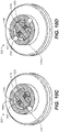
- Figure 10A is a cross-section view of the rotary flow control valve 420 with a single O-ring installed within the rotary flow control valve assembly 333, in accordance with an embodiment.
- rotary flow control valve assembly 333 includes the rotary flow control valve 420 with drive feature 425, inner fluid chamber 410, at least one O-ring 1020, a rod 1010, and one or more seals 1033.
- rod 1010 is used to support the at least one O-ring 1020 so that it does not collapse under any high pressures from the working fluid.
- the at least one O-ring 1020 charges the one or more seals 1033 and there is some area between the one or more seals 1033 and the rotary flow control valve 420 that is charged by the high pressure fluid in inner fluid chamber 410 causing the one or more seals 1033 to move outward toward cross holes 503.
- Figure 10B is a perspective view of the rotary flow control valve 420 with a single O-ring configuration of Figure 10A.
- Figure 10B shows the rotary flow control valve 420, the one or more seals 1033, and the rod 1010.
- Figure 10C is a top perspective cut away view of the rotary flow control valve 420 with a single O-ring configuration installed within the rotary flow control valve assembly 333 in a closed state, in accordance with an embodiment.
- rod 1010 is used to support the at least one O-ring 1020 so that it does not collapse under any high pressures from the working fluid.
- the at least one O-ring 1020 charges the one or more seals 1033 and there is some area between the one or more seals 1033 and the rotary flow control valve 420 that is charged by the high pressure fluid in inner fluid chamber 410 causing the one or more seals 1033 to move outward toward cross holes 503 thereby closing the fluid path through cross holes 503.
- Figure 10D is a top perspective cut away view of the rotary flow control valve 420 with a single O-ring configuration installed within the rotary flow control valve assembly 333 in an open state, in accordance with an embodiment.
- rod 1010 In the open state, rod 1010 continues to support the at least one O-ring 1020 so that it does not collapse under any high pressures from the working fluid.
- the at least one O-ring 1020 charges the one or more seals 1033 and there is some area between the one or more seals 1033 and the rotary flow control valve 420 that is charged by the high pressure fluid in inner fluid chamber 410 causing the one or more seals 1033 to move outward.
- the rotary flow control valve 420 is now rotated such that the one or more seals 1033 are moving toward the wall 1065 between the inner fluid chamber 410 and the outer fluid chamber 415 and not toward cross holes 503 in wall 1065, the one or more slots 431 in rotary flow control valve 420 are providing an open fluid path between outer fluid chamber 415 and inner fluid chamber 410. In so doing, the fluid can flow from the higher pressure differential to the lower pressure differential between inner fluid chamber 410 and outer fluid chamber 415 through one or more slots 431 and cross holes 503.
- Figure 11A is a cross-section view of a portion of a rotary flow control valve assembly 333 with a rotating shaft configuration, in accordance with an embodiment.
- the reason for using a rotating shaft style versus a rotating seal style is that in the rotating seal style the friction interface (e.g., between the sealing portion 433 and the wall 1065 between inner fluid chamber 410 and outer fluid chamber 415) is as far away from the centerline as possible (e.g., on the outside perimeter of rotary flow control valve 420). This distance from centerline is the longest possible moment arm and as such would maximize the torque required to rotate the rotary flow control valve 420.
- the friction interface is moved closer to the center line thereby reducing the length of the moment arm and thus the torque required to rotate the rotating shaft as compared to the torque required to rotate the rotary flow control valve 420 in the rotating seal configuration.
- the housing of the rotary flow control valve 420 does not rotate. Instead, the shaft within the rotary flow control valve 420 will rotate within the housing.
- rotary flow control valve assembly 333 includes a rotary flow control valve 420 housing 1104, one or more cross holes 503, at least one O-ring 1120, a stub shaft 1110, at least one sealing portion 1133, a rotating drive shaft 425 (in the form of a ball valve, or other geometric shape), flow holes 905, a motor output shaft 1144, and a flow path 1118 shown in the flow holes 905 between the inner fluid chamber 410 and outer fluid chamber 415; where the inner fluid chamber 410 would be found above the opening at the top of the rotating drive shaft 425 and the outer fluid chamber 415 would be to the exterior of the one or more cross holes 503.
- the rotary flow control valve 420 housing 1104 does not rotate. Instead, the drive shaft 425 is the portion that rotates.
- the at least one sealing portion 1133 e.g., ball valve seats
- the at least one sealing portion 1133 is a dynamic seal in the sense that there is motion between the rotating drive shaft 425 and the at least one sealing portion 1133.
- the at least one O-ring 1120 seals to the one or more cross holes 503 and the inner fluid chamber 410 and charge the ball valve seat (e.g., the at least one sealing portion 1133) to create the pressure for the at least one sealing portion 1133.
- the stub shaft 1110 is used to keep the at least one O-ring 1120 from compressing on itself under pressure.
- the motor output shaft 1144 is coupled with the drive shaft 425.
- the motor output shaft 1144 and the drive shaft 425 may be a single piece.
- drive shaft 425 includes a ball valve type of shape and has a flow hole 905 therethrough.
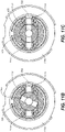
- FIG. 11B a top cross-section view of the rotary flow control valve assembly 333 with a rotating drive shaft in a closed state configuration is shown in accordance with an embodiment.
- housing 1104 does not rotate
- stub shaft 1110 is used to support the at least one O-ring 1120 so that it does not collapse under any high pressures from the working fluid.
- the at least one O-ring 1120 charges the at least one sealing portion 1133, and the rotating drive shaft 425 with flow hole 905 is rotated to a closed position where the flow hole 905 is not aligned with cross holes 503 thereby stopping the fluid from using the fluid path of flow hole 905 from moving between inner fluid chamber 410 and outer fluid chamber 415 (as shown in Figures 4A and 4B ).
- Figure 11C is a top cross-section view of the rotary flow control valve assembly 333 with a rotating drive shaft in an open state configuration, in accordance with an embodiment.
- housing 1104 still does not rotate, stub shaft continues to support the at least one O-ring 1020 so that it does not collapse under any high pressures from the working fluid.
- the at least one O-ring 1020 charges the at least one sealing portion 1133 and the rotating drive shaft 425 with flow hole 905 is rotated to an open position.
- the flow hole 905 within rotating drive shaft 425 provides an open fluid flow path between outer fluid chamber 415 and inner fluid chamber 410. In so doing, the fluid can flow from the higher pressure differential to the lower pressure differential between inner fluid chamber 410 and outer fluid chamber 415 through the flow hole 905 and cross holes 503.
- Figure 11D is a cross-section view of a portion of a rotary flow control valve assembly 333 with a rotating shaft configuration having a one piece ball valve seat, in accordance with an embodiment.
- the components and operation of Figure 11D are similar to those of Figure 11A . As such, the discussion of Figure 11D will only include the differences between Figure 11D and Figure 11A .
- the at least one sealing portion 1133 is combined with stub shaft 1110 in a single piece ball valve seat 1180.
- rotary flow control valve assembly 333 includes a rotary flow control valve 420 housing 1104, at least one O-ring 1120, a stub shaft 1110, at least one sealing portion 1133, a rotating drive shaft 425 (in the form of a cylindrical shaft, or other geometric shape), flow holes 905, and a flow path 1118 shown in the flow holes 905 between the inner fluid chamber 410 and outer fluid chamber 415; where the inner fluid chamber 410 would be found above the opening at the top of the rotating drive shaft 425 and the outer fluid chamber 415 would be to the exterior of the stub shaft 1110.
- the rotary flow control valve 420 housing 1104 does not rotate. Instead, the drive shaft 425 is the portion that rotates.
- the at least one sealing portion 1133 e.g., valve seats
- the at least one sealing portion 1133 is a dynamic seal in the sense that there is motion between the rotating drive shaft 425 and the at least one sealing portion 1133.
- the at least one O-ring 1120 seals to the one or more cross holes and the inner fluid chamber 410 and charge the valve seat (e.g., the at least one sealing portion 1133) to create the pressure for the at least one sealing portion 1133.
- the stub shaft 1110 is used to keep the at least one O-ring 1120 from compressing on itself under pressure.
- the motor output shaft is coupled with the drive shaft 425.
- the motor output shaft and the drive shaft 425 may be a single piece.
- drive shaft 425 includes a cylindrical shape and has a flow hole 905 therethrough.
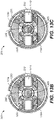
- FIG. 12B a top cross-section view of the rotary flow control valve assembly 333 with a rotating drive shaft 425 having a cylindrical shape is shown in a closed state configuration in accordance with an embodiment.
- housing 1104 does not rotate
- stub shaft 1110 is used to support the at least one O-ring 1120 so that it does not collapse under any high pressures from the working fluid.
- the at least one O-ring 1120 charges the at least one sealing portion 1133, and the rotating drive shaft 425 with flow hole 905 is rotated to a closed position where the flow hole 905 is not aligned with cross holes 503 thereby stopping the fluid from using the fluid path of flow hole 905 from moving between inner fluid chamber 410 and outer fluid chamber 415 (as shown in Figures 4A and 4B ).
- Figure 12C is a top cross-section view of the rotary flow control valve assembly 333 with a rotating drive shaft having a cylindrical shape is shown in an open state configuration in accordance with an embodiment.
- housing 1104 still does not rotate, stub shaft continues to support the at least one O-ring 1020 so that it does not collapse under any high pressures from the working fluid.
- the at least one O-ring 1020 charges the at least one sealing portion 1133 and the rotating drive shaft 425 with flow hole 905 is rotated to an open position.
- the flow hole 905 within rotating drive shaft 425 provides an open fluid flow path between outer fluid chamber 415 and inner fluid chamber 410. In so doing, the fluid can flow from the higher pressure differential to the lower pressure differential between inner fluid chamber 410 and outer fluid chamber 415 through the flow hole 905 and cross holes 503.
- rotary flow control valve assembly 333 is similar to the rotary flow control valve assembly 333 of Figure 12A , and includes a rotary flow control valve 420 housing 1104, at least one dynamic O-ring 1120, at least one static O-ring 1220, and at least one component 1233, a stub shaft 1110, a rotating drive shaft 425 (in the form of a cylindrical shaft, or other geometric shape), flow holes 905, and a flow path 1118 shown in the flow holes 905 between the inner fluid chamber 410 and outer fluid chamber 415; where the inner fluid chamber 410 would be found above the opening at the top of the rotating drive shaft 425 and the outer fluid chamber 415 would be to the exterior of the stub shaft 1110.
- the rotary flow control valve 420 housing 1104 does not rotate. Instead, the drive shaft 425 is the portion that rotates.
- the at least one static O-ring 1220 seals to the inner diameter (ID) of the inner fluid chamber 410 and loads through the at least one component 1233 which loads the at least one dynamic O-ring 1120 which creates the dynamic seal between the rotating drive shaft 425 and the seal.
- the stub shaft 1110 is used to keep the at least one O-ring 1120 and 1220 from compressing on themselves under pressure.
- the motor output shaft is coupled with the drive shaft 425.
- the motor output shaft and the drive shaft 425 may be a single piece.
- drive shaft 425 includes a cylindrical shape and has a flow hole 905 therethrough.
- FIG. 13B a top cross-section view of the dual O-ring rotary flow control valve assembly 333 with a rotating drive shaft 425 having a cylindrical shape is shown in a closed state configuration in accordance with an embodiment.
- housing 1104 does not rotate, stub shaft 1110 is used to support the at least one O-ring 1120 and 1220 so that they do not collapse under any high pressures from the working fluid.
- the at least one static O-ring 1220 seals to the ID of the inner fluid chamber 410 and loads through the at least one component 1233 which loads the at least one dynamic O-ring 1120 which creates the dynamic seal between the rotating drive shaft 425 and the seal, and the rotating drive shaft 425 with flow hole 905 is rotated to a closed position where the flow hole 905 is not aligned with cross holes 503 thereby stopping the fluid from using the fluid path of flow hole 905 from moving between inner fluid chamber 410 and outer fluid chamber 415 (as shown in Figures 4A and 4B ).
- Figure 13C is a top cross-section view of the dual O-ring rotary flow control valve assembly 333 with a rotating drive shaft having a cylindrical shape is shown in an open state configuration in accordance with an embodiment.
- housing 1104 still does not rotate, stub shaft continues to support the at least one O-ring 1120 and 1220 so that they do not collapse under any high pressures from the working fluid.
- the at least one static O-ring 1220 seals to the ID of the inner fluid chamber 410 and loads through the at least one component 1233 which loads the at least one dynamic O-ring 1120 which creates the dynamic seal between the rotating drive shaft 425 and the seal, and the rotating drive shaft 425 with flow hole 905 is rotated to an open position.
- the flow hole 905 within rotating drive shaft 425 provides an open fluid flow path between outer fluid chamber 415 and inner fluid chamber 410. In so doing, the fluid can flow from the higher pressure differential to the lower pressure differential between inner fluid chamber 410 and outer fluid chamber 415 through the flow hole 905 and cross holes 503.
- Figure 14A is a perspective view of a rotating drive shaft 425 in the form of a cylindrical shaft configuration with one or more slots 1431 therein.
- the rotating drive shaft 425 utilizes one or more slots 1431.
- FIG. 14B a cross-section view of a portion of a dual O-ring rotary flow control valve assembly 333 having a rotating drive shaft 425 in the form of a cylindrical shaft configuration with one or more slots 1431 is shown in accordance with an embodiment.
- rotary flow control valve assembly 333 is similar to the rotary flow control valve assembly 333 of Figure 13A , and includes a rotary flow control valve 420 housing 1104, at least one dynamic O-ring 1120, at least one static O-ring 1220, and at least one component 1233, a stub shaft 1110, a rotating drive shaft 425 (in the form of a cylindrical shaft, or other geometric shape), one or more slots 1431, and a flow path 1118 shown along one or more slots 1431 between the inner fluid chamber 410 and outer fluid chamber 415; where the inner fluid chamber 410 would be found above the opening at the top of the rotating drive shaft 425 and the outer fluid chamber 415 would be to the exterior of the stub shaft 1110.
- the rotary flow control valve 420 housing 1104 does not rotate. Instead, the drive shaft 425 is the portion that rotates.
- the at least one static O-ring 1220 seals to the inner diameter (ID) of the inner fluid chamber 410 and loads through the at least one component 1233 which loads the at least one dynamic O-ring 1120 which creates the dynamic seal between the rotating drive shaft 425 and the seal.
- the stub shaft 1110 is used to keep the at least one O-ring 1120 and 1220 from compressing on themselves under pressure.
- the motor output shaft is coupled with the drive shaft 425.
- the motor output shaft and the drive shaft 425 may be a single piece.
- drive shaft 425 includes a cylindrical shape and has one or more slots 1431 therethrough.
- FIG. 14C a top cross-section perspective view of the dual O-ring rotary flow control valve assembly 333 with a rotating drive shaft 425 having a cylindrical shape and one or more slots 1431 therein is shown in a closed state configuration in accordance with an embodiment.
- housing 1104 does not rotate, stub shaft 1110 is used to support the at least one O-ring 1120 and 1220 so that they do not collapse under any high pressures from the working fluid.
- the at least one static O-ring 1220 seals to the ID of the inner fluid chamber 410 and loads through the at least one component 1233 which loads the at least one dynamic O-ring 1120 which creates the dynamic seal between the rotating drive shaft 425 and the seal, and the rotating drive shaft 425 with one or more slots 1431 is rotated to a closed position such that the one or more slots 1431 are not aligned with cross holes 503 thereby stopping the fluid from using the fluid path of flow hole 905 from moving between inner fluid chamber 410 and outer fluid chamber 415 (as shown in Figures 4A and 4B ).
- Figure 14D is a top cross-section view of the dual O-ring rotary flow control valve assembly 333 with a rotating drive shaft having a cylindrical shape and one or more slots 1431 is shown in an open state configuration in accordance with an embodiment.
- housing 1104 still does not rotate, and stub shaft continues to support the at least one O-ring 1120 and 1220 so that they do not collapse under any high pressures from the working fluid.
- the at least one static O-ring 1220 seals to the ID of the inner fluid chamber 410 and loads through the at least one component 1233 which loads the at least one dynamic O-ring 1120 which creates the dynamic seal between the rotating drive shaft 425 and the seal, and the rotating drive shaft 425 with one or more slots 1431 is rotated to an open position.
- the one or more slots 1431 of rotating drive shaft 425 provide an open fluid flow path between outer fluid chamber 415 and inner fluid chamber 410. In so doing, the fluid can flow from the higher pressure differential to the lower pressure differential between inner fluid chamber 410 and outer fluid chamber 415 through the one or more slots 1431 and cross holes 503.
- the network implements the proprietary low-latency low-power radio protocol to provide an effective transport for communication between rotary flow control valve assembly 333 and user interface 205.
- a unique ID is used during the programming/pairing of the rotary flow control valve assembly 333 with the user interface 205.
- the unique ID is used by rotary flow control valve assembly 333 to identify a valid user interface 205.
- any transmitted signal includes a unique identifier (ID) that identifies the user interface 205 that broadcast the signal.
- ID unique identifier
- the unique ID, and other data is stored in an erasable programmable read-only memory on a version of rotary flow control valve assembly 333.
- the memory can be written to with RF energy, NFC protocols, or the like. As such, the memory could be updated via user interface 205, a mobile device, a laptop, or the like.
- the wireless signal is a "telegram" or the like that includes the unique identifier (ID) that identifies the rotary flow control valve assembly 333 and/or the user interface 205 that broadcast the telegram signal.
- ID unique identifier
- the telegram signal will identify which device sent the signal.
- the unique ID is used in one embodiment, in another embodiment, a different portion of the telegram signal is used to identify the transmitting device.
- the telegram signal is sent via a radio frequency (RF) transmitter such as used in a wireless personal area network (WPAN), a low power network (LPN), Internet of things (IoT) connectivity, or the like.
- RF radio frequency
- the RF protocol could be, but is not limited to, Bluetooth, WiFi, Bluetooth Low Energy (BLE), near field communication (NFC), UHF radio signal, Worldwide Interoperability for Microwave Access (WiMax), industrial, scientific, and medical (ISM) band, IEEE 802.15.4 standard communicators, Zigbee, ANT, ISA100.11a (wireless systems for industrial automation: process control and related applications) wireless highway addressable remote transducer protocol (HART), MiWi, IPv6 over low-power wireless personal area networks (6LoWPAN), thread network protocol, subnetwork access protocol (SNAP), and the like.
- HART wireless highway addressable remote transducer protocol
- MiWi IPv6 over low-power wireless personal area networks
- 6LoWPAN subnetwork access
- the rotary flow control valve assembly 333 and/or the user interface 205 transmitter is powered by a momentary generator such as ZF electronics AFIG-0007 or the like.
- a momentary generator such as ZF electronics AFIG-0007 or the like.
- the rotary flow control valve assembly 333 and/or the user interface 205 will include an IEEE 802.2 logical link control sublayer to receive and interpret the signal.
- the communication capabilities of the rotary flow control valve assembly 333 and/or user interface 205 resemble a system such as the ZF Electronics AFIS-5003 with a SNAP transmitter, and the receiving device will have a universal asynchronous receiver/transmitter (UART) interface supporting RS-232 or RS-485 using TTL logic levels to receive and interpret the signal.
- UART universal asynchronous receiver/transmitter
- the rotary flow control valve assembly 333 and/or the user interface 205 will periodically send a heartbeat (e.g., check-in message), to inform the other of the rotary flow control valve assembly 333 and/or the user interface 205 that they are still active.
- a heartbeat e.g., check-in message
- the heartbeat is sent at a 1Hz communication rate.
- the other of the rotary flow control valve assembly 333 and/or the user interface 205 that did not send the heartbeat will provide a response message to confirm that there is a wireless connection therebetween.
- a timer is used by the rotary flow control valve assembly 333 and/or the user interface 205 to count down a check-in or heartbeat time period.
- the time period measured by the timer is preset by the manufacturer.
- the time period measured by the timer is adjustably set by the manufacturer, by the user, by a mechanic, based on the vehicle location, terrain type, or the like.
- the heartbeat is sent.
- the timer will be restarted.
- a microprocessor on the rotary flow control valve assembly 333 and/or the user interface 205 has a built-in radio capable of standard Bluetooth Low Energy and other communication as part of the ISM Band technologies.
- the rotary flow control valve assembly 333 and/or the user interface 205 uses Enhanced Shockburst (ESB).
- EBS Enhanced Shockburst
- the microprocessor on the rotary flow control valve assembly 333 and/or the user interface 205 build in radio protocol could be, but is not limited to, WiFi, NFC, UHF radio signal, WiMax, ISM band, an IEEE 802.15.4 standard communicator, Zigbee, ANT, ISA100.11a, wireless HART protocol, MiWi, IPv6, 6LoWPAN, thread network protocol, SNAP, and the like.
- user interface 205 has two wireless radios, e.g., radio 1 and radio 2.
- radio 1 handles wireless communication with peripherals where latency and/or battery life is not a concern.
- radio 1 could communicate with devices such as other controllers, sensors, mobile devices, a power meter, or the like where ⁇ 200 msec latency is not a problem.
- radio 2 handles the ESB communication and is dedicated to any low latency/low power devices such as rotary flow control valve assembly 333.
- having two operational radios is not that good from a battery life standpoint, but, in one embodiment, the user interface 205 houses a relatively large rechargeable battery. Thus, the expectation for the user interface 205 battery burn time is hours not months.
- rotary flow control valve assembly 333 has a single wireless radio that uses ESB communication and is always listening for a message from the user interface 205.
- the amount of power draw from the "always-listening" ESB radio is minimal.
- the always-listening is key for low latency communication.
- the user interface 205 when the user interface 205 has a message to send to rotary flow control valve assembly 333, it can be nearly instantaneously received by rotary flow control valve assembly 333 (or within 2 msec). In one embodiment, it can be received so quickly because the rotary flow control valve assembly 333 does not have to wake up and try to bond with the user interface 205 (a strategy normally employed to conserve battery life). It is already awake and ready.
- the initial operation of the wireless communication protocol is to pair the rotary flow control valve assembly 333 to the user interface 205.
- the wireless communication pairing is made resistant against attempts made by unauthorized actors trying to attack and control the system by performing authentication and encryption between the wireless components.
- system attacks include, but are not limited to, replay attacks, impersonation, denial of service, and the like.
- replay attacks refers to actions such as, but not limited to, an attacker recording one or more of the messages and playing them back to the device which mistakenly interprets them as valid messages from the sensor(s).
- impersonation refers to actions such as, but not limited to, an attacker pretending to be a sensor, and sending one or more messages directly to the rotary flow control valve assembly 333 and/or the user interface 205.
- denial of service refers to actions such as, but not limited to, an attacker sending one or more specially crafted messages that stop the system from working.
- denial of service refers to actions such as, but not limited to, an attacker sending one or more specially crafted messages that stop the system from working.
- the authentication and encryption between the rotary flow control valve assembly 333 and/or the user interface 205 includes the utilization of AES 128, or the like.
- the pairing procedure sets up all state required for the radio protocol to be secure, including the AES-128 symmetric key. Whenever a device - the rotary flow control valve assembly 333 and/or the user interface 205 - is turned on, it generates a session-specific 4-byte nonce using a secure random number generator. This nonce is included in all communication between devices.
- each device also stores a 4-byte sequence number, that starts at 0, and increments for every transmitted message.
- the AES-128 block cipher is operated in the Authenticated Encryption with Associated Data (AEAD) scheme, which allows encrypting the given plaintext, and authenticating associated plain text data.
- the AEAD scheme requires a 13-byte nonce value, referred to herein as AEADNonce. When the AES-128 symmetric key, and AEADNonce are unique for every packet, the connection is secured.
- the AEADNonce is constructed by concatenating the nonce of each device with the sequence number of the particular packet, for a total of 12 bytes, with the 13th byte padded with 00. This ensures the AEADNonce is unique, and the connection is therefore secure.
- the application does not accept any packet which it receives that has a sequence number earlier than another packet it has already received. This ensures that replay attacks are not possible. To generate new packets with a valid sequence number, the attacker must know the AES-128 symmetric key.
- Bluetooth communication (or the like) is used.
- ESB type communications is used.
- any further communications are made via ESB for the fast-communication state.
- the ESB protocol or similar ISM Band Technology
- the rotary flow control valve assembly 333 and/or the user interface 205 periodically send a heartbeat message (e.g., a check-in) to the other of the rotary flow control valve assembly 333 and/or the user interface 205 to make sure the system is working properly.
- a heartbeat message e.g., a check-in
- the rotary flow control valve assembly 333 since the rotary flow control valve assembly 333 is always listening for a message from the user interface 205, the rotary flow control valve assembly 333 will receive the message at the speed of the message being sent. In one embodiment, rotary flow control valve assembly 333 will send an acknowledgement message back to the user interface 205. In one embodiment, rotary flow control valve assembly 333 will not send an acknowledgement message back to the user interface 205.
- the communication latency is approximately 2.2 milliseconds.
- the Accelerometer i2C at 100 kHz is approximately 1000 microseconds
- the encryption is approximately 610 microseconds
- the time from the initiation of the transmission from user interface 205 until usable data is received at rotary flow control valve assembly 333 is approximately 545 microseconds.
- a message resend is then initiated.
- Each message resend attempt adds an average of 0.5 milliseconds latency. For example, if user interface 205 does not receive an acknowledgement message from the rotary flow control valve assembly 333 within a given amount of time, the user interface 205 sends the message again. For example, assume a 10% chance of message failure. In this case, there is a 10% chance of needing a second message attempt, a 1% chance of needing a 3rd message attempt, and a .1% chance of needing a 4th message attempt. Each message attempt adds about 0.5 milliseconds latency, so even a 4th message attempt will be within the "non-user perceptible" latency period.
- one or both of the rotary flow control valve assembly 333 and/or the user interface 205 can be in a number of different energy states to conserve battery life. Although a number of states are discussed, in one embodiment there may be more, fewer, or a different combination or variation of the described energy states. The use of the disclosed energy states is provided herein as one embodiment and for purposes of clarity.
- One state is referred to as the operating state. This is the highest battery power consumption state.
- the rotary flow control valve assembly 333 and/or the user interface 205 is transmitting and/or receiving data.
- a standby state the rotary flow control valve assembly 333 and/or the user interface 205 are awake and there is a connection therebetween.
- the user interface 205 is waiting to receive input from the user.
- user interface 205 will move into the operating state and transmit the data to rotary flow control valve assembly 333.
- rotary flow control valve assembly 333 when rotary flow control valve assembly 333 responds to the transmission from user interface 205, it will be known to both devices that there is a connection therebetween, that the signal has been received by rotary flow control valve assembly 333, and that one or both the rotary flow control valve assembly 333 and/or the user interface 205 can return to the standby state until the next time the user provides an input to user interface 205.
- the rotary flow control valve assembly 333 may not provide a response to the transmission from user interface 205. In one embodiment, user interface 205 may not expect a response from rotary flow control valve assembly 333 after user interface 205 sends the transmission.
- the rotary flow control valve assembly 333 may only provide the heartbeat message to the user interface 205 at pre-defined intervals to evidence the connection between user interface 205 and rotary flow control valve assembly 333.
- user interface 205 if user interface 205 expected but did not receive a response from rotary flow control valve assembly 333, user interface 205 will include a programmed pre-defined number of attempts at transmitting the signal to rotary flow control valve assembly 333 before making the determination that there is a disconnection in the communication between the user interface 205 and the rotary flow control valve assembly 333.
- the pre-defined number of attempts is based on the transmission rate. For example, in one embodiment, it is assumed that it takes 0.5 milliseconds of time for the user interface 205 to transmit a signal to rotary flow control valve assembly 333, for rotary flow control valve assembly 333 to transmit a message received transmission to user interface 205 and also cause motor 450 to rotate rotary flow control valve 420 to an open position thereby activating the dropper seatpost assembly 300.
- the pre-defined number of attempts taken by user interface 205 would be 3.
- user interface 205 will have tried as many times as possible (e.g., 0.5 x 3) to send the signal before the lack of dropper seatpost assembly 300 movement was noticed by the rider.
- the number of times the user interface 205 tries could be more or less.
- the use of three attempts is used herein in one embodiment.
- the user interface 205 determines that the bike is not being ridden (e.g., based on a user input, a sensor input, or the like) the user interface 205 will send a standby message to inform rotary flow control valve assembly 333 that the bike is not being ridden.
- the rotary flow control valve assembly 333 will transition to a low-power mode or sleep mode when the standby message is received.
- rotary flow control valve assembly 333 determines user interface 205 is turned off (or otherwise not responding)
- rotary flow control valve assembly 333 will enter a no-heartbeat standby state (e.g., an intermediate battery power consumption state), where rotary flow control valve assembly 333 is awake and listening but is not sending any transmissions (e.g., heartbeat transmissions, etc.).
- a no-heartbeat standby state e.g., an intermediate battery power consumption state
- rotary flow control valve assembly 333 will remain in the no-heartbeat standby state until the connection with user interface 205 is re-established. In one embodiment, when rotary flow control valve assembly 333 receives a message from user interface 205, it will know that the connection with user interface 205 is established (or re-established) and rotary flow control valve assembly 333 will transition from the no-heartbeat standby state to a heartbeat standby state.
- dormant state the bike is stationary. For instance, the bike is in storage or otherwise parked and not being ridden.
- one or both of the rotary flow control valve assembly 333 and/or the user interface 205 will go into low-power mode.
- rotary flow control valve assembly 333 while in the dormant state, rotary flow control valve assembly 333 will periodically wake up to transmit a signal to user interface 205. If no response is received, rotary flow control valve assembly 333 will return to the dormant state, e.g., go back to sleep.
- rotary flow control valve assembly 333 will change from the dormant state into the standby state.
- the rotary flow control valve assembly 333 and/or the user interface 205 can move between the different states fluidly using the model described above. In one embodiment, the rotary flow control valve assembly 333 and/or the user interface 205 will try to remain in (or return to) the lowest powered state for the specific situation.
- the estimate of battery life for a battery used by the rotary flow control valve assembly 333 and the user interface 205 is determined using a duty cycle such as, for example, 2 hours per ride, 4 rides per week, 48 weeks per year.
- the power draw for each state is approximated as an average of 150 microamp draw during the active state, an average of 32 microamp draw during either standby state, and an average of 1 microamp draw during the dormant state.
- the battery is a CR2032 battery.
- the capacity is approximately 173 mAh.
- the expected battery life of the battery 339 of the rotary flow control valve assembly 333 and/or the user interface 205 is 23 months. In one embodiment, if the duty cycle is different, the lifespan of the battery will be different.
- a different battery with a different capacity can be used.
- a road bike rider may want a smaller (or lighter) rotary flow control valve assembly 333 as the reduction of weight is one of the most important goals.
- the rider could use an rotary flow control valve assembly 333 with a smaller battery and therefore swap the battery life (e.g., reduce the battery life from 23 months to a lower life span e.g., a few months, weeks, or the like), in order to obtain a weight savings.
- an avid mount bike rider may have a harder duty cycle, with more time of the rotary flow control valve assembly 333 and/or the user interface 205 being in operating state, as such, the expected battery life would be reduced by the actual operation of the rotary flow control valve assembly 333 and/or the user interface 205.
Landscapes
- Engineering & Computer Science (AREA)
- General Engineering & Computer Science (AREA)
- Mechanical Engineering (AREA)
- Electrically Driven Valve-Operating Means (AREA)
- Lift Valve (AREA)
- Mechanically-Actuated Valves (AREA)
Abstract
Description
- This application claims priority from
U.S. Patent Application No. 63/146,399 filed on February 5, 2021 U.S. Patent Application No. 17/591,392 filed on February 2, 2022 - Embodiments of the invention generally relate to systems and methods for actuating hydraulic flow states in a dropper seatpost.
- Prior rigid seatpost designs have begun to be replaced with dropper seatpost assemblies. In a dropper seatpost assembly, the seatpost can be lowered or raised by a rider via a lever. When the rider operates the lever, the dropper seatpost will move the saddle from the riders set saddle height to a lowered position, e.g., moving the saddle down and out of the rider's way. The rider can then operate the lever again and the dropper seatpost will return the saddle to the riders previously established saddle height. Often, however, dropper seatpost assemblies can add undesired amounts of weight, complexity, and the like.
- According to some embodiments there is provided a rotary flow control valve. The rotary control valve may comprise a drive mechanism. The rotary flow control valve may be coupled with said drive mechanism. In use the rotary flow control valve may be rotated by said drive mechanism without requiring conversion of a linear motion to a rotational motion.
- In some embodiments the rotary flow control valve is a two-state valve.
- In some embodiments the rotary flow control valve is a short throw valve. A rotational difference between an open position for said rotary flow control valve and a closed position for said rotary flow control valve may approximately 90 degrees or less.
- In some embodiments the rotary flow control valve may further comprise a lug. The rotary flow control valve may comprise a cutout in a portion of said rotary flow control valve, wherein an interaction between said cutout and said lug creates a hard stop.
- In some embodiments the drive mechanism may comprise a motor. The rotary flow control valve may comprise a control system for the motor. The control system may comprise a current limit. The hard stop may cause the motor to reach said current limit.
- In some embodiments the drive mechanism may comprise a mechanical actuator.
- In some embodiments the rotary flow control valve may comprise a closed state, at least one intermediate state, and an open state.
- In some embodiments the rotary flow control valve may comprise a first fluid chamber comprising a working fluid. The rotary flow control valve may comprise a second fluid chamber comprising said working fluid. The rotary flow control valve may comprise a flow hole to fluidly couple said first fluid chamber with said second fluid chamber. The rotary flow control valve may control a flow of said working fluid through said flow hole.
- In some embodiments when the rotary flow control valve is opened, said working fluid is able to flow through said flow hole.
- In some embodiments the rotary flow control valve may further comprise a pressure differential between said working fluid in said first fluid chamber and said working fluid in said second fluid chamber. In uses, said working fluid may flow through said flow hole in a direction that will normalize said pressure differential.
- In some embodiments when the rotary flow control valve is closed, there is no flow of said working fluid through said flow hole.
- According to some embodiments there is provided an electronic rotary flow control valve assembly. The electronic rotary flow control valve assembly may comprise a first fluid chamber comprising a working fluid. The electronic rotary flow control valve assembly may comprises a second fluid chamber comprising said working fluid. The electronic rotary flow control valve assembly may comprise a flow hole to fluidly couple said first fluid chamber with said second fluid chamber. The electronic rotary flow control valve assembly may comprise a rotary flow control valve to control a flow of said working fluid through said flow hole. The electronic rotary flow control valve assembly may comprise a motor to rotate said rotary flow control valve. In use the motor may produce no linear motion. The rotation of said rotary flow control valve by said motor may not require linear motion.
- In some embodiments said rotary flow control valve is a two-state valve.
- In some embodiments the rotary flow control valve is a short throw valve. A rotational difference between an open position for said rotary flow control valve and a closed position for said rotary flow control valve may be approximately 90 degrees or less.
- In some embodiments the electronic rotary flow control valve assembly may further comprise a lug. There may be a cutout in a portion of said rotary flow control valve. An interaction between said cutout and said lug may create a hard stop for said rotation of said rotary flow control valve. There may be a control system for said motor. The control system may comprise a current limit. The hard stop for said rotation of said rotary flow control valve may cause said motor to reach said current limit.
- In some embodiments the electronic rotary flow control valve may comprise a bi-directional seal. The bi-directional seal may inhibit or stop said flow of said working fluid through said flow hole from both said first fluid chamber into said second fluid chamber and said second fluid chamber into said first fluid chamber when said rotary flow control valve is closed.
- In some embodiments the first fluid chamber and the second fluid chamber may be part of a dropper seatpost assembly. The first fluid chamber may be an inner fluid chamber which, in use, is pressurized by a rider's weight on a saddle. The second fluid chamber may be an outer fluid chamber with an annular region about said first fluid chamber. In use, the second fluid chamber may be pressurized on extension of said dropper seatpost assembly via an internal floating piston (IFP).
- In some embodiments the first fluid chamber and said second fluid chamber may be part of a dropper seatpost assembly. The first fluid chamber may be an inner fluid chamber that, in use, is pressurized on extension of said dropper seatpost assembly via an internal floating piston (IFP). The second fluid chamber may be an outer fluid chamber with an annular region about said first fluid chamber. During use the second fluid chamber may be pressurized by a rider's weight on a saddle.
- According to some embodiments there is provided an electronic rotary flow control valve for a dropper seatpost assembly. The electronic rotary flow control valve for a dropper seatpost assembly may comprise a first fluid chamber comprising a working fluid. The first fluid chamber may be an inner fluid chamber which, in use, is pressurized by a rider's weight on a saddle. The electronic rotary flow control valve for a dropper seatpost assembly may comprise a second fluid chamber comprising said working fluid. The second fluid chamber may be an outer fluid chamber with an annular region about said first fluid chamber. The second fluid chamber may be pressurized on extension of said dropper seatpost by an internal floating piston (IFP). The electronic rotary flow control valve for a dropper seatpost assembly may comprise a flow hole to fluidly couple said first fluid chamber with said second fluid chamber. The rotary flow control valve may control a flow of said working fluid through said flow hole. The rotary flow control valve may comprise a drive feature. The electronic rotary flow control valve for a dropper seatpost assembly may comprise a motor. The motor may be adapted to couple with said drive feature of said rotary flow control valve and rotate said rotary flow control valve. The motor and the rotation of said rotary flow control valve by said motor may not require linear motion.
- In some embodiments the rotary flow control valve may comprise a bi-directional seal. The bi-directional seal may inhibit or stop said flow of said working fluid through said flow hole from both said first fluid chamber into said second fluid chamber and said second fluid chamber into said first fluid chamber when said rotary flow control valve is closed.
- In some embodiments the electronic rotary flow control valve for a dropper seatpost assembly may further comprise a wireless receiver for receiving a signal from a user interface. There may be a controller for said motor. The controller may be adapted to receive said signal from said wireless receiver and provide an operational command to said motor. There may be a power source. The power source may be adapted to power said wireless receiver, said controller, and said motor.
- In some embodiments the electronic rotary flow control valve for a dropper seatpost assembly may further comprise a first electronic rotary flow control valve assembly portion. The first electronic rotary flow control valve assembly portion may comprise the first fluid chamber, the second fluid chamber, the flow hole, and the rotary flow control valve. The first electronic rotary flow control valve assembly portion may be installed within said dropper seatpost assembly such said first electronic rotary flow control valve assembly portion is sealed from atmosphere. A portion of said drive feature may extend through a seal in said dropper seatpost assembly. The electronic rotary flow control valve for a dropper seatpost assembly may further comprise a second electronic rotary flow control valve assembly portion. The second electronic rotary flow control valve assembly portion may comprise the motor, the wireless receiver, the controller, and the power source. The second electronic rotary flow control valve assembly portion may be separate from said dropper seatpost assembly, such that when said dropper seatpost assembly is inserted into said seat tube, said portion of said drive feature that extends through said seal in said dropper seatpost assembly is mechanically coupled with said second electronic rotary flow control valve assembly portion.
- In some embodiments the electronic rotary flow control valve for a dropper seatpost assembly may further comprise the electronic rotary flow control valve installed as a single assembly within said dropper seatpost assembly such all of said electronic rotary flow control valve is sealed from atmosphere. The power source may have a wirelessly rechargeable capability such that said power source is capable of being charged via a wireless power transfer system.
- According to some embodiments there is provided a dropper seatpost assembly for a vehicle. The dropper seatpost assembly may comprise a rotary flow control valve, or an electronic rotary flow control valve assembly, or an electronic rotary flow control valve for a dropper seatpost assembly, any of which may be as set out above, or as described or claimed anywhere herein.
- According to some embodiments there is a provided a vehicle comprising a dropper seat post assembly as described or claimed anywhere herein. The vehicle may be (but not limited to) a bicycle, an electric bike or a moped.
- Aspects of the present invention are illustrated by way of example, and not by way of limitation, in the accompanying drawings, wherein:
-
Figure 1 is a perspective view of a bicycle, in accordance with an embodiment. -
Figure 2 is a perspective view of a handlebar with a control lever coupled therewith, in accordance with an embodiment. -
Figure 3A is a perspective view of a rotary flow control valve in a dropper seatpost assembly, in accordance with an embodiment. -
Figure 3B is a cross-section view of the rotary flow control valve in a dropper seatpost assembly, in accordance with an embodiment. -
Figure 4A is a cross-section view (identified inFigure 3B ) of a portion of the dropper seatpost assembly including a motor to electronically drive the rotary flow control valve assembly, in accordance with an embodiment. -
Figure 4B is a cross-section view (identified inFigure 3B ) of a portion of the dropper seatpost assembly including a mechanical actuator for rotary flow control valve assembly, in accordance with an embodiment. -
Figure 5A is a perspective view of a rotary flow control valve, in accordance with an embodiment. -
Figure 5B is a partial cutaway view of the rotary flow control valve ofFigure 5A installed within the rotary flow control valve assembly in an open position, in accordance with an embodiment. -
Figure 5C is a cross-section view of the rotary flow control valve ofFigure 5A installed within the rotary flow control valve assembly in an open position, in accordance with an embodiment. -
Figure 5D is a partial cut-away view of the rotary flow control valve ofFigure 5A installed within the rotary flow control valve assembly in a closed position, in accordance with an embodiment. -
Figure 5E is a cross-section view of the rotary flow control valve ofFigure 5A installed within the rotary flow control valve assembly in a closed position, in accordance with an embodiment. -
Figure 6A is a perspective view of the head of rotary flow control valve with one or more O-ring type seals installed in a gland, in accordance with an embodiment. -
Figure 6B is a top view of the head of rotary flow control valve with one or more O-ring type seals installed in glands thereon, in accordance with an embodiment. -
Figure 7A is a perspective cross-section view of the rotary flow control valve with one or more preload pads installed thereon, in accordance with an embodiment. -
Figure 7B is a perspective view of the rotary flow control valve ofFigure 7A with one or more preload pads installed thereon in accordance with an embodiment. -
Figure 7C is a side view of the rotary flow control valve ofFigure 7A with one or more preload pads installed thereon in accordance with an embodiment. -
Figure 8A is a top perspective cross-section view of a rotary flow control valve with one or more preload pads installed thereon, in accordance with an embodiment. -
Figure 8B is a perspective view of the rotary flow control valve ofFigure 8A with one or more preload pads installed thereon, in accordance with an embodiment. -
Figure 9A is a perspective view of a rotary flow control valve with an optional flow hole therethrough, in accordance with an embodiment. -
Figure 9B is a cross-section view of the rotary flow control valve ofFigure 9A with a flow hole therethrough installed within the rotary flow control valve assembly, in accordance with an embodiment. -
Figure 9C is a top perspective cross-section view of a rotary flow control valve with a flow hole therethrough installed within the rotary flow control valve assembly, in accordance with an embodiment. -
Figure 9D is a cross-section view of the rotary flow control valve with a flow hole therethrough installed within the rotary flow control valve assembly, in accordance with an embodiment. -
Figure 10A is a cross-section view of the rotary flow control valve with a single O-ring configuration installed within the rotary flow control valve assembly, in accordance with an embodiment. -
Figure 10B is a perspective view of the rotary flow control valve with a single O-ring configuration ofFigure 10A , in accordance with an embodiment. -
Figure 10C is a top perspective cut away view of the rotary flow control valve with a single O-ring configuration installed within the rotary flow control valve assembly in a closed state, in accordance with an embodiment. -
Figure 10D is a top perspective cut away view of the rotary flow control valve with a single O-ring configuration installed within the rotary flow control valve assembly in an open state, in accordance with an embodiment. -
Figure 11A is a cross-section view of a portion of a rotary flow control valve assembly with a rotating shaft configuration, in accordance with an embodiment. -
Figure 11B is a top cross-section view of the rotary flow control valve assembly with a rotating drive shaft in a closed state configuration, in accordance with an embodiment. -
Figure 11C is a top cross-section view of the rotary flow control valve assembly with a rotating drive shaft in an open state configuration, in accordance with an embodiment. -
Figure 11D is a cross-section view of a portion of a rotary flow control valve assembly with a rotating shaft configuration having a one piece ball valve seat, in accordance with an embodiment. -
Figure 12A is a cross-section view of a portion of a rotary flow control valve assembly with a rotating drive shaft in the form of a cylindrical shaft configuration, in accordance with an embodiment. -
Figure 12B is a top cross-section view of the rotary flow control valve assembly with a rotating drive shaft in the form of a cylindrical shaft configuration in a closed state, in accordance with an embodiment. -
Figure 12C is a top cross-section view of the rotary flow control valve assembly with a rotating drive shaft in the form of a cylindrical shaft configuration in an open state, in accordance with an embodiment. -
Figure 13A is a cross-section view of a portion of a dual O-ring rotary flow control valve assembly with a rotating drive shaft in the form of a cylindrical shaft configuration, in accordance with an embodiment. -
Figure 13B is a top cross-section view of the dual O-ring rotary flow control valve assembly with a rotating drive shaft in the form of a cylindrical shaft configuration in a closed state, in accordance with an embodiment. -
Figure 13C is a top cross-section view of the dual O-ring rotary flow control valve assembly with a rotating drive shaft in the form of a cylindrical shaft configuration in an open state, in accordance with an embodiment. -
Figure 14A is a perspective view of a rotating drive shaft in the form of a cylindrical shaft configuration with one or more slots therein, in accordance with an embodiment. -
Figure 14B is a cross-section view of a portion of a dual O-ring rotary flow control valve assembly having a rotating drive shaft in the form of a cylindrical shaft configuration with one or more slots therein, in accordance with an embodiment. -
Figure 14C is a top cross-section perspective view of the dual O-ring rotary flow control valve assembly with a rotating drive shaft having a cylindrical shape and one or more slots therein in a closed state configuration, in accordance with an embodiment. -
Figure 14D is a top cross-section view of the dual O-ring rotary flow control valve assembly with a rotating drive shaft having a cylindrical shape and one or more slots therein in an open state configuration, in accordance with an embodiment. - The drawings referred to in this description should be understood as not being drawn to scale except if specifically noted.
- The detailed description set forth below in connection with the appended drawings is intended as a description of various embodiments of the present invention and is not intended to represent the only embodiments in which the present invention is to be practiced. Each embodiment described in this disclosure is provided merely as an example or illustration of the present invention, and should not necessarily be construed as preferred or advantageous over other embodiments. In some instances, well known methods, procedures, and objects have not been described in detail as not to unnecessarily obscure aspects of the present disclosure.
- In the following discussion, a number of terms and directional language is utilized. Although the technology described herein is useful on a number of vehicles that have an adjustable saddle, a bicycle will be used to provide guidance for the terms and directional language.
- In general, a bicycle has a front (e.g., the general location of the handlebars and the front wheel) and a rear (e.g., the general location of the rear wheel). For purposes of the discussion the front and rear of the bicycle can be considered to be in a first plane. A second plane that is perpendicular to the first plane would be similar to an exemplary flat plane of the ground upon which the bicycle is ridden.
- The term "seat tube" refers to a portion of a bicycle frame to which a seatpost is attached (often by insertion of a portion of the seatpost into the seat tube).
- A seatpost is a stand-alone component, e.g., a tube or other geometric shaped member, that couples a bicycle saddle with the bicycle frame via the seat tube. In one embodiment, the bottom of the seatpost is designed to be inserted into the seat tube of the bicycle frame and the top of the seatpost will include (or be coupled to) a saddle clamp assembly. The saddle clamp assembly is used to couple a bicycle saddle with the seatpost, in one embodiment, by clamping with the saddle rails.
- In assembly, the seatpost (with or without the saddle attached thereto) is partially inserted into the seat tube of the bicycle frame. In general, a user adjusts the amount of seatpost sticking out of the seat tube to establish the vertical height of the saddle (e.g., how far the saddle is above the ground plane, above the pedals, etc.). Once the seatpost (with saddle) is adjusted within the seat tube to obtain the desired saddle height and orientation, a clamping member (or another retaining device) is used about the seat tube to fasten the seatpost within the seat tube.
- The saddle clamp assembly allows a user to adjust the horizontal location of the saddle (e.g., toward the front or rear of the bicycle) and the pitch of the saddle (e.g., nose-up, nose-level, nose-down). In a standard seatpost, once the desired saddle height is established, the seatpost is clamped into position where it remains until it is unclamped. This singular saddle height capability is important to allow different riders to utilize similar components and merely adjust the saddle height. However, as a rider tackles different challenges, it is becoming clear that a rider-to-bicycle geometry changes depending upon the terrain being traversed. For example, on a level road, the rider would have a certain saddle to pedal distance. However, when going down a hill (or over rough terrain, if standing for additional leverage, etc.), the same rider would likely prefer a shorter saddle to pedal distance to allow the rider to lower their center of gravity, lean further forward or backward, use their legs to absorb bumps, and the like. As such, it is helpful to be able to adjust the saddle height during a ride.
- A dropper seatpost assembly (hereinafter dropper seatpost) is a seatpost that includes a lower post, an upper post, and an actuator assembly. In the following discussion, the actuator assembly is a rotary flow control valve assembly.
- In one embodiment, the lower post is a hollow or semi-hollow design. In one embodiment, the upper post is a hollow or semi-hollow design. In one embodiment, the lower post and the upper post are telescopically coupled such that the overall length of the dropper seatpost is modified by adjusting the telescoping extension and retraction.
- In one embodiment, the telescoping extension and retraction capability of the upper and lower posts is controlled by the rotary flow control valve assembly. In one embodiment, the rotary flow control valve assembly is located in the lower post. In one embodiment, the rotary flow control valve assembly is located in the upper post. In one embodiment, the rotary flow control valve assembly could span the upper post and the lower post.
- The following discussion discloses a rotary flow control valve assembly. In one embodiment, the rotary flow control valve assembly is an electronic rotary flow control valve assembly. In one embodiment, the rotary flow control valve assembly is a mechanically actuated rotary flow control valve assembly.
- In one embodiment, the rotary flow control valve assembly includes a wired communication and actuation capability. For example, in one embodiment, the rotary flow control valve assembly is used as an actuator in a dropper seatpost assembly where the drop function is actuated via a wired connection between the rotary flow control valve assembly and a user interface.
- In one embodiment, the rotary flow control valve assembly includes a wireless communication and actuation capability. For example, in one embodiment, the rotary flow control valve assembly is used as an actuator in a dropper seatpost assembly where the drop function is actuated via a wireless remote connection between the user interface and a motor used to rotate the rotary flow control valve of the rotary flow control valve assembly.
- In one embodiment, the dropper seatpost doesn't move under electrical power, but instead, the rotational opening or closing of the rotary flow control valve assembly used in the dropper seatpost assembly is what receives the signal and utilizes the electrical power. The actual compression of the dropper seatpost assembly is caused by the rider's body weight on the saddle and the return of the dropper seatpost assembly is provided by a spring return force (or the like).
- In one embodiment, using a communication protocol such as, but not limited to, those disclosed herein, the wirelessly actuated rotary flow control valve assembly used for the dropper seatpost assembly will respond to the remote input as fast or faster than a cable actuated dropper seatpost assembly. In other words, in one embodiment, the time lag, from the signal initiation by the rider using the wireless user interface until the wireless command is received and acted on by the electronic rotary flow control valve assembly causing the response in the dropper seatpost assembly, is smaller than a user perceptible delay.
- In one embodiment, using a communication protocol such as, but not limited to, those disclosed herein, the wired actuated rotary flow control valve assembly used for the dropper seatpost assembly will respond to the input from the user interface as fast or faster than a cable actuated dropper seatpost assembly
- In one embodiment, the rotary flow control valve assembly uses small and light componentry with a focus on both the minimizing of power requirements resulting in a long battery life and the minimizing of the weight/rotational inertia of the rotary flow control valve assembly. In one embodiment, such as in a dropper seatpost assembly, the packaging envelope for the rotary flow control valve assembly should be smaller than the diameter of the seat tube within which the dropper seatpost assembly is to be installed.
- In the following discussion, the operation of the rotary flow control valve assembly is provided in the context of a dropper seatpost assembly. However, in another embodiment, the rotary flow control valve assembly may be used in other active valve suspensions and components, to include other hydraulic applications such as a fork, shock, brake, etc. embodiments of different active valve suspension and components that may utilize the rotary flow control valve assembly are disclosed in
U.S. Patents 8,838,335 ;9,353,818 9,682,604 9,797,467 10,036,443 10,415,662 - In one embodiment, the rotary flow control valve assembly and dropper seatpost assembly could be used on one or more of a variety of vehicles such as, but not limited to, a bicycle, an electric bike (e-bike), a moped, or the like. In one embodiment, when the rotary flow control valve assembly is used in a component other than a dropper seatpost assembly, the rotary flow control valve assembly could be used on a plurality of different vehicles, components, and the like. However, in the following discussion, and for purposes of clarity, a bicycle is utilized as the example vehicle. Operation
- Referring now to
Figure 1 , a perspective view of abicycle 50 is shown in accordance with an embodiment. In general, thebicycle 50 includes pedals, wheels, a chain or other drive mechanism, brakes, an optional suspension, asaddle 10, ahandlebars 200, adropper seatpost assembly 300, auser interface 205, and abicycle frame 119. In one embodiment,dropper seatpost assembly 300 is used to adjustably retain the saddle height and yaw position ofsaddle 10 with respect tobicycle frame 119. - In general,
dropper seatpost assembly 300 includes an upper post, a lower post, and a rotary flow control valve assembly. The upper post and the lower post are telescopically coupled together to form the seatpost. In one embodiment, the upper post includes the saddle clamp assembly at a top thereof (e.g., at the end (or close to the end) of the upper post opposite the end of the upper post telescopically coupled with the lower post). In one embodiment, the lower post is inserted into and then fixedly coupleable with theseat tube 93 ofbicycle frame 119. - In one embodiment, the rotary flow control valve assembly controls the telescoping capability of the upper post and lower post configuration, such that a user can operate a control lever (e.g.,
user interface 205 shown inFigure 2 ) to "drop" thedropper seatpost assembly 300 to a lower setting (e.g., the saddle clamp assembly is approximately at the top of the lower post), and then use the same control lever to "return" thedropper seatpost assembly 300 to its preset ride height. This two-position capability allows a rider to have a preferred saddle ride height and also a lowered saddle height for traversing downhills, bumpy terrain, while standing on the pedals, or the like. Although two positions is discussed, thedropper seatpost assembly 300 could be adjustable to any number of different ride height positions, the use of two positions is discussed herein for purposes of clarity. - In one embodiment, the amount that
dropper seatpost assembly 300 extending from thebicycle frame 119 can be adjusted. In general,dropper seatpost assembly 300 may be made of various materials, such as, but not limited to: steel, aluminum, titanium, carbon fiber, and aluminum wrapped in carbon fiber. Further discussion ofdropper seatpost assembly 300 is provided herein to include the discussion ofFigures 3A-B . - Referring now to
Figure 2 , a perspective view ofhandlebar 200 having theuser interface 205 coupled therewith is shown in accordance with an embodiment. In one embodiment, theuser interface 205 is mounted onhandlebar 200. In one embodiment,user interface 205 is coupled withhandlebar 200 via a clip or other retaining device. In one embodiment,user interface 205 communicates seatpost height instructions for thedropper seatpost assembly 300 to rotary flowcontrol valve assembly 333 via a wired connection, via a wireless connection, or via a combination of wired and wireless connections. - In one embodiment,
user interface 205 includes a wireless transmitter/receiver and is wirelessly coupled with rotary flowcontrol valve assembly 333. Of note, theuser interface 205 may be, but is not limited to, any of the following components capable of wirelessly communicating with thedropper seatpost assembly 300, e.g., a voice activation device, a GPS device having stored map, a smart phone, smart device, lever, button, or the like. Moreover, although theuser interface 205 is shown coupled withhandlebar 200. In another embodiment, theuser interface 205 could be located on another portion of thebicycle frame 119, on a mount coupled with the vehicle, worn as a smart device, carried by the rider, or the like. - In one embodiment,
user interface 205 includes at least one control, such as thefirst user interface 205A and may include asecond user interface 205B, it should be understood that in an embodiment, there may be only a single control, or in an embodiment there may be a set of controls. In one embodiment, when the cyclist interacts theuser interface 205, a signal is sent from theuser interface 205 to the rotary flowcontrol valve assembly 333. As described in detail herein, the signal causes a rotation of a rotary flow control valve within the rotary flowcontrol valve assembly 333. The rotation of the rotary flow control valve causes the rotary flow control valve to open and/or close fluid flow between two or more fluid volumes within thedropper seatpost assembly 300. This rotational opening and/or closing of the rotary flow control valve allows thedropper seatpost assembly 300 to drop to a lower saddle ride height, or return to a previous saddle ride height as discussed in further detail herein. - With reference now to
Figure 3A , a perspective view of adropper seatpost assembly 300 coupled with asaddle clamp assembly 350 is shown in accordance with an embodiment. In one embodiment, thedropper seatpost assembly 300 includes anupper post 310, alower post 315, a rotary flowcontrol valve assembly 333 and a bottom 326. In one embodiment, some, part, or all of the rotary flowcontrol valve assembly 333 is located in the lower post. In another embodiment, some, part, or all of the rotary flow control valve assembly 333 (shown as 333b for purposes of clarity) is located in the upper post. In one embodiment, some, part, or all of the rotary flow control valve assembly 333 (shown as 333a for purposes of clarity) could span the upper post and the lower post. - In one embodiment, e.g., a gravel or road bicycle, the
dropper seatpost assembly 300 travel does not need to be as long and as such, thelower post 315 of thedropper seatpost assembly 300 can be trimmed or otherwise shortened. Therefore, in one embodiment, the location of the rotary flowcontrol valve assembly 333 could be placed further toward thesaddle 10 within thedropper seatpost assembly 300, such that an amount of material (e.g., a trimmable portion) could be removed from the outer post of thedropper seatpost assembly 300. In one embodiment, the trimmable option may also be important for purposes of weight reduction, a better fit betweendropper seatpost assembly 300 and seat tube 93 (and/or bicycle frame 119), user preference, and the like. - Although
Figure 3A shows a number of rotary flowcontrol valve assembly 333 locations, in general, there is only one rotary flowcontrol valve assembly 333 and the shown locations of rotary flow control valve assembly 333 (e.g., 333, 333a, 333b, etc.) are indicative of a few of the possible placement locations for rotary flowcontrol valve assembly 333. - In one embodiment,
seat tube collar 325 is the highest portion of thelower post 315 and is indicative of the lowest possible setting for thedropper seatpost assembly 300 when it is installed into thebicycle frame 119seat tube 93. - In one embodiment, the
lower post 315 includes a top opening (e.g., approximately at seat tube collar 325) to receive theupper post 310 and a tubular sidewall axially extending between the top opening and the bottom 326 to form thelower post 315, the outer diameter (OD) of the tubular sidewall of thelower post 315 is smaller than an inner diameter (ID) of aseat tube 93 ofbicycle frame 119, thelower post 315 for insertion into theseat tube 93. In one embodiment,bottom 326 is the lowest portion oflower post 315 relative to whenlower post 315 is withinseat tube 93. - In one embodiment,
upper post 310 telescopically slides with respect tolower post 315. In one embodiment, theupper post 310 has an OD smaller than the ID of thelower post 315, such that a portion of theupper post 310 can telescopically slide within thelower post 315. In one embodiment, theupper post 310 has an ID larger than an OD of thelower post 315, such that a portion of thelower post 315 can telescopically slide within theupper post 310. - In one embodiment,
upper post 310 and at least part ofsaddle clamp assembly 350 are formed as a single component. In another embodiment,upper post 310 andsaddle clamp assembly 350 consist of two or more distinct and/or different components. - In one embodiment, when movement of the saddle is desired, (e.g., due to hills, terrain, aerodynamics, speed, etc.), a rider will cause the
dropper seatpost assembly 300 to lower by triggeringuser interface 205 while the rider also depresses the saddle. In one embodiment, theuser interface 205 will send a wireless signal to rotary flowcontrol valve assembly 333 causing rotaryflow control valve 420 to open a flow pathway such that thedropper seatpost assembly 300 will be capable of being moved down or up. In one embodiment,dropper seatpost assembly 300 has an air spring and use the rider's weight to move the saddle down, and will only raise the saddle back to the initial position when the rotary flowcontrol valve assembly 333 is activated (e.g., wirelessly via user interface 205). In one embodiment,dropper seatpost assembly 300 is "micro-adjustable". There are two types of micro-adjustable seatposts: (1) seatposts that can be continuously adjusted to an infinite number of positions; and (2) seatposts that can only be adjusted to a predetermined (preprogrammed) number of positions. - For example, with regard to dropper seatposts that can only be adjusted to a preprogrammed number of positions, the dropper seatpost adjustment positions may be that of the following three positions: up; middle; and down. Generally, the rider prefers that the
dropper seatpost assembly 300 be in the "up" position during a ride over flat terrain, a road surface, or pedaling up small hills on a road surface. The rider generally prefers that thedropper seatpost assembly 300 be in the "middle" position when the rider still wants a small amount of power through pedaling but yet would still like the saddle to be at least partially out of the way. This situation may occur while riding down a gentle hill or when the rider anticipates having to climb a hill immediately after a short decent. The rider generally prefers that thedropper seatpost assembly 300 be in the "down" position when the rider is standing up to provide the most amount of power through pedaling and wants the saddle to be at its lowest possible out of the way setting, when the rider is descending a hill, traversing bumpy terrain (e.g., bunny hoping, using flexed legs to absorb bumps, pump track type scenarios, etc.), or the like. For example, the lowest saddle position would be valuable during a decent where the rider would be positioned rearward of the saddle thereby moving the center of gravity lower and/or rearward resulting in a more stable and safer decent. - Additional details regarding the operation of a dropper seatpost assembly is found in
US patent 9,422,018 - Referring now to
Figure 3B , a cutaway view of the rotary flowcontrol valve assembly 333 in thedropper seatpost assembly 300 ofFigure 3A is shown in accordance with an embodiment. For purposes of clarity, a discussion of the components that were visible and/or described inFigure 3A will not be repeated herein, but are incorporated by the discussion ofFigure 3A in their entirety. - In
Figure 3B ,dropper seatpost assembly 300 includes IFP (Internal Floating Piston) 381, translatingshaft 402, and cutawaysectional view 391. In one embodiment, theIFP 381 charge allows a gas spring to be used to extend thedropper seatpost assembly 300. In cutawaysectional view 391, the rotary flowcontrol valve assembly 333 is shown at the bottom 326 ofdropper seatpost assembly 300. Is should be appreciated that the cross section is used to show one embodiment of the configuration ofdropper seatpost assembly 300 including the location ofIFP 381 and the rotary flowcontrol valve assembly 333. However, as provided in further discussion herein, in another embodiment, one or more details of rotary flowcontrol valve assembly 333 including different possible installation locations, variations, components, operational characteristics and the like are possible. The use of the embodiment ofFigure 3B is provided as an example of one embodiment and used herein for purposes of clarity. - With reference now to
Figure 4A , a cutaway sectional view 391 (as identified inFigure 3B ) of a portion of thedropper seatpost assembly 300 including the rotary flowcontrol valve assembly 333 is shown in accordance with an embodiment. In one embodiment, rotary flowcontrol valve assembly 333 includes apiston 405 connected to a translatingshaft 402, a first chamber or inner chamber which is a fluid chamber pressurized by a rider's weight on thesaddle 10. For purposes of clarity, the first chamber is referred to hereinafter as an inner fluid chamber 410 (or inner pressure tube). In one embodiment, rotary flowcontrol valve assembly 333 also includes a second chamber having an annular region aboutinner fluid chamber 410 which is pressurized on extension and by theIFP 381. For purposes of clarity, the second chamber is referred to hereinafter as an outer fluid chamber 415 (or outer pressure tube). In one embodiment, the actions of the two chambers are reversed, e.g., theinner fluid chamber 410 is pressurized on extension and by theIFP 381 and theouter fluid chamber 415 is pressurized by the rider's weight on thesaddle 10. - In one embodiment, rotary flow
control valve assembly 333 is an electronic rotary flow control valve assembly which includes a rotaryflow control valve 420 with adrive feature 425 which is coupled tomotor 450. In one embodiment, the rotational input frommotor 450 intodrive feature 425 will change the rotary position of rotaryflow control valve 420. - In one embodiment,
motor 450 is a brushed DC motor with a gearbox. In one embodiment,motor 450 is a stepper motor, brushless motor, coreless motor, or the like. - In one embodiment, there is a
cutout 422 in a portion of the rotaryflow control valve 420 that interfaces with thelug 423 to create a hard stop. In one embodiment, the hard stop is used in the control system for themotor 450 as a current limit. For example, in one embodiment, when themotor 450 is activated, it will run until themotor 450 hits its current limit and is shut off. In so doing, the electronic rotary flow control valve assembly will quickly rotate the rotaryflow control valve 420 the approximate 90 degree throw without requiring any additional controllers, inputs, etc. - In one embodiment, the
cutout 422 in a portion of the rotaryflow control valve 420 that interfaces with thelug 423 is used to key the rotaryflow control valve 420 to the cross holes 503. - In one embodiment, rotary flow
control valve assembly 333 is (effectively) a two-state valve. In other words, the rotary flowcontrol valve assembly 333 is an on/off valve. In one embodiment, the rotary flow control valve 33 is an on/off valve such that it is fast enough in its response such that a user would not be able to stop thedropper seatpost assembly 300 between states (e.g., state 1-the original user set saddle height and state-2 the lowest dropper seatpost setting). - In one embodiment, the rotary flow
control valve assembly 333 may have intermediate states (to limit flow, such as a high flow, a medium flow, a slow flow, etc., but not at zero flow). For example, the rotary flowcontrol valve assembly 333 could have intermediate settings to control flow. In one embodiment, there may be a control system (an encoder onmotor 450 with different settings thereon, a stepper motor, etc.) to control/adjust the on/off type rotating valve into one or more intermediate states, (e.g., between on and off), to provide a regulated flow. - In general, translating
shaft 402 moves up and down with thesaddle 10. In one embodiment, the translatingshaft 402 is attached to thepiston 405 to create theinner fluid chamber 410 which is at high pressure when the rider weight is being supported. In one embodiment, theouter fluid chamber 415 is a fluid chamber that is annular to theinner fluid chamber 410. When the rotaryflow control valve 420 is opened, the fluid in theinner fluid chamber 410 moves through the open rotaryflow control valve 420 and into theouter fluid chamber 415. In one embodiment, the movement of the fluid into theouter fluid chamber 415 will move theIFP 381 upward toward the top of thedropper seatpost assembly 300 as thedropper seatpost assembly 300 is compressed (or moved into its lower height). - With reference now to
Figure 4B , a cross-section view (identified inFigure 3B ) of a portion of thedropper seatpost assembly 300 including a mechanical actuator 481 (e.g., a cable, hydraulic line, etc.) for mechanically actuating rotary flowcontrol valve assembly 333 is shown in accordance with an embodiment. In general, the operation of the embodiment shown inFigure 4B is similar to that ofFigure 4A , except for the change from amotor 450 used to electronically drive the rotary flowcontrol valve assembly 333 ofFigure 4A , to a mechanical actuator to mechanically actuate the rotary flowcontrol valve assembly 333. - In one embodiment, the
mechanical actuator 481 would provide a control capability such that a user input on a user interface 205 (or similar type device) would provide a mechanical actuation of the rotary flow control valve within the rotary flowcontrol valve assembly 333 to change the state from open, to closed, and/or to partially open. - With reference again to
Figure 3B andFigures 4A and 4B , in one embodiment, the components of rotary flowcontrol valve assembly 333 are coupled together during manufacture/assembly to form a single rotary flowcontrol valve assembly 333. In one embodiment, rotary flowcontrol valve assembly 333 is broken down into two or more distinct and/or different component assemblies which are connectively coupled during installation to form an operational rotary flowcontrol valve assembly 333. - For example, in one embodiment where the rotary flow
control valve assembly 333 is broken down into two or more distinct and/or different component assemblies, one component assembly will include thepiston 405, translatingshaft 402,inner fluid chamber 410, outerfluid chamber 415, rotaryflow control valve 420, and part ofdrive feature 425, and another component assembly will include part of a first assembly (e.g., may be located within thedropper seatpost assembly 300 and sealed from atmosphere while thedrive feature 425 will extend through a seal of some type and out of the bottom 326 of dropper seatpost assembly 300) and themotor 450 is installed at a different location on thebicycle 50. Thus, upon installation of thedropper seatpost assembly 300 into theseat tube 93, the rotary flowcontrol valve assembly 333 will be operationally assembled when thedrive feature 425 of the rotaryflow control valve 420 is in mechanical contact withmotor 450. - In one embodiment, this mechanical contact occur when the
motor 450 is installed within theseat tube 93 and thedrive feature 425 makes mechanical contact therewith. In another embodiment, this mechanical contact occurs when themotor 450 is installed somewhere else on the vehicle and a mechanical connection is made between thedrive feature 425 and themotor 450. In one embodiment, the mechanical connection may be a cable or the like that is coupled between themotor 450 and thedrive feature 425, thereby allowing the output ofmotor 450 to be rotationally transferred to drivefeature 425. - In one embodiment, rotary flow
control valve assembly 333 also includes a battery power source and a transmitter/receiver (described herein) to provide the input signal and power tomotor 450 causingmotor 450 to operate the rotaryflow control valve 420. In one embodiment, the battery power source is a disposable battery. In one embodiment, the battery is a rechargeable battery. In one embodiment, the battery can be recharged wired or wirelessly. - In one embodiment, the components of rotary flow
control valve assembly 333 are installed together during the build ofdropper seatpost assembly 300, such that thepiston 405, translatingshaft 402,inner fluid chamber 410, outerfluid chamber 415, rotaryflow control valve 420,drive feature 425 andmotor 450 are within the sealed atmospheric environment of thedropper seatpost assembly 300. In the following discussion, this is referred to as a single rotary flowcontrol valve assembly 333 housing embodiment. - In one embodiment, the single rotary flow
control valve assembly 333 housing embodiment may include an O-ring or other type of seal about thedrive feature 425 between the rotaryflow control valve 420 andmotor 450 to divide the single rotary flowcontrol valve assembly 333 into a "wet" side and a "dry" side. In one embodiment, the "wet" side components (e.g.,piston 405, translatingshaft 402,inner fluid chamber 410, outerfluid chamber 415, rotary flow control valve 420) are within the area of, and exposed to the working fluid while the "dry" side components, (e.g.,motor 450, transmitters, battery, noncontact charging components, and the like), are separated from the working fluid. Although the above discussion includes a list of one embodiment of "wet" side and "dry" side components. It should be appreciated that one or more of the components of the single rotary flowcontrol valve assembly 333 could be moved from the "wet" side and/or "dry" side. - In one embodiment, when single rotary flow
control valve assembly 333 housing embodiment is completely installed within thedropper seatpost assembly 300, the seal would be located somewhere along thedrive feature 425 such that the working fluid can use the flow paths, e.g.,inner fluid chamber 410, outerfluid chamber 415, rotaryflow control valve 420, cross holes 503 (ofFigures 5B and 5E ), and the like, and flow can be controlled by the "wet" components, while the "dry" components will remain separate from the working fluid. - In one embodiment, the seal is also a pressure type fluid seal such that the "wet" components would be in a pressurized environment, while the "dry" components would remain at atmosphere. In one embodiment, by utilizing a pressure type fluid seal, the battery for the rotary flow
control valve assembly 333 could be accessible for battery replacement. For example, in thedropper seatpost assembly 300 embodiment, some, or a portion of the bottom 326 could be removable to provide access to the battery and then be reinstalled to provide a level of protection from debris, water, etc. to thedropper seatpost assembly 300. - In one embodiment, by utilizing a pressure type fluid seal, a charging port for the battery of the single rotary flow
control valve assembly 333 housing could be provided in thedropper seatpost assembly 300 wherever the single rotary flowcontrol valve assembly 333 housing is located. For example, when the single rotary flowcontrol valve assembly 333 housing is located close to, or in proximity of the bottom 326, bottom 326 could include a charging port. In one embodiment, the charging port would include a dust cover (or the like) to provide a level of protection from debris, water, etc. to the dropper seat post assembly when it is not in use. - In one embodiment, e.g., the single rotary flow
control valve assembly 333 housing embodiment, the battery (or other power source such as a capacitor, etc.) has a wirelessly rechargeable capability such that the battery could be charged using a wireless power transfer system. E.g., using an inductive charger (or the like) within a given distance of the wirelessly rechargeable capability of the battery. - Wireless charging, in its most basic form utilizes a copper coil to create an oscillating magnetic field, which can create a current in one or more receiver antennas. In general, the wireless charger could be a charging pad that use tightly-coupled electromagnetic inductive or non-radiative charging; A charging bowl or through-surface type charger that uses loosely-coupled or radiative electromagnetic resonant charging to transmit a charge a few inches; An uncoupled radio frequency wireless charger that allows a trickle charging capability at distances of many feet, or the like.
- Examples of a wireless power transfer systems that could be used in one or more embodiments include those defined by the wireless power consortium (WPC) Qi standard, the AirFuel Alliance (e.g., Duracell Powermat, PowerKiss, etc.), WiTricity, and the like.
- In one embodiment, by using wireless power transfer, the battery can be charged even though it is sealed within the
dropper seatpost assembly 300. In one embodiment, the battery can be charged while thedropper seatpost assembly 300 is installed in theseat tube 93. This can be dependent upon factors such as, the bicycle frame 119 (e.g., composite, metal, thin, thick, etc.), the type of wireless power transfer being used, etc. - In one embodiment, the
dropper seatpost assembly 300 is removed fromseat tube 93, and the portion of thedropper seatpost assembly 300 containing the rotary flowcontrol valve assembly 333, including the battery, would be located proximate to the wireless charger to obtain the wireless charge. - With reference now to
Figure 5A , a perspective view of a rotaryflow control valve 420 is shown in accordance with an embodiment. In one embodiment, rotaryflow control valve 420 includes at least one sealingportion 433 and one ormore slots 431. In general, when the at least one sealingportion 433 is aligned with the one or more cross holes 503 (shown inFigures 5B and 5D ), fluid flow between innerfluid chamber 410 and outerfluid chamber 415 is stopped. In contrast, when one ormore slots 431 are aligned with the one or more cross holes 503 (shown inFigures 5B and 5C ), fluid flow between innerfluid chamber 410 and outerfluid chamber 415 can occur. - In general, the direction of the fluid flow is based on the pressure differential between the working fluid within the
inner fluid chamber 410 and outerfluid chamber 415. For example, if thedropper seatpost assembly 300 is in its extended state and the rider is sitting on thesaddle 10, there will be more pressure on the fluid ininner fluid chamber 410. As such, when rotaryflow control valve 420 is opened, the working fluid will flow from innerfluid chamber 410 to outerfluid chamber 415. - In contrast, if the
dropper seatpost assembly 300 is in its compressed state, theIFP 381 will be charged and there will be more pressure on the fluid in outerfluid chamber 415. As such, when rotaryflow control valve 420 is opened, as long as the rider is not sitting on thesaddle 10, the fluid will flow from outerfluid chamber 415 into innerfluid chamber 410 due to the existing pressure differential. - In one embodiment, the rotary
flow control valve 420 is a short throw valve where the difference between the open and the closed position is approximately 90 degrees or less. In one embodiment, thedropper seatpost assembly 300 will begin moving prior to the rotaryflow control valve 420 completing its throw. For example, in one embodiment the exposed cross holes 503 have an angular sweep. As such, as soon as the rotaryflow control valve 420 begins to expose the cross holes 503 between theinner fluid chamber 410 and theouter fluid chamber 415 fluid will start flowing and thedropper seatpost assembly 300 will start moving. - In one embodiment, the rotary
flow control valve 420 is designed such that the angular rotation between the sealed state and the start of flow is minimized. In one embodiment, instead of the cross holes 503 being circular, other shapes and combinations of shapes may be used between the body and the rotaryflow control valve 420. In one embodiment, instead of using single cross holes 503, a grid of holes are used instead of single cross holes. In one embodiment, a grid of holes, horizontal slot, other shapes or combinations of shapes are used instead of single cross holes to reduce the opportunity for seal extrusion. - In one embodiment, the rotary
flow control valve 420 is a short throw valve where the difference between the open and the closed position is approximately 180 degrees or less. - In one embodiment, the rotary
flow control valve 420 is a single rotation valve where the difference between the open and the closed position is approximately 360 degrees or less. -
Figure 5B is a partially cutaway view of the rotaryflow control valve 420 ofFigure 5A installed within the rotary flowcontrol valve assembly 333 withcross holes 503 and is shown in accordance with an embodiment.Figure 5C , is a cross-section view of the rotaryflow control valve 420 installed within the rotary flowcontrol valve assembly 333 withcross holes 503 ofFigure 5B not shown in accordance with the position of rotaryflow control valve 420 per an embodiment. - In
Figures 5B and 5C , the rotaryflow control valve 420 has been rotated (as shown by rotational arrow 512) into an open position such that fluid may flow 510 between theinner fluid chamber 410 and the outer fluid chamber 415 (not shown in this Figure for clarity) via the one ormore slots 431 in the rotary flow control valve and through cross holes 503. For example, as discussed herein, when thesaddle 10 is being compressed, the fluid will flow 510 from theinner fluid chamber 410 through the one ormore slots 431 in rotaryflow control valve 420 and crossholes 503 and into theouter fluid chamber 415. In contrast, when thesaddle 10 is returning to its ride height (e.g., thedropper seatpost assembly 300 is extending), the fluid will flow 510 from theouter fluid chamber 415 through the cross holes 503 and the one ormore slots 431 in rotaryflow control valve 420 and into theinner fluid chamber 410. -
Figure 5D is a partially cut-away view of the rotaryflow control valve 420 ofFigure 5A installed within the rotary flowcontrol valve assembly 333 in a closed position (e.g., blocking cross holes 503) shown in accordance with an embodiment.Figure 5E , is a cross-section view of the rotaryflow control valve 420 installed within the rotary flowcontrol valve assembly 333 in a closed position (e.g., the sealingportion 433 blocking fluid flow through cross holes 503) shown in accordance with an embodiment. - In
Figures 5D and 5E , the rotaryflow control valve 420 has been rotated (as shown by rotational arrow 513) into a closed position such that sealingportion 433 is aligned withcross holes 503 and fluid cannot flow between theinner fluid chamber 410 and the outer fluid chamber 415 (not shown in this Figure for clarity). Althoughrotational arrows flow control valve 420, one or more embodiments are well suited to other rotational directions, distances, etc. - In one embodiment, the rotary flow
control valve assembly 333 includes the rotaryflow control valve 420 and arotary motor 450, such that all of the motion is rotary and as such, there is no need for any rotary to linear conversion. In other words, in one embodiment, there is no rotary to linear transmission and therefore no rotary to linear transmission is required. E.g., there is no need to convert the rotating motion from a motor to linear actuation motion. - Therefore, as the rotary flow
control valve assembly 333 relies only on rotational motion, no axial extension is needed for the components to which it is installed (e.g.,dropper seatpost assembly 300, or the like) other than the size of the rotary flowcontrol valve assembly 333. In one embodiment, to provide an even smaller axial footprint, the output shaft frommotor 450 is used as thedrive feature 425 for rotaryflow control valve 420. - In one embodiment, the rotary
flow control valve 420 has bi-directional sealing. In other words, the rotaryflow control valve 420 will fluidly seal theinner fluid chamber 410 from fluid communication with theouter fluid chamber 415 when thedropper seatpost assembly 300 is in the extended state to support compressive forces, e.g., the rider's interactions with thesaddle 10 while riding. In so doing, the rider can ride the bike without thedropper seatpost assembly 300 lowering down before rotary flowcontrol valve assembly 333 receives a commanded to do so. Moreover, in one embodiment because of the bi-directional sealing, the rotaryflow control valve 420 will also fluidly seal theinner fluid chamber 410 from fluid communication with theouter fluid chamber 415 when thedropper seatpost assembly 300 is in the lowered state to support extension forces, e.g., thesaddle 10 will remain in the lowered position even when upward forces are applied to thesaddle 10. In so doing, the rider can use the saddle 10 (and or dropper seatpost assembly 300) to lift up some or all of the bike without thedropper seatpost assembly 300 moving upward. In other words,dropper seatpost assembly 300 will remain in the lowered state until rotary flowcontrol valve assembly 333 receives a commanded to rotate the rotaryflow control valve 420 into an open (or partially open) valve position thereby allowing thedropper seatpost assembly 300 to extend. -
Figure 6A is a perspective view of the head of rotaryflow control valve 420 with one or more O-ring type seals 625 installed in a gland in accordance with an embodiment.Figure 6B is a top view of the head of rotaryflow control valve 420 with one or more O-ring type seals 625 installed in glands thereon in accordance with an embodiment. -
Figure 7A is a perspective cross-section view of the rotaryflow control valve 420 with one ormore preload pads 720 installed thereon in accordance with an embodiment. In one embodiment, each of thepreload pads 720 consists of sealing material (e.g., a Teflon pad or the like) and acompliant material 725 is used to establish the preload on the sealing material ofpreload pads 720.Figure 7B is a perspective view of the rotaryflow control valve 420 with one ormore preload pads 720 installed thereon in accordance with an embodiment.Figure 7C is a side view of the rotaryflow control valve 420 with one ormore preload pads 720 installed thereon in accordance with an embodiment. -
Figure 8A is a top perspective cross-section view of the rotaryflow control valve 420 with one ormore preload pads 820 installed thereon in accordance with an embodiment. In one embodiment, each of thepreload pads 820 consists of sealing material (e.g., a Teflon pad or the like) and aspring 825 is used to establish the preload on thepreload pads 820.Figure 8B is a perspective view of the rotaryflow control valve 420 ofFigure 8A with one ormore preload pads 820 installed thereon in accordance with an embodiment. -
Figure 9A is a perspective view of a rotaryflow control valve 420 with anoptional flow hole 905 therethrough, in accordance with an embodiment. In one embodiment, rotaryflow control valve 420 ofFigure 9A is a self-charging seal design that includes an optional through hole (or flow hole 905) through a portion of rotaryflow control valve 420, one ormore slots 431, adrive feature 425, and at least one sealingportion 433. In one embodiment, theoptional flow hole 905 acts like a "charging port" to provide additional fluid pressure to sealingportion 433 to retain a zero fluid flow rate between innerfluid chamber 410 and outerfluid chamber 415. In one embodiment, theflow hole 905 is optional depending upon the operating pressures on the fluids in one or both of innerfluid chamber 410 and/or outerfluid chamber 415. - Referring now to
Figure 9A and toFigures 4A and4B , in one embodiment, the at least one sealingportion 433 includes afirst seal portion 901 and asecond seal portion 902. In one embodiment,first seal portion 901 seals to an inner diameter of the cross holes 503 in the wall separating theinner fluid chamber 410 from theouter fluid chamber 415. In contrast,second seal portion 902 provides an additional seal surface area that is provided against the area of the wall surrounding the cross holes 503, and is used to increase the area of the at least one sealingportion 433 that is exposed to the fluid pressure differential (as shown inFigures 9B-9D ). - In one embodiment, the size of
second seal portion 902 is tailored to the specific application in which the rotaryflow control valve 420 and/or the rotary flowcontrol valve assembly 333 is being used. For example, if the sealing area of sealingportion 433 was equivalent only to the first seal portion 901 (e.g., the bore or flowhole 905 diameter), the high pressure would act over the entire area and the friction would be high. However, by using the increased size of sealingportion 433 to include thesecond seal portion 902, the area on both sides of the area that the high pressure is acting on are balanced, thereby limiting the normal force between the sealingportion 433 and theflow hole 905. - Similar to the discussion in the description of
Figure 5A , inFigure 9A , when the at least one sealingportion 433 is aligned with the one or more cross holes 503 (shown inFigures 5B and 5D ), fluid flow between innerfluid chamber 410 and outerfluid chamber 415 is stopped. In contrast, when one ormore slots 431 are aligned with the one or more cross holes 503 (shown inFigures 5B and 5C ), fluid flow between innerfluid chamber 410 and outerfluid chamber 415 can occur. -
Figure 9B is a cross-section view of the rotaryflow control valve 420 with aflow hole 905 therethrough installed within the rotary flowcontrol valve assembly 333, in accordance with an embodiment. In one embodiment, rotaryflow control valve 420 ofFigure 9B is a self-charging seal design that includes a through hole (or flow hole 905) through a portion of rotaryflow control valve 420 and one ormore plungers 920. - Referring now to
Figure 9B and toFigures 4A and4B , in a compression state of thedropper seatpost assembly 300, such as when thedropper seatpost assembly 300 is extended and the rider is sitting on thesaddle 10, the high pressure from theinner fluid chamber 410 passes through theflow hole 905 of the rotary flow control valve 420 (as indicated by arrow 910) and increases a force to the one ormore plungers 920 thereby increasing the sealing force keeping fluid from flowing out of innerfluid chamber 410 through the one or more cross holes 503 and into outerfluid chamber 415. -
Figure 9C is a top perspective cross-section view of a rotaryflow control valve 420 with aflow hole 905 therethrough installed within the rotary flowcontrol valve assembly 333, in accordance with an embodiment.Figure 9D is a cross-section view of the rotaryflow control valve 420 with aflow hole 905 therethrough installed within the rotary flowcontrol valve assembly 333, in accordance with an embodiment. In one embodiment, rotaryflow control valve 420 ofFigures 9C and 9D is a self-charging seal design that includes a through hole (or flow hole 905) through a portion of rotaryflow control valve 420 and one ormore plungers 920. - Referring now to
Figures 9C, 9D , and toFigures 4A and4B , in an extension state of thedropper seatpost assembly 300, such as when thedropper seatpost assembly 300 is in its lowest height configuration (e.g., fully compressed), the high pressure is provided from theouter fluid chamber 415 and passes using a flow path indicated byarrows 935 along a portion of one ormore plungers 920. This high pressure feeds into the one or more O-rings 934 which increases a force applied from the one ormore plungers 920 to the one ormore sealing portions 433. This increase in force, increases the sealing force of one ormore plungers 920 which keeps fluid from flowing from outerfluid chamber 415 through theflow hole 905 and into innerfluid chamber 410. -
Figure 10A is a cross-section view of the rotaryflow control valve 420 with a single O-ring installed within the rotary flowcontrol valve assembly 333, in accordance with an embodiment. In one embodiment, rotary flowcontrol valve assembly 333 includes the rotaryflow control valve 420 withdrive feature 425,inner fluid chamber 410, at least one O-ring 1020, arod 1010, and one ormore seals 1033. - In one embodiment,
rod 1010 is used to support the at least one O-ring 1020 so that it does not collapse under any high pressures from the working fluid. The at least one O-ring 1020 charges the one ormore seals 1033 and there is some area between the one ormore seals 1033 and the rotaryflow control valve 420 that is charged by the high pressure fluid ininner fluid chamber 410 causing the one ormore seals 1033 to move outward toward cross holes 503. -
Figure 10B is a perspective view of the rotaryflow control valve 420 with a single O-ring configuration ofFigure 10A. Figure 10B shows the rotaryflow control valve 420, the one ormore seals 1033, and therod 1010. -
Figure 10C is a top perspective cut away view of the rotaryflow control valve 420 with a single O-ring configuration installed within the rotary flowcontrol valve assembly 333 in a closed state, in accordance with an embodiment. In the closed state,rod 1010 is used to support the at least one O-ring 1020 so that it does not collapse under any high pressures from the working fluid. The at least one O-ring 1020 charges the one ormore seals 1033 and there is some area between the one ormore seals 1033 and the rotaryflow control valve 420 that is charged by the high pressure fluid ininner fluid chamber 410 causing the one ormore seals 1033 to move outward toward cross holes 503 thereby closing the fluid path through cross holes 503. -
Figure 10D is a top perspective cut away view of the rotaryflow control valve 420 with a single O-ring configuration installed within the rotary flowcontrol valve assembly 333 in an open state, in accordance with an embodiment. In the open state,rod 1010 continues to support the at least one O-ring 1020 so that it does not collapse under any high pressures from the working fluid. The at least one O-ring 1020 charges the one ormore seals 1033 and there is some area between the one ormore seals 1033 and the rotaryflow control valve 420 that is charged by the high pressure fluid ininner fluid chamber 410 causing the one ormore seals 1033 to move outward. However, since the rotaryflow control valve 420 is now rotated such that the one ormore seals 1033 are moving toward thewall 1065 between theinner fluid chamber 410 and theouter fluid chamber 415 and not toward cross holes 503 inwall 1065, the one ormore slots 431 in rotaryflow control valve 420 are providing an open fluid path between outerfluid chamber 415 and innerfluid chamber 410. In so doing, the fluid can flow from the higher pressure differential to the lower pressure differential between innerfluid chamber 410 and outerfluid chamber 415 through one ormore slots 431 and cross holes 503. -
Figure 11A is a cross-section view of a portion of a rotary flowcontrol valve assembly 333 with a rotating shaft configuration, in accordance with an embodiment. In one embodiment, the reason for using a rotating shaft style versus a rotating seal style is that in the rotating seal style the friction interface (e.g., between the sealingportion 433 and thewall 1065 between innerfluid chamber 410 and outer fluid chamber 415) is as far away from the centerline as possible (e.g., on the outside perimeter of rotary flow control valve 420). This distance from centerline is the longest possible moment arm and as such would maximize the torque required to rotate the rotaryflow control valve 420. - In contrast, in the rotating shaft style of rotary flow
control valve assembly 333 shown inFigure 11A , the friction interface is moved closer to the center line thereby reducing the length of the moment arm and thus the torque required to rotate the rotating shaft as compared to the torque required to rotate the rotaryflow control valve 420 in the rotating seal configuration. In one embodiment, the housing of the rotaryflow control valve 420 does not rotate. Instead, the shaft within the rotaryflow control valve 420 will rotate within the housing. - Referring still to
Figure 11A , in one embodiment, rotary flowcontrol valve assembly 333 includes a rotaryflow control valve 420housing 1104, one or more cross holes 503, at least one O-ring 1120, astub shaft 1110, at least onesealing portion 1133, a rotating drive shaft 425 (in the form of a ball valve, or other geometric shape), flow holes 905, amotor output shaft 1144, and aflow path 1118 shown in the flow holes 905 between theinner fluid chamber 410 and outerfluid chamber 415; where theinner fluid chamber 410 would be found above the opening at the top of therotating drive shaft 425 and theouter fluid chamber 415 would be to the exterior of the one or more cross holes 503. - In one embodiment, the rotary
flow control valve 420housing 1104 does not rotate. Instead, thedrive shaft 425 is the portion that rotates. In one embodiment, the at least one sealing portion 1133 (e.g., ball valve seats) is a dynamic seal in the sense that there is motion between therotating drive shaft 425 and the at least onesealing portion 1133. - In one embodiment, the at least one O-
ring 1120 seals to the one or more cross holes 503 and theinner fluid chamber 410 and charge the ball valve seat (e.g., the at least one sealing portion 1133) to create the pressure for the at least onesealing portion 1133. Thestub shaft 1110 is used to keep the at least one O-ring 1120 from compressing on itself under pressure. - In one embodiment, the
motor output shaft 1144 is coupled with thedrive shaft 425. As stated herein, in one embodiment, themotor output shaft 1144 and thedrive shaft 425 may be a single piece. In one embodiment,drive shaft 425 includes a ball valve type of shape and has aflow hole 905 therethrough. - Referring now to
Figure 11B , a top cross-section view of the rotary flowcontrol valve assembly 333 with a rotating drive shaft in a closed state configuration is shown in accordance with an embodiment. In the closed state,housing 1104 does not rotate,stub shaft 1110 is used to support the at least one O-ring 1120 so that it does not collapse under any high pressures from the working fluid. The at least one O-ring 1120 charges the at least onesealing portion 1133, and therotating drive shaft 425 withflow hole 905 is rotated to a closed position where theflow hole 905 is not aligned withcross holes 503 thereby stopping the fluid from using the fluid path offlow hole 905 from moving between innerfluid chamber 410 and outer fluid chamber 415 (as shown inFigures 4A and4B ). -
Figure 11C is a top cross-section view of the rotary flowcontrol valve assembly 333 with a rotating drive shaft in an open state configuration, in accordance with an embodiment. In the open state,housing 1104 still does not rotate, stub shaft continues to support the at least one O-ring 1020 so that it does not collapse under any high pressures from the working fluid. The at least one O-ring 1020 charges the at least onesealing portion 1133 and therotating drive shaft 425 withflow hole 905 is rotated to an open position. In the open position, theflow hole 905 within rotatingdrive shaft 425 provides an open fluid flow path between outerfluid chamber 415 and innerfluid chamber 410. In so doing, the fluid can flow from the higher pressure differential to the lower pressure differential between innerfluid chamber 410 and outerfluid chamber 415 through theflow hole 905 and cross holes 503. -
Figure 11D is a cross-section view of a portion of a rotary flowcontrol valve assembly 333 with a rotating shaft configuration having a one piece ball valve seat, in accordance with an embodiment. In general, the components and operation ofFigure 11D are similar to those ofFigure 11A . As such, the discussion ofFigure 11D will only include the differences betweenFigure 11D andFigure 11A . - In one embodiment, instead of being a plurality of different components/pieces, the at least one
sealing portion 1133 is combined withstub shaft 1110 in a single pieceball valve seat 1180. - Referring now to
Figure 12A , a cross-section view of a portion of a rotary flowcontrol valve assembly 333 having a rotating drive shaft in the form of a cylindrical shaft configuration is shown in accordance with an embodiment. In one embodiment, rotary flowcontrol valve assembly 333 includes a rotaryflow control valve 420housing 1104, at least one O-ring 1120, astub shaft 1110, at least onesealing portion 1133, a rotating drive shaft 425 (in the form of a cylindrical shaft, or other geometric shape), flow holes 905, and aflow path 1118 shown in the flow holes 905 between theinner fluid chamber 410 and outerfluid chamber 415; where theinner fluid chamber 410 would be found above the opening at the top of therotating drive shaft 425 and theouter fluid chamber 415 would be to the exterior of thestub shaft 1110. - In one embodiment, the rotary
flow control valve 420housing 1104 does not rotate. Instead, thedrive shaft 425 is the portion that rotates. In one embodiment, the at least one sealing portion 1133 (e.g., valve seats) is a dynamic seal in the sense that there is motion between therotating drive shaft 425 and the at least onesealing portion 1133. - In one embodiment, the at least one O-
ring 1120 seals to the one or more cross holes and theinner fluid chamber 410 and charge the valve seat (e.g., the at least one sealing portion 1133) to create the pressure for the at least onesealing portion 1133. Thestub shaft 1110 is used to keep the at least one O-ring 1120 from compressing on itself under pressure. - In one embodiment, the motor output shaft is coupled with the
drive shaft 425. As stated herein, in one embodiment, the motor output shaft and thedrive shaft 425 may be a single piece. In one embodiment,drive shaft 425 includes a cylindrical shape and has aflow hole 905 therethrough. - Referring now to
Figure 12B , a top cross-section view of the rotary flowcontrol valve assembly 333 with arotating drive shaft 425 having a cylindrical shape is shown in a closed state configuration in accordance with an embodiment. In the closed state,housing 1104 does not rotate,stub shaft 1110 is used to support the at least one O-ring 1120 so that it does not collapse under any high pressures from the working fluid. The at least one O-ring 1120 charges the at least onesealing portion 1133, and therotating drive shaft 425 withflow hole 905 is rotated to a closed position where theflow hole 905 is not aligned withcross holes 503 thereby stopping the fluid from using the fluid path offlow hole 905 from moving between innerfluid chamber 410 and outer fluid chamber 415 (as shown inFigures 4A and4B ). -
Figure 12C is a top cross-section view of the rotary flowcontrol valve assembly 333 with a rotating drive shaft having a cylindrical shape is shown in an open state configuration in accordance with an embodiment. In the open state,housing 1104 still does not rotate, stub shaft continues to support the at least one O-ring 1020 so that it does not collapse under any high pressures from the working fluid. The at least one O-ring 1020 charges the at least onesealing portion 1133 and therotating drive shaft 425 withflow hole 905 is rotated to an open position. In the open position, theflow hole 905 within rotatingdrive shaft 425 provides an open fluid flow path between outerfluid chamber 415 and innerfluid chamber 410. In so doing, the fluid can flow from the higher pressure differential to the lower pressure differential between innerfluid chamber 410 and outerfluid chamber 415 through theflow hole 905 and cross holes 503. - Referring now to
Figure 13A , a cross-section view of a portion of a dual O-ring rotary flowcontrol valve assembly 333 having arotating drive shaft 425 in the form of a cylindrical shaft configuration is shown in accordance with an embodiment. In one embodiment, rotary flowcontrol valve assembly 333 is similar to the rotary flowcontrol valve assembly 333 ofFigure 12A , and includes a rotaryflow control valve 420housing 1104, at least one dynamic O-ring 1120, at least one static O-ring 1220, and at least onecomponent 1233, astub shaft 1110, a rotating drive shaft 425 (in the form of a cylindrical shaft, or other geometric shape), flow holes 905, and aflow path 1118 shown in the flow holes 905 between theinner fluid chamber 410 and outerfluid chamber 415; where theinner fluid chamber 410 would be found above the opening at the top of therotating drive shaft 425 and theouter fluid chamber 415 would be to the exterior of thestub shaft 1110. - In one embodiment, the rotary
flow control valve 420housing 1104 does not rotate. Instead, thedrive shaft 425 is the portion that rotates. In one embodiment, the at least one static O-ring 1220 seals to the inner diameter (ID) of theinner fluid chamber 410 and loads through the at least onecomponent 1233 which loads the at least one dynamic O-ring 1120 which creates the dynamic seal between therotating drive shaft 425 and the seal. - In one embodiment, the
stub shaft 1110 is used to keep the at least one O-ring drive shaft 425. As stated herein, in one embodiment, the motor output shaft and thedrive shaft 425 may be a single piece. In one embodiment,drive shaft 425 includes a cylindrical shape and has aflow hole 905 therethrough. - Referring now to
Figure 13B , a top cross-section view of the dual O-ring rotary flowcontrol valve assembly 333 with arotating drive shaft 425 having a cylindrical shape is shown in a closed state configuration in accordance with an embodiment. In the closed state,housing 1104 does not rotate,stub shaft 1110 is used to support the at least one O-ring ring 1220 seals to the ID of theinner fluid chamber 410 and loads through the at least onecomponent 1233 which loads the at least one dynamic O-ring 1120 which creates the dynamic seal between therotating drive shaft 425 and the seal, and therotating drive shaft 425 withflow hole 905 is rotated to a closed position where theflow hole 905 is not aligned withcross holes 503 thereby stopping the fluid from using the fluid path offlow hole 905 from moving between innerfluid chamber 410 and outer fluid chamber 415 (as shown inFigures 4A and4B ). -
Figure 13C is a top cross-section view of the dual O-ring rotary flowcontrol valve assembly 333 with a rotating drive shaft having a cylindrical shape is shown in an open state configuration in accordance with an embodiment. In the open state,housing 1104 still does not rotate, stub shaft continues to support the at least one O-ring ring 1220 seals to the ID of theinner fluid chamber 410 and loads through the at least onecomponent 1233 which loads the at least one dynamic O-ring 1120 which creates the dynamic seal between therotating drive shaft 425 and the seal, and therotating drive shaft 425 withflow hole 905 is rotated to an open position. In the open position, theflow hole 905 within rotatingdrive shaft 425 provides an open fluid flow path between outerfluid chamber 415 and innerfluid chamber 410. In so doing, the fluid can flow from the higher pressure differential to the lower pressure differential between innerfluid chamber 410 and outerfluid chamber 415 through theflow hole 905 and cross holes 503. -
Figure 14A is a perspective view of arotating drive shaft 425 in the form of a cylindrical shaft configuration with one ormore slots 1431 therein. In one embodiment, unlike the configurations where there is one or more flow holes 905 therein, in one embodiment, the rotatingdrive shaft 425 utilizes one ormore slots 1431. - Referring now to
Figure 14B , a cross-section view of a portion of a dual O-ring rotary flowcontrol valve assembly 333 having arotating drive shaft 425 in the form of a cylindrical shaft configuration with one ormore slots 1431 is shown in accordance with an embodiment. In one embodiment, rotary flowcontrol valve assembly 333 is similar to the rotary flowcontrol valve assembly 333 ofFigure 13A , and includes a rotaryflow control valve 420housing 1104, at least one dynamic O-ring 1120, at least one static O-ring 1220, and at least onecomponent 1233, astub shaft 1110, a rotating drive shaft 425 (in the form of a cylindrical shaft, or other geometric shape), one ormore slots 1431, and aflow path 1118 shown along one ormore slots 1431 between theinner fluid chamber 410 and outerfluid chamber 415; where theinner fluid chamber 410 would be found above the opening at the top of therotating drive shaft 425 and theouter fluid chamber 415 would be to the exterior of thestub shaft 1110. - In one embodiment, the rotary
flow control valve 420housing 1104 does not rotate. Instead, thedrive shaft 425 is the portion that rotates. In one embodiment, the at least one static O-ring 1220 seals to the inner diameter (ID) of theinner fluid chamber 410 and loads through the at least onecomponent 1233 which loads the at least one dynamic O-ring 1120 which creates the dynamic seal between therotating drive shaft 425 and the seal. - In one embodiment, the
stub shaft 1110 is used to keep the at least one O-ring drive shaft 425. As stated herein, in one embodiment, the motor output shaft and thedrive shaft 425 may be a single piece. In one embodiment,drive shaft 425 includes a cylindrical shape and has one ormore slots 1431 therethrough. - Referring now to
Figure 14C , a top cross-section perspective view of the dual O-ring rotary flowcontrol valve assembly 333 with arotating drive shaft 425 having a cylindrical shape and one ormore slots 1431 therein is shown in a closed state configuration in accordance with an embodiment. In the closed state,housing 1104 does not rotate,stub shaft 1110 is used to support the at least one O-ring ring 1220 seals to the ID of theinner fluid chamber 410 and loads through the at least onecomponent 1233 which loads the at least one dynamic O-ring 1120 which creates the dynamic seal between therotating drive shaft 425 and the seal, and therotating drive shaft 425 with one ormore slots 1431 is rotated to a closed position such that the one ormore slots 1431 are not aligned withcross holes 503 thereby stopping the fluid from using the fluid path offlow hole 905 from moving between innerfluid chamber 410 and outer fluid chamber 415 (as shown inFigures 4A and4B ). -
Figure 14D is a top cross-section view of the dual O-ring rotary flowcontrol valve assembly 333 with a rotating drive shaft having a cylindrical shape and one ormore slots 1431 is shown in an open state configuration in accordance with an embodiment. In the open state,housing 1104 still does not rotate, and stub shaft continues to support the at least one O-ring ring 1220 seals to the ID of theinner fluid chamber 410 and loads through the at least onecomponent 1233 which loads the at least one dynamic O-ring 1120 which creates the dynamic seal between therotating drive shaft 425 and the seal, and therotating drive shaft 425 with one ormore slots 1431 is rotated to an open position. In the open position, the one ormore slots 1431 of rotatingdrive shaft 425 provide an open fluid flow path between outerfluid chamber 415 and innerfluid chamber 410. In so doing, the fluid can flow from the higher pressure differential to the lower pressure differential between innerfluid chamber 410 and outerfluid chamber 415 through the one ormore slots 1431 and cross holes 503. - In general, the goal of the disclosed communication protocol is low latency and long battery life. In one embodiment, the network implements the proprietary low-latency low-power radio protocol to provide an effective transport for communication between rotary flow
control valve assembly 333 anduser interface 205. - In one embodiment, a unique ID is used during the programming/pairing of the rotary flow
control valve assembly 333 with theuser interface 205. In one embodiment, the unique ID is used by rotary flowcontrol valve assembly 333 to identify avalid user interface 205. In one embodiment, any transmitted signal includes a unique identifier (ID) that identifies theuser interface 205 that broadcast the signal. Thus, even when a number of different user interfaces are operating in the same environment, the rotary flowcontrol valve assembly 333 will be able to identify when the signal is sent from theappropriate user interface 205. - In one embodiment, the unique ID, and other data is stored in an erasable programmable read-only memory on a version of rotary flow
control valve assembly 333. In one embodiment, the memory can be written to with RF energy, NFC protocols, or the like. As such, the memory could be updated viauser interface 205, a mobile device, a laptop, or the like. - In one embodiment, the wireless signal is a "telegram" or the like that includes the unique identifier (ID) that identifies the rotary flow
control valve assembly 333 and/or theuser interface 205 that broadcast the telegram signal. Thus, even when several electronic and/or mechanically actuated versions of rotary flow control valve assemblies and/or user interfaces are operating in the same environment, the telegram signal will identify which device sent the signal. Although the unique ID is used in one embodiment, in another embodiment, a different portion of the telegram signal is used to identify the transmitting device. - In one embodiment, the telegram signal is sent via a radio frequency (RF) transmitter such as used in a wireless personal area network (WPAN), a low power network (LPN), Internet of things (IoT) connectivity, or the like. In one embodiment, the RF protocol could be, but is not limited to, Bluetooth, WiFi, Bluetooth Low Energy (BLE), near field communication (NFC), UHF radio signal, Worldwide Interoperability for Microwave Access (WiMax), industrial, scientific, and medical (ISM) band, IEEE 802.15.4 standard communicators, Zigbee, ANT, ISA100.11a (wireless systems for industrial automation: process control and related applications) wireless highway addressable remote transducer protocol (HART), MiWi, IPv6 over low-power wireless personal area networks (6LoWPAN), thread network protocol, subnetwork access protocol (SNAP), and the like.
- In one embodiment, the rotary flow
control valve assembly 333 and/or theuser interface 205 transmitter is powered by a momentary generator such as ZF electronics AFIG-0007 or the like. In one embodiment, if the IEEE 802.15.4 standard is utilized, the rotary flowcontrol valve assembly 333 and/or theuser interface 205 will include an IEEE 802.2 logical link control sublayer to receive and interpret the signal. - In one embodiment, the communication capabilities of the rotary flow
control valve assembly 333 and/oruser interface 205 resemble a system such as the ZF Electronics AFIS-5003 with a SNAP transmitter, and the receiving device will have a universal asynchronous receiver/transmitter (UART) interface supporting RS-232 or RS-485 using TTL logic levels to receive and interpret the signal. - In one embodiment, the rotary flow
control valve assembly 333 and/or theuser interface 205 will periodically send a heartbeat (e.g., check-in message), to inform the other of the rotary flowcontrol valve assembly 333 and/or theuser interface 205 that they are still active. In one embodiment, the heartbeat is sent at a 1Hz communication rate. In one embodiment, the other of the rotary flowcontrol valve assembly 333 and/or theuser interface 205 that did not send the heartbeat will provide a response message to confirm that there is a wireless connection therebetween. - In one embodiment, a timer is used by the rotary flow
control valve assembly 333 and/or theuser interface 205 to count down a check-in or heartbeat time period. In one embodiment, the time period measured by the timer is preset by the manufacturer. In one embodiment, the time period measured by the timer is adjustably set by the manufacturer, by the user, by a mechanic, based on the vehicle location, terrain type, or the like. - In one embodiment, when the timer expires, the heartbeat is sent. In one embodiment, once the wireless connection between the rotary flow
control valve assembly 333 and theuser interface 205 is confirmed, the timer will be restarted. - In one embodiment, if there is no response to the heartbeat with a predefined period of time, another heartbeat will be sent. In one embodiment, if there is still no response received, an additional pre-defined number of heartbeat signals will be sent.
- In one embodiment, a microprocessor on the rotary flow
control valve assembly 333 and/or theuser interface 205 has a built-in radio capable of standard Bluetooth Low Energy and other communication as part of the ISM Band technologies. In one embodiment, the rotary flowcontrol valve assembly 333 and/or theuser interface 205 uses Enhanced Shockburst (ESB). In one embodiment, the microprocessor on the rotary flowcontrol valve assembly 333 and/or theuser interface 205 build in radio protocol could be, but is not limited to, WiFi, NFC, UHF radio signal, WiMax, ISM band, an IEEE 802.15.4 standard communicator, Zigbee, ANT, ISA100.11a, wireless HART protocol, MiWi, IPv6, 6LoWPAN, thread network protocol, SNAP, and the like. - In one embodiment,
user interface 205 has two wireless radios, e.g., radio 1 and radio 2. In one embodiment, radio 1 handles wireless communication with peripherals where latency and/or battery life is not a concern. For example, radio 1 could communicate with devices such as other controllers, sensors, mobile devices, a power meter, or the like where ~ 200 msec latency is not a problem. In one embodiment, radio 2 handles the ESB communication and is dedicated to any low latency/low power devices such as rotary flowcontrol valve assembly 333. - In one embodiment, having two operational radios is not that good from a battery life standpoint, but, in one embodiment, the
user interface 205 houses a relatively large rechargeable battery. Thus, the expectation for theuser interface 205 battery burn time is hours not months. - In one embodiment, rotary flow
control valve assembly 333 has a single wireless radio that uses ESB communication and is always listening for a message from theuser interface 205. In one embodiment, the amount of power draw from the "always-listening" ESB radio is minimal. However, the always-listening is key for low latency communication. - For example, when the
user interface 205 has a message to send to rotary flowcontrol valve assembly 333, it can be nearly instantaneously received by rotary flow control valve assembly 333 (or within 2 msec). In one embodiment, it can be received so quickly because the rotary flowcontrol valve assembly 333 does not have to wake up and try to bond with the user interface 205 (a strategy normally employed to conserve battery life). It is already awake and ready. - In one embodiment, the initial operation of the wireless communication protocol is to pair the rotary flow
control valve assembly 333 to theuser interface 205. In one embodiment, the wireless communication pairing is made resistant against attempts made by unauthorized actors trying to attack and control the system by performing authentication and encryption between the wireless components. In general, examples of system attacks include, but are not limited to, replay attacks, impersonation, denial of service, and the like. - In one embodiment, replay attacks refers to actions such as, but not limited to, an attacker recording one or more of the messages and playing them back to the device which mistakenly interprets them as valid messages from the sensor(s).
- In one embodiment, impersonation refers to actions such as, but not limited to, an attacker pretending to be a sensor, and sending one or more messages directly to the rotary flow
control valve assembly 333 and/or theuser interface 205. - In one embodiment, denial of service refers to actions such as, but not limited to, an attacker sending one or more specially crafted messages that stop the system from working. Although a number of examples of system attacks are discussed herein, the examples are not exhaustive. In contrast, it is possible, and should be appreciated, that other types of system/communication attacks may be utilized.
- In one embodiment, the authentication and encryption between the rotary flow
control valve assembly 333 and/or theuser interface 205 includes the utilization of AES 128, or the like. For example, in one embodiment, the pairing procedure sets up all state required for the radio protocol to be secure, including the AES-128 symmetric key. Whenever a device - the rotary flowcontrol valve assembly 333 and/or the user interface 205 - is turned on, it generates a session-specific 4-byte nonce using a secure random number generator. This nonce is included in all communication between devices. - Within a single session, each device also stores a 4-byte sequence number, that starts at 0, and increments for every transmitted message. The AES-128 block cipher is operated in the Authenticated Encryption with Associated Data (AEAD) scheme, which allows encrypting the given plaintext, and authenticating associated plain text data. The AEAD scheme requires a 13-byte nonce value, referred to herein as AEADNonce. When the AES-128 symmetric key, and AEADNonce are unique for every packet, the connection is secured.
- In one embodiment, the AEADNonce is constructed by concatenating the nonce of each device with the sequence number of the particular packet, for a total of 12 bytes, with the 13th byte padded with 00. This ensures the AEADNonce is unique, and the connection is therefore secure. In one embodiment, the application does not accept any packet which it receives that has a sequence number earlier than another packet it has already received. This ensures that replay attacks are not possible. To generate new packets with a valid sequence number, the attacker must know the AES-128 symmetric key.
- In one embodiment, to perform this activity, Bluetooth communication (or the like) is used. In one embodiment, to perform this activity, ESB type communications is used. In one embodiment, once the pairing is completed and each component (e.g., the rotary flow
control valve assembly 333 and/or the user interface 205) has the keys, any further communications are made via ESB for the fast-communication state. In other words, once the rotary flowcontrol valve assembly 333 is connected to theuser interface 205 the ESB protocol (or similar ISM Band Technology) takes over. For example, as discussed herein, the rotary flowcontrol valve assembly 333 and/or theuser interface 205 periodically send a heartbeat message (e.g., a check-in) to the other of the rotary flowcontrol valve assembly 333 and/or theuser interface 205 to make sure the system is working properly. - In one embodiment, since the rotary flow
control valve assembly 333 is always listening for a message from theuser interface 205, the rotary flowcontrol valve assembly 333 will receive the message at the speed of the message being sent. In one embodiment, rotary flowcontrol valve assembly 333 will send an acknowledgement message back to theuser interface 205. In one embodiment, rotary flowcontrol valve assembly 333 will not send an acknowledgement message back to theuser interface 205. - In one embodiment, the communication latency is approximately 2.2 milliseconds. Where, the Accelerometer i2C at 100 kHz is approximately 1000 microseconds, the encryption is approximately 610 microseconds, and the time from the initiation of the transmission from
user interface 205 until usable data is received at rotary flow control valve assembly 333 (includes radio time and decryption) is approximately 545 microseconds. - Sometimes a message will not be received properly by the rotary flow
control valve assembly 333 and an associated acknowledgement message will not be returned to theuser interface 205. In one embodiment, a message resend is then initiated. Each message resend attempt adds an average of 0.5 milliseconds latency. For example, ifuser interface 205 does not receive an acknowledgement message from the rotary flowcontrol valve assembly 333 within a given amount of time, theuser interface 205 sends the message again. For example, assume a 10% chance of message failure. In this case, there is a 10% chance of needing a second message attempt, a 1% chance of needing a 3rd message attempt, and a .1% chance of needing a 4th message attempt. Each message attempt adds about 0.5 milliseconds latency, so even a 4th message attempt will be within the "non-user perceptible" latency period. - In one embodiment, one or both of the rotary flow
control valve assembly 333 and/or theuser interface 205 can be in a number of different energy states to conserve battery life. Although a number of states are discussed, in one embodiment there may be more, fewer, or a different combination or variation of the described energy states. The use of the disclosed energy states is provided herein as one embodiment and for purposes of clarity. - One state is referred to as the operating state. This is the highest battery power consumption state. In the operating state, the rotary flow
control valve assembly 333 and/or theuser interface 205 is transmitting and/or receiving data. - In a standby state, the rotary flow
control valve assembly 333 and/or theuser interface 205 are awake and there is a connection therebetween. In the standby state, theuser interface 205 is waiting to receive input from the user. When the user provides an input,user interface 205 will move into the operating state and transmit the data to rotary flowcontrol valve assembly 333. - In one embodiment, when rotary flow
control valve assembly 333 responds to the transmission fromuser interface 205, it will be known to both devices that there is a connection therebetween, that the signal has been received by rotary flowcontrol valve assembly 333, and that one or both the rotary flowcontrol valve assembly 333 and/or theuser interface 205 can return to the standby state until the next time the user provides an input touser interface 205. - In one embodiment, the rotary flow
control valve assembly 333 may not provide a response to the transmission fromuser interface 205. In one embodiment,user interface 205 may not expect a response from rotary flowcontrol valve assembly 333 afteruser interface 205 sends the transmission. - In one embodiment, the rotary flow
control valve assembly 333 may only provide the heartbeat message to theuser interface 205 at pre-defined intervals to evidence the connection betweenuser interface 205 and rotary flowcontrol valve assembly 333. - In one embodiment, if
user interface 205 expected but did not receive a response from rotary flowcontrol valve assembly 333,user interface 205 will include a programmed pre-defined number of attempts at transmitting the signal to rotary flowcontrol valve assembly 333 before making the determination that there is a disconnection in the communication between theuser interface 205 and the rotary flowcontrol valve assembly 333. - In one embodiment, the pre-defined number of attempts is based on the transmission rate. For example, in one embodiment, it is assumed that it takes 0.5 milliseconds of time for the
user interface 205 to transmit a signal to rotary flowcontrol valve assembly 333, for rotary flowcontrol valve assembly 333 to transmit a message received transmission touser interface 205 and also causemotor 450 to rotate rotaryflow control valve 420 to an open position thereby activating thedropper seatpost assembly 300. - If the time between the user input occurring (e.g., the user inputting a dropper command to user interface 205) and the movement of the
dropper seatpost assembly 300 being noticed by the rider is 1.5 milliseconds, then the pre-defined number of attempts taken byuser interface 205 would be 3. Thus,user interface 205 will have tried as many times as possible (e.g., 0.5 x 3) to send the signal before the lack ofdropper seatpost assembly 300 movement was noticed by the rider. - In one embodiment, the number of times the
user interface 205 tries could be more or less. The use of three attempts is used herein in one embodiment. - In one embodiment, such as after a period of inaction, or the
user interface 205 determines that the bike is not being ridden (e.g., based on a user input, a sensor input, or the like) theuser interface 205 will send a standby message to inform rotary flowcontrol valve assembly 333 that the bike is not being ridden. In one embodiment, the rotary flowcontrol valve assembly 333 will transition to a low-power mode or sleep mode when the standby message is received. - In one embodiment, once the rotary flow
control valve assembly 333 determinesuser interface 205 is turned off (or otherwise not responding), rotary flowcontrol valve assembly 333 will enter a no-heartbeat standby state (e.g., an intermediate battery power consumption state), where rotary flowcontrol valve assembly 333 is awake and listening but is not sending any transmissions (e.g., heartbeat transmissions, etc.). - In one embodiment, rotary flow
control valve assembly 333 will remain in the no-heartbeat standby state until the connection withuser interface 205 is re-established. In one embodiment, when rotary flowcontrol valve assembly 333 receives a message fromuser interface 205, it will know that the connection withuser interface 205 is established (or re-established) and rotary flowcontrol valve assembly 333 will transition from the no-heartbeat standby state to a heartbeat standby state. - In dormant state, the bike is stationary. For instance, the bike is in storage or otherwise parked and not being ridden. In one embodiment, when in dormant state, one or both of the rotary flow
control valve assembly 333 and/or theuser interface 205 will go into low-power mode. In one embodiment, while in the dormant state, rotary flowcontrol valve assembly 333 will periodically wake up to transmit a signal touser interface 205. If no response is received, rotary flowcontrol valve assembly 333 will return to the dormant state, e.g., go back to sleep. - In contrast, if rotary flow
control valve assembly 333 receives a response fromuser interface 205 during the periodic wakeup, in one embodiment, rotary flowcontrol valve assembly 333 will change from the dormant state into the standby state. - Thus, in one embodiment, the rotary flow
control valve assembly 333 and/or theuser interface 205 can move between the different states fluidly using the model described above. In one embodiment, the rotary flowcontrol valve assembly 333 and/or theuser interface 205 will try to remain in (or return to) the lowest powered state for the specific situation. - In one embodiment, based on the different states described above, the estimate of battery life for a battery used by the rotary flow
control valve assembly 333 and theuser interface 205 is determined using a duty cycle such as, for example, 2 hours per ride, 4 rides per week, 48 weeks per year. - In one embodiment, the power draw for each state is approximated as an average of 150 microamp draw during the active state, an average of 32 microamp draw during either standby state, and an average of 1 microamp draw during the dormant state.
- In one embodiment, the battery is a CR2032 battery. In a CR2032 battery, the capacity is approximately 173 mAh. As such, and based on the power draw for each state and the duty cycle example above, the expected battery life of the battery 339 of the rotary flow
control valve assembly 333 and/or theuser interface 205 is 23 months. In one embodiment, if the duty cycle is different, the lifespan of the battery will be different. - In one embodiment, a different battery with a different capacity can be used. For example, a smaller (or lighter) battery, a rechargeable battery, or the like. For example, a road bike rider may want a smaller (or lighter) rotary flow
control valve assembly 333 as the reduction of weight is one of the most important goals. As such, the rider could use an rotary flowcontrol valve assembly 333 with a smaller battery and therefore swap the battery life (e.g., reduce the battery life from 23 months to a lower life span e.g., a few months, weeks, or the like), in order to obtain a weight savings. - In contrast, an avid mount bike rider may have a harder duty cycle, with more time of the rotary flow
control valve assembly 333 and/or theuser interface 205 being in operating state, as such, the expected battery life would be reduced by the actual operation of the rotary flowcontrol valve assembly 333 and/or theuser interface 205. - The foregoing Description of Embodiments is not intended to be exhaustive or to limit the embodiments to the precise form described. Instead, example embodiments in this Description of Embodiments have been presented in order to enable persons of skill in the art to make and use embodiments of the described subject matter. Moreover, various embodiments have been described in various combinations. However, any two or more embodiments can be combined. Although some embodiments have been described in a language specific to structural features and/or methodological acts, it is to be understood that the subject matter defined in the appended claims is not necessarily limited to the specific features or acts described above. Rather, the specific features and acts described above are disclosed by way of illustration and as example forms of implementing the claims and their equivalents.
Claims (15)
- An electronic rotary flow control valve assembly comprising:a first fluid chamber comprising a working fluid;a second fluid chamber comprising said working fluid;a flow hole to fluidly couple said first fluid chamber with said second fluid chamber;a rotary flow control valve to control a flow of said working fluid through said flow hole; anda motor to rotate said rotary flow control valve, wherein said motor produces no linear motion and said rotation of said rotary flow control valve by said motor does not require linear motion.
- The electronic rotary flow control valve assembly of Claim 1, wherein said rotary flow control valve is a two-state valve.
- The electronic rotary flow control valve assembly of Claim 1, wherein said rotary flow control valve is a short throw valve, where a rotational difference between an open position for said rotary flow control valve and a closed position for said rotary flow control valve is approximately 90 degrees or less.
- The electronic rotary flow control valve assembly of Claim 1, 2 or 3, further comprising:a lug;a cutout in a portion of said rotary flow control valve, wherein an interaction between said cutout and said lug creates a hard stop for said rotation of said rotary flow control valve;a control system for said motor, said control system comprising a current limit; andsaid hard stop for said rotation of said rotary flow control valve causes said motor to reach said current limit.
- The electronic rotary flow control valve assembly of any of Claims 1 to 4, wherein said rotary flow control valve comprises:
a bi-directional seal, said bi-directional seal stopping said flow of said working fluid through said flow hole from both said first fluid chamber into said second fluid chamber and said second fluid chamber into said first fluid chamber when said rotary flow control valve is closed. - The electronic rotary flow control valve assembly of any of Claims 1 to 5, wherein:said first fluid chamber and said second fluid chamber are part of a dropper seatpost assembly;said first fluid chamber is an inner fluid chamber which, in use, is pressurized by a rider's weight on a saddle; andsaid second fluid chamber is an outer fluid chamber with an annular region about said first fluid chamber, said second fluid chamber pressurized on extension of said dropper seatpost assembly via an internal floating piston (IFP).
- The electronic rotary flow control valve assembly of any of Claims 1 to 5, further comprising:said first fluid chamber and said second fluid chamber are part of a dropper seatpost assembly;said first fluid chamber is an inner fluid chamber pressurized on extension of said dropper seatpost assembly via an internal floating piston (IFP); andsaid second fluid chamber is an outer fluid chamber with an annular region about said first fluid chamber, said second fluid chamber in use pressurized by a rider's weight on a saddle.
- The electronic rotary flow control valve assembly of any preceding Claim, whereinsaid rotary flow control valve comprises a drive feature; andsaid motor to couple with said drive feature of said rotary flow control valve and rotate said rotary flow control valve.
- The electronic rotary flow control valve assembly of any preceding Claim, further comprising:a wireless receiver for receiving a signal from a user interface;a controller for said motor, said controller to receive said signal from said wireless receiver and provide an operational command to said motor; anda power source, said power source to power said wireless receiver, said controller, and said motor.
- The electronic rotary flow control valve assembly of Claim 9, wherein said power source has a wirelessly rechargeable capability such that said power source is capable of being charged via a wireless power transfer system.
- The electronic rotary flow control valve assembly of any preceding Claim, further comprising:a first electronic rotary flow control valve assembly portion comprising: said first fluid chamber, said second fluid chamber, said flow hole, and said rotary flow control valve;
said first electronic rotary flow control valve assembly portion installed within a dropper seatpost assembly such that said first electronic rotary flow control valve assembly portion is sealed from atmosphere, and a portion of said drive feature extends through a seal in said dropper seatpost assembly; anda second electronic rotary flow control valve assembly portion comprising: said motor, said wireless receiver, said controller, and said power source, said second electronic rotary flow control valve assembly portion adapted for use in a seat tube;
said second electronic rotary flow control valve assembly portion separate from said dropper seatpost assembly, such that when said dropper seatpost assembly is inserted into a seat tube, said portion of said drive feature that extends through said seal in said dropper seatpost assembly is mechanically coupled with said second electronic rotary flow control valve assembly portion. - The electronic rotary flow control valve assembly as claimed in any of Claims 1 to 10, further comprising:
said electronic rotary flow control valve installed as a single assembly within a dropper seatpost assembly such all of said electronic rotary flow control valve is sealed from atmosphere. - A dropper seatpost assembly for a vehicle, which dropper seatpost assembly comprises an electronic rotary flow control valve assembly as claimed in any preceding claim.
- A vehicle comprising a dropper seat post assembly as claimed in Claim 13.
- A vehicle as claimed in claim 14, comprising a bicycle, an electric bike, or a moped.
Priority Applications (1)
| Application Number | Priority Date | Filing Date | Title |
|---|---|---|---|
| EP25192413.0A EP4653731A1 (en) | 2021-02-05 | 2022-02-07 | A rotary flow control valve |
Applications Claiming Priority (2)
| Application Number | Priority Date | Filing Date | Title |
|---|---|---|---|
| US202163146399P | 2021-02-05 | 2021-02-05 | |
| US17/591,392 US12410868B2 (en) | 2021-02-05 | 2022-02-02 | Rotary flow control valve that requires no linear motion |
Related Child Applications (1)
| Application Number | Title | Priority Date | Filing Date |
|---|---|---|---|
| EP25192413.0A Division EP4653731A1 (en) | 2021-02-05 | 2022-02-07 | A rotary flow control valve |
Publications (2)
| Publication Number | Publication Date |
|---|---|
| EP4040024A1 true EP4040024A1 (en) | 2022-08-10 |
| EP4040024B1 EP4040024B1 (en) | 2025-07-30 |
Family
ID=80222376
Family Applications (2)
| Application Number | Title | Priority Date | Filing Date |
|---|---|---|---|
| EP25192413.0A Pending EP4653731A1 (en) | 2021-02-05 | 2022-02-07 | A rotary flow control valve |
| EP22155393.6A Active EP4040024B1 (en) | 2021-02-05 | 2022-02-07 | A rotary flow control valve |
Family Applications Before (1)
| Application Number | Title | Priority Date | Filing Date |
|---|---|---|---|
| EP25192413.0A Pending EP4653731A1 (en) | 2021-02-05 | 2022-02-07 | A rotary flow control valve |
Country Status (3)
| Country | Link |
|---|---|
| US (2) | US12410868B2 (en) |
| EP (2) | EP4653731A1 (en) |
| TW (2) | TW202613442A (en) |
Cited By (1)
| Publication number | Priority date | Publication date | Assignee | Title |
|---|---|---|---|---|
| US12410868B2 (en) | 2021-02-05 | 2025-09-09 | Fox Factory, Inc. | Rotary flow control valve that requires no linear motion |
Families Citing this family (1)
| Publication number | Priority date | Publication date | Assignee | Title |
|---|---|---|---|---|
| US20240417013A1 (en) * | 2023-06-13 | 2024-12-19 | Sram, Llc | Height adjustable seat posts for bicycles |
Citations (10)
| Publication number | Priority date | Publication date | Assignee | Title |
|---|---|---|---|---|
| EP2657113A2 (en) * | 2012-04-25 | 2013-10-30 | Fox Factory, Inc. | Seat post |
| US8838335B2 (en) | 2011-09-12 | 2014-09-16 | Fox Factory, Inc. | Methods and apparatus for suspension set up |
| US9353818B2 (en) | 2009-01-07 | 2016-05-31 | Fox Factory, Inc. | Remotely operated bypass for a suspension damper |
| US9422018B2 (en) | 2008-11-25 | 2016-08-23 | Fox Factory, Inc. | Seat post |
| US9682604B2 (en) | 2009-03-19 | 2017-06-20 | Fox Factory, Inc. | Methods and apparatus for selective spring pre-load adjustment |
| US9797467B2 (en) | 2008-03-19 | 2017-10-24 | Fox Factory, Inc. | Methods and apparatus for combined variable damping and variable spring rate suspension |
| US20180001953A1 (en) * | 2015-01-13 | 2018-01-04 | Crank Brothers, Inc. | Adjustable height seat post |
| US9897216B1 (en) * | 2016-10-05 | 2018-02-20 | Kuang-Ming Kuo | Stop valve |
| US10036443B2 (en) | 2009-03-19 | 2018-07-31 | Fox Factory, Inc. | Methods and apparatus for suspension adjustment |
| US20190193802A1 (en) * | 2017-12-21 | 2019-06-27 | Shimano Inc. | Bicycle seatpost assembly |
Family Cites Families (90)
| Publication number | Priority date | Publication date | Assignee | Title |
|---|---|---|---|---|
| US1638152A (en) * | 1921-08-06 | 1927-08-09 | Joseph A Gabriel | Regulating valve for liquids and gases |
| US1840498A (en) * | 1929-09-27 | 1932-01-12 | Albert F Froussard | Valve |
| US2246801A (en) * | 1939-01-09 | 1941-06-24 | Reed Roller Bit Co | Valve |
| US2314512A (en) * | 1941-03-17 | 1943-03-23 | Arthur L Parker | Valve assembly for fuel systems |
| US2371657A (en) * | 1943-12-30 | 1945-03-20 | Parker Appliance Co | Valve assembly |
| US2383549A (en) * | 1944-04-18 | 1945-08-28 | Morgan Smith S Co | Valve operating mechanism |
| US2506097A (en) * | 1944-04-28 | 1950-05-02 | Parker Appliance Co | Valve assembly for fuel systems |
| US2523825A (en) * | 1944-12-11 | 1950-09-26 | Parker Appliance Co | Valve operating means |
| US2556668A (en) * | 1945-05-18 | 1951-06-12 | Parker Appliance Co | Port sealing unit for valve assemblies |
| US2848904A (en) * | 1954-03-25 | 1958-08-26 | Robert K Wilson | Electrical valve actuator |
| US2893430A (en) * | 1954-09-16 | 1959-07-07 | James W F Holl | Noninterflow rotary valve |
| US3028964A (en) * | 1956-11-01 | 1962-04-10 | Earl C Reynolds | Automatic water softener system including a pressurized brine tank, control valve, valve operating means, and/or timer combinations |
| US3012752A (en) * | 1958-08-14 | 1961-12-12 | Becton Dickinson Co | Valve assembly |
| US3254872A (en) * | 1960-10-13 | 1966-06-07 | Dezurik Corp | Eccentric plug valve having a limit stop and method of manufacture thereof |
| US3133723A (en) * | 1962-09-27 | 1964-05-19 | Walworth Co | Gas valves |
| US3212752A (en) * | 1963-04-15 | 1965-10-19 | Gen Electric | Fluid pressure and spring biased sealed flow control valve |
| US3314643A (en) * | 1963-11-27 | 1967-04-18 | Texsteam Corp | Throttling valve |
| US3406943A (en) * | 1965-09-29 | 1968-10-22 | Westinghouse Air Brake Co | Rotary valve device with coacting camming surfaces |
| US3674235A (en) * | 1970-02-16 | 1972-07-04 | Water And Gas Plastics Product | Plastic valve |
| US3819117A (en) * | 1970-05-25 | 1974-06-25 | Martin Marietta Corp | Thrust vector {13 {11 jet interaction vehicle control system |
| US3746302A (en) * | 1971-09-09 | 1973-07-17 | J Larsen | Power drive seal valve |
| US3776507A (en) * | 1971-12-15 | 1973-12-04 | Acf Ind Inc | Means to rotate spherical plug valve |
| US4015816A (en) * | 1975-04-24 | 1977-04-05 | Semon Albert L | Rotary plug valve |
| US4173328A (en) * | 1976-08-30 | 1979-11-06 | The Leisure Group | In-line shut-off valve |
| US4146055A (en) * | 1977-03-21 | 1979-03-27 | Ryder International Corporation | Valve structure |
| US4132388A (en) * | 1977-07-15 | 1979-01-02 | Sloan Valve Company | Angle cock |
| US4262880A (en) * | 1979-06-29 | 1981-04-21 | Nupro Company | Plug valve |
| US4319735A (en) * | 1980-07-22 | 1982-03-16 | Stanadyne, Inc. | Faucet valves |
| US4511120A (en) * | 1983-03-11 | 1985-04-16 | Kerotest Manufacturing Corp. | Plastic service valve |
| US4789000A (en) * | 1984-07-13 | 1988-12-06 | Aslanian Jerry L | Flow control device for administration |
| US4611626A (en) * | 1984-09-11 | 1986-09-16 | Logsdon Duane D | Fluid control valve |
| JPS61153075A (en) | 1984-12-26 | 1986-07-11 | Nippon Denso Co Ltd | Rotary-valve switching device |
| US4557464A (en) * | 1985-03-27 | 1985-12-10 | Gyurovits John S | Plug type faucet valve |
| US4744390A (en) * | 1987-10-14 | 1988-05-17 | Dresser Industries, Inc. | Plastic valve |
| US4881718A (en) * | 1987-11-27 | 1989-11-21 | Jamesbury Corporation | Ball control valve |
| US4844110A (en) * | 1988-06-29 | 1989-07-04 | The Phasor Corporation | Control system for remotely controlled motor operated valve |
| US5149054A (en) * | 1989-06-02 | 1992-09-22 | Perfection Corporation | Reinforced polymer valve |
| US5046528A (en) * | 1989-10-31 | 1991-09-10 | Manska Wayne E | Stopcock valve |
| US5174546A (en) * | 1991-02-25 | 1992-12-29 | Taco, Inc. | Actuator and zone valve |
| US5205534A (en) * | 1991-02-25 | 1993-04-27 | Taco, Inc. | Actuator and zone valve |
| US5131623A (en) * | 1991-02-25 | 1992-07-21 | Taco, Inc. | Actuator and zone valve |
| US5108075A (en) * | 1991-04-26 | 1992-04-28 | Esm Ii Inc. | Orifice valve assembly |
| US5188144A (en) * | 1991-08-29 | 1993-02-23 | Hoke Incorporated | Plug valve |
| US5234193A (en) * | 1992-02-03 | 1993-08-10 | Parker-Hannifin Corporation | Rotary plug valve with seat seal |
| US6044857A (en) * | 1997-02-13 | 2000-04-04 | Erie Manufacturing Company | Electronic controller for a modulating valve |
| US6090206A (en) * | 1997-10-20 | 2000-07-18 | Applied Materials, Inc. | Throttle valve providing enhanced cleaning |
| US6050299A (en) * | 1998-12-02 | 2000-04-18 | Uniwave, Inc. | High pressure air sequencer |
| US6095488A (en) * | 1999-01-29 | 2000-08-01 | Ford Global Technologies, Inc. | Electronic throttle control with adjustable default mechanism |
| US6244565B1 (en) * | 1999-01-29 | 2001-06-12 | Ford Global Technologies, Inc. | Throttle body shaft axial play control |
| US6070852A (en) * | 1999-01-29 | 2000-06-06 | Ford Motor Company | Electronic throttle control system |
| US6575427B1 (en) * | 1999-11-10 | 2003-06-10 | Visteon Global Technologies, Inc. | Electronic throttle control mechanism with reduced friction and wear |
| US6276660B1 (en) * | 1999-12-07 | 2001-08-21 | General Motors Corporation | Rotary piston actuator with selective one-way wrapped spring clutches |
| US6622984B2 (en) * | 2000-12-28 | 2003-09-23 | Visteon Global Technologies, Inc. | Electronic throttle body with low friction default mechanism |
| FR2827360B1 (en) * | 2001-07-11 | 2005-10-28 | Valeo Thermique Moteur Sa | CONTROL VALVE FOR A FLUID CIRCUIT CIRCUIT, ESPECIALLY FOR A COOLING CIRCUIT OF AN ENGINE |
| TW501692U (en) | 2001-12-27 | 2002-09-01 | Metal Ind Res & Dev Ct | Axial flow control valve |
| US20030205685A1 (en) * | 2002-02-13 | 2003-11-06 | Whang Cheol H. | Finite control hydraulic valve |
| US7210668B2 (en) * | 2003-09-22 | 2007-05-01 | Honeywell International, Inc. | Valve assembly having a pressure balanced segment seal |
| US7204474B2 (en) * | 2004-08-06 | 2007-04-17 | Stinger Wellhead Protection, Inc. | High-pressure plug valve |
| US20090065724A1 (en) * | 2004-11-19 | 2009-03-12 | Mitton Valve Technology Inc. | Rotary Valve for Industrial Fluid Flow Control |
| US7182314B2 (en) * | 2005-02-28 | 2007-02-27 | Mastergear Usa | Apparatus for actuating a valve |
| US8210205B2 (en) * | 2006-03-09 | 2012-07-03 | Michaels Gregory A | Rotary valve assembly |
| US20100084595A1 (en) * | 2006-04-17 | 2010-04-08 | Choon Il Kim | Line valve |
| US7429029B2 (en) * | 2006-10-30 | 2008-09-30 | Hsin-Fa Wang | Sealing structure for a rotary valve of a squirt gun |
| US7963951B2 (en) * | 2007-02-09 | 2011-06-21 | Tyco Healthcare Group Lp | Medical valve device |
| US7849877B2 (en) * | 2007-03-01 | 2010-12-14 | Zodiac Pool Systems, Inc. | Diverter valve |
| US20090120519A1 (en) * | 2007-11-13 | 2009-05-14 | Tom Chen | Water outlet device |
| US7458112B1 (en) * | 2008-03-24 | 2008-12-02 | Ue-Ming Yang | Shower assembly kit with multiple functions |
| US9010721B2 (en) * | 2011-02-01 | 2015-04-21 | Hayward Industries, Inc. | Valve switchbox |
| US8459895B2 (en) * | 2011-08-03 | 2013-06-11 | Denso Corporation | Power transmission device and assembling method thereof |
| DE102011083590A1 (en) * | 2011-09-28 | 2013-03-28 | Robert Bosch Gmbh | Learning mechanical stops with non-rigid intermediate gear |
| US20130140475A1 (en) * | 2011-12-03 | 2013-06-06 | Big Horn Valve, Inc. | Rotary valve adapter assembly with planetary gear system |
| US8919378B2 (en) * | 2012-04-04 | 2014-12-30 | GM Global Technology Operations LLC | Compact electrically controlled four-way valve with port mixing |
| JP5914176B2 (en) * | 2012-05-31 | 2016-05-11 | 株式会社ミクニ | Rotary valve |
| EP2695816B1 (en) * | 2012-08-10 | 2020-10-07 | Tetra Laval Holdings & Finance S.A. | Valve for controlling an air flow |
| WO2014028498A2 (en) * | 2012-08-16 | 2014-02-20 | S.P.M. Flow Control, Inc. | Plug valve having preloaded seal segments |
| US8950693B2 (en) * | 2012-08-23 | 2015-02-10 | Yuan Pin Industrial Co., Ltd. | Spray gun with rotary valve |
| US8757205B1 (en) * | 2013-11-22 | 2014-06-24 | Drilling Technological Innovations, LLC | Choke assembly tensioner system for a drilling rig |
| CN104864119A (en) * | 2014-02-21 | 2015-08-26 | 浙江三花旋转阀有限公司 | Rotary flow path switch valve |
| US10004890B2 (en) * | 2015-01-27 | 2018-06-26 | Becton, Dickinson And Company | Antimicrobial inserts for stopcock medical connectors |
| US10018281B2 (en) * | 2016-06-16 | 2018-07-10 | Vanguard International Semiconductor Corporation | Throttle valve |
| US11156298B2 (en) * | 2016-08-11 | 2021-10-26 | Pall Corporation | Front-loading valve assembly for manifold for processing fluid sample |
| TWI620886B (en) * | 2017-02-24 | 2018-04-11 | Jiang Sheng En | Valve structure with elastic stop block |
| CN108708992A (en) * | 2018-08-07 | 2018-10-26 | 台州力和环保科技有限公司 | A kind of spool |
| US11428279B2 (en) * | 2018-11-26 | 2022-08-30 | Fox Factory, Inc. | Suspension enhancing hub and rear derailleur assembly |
| TWM578670U (en) | 2019-01-21 | 2019-06-01 | 聚伸企業有限公司 | Height adjusting device |
| US11112015B2 (en) * | 2019-06-06 | 2021-09-07 | Robert Bosch Llc | Fluid valve assembly including seal having retention features |
| EP3904725B1 (en) * | 2020-05-01 | 2026-08-19 | Illinois Tool Works, Inc. | Gear train for a valve actuator |
| US11796027B2 (en) * | 2020-07-21 | 2023-10-24 | Fox Factory, Inc. | Damping adjuster |
| US12410868B2 (en) | 2021-02-05 | 2025-09-09 | Fox Factory, Inc. | Rotary flow control valve that requires no linear motion |
| EP4098914B1 (en) * | 2021-05-31 | 2025-07-09 | Goodrich Corporation | Ball valve assembly |
-
2022
- 2022-02-02 US US17/591,392 patent/US12410868B2/en active Active
- 2022-02-07 TW TW114150522A patent/TW202613442A/en unknown
- 2022-02-07 EP EP25192413.0A patent/EP4653731A1/en active Pending
- 2022-02-07 TW TW111104413A patent/TWI912463B/en active
- 2022-02-07 EP EP22155393.6A patent/EP4040024B1/en active Active
-
2025
- 2025-08-29 US US19/315,264 patent/US20250383021A1/en active Pending
Patent Citations (11)
| Publication number | Priority date | Publication date | Assignee | Title |
|---|---|---|---|---|
| US9797467B2 (en) | 2008-03-19 | 2017-10-24 | Fox Factory, Inc. | Methods and apparatus for combined variable damping and variable spring rate suspension |
| US9422018B2 (en) | 2008-11-25 | 2016-08-23 | Fox Factory, Inc. | Seat post |
| US9353818B2 (en) | 2009-01-07 | 2016-05-31 | Fox Factory, Inc. | Remotely operated bypass for a suspension damper |
| US10415662B2 (en) | 2009-01-07 | 2019-09-17 | Fox Factory, Inc. | Remotely operated bypass for a suspension damper |
| US9682604B2 (en) | 2009-03-19 | 2017-06-20 | Fox Factory, Inc. | Methods and apparatus for selective spring pre-load adjustment |
| US10036443B2 (en) | 2009-03-19 | 2018-07-31 | Fox Factory, Inc. | Methods and apparatus for suspension adjustment |
| US8838335B2 (en) | 2011-09-12 | 2014-09-16 | Fox Factory, Inc. | Methods and apparatus for suspension set up |
| EP2657113A2 (en) * | 2012-04-25 | 2013-10-30 | Fox Factory, Inc. | Seat post |
| US20180001953A1 (en) * | 2015-01-13 | 2018-01-04 | Crank Brothers, Inc. | Adjustable height seat post |
| US9897216B1 (en) * | 2016-10-05 | 2018-02-20 | Kuang-Ming Kuo | Stop valve |
| US20190193802A1 (en) * | 2017-12-21 | 2019-06-27 | Shimano Inc. | Bicycle seatpost assembly |
Cited By (1)
| Publication number | Priority date | Publication date | Assignee | Title |
|---|---|---|---|---|
| US12410868B2 (en) | 2021-02-05 | 2025-09-09 | Fox Factory, Inc. | Rotary flow control valve that requires no linear motion |
Also Published As
| Publication number | Publication date |
|---|---|
| US20220252163A1 (en) | 2022-08-11 |
| EP4653731A1 (en) | 2025-11-26 |
| TW202613442A (en) | 2026-04-01 |
| TW202238020A (en) | 2022-10-01 |
| US12410868B2 (en) | 2025-09-09 |
| TWI912463B (en) | 2026-01-21 |
| EP4040024B1 (en) | 2025-07-30 |
| US20250383021A1 (en) | 2025-12-18 |
Similar Documents
| Publication | Publication Date | Title |
|---|---|---|
| US20250383021A1 (en) | Rotary flow control valve that requires no linear motion | |
| US12428098B2 (en) | Wireless active suspension system | |
| EP4021029A1 (en) | Wireless switch for an active component | |
| EP4108557B1 (en) | Electronically actuated dropper seatpost | |
| TWI893487B (en) | Vehicle | |
| US12126371B2 (en) | Bicycle component device | |
| US20090120745A1 (en) | Damper | |
| US20250361919A1 (en) | Electronic modal base valve | |
| KR101897071B1 (en) | Wheel suspension system capable of energy regeneration and suspension control | |
| JP2012215189A (en) | Front fork | |
| US11325669B1 (en) | Bicycle adjustable seatpost | |
| EP4699917A2 (en) | Modifying operational aspects of a suspension control system | |
| CN107933220A (en) | A kind of power generating type tire pressure sensing device and tire pressure monitoring system | |
| CN207772803U (en) | A kind of power generating type tire pressure sensing device and tire pressure monitoring system | |
| CN222602240U (en) | Linear motor, suspension system and vehicle | |
| JP2013139864A (en) | Solenoid valve and shock absorber | |
| CN221170556U (en) | Magnetic core of shock absorber, shock absorber and vehicle | |
| CN221170552U (en) | Valve structure of shock absorber, shock absorber and vehicle | |
| TWM360841U (en) | Electronic hydraulic damper control for bicycle damper |
Legal Events
| Date | Code | Title | Description |
|---|---|---|---|
| PUAI | Public reference made under article 153(3) epc to a published international application that has entered the european phase |
Free format text: ORIGINAL CODE: 0009012 |
|
| STAA | Information on the status of an ep patent application or granted ep patent |
Free format text: STATUS: THE APPLICATION HAS BEEN PUBLISHED |
|
| AK | Designated contracting states |
Kind code of ref document: A1 Designated state(s): AL AT BE BG CH CY CZ DE DK EE ES FI FR GB GR HR HU IE IS IT LI LT LU LV MC MK MT NL NO PL PT RO RS SE SI SK SM TR |
|
| STAA | Information on the status of an ep patent application or granted ep patent |
Free format text: STATUS: REQUEST FOR EXAMINATION WAS MADE |
|
| 17P | Request for examination filed |
Effective date: 20230110 |
|
| RBV | Designated contracting states (corrected) |
Designated state(s): AL AT BE BG CH CY CZ DE DK EE ES FI FR GB GR HR HU IE IS IT LI LT LU LV MC MK MT NL NO PL PT RO RS SE SI SK SM TR |
|
| GRAP | Despatch of communication of intention to grant a patent |
Free format text: ORIGINAL CODE: EPIDOSNIGR1 |
|
| STAA | Information on the status of an ep patent application or granted ep patent |
Free format text: STATUS: GRANT OF PATENT IS INTENDED |
|
| RIC1 | Information provided on ipc code assigned before grant |
Ipc: F16K 21/00 20060101AFI20250123BHEP |
|
| INTG | Intention to grant announced |
Effective date: 20250224 |
|
| GRAS | Grant fee paid |
Free format text: ORIGINAL CODE: EPIDOSNIGR3 |
|
| GRAA | (expected) grant |
Free format text: ORIGINAL CODE: 0009210 |
|
| STAA | Information on the status of an ep patent application or granted ep patent |
Free format text: STATUS: THE PATENT HAS BEEN GRANTED |
|
| P01 | Opt-out of the competence of the unified patent court (upc) registered |
Free format text: CASE NUMBER: APP_28400/2025 Effective date: 20250613 |
|
| AK | Designated contracting states |
Kind code of ref document: B1 Designated state(s): AL AT BE BG CH CY CZ DE DK EE ES FI FR GB GR HR HU IE IS IT LI LT LU LV MC MK MT NL NO PL PT RO RS SE SI SK SM TR |
|
| REG | Reference to a national code |
Ref country code: GB Ref legal event code: FG4D |
|
| REG | Reference to a national code |
Ref country code: CH Ref legal event code: EP |
|
| REG | Reference to a national code |
Ref country code: DE Ref legal event code: R096 Ref document number: 602022018261 Country of ref document: DE |
|
| REG | Reference to a national code |
Ref country code: IE Ref legal event code: FG4D |
|
| REG | Reference to a national code |
Ref country code: NL Ref legal event code: MP Effective date: 20250730 |
|
| REG | Reference to a national code |
Ref country code: AT Ref legal event code: MK05 Ref document number: 1819248 Country of ref document: AT Kind code of ref document: T Effective date: 20250730 |
|
| PG25 | Lapsed in a contracting state [announced via postgrant information from national office to epo] |
Ref country code: PT Free format text: LAPSE BECAUSE OF FAILURE TO SUBMIT A TRANSLATION OF THE DESCRIPTION OR TO PAY THE FEE WITHIN THE PRESCRIBED TIME-LIMIT Effective date: 20251202 |
|
| PG25 | Lapsed in a contracting state [announced via postgrant information from national office to epo] |
Ref country code: IS Free format text: LAPSE BECAUSE OF FAILURE TO SUBMIT A TRANSLATION OF THE DESCRIPTION OR TO PAY THE FEE WITHIN THE PRESCRIBED TIME-LIMIT Effective date: 20251130 |
|
| PG25 | Lapsed in a contracting state [announced via postgrant information from national office to epo] |
Ref country code: NO Free format text: LAPSE BECAUSE OF FAILURE TO SUBMIT A TRANSLATION OF THE DESCRIPTION OR TO PAY THE FEE WITHIN THE PRESCRIBED TIME-LIMIT Effective date: 20251030 |
|
| REG | Reference to a national code |
Ref country code: LT Ref legal event code: MG9D |
|
| PG25 | Lapsed in a contracting state [announced via postgrant information from national office to epo] |
Ref country code: AT Free format text: LAPSE BECAUSE OF FAILURE TO SUBMIT A TRANSLATION OF THE DESCRIPTION OR TO PAY THE FEE WITHIN THE PRESCRIBED TIME-LIMIT Effective date: 20250730 |
|
| PG25 | Lapsed in a contracting state [announced via postgrant information from national office to epo] |
Ref country code: FI Free format text: LAPSE BECAUSE OF FAILURE TO SUBMIT A TRANSLATION OF THE DESCRIPTION OR TO PAY THE FEE WITHIN THE PRESCRIBED TIME-LIMIT Effective date: 20250730 |
|
| PG25 | Lapsed in a contracting state [announced via postgrant information from national office to epo] |
Ref country code: HR Free format text: LAPSE BECAUSE OF FAILURE TO SUBMIT A TRANSLATION OF THE DESCRIPTION OR TO PAY THE FEE WITHIN THE PRESCRIBED TIME-LIMIT Effective date: 20250730 Ref country code: NL Free format text: LAPSE BECAUSE OF FAILURE TO SUBMIT A TRANSLATION OF THE DESCRIPTION OR TO PAY THE FEE WITHIN THE PRESCRIBED TIME-LIMIT Effective date: 20250730 |
|
| PG25 | Lapsed in a contracting state [announced via postgrant information from national office to epo] |
Ref country code: GR Free format text: LAPSE BECAUSE OF FAILURE TO SUBMIT A TRANSLATION OF THE DESCRIPTION OR TO PAY THE FEE WITHIN THE PRESCRIBED TIME-LIMIT Effective date: 20251031 |
|
| PG25 | Lapsed in a contracting state [announced via postgrant information from national office to epo] |
Ref country code: SE Free format text: LAPSE BECAUSE OF FAILURE TO SUBMIT A TRANSLATION OF THE DESCRIPTION OR TO PAY THE FEE WITHIN THE PRESCRIBED TIME-LIMIT Effective date: 20250730 |
|
| PG25 | Lapsed in a contracting state [announced via postgrant information from national office to epo] |
Ref country code: LV Free format text: LAPSE BECAUSE OF FAILURE TO SUBMIT A TRANSLATION OF THE DESCRIPTION OR TO PAY THE FEE WITHIN THE PRESCRIBED TIME-LIMIT Effective date: 20250730 |
|
| PG25 | Lapsed in a contracting state [announced via postgrant information from national office to epo] |
Ref country code: PL Free format text: LAPSE BECAUSE OF FAILURE TO SUBMIT A TRANSLATION OF THE DESCRIPTION OR TO PAY THE FEE WITHIN THE PRESCRIBED TIME-LIMIT Effective date: 20250730 Ref country code: BG Free format text: LAPSE BECAUSE OF FAILURE TO SUBMIT A TRANSLATION OF THE DESCRIPTION OR TO PAY THE FEE WITHIN THE PRESCRIBED TIME-LIMIT Effective date: 20250730 |
|
| PG25 | Lapsed in a contracting state [announced via postgrant information from national office to epo] |
Ref country code: RS Free format text: LAPSE BECAUSE OF FAILURE TO SUBMIT A TRANSLATION OF THE DESCRIPTION OR TO PAY THE FEE WITHIN THE PRESCRIBED TIME-LIMIT Effective date: 20251030 |
|
| PG25 | Lapsed in a contracting state [announced via postgrant information from national office to epo] |
Ref country code: ES Free format text: LAPSE BECAUSE OF FAILURE TO SUBMIT A TRANSLATION OF THE DESCRIPTION OR TO PAY THE FEE WITHIN THE PRESCRIBED TIME-LIMIT Effective date: 20250730 |
|
| PG25 | Lapsed in a contracting state [announced via postgrant information from national office to epo] |
Ref country code: SM Free format text: LAPSE BECAUSE OF FAILURE TO SUBMIT A TRANSLATION OF THE DESCRIPTION OR TO PAY THE FEE WITHIN THE PRESCRIBED TIME-LIMIT Effective date: 20250730 |
|
| PGFP | Annual fee paid to national office [announced via postgrant information from national office to epo] |
Ref country code: GB Payment date: 20260219 Year of fee payment: 5 |
|
| PG25 | Lapsed in a contracting state [announced via postgrant information from national office to epo] |
Ref country code: DK Free format text: LAPSE BECAUSE OF FAILURE TO SUBMIT A TRANSLATION OF THE DESCRIPTION OR TO PAY THE FEE WITHIN THE PRESCRIBED TIME-LIMIT Effective date: 20250730 |
|
| PGFP | Annual fee paid to national office [announced via postgrant information from national office to epo] |
Ref country code: DE Payment date: 20260217 Year of fee payment: 5 |
|
| PG25 | Lapsed in a contracting state [announced via postgrant information from national office to epo] |
Ref country code: IT Free format text: LAPSE BECAUSE OF FAILURE TO SUBMIT A TRANSLATION OF THE DESCRIPTION OR TO PAY THE FEE WITHIN THE PRESCRIBED TIME-LIMIT Effective date: 20250730 |
|
| PG25 | Lapsed in a contracting state [announced via postgrant information from national office to epo] |
Ref country code: CZ Free format text: LAPSE BECAUSE OF FAILURE TO SUBMIT A TRANSLATION OF THE DESCRIPTION OR TO PAY THE FEE WITHIN THE PRESCRIBED TIME-LIMIT Effective date: 20250730 |
|
| PG25 | Lapsed in a contracting state [announced via postgrant information from national office to epo] |
Ref country code: EE Free format text: LAPSE BECAUSE OF FAILURE TO SUBMIT A TRANSLATION OF THE DESCRIPTION OR TO PAY THE FEE WITHIN THE PRESCRIBED TIME-LIMIT Effective date: 20250730 Ref country code: SK Free format text: LAPSE BECAUSE OF FAILURE TO SUBMIT A TRANSLATION OF THE DESCRIPTION OR TO PAY THE FEE WITHIN THE PRESCRIBED TIME-LIMIT Effective date: 20250730 |
|
| REG | Reference to a national code |
Ref country code: DE Ref legal event code: R097 Ref document number: 602022018261 Country of ref document: DE |
|
| PLBE | No opposition filed within time limit |
Free format text: ORIGINAL CODE: 0009261 |
|
| STAA | Information on the status of an ep patent application or granted ep patent |
Free format text: STATUS: NO OPPOSITION FILED WITHIN TIME LIMIT |
|
| REG | Reference to a national code |
Ref country code: CH Ref legal event code: L10 Free format text: ST27 STATUS EVENT CODE: U-0-0-L10-L00 (AS PROVIDED BY THE NATIONAL OFFICE) Effective date: 20260611 |
|
| PG25 | Lapsed in a contracting state [announced via postgrant information from national office to epo] |
Ref country code: LT Free format text: LAPSE BECAUSE OF FAILURE TO SUBMIT A TRANSLATION OF THE DESCRIPTION OR TO PAY THE FEE WITHIN THE PRESCRIBED TIME-LIMIT Effective date: 20250730 |
|
| 26N | No opposition filed |
Effective date: 20260501 |