EP4040003B1 - Disc brake - Google Patents
Disc brake Download PDFInfo
- Publication number
- EP4040003B1 EP4040003B1 EP22152148.7A EP22152148A EP4040003B1 EP 4040003 B1 EP4040003 B1 EP 4040003B1 EP 22152148 A EP22152148 A EP 22152148A EP 4040003 B1 EP4040003 B1 EP 4040003B1
- Authority
- EP
- European Patent Office
- Prior art keywords
- pair
- housing
- axial direction
- disc brake
- pad
- Prior art date
- Legal status (The legal status is an assumption and is not a legal conclusion. Google has not performed a legal analysis and makes no representation as to the accuracy of the status listed.)
- Revoked
Links
Images


Classifications
-
- F—MECHANICAL ENGINEERING; LIGHTING; HEATING; WEAPONS; BLASTING
- F16—ENGINEERING ELEMENTS AND UNITS; GENERAL MEASURES FOR PRODUCING AND MAINTAINING EFFECTIVE FUNCTIONING OF MACHINES OR INSTALLATIONS; THERMAL INSULATION IN GENERAL
- F16D—COUPLINGS FOR TRANSMITTING ROTATION; CLUTCHES; BRAKES
- F16D55/00—Brakes with substantially-radial braking surfaces pressed together in axial direction, e.g. disc brakes
- F16D55/02—Brakes with substantially-radial braking surfaces pressed together in axial direction, e.g. disc brakes with axially-movable discs or pads pressed against axially-located rotating members
- F16D55/22—Brakes with substantially-radial braking surfaces pressed together in axial direction, e.g. disc brakes with axially-movable discs or pads pressed against axially-located rotating members by clamping an axially-located rotating disc between movable braking members, e.g. movable brake discs or brake pads
- F16D55/224—Brakes with substantially-radial braking surfaces pressed together in axial direction, e.g. disc brakes with axially-movable discs or pads pressed against axially-located rotating members by clamping an axially-located rotating disc between movable braking members, e.g. movable brake discs or brake pads with a common actuating member for the braking members
- F16D55/225—Brakes with substantially-radial braking surfaces pressed together in axial direction, e.g. disc brakes with axially-movable discs or pads pressed against axially-located rotating members by clamping an axially-located rotating disc between movable braking members, e.g. movable brake discs or brake pads with a common actuating member for the braking members the braking members being brake pads
- F16D55/226—Brakes with substantially-radial braking surfaces pressed together in axial direction, e.g. disc brakes with axially-movable discs or pads pressed against axially-located rotating members by clamping an axially-located rotating disc between movable braking members, e.g. movable brake discs or brake pads with a common actuating member for the braking members the braking members being brake pads in which the common actuating member is moved axially, e.g. floating caliper disc brakes
- F16D55/2265—Brakes with substantially-radial braking surfaces pressed together in axial direction, e.g. disc brakes with axially-movable discs or pads pressed against axially-located rotating members by clamping an axially-located rotating disc between movable braking members, e.g. movable brake discs or brake pads with a common actuating member for the braking members the braking members being brake pads in which the common actuating member is moved axially, e.g. floating caliper disc brakes the axial movement being guided by one or more pins engaging bores in the brake support or the brake housing
- F16D55/227—Brakes with substantially-radial braking surfaces pressed together in axial direction, e.g. disc brakes with axially-movable discs or pads pressed against axially-located rotating members by clamping an axially-located rotating disc between movable braking members, e.g. movable brake discs or brake pads with a common actuating member for the braking members the braking members being brake pads in which the common actuating member is moved axially, e.g. floating caliper disc brakes the axial movement being guided by one or more pins engaging bores in the brake support or the brake housing by two or more pins
-
- F—MECHANICAL ENGINEERING; LIGHTING; HEATING; WEAPONS; BLASTING
- F16—ENGINEERING ELEMENTS AND UNITS; GENERAL MEASURES FOR PRODUCING AND MAINTAINING EFFECTIVE FUNCTIONING OF MACHINES OR INSTALLATIONS; THERMAL INSULATION IN GENERAL
- F16D—COUPLINGS FOR TRANSMITTING ROTATION; CLUTCHES; BRAKES
- F16D55/00—Brakes with substantially-radial braking surfaces pressed together in axial direction, e.g. disc brakes
- F16D55/02—Brakes with substantially-radial braking surfaces pressed together in axial direction, e.g. disc brakes with axially-movable discs or pads pressed against axially-located rotating members
- F16D55/22—Brakes with substantially-radial braking surfaces pressed together in axial direction, e.g. disc brakes with axially-movable discs or pads pressed against axially-located rotating members by clamping an axially-located rotating disc between movable braking members, e.g. movable brake discs or brake pads
- F16D55/224—Brakes with substantially-radial braking surfaces pressed together in axial direction, e.g. disc brakes with axially-movable discs or pads pressed against axially-located rotating members by clamping an axially-located rotating disc between movable braking members, e.g. movable brake discs or brake pads with a common actuating member for the braking members
- F16D55/225—Brakes with substantially-radial braking surfaces pressed together in axial direction, e.g. disc brakes with axially-movable discs or pads pressed against axially-located rotating members by clamping an axially-located rotating disc between movable braking members, e.g. movable brake discs or brake pads with a common actuating member for the braking members the braking members being brake pads
- F16D55/226—Brakes with substantially-radial braking surfaces pressed together in axial direction, e.g. disc brakes with axially-movable discs or pads pressed against axially-located rotating members by clamping an axially-located rotating disc between movable braking members, e.g. movable brake discs or brake pads with a common actuating member for the braking members the braking members being brake pads in which the common actuating member is moved axially, e.g. floating caliper disc brakes
- F16D55/2265—Brakes with substantially-radial braking surfaces pressed together in axial direction, e.g. disc brakes with axially-movable discs or pads pressed against axially-located rotating members by clamping an axially-located rotating disc between movable braking members, e.g. movable brake discs or brake pads with a common actuating member for the braking members the braking members being brake pads in which the common actuating member is moved axially, e.g. floating caliper disc brakes the axial movement being guided by one or more pins engaging bores in the brake support or the brake housing
-
- F—MECHANICAL ENGINEERING; LIGHTING; HEATING; WEAPONS; BLASTING
- F16—ENGINEERING ELEMENTS AND UNITS; GENERAL MEASURES FOR PRODUCING AND MAINTAINING EFFECTIVE FUNCTIONING OF MACHINES OR INSTALLATIONS; THERMAL INSULATION IN GENERAL
- F16D—COUPLINGS FOR TRANSMITTING ROTATION; CLUTCHES; BRAKES
- F16D65/00—Parts or details
- F16D65/02—Braking members; Mounting thereof
- F16D65/04—Bands, shoes or pads; Pivots or supporting members therefor
- F16D65/092—Bands, shoes or pads; Pivots or supporting members therefor for axially-engaging brakes, e.g. disc brakes
- F16D65/095—Pivots or supporting members therefor
- F16D65/097—Resilient means interposed between pads and supporting members or other brake parts
- F16D65/0973—Resilient means interposed between pads and supporting members or other brake parts not subjected to brake forces
- F16D65/0974—Resilient means interposed between pads and supporting members or other brake parts not subjected to brake forces acting on or in the vicinity of the pad rim in a direction substantially transverse to the brake disc axis
- F16D65/0977—Springs made from sheet metal
-
- F—MECHANICAL ENGINEERING; LIGHTING; HEATING; WEAPONS; BLASTING
- F16—ENGINEERING ELEMENTS AND UNITS; GENERAL MEASURES FOR PRODUCING AND MAINTAINING EFFECTIVE FUNCTIONING OF MACHINES OR INSTALLATIONS; THERMAL INSULATION IN GENERAL
- F16D—COUPLINGS FOR TRANSMITTING ROTATION; CLUTCHES; BRAKES
- F16D65/00—Parts or details
- F16D65/14—Actuating mechanisms for brakes; Means for initiating operation at a predetermined position
- F16D65/16—Actuating mechanisms for brakes; Means for initiating operation at a predetermined position arranged in or on the brake
- F16D65/18—Actuating mechanisms for brakes; Means for initiating operation at a predetermined position arranged in or on the brake adapted for drawing members together, e.g. for disc brakes
- F16D65/183—Actuating mechanisms for brakes; Means for initiating operation at a predetermined position arranged in or on the brake adapted for drawing members together, e.g. for disc brakes with force-transmitting members arranged side by side acting on a spot type force-applying member
-
- F—MECHANICAL ENGINEERING; LIGHTING; HEATING; WEAPONS; BLASTING
- F16—ENGINEERING ELEMENTS AND UNITS; GENERAL MEASURES FOR PRODUCING AND MAINTAINING EFFECTIVE FUNCTIONING OF MACHINES OR INSTALLATIONS; THERMAL INSULATION IN GENERAL
- F16D—COUPLINGS FOR TRANSMITTING ROTATION; CLUTCHES; BRAKES
- F16D55/00—Brakes with substantially-radial braking surfaces pressed together in axial direction, e.g. disc brakes
- F16D2055/0004—Parts or details of disc brakes
- F16D2055/0016—Brake calipers
-
- F—MECHANICAL ENGINEERING; LIGHTING; HEATING; WEAPONS; BLASTING
- F16—ENGINEERING ELEMENTS AND UNITS; GENERAL MEASURES FOR PRODUCING AND MAINTAINING EFFECTIVE FUNCTIONING OF MACHINES OR INSTALLATIONS; THERMAL INSULATION IN GENERAL
- F16D—COUPLINGS FOR TRANSMITTING ROTATION; CLUTCHES; BRAKES
- F16D55/00—Brakes with substantially-radial braking surfaces pressed together in axial direction, e.g. disc brakes
- F16D2055/0004—Parts or details of disc brakes
- F16D2055/0066—Brakes having more than one actuator on the same side of the disc
Definitions
- the following invention relates to a disc brake mounted on a wheel of a vehicle.
- Patent Document 1 Japanese Patent Application Publication No. 2017-020644 discloses a floating-type disc brake including: (a) an inner pad and an outer pad respectively located on opposite sides of a rotor rotatable with a wheel; (b) a pressing device configured to press the inner pad and the outer pad against the rotor; and (c) a housing mounted on a non-rotating member and holding the pressing device.
- the pressing device includes: (i) a first pressing member held by the housing and movable toward the rotor and a second pressing member held by the housing and movable away from the rotor; and (ii) a caliper held by the housing so as to be movable relative to the housing in a direction parallel to a rotation axis of the rotor and configured to be moved by a movement of the second pressing member.
- the caliper is held by the housing through pins that extend in the direction parallel to the rotation axis. A central axis of each pin and central axes of the first pressing member and the second pressing member are not located on the same one plane.
- JP S63166642 A discloses a brake control device.
- An aspect of the present invention is directed to an improvement of a disc brake including a first pressing member and a second pressing member, and more particularly, to a technique of ensuring a smooth movement of a driving member that is moved by a movement of the second pressing member, for instance.
- the housing includes: a first housing portion disposed on an inner side of the rotor; and a second housing portion that extends from the first housing portion to an outer side of the rotor.
- the second housing portion includes a pair of rods spaced apart from each other in a circumferential direction of a wheel and extending in an axial direction.
- the outer pad is held by a pair of rail portions of the pair of rods so as to be movable in the axial direction relative to the pair of rail portions.
- the pair of rail portions respectively have torque receivers configured to receive a torque that acts on the outer pad when the disc brake operates.
- the torque receivers are provided not for the driving member but for the second housing portion. This configuration reduces a force in the circumferential direction that acts on the driving member, thus ensuring a smooth axial movement of the driving member.
- the disc brake may be operated by a hydraulic pressure or may be operated by an electromagnetic drive force.
- the disc brake according to the present invention is a floating disc brake operated by a hydraulic pressure.
- the disc brake includes: a rotor 3 that is rotated together with a wheel; an inner pad 4 and an outer pad 6 respectively located on opposite sides of the rotor 3; a pressing device 8; and a housing 10 holding the pressing device 8.
- the pressing device 8 includes a wheel cylinder 14 and a frame 16 as one example of a driving member.
- axial direction a direction parallel to a rotation axis L of the rotor 3
- a side on which the outer pad 6 is located in the axial direction is an outer side in the vehicle
- a side on which the inner pad 4 is located in the axial direction is an inner side in the vehicle.
- the inner pad 4 includes a back board 4r and a pad portion 4p (as one example of a frictionally engageable portion) held on the back board 4r.
- the outer pad 6 includes a back board 6r and a pad portion 6p (as another example of the frictionally engageable portion) held on the back board 6r.
- the pad portion 4p of the inner pad 4 and the pad portion 6p of the outer pad 6 face the rotor 3.
- the back board 4r includes protrusions 4a, 4b provided on an outer circumferential portion of the back board 4r at positions spaced apart from each other in a circumferential direction of the wheel.
- the protrusions 4a, 4b protrude outward in a radial direction of the wheel.
- the back board 6r includes protrusions 6a, 6b provided on an outer circumferential portion of the back board 6r at positions spaced apart from each other in the circumferential direction.
- the protrusions 6a, 6b protrude outward in the radial direction.
- the protrusions 4a, 4b, 6a, 6b respectively include hook portions 4at, 4bt, 6at, 6bt that protrude outward in the circumferential direction.
- recesses 4ax, 4bx, 6ax, 6bx that are recessed in the circumferential direction are respectively formed at circumferentially outer and radially inner portions of the corresponding protrusions 4a, 4b, 6a, 6b, and portions of the respective protrusions 4a, 4b, 6a, 6b that are located radially outward of the corresponding recesses 4ax, 4bx, 6ax, 6bx serve as the hook portion 4at, 4bt, 6at, 6bt described above.
- the back board 4r further includes a protrusion 4c provided at an intermediate position of the outer circumferential portion of the back board 4r.
- the back board 6r further includes a protrusion 6c provided at an intermediate position of the outer circumferential portion of the back board 6r.
- the top portion of each protrusion 4c, 6c is substantially flat.
- the housing 10 includes: a first housing portion 18 located on an inner side of the rotor 3 in a width direction of the vehicle; and a second housing portion 19 fixed to the first housing portion 18 and extending from the inner side of the rotor 3 toward an outside of the vehicle over the rotor 3.
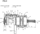
- the first housing portion 18 extends generally in the axial direction. As illustrated in Figs. 4 and 5 , a cylinder bore 24 is formed in the first housing portion 18 so as to extend therethrough in the axial direction. As illustrated in Fig. 2 , a central axis C of the cylinder bore 24 is parallel to the rotation axis L of the rotor 3.
- a first piston 30 as one example of a first pressing member and a second piston 32 as one example of a second pressing member are fluid-tightly and slidably disposed in the cylinder bore 24 via piston seals.
- a portion of the cylinder bore 24 between the first piston 30 and the second piston 32 serves as a hydraulic-pressure chamber 36.
- the first piston 30 and the second piston 32 are movable relative to each other in the axial direction.
- a portion of the first housing portion 18 in which the cylinder bore 24 is formed serves as a cylinder body.
- the wheel cylinder 14 is constituted by the cylinder body, the first piston 30, the second piston 32, etc. It is noted that a central axis of the first piston 30 and a central axis of the second piston 32 substantially coincide with the central axis C of the cylinder bore 24.
- a pair of mount portions 42, 44 are provided on opposite sides, in the circumferential direction, of a rotor-side end portion of the first housing portion 18 in the axial direction.
- the housing 10 is secured at the mount portions 42, 44 to a suspension member (which may also be referred to as "vehicle-body-side member") such as a knuckle as one example of a non-rotating member.
- a pair of pin holding holes 46, 48 are respectively formed on opposite sides, in the circumferential direction, of the cylinder bore 24 of the first housing portion 18.
- the pin holding holes 46, 48 extend in a direction parallel to the axial direction.
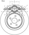
- a central axis Cp of each of the pin holding holes 46, 48 and the central axis C of the cylinder bore 24 are parallel to each other and are located on substantially the same plane N, as illustrated in Fig. 3 .
- the central axis C of the cylinder bore 24 and the central axis Cp of each of the pin holding holes 46, 48 are located at substantially the same position, as illustrated in Figs. 2 and 4 .
- the frame 16 is a rigid member generally shaped like a frame and is held by the first housing portion 18 so as to be movable in the axial direction relative to the first housing portion 18.
- the frame 16 includes: (i) a first side portion 54 and a second side portion 55 spaced apart from each other in the axial direction; and (ii) a third side portion 57 and a fourth side portion 58 coupling the first side portion 54 and the second side portion 55 to each other and spaced apart from each other in the circumferential direction.
- the first side portion 54 and the second side portion 55 extend generally in a direction orthogonal to the axial direction
- the third side portion 57 and the fourth side portion 58 extend in a direction that intersects the first side portion 54 and the second side portion 55.
- the first side portion 54 and the second side portion 55 are respectively located on opposite sides of the rotor 3 in the axial direction.
- the first side portion 54 is located on an inner side of the rotor 3 in the width direction of the vehicle and opposed to the second piston 32.
- the second side portion 55 is located on an outer side of the rotor 3 in the width direction of the vehicle and is engaged with the outer pad 6.
- the outer pad 6 is engaged with the second side portion 55 so as to be movable in the axial direction together with the second side portion 55. It is noted that the outer pad 6 is engaged with the second side portion 55 with clearances interposed therebetween in the circumferential direction.
- third side portion 57 and the fourth side portion 58 extend on the inner and outer sides of the rotor 3 in the width direction of the vehicle. As illustrated in Figs. 5 , 7, and 8 , third side portion 57 and the fourth side portion 58 extend over the rotor 3 without extending over outer circumferential surfaces of the inner pad 4 and the outer pad 6 in the radial direction.
- the frame 16 is shaped to be symmetric with respect to a symmetry plane Q that extends in the axial direction, and the plane N indicated above is substantially orthogonal to the symmetry plane Q.
- the symmetry plane Q of the frame 16 does not necessarily pass the central axis C of the cylinder bore 24.
- the symmetry plane Q may be configured to pass the central axis C and may be configured not to pass the central axis C.
- the plane N is substantially orthogonal to a plane that includes the central axis C of the cylinder bore 24 (which is identical to the central axis of the first piston 30 and the central axis of the second piston 32) and the rotation axis L.
- the pins 60, 62 are opposed to the respective pin holding holes 46, 48 formed in the first housing portion 18 such that the pins 60, 62 are movable relative to the pin holding holes 46, 48.
- the frame 16 is held by the housing 10 in such a posture that the central axis Cy of each of the pins 60, 62 substantially coincide with the central axis Cp of each of the pin holding holes 46, 48.
- the frame 16 is held by the housing 10 through the pins 60, 62 so as to be movable in the axial direction relative to the housing 10.
- the central axis C of the cylinder bore 24 (which is also the central axes of the first piston 30 and the second piston 32) and the central axis Cy of each of the pins 60, 62 are located on substantially the same plane N.
- "to be located on the same plane N” means “to be located on substantially the same plane N”. This applies to "to be located at the same position” and “orthogonal”. That is, “to be located at the same position” means “to be located at substantially the same position” and “to be orthogonal” means “to be substantially orthogonal”.
- the pin 60 includes a first pin portion 70a and a second pin portion 72a
- the pin 62 includes a first pin portion 70b and a second pin portion 72b.
- the first pin portions 70a, 70b are located at the frame 16.
- the second pin portions 72a, 72b are connected to respective portions of the corresponding first pin portions 70a, 70b that protrude from the frame 16.
- the first pin portions 70a, 70b and the second pin portions 72a, 72b are movable together with the frame 16 in the axial direction.
- an average length y1 of the first side portion 54 in the axial direction is greater than an average length y2 of the second side portion 55 in the axial direction (y1>y2), as illustrated in Figs. 5 and 6 .
- the length y2 of the second side portion 55 in the axial direction can be reduced.
- the outer side in the vehicle namely, the side in the vehicle on which the second side portion 55 is located, has more restrictions on space.
- a reduction in the length y2 of the second side portion 55 in the axial direction is effective particularly when the disc brake is mounted on a wheel equipped with an in-wheel motor.
- the length y1 of the first side portion 54 is preferably made large for enabling the frame 16 to be held by the housing 10 through the pins 60, 62.
- the length y2 of the second side portion 55 may be less than 2/3 of the length y1 of the first side portion 54 (y2 ⁇ 2*y1/3).
- the length y2 of the second side portion 55 may be less than 1/2 of the length y1 of the first side portion 54 (y2 ⁇ y1/2), may be less than 1/3 of the length y1 (y2 ⁇ y1/3), may be less than 1/4 of the length y1 (y2 ⁇ y1/4), or may be less than 1/5 of the length y1 (y2 ⁇ y1/5), for instance.
- the second side portion 55 has a cross section shaped such that an outer portion 55t has a large length in the radial direction and an inner portion 55i has a small length in the radial direction.
- This configuration allows a higher degree of flexural rigidity with respect to the force in the axial direction that acts on the second side portion 55 when the disc brake operates, as compared with a second side portion having a generally rectangular cross-sectional shape and having the same cross-sectional area as the second side portion 55.
- the cross section of the second side portion 55 is shaped to allow a higher degree of flexural rigidity, thus making it possible to reduce the axial length y2 of the second side portion 55.
- the outer portion 55t has the length in the radial direction greater than the length in the radial direction of the inner portion 55i, making it possible to enhance design of the disc brake. For instance, a logo can be put on an outer surface of the outer portion 55t.
- the frame 16 is held at the first side portion 54 by the housing 10 through the pair of pins 60, 61, thus allowing easy work of the frame 16, as compared with a case in which the frame 16 is held at the third side portion 57 and the fourth side portion 58 by the housing 10.
- the second housing portion 19 is generally shaped like a frame in plan view and includes: a pair of rods 80, 82 spaced apart from each other in the circumferential direction and extending in the axial direction; and couplers 83, 84 coupling the rods 80, 82 and extending generally in the circumferential direction.
- the inner pad 4 and the outer pad 6 are held by the rods 80, 82 so as to be movable in the axial direction.
- the rods 80, 82 respectively include a pair of protruding rail portions 90, 91 that protrude toward each other and extend in the axial direction.
- the outer pad 6 and the inner pad 4 are held at hook portions 4at, 4bt, 6at, 6bt by the pair of protruding rail portions 90, 91 (hereinafter simply referred to as "rail portions 90, 91" where appropriate).
- the rail portions 90, 91 are respectively provided at facing portions of the corresponding rods 80, 82 that face each other in the circumferential direction.
- a cutout extending in the axial direction is formed at a radially outer portion of the facing portion of each rod 80, 82, and each rail portion 90, 91 is formed at a portion of the facing portion of each rod 80, 82 that is located radially inward of the cutout.
- a leaf spring 100 as one example of an elastic member is provided to hold the inner pad 4 and the outer pad 6 at their radially outer portions such that the leaf spring 100 elastically pushes the pads 4, 6 in the radial direction and the circumferential direction.
- the leaf spring 100 is for reducing vibrations of the outer pad 6 and the inner pad 4 in the radial direction and the circumferential direction.
- the leaf spring 100 includes an intermediate portion 102 located intermediate in the axial direction, an inner-pad holder portion 104 located on the inner side of the intermediate portion 102 in the width direction of the vehicle, and an outer-pad holder portion 106 located on the outer side of the intermediate portion 102 in the width direction of the vehicle.
- the intermediate portion 102, the inner-pad holder portion 104, and the outer-pad holder portion 106 are connected to one another.
- the leaf spring 100 is held at the intermediate portion 102 by the rail portions 90, 91.
- the inner pad 4 and the outer pad 6 are held by the single leaf spring 100, resulting in a decrease in the number of components, as compared with an arrangement in which two leaf springs are used.
- the inner-pad holder portion 104 is elastically engaged with the protrusion 4a of the back board 4r of the inner pad 4 in the circumferential direction (Trailing direction) and is elastically engaged with the protrusion 4c from the outer side in the radial direction, thus resulting in a reduction of the vibrations of the inner pad 4 in the circumferential direction and the radial direction.
- the outer-pad holder portion 106 is elastically engaged with the protrusion 6a of the back board 6r of the outer pad 6 in the circumferential direction (Trailing direction) and is elastically engaged with the protrusion 6c in the radial direction.
- the leaf spring 100 holds the inner pad 4 and the outer pad 6 so as to elastically push the pads 4, 6 in the circumferential direction and the radial direction.
- the leaf spring 100 can appropriately hold the inner pad 4 and the outer pad 6 irrespective of at which position of the wheel the disc brake is mounted.
- the leaf spring 100 holds the inner pad 4 and the outer pad 6 in a state in which an elastic force is applied to the pads 4, 6 in the circumferential direction (Trailing direction).
- a pressing force i.e., the hydraulic pressure in the present embodiment
- the vibrations of the inner pad 4 and the outer pad 6 in the circumferential direction can be well reduced or prevented.
- the inner pad 4 is mounted to the second housing portion 19 in the following manner.
- the inner pad 4 taking an inclined posture is inserted between the rods 80, 82 from one side of the second housing portion 19 on which the center axis of the wheel is located while the protrusions 4a, 4b of the back board 4r are elastically deformed.
- the radially inner surfaces of the hook portions 4at, 4bt of the protrusions 4a, 4b respectively come into contact with radially outer surfaces 90h, 91h of the rail portions 90, 91.
- the inner pad 4 is held at the hook portions 4at, 4bt thereof by the rail portions 90, 91 so as to be movable in the axial direction.
- the configuration according to the present embodiment enables the inner pad 4 and the outer pad 6 to be easily held by the rods 80, 81, as compared with a configuration in which recesses are formed in the rods 80, 81 so as to correspond to the protrusions 4a, 4b, 6a, 6b formed at the respective outer circumferential portions of the inner pad 4 and the outer pad 6 and the inner pad 4 and the outer pad 6 are held such that the protrusions 4a, 4b, 6a, 6b are engaged in the respective recesses.
- the disc brake constructed as described above is operated by the hydraulic pressure in the hydraulic-pressure chamber 36 of the wheel cylinder 14.
- a force that corresponds to the hydraulic pressure in the hydraulic-pressure chamber 36 is applied to the first piston 30 and the second piston 32.
- the first piston 30 is moved toward the rotor 3 in the axial direction to press the inner pad 4 against the rotor 3.
- the second piston 32 is moved away from the rotor 3 in the axial direction to move the frame 16 in the axial direction.
- the movement of the frame 16 causes the outer pad 6 to be pressed against the rotor 3.
- the rotor 3 is pressed from its opposite sides by the inner pad 4 and the outer pad 6, so that the rotor 3 and the inner and outer pads 4, 6 are brought into frictional engagement with each other.
- the disc brake is operated to reduce rotation of the rotor 3, thereby reducing rotation of the wheel.
- rotational direction X a torque in the rotational direction X acts on the inner pad 4 and the outer pad 6, and a force Fg in the circumferential direction acts on the center of gravity Gin of the inner pad 4 and the center of gravity Gout of the outer pad 6.
- the inner pad 4 is moved in the X direction, and the bottom surface of the recess 4ax of the back board 4r comes into contact with the facing surface 90f of the rail portion 90 of the rod 80 of the second housing portion 19.
- the torque that acts on the inner pad 4 is received by the facing surface 90f of the rail portion 90 of the rod 80.
- the facing surface 90f serves as the torque receiver.
- a reaction force Ft at the facing surface (torque receiver) 90f generates a moment M that acts on the inner pad 4. Further, rotation of the inner pad 4 by the moment M is received by the radially outer surface 91h of the rail portion 91. A reaction force Fa at the radially outer surface 91h generates a moment M' that acts on the inner pad 4. The moment M' is opposite in direction to the moment M. The moment M and the moment M' reduce or prevent a change in the posture of the inner pad 4, so that the posture of the inner pad 4 is stabilized.
- the outer pad 6 As illustrated in Fig. 8 , the outer pad 6 is moved in the X direction, and the bottom surface of the recess 6ax of the back board 6r comes into contact with the facing surface 90f of the rail portion 90. The torque that acts on the outer pad 6 is received by the facing surface 90f (torque receiver).
- a reaction force Ft at the facing surface 90f (torque receiver) generates a moment M that acts on the outer pad 6. Further, rotation of the outer pad 6 by the moment M is received by the radially outer surface 91h of the rail portion 91. A reaction force Fa at the radially outer surface 90h generates a moment M'. The moment M and the moment M' reduce or prevent a change in the posture of the outer pad 6.
- the facing surface 91f of the rail portion 91 serves as the torque receiver, and the moment M is received by the radially outer surface 90h of the rail portion 90.
- the torque that acts on the inner pad 4 and the outer pad 6 is received not by the frame 16 but by the housing 10. It is thus possible to reduce or prevent the force in the circumferential direction that acts on the frame 16, so that the frame 16 can be smoothly moved in the axial direction. It is further possible to reduce or prevent the force that acts on the third side portion 57 and the fourth side portion 58. This achieves a reduction in weight of the third side portion 57 and the fourth side portion 58 and accordingly achieves a reduction in weight and cost of the frame 16 and the disc brake.
- the frame 16 is held by the housing 10 through the pins 60, 62 so as to be movable relative to the housing 10 in the axial direction.
- the central axis Cp of each of the pins 60, 62 and the central axis C of each of the first piston 30 and the second piston 32 are located on substantially the same plane and are located at substantially the same position in side view of the disc brake. This configuration enables the frame 16 to be more smoothly moved in the axial direction.
- the disc brake is not limited to the hydraulic brake but may be an electric brake operable by driving of an electric motor.
Landscapes
- Engineering & Computer Science (AREA)
- General Engineering & Computer Science (AREA)
- Mechanical Engineering (AREA)
- Braking Arrangements (AREA)
Description
- The following invention relates to a disc brake mounted on a wheel of a vehicle.
- Patent Document 1 (
Japanese Patent Application Publication No. 2017-020644 JP S63166642 A - An aspect of the present invention is directed to an improvement of a disc brake including a first pressing member and a second pressing member, and more particularly, to a technique of ensuring a smooth movement of a driving member that is moved by a movement of the second pressing member, for instance.
- In the disc brake according to the present invention, the housing includes: a first housing portion disposed on an inner side of the rotor; and a second housing portion that extends from the first housing portion to an outer side of the rotor. The second housing portion includes a pair of rods spaced apart from each other in a circumferential direction of a wheel and extending in an axial direction. The outer pad is held by a pair of rail portions of the pair of rods so as to be movable in the axial direction relative to the pair of rail portions. The pair of rail portions respectively have torque receivers configured to receive a torque that acts on the outer pad when the disc brake operates. In the present disc brake, the torque receivers are provided not for the driving member but for the second housing portion. This configuration reduces a force in the circumferential direction that acts on the driving member, thus ensuring a smooth axial movement of the driving member.
- The objects, features, advantages, and technical and industrial significance of the present invention will be better understood by reading the following detailed description of an embodiment, when considered in connection with the accompanying drawings, in which:
-
Fig. 1 is a perspective view of a disc brake according to one embodiment of the present invention; -
Fig. 2 is a side view of the disc brake; -
Fig. 3 is a rear view of the disc brake; -
Fig. 4 is a cross-sectional view of the disc brake taken along line IV-IV inFig. 6 ; -
Fig. 5 is a cross-sectional view of the disc brake; -
Fig. 6 is a view of the disc brake, illustrating components around an inner pad; -
Fig. 7 is a cross-sectional view of the disc brake taken along line VII-VII inFig. 6 ; and -
Fig. 8 is a cross-sectional view of the disc brake taken along line VIII-VIII inFig. 4 . - Referring to the drawings, there will be hereinafter described a disc brake provided for a wheel of a vehicle according to one embodiment of the present invention, The disc brake may be operated by a hydraulic pressure or may be operated by an electromagnetic drive force.
- The disc brake according to the present invention is a floating disc brake operated by a hydraulic pressure.
- As illustrated in
Figs. 1-5 , the disc brake includes: arotor 3 that is rotated together with a wheel; aninner pad 4 and anouter pad 6 respectively located on opposite sides of therotor 3; apressing device 8; and ahousing 10 holding thepressing device 8. Thepressing device 8 includes awheel cylinder 14 and aframe 16 as one example of a driving member. In the following description, a direction parallel to a rotation axis L of therotor 3 will be simply referred to as "axial direction" where appropriate. A side on which theouter pad 6 is located in the axial direction is an outer side in the vehicle, and a side on which theinner pad 4 is located in the axial direction is an inner side in the vehicle. - The
inner pad 4 includes aback board 4r and apad portion 4p (as one example of a frictionally engageable portion) held on theback board 4r. Theouter pad 6 includes aback board 6r and apad portion 6p (as another example of the frictionally engageable portion) held on theback board 6r. Thepad portion 4p of theinner pad 4 and thepad portion 6p of theouter pad 6 face therotor 3. - As illustrated in
Figs. 7 and 8 , theback board 4r includesprotrusions back board 4r at positions spaced apart from each other in a circumferential direction of the wheel. Theprotrusions back board 6r includesprotrusions back board 6r at positions spaced apart from each other in the circumferential direction. Theprotrusions protrusions corresponding protrusions respective protrusions back board 4r further includes aprotrusion 4c provided at an intermediate position of the outer circumferential portion of theback board 4r. Likewise, theback board 6r further includes aprotrusion 6c provided at an intermediate position of the outer circumferential portion of theback board 6r. The top portion of eachprotrusion - As illustrated in
Figs. 1 and6 , thehousing 10 includes: afirst housing portion 18 located on an inner side of therotor 3 in a width direction of the vehicle; and asecond housing portion 19 fixed to thefirst housing portion 18 and extending from the inner side of therotor 3 toward an outside of the vehicle over therotor 3. - The
first housing portion 18 extends generally in the axial direction. As illustrated inFigs. 4 and5 , acylinder bore 24 is formed in thefirst housing portion 18 so as to extend therethrough in the axial direction. As illustrated inFig. 2 , a central axis C of thecylinder bore 24 is parallel to the rotation axis L of therotor 3. Afirst piston 30 as one example of a first pressing member and asecond piston 32 as one example of a second pressing member are fluid-tightly and slidably disposed in thecylinder bore 24 via piston seals. A portion of the cylinder bore 24 between thefirst piston 30 and thesecond piston 32 serves as a hydraulic-pressure chamber 36. Thefirst piston 30 and thesecond piston 32 are movable relative to each other in the axial direction. - In the present invention, a portion of the
first housing portion 18 in which thecylinder bore 24 is formed serves as a cylinder body. Thewheel cylinder 14 is constituted by the cylinder body, thefirst piston 30, thesecond piston 32, etc. It is noted that a central axis of thefirst piston 30 and a central axis of thesecond piston 32 substantially coincide with the central axis C of thecylinder bore 24. - As illustrated in
Figs. 1 and3 , a pair ofmount portions first housing portion 18 in the axial direction. Thehousing 10 is secured at themount portions - As illustrated in
Fig. 5 , a pair ofpin holding holes first housing portion 18. Thepin holding holes pin holding holes cylinder bore 24 are parallel to each other and are located on substantially the same plane N, as illustrated inFig. 3 . In side view of the present disc brake, the central axis C of the cylinder bore 24 and the central axis Cp of each of thepin holding holes Figs. 2 and4 . - As illustrated in
Figs. 1 ,5 , and6 , theframe 16 is a rigid member generally shaped like a frame and is held by thefirst housing portion 18 so as to be movable in the axial direction relative to thefirst housing portion 18. - The
frame 16 includes: (i) afirst side portion 54 and asecond side portion 55 spaced apart from each other in the axial direction; and (ii) athird side portion 57 and afourth side portion 58 coupling thefirst side portion 54 and thesecond side portion 55 to each other and spaced apart from each other in the circumferential direction. In the present embodiment, thefirst side portion 54 and thesecond side portion 55 extend generally in a direction orthogonal to the axial direction, and thethird side portion 57 and thefourth side portion 58 extend in a direction that intersects thefirst side portion 54 and thesecond side portion 55. - The
first side portion 54 and thesecond side portion 55 are respectively located on opposite sides of therotor 3 in the axial direction. Thefirst side portion 54 is located on an inner side of therotor 3 in the width direction of the vehicle and opposed to thesecond piston 32. Thesecond side portion 55 is located on an outer side of therotor 3 in the width direction of the vehicle and is engaged with theouter pad 6. In the present embodiment, theouter pad 6 is engaged with thesecond side portion 55 so as to be movable in the axial direction together with thesecond side portion 55. It is noted that theouter pad 6 is engaged with thesecond side portion 55 with clearances interposed therebetween in the circumferential direction. - The
third side portion 57 and thefourth side portion 58 extend on the inner and outer sides of therotor 3 in the width direction of the vehicle. As illustrated inFigs. 5 ,7, and 8 ,third side portion 57 and thefourth side portion 58 extend over therotor 3 without extending over outer circumferential surfaces of theinner pad 4 and theouter pad 6 in the radial direction. - As illustrated in
Figs. 1 ,3 ,5 ,6 , and7 , for instance, theframe 16 is shaped to be symmetric with respect to a symmetry plane Q that extends in the axial direction, and the plane N indicated above is substantially orthogonal to the symmetry plane Q. - The symmetry plane Q of the
frame 16 does not necessarily pass the central axis C of the cylinder bore 24. The symmetry plane Q may be configured to pass the central axis C and may be configured not to pass the central axis C. It may be considered that the plane N is substantially orthogonal to a plane that includes the central axis C of the cylinder bore 24 (which is identical to the central axis of thefirst piston 30 and the central axis of the second piston 32) and the rotation axis L. - As illustrated in
Figs. 3 and5 , a pair ofpins rotor 3 are mounted to thefirst side portion 54 of theframe 16 at positions that are symmetric with respect to the symmetry plane Q, namely, at positions that are respectively distant from the symmetry plane Q by an equivalent distance (z=z). Thepins pin holding holes first housing portion 18 such that thepins pin holding holes frame 16 is held by thehousing 10 in such a posture that the central axis Cy of each of thepins pin holding holes frame 16 is held by thehousing 10 through thepins housing 10. - In a state in which the
frame 16 is mounted on thehousing 10, the central axis C of the cylinder bore 24 (which is also the central axes of thefirst piston 30 and the second piston 32) and the central axis Cy of each of thepins - The
pin 60 includes afirst pin portion 70a and asecond pin portion 72a, and thepin 62 includes afirst pin portion 70b and asecond pin portion 72b. Thefirst pin portions frame 16. Thesecond pin portions first pin portions frame 16. Thefirst pin portions second pin portions frame 16 in the axial direction. - In plan view, an average length y1 of the
first side portion 54 in the axial direction is greater than an average length y2 of thesecond side portion 55 in the axial direction (y1>y2), as illustrated inFigs. 5 and6 . In a case where theframe 16 is designed such that the rigidity required with respect to a force in the axial direction is obtained mainly by thefirst side portion 54, the length y2 of thesecond side portion 55 in the axial direction can be reduced. The outer side in the vehicle, namely, the side in the vehicle on which thesecond side portion 55 is located, has more restrictions on space. Thus, a reduction in the length y2 of thesecond side portion 55 in the axial direction is effective particularly when the disc brake is mounted on a wheel equipped with an in-wheel motor. - The length y1 of the
first side portion 54 is preferably made large for enabling theframe 16 to be held by thehousing 10 through thepins - For instance, the length y2 of the
second side portion 55 may be less than 2/3 of the length y1 of the first side portion 54 (y2<2*y1/3). The length y2 of thesecond side portion 55 may be less than 1/2 of the length y1 of the first side portion 54 (y2<y1/2), may be less than 1/3 of the length y1 (y2<y1/3), may be less than 1/4 of the length y1 (y2<y1/4), or may be less than 1/5 of the length y1 (y2<y1/5), for instance. - As illustrated in
Fig. 4 , thesecond side portion 55 has a cross section shaped such that anouter portion 55t has a large length in the radial direction and aninner portion 55i has a small length in the radial direction. This configuration allows a higher degree of flexural rigidity with respect to the force in the axial direction that acts on thesecond side portion 55 when the disc brake operates, as compared with a second side portion having a generally rectangular cross-sectional shape and having the same cross-sectional area as thesecond side portion 55. In other words, the cross section of thesecond side portion 55 is shaped to allow a higher degree of flexural rigidity, thus making it possible to reduce the axial length y2 of thesecond side portion 55. Further, theouter portion 55t has the length in the radial direction greater than the length in the radial direction of theinner portion 55i, making it possible to enhance design of the disc brake. For instance, a logo can be put on an outer surface of theouter portion 55t. - The
frame 16 is held at thefirst side portion 54 by thehousing 10 through the pair ofpins 60, 61, thus allowing easy work of theframe 16, as compared with a case in which theframe 16 is held at thethird side portion 57 and thefourth side portion 58 by thehousing 10. - As illustrated in
Figs. 1 and6 , for instance, thesecond housing portion 19 is generally shaped like a frame in plan view and includes: a pair ofrods couplers rods Figs. 7 and 8 , theinner pad 4 and theouter pad 6 are held by therods - In the present invention, the
rods rail portions outer pad 6 and theinner pad 4 are held at hook portions 4at, 4bt, 6at, 6bt by the pair of protrudingrail portions 90, 91 (hereinafter simply referred to as "rail portions rail portions rods rod rail portion rod - In a state in which the
inner pad 4 and theouter pad 6 are held at the hook portions 4at, 4bt, 6at, 6bt by therail portions surface 90f of therail portion 90, and a slight clearance is left: between a bottom surface of each recess 4bx, 6bx and a facingsurface 91f of therail portion 91. The facingsurfaces respective rail portions - In the present invention, a
leaf spring 100 as one example of an elastic member is provided to hold theinner pad 4 and theouter pad 6 at their radially outer portions such that theleaf spring 100 elastically pushes thepads Figs. 1 and6 , theleaf spring 100 is for reducing vibrations of theouter pad 6 and theinner pad 4 in the radial direction and the circumferential direction. Theleaf spring 100 includes anintermediate portion 102 located intermediate in the axial direction, an inner-pad holder portion 104 located on the inner side of theintermediate portion 102 in the width direction of the vehicle, and an outer-pad holder portion 106 located on the outer side of theintermediate portion 102 in the width direction of the vehicle. Theintermediate portion 102, the inner-pad holder portion 104, and the outer-pad holder portion 106 are connected to one another. Theleaf spring 100 is held at theintermediate portion 102 by therail portions inner pad 4 and theouter pad 6 are held by thesingle leaf spring 100, resulting in a decrease in the number of components, as compared with an arrangement in which two leaf springs are used. - As illustrated in
Figs. 1 ,4 ,7, and 8 , the inner-pad holder portion 104 is elastically engaged with theprotrusion 4a of theback board 4r of theinner pad 4 in the circumferential direction (Trailing direction) and is elastically engaged with theprotrusion 4c from the outer side in the radial direction, thus resulting in a reduction of the vibrations of theinner pad 4 in the circumferential direction and the radial direction. Likewise, the outer-pad holder portion 106 is elastically engaged with theprotrusion 6a of theback board 6r of theouter pad 6 in the circumferential direction (Trailing direction) and is elastically engaged with theprotrusion 6c in the radial direction. - As described above, the
leaf spring 100 holds theinner pad 4 and theouter pad 6 so as to elastically push thepads leaf spring 100 can appropriately hold theinner pad 4 and theouter pad 6 irrespective of at which position of the wheel the disc brake is mounted. - The
leaf spring 100 holds theinner pad 4 and theouter pad 6 in a state in which an elastic force is applied to thepads inner pad 4 and theouter pad 6 are pressed against therotor 3 in the operation of the disc brake, is small, the vibrations of theinner pad 4 and theouter pad 6 in the circumferential direction can be well reduced or prevented. - The
inner pad 4 is mounted to thesecond housing portion 19 in the following manner. Theinner pad 4 taking an inclined posture is inserted between therods second housing portion 19 on which the center axis of the wheel is located while theprotrusions back board 4r are elastically deformed. The radially inner surfaces of the hook portions 4at, 4bt of theprotrusions outer surfaces rail portions inner pad 4 is held at the hook portions 4at, 4bt thereof by therail portions outer pad 6. - As described above, the
inner pad 4 and theouter pad 6 are held by therods 80, 81 utilizing therail portions inner pad 4 and theouter pad 6 to be easily held by therods 80, 81, as compared with a configuration in which recesses are formed in therods 80, 81 so as to correspond to theprotrusions inner pad 4 and theouter pad 6 and theinner pad 4 and theouter pad 6 are held such that theprotrusions - In the present invention, it is simply required that the hook portions 4at, 4bt of the
inner pad 4 and the hook portions 6at, 6bt of theouter pad 6 are engaged with therail portions rail portions - The disc brake constructed as described above is operated by the hydraulic pressure in the hydraulic-
pressure chamber 36 of thewheel cylinder 14. A force that corresponds to the hydraulic pressure in the hydraulic-pressure chamber 36 is applied to thefirst piston 30 and thesecond piston 32. Thefirst piston 30 is moved toward therotor 3 in the axial direction to press theinner pad 4 against therotor 3. Thesecond piston 32 is moved away from therotor 3 in the axial direction to move theframe 16 in the axial direction. The movement of theframe 16 causes theouter pad 6 to be pressed against therotor 3. Therotor 3 is pressed from its opposite sides by theinner pad 4 and theouter pad 6, so that therotor 3 and the inner andouter pads rotor 3, thereby reducing rotation of the wheel. - In a case where the disc brake is operated when the wheel is rotating in a direction indicated by an arrow X in
Figs. 7 and 8 (hereinafter referred to as "rotational direction X" where appropriate), a torque in the rotational direction X acts on theinner pad 4 and theouter pad 6, and a force Fg in the circumferential direction acts on the center of gravity Gin of theinner pad 4 and the center of gravity Gout of theouter pad 6. - As illustrated in
Fig. 7 , theinner pad 4 is moved in the X direction, and the bottom surface of the recess 4ax of theback board 4r comes into contact with the facingsurface 90f of therail portion 90 of therod 80 of thesecond housing portion 19. The torque that acts on theinner pad 4 is received by the facingsurface 90f of therail portion 90 of therod 80. Thus, the facingsurface 90f serves as the torque receiver. - A reaction force Ft at the facing surface (torque receiver) 90f generates a moment M that acts on the
inner pad 4. Further, rotation of theinner pad 4 by the moment M is received by the radiallyouter surface 91h of therail portion 91. A reaction force Fa at the radiallyouter surface 91h generates a moment M' that acts on theinner pad 4. The moment M' is opposite in direction to the moment M. The moment M and the moment M' reduce or prevent a change in the posture of theinner pad 4, so that the posture of theinner pad 4 is stabilized. - The same applies to the
outer pad 6. As illustrated inFig. 8 , theouter pad 6 is moved in the X direction, and the bottom surface of the recess 6ax of theback board 6r comes into contact with the facingsurface 90f of therail portion 90. The torque that acts on theouter pad 6 is received by the facingsurface 90f (torque receiver). - A reaction force Ft at the facing
surface 90f (torque receiver) generates a moment M that acts on theouter pad 6. Further, rotation of theouter pad 6 by the moment M is received by the radiallyouter surface 91h of therail portion 91. A reaction force Fa at the radiallyouter surface 90h generates a moment M'. The moment M and the moment M' reduce or prevent a change in the posture of theouter pad 6. - In a case where the wheel is rotated in a direction opposite to the X direction described above, the facing
surface 91f of therail portion 91 serves as the torque receiver, and the moment M is received by the radiallyouter surface 90h of therail portion 90. - The torque that acts on the
inner pad 4 and theouter pad 6 is received not by theframe 16 but by thehousing 10. It is thus possible to reduce or prevent the force in the circumferential direction that acts on theframe 16, so that theframe 16 can be smoothly moved in the axial direction. It is further possible to reduce or prevent the force that acts on thethird side portion 57 and thefourth side portion 58. This achieves a reduction in weight of thethird side portion 57 and thefourth side portion 58 and accordingly achieves a reduction in weight and cost of theframe 16 and the disc brake. - The
frame 16 is held by thehousing 10 through thepins housing 10 in the axial direction. The central axis Cp of each of thepins first piston 30 and thesecond piston 32 are located on substantially the same plane and are located at substantially the same position in side view of the disc brake. This configuration enables theframe 16 to be more smoothly moved in the axial direction. - It is to be understood that the present invention is not limited to the details of the illustrated embodiment but may be embodied with various changes and modifications, which may occur to those skilled in the art, without departing from the scope of the invention within the scope of the appended claims. For instance, the disc brake is not limited to the hydraulic brake but may be an electric brake operable by driving of an electric motor.
Claims (9)
- A disc brake of a floating type, comprising:an inner pad (4) and an outer pad (6) respectively located on opposite sides of a rotor (3) rotatable with a wheel of a vehicle;a pressing device (8) configured to press the inner pad (4) and the outer pad (6) against the rotor (3); anda housing (10) mounted on a non-rotating member and holding the pressing device (8),wherein the pressing device (8) includes:one or more first pressing members (30) held by the housing (10) and movable toward the rotor (3) and one or more second pressing members (32) held by the housing (10) and movable away from the rotor (3); anda driving member (16) held by the housing (10) so as to be movable relative to the housing (10) in an axial direction parallel to a rotation axis of the rotor (3), the driving member (16) being configured to be moved by a movement of the one or more second pressing members (32) to press the outer pad (6) against the rotor (3),wherein the housing (10) includes: a first housing portion (18) disposed on an inner side of the rotor (3) in a width direction of the vehicle and holding the one or more first pressing members (30) and the one or more second pressing members (32); and a second housing portion (19) extending from the first housing portion (18) to an outer side of the rotor (3) in the width direction of the vehicle,wherein the second housing portion (19) includes a pair of rods (80, 82) spaced apart from each other in a circumferential direction of the wheel and extending in the axial direction, the pair of rods (80, 82) respectively including facing portions that face each other in the circumferential direction, each of the pair of rods (80, 82) including a rail portion (90, 91) provided at the facing portion so as to extend in the axial direction, the rail portions (90, 91) of the pair of rods (80, 82) constituting a pair of rail portions (90, 91), andwherein the outer pad (6) is held by the pair of rail portions (90, 91) so as to be movable in the axial direction relative to the pair of rail portions (90, 91), and the pair of rail portions (90, 91) respectively have torque receivers (90f, 91f) configured to receive a torque that acts on the outer pad (6).
- The disc brake according to claim 1,wherein the outer pad (6) includes a pair of protrusions (6a, 6b) provided on an outer circumferential portion of the outer pad (6) at positions spaced apart from each other in the circumferential direction, so as to protrude outward in a radial direction of the wheel, andwherein the pair of protrusions (6a, 6b) are engaged respectively with the pair of rail portions (90, 91) to allow the outer pad (6) to be held by the pair of rail portions (90, 91).
- The disc brake according to claim 1 or 2,wherein the inner pad (4) is held by the pair of rail portions (90, 91) so as to be movable in the axial direction relative to the pair of rail portions (90, 91),wherein the disc brake includes an elastic member (100) configured to elastically push the inner pad (4) and the outer pad (6) in a radial direction of the wheel and the circumferential direction, andwherein the elastic member (100) is held at the pair of rail portions (90, 91).
- The disc brake according to any one of claims 1 through 3,wherein the driving member (16) includes a plurality of pins (60, 62) extending in the axial direction and spaced apart from each other in the circumferential direction, the driving member (16) being held by the housing (10) through the plurality of pins (60, 62) so as to be movable in the axial direction relative to the housing (10), andwherein a central axis of each of the plurality of pins (60, 62), a central axis of each of the one or more first pressing members (30), and a central axis of each of the one or more second pressing members (32) are located on one plane.
- The disc brake according to claim 4,wherein the driving member (16) is shaped to be symmetric with respect to a symmetry plane that extends in a direction parallel to the axial direction, andwherein the one plane extends so as to be orthogonal to the symmetry plane of the driving member (16).
- The disc brake according to claim 5,wherein a pair of pins (60, 62) as the plurality of pins (60, 62) are provided at positions of the driving member (16) that are symmetric with respect to the symmetry plane, andwherein a pair of pin holding holes (46, 48) are formed at portions of the housing (10) that are spaced apart from each other in the circumferential direction, the pair of pin holding holes (46, 48) extending in the axial direction so as to be parallel to each other.
- The disc brake according to any one of claims 1 through 6,wherein the driving member (16) includes a first side portion (54) facing the one or more second pressing members (32) and a second side portion (55) facing the outer pad (6), andwherein the second side portion (55) has a length in the axial direction less than a length in the axial direction of the first side portion (54).
- The disc brake according to claim 7, wherein the length in the axial direction of the second side portion (55) is less than 1/3 of the length in the axial direction of the first side portion (54).
- The disc brake according to claim 7 or 8, wherein the second side portion (55) has a cross section shaped such that an outer portion of the second side portion (55) in the width direction of the vehicle is greater in a radial direction of the wheel than a portion of the second side portion (55) facing the outer pad (6).
Applications Claiming Priority (1)
| Application Number | Priority Date | Filing Date | Title |
|---|---|---|---|
| JP2021019108A JP7444095B2 (en) | 2021-02-09 | 2021-02-09 | disc brake |
Publications (2)
| Publication Number | Publication Date |
|---|---|
| EP4040003A1 EP4040003A1 (en) | 2022-08-10 |
| EP4040003B1 true EP4040003B1 (en) | 2024-03-27 |
Family
ID=79730138
Family Applications (1)
| Application Number | Title | Priority Date | Filing Date |
|---|---|---|---|
| EP22152148.7A Revoked EP4040003B1 (en) | 2021-02-09 | 2022-01-19 | Disc brake |
Country Status (4)
| Country | Link |
|---|---|
| US (1) | US20220252116A1 (en) |
| EP (1) | EP4040003B1 (en) |
| JP (1) | JP7444095B2 (en) |
| CN (1) | CN114909412B (en) |
Citations (8)
| Publication number | Priority date | Publication date | Assignee | Title |
|---|---|---|---|---|
| US4074795A (en) | 1974-10-01 | 1978-02-21 | Aisin Seiki Kabushiki Kaisha | Caliper mounting arrangement for a disc brake |
| US4171037A (en) | 1977-06-30 | 1979-10-16 | Toyota Jidosha Kogyo Kabushiki Kaisha | Car disc brake improved in friction pad mounting |
| FR2432650A1 (en) | 1978-08-01 | 1980-02-29 | Kelsey Hayes Co | Disc brake spring clip - has axial sections pressing shoes against guide arm surfaces and hooked portion |
| US4632227A (en) | 1983-12-15 | 1986-12-30 | Societe Anonyme D.B.A. | Pad and torque support assembly for disc brake |
| EP0341392B1 (en) | 1988-05-07 | 1993-06-23 | ALFRED TEVES GmbH | Spot-type disc brake |
| EP0700486B1 (en) | 1993-06-05 | 2001-10-10 | Continental Teves AG & Co. oHG | Floating caliper disc brake for motor vehicles |
| EP3495682A1 (en) | 2017-12-08 | 2019-06-12 | Toyota Jidosha Kabushiki Kaisha | Disc brake |
| US20200325945A1 (en) | 2019-04-10 | 2020-10-15 | Toyota Jidosha Kabushiki Kaisha | Disc brake |
Family Cites Families (12)
| Publication number | Priority date | Publication date | Assignee | Title |
|---|---|---|---|---|
| GB1107209A (en) * | 1965-11-20 | 1968-03-27 | Girling Holdings Ltd | Improvements in disc brakes |
| FR1534085A (en) * | 1967-06-16 | 1968-07-26 | Ferodo Sa | Improvements to disc brakes |
| SE376283B (en) * | 1969-07-11 | 1975-05-12 | Ferodo Sa | |
| ES8300389A1 (en) * | 1981-12-14 | 1982-11-01 | Bendiberica Sa | Disc brake with a slidable caliper. |
| JPH0678057B2 (en) * | 1985-04-25 | 1994-10-05 | 富士重工業株式会社 | Breaking device |
| JPS63166642A (en) * | 1986-12-29 | 1988-07-09 | Nippon Air Brake Co Ltd | Brake control drive |
| JP2562026B2 (en) * | 1987-03-07 | 1996-12-11 | 株式会社ナブコ | Disk breaker |
| DE102010043320A1 (en) * | 2010-11-03 | 2012-05-03 | Continental Teves Ag & Co. Ohg | Apparatus and method for determining a measure of an effective braking force or friction force on a disc brake |
| CN102562871B (en) * | 2012-02-24 | 2013-09-25 | 吉林大学 | Design method of wedge-shaped self-energizing disc brake |
| JP6680554B2 (en) | 2015-07-09 | 2020-04-15 | 曙ブレーキ工業株式会社 | Disc brake device |
| JP6950503B2 (en) * | 2017-12-08 | 2021-10-13 | トヨタ自動車株式会社 | Hydraulic braking system |
| JP7124686B2 (en) * | 2018-12-17 | 2022-08-24 | トヨタ自動車株式会社 | disc brake device |
-
2021
- 2021-02-09 JP JP2021019108A patent/JP7444095B2/en active Active
-
2022
- 2022-01-19 EP EP22152148.7A patent/EP4040003B1/en not_active Revoked
- 2022-01-25 CN CN202210085431.7A patent/CN114909412B/en active Active
- 2022-02-04 US US17/665,090 patent/US20220252116A1/en not_active Abandoned
Patent Citations (8)
| Publication number | Priority date | Publication date | Assignee | Title |
|---|---|---|---|---|
| US4074795A (en) | 1974-10-01 | 1978-02-21 | Aisin Seiki Kabushiki Kaisha | Caliper mounting arrangement for a disc brake |
| US4171037A (en) | 1977-06-30 | 1979-10-16 | Toyota Jidosha Kogyo Kabushiki Kaisha | Car disc brake improved in friction pad mounting |
| FR2432650A1 (en) | 1978-08-01 | 1980-02-29 | Kelsey Hayes Co | Disc brake spring clip - has axial sections pressing shoes against guide arm surfaces and hooked portion |
| US4632227A (en) | 1983-12-15 | 1986-12-30 | Societe Anonyme D.B.A. | Pad and torque support assembly for disc brake |
| EP0341392B1 (en) | 1988-05-07 | 1993-06-23 | ALFRED TEVES GmbH | Spot-type disc brake |
| EP0700486B1 (en) | 1993-06-05 | 2001-10-10 | Continental Teves AG & Co. oHG | Floating caliper disc brake for motor vehicles |
| EP3495682A1 (en) | 2017-12-08 | 2019-06-12 | Toyota Jidosha Kabushiki Kaisha | Disc brake |
| US20200325945A1 (en) | 2019-04-10 | 2020-10-15 | Toyota Jidosha Kabushiki Kaisha | Disc brake |
Also Published As
| Publication number | Publication date |
|---|---|
| US20220252116A1 (en) | 2022-08-11 |
| JP7444095B2 (en) | 2024-03-06 |
| EP4040003A1 (en) | 2022-08-10 |
| JP2022122051A (en) | 2022-08-22 |
| CN114909412B (en) | 2025-02-28 |
| CN114909412A (en) | 2022-08-16 |
Similar Documents
| Publication | Publication Date | Title |
|---|---|---|
| US10913433B2 (en) | Disc brake | |
| CN109591882B (en) | Rear wheel steering gear, vehicle and rear wheel steering system thereof | |
| CN109591881B (en) | Rear wheel steering gear, vehicle and rear wheel steering system thereof | |
| US20090283372A1 (en) | Disc brake device | |
| WO2007087393A2 (en) | Symmetric brake clip | |
| CN106030131A (en) | Bearing of a lever, which is provided with a pivot arm, in relation to a pressure piece | |
| CN104246276A (en) | Friction pad assembly for disk brake | |
| JP2015124812A (en) | Disc brake device | |
| CA1221040A (en) | Spring for a disc brake | |
| US20200109751A1 (en) | Disc brake | |
| EP4040003B1 (en) | Disc brake | |
| US11396918B2 (en) | Disc brake | |
| JPH07305734A (en) | Disc brake | |
| US11078976B2 (en) | Disc brake | |
| CN215618083U (en) | Electromagnetic brake module and joint actuator of robot | |
| US11221050B2 (en) | Disc brake | |
| CN117212366A (en) | Caliper-biased electromechanical braking devices, systems and vehicles | |
| JP4880250B2 (en) | Vehicle disc brake | |
| CN213870842U (en) | Clamp body assembly, air pressure disc brake, axle and commercial vehicle | |
| WO2024116541A1 (en) | Disc brake | |
| CN110194027B (en) | Wheel assembly and vehicle | |
| US20200011386A1 (en) | Disc brake | |
| US20240263679A1 (en) | Disc brake and pad spring | |
| US20180180120A1 (en) | Brake module | |
| JPH08159188A (en) | Disc brake |
Legal Events
| Date | Code | Title | Description |
|---|---|---|---|
| PUAI | Public reference made under article 153(3) epc to a published international application that has entered the european phase |
Free format text: ORIGINAL CODE: 0009012 |
|
| STAA | Information on the status of an ep patent application or granted ep patent |
Free format text: STATUS: REQUEST FOR EXAMINATION WAS MADE |
|
| 17P | Request for examination filed |
Effective date: 20220119 |
|
| AK | Designated contracting states |
Kind code of ref document: A1 Designated state(s): AL AT BE BG CH CY CZ DE DK EE ES FI FR GB GR HR HU IE IS IT LI LT LU LV MC MK MT NL NO PL PT RO RS SE SI SK SM TR |
|
| GRAP | Despatch of communication of intention to grant a patent |
Free format text: ORIGINAL CODE: EPIDOSNIGR1 |
|
| RIC1 | Information provided on ipc code assigned before grant |
Ipc: F16D 65/18 20060101ALI20231113BHEP Ipc: F16D 55/22 20060101AFI20231113BHEP |
|
| STAA | Information on the status of an ep patent application or granted ep patent |
Free format text: STATUS: GRANT OF PATENT IS INTENDED |
|
| INTG | Intention to grant announced |
Effective date: 20231221 |
|
| GRAS | Grant fee paid |
Free format text: ORIGINAL CODE: EPIDOSNIGR3 |
|
| GRAA | (expected) grant |
Free format text: ORIGINAL CODE: 0009210 |
|
| STAA | Information on the status of an ep patent application or granted ep patent |
Free format text: STATUS: THE PATENT HAS BEEN GRANTED |
|
| AK | Designated contracting states |
Kind code of ref document: B1 Designated state(s): AL AT BE BG CH CY CZ DE DK EE ES FI FR GB GR HR HU IE IS IT LI LT LU LV MC MK MT NL NO PL PT RO RS SE SI SK SM TR |
|
| REG | Reference to a national code |
Ref country code: GB Ref legal event code: FG4D |
|
| REG | Reference to a national code |
Ref country code: CH Ref legal event code: EP |
|
| REG | Reference to a national code |
Ref country code: DE Ref legal event code: R096 Ref document number: 602022002475 Country of ref document: DE |
|
| REG | Reference to a national code |
Ref country code: IE Ref legal event code: FG4D |
|
| P01 | Opt-out of the competence of the unified patent court (upc) registered |
Effective date: 20240419 |
|
| REG | Reference to a national code |
Ref country code: DE Ref legal event code: R084 Ref document number: 602022002475 Country of ref document: DE |
|
| PG25 | Lapsed in a contracting state [announced via postgrant information from national office to epo] |
Ref country code: LT Free format text: LAPSE BECAUSE OF FAILURE TO SUBMIT A TRANSLATION OF THE DESCRIPTION OR TO PAY THE FEE WITHIN THE PRESCRIBED TIME-LIMIT Effective date: 20240327 |
|
| REG | Reference to a national code |
Ref country code: LT Ref legal event code: MG9D |
|
| PG25 | Lapsed in a contracting state [announced via postgrant information from national office to epo] |
Ref country code: GR Free format text: LAPSE BECAUSE OF FAILURE TO SUBMIT A TRANSLATION OF THE DESCRIPTION OR TO PAY THE FEE WITHIN THE PRESCRIBED TIME-LIMIT Effective date: 20240628 |
|
| REG | Reference to a national code |
Ref country code: GB Ref legal event code: 746 Effective date: 20240627 |
|
| PG25 | Lapsed in a contracting state [announced via postgrant information from national office to epo] |
Ref country code: RS Free format text: LAPSE BECAUSE OF FAILURE TO SUBMIT A TRANSLATION OF THE DESCRIPTION OR TO PAY THE FEE WITHIN THE PRESCRIBED TIME-LIMIT Effective date: 20240627 Ref country code: HR Free format text: LAPSE BECAUSE OF FAILURE TO SUBMIT A TRANSLATION OF THE DESCRIPTION OR TO PAY THE FEE WITHIN THE PRESCRIBED TIME-LIMIT Effective date: 20240327 |
|
| PG25 | Lapsed in a contracting state [announced via postgrant information from national office to epo] |
Ref country code: RS Free format text: LAPSE BECAUSE OF FAILURE TO SUBMIT A TRANSLATION OF THE DESCRIPTION OR TO PAY THE FEE WITHIN THE PRESCRIBED TIME-LIMIT Effective date: 20240627 Ref country code: NO Free format text: LAPSE BECAUSE OF FAILURE TO SUBMIT A TRANSLATION OF THE DESCRIPTION OR TO PAY THE FEE WITHIN THE PRESCRIBED TIME-LIMIT Effective date: 20240627 Ref country code: LT Free format text: LAPSE BECAUSE OF FAILURE TO SUBMIT A TRANSLATION OF THE DESCRIPTION OR TO PAY THE FEE WITHIN THE PRESCRIBED TIME-LIMIT Effective date: 20240327 Ref country code: HR Free format text: LAPSE BECAUSE OF FAILURE TO SUBMIT A TRANSLATION OF THE DESCRIPTION OR TO PAY THE FEE WITHIN THE PRESCRIBED TIME-LIMIT Effective date: 20240327 Ref country code: GR Free format text: LAPSE BECAUSE OF FAILURE TO SUBMIT A TRANSLATION OF THE DESCRIPTION OR TO PAY THE FEE WITHIN THE PRESCRIBED TIME-LIMIT Effective date: 20240628 Ref country code: FI Free format text: LAPSE BECAUSE OF FAILURE TO SUBMIT A TRANSLATION OF THE DESCRIPTION OR TO PAY THE FEE WITHIN THE PRESCRIBED TIME-LIMIT Effective date: 20240327 Ref country code: BG Free format text: LAPSE BECAUSE OF FAILURE TO SUBMIT A TRANSLATION OF THE DESCRIPTION OR TO PAY THE FEE WITHIN THE PRESCRIBED TIME-LIMIT Effective date: 20240327 |
|
| REG | Reference to a national code |
Ref country code: NL Ref legal event code: MP Effective date: 20240327 |
|
| PG25 | Lapsed in a contracting state [announced via postgrant information from national office to epo] |
Ref country code: SE Free format text: LAPSE BECAUSE OF FAILURE TO SUBMIT A TRANSLATION OF THE DESCRIPTION OR TO PAY THE FEE WITHIN THE PRESCRIBED TIME-LIMIT Effective date: 20240327 Ref country code: LV Free format text: LAPSE BECAUSE OF FAILURE TO SUBMIT A TRANSLATION OF THE DESCRIPTION OR TO PAY THE FEE WITHIN THE PRESCRIBED TIME-LIMIT Effective date: 20240327 |
|
| PG25 | Lapsed in a contracting state [announced via postgrant information from national office to epo] |
Ref country code: NL Free format text: LAPSE BECAUSE OF FAILURE TO SUBMIT A TRANSLATION OF THE DESCRIPTION OR TO PAY THE FEE WITHIN THE PRESCRIBED TIME-LIMIT Effective date: 20240327 |
|
| REG | Reference to a national code |
Ref country code: AT Ref legal event code: MK05 Ref document number: 1670194 Country of ref document: AT Kind code of ref document: T Effective date: 20240327 |
|
| PG25 | Lapsed in a contracting state [announced via postgrant information from national office to epo] |
Ref country code: NL Free format text: LAPSE BECAUSE OF FAILURE TO SUBMIT A TRANSLATION OF THE DESCRIPTION OR TO PAY THE FEE WITHIN THE PRESCRIBED TIME-LIMIT Effective date: 20240327 |
|
| PG25 | Lapsed in a contracting state [announced via postgrant information from national office to epo] |
Ref country code: IS Free format text: LAPSE BECAUSE OF FAILURE TO SUBMIT A TRANSLATION OF THE DESCRIPTION OR TO PAY THE FEE WITHIN THE PRESCRIBED TIME-LIMIT Effective date: 20240727 |
|
| PG25 | Lapsed in a contracting state [announced via postgrant information from national office to epo] |
Ref country code: PT Free format text: LAPSE BECAUSE OF FAILURE TO SUBMIT A TRANSLATION OF THE DESCRIPTION OR TO PAY THE FEE WITHIN THE PRESCRIBED TIME-LIMIT Effective date: 20240729 Ref country code: SM Free format text: LAPSE BECAUSE OF FAILURE TO SUBMIT A TRANSLATION OF THE DESCRIPTION OR TO PAY THE FEE WITHIN THE PRESCRIBED TIME-LIMIT Effective date: 20240327 |
|
| PG25 | Lapsed in a contracting state [announced via postgrant information from national office to epo] |
Ref country code: ES Free format text: LAPSE BECAUSE OF FAILURE TO SUBMIT A TRANSLATION OF THE DESCRIPTION OR TO PAY THE FEE WITHIN THE PRESCRIBED TIME-LIMIT Effective date: 20240327 |
|
| PG25 | Lapsed in a contracting state [announced via postgrant information from national office to epo] |
Ref country code: EE Free format text: LAPSE BECAUSE OF FAILURE TO SUBMIT A TRANSLATION OF THE DESCRIPTION OR TO PAY THE FEE WITHIN THE PRESCRIBED TIME-LIMIT Effective date: 20240327 Ref country code: CZ Free format text: LAPSE BECAUSE OF FAILURE TO SUBMIT A TRANSLATION OF THE DESCRIPTION OR TO PAY THE FEE WITHIN THE PRESCRIBED TIME-LIMIT Effective date: 20240327 |
|
| PG25 | Lapsed in a contracting state [announced via postgrant information from national office to epo] |
Ref country code: AT Free format text: LAPSE BECAUSE OF FAILURE TO SUBMIT A TRANSLATION OF THE DESCRIPTION OR TO PAY THE FEE WITHIN THE PRESCRIBED TIME-LIMIT Effective date: 20240327 |
|
| PG25 | Lapsed in a contracting state [announced via postgrant information from national office to epo] |
Ref country code: PL Free format text: LAPSE BECAUSE OF FAILURE TO SUBMIT A TRANSLATION OF THE DESCRIPTION OR TO PAY THE FEE WITHIN THE PRESCRIBED TIME-LIMIT Effective date: 20240327 |
|
| PG25 | Lapsed in a contracting state [announced via postgrant information from national office to epo] |
Ref country code: SK Free format text: LAPSE BECAUSE OF FAILURE TO SUBMIT A TRANSLATION OF THE DESCRIPTION OR TO PAY THE FEE WITHIN THE PRESCRIBED TIME-LIMIT Effective date: 20240327 |
|
| PG25 | Lapsed in a contracting state [announced via postgrant information from national office to epo] |
Ref country code: SM Free format text: LAPSE BECAUSE OF FAILURE TO SUBMIT A TRANSLATION OF THE DESCRIPTION OR TO PAY THE FEE WITHIN THE PRESCRIBED TIME-LIMIT Effective date: 20240327 Ref country code: SK Free format text: LAPSE BECAUSE OF FAILURE TO SUBMIT A TRANSLATION OF THE DESCRIPTION OR TO PAY THE FEE WITHIN THE PRESCRIBED TIME-LIMIT Effective date: 20240327 Ref country code: RO Free format text: LAPSE BECAUSE OF FAILURE TO SUBMIT A TRANSLATION OF THE DESCRIPTION OR TO PAY THE FEE WITHIN THE PRESCRIBED TIME-LIMIT Effective date: 20240327 Ref country code: PT Free format text: LAPSE BECAUSE OF FAILURE TO SUBMIT A TRANSLATION OF THE DESCRIPTION OR TO PAY THE FEE WITHIN THE PRESCRIBED TIME-LIMIT Effective date: 20240729 Ref country code: PL Free format text: LAPSE BECAUSE OF FAILURE TO SUBMIT A TRANSLATION OF THE DESCRIPTION OR TO PAY THE FEE WITHIN THE PRESCRIBED TIME-LIMIT Effective date: 20240327 Ref country code: IS Free format text: LAPSE BECAUSE OF FAILURE TO SUBMIT A TRANSLATION OF THE DESCRIPTION OR TO PAY THE FEE WITHIN THE PRESCRIBED TIME-LIMIT Effective date: 20240727 Ref country code: ES Free format text: LAPSE BECAUSE OF FAILURE TO SUBMIT A TRANSLATION OF THE DESCRIPTION OR TO PAY THE FEE WITHIN THE PRESCRIBED TIME-LIMIT Effective date: 20240327 Ref country code: EE Free format text: LAPSE BECAUSE OF FAILURE TO SUBMIT A TRANSLATION OF THE DESCRIPTION OR TO PAY THE FEE WITHIN THE PRESCRIBED TIME-LIMIT Effective date: 20240327 Ref country code: CZ Free format text: LAPSE BECAUSE OF FAILURE TO SUBMIT A TRANSLATION OF THE DESCRIPTION OR TO PAY THE FEE WITHIN THE PRESCRIBED TIME-LIMIT Effective date: 20240327 Ref country code: AT Free format text: LAPSE BECAUSE OF FAILURE TO SUBMIT A TRANSLATION OF THE DESCRIPTION OR TO PAY THE FEE WITHIN THE PRESCRIBED TIME-LIMIT Effective date: 20240327 |
|
| PG25 | Lapsed in a contracting state [announced via postgrant information from national office to epo] |
Ref country code: IT Free format text: LAPSE BECAUSE OF FAILURE TO SUBMIT A TRANSLATION OF THE DESCRIPTION OR TO PAY THE FEE WITHIN THE PRESCRIBED TIME-LIMIT Effective date: 20240327 |
|
| PG25 | Lapsed in a contracting state [announced via postgrant information from national office to epo] |
Ref country code: IT Free format text: LAPSE BECAUSE OF FAILURE TO SUBMIT A TRANSLATION OF THE DESCRIPTION OR TO PAY THE FEE WITHIN THE PRESCRIBED TIME-LIMIT Effective date: 20240327 |
|
| REG | Reference to a national code |
Ref country code: DE Ref legal event code: R026 Ref document number: 602022002475 Country of ref document: DE |
|
| PLBI | Opposition filed |
Free format text: ORIGINAL CODE: 0009260 |
|
| PLAX | Notice of opposition and request to file observation + time limit sent |
Free format text: ORIGINAL CODE: EPIDOSNOBS2 |
|
| PG25 | Lapsed in a contracting state [announced via postgrant information from national office to epo] |
Ref country code: DK Free format text: LAPSE BECAUSE OF FAILURE TO SUBMIT A TRANSLATION OF THE DESCRIPTION OR TO PAY THE FEE WITHIN THE PRESCRIBED TIME-LIMIT Effective date: 20240327 |
|
| PGFP | Annual fee paid to national office [announced via postgrant information from national office to epo] |
Ref country code: FR Payment date: 20241209 Year of fee payment: 4 |
|
| PG25 | Lapsed in a contracting state [announced via postgrant information from national office to epo] |
Ref country code: DK Free format text: LAPSE BECAUSE OF FAILURE TO SUBMIT A TRANSLATION OF THE DESCRIPTION OR TO PAY THE FEE WITHIN THE PRESCRIBED TIME-LIMIT Effective date: 20240327 |
|
| 26 | Opposition filed |
Opponent name: VRI-PATENT MONITORING ASSOCIATION Effective date: 20250102 |
|
| PGFP | Annual fee paid to national office [announced via postgrant information from national office to epo] |
Ref country code: DE Payment date: 20241203 Year of fee payment: 4 |
|
| PG25 | Lapsed in a contracting state [announced via postgrant information from national office to epo] |
Ref country code: SI Free format text: LAPSE BECAUSE OF FAILURE TO SUBMIT A TRANSLATION OF THE DESCRIPTION OR TO PAY THE FEE WITHIN THE PRESCRIBED TIME-LIMIT Effective date: 20240327 |
|
| REG | Reference to a national code |
Ref country code: DE Ref legal event code: R064 Ref document number: 602022002475 Country of ref document: DE Ref country code: DE Ref legal event code: R103 Ref document number: 602022002475 Country of ref document: DE |
|
| PLBB | Reply of patent proprietor to notice(s) of opposition received |
Free format text: ORIGINAL CODE: EPIDOSNOBS3 |
|
| PLAS | Information related to reply of patent proprietor to notice(s) of opposition deleted |
Free format text: ORIGINAL CODE: EPIDOSDOBS3 |
|
| PLBB | Reply of patent proprietor to notice(s) of opposition received |
Free format text: ORIGINAL CODE: EPIDOSNOBS3 |
|
| RDAF | Communication despatched that patent is revoked |
Free format text: ORIGINAL CODE: EPIDOSNREV1 |
|
| REG | Reference to a national code |
Ref country code: CH Ref legal event code: PL |
|
| RDAG | Patent revoked |
Free format text: ORIGINAL CODE: 0009271 |
|
| STAA | Information on the status of an ep patent application or granted ep patent |
Free format text: STATUS: PATENT REVOKED |
|
| PG25 | Lapsed in a contracting state [announced via postgrant information from national office to epo] |
Ref country code: MC Free format text: LAPSE BECAUSE OF FAILURE TO SUBMIT A TRANSLATION OF THE DESCRIPTION OR TO PAY THE FEE WITHIN THE PRESCRIBED TIME-LIMIT Effective date: 20240327 Ref country code: LU Free format text: LAPSE BECAUSE OF NON-PAYMENT OF DUE FEES Effective date: 20250119 |
|
| REG | Reference to a national code |
Ref country code: CH Ref legal event code: PL |
|
| 27W | Patent revoked |
Effective date: 20250424 |
|
| GBPR | Gb: patent revoked under art. 102 of the ep convention designating the uk as contracting state |
Effective date: 20250424 |
|
| PG25 | Lapsed in a contracting state [announced via postgrant information from national office to epo] |
Ref country code: BE Free format text: LAPSE BECAUSE OF NON-PAYMENT OF DUE FEES Effective date: 20250131 |
|
| PG25 | Lapsed in a contracting state [announced via postgrant information from national office to epo] |
Ref country code: CH Free format text: LAPSE BECAUSE OF NON-PAYMENT OF DUE FEES Effective date: 20250131 |
|
| REG | Reference to a national code |
Ref country code: BE Ref legal event code: MM Effective date: 20250131 |