EP4039902B1 - Building assembly - Google Patents
Building assembly Download PDFInfo
- Publication number
- EP4039902B1 EP4039902B1 EP21156147.7A EP21156147A EP4039902B1 EP 4039902 B1 EP4039902 B1 EP 4039902B1 EP 21156147 A EP21156147 A EP 21156147A EP 4039902 B1 EP4039902 B1 EP 4039902B1
- Authority
- EP
- European Patent Office
- Prior art keywords
- sealing member
- elastically deformable
- building assembly
- deformable gasket
- independently
- Prior art date
- Legal status (The legal status is an assumption and is not a legal conclusion. Google has not performed a legal analysis and makes no representation as to the accuracy of the status listed.)
- Active
Links
Images


Classifications
-
- E—FIXED CONSTRUCTIONS
- E04—BUILDING
- E04B—GENERAL BUILDING CONSTRUCTIONS; WALLS, e.g. PARTITIONS; ROOFS; FLOORS; CEILINGS; INSULATION OR OTHER PROTECTION OF BUILDINGS
- E04B2/00—Walls, e.g. partitions, for buildings; Wall construction with regard to insulation; Connections specially adapted to walls
- E04B2/74—Removable non-load-bearing partitions; Partitions with a free upper edge
- E04B2/7407—Removable non-load-bearing partitions; Partitions with a free upper edge assembled using frames with infill panels or coverings only; made-up of panels and a support structure incorporating posts
-
- E—FIXED CONSTRUCTIONS
- E04—BUILDING
- E04B—GENERAL BUILDING CONSTRUCTIONS; WALLS, e.g. PARTITIONS; ROOFS; FLOORS; CEILINGS; INSULATION OR OTHER PROTECTION OF BUILDINGS
- E04B2/00—Walls, e.g. partitions, for buildings; Wall construction with regard to insulation; Connections specially adapted to walls
- E04B2/74—Removable non-load-bearing partitions; Partitions with a free upper edge
- E04B2002/7498—Partitions for clean rooms
Definitions
- the present invention relates to a building assembly, particularly to sealed building assembly for use in the construction of chambers, such as germ-free chambers or chambers in which a slight negative or positive pressure is generally present.
- WO 2012/172539 A1 discloses a panel connector including two pairs of wings for holding construction panels (e.g., the panels for building a roof) therebetween. Some of wings further individually incorporate a flexible end made from thermoplastic elastomer to hold the upper surface of the panel, so as to seal the roof against environment factors.
- publication SG 1020 1808 742 A illustrates a system and method for a cleanroom partition of wall panel, which particularly utilizes self-locking vertical capping elements and posts with snap-fit mechanism for holding and positioning wall panels without the presence of any fastening means
- the system comprises a plurality of wall panels spaced apart juxtaposed at opposite sides to each other; a top track being affixed to a top of a ceiling; a bottom track being affixed to a flooring layer as an end post for positioning the wall panels; at least one vertical post being affixed to the top and bottom tracks to engage with the wall panels; and at least one vertical capping element being configured to cap the at least one vertical post for holding at least two of the wall panels therebetween.
- U.S. publication US 5 228 254 A is directed to a wall construction, which comprises wall panels having a pair of upwardly extending top flanges and a pair of downwardly extending bottom flanges; a longitudinally extending head track having a pair of opening recesses, which are divided by an inner wall carrying resiliently flexible gaskets directed laterally into each of the recesses; and a longitudinally extending floor track disposed substantially below and spaced-apart from the head track.
- top flanges of the wall panel are inserted within the recesses straddling the gaskets and forming a seal therewith, while the bottom flanges of the wall panel rest atop ledges on the floor track spaced above the floor, and wherein the gaskets are advantageously formed as dual durometer extrusions.
- the present disclosure aims to provide a building assembly that may be easily and economically manufactured, and also easy to assemble, disassemble, or reassemble, further, the connected walls are air-sealed therebetween.
- the object of the present disclosure is to provide a building assembly for use in the construction of chambers, e.g., germ-free chambers or chambers in which a slight negative or positive pressure is generally present.
- the chambers can be easily assembled, disassembled and/or reassembled in case of an emergency.
- the first aspect of the present disclosure is directed to a building assembly as defined in claim 1, which includes:
- the second sealing member further includes first and second extensions respectively extending upwardly away from the rear side of the second base portion along the entire longitudinal length thereof.
- the supporting member further comprises a rectangular conduit formed on the rear side of the base.
- the first sealing member, the elastically deformable gasket and the second sealing member are independently made of a resilient material selected from the group consisting of polypropylene (PP), neoprene, thermoplastic elastomer (TPE), and a combination thereof.
- PP polypropylene
- TPE thermoplastic elastomer
- TPE thermoplastic styrene
- TPV thermoplastic vulcanizate
- TPU thermoplastic polyurethane
- TPEE thermoplastic polyether ester
- TPA thermoplastic polyamide
- the first sealing member and the second sealing member are respectively made of TPV
- the elastically deformable gasket is made of PP.
- FIG 1 is an exploded view of the present building assembly 100
- FIG 2 is a perspective view of the building assembly 100 of FIG 1 after assembling
- FIG 3 is a sectional view of an assembly including two wall panels 380 assembled with the aid of the building assembly of FIG 1 .
- the building assembly 100 in this embodiment comprises a supporting member 110, a pair of a first sealing members 120, an elastically deformable gasket 130, and a second sealing member 140.
- the supporting member 110 includes in its structure, a base 111 having a front side 1111 and a rear side 1112; a channel 112 formed at the center of the front side 1111 and extends longitudinally alone the entire length of the base 111; and two rails 114 respectively running parallel adjacent to the channel 112 at its left and right sides and extends longitudinally along the entire length of the base 111.
- a pair of a first sealing members 120 are provided for engaging the two rails 114, respectively.
- Each sealing member 120 comprises a base portion 121 having a front and rear sides 1211, 1212; and two mirror-image retention tongues 122a, 122b independently extending outwardly from the rear side 1212 of the base portion 121 along the entire longitudinal length thereof.
- each sealing member 120 is press-fitted or snap-fitted into one of the two rails 120 of the supporting member 110 to provide a sealed surface, and also creates a pocket 115 for subsequently holding a construction panel (not depicted in FIGs 1 and 2 ) and the like therein.
- the pocket 115 refers to the space collectively defined by one of the rails 114 and one of the channel walls.
- two construction panels 380 e.g., wall panels or ceiling panels
- an elastically deformable gasket 130 may be subsequently press-fitted or snap-fitted into the channel 112 of the supporting member 110.
- the elastically deformable gasket 130 has a U- or V-shaped space 132 in cross section, and two flanges 134 independently extending laterally from one edge of the U- or V-shaped space 132. Once the elastically deformable gasket 130 is press-fitted into the channel 112, the two flanges 134 will be pressed against the two construction panels 380 respectively held in the two pockets 115 ( FIG 3 ).
- a second sealing member 140 is press-fitted or snap-fitted into the U- or V-shaped space 132, so as to hold the elastically deformable gasket 130 in place while creating a tight-seal therebetween.
- the second sealing member 140 comprises a second base portion 141, a rib 142, and two extensions 143.
- the second base portion 141 has a front side 1411 and a rear side 1412.
- the rib 142 is formed on the rear side 1412 of the second base portion 141 at its center and extends along the entire longitudinal length thereof. Additionally or alternatively, the rib 142 may be hollow inside.
- the rib 142 is hollow and rectangular in cross section and is sized to fit into the U- or V-shaped space 132 of the elastically deformable gasket 130.
- Two extensions 143 independently extend perpendicularly away from the rear side 1412 of the second base portion 141, and are configured to further hold the elastically deformable gasket 130 in place via clinging on to the respective edges of the two flanges 134.
- the first sealing members 120, the elastically deformable gasket 130, as well as the second sealing member 140 may be independently made of a resilient or elastic material, such as polypropylene (PP), neoprene, thermoplastic elastomer (TPE), and the like.
- TPE material suitable for use in the present disclosure include, but are not limited to, thermoplastic styrene (TPS), thermoplastic vulcanizate (TPV), thermoplastic polyurethane (TPU), thermoplastic polyether ester (TPEE), thermoplastic polyamide (TPA) and the like.
- the first sealing members 120 and the second sealing member 140 are respectively made of TPV, while the elastically deformable gasket 130 is made of PP.
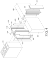
- FIG 4 is an alternative design of the present building assembly 400 suitable for use in the case when a construction beam is present.
- the components of the building assembly 400 in this embodiment are in general same as those in the building assembly 100 depicted in FIG 1 , except the supporting member 410 in this embodiment is structurally different from that in FIG 1 .
- the supporting member in FIG 1 is 110, while in FIG 4 is 410; the elastically deformable gasket in FIG 1 is 130, while in FIG 4 is 430 and so on.
- the supporting member 410 in this embodiment differs from that in FIG 1 in that it further includes a structure for receiving a building beam (e.g., a ceiling beam) therein. As depicted in FIG 4 , the supporting member 410 further includes a rectangular conduit 470 formed on the rear side 4112 of the base 411, in which the rectangular conduit 470 is sized to receive a building beam 450 therein.
- a building beam e.g., a ceiling beam
- the supporting member 410 may be first threadedly secured to the beam 450 by screws 460 or any suitable nut-bolt structure, then the pair of the first sealing members 420 are snap-fitted into the two rails 414 thereby forming two pockets 415 for respectively receiving two wall panels 480 therein. Note that the two pockets 415 are not visible from FIG 4 , as they are occupied by the two wall panels 480.
- the elastically deformable gasket 430 which has a U-shaped in cross section, is snap-fitted into the channel 412, followed by snap-fitting the second sealing member 440 into the U-shaped space of the elastically deformable gasket 430, thereby completing the assemble of two wall panels 480 using the building assembly 400.
- Additional wall panels, ceiling panels or any desired panels may be added next to the two assembled panels 480 using the building assembly 100 described above.
- each of the components discussed above in FIGs 1 to 4 may be manufactured by methods such as casting, stamping, injection molding, extrusion molding and the like, as would be apparent to a skilled artisan; preferably, by extrusion molding. Additionally or alternatively, each of the components discussed above in FIGs 1 to 4 may be milled, sanded or likewise manufactured for a smooth or coarse surface finish. Additionally or alternatively, except for the indicated parts (e.g., the retention tongues, the elastically deformable gasket, and the rib) each of the components discussed above in FIGs 1 to 4 may be made of a plastic, ceramic, metal and other equivalent material, as would be apparent to a skilled artisan.
Landscapes
- Engineering & Computer Science (AREA)
- Architecture (AREA)
- Physics & Mathematics (AREA)
- Electromagnetism (AREA)
- Civil Engineering (AREA)
- Structural Engineering (AREA)
- Building Environments (AREA)
Description
- The present invention relates to a building assembly, particularly to sealed building assembly for use in the construction of chambers, such as germ-free chambers or chambers in which a slight negative or positive pressure is generally present.
- It is known for construction panels to be assembled by a variety of methods and assemblies.
U.S. Publication No. 2015/0376899 illustrates one such method and assembly. However, a need exists for an improved assembling system for constructing chambers suitable for medical use, such as germ-free chambers and chambers having slightly negative pressure therein. - As conventional structures of building assemblies, document
WO 2012/172539 A1 discloses a panel connector including two pairs of wings for holding construction panels (e.g., the panels for building a roof) therebetween. Some of wings further individually incorporate a flexible end made from thermoplastic elastomer to hold the upper surface of the panel, so as to seal the roof against environment factors. - Furthermore, for additional technical background, reference herein is made to document
SG 1020 1808 742 A US 5 228 254 A , wherein publicationSG 1020 1808 742 A - U.S. publication
US 5 228 254 A is directed to a wall construction, which comprises wall panels having a pair of upwardly extending top flanges and a pair of downwardly extending bottom flanges; a longitudinally extending head track having a pair of opening recesses, which are divided by an inner wall carrying resiliently flexible gaskets directed laterally into each of the recesses; and a longitudinally extending floor track disposed substantially below and spaced-apart from the head track. The top flanges of the wall panel are inserted within the recesses straddling the gaskets and forming a seal therewith, while the bottom flanges of the wall panel rest atop ledges on the floor track spaced above the floor, and wherein the gaskets are advantageously formed as dual durometer extrusions. - The present disclosure aims to provide a building assembly that may be easily and economically manufactured, and also easy to assemble, disassemble, or reassemble, further, the connected walls are air-sealed therebetween.
- The object of the present disclosure is to provide a building assembly for use in the construction of chambers, e.g., germ-free chambers or chambers in which a slight negative or positive pressure is generally present. The chambers can be easily assembled, disassembled and/or reassembled in case of an emergency.
- Accordingly, the first aspect of the present disclosure is directed to a building assembly as defined in claim 1, which includes:
- a supporting member comprising a base having a front and rear sides, a channel disposed on the front side of the base at the center thereof, and a pair of rails independently extending parallel and adjacent to the channel at its left and right sides;
- a pair of a first sealing members independently comprising a first base portion having a front and rear sides, and two retention tongues independently extending outwardly from the rear side of the first base portion along the entire longitudinal length thereof;
- an elastically deformable gasket having a U- or V-shaped space in cross section and two flanges independently extending laterally from one edge of the U- or V-shaped space; and
- a second sealing member comprising a second base portion having a front and rear sides, and a rib disposed on the rear side of the second base portion at the center along the longitudinal length thereof;
- the pair of the first sealing members are configured to engage with the supporting member via press-fitting the two retention tongues of each of the first sealing member into each of the rails of the supporting member, thereby creating a pair of pockets (115) independently for receiving each a construction panel therein;
- the elastically deformable gasket is configured to be snap-fitted into the channel of the supporting member to help holding the two construction panels in the pair of pockets (115); and
- the second sealing member is configured to engage with the elastically deformable gasket via press-fitting the rib into the U- or V-shaped space of the elastically deformable gasket so as to hold the elastically deformable gasket (130) in place while creating a tight-seal therebetween.
- According to preferred embodiments of the present disclosure, the second sealing member further includes first and second extensions respectively extending upwardly away from the rear side of the second base portion along the entire longitudinal length thereof.
- According to alternative embodiments of the present disclosure, the supporting member further comprises a rectangular conduit formed on the rear side of the base.
- According to preferred embodiments of the present disclosure, the first sealing member, the elastically deformable gasket and the second sealing member are independently made of a resilient material selected from the group consisting of polypropylene (PP), neoprene, thermoplastic elastomer (TPE), and a combination thereof.
- Examples of the TPE suitable for use in the present disclosure include, but are not limited to, thermoplastic styrene (TPS), thermoplastic vulcanizate (TPV), thermoplastic polyurethane (TPU), thermoplastic polyether ester (TPEE), thermoplastic polyamide (TPA), and the like. Preferably, the first sealing member and the second sealing member are respectively made of TPV, while the elastically deformable gasket is made of PP.
- The disclosure will become more fully understood from the detailed description and the drawings given herein below for illustration only, and thus does not limit the disclosure, wherein:
-
FIG 1 is an exploded view of abuilding assembly 100 in accordance with one preferred embodiment of the present disclosure; -
FIG 2 is a perspective view of thebuilding assembly 100 ofFIG 1 after assembling; -
FIG 3 is a sectional view of an assembly including twowall panels 380 assembled with the aid of the building assembly ofFIG 1 ; and -
FIG 4 is a perspective view of a building assembly 400 for assembling wall panels in the presence of aconstruction beam 450 in according to an alternative embodiment of the present disclosure. - Detailed descriptions and technical contents of the present disclosure are illustrated below in conjunction with the accompanying drawings. However, it is to be understood that the descriptions and the accompanying drawings disclosed herein are merely illustrative and exemplary and not intended to limit the scope of the present disclosure.
- Referring more particularly to
FIGs 1 to 3 , in whichFIG 1 is an exploded view of thepresent building assembly 100;FIG 2 is a perspective view of thebuilding assembly 100 ofFIG 1 after assembling;FIG 3 is a sectional view of an assembly including twowall panels 380 assembled with the aid of the building assembly ofFIG 1 . - The
building assembly 100 in this embodiment comprises a supportingmember 110, a pair of afirst sealing members 120, an elasticallydeformable gasket 130, and asecond sealing member 140. The supportingmember 110 includes in its structure, abase 111 having afront side 1111 and arear side 1112; achannel 112 formed at the center of thefront side 1111 and extends longitudinally alone the entire length of thebase 111; and tworails 114 respectively running parallel adjacent to thechannel 112 at its left and right sides and extends longitudinally along the entire length of thebase 111. - A pair of a
first sealing members 120 are provided for engaging the tworails 114, respectively. Eachsealing member 120 comprises abase portion 121 having a front andrear sides image retention tongues rear side 1212 of thebase portion 121 along the entire longitudinal length thereof. During assembly, eachsealing member 120 is press-fitted or snap-fitted into one of the tworails 120 of the supportingmember 110 to provide a sealed surface, and also creates apocket 115 for subsequently holding a construction panel (not depicted inFIGs 1 and2 ) and the like therein. Specifically, thepocket 115 refers to the space collectively defined by one of therails 114 and one of the channel walls. Accordingly, two construction panels 380 (e.g., wall panels or ceiling panels) may be respectively placed into the twopockets 115 and held against the tworails 114 and the channel 112 (FIG 3 ). - To help holding the two
construction panels 380 in the twopockets 115, an elasticallydeformable gasket 130 may be subsequently press-fitted or snap-fitted into thechannel 112 of the supportingmember 110. The elasticallydeformable gasket 130 has a U- or V-shaped space 132 in cross section, and twoflanges 134 independently extending laterally from one edge of the U- or V-shaped space 132. Once the elasticallydeformable gasket 130 is press-fitted into thechannel 112, the twoflanges 134 will be pressed against the twoconstruction panels 380 respectively held in the two pockets 115 (FIG 3 ). Finally, to complete the assembling, asecond sealing member 140 is press-fitted or snap-fitted into the U- or V-shaped space 132, so as to hold the elasticallydeformable gasket 130 in place while creating a tight-seal therebetween. Structurally, thesecond sealing member 140 comprises asecond base portion 141, arib 142, and twoextensions 143. Thesecond base portion 141 has afront side 1411 and arear side 1412. Therib 142 is formed on therear side 1412 of thesecond base portion 141 at its center and extends along the entire longitudinal length thereof. Additionally or alternatively, therib 142 may be hollow inside. In this embodiment, therib 142 is hollow and rectangular in cross section and is sized to fit into the U- or V-shaped space 132 of the elasticallydeformable gasket 130. Twoextensions 143 independently extend perpendicularly away from therear side 1412 of thesecond base portion 141, and are configured to further hold the elasticallydeformable gasket 130 in place via clinging on to the respective edges of the twoflanges 134. - Note that in the present disclosure, the
first sealing members 120, the elasticallydeformable gasket 130, as well as thesecond sealing member 140 may be independently made of a resilient or elastic material, such as polypropylene (PP), neoprene, thermoplastic elastomer (TPE), and the like. Examples of TPE material suitable for use in the present disclosure include, but are not limited to, thermoplastic styrene (TPS), thermoplastic vulcanizate (TPV), thermoplastic polyurethane (TPU), thermoplastic polyether ester (TPEE), thermoplastic polyamide (TPA) and the like. According to preferred embodiment, thefirst sealing members 120 and thesecond sealing member 140 are respectively made of TPV, while the elasticallydeformable gasket 130 is made of PP. - Reference is now made to
FIG 4 , which is an alternative design of the present building assembly 400 suitable for use in the case when a construction beam is present. The components of the building assembly 400 in this embodiment are in general same as those in thebuilding assembly 100 depicted inFIG 1 , except the supportingmember 410 in this embodiment is structurally different from that inFIG 1 . - As most of the components and pars in the building assembly 400 are same as those in the
building assembly 100, thus the same components and parts are denoted by the common numbering elements. For example, the supporting member inFIG 1 is 110, while inFIG 4 is 410; the elastically deformable gasket inFIG 1 is 130, while inFIG 4 is 430 and so on. - The supporting
member 410 in this embodiment differs from that inFIG 1 in that it further includes a structure for receiving a building beam (e.g., a ceiling beam) therein. As depicted inFIG 4 , the supportingmember 410 further includes arectangular conduit 470 formed on therear side 4112 of thebase 411, in which therectangular conduit 470 is sized to receive abuilding beam 450 therein. - In order to assemble a germ-free chamber or a chamber having a slight negative pressure, the supporting
member 410 may be first threadedly secured to thebeam 450 byscrews 460 or any suitable nut-bolt structure, then the pair of thefirst sealing members 420 are snap-fitted into the tworails 414 thereby forming two pockets 415 for respectively receiving twowall panels 480 therein. Note that the two pockets 415 are not visible fromFIG 4 , as they are occupied by the twowall panels 480. Then, the elasticallydeformable gasket 430, which has a U-shaped in cross section, is snap-fitted into thechannel 412, followed by snap-fitting thesecond sealing member 440 into the U-shaped space of the elasticallydeformable gasket 430, thereby completing the assemble of twowall panels 480 using the building assembly 400. Additional wall panels, ceiling panels or any desired panels (e.g., panels that contain profile of sockets, air conduits and etc.) may be added next to the two assembledpanels 480 using thebuilding assembly 100 described above. - Each of the components discussed above in
FIGs 1 to 4 may be manufactured by methods such as casting, stamping, injection molding, extrusion molding and the like, as would be apparent to a skilled artisan; preferably, by extrusion molding. Additionally or alternatively, each of the components discussed above inFIGs 1 to 4 may be milled, sanded or likewise manufactured for a smooth or coarse surface finish. Additionally or alternatively, except for the indicated parts (e.g., the retention tongues, the elastically deformable gasket, and the rib) each of the components discussed above inFIGs 1 to 4 may be made of a plastic, ceramic, metal and other equivalent material, as would be apparent to a skilled artisan. - It will be understood that the above description of embodiments is given by way of example only and that various modifications may be made by those with ordinary skill in the art. The above specification, examples and data provide a complete description of the structure and use of exemplary embodiments of the invention as defined by the appended claims. Although various embodiments of the invention have been described above with a certain degree of particularity, or with reference to one or more individual embodiments, those with ordinary skill in the art could make numerous alterations to the disclosed embodiments without departing from the scope of protection of the present invention as defined by the appended claims.
Claims (10)
- A building assembly (100) comprising,a supporting member (110) comprising a base (111) having a front and rear sides (1111, 1112), a channel (112) disposed on the front side (1111) of the base (111) at the center thereof, and a pair of rails (114) independently disposed next to the channel (112), in which the channel (112), and the pair of rails (114) independently extends along the entire longitudinal length of the base (111);a pair of a first sealing members (120) independently comprising a first base portion (121) having a front and rear sides (1211, 1212), and two retention tongues (122a, 122b) independently extending outwardly from the rear side (1212) of the first base portion (121) along the entire longitudinal length thereof; an elastically deformable gasket (130) having a U- or V-shaped space (132) in cross section and two flanges (134) independently extending laterally from one edge of the U- or V-shaped space (132); anda second sealing member (140) comprising a second base portion (141) having a front and rear sides (1411, 1412), and a rib (142) disposed on the rear side (1412) of the second base portion (141) at the center along the longitudinal length thereof;wherein,the pair of the first sealing members (120) are configured to engage with the supporting member (110) via press-fitting the two retention tongues (122a, 122b) of each first sealing member (120) into each of the pair of rails (114) of the supporting member (110), thereby creating a pair of pockets (115) independently for receiving each a construction panel therein;the elastically deformable gasket (130) is configured to be snap-fitted into the channel (112) of the supporting member (110) to help holding the two construction panels in the pair of pockets (115); andthe second sealing member (140) is configured to engage with the elastically deformable gasket (130) via press-fitting the rib (142) into the U- or V-shaped space (132) of the elastically deformable gasket (130) so as to hold the elastically deformable gasket (130) in place while creating a tight-seal therebetween.
- The building assembly of claim 1, wherein the second sealing member (140) further comprises a first and second extensions (143) respectively extending upwardly away from the rear side (1412) of the second base portion (141) along the entire longitudinal length thereof.
- The building assembly of claim 1, wherein the first sealing member (120), the elastically deformable gasket (130) and the second sealing member (140) are independently made of a resilient material selected from the group consisting of polypropylene (PP), neoprene, thermoplastic elastomer (TPE), and a combination thereof.
- The building assembly of claim 3, wherein the TPE is selected from the group consisting of thermoplastic styrene (TPS), thermoplastic vulcanizate (TPV), thermoplastic polyurethane (TPU), thermoplastic polyether ester (TPEE), and thermoplastic polyamide (TPA).
- The building assembly of claim 4, wherein the first sealing member (120) and the second sealing member (140) are respectively made of TPV, while the elastically deformable gasket is made of PP.
- The building assembly of claim 1, wherein the supporting member (110) further comprises a rectangular conduit (470) formed on the rear side of the base.
- The building assembly of claim 6, wherein the second sealing member (140) further comprises a first and second extensions (143) respectively extending upwardly away from the rear side (1412) of the second base portion (141) along the entire longitudinal length thereof.
- The building assembly of claim 6, wherein the first sealing member (120), the elastically deformable gasket (130) and the second sealing member (140) are independently made of a resilient material selected from the group consisting of PP, neoprene, and TPE.
- The building assembly of claim 8, wherein the TPE is selected from the group consisting of TPS, TPV, TPU, TPEE, TPA, and a combination thereof.
- The building assembly of claim 9, wherein the first sealing member and the second sealing member are respectively made of TPV, while the elastically deformable gasket is made of PP.
Priority Applications (1)
| Application Number | Priority Date | Filing Date | Title |
|---|---|---|---|
| EP21156147.7A EP4039902B1 (en) | 2021-02-09 | 2021-02-09 | Building assembly |
Applications Claiming Priority (1)
| Application Number | Priority Date | Filing Date | Title |
|---|---|---|---|
| EP21156147.7A EP4039902B1 (en) | 2021-02-09 | 2021-02-09 | Building assembly |
Publications (3)
| Publication Number | Publication Date |
|---|---|
| EP4039902A1 EP4039902A1 (en) | 2022-08-10 |
| EP4039902C0 EP4039902C0 (en) | 2023-09-27 |
| EP4039902B1 true EP4039902B1 (en) | 2023-09-27 |
Family
ID=74661230
Family Applications (1)
| Application Number | Title | Priority Date | Filing Date |
|---|---|---|---|
| EP21156147.7A Active EP4039902B1 (en) | 2021-02-09 | 2021-02-09 | Building assembly |
Country Status (1)
| Country | Link |
|---|---|
| EP (1) | EP4039902B1 (en) |
Family Cites Families (4)
| Publication number | Priority date | Publication date | Assignee | Title |
|---|---|---|---|---|
| US5228254A (en) * | 1991-01-18 | 1993-07-20 | Plascore, Inc. | Wall system |
| IL213495A0 (en) * | 2011-06-12 | 2011-07-31 | Polygal Plastics Ind Ltd | Panel connector with incorporated flexible end |
| US9879420B2 (en) | 2013-02-27 | 2018-01-30 | Maars Holding B.V. | Partition wall system with clamping profile |
| SG10201808742PA (en) * | 2018-10-03 | 2020-05-28 | Gat Sdn Bhd | A system and method for cleanroom partition of wall panel |
-
2021
- 2021-02-09 EP EP21156147.7A patent/EP4039902B1/en active Active
Also Published As
| Publication number | Publication date |
|---|---|
| EP4039902C0 (en) | 2023-09-27 |
| EP4039902A1 (en) | 2022-08-10 |
Similar Documents
| Publication | Publication Date | Title |
|---|---|---|
| US7748176B2 (en) | Flooring systems | |
| US8322102B2 (en) | Wall panel system | |
| US8966839B2 (en) | Window assembly | |
| JPH0415337B2 (en) | ||
| US9091116B2 (en) | Window mull system | |
| US10443234B2 (en) | Curtain wall system and components thereof | |
| US20130320705A1 (en) | Door trim upper structure | |
| MX2011006025A (en) | Concealed suspension ceiling with downward removable panels. | |
| EP3561191B1 (en) | Curtain wall expansion joint | |
| US20060162281A1 (en) | Muntin clip | |
| US20210237844A1 (en) | Buffer zone for interior aircraft features | |
| KR200447585Y1 (en) | Prefabricated panel structure for soundproof wall | |
| CN108138494A (en) | Skylight installation system and component | |
| US11566422B2 (en) | Structural joint and sealing element for panels | |
| TWI757093B (en) | Building assembly | |
| EP4039902A1 (en) | Building assembly | |
| JP7047149B1 (en) | Building assembly | |
| WO2006100542A1 (en) | Glass-walled elevator car | |
| KR101473753B1 (en) | Panel having Tension-clip | |
| ES2597751T3 (en) | Frame or T-joint and method for mounting a frame or T-joint | |
| CN114908865B (en) | Assembly for building | |
| EP2327337A1 (en) | Display case | |
| EP1382924A1 (en) | Sealing device particularly for doors of refrigerators, freezers and the like | |
| ATE183796T1 (en) | ENGAGED ELEMENT FOR PARTITION WALL STRUCTURE AND CORRESPONDING INTERIOR PARTITION WALL | |
| CZ20011844A3 (en) | Building element and building construction |
Legal Events
| Date | Code | Title | Description |
|---|---|---|---|
| PUAI | Public reference made under article 153(3) epc to a published international application that has entered the european phase |
Free format text: ORIGINAL CODE: 0009012 |
|
| STAA | Information on the status of an ep patent application or granted ep patent |
Free format text: STATUS: REQUEST FOR EXAMINATION WAS MADE |
|
| 17P | Request for examination filed |
Effective date: 20210517 |
|
| AK | Designated contracting states |
Kind code of ref document: A1 Designated state(s): AL AT BE BG CH CY CZ DE DK EE ES FI FR GB GR HR HU IE IS IT LI LT LU LV MC MK MT NL NO PL PT RO RS SE SI SK SM TR |
|
| RBV | Designated contracting states (corrected) |
Designated state(s): AL AT BE BG CH CY CZ DE DK EE ES FI FR GB GR HR HU IE IS IT LI LT LU LV MC MK MT NL NO PL PT RO RS SE SI SK SM TR |
|
| GRAP | Despatch of communication of intention to grant a patent |
Free format text: ORIGINAL CODE: EPIDOSNIGR1 |
|
| STAA | Information on the status of an ep patent application or granted ep patent |
Free format text: STATUS: GRANT OF PATENT IS INTENDED |
|
| INTG | Intention to grant announced |
Effective date: 20230406 |
|
| GRAS | Grant fee paid |
Free format text: ORIGINAL CODE: EPIDOSNIGR3 |
|
| GRAA | (expected) grant |
Free format text: ORIGINAL CODE: 0009210 |
|
| STAA | Information on the status of an ep patent application or granted ep patent |
Free format text: STATUS: THE PATENT HAS BEEN GRANTED |
|
| RIN1 | Information on inventor provided before grant (corrected) |
Inventor name: HUANG, PEI-YI Inventor name: HSING, YU-TUNG Inventor name: YAI, YU-YING Inventor name: CHEN, JUI-PING Inventor name: LIU, TZU-WEI Inventor name: HUANG, CHIAN-CHI |
|
| AK | Designated contracting states |
Kind code of ref document: B1 Designated state(s): AL AT BE BG CH CY CZ DE DK EE ES FI FR GB GR HR HU IE IS IT LI LT LU LV MC MK MT NL NO PL PT RO RS SE SI SK SM TR |
|
| REG | Reference to a national code |
Ref country code: GB Ref legal event code: FG4D |
|
| REG | Reference to a national code |
Ref country code: CH Ref legal event code: EP |
|
| REG | Reference to a national code |
Ref country code: DE Ref legal event code: R096 Ref document number: 602021005336 Country of ref document: DE |
|
| REG | Reference to a national code |
Ref country code: IE Ref legal event code: FG4D |
|
| U01 | Request for unitary effect filed |
Effective date: 20231027 |
|
| U07 | Unitary effect registered |
Designated state(s): AT BE BG DE DK EE FI FR IT LT LU LV MT NL PT SE SI Effective date: 20231106 |
|
| PG25 | Lapsed in a contracting state [announced via postgrant information from national office to epo] |
Ref country code: GR Free format text: LAPSE BECAUSE OF FAILURE TO SUBMIT A TRANSLATION OF THE DESCRIPTION OR TO PAY THE FEE WITHIN THE PRESCRIBED TIME-LIMIT Effective date: 20231228 |
|
| PG25 | Lapsed in a contracting state [announced via postgrant information from national office to epo] |
Ref country code: RS Free format text: LAPSE BECAUSE OF FAILURE TO SUBMIT A TRANSLATION OF THE DESCRIPTION OR TO PAY THE FEE WITHIN THE PRESCRIBED TIME-LIMIT Effective date: 20230927 Ref country code: NO Free format text: LAPSE BECAUSE OF FAILURE TO SUBMIT A TRANSLATION OF THE DESCRIPTION OR TO PAY THE FEE WITHIN THE PRESCRIBED TIME-LIMIT Effective date: 20231227 Ref country code: HR Free format text: LAPSE BECAUSE OF FAILURE TO SUBMIT A TRANSLATION OF THE DESCRIPTION OR TO PAY THE FEE WITHIN THE PRESCRIBED TIME-LIMIT Effective date: 20230927 Ref country code: GR Free format text: LAPSE BECAUSE OF FAILURE TO SUBMIT A TRANSLATION OF THE DESCRIPTION OR TO PAY THE FEE WITHIN THE PRESCRIBED TIME-LIMIT Effective date: 20231228 |
|
| U20 | Renewal fee for the european patent with unitary effect paid |
Year of fee payment: 4 Effective date: 20240226 |
|
| PG25 | Lapsed in a contracting state [announced via postgrant information from national office to epo] |
Ref country code: IS Free format text: LAPSE BECAUSE OF FAILURE TO SUBMIT A TRANSLATION OF THE DESCRIPTION OR TO PAY THE FEE WITHIN THE PRESCRIBED TIME-LIMIT Effective date: 20240127 |
|
| PG25 | Lapsed in a contracting state [announced via postgrant information from national office to epo] |
Ref country code: ES Free format text: LAPSE BECAUSE OF FAILURE TO SUBMIT A TRANSLATION OF THE DESCRIPTION OR TO PAY THE FEE WITHIN THE PRESCRIBED TIME-LIMIT Effective date: 20230927 |
|
| PG25 | Lapsed in a contracting state [announced via postgrant information from national office to epo] |
Ref country code: SM Free format text: LAPSE BECAUSE OF FAILURE TO SUBMIT A TRANSLATION OF THE DESCRIPTION OR TO PAY THE FEE WITHIN THE PRESCRIBED TIME-LIMIT Effective date: 20230927 Ref country code: RO Free format text: LAPSE BECAUSE OF FAILURE TO SUBMIT A TRANSLATION OF THE DESCRIPTION OR TO PAY THE FEE WITHIN THE PRESCRIBED TIME-LIMIT Effective date: 20230927 Ref country code: IS Free format text: LAPSE BECAUSE OF FAILURE TO SUBMIT A TRANSLATION OF THE DESCRIPTION OR TO PAY THE FEE WITHIN THE PRESCRIBED TIME-LIMIT Effective date: 20240127 Ref country code: ES Free format text: LAPSE BECAUSE OF FAILURE TO SUBMIT A TRANSLATION OF THE DESCRIPTION OR TO PAY THE FEE WITHIN THE PRESCRIBED TIME-LIMIT Effective date: 20230927 Ref country code: CZ Free format text: LAPSE BECAUSE OF FAILURE TO SUBMIT A TRANSLATION OF THE DESCRIPTION OR TO PAY THE FEE WITHIN THE PRESCRIBED TIME-LIMIT Effective date: 20230927 Ref country code: SK Free format text: LAPSE BECAUSE OF FAILURE TO SUBMIT A TRANSLATION OF THE DESCRIPTION OR TO PAY THE FEE WITHIN THE PRESCRIBED TIME-LIMIT Effective date: 20230927 |
|
| PG25 | Lapsed in a contracting state [announced via postgrant information from national office to epo] |
Ref country code: PL Free format text: LAPSE BECAUSE OF FAILURE TO SUBMIT A TRANSLATION OF THE DESCRIPTION OR TO PAY THE FEE WITHIN THE PRESCRIBED TIME-LIMIT Effective date: 20230927 |
|
| REG | Reference to a national code |
Ref country code: DE Ref legal event code: R097 Ref document number: 602021005336 Country of ref document: DE |
|
| PLBE | No opposition filed within time limit |
Free format text: ORIGINAL CODE: 0009261 |
|
| STAA | Information on the status of an ep patent application or granted ep patent |
Free format text: STATUS: NO OPPOSITION FILED WITHIN TIME LIMIT |
|
| 26N | No opposition filed |
Effective date: 20240628 |
|
| PG25 | Lapsed in a contracting state [announced via postgrant information from national office to epo] |
Ref country code: MC Free format text: LAPSE BECAUSE OF FAILURE TO SUBMIT A TRANSLATION OF THE DESCRIPTION OR TO PAY THE FEE WITHIN THE PRESCRIBED TIME-LIMIT Effective date: 20230927 |
|
| REG | Reference to a national code |
Ref country code: CH Ref legal event code: PL |
|
| PG25 | Lapsed in a contracting state [announced via postgrant information from national office to epo] |
Ref country code: CH Free format text: LAPSE BECAUSE OF NON-PAYMENT OF DUE FEES Effective date: 20240229 |
|
| PG25 | Lapsed in a contracting state [announced via postgrant information from national office to epo] |
Ref country code: CH Free format text: LAPSE BECAUSE OF NON-PAYMENT OF DUE FEES Effective date: 20240229 |
|
| PG25 | Lapsed in a contracting state [announced via postgrant information from national office to epo] |
Ref country code: IE Free format text: LAPSE BECAUSE OF NON-PAYMENT OF DUE FEES Effective date: 20240209 |
|
| PG25 | Lapsed in a contracting state [announced via postgrant information from national office to epo] |
Ref country code: IE Free format text: LAPSE BECAUSE OF NON-PAYMENT OF DUE FEES Effective date: 20240209 |
|
| U20 | Renewal fee for the european patent with unitary effect paid |
Year of fee payment: 5 Effective date: 20250226 |
|
| PG25 | Lapsed in a contracting state [announced via postgrant information from national office to epo] |
Ref country code: CY Free format text: LAPSE BECAUSE OF FAILURE TO SUBMIT A TRANSLATION OF THE DESCRIPTION OR TO PAY THE FEE WITHIN THE PRESCRIBED TIME-LIMIT; INVALID AB INITIO Effective date: 20210209 |
|
| PG25 | Lapsed in a contracting state [announced via postgrant information from national office to epo] |
Ref country code: HU Free format text: LAPSE BECAUSE OF FAILURE TO SUBMIT A TRANSLATION OF THE DESCRIPTION OR TO PAY THE FEE WITHIN THE PRESCRIBED TIME-LIMIT; INVALID AB INITIO Effective date: 20210209 |
|
| GBPC | Gb: european patent ceased through non-payment of renewal fee |
Effective date: 20250209 |
|
| PG25 | Lapsed in a contracting state [announced via postgrant information from national office to epo] |
Ref country code: TR Free format text: LAPSE BECAUSE OF FAILURE TO SUBMIT A TRANSLATION OF THE DESCRIPTION OR TO PAY THE FEE WITHIN THE PRESCRIBED TIME-LIMIT Effective date: 20230927 |
|
| PG25 | Lapsed in a contracting state [announced via postgrant information from national office to epo] |
Ref country code: GB Free format text: LAPSE BECAUSE OF NON-PAYMENT OF DUE FEES Effective date: 20250209 |