EP4039769A1 - Thermal storage device - Google Patents
Thermal storage device Download PDFInfo
- Publication number
- EP4039769A1 EP4039769A1 EP19948001.3A EP19948001A EP4039769A1 EP 4039769 A1 EP4039769 A1 EP 4039769A1 EP 19948001 A EP19948001 A EP 19948001A EP 4039769 A1 EP4039769 A1 EP 4039769A1
- Authority
- EP
- European Patent Office
- Prior art keywords
- group
- heat
- heat storage
- general formula
- storage material
- Prior art date
- Legal status (The legal status is an assumption and is not a legal conclusion. Google has not performed a legal analysis and makes no representation as to the accuracy of the status listed.)
- Granted
Links
Images

Classifications
-
- F—MECHANICAL ENGINEERING; LIGHTING; HEATING; WEAPONS; BLASTING
- F28—HEAT EXCHANGE IN GENERAL
- F28D—HEAT-EXCHANGE APPARATUS, NOT PROVIDED FOR IN ANOTHER SUBCLASS, IN WHICH THE HEAT-EXCHANGE MEDIA DO NOT COME INTO DIRECT CONTACT
- F28D20/00—Heat storage plants or apparatus in general; Regenerative heat-exchange apparatus not covered by groups F28D17/00 or F28D19/00
-
- C—CHEMISTRY; METALLURGY
- C09—DYES; PAINTS; POLISHES; NATURAL RESINS; ADHESIVES; COMPOSITIONS NOT OTHERWISE PROVIDED FOR; APPLICATIONS OF MATERIALS NOT OTHERWISE PROVIDED FOR
- C09K—MATERIALS FOR MISCELLANEOUS APPLICATIONS, NOT PROVIDED FOR ELSEWHERE
- C09K5/00—Heat-transfer, heat-exchange or heat-storage materials, e.g. refrigerants; Materials for the production of heat or cold by chemical reactions other than by combustion
- C09K5/02—Materials undergoing a change of physical state when used
- C09K5/06—Materials undergoing a change of physical state when used the change of state being from liquid to solid or vice versa
- C09K5/063—Materials absorbing or liberating heat during crystallisation; Heat storage materials
-
- C—CHEMISTRY; METALLURGY
- C08—ORGANIC MACROMOLECULAR COMPOUNDS; THEIR PREPARATION OR CHEMICAL WORKING-UP; COMPOSITIONS BASED THEREON
- C08F—MACROMOLECULAR COMPOUNDS OBTAINED BY REACTIONS ONLY INVOLVING CARBON-TO-CARBON UNSATURATED BONDS
- C08F220/00—Copolymers of compounds having one or more unsaturated aliphatic radicals, each having only one carbon-to-carbon double bond, and only one being terminated by only one carboxyl radical or a salt, anhydride ester, amide, imide or nitrile thereof
- C08F220/02—Monocarboxylic acids having less than ten carbon atoms; Derivatives thereof
- C08F220/52—Amides or imides
- C08F220/54—Amides, e.g. N,N-dimethylacrylamide or N-isopropylacrylamide
- C08F220/56—Acrylamide; Methacrylamide
-
- C—CHEMISTRY; METALLURGY
- C08—ORGANIC MACROMOLECULAR COMPOUNDS; THEIR PREPARATION OR CHEMICAL WORKING-UP; COMPOSITIONS BASED THEREON
- C08F—MACROMOLECULAR COMPOUNDS OBTAINED BY REACTIONS ONLY INVOLVING CARBON-TO-CARBON UNSATURATED BONDS
- C08F220/00—Copolymers of compounds having one or more unsaturated aliphatic radicals, each having only one carbon-to-carbon double bond, and only one being terminated by only one carboxyl radical or a salt, anhydride ester, amide, imide or nitrile thereof
- C08F220/02—Monocarboxylic acids having less than ten carbon atoms; Derivatives thereof
- C08F220/52—Amides or imides
- C08F220/54—Amides, e.g. N,N-dimethylacrylamide or N-isopropylacrylamide
- C08F220/58—Amides, e.g. N,N-dimethylacrylamide or N-isopropylacrylamide containing oxygen in addition to the carbonamido oxygen, e.g. N-methylolacrylamide, N-(meth)acryloylmorpholine
-
- C—CHEMISTRY; METALLURGY
- C09—DYES; PAINTS; POLISHES; NATURAL RESINS; ADHESIVES; COMPOSITIONS NOT OTHERWISE PROVIDED FOR; APPLICATIONS OF MATERIALS NOT OTHERWISE PROVIDED FOR
- C09K—MATERIALS FOR MISCELLANEOUS APPLICATIONS, NOT PROVIDED FOR ELSEWHERE
- C09K5/00—Heat-transfer, heat-exchange or heat-storage materials, e.g. refrigerants; Materials for the production of heat or cold by chemical reactions other than by combustion
- C09K5/08—Materials not undergoing a change of physical state when used
- C09K5/10—Liquid materials
-
- C—CHEMISTRY; METALLURGY
- C09—DYES; PAINTS; POLISHES; NATURAL RESINS; ADHESIVES; COMPOSITIONS NOT OTHERWISE PROVIDED FOR; APPLICATIONS OF MATERIALS NOT OTHERWISE PROVIDED FOR
- C09K—MATERIALS FOR MISCELLANEOUS APPLICATIONS, NOT PROVIDED FOR ELSEWHERE
- C09K5/00—Heat-transfer, heat-exchange or heat-storage materials, e.g. refrigerants; Materials for the production of heat or cold by chemical reactions other than by combustion
- C09K5/08—Materials not undergoing a change of physical state when used
- C09K5/14—Solid materials, e.g. powdery or granular
-
- F—MECHANICAL ENGINEERING; LIGHTING; HEATING; WEAPONS; BLASTING
- F28—HEAT EXCHANGE IN GENERAL
- F28D—HEAT-EXCHANGE APPARATUS, NOT PROVIDED FOR IN ANOTHER SUBCLASS, IN WHICH THE HEAT-EXCHANGE MEDIA DO NOT COME INTO DIRECT CONTACT
- F28D20/00—Heat storage plants or apparatus in general; Regenerative heat-exchange apparatus not covered by groups F28D17/00 or F28D19/00
- F28D20/003—Heat storage plants or apparatus in general; Regenerative heat-exchange apparatus not covered by groups F28D17/00 or F28D19/00 using thermochemical reactions
-
- F—MECHANICAL ENGINEERING; LIGHTING; HEATING; WEAPONS; BLASTING
- F28—HEAT EXCHANGE IN GENERAL
- F28D—HEAT-EXCHANGE APPARATUS, NOT PROVIDED FOR IN ANOTHER SUBCLASS, IN WHICH THE HEAT-EXCHANGE MEDIA DO NOT COME INTO DIRECT CONTACT
- F28D20/00—Heat storage plants or apparatus in general; Regenerative heat-exchange apparatus not covered by groups F28D17/00 or F28D19/00
- F28D20/02—Heat storage plants or apparatus in general; Regenerative heat-exchange apparatus not covered by groups F28D17/00 or F28D19/00 using latent heat
- F28D20/021—Heat storage plants or apparatus in general; Regenerative heat-exchange apparatus not covered by groups F28D17/00 or F28D19/00 using latent heat the latent heat storage material and the heat-exchanging means being enclosed in one container
-
- C—CHEMISTRY; METALLURGY
- C08—ORGANIC MACROMOLECULAR COMPOUNDS; THEIR PREPARATION OR CHEMICAL WORKING-UP; COMPOSITIONS BASED THEREON
- C08F—MACROMOLECULAR COMPOUNDS OBTAINED BY REACTIONS ONLY INVOLVING CARBON-TO-CARBON UNSATURATED BONDS
- C08F2800/00—Copolymer characterised by the proportions of the comonomers expressed
- C08F2800/10—Copolymer characterised by the proportions of the comonomers expressed as molar percentages
-
- Y—GENERAL TAGGING OF NEW TECHNOLOGICAL DEVELOPMENTS; GENERAL TAGGING OF CROSS-SECTIONAL TECHNOLOGIES SPANNING OVER SEVERAL SECTIONS OF THE IPC; TECHNICAL SUBJECTS COVERED BY FORMER USPC CROSS-REFERENCE ART COLLECTIONS [XRACs] AND DIGESTS
- Y02—TECHNOLOGIES OR APPLICATIONS FOR MITIGATION OR ADAPTATION AGAINST CLIMATE CHANGE
- Y02E—REDUCTION OF GREENHOUSE GAS [GHG] EMISSIONS, RELATED TO ENERGY GENERATION, TRANSMISSION OR DISTRIBUTION
- Y02E60/00—Enabling technologies; Technologies with a potential or indirect contribution to GHG emissions mitigation
- Y02E60/14—Thermal energy storage
Definitions
- the present invention relates to a heat storage apparatus including a heat storage material.
- heat storage apparatuses each having a heat storage material have been known.
- facilities having heat sources such as homes, offices, factories, or waste processing facilities
- most of low-temperature exhaust heat of approximately 120 °C or less is discharged without being used.
- it is required to use a heat storage material that stores low-temperature exhaust heat at a high density.
- the heat storage material should have a melting point of 100 °C or less.
- inorganic heat storage materials such as barium hydroxide octahydrate having a melting point of 78 °C and magnesium nitrate hexahydrate having a melting point of 89 °C, is present.
- the inorganic hydrated salt has problems. That is, barium hydroxide octahydrate is specified as a deleterious substance, and magnesium nitrate hexahydrate corrodes metal. Therefore, these inorganic heat storage materials are not put to practical use.
- organic heat storage materials paraffin, fatty acids, sugar alcohol, etc., are present. However, paraffin, fatty acids, sugar alcohol, and other substances are not put to practical use because they have a small heat storage density because of the heat of fusion.
- Patent Literature 1 discloses a heat storage material in which a mixture of a guest substance and water that is a host substance is cooled to produce a hydrate. Furthermore, in recent years, heat storage materials including hydrogel have been known. A heat storage material using hydrogel maintains a non-fluid property even in a temperature range above a phase transition temperature, and can stably maintain a non-fluid property even when being repeatedly cooled and heated such that its temperature varies to a lower temperature and a higher temperature through the phase transition temperature.
- Patent Literature 2 discloses a first gelled material, a second gelled material, and an inorganic or aqueous heat storage material that is held between the first gelled material and the second gelled material.
- the first gelled material is produced by crosslinking at least one polymer selected from polyacrylamide derivatives, polyvinyl alcohol, sodium polyacrylate, and sodium polymethacrylate.
- the second gelled material is polysaccharides, agar, or gelatin.
- Patent Literature 3 discloses a heat storage device including a heat exchanger that causes heat exchange to be performed between a heating fluid and a heat storage material to heat the heat storage material and store heat in the heat storage material.
- Patent Literature 1 and Patent Literature 2 have a small heat storage density.
- a thermal storage tank is made larger, and as a result, a heat storage apparatus including the thermal storage tank is also made larger.
- the thermal storage unit disclosed in Patent Literature 3 cannot be applied to a cooling apparatus, since a heat storage material cannot store cooling energy.
- the present invention is applied to solve the above problems, and the object underlying the invention is to provide a heat storage apparatus that can be used in a cooling apparatus and is not made larger, as compared with existing heat source apparatuses.
- a heat storage apparatus of an embodiment of the present invention includes: a container sealed, with a heat storage material encased in the container, the heat storage material including a thermosensitive polymer gel including a thermosensitive polymer and a solvent selected from the group consisting of water, organic solvents, and compounds of water or organic solvents; and a heat exchanger housed in the container, and configured to cause heat exchange to be performed between the heat storage material and a heating/cooling fluid to heat or cool the heat storage material, and store heating energy or cooling energy in the heat storage material, the heat exchanger being configured to cause heat exchange to be performed between the heat storage material and a heat utilization fluid to receive heat from the heat storage material and to transfer heat from the heat storage material.
- the heat storage material makes a reversible hydrophilic-hydrophobic transition at a lower critical solution temperature, and the solvent included in the thermosensitive polymer gel is kept in a liquid state in a process of hydrophilic-hydrophobic transition.
- the heat storage material makes reversible hydrophilic-hydrophobic transition at a lower critical solution temperature, and the solvent included in the thermosensitive polymer gel is kept in a liquid state in the process of hydrophilic-hydrophobic transition.
- a heat storage apparatus can store cooling energy in the heat storage material. The heat storage apparatus can thus be used in a cooling apparatus and is not made larger.
- FIG. 1 is a circuit diagram of a heat storage system 2 according to Embodiment 1.
- the heat storage system 2 uses a heat storage apparatus 1 to perform air cooling or air heating at a heat transfer terminal 23.
- the heat storage system 2 includes a heat source 3, a heating/cooling pump 52, a circulation pump 22, the heat storage apparatus 1, a heating/cooling fluid, and a heat utilization fluid.
- a lower joint 15 of a heating/cooling pipe 13 is connected to the heat source 3 by an inlet pipe 50 via the heating/cooling pump 52.
- the heat source 3 is connected to an upper joint 15 of the heating/cooling pipe 13 by an outlet pipe 51.
- a heat source circuit 31 is provided, and the heating/cooling fluid circulates in the heat source circuit 31.
- the heat source 3 generates heat, and is, for example, an electric heater or a vapor compression heat pump that is driven by power.
- the heat source 3 heats the heating/cooling fluid that flows thereinto through the inlet pipe 50.
- the heating/cooling pump 52 is used to transfer the heating/cooling fluid.
- the heating/cooling pump 52 transfers, to the heat source 3, the heating/cooling fluid that flows through the inlet pipe 50, causes the heating/cooling fluid that flows out of the heat source 3 to flow through the outlet pipe 51, and transfers the heating/cooling fluid to the heating/cooling pipe 13.
- the circulation pump 22 is used to transfer the heating/cooling fluid.
- the circulation pump 22 transfers, to the heat storage apparatus 1, the heat utilization fluid that flows through a return pipe 20, causes the heat utilization fluid that flows out of the heat storage apparatus 1 to flow through a feed pipe 21, and transfers the heat utilization fluid to the heat transfer terminal 23.
- the heating/cooling fluid is, for example, water, an antifreeze, such as ethylene glycol or propylene glycol, or refrigerant, such as HFC or CO 2 .
- a lower joint 15 of a heat utilization pipe 14 is connected to the heat transfer terminal 23 by the return pipe 20 via the circulation pump 22.
- An upper joint 15 of the heat utilization pipe 14 is connected to the heat transfer terminal 23, which is a heat utilization terminal, by the feed pipe 21.
- a utilization circuit 32 is provided, and the heat utilization fluid circulates in the utilization circuit 32.
- the heat utilization fluid is, for example, water or an antifreeze, such as ethylene glycol or propylene glycol.
- the heat transfer terminal 23 is, for example, a floor heating panel, a fan coil unit, or a hot water radiator panel.
- the heat transfer terminal 23 is an example of a heat utilization terminal, and cooling energy or heating energy transferred from the heat utilization fluid in the heat transfer terminal 23 is utilized in, for example, air cooling or air heating.
- FIG. 2 is a sectional view of a heat storage apparatus 1 according to Embodiment 1.
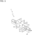
- FIG. 3 is a perspective view of the heat storage apparatus 1 according to Embodiment 1.
- the heat storage apparatus 1 includes a container 10 and a heat exchanger 11.
- the container 10 is, for example, substantially cuboid, is made of stainless steel (SUS), and has a thickness of 1 mm.
- the container 10 is filled with a heat storage material 60.
- the container 10 houses the heat exchanger 11.
- a plurality of openings are provided into which the heating/cooling pipe 13 and the heat utilization pipe 14 of the heat exchanger 11 are inserted.
- the heat exchanger 11 is, for example, a fin-and-tube heat exchanger, and includes the heating/cooling pipe 13, the heat utilization pipe 14, and a plurality of fins 12.
- the heating/cooling pipe 13 is, for example, a cylindrical or flat tube made of metal such as SUS or Cu. In the heating/cooling pipe 13, a heating/cooling fluid to heat or cool the heat storage material 60 flows.
- the heating/cooling pipe 13 is inserted into the openings formed in the upper surface and the lower surface of the container 10, and extends from the inside of the container 10 to the outside thereof.
- joints 15 are provided (see FIG. 1 ).
- the type of the joints 15 can be appropriately changed depending on the configuration of the heat storage system 2 including the heat storage apparatus 1.
- quick fastener joints or Swagelok joints can be used as the joints 15. Since the joints 15 are provided at the heating/cooling pipe 13, it is possible to easily connect the heat storage apparatus 1 to the inlet pipe 50 and the outlet pipe 51.
- the heat utilization pipe 14 is, for example, a cylindrical or flat pipe made of metal such as SUS or Cu.
- a heat utilization fluid to receive heat from the heat storage material 60 flows.
- the heat utilization pipe 14 is inserted into openings formed in an upper surface and a lower surface of the container 10, and extends from the inside of the container 10 to the outside thereof.
- joints 15 are provided (see FIG. 1 ).
- the type of the joints 15 can be appropriately changed depending on the configuration of the heat storage system 2 including the heat storage apparatus 1.
- quick fastener joints or Swagelok joints can be used as the joints 15. Since the joints 15 are provided at the heat utilization pipe 14, it is possible to easily connect the heat storage apparatus 1 to the return pipe 20 and the feed pipe 21.
- the fins 12 are, for example, plate fins made of metal such as SUS or Al, and arranged substantially parallel to each other. In the fins 12, openings (not illustrated) are provided. The heating/cooling pipe 13 and the heat utilization pipe 14 are inserted into the openings of the fins 12 arranged substantially parallel to each other.
- the heat exchanger 11 causes heat exchange to be performed between the heating/cooling fluid and the heat storage material 60, thereby heating or cooling the heat storage material 60 to store heat in the heat storage material 60, and also causes heat exchange to be performed between the heat utilization fluid and the heat storage material 60, thereby receiving heat from the heat storage material 60 and causing the heat storage material 60 to transfer heat therefrom.
- the heat exchanger 11 may have any configuration as long as the heat exchanger 11 can cause the heat storage material 60 to be heated and to transfer heat.
- the shape and material of the heat exchanger 11 can be changed appropriately.
- the heat exchanger 11 may be configured such that the fins 12 are not provided and the heating/cooling pipe 13 and the heat utilization pipe 14 are arranged at a high density.
- the heat exchanger 11 may be configured such that the following layers are stacked together: a layer through which the heating/cooling fluid flows; a layer through which the heat utilization fluid flows; and a layer filled with the heat storage material 60.
- the heat storage material 60 has a thermosensitive polymer gel including a thermosensitive polymer 61 and a solvent selected from the group consisting of water 62, an organic solvent, and a compound of water 62 or organic solvents.
- the heat storage material 60 transfers heat or receives heat when the thermosensitive polymer 61 adsorbs or desorbs water 62.
- the density of the thermosensitive polymer 61 is higher than that of water 62.
- the density of thermosensitive polymer 61 containing hydrophobized bubbles is lower than that of water 62.
- the heat storage material 60 makes a reversible hydrophilic-hydrophobic transition at a lower critical solution temperature, and the solvent included in the thermosensitive polymer gel is kept in a liquid state during the process of hydrophilic-hydrophobic transition.
- the lower critical solution temperature is abbreviated as a LCST.
- the thermosensitive polymer 61 exhibits a hydrophilic property at a temperature below the LCST, and exhibits a hydrophobic property at a temperature above the LCST. In other words, the thermosensitive polymer 61 makes a reversible hydrophilic-hydrophobic transition at the lower critical solution temperature.
- thermosensitive polymer 61 the following can be used: partially acetylated polyvinyl alcohol; polyvinyl methyl ether; methyl cellulose; polyethylene oxide; polyvinyl methyl oxazolidinone; poly N-ethyl acrylamide; poly N-ethyl methacrylamide; poly N-n-propyl acrylamide; poly N-n-propyl methacrylamide; poly N-isopropyl acrylamide; poly N-isopropyl methacrylamide; poly N-cyclopropyl acrylamide; poly N-cyclopropyl methacrylamide; poly N-methyl-N-ethyl acrylamide; poly N,N-diethyl acrylamide, poly N-methyl-N-isopropyl acrylamide; poly N-methyl-N-n-propyl acrylamide; poly N-acryloylpyrrolidine; poly-N-acryloylpiperidine; poly N-2-ethoxyethyl acrylamide
- the thermosensitive polymer 61 has a crosslinked structure, and has, at its molecular end, at least one functional group selected from the group consisting of a hydroxy group, a sulfonate group, an oxysulfonate group, a phosphate group, and an oxyphosphate group.
- the molar ratio between repeating units that form the thermosensitive polymer 61, the functional group, and the unit of the crosslinked structure falls within the range of 99:0.5:0.5 to 70:20:10.
- it is preferable that the molar ratio between the repeating units that form the thermosensitive polymer, the functional group, and the unit of the crosslinked structure fall within the range of 98:1:1 to 77:18:5.
- the percentage of the repeating units In the case where the percentage of the repeating units is too high, the heat storage density decreases.
- the case where the percentage of the repeating units is high corresponds to the case where when the total molecular weight of the repeating units, the functional group and the unit of the crosslinked structure is 100 mol%, the percentage of the repeating units exceeds 99 mol%.
- the percentage of the repeating units is too low, the LCST is not exhibited.
- the case where the percentage of the repeating units is low corresponds to the case where when, for example, the total amount of the repeating unit, the functional group and the unit of the crosslinked structure is 100 mol%, the percentage of the repeating unit is below 70 mol%.
- the unit of the crosslinked structure is introduced by applying a cross-linker in the process of producing the thermosensitive polymer 61, such as partially acetylated polyvinyl alcohol or polyvinyl methyl ether described above.
- the cross-linker may be referred to as a cross-linkable monomer.
- cross-linker for example, the following are present: N,N'-methylenebisacrylamide; N,N'-diallylacrylamide; N,N'-diacryloylimide, N,N'-dimethacryloylimide; triallylformal; diallyl naphthalate; ethylene glycol diacrylate; ethylene glycol dimethacrylate; various polyethylene glycol di(meth)acrylates; propylene glycol diacrylate; propylene glycol dimethacrylate; various polypropylene glycol di(meth)acrylates; 1,3-butylene glycol diacrylate; 1,3-butylene glycol dimethacrylate; 1,4-butylene glycol dimethacrylate; various butylene glycol di(meth)acrylates; glycerol dimethacrylate; neopentyl glycol dimethacrylate; trimethylolpropane triacrylate; trimethylolpropane trimethacrylate; tetramethylo
- the organic solvent is selected from polar organic solvents, and preferably, should be selected from the group consisting of alcohols, such as methanol, ethanol, propanol, isopropanol, isopentanol, and 2-methoxyethanol; ketones, such as acetone, methyl ethyl ketone, methyl n-propyl ketone, methyl isopropyl ketone, and methyl isoamyl ketone; ethers, such as ethylene glycol monobutyl ether, and propylene glycol monomethyl ether; methyl acetate; ethyl acetate; propyl acetate; n-butyl acetate; chloroform; acetonitrile; glycerol; dimethyl sulfoxide; N,N-dimethylformamide; tetrahydrofuran; pyridine; 1,4-dioxane; dimethylacetamide; N-methylpyrrolidone; propylene
- the organic solvent is selected from nonpolar organic solvents, and preferably, should be selected from the group consisting of benzene, chlorobenzene; o-dichlorobenzene; toluene; o-xylene; dichloromethane; 1,1,2-trichlorotrifluoroethane; pentane; cyclopentane; hexane; cyclohexane; heptane; isooctane; diethyl ether; petroleum ether; pyridine; carbon tetrachloride; fatty acids; fatty acid esters; and mixtures thereof.
- the organic solvent is selected from oils, and preferably, should be selected from the group consisting of vegetable oils, essential oils, petrochemical oils, synthetic oils, and mixtures thereof.
- the organic solvent may be referred to as a lipophilic solvent.
- the organic solvent may be a mixture of at least one kind of polar organic solvent or nonpolar organic solvent and at least one kind of oil.
- the thermosensitive polymer gel includes a building block expressed by the following general Formula (1); (where R 1 is a hydrogen atom or a methyl group, R 2 is an N-3-isopropoxypropyl group or an N-1-methoxymethylpropyl group, X is an atom in a covalent bond or at least one functional group selected from the group consisting of a hydroxy group, a sulfonate group, an oxysulfonate group, a phosphate group, and an oxyphosphate group, and ⁇ is an atom in a covalent bond), or includes a building block expressed by the following general Formula (2); (where R 1 is a hydrogen atom or a methyl group, R 2 is an N-3-isopropoxypropyl group or an N-1-methoxymethylpropyl group, X is an atom in a covalent bond or at least one functional group selected from the group consisting of a hydroxy group, a sulfonate group, an oxysulfonate
- thermosensitive polymer gel has a crosslinked structure in which the atom in the covalent bond of the building block expressed by general Formula (1) or general Formula (2) is bonded to the atom in the covalent bond of the building block expressed by general Formula (3).
- the molar ratio between the building block expressed by general Formula (1) or general Formula (2), X which is the functional group, and the building block expressed by general Formula (3) is 99:0.5:0.5 to 70:23:7.
- the molar ratio between the building block expressed by general Formula (1) or general Formula (2), X which is the functional group, and the building block expressed by general Formula (3) is 99:0.5:0.5 to 70:23:7, and preferably should be 98:1:1 to 77:18:5. In the case where the percentage of the building block expressed by general Formula (1) or general Formula (2) is too high, the heat storage density is low.
- the case where the percentage of the building block expressed by general Formula (1) or general Formula (2) is high corresponds to the case where the percentage of the building block expressed by general Formula (1) or general Formula (2) exceeds 99 mol% when, for example, the total molecular weight of the building block expressed by general Formula (1) or general Formula (2), X which is the functional group, and the building block expressed by general Formula (3) is 100 mol%.
- the percentage of the building block expressed by general Formula (1) or general Formula (2) is too low, an LCST is not exhibited.
- the case where the percentage of the building block expressed by general Formula (1) or general Formula (2) is low corresponds to the case where the percentage of the building block expressed by general Formula (1) or general Formula (2) is below 70 mol% when, for example, the total molecular weight of the building block expressed by general Formula (1) or general Formula (2), X which is the functional group, and the building block expressed by general Formula (3) is 100 mol%.
- the molar ratio between the building block expressed by general Formula (1) or general Formula (2), X which is the functional group, and the building block expressed by general Formula (3) is a theoretical value calculated from the amount of prepared material.
- the heat storage material 60 has only to contain a building block expressed by general Formula (1) or general Formula (2), X that is the functional group, and the structural unit expressed by general Formula (3) at the above molar ratio.
- the number of repetitions of the building block expressed by general Formula (1) or general Formula (2) and the order in which the building blocks are bonded are not limited. In general, the number of repetitions of the building block expressed by general Formula (1) or general Formula (2) is an integer that falls within the range of 5 to 500.
- the LCST of the heat storage material 60 can be set to fall within a wide range from 5 °C to 15 °C according mainly to the kind of R 1 and R 2 in general Formula (1) or general Formula (2).
- R 1 should be a hydrogen atom in order that the thermosensitive polymer 61 be easily produced.
- R 2 should be an N-3-isopropoxypropyl group in order that thermosensitivity be further improved.
- X can be a functional group selected from the group consisting of a hydroxy group, a sulfonate group, an oxysulfonate group, a phosphate group, and an oxyphosphate group so as to satisfy the above molar ratio. It is preferable that of these functional groups, an oxysulfonate group be selected in order that radical polymerization be further improved.
- q should be 1 in order that the heat storage density be further increased.
- the atoms in the covalent bonds in general Formula (1) or general Formula (2) and general Formula (3) may be formed by bonding the same kind of building blocks, may be formed by bonding different kinds of building blocks, or may partially form a branch structure. However, other branch structures can be applied.
- the heat storage material 60 can be produced by radial polymerization of a polymerizable monomer expressed by the following general Formula (4), (where R 1 is a hydrogen atom or a methyl group, and R 2 is an N-3-isopropoxypropyl group or an N-1-methoxymethylpropyl group) or the following general Formula (5), (where R 1 is a hydrogen atom or a methyl group, and R 2 is an N-3-isopropoxypropyl group or an N-1-methoxymethylpropyl group) in the presence of a cross-linker expressed by the following general Formula (6), (where q is an integer of 1 to 3) and at least one polymerization initiator selected from the group consisting of potassium persulfate, sodium persulfate, ammonium persulfate, potassium superphosphate, and hydrogen peroxide.
- a polymerizable monomer expressed by the following general Formula (4), (where R 1 is a hydrogen atom or a methyl group, and R
- the polymerizable monomer expressed by general Formula (4) provides the building block expressed by general Formula (1).
- “([M]eth)acryl” means methacryl or acryl.
- the polymerizable monomer expressed by general Formula (5) provides the building block expressed by general Formula (2). The following are specific examples of this polymerizable monomer: N-acryloyl piperidine; and N-methacryloyl piperidine. Of these, preferably, N-acryloyl piperidine should be applied.
- the cross-linker expressed by general Formula (6) provides the building block expressed by general Formula (3).
- the radial polymerization method it is possible to use a bulk polymerization method, a solution polymerization method, an emulsion polymerization method, or other known methods.
- the polymerization initiators described above preferably, potassium persulfate and ammonium persulfate should be used because they have good reactivity.
- solvents for use in radical polymerization water; methanol; ethanol; n-propanol, isopropanol; 1-butanol; isobutanol; hexanol; benzene; toluene; xylene; chlorobenzene; dichloromethane; chloroform; carbon tetrachloride; acetone; methyl ethyl ketone; tetrahydrofuran; dioxane; acetonitrile; dimethyl sulfoxide; N,N-dimethylformamide; and N,N-dimethylacetamide.
- water should be used in order that the heat storage density be further increased.
- the radical polymerization reaction is performed at a temperature of 0 °C to 100 °C for 30 minutes to 24 hours.
- the total concentration of the polymerizable monomer expressed by general Formula (4) or general Formula (5), the cross-linker expressed by general Formula (6), and the polymerization initiator should be 2 mol/L to 3 mol/L in order that the heat storage density be further increased.
- the heat storage density of a produced heat storage material 60 may be small.
- the produced heat storage material 60 may not exhibit the LCST.
- the heat storage material 60 of Embodiment 1 can achieve a relatively low thermal storage operation temperature (100 °C or lower) and a high heat storage density. The reason for this seems to be as follows.
- the thermosensitive polymer 61 having a LCST exhibits hydrophilic nature at a temperature lower than the LCST or exhibits hydrophobic nature at a temperature above the LCST.
- the thermosensitive polymer 61 in the heat storage material 60 of Embodiment 1 has a high cross-link density and a highly close-packed structure at terminals of branched polymer.
- the molecules of water adsorbed in the thermosensitive polymer 61 are arranged at a high density as in an existing thermosensitive polymer 61, but are arranged at a low density at a temperature higher than the LCST.
- the thermosensitive polymer 61 in the heat storage material 60 of Embodiment 1 the density of the molecules arranged greatly varies. The above seems to be why the heat storage material 60 of Embodiment 1 can achieve a low thermal storage operation temperature as in the existing themosensitive polymer 61, but also achieve a high heat storage density.
- the heat storage material 60 makes a reversible hydrophilic-hydrophobic transition at the lower critical solution temperature, and the solvent included in the thermosensitive polymer gel is kept in a liquid state in the process of hydrophilic-hydrophobic transition. Thus, it is not made larger.
- the heat storage material 60 can store cooling energy.
- the heat storage apparatus 1 can thus be used in a cooling apparatus and is not made larger.
- the heat storage apparatus 1 requires neither a condenser that condenses and liquefies water vapor nor a water transfer passage through which liquid water flows.
- the heat storage apparatus 1 to be used in an air-conditioning apparatus or a cooling and heating apparatus can be made smaller.
- the liquid water content of the heat storage material 60 of Embodiment 1 is not particularly limited; however, preferably, it should fall within the range of 70 mass% to 99 mass%.
- the liquid water content can be determined as follows: after the weight of the heat storage material 60 containing water is measured at room temperature, the heat storage material 60 is put in a constant temperature reservoir, water of the heat storage material 60 is evaporated in the constant temperature reservoir at a drying temperature of 60 °C to 120 °C until no liquid remains in the heat storage material 60 or the weight thereof no longer decreases, the weight of the heat storage material 60 is then measured, and a substance corresponding to a decrease in the weight is assumed to be fluid.
- the heat storage material 60 of Embodiment 1 and Embodiment 2 may be made porous.
- the temperature-responsiveness is improved.
- a method of making the heat storage material 60 porous for example, the following method is present: a mixed solution that contains the polymerizable monomer, the cross-linker, the polymerization initiator as describe above, and a porogen (pore-forming agent) is prepared, a crosslinked structure is formed through the radical polymerization reaction, and the porogen is then removed by washing.
- porogen is a water-soluble carbohydrate, such as sucrose, maltose, cellobiose, lactose, sorbitol, xylitol, glucose, or fructose.
- a porogen composition containing such a water-soluble carbohydrate and polyethylene glycol, polyvinylpyrrolidone, polyvinyl alcohol or a mixture thereof may be used.
- a method of freeze-drying the thermosensitive polymer 61 containing fluid to remove the fluid is present.
- the thermosensitive polymer 61 of Embodiment 1 can also be produced by coating a metal surface of the inside in the container 10 with a mixed solution containing at least the polymerizable monomer, the cross-linker, and the polymerization initiator as described above, and causing radical polymerization.
- the metal is, for example, stainless steel, copper, or aluminum.
- the mixed solution may contain an activator for the metal surface, a coupling agent, or other agents.
- the thermosensitive polymer 61 can also be produced by emitting radial rays onto a coating of the mixed solution.
- Embodiment 1 will be specifically described by referring to examples below, but Embodiment 1 is not limited to the examples.
- thermosensitive polymers 61 ware produced by heating aqueous solution of raw material with respective compositions indicated in table 1 in a nitrogen atmosphere while increasing a temperature from room temperature to 50 °C within one hour. After being dried, the thermosensitive polymer 61 of each example was subjected to equilibrium swelling in distilled water to form a thermosensitive polymer gel.
- the thermosensitive polymer gel was encased in an aluminum airtight container, the aluminum airtight container was sealed, and the endothermic peak temperature and the heat storage density of the thermosensitive polymer were measured with a differential scanning calorimeter.
- thermosensitive polymer gels produced in examples 1 to 6 had very low endothermic peak temperatures that fall within the range of 8 °C to 13 °C and high thermal storage densities that fall within the range of 210 J/g to 844 J/g.
- thermosensitive polymer gels of examples 1 to 6 had high thermal storage densities from 210 J/g to 383 J/g, which were much higher than those of existing heat storage materials 60, such as tetra-n-butyl ammonium bromide hydrate, at low thermal storage operation temperatures from 8 °C to 13 °C.
- thermosensitive polymer gels produced in comparative examples 1 to 6 had low endothermic peak temperatures that fall within the range of 8 °C to 10 °C, but had significantly low thermal storage densities that fall within the range of 15 J/g to 40 J/g.
- the heat storage materials 60 produced in examples 1 to 6 had high thermal storage densities at low operation temperatures.
- Heat storage apparatuses 1 using the thermosensitive polymer gels produced in examples 1 to 6 could be made smaller than an existing storage apparatus by approximately 10% to 90% according to the heat storage density.
Landscapes
- Chemical & Material Sciences (AREA)
- Engineering & Computer Science (AREA)
- Chemical Kinetics & Catalysis (AREA)
- Physics & Mathematics (AREA)
- Thermal Sciences (AREA)
- Organic Chemistry (AREA)
- Combustion & Propulsion (AREA)
- Materials Engineering (AREA)
- General Engineering & Computer Science (AREA)
- Mechanical Engineering (AREA)
- Medicinal Chemistry (AREA)
- Polymers & Plastics (AREA)
- Health & Medical Sciences (AREA)
- General Chemical & Material Sciences (AREA)
- Compositions Of Macromolecular Compounds (AREA)
- Addition Polymer Or Copolymer, Post-Treatments, Or Chemical Modifications (AREA)
Abstract
Description
- The present invention relates to a heat storage apparatus including a heat storage material.
- In the past, heat storage apparatuses each having a heat storage material have been known. In facilities having heat sources, such as homes, offices, factories, or waste processing facilities, most of low-temperature exhaust heat of approximately 120 °C or less is discharged without being used. In order to effectively use such exhaust heat, it is required to use a heat storage material that stores low-temperature exhaust heat at a high density.
- To satisfy this requirement, it is highly useful and preferable to use water at normal pressure, as a heat medium for the heat storage material. Thus, preferably, the heat storage material should have a melting point of 100 °C or less. As inorganic heat storage materials, inorganic hydrated salt, such as barium hydroxide octahydrate having a melting point of 78 °C and magnesium nitrate hexahydrate having a melting point of 89 °C, is present.
- However, the inorganic hydrated salt has problems. That is, barium hydroxide octahydrate is specified as a deleterious substance, and magnesium nitrate hexahydrate corrodes metal. Therefore, these inorganic heat storage materials are not put to practical use. On the other hand, as organic heat storage materials, paraffin, fatty acids, sugar alcohol, etc., are present. However, paraffin, fatty acids, sugar alcohol, and other substances are not put to practical use because they have a small heat storage density because of the heat of fusion.
-
Patent Literature 1 discloses a heat storage material in which a mixture of a guest substance and water that is a host substance is cooled to produce a hydrate. Furthermore, in recent years, heat storage materials including hydrogel have been known. A heat storage material using hydrogel maintains a non-fluid property even in a temperature range above a phase transition temperature, and can stably maintain a non-fluid property even when being repeatedly cooled and heated such that its temperature varies to a lower temperature and a higher temperature through the phase transition temperature. - As such heat storage materials,
Patent Literature 2 discloses a first gelled material, a second gelled material, and an inorganic or aqueous heat storage material that is held between the first gelled material and the second gelled material. The first gelled material is produced by crosslinking at least one polymer selected from polyacrylamide derivatives, polyvinyl alcohol, sodium polyacrylate, and sodium polymethacrylate. The second gelled material is polysaccharides, agar, or gelatin.Patent Literature 3 discloses a heat storage device including a heat exchanger that causes heat exchange to be performed between a heating fluid and a heat storage material to heat the heat storage material and store heat in the heat storage material. -
- Patent Literature 1: Japanese Patent
JP 5 461 331 B2 - Patent Literature 2:
WO 2014/091938 A1 - Patent Literature 3: Japanese Patent
JP 6 501 990 B1 - However, the heat storage materials disclosed in
Patent Literature 1 andPatent Literature 2 have a small heat storage density. Thus, a thermal storage tank is made larger, and as a result, a heat storage apparatus including the thermal storage tank is also made larger. The thermal storage unit disclosed inPatent Literature 3 cannot be applied to a cooling apparatus, since a heat storage material cannot store cooling energy. - The present invention is applied to solve the above problems, and the object underlying the invention is to provide a heat storage apparatus that can be used in a cooling apparatus and is not made larger, as compared with existing heat source apparatuses.
- A heat storage apparatus of an embodiment of the present invention includes: a container sealed, with a heat storage material encased in the container, the heat storage material including a thermosensitive polymer gel including a thermosensitive polymer and a solvent selected from the group consisting of water, organic solvents, and compounds of water or organic solvents; and a heat exchanger housed in the container, and configured to cause heat exchange to be performed between the heat storage material and a heating/cooling fluid to heat or cool the heat storage material, and store heating energy or cooling energy in the heat storage material, the heat exchanger being configured to cause heat exchange to be performed between the heat storage material and a heat utilization fluid to receive heat from the heat storage material and to transfer heat from the heat storage material. The heat storage material makes a reversible hydrophilic-hydrophobic transition at a lower critical solution temperature, and the solvent included in the thermosensitive polymer gel is kept in a liquid state in a process of hydrophilic-hydrophobic transition.
- According to the embodiment of the present invention, the heat storage material makes reversible hydrophilic-hydrophobic transition at a lower critical solution temperature, and the solvent included in the thermosensitive polymer gel is kept in a liquid state in the process of hydrophilic-hydrophobic transition. Thus, it is not made larger. Furthermore, a heat storage apparatus can store cooling energy in the heat storage material. The heat storage apparatus can thus be used in a cooling apparatus and is not made larger.
-
- FIG. 1
- is a circuit diagram of a heat storage system according to
Embodiment 1. - FIG. 2
- is a sectional view of a heat storage apparatus according to
Embodiment 1. - FIG. 3
- is a perspective view of the heat storage apparatus according to
Embodiment 1. - An embodiment of a heat storage apparatus according to the present invention will be described with reference to the drawings. The description concerning the embodiment is not limiting. In figures including
FIG. 1 that will be referred to below, the relationships in size between components may be different from actual ones. In the following description, in order that the embodiment be easily understood, terms related to directions are used as appropriate. These terms are used only for explanation, that is, they are not limiting. As the terms expressing directions, for example, "upper", "lower", "right", "left", "front", and "back" are used. -
FIG. 1 is a circuit diagram of aheat storage system 2 according toEmbodiment 1. Theheat storage system 2 uses aheat storage apparatus 1 to perform air cooling or air heating at aheat transfer terminal 23. Theheat storage system 2 includes aheat source 3, a heating/cooling pump 52, acirculation pump 22, theheat storage apparatus 1, a heating/cooling fluid, and a heat utilization fluid. - A
lower joint 15 of a heating/cooling pipe 13 is connected to theheat source 3 by aninlet pipe 50 via the heating/cooling pump 52. Theheat source 3 is connected to anupper joint 15 of the heating/cooling pipe 13 by anoutlet pipe 51. As a result, aheat source circuit 31 is provided, and the heating/cooling fluid circulates in theheat source circuit 31. - The
heat source 3 generates heat, and is, for example, an electric heater or a vapor compression heat pump that is driven by power. Theheat source 3 heats the heating/cooling fluid that flows thereinto through theinlet pipe 50. The heating/cooling pump 52 is used to transfer the heating/cooling fluid. The heating/cooling pump 52 transfers, to theheat source 3, the heating/cooling fluid that flows through theinlet pipe 50, causes the heating/cooling fluid that flows out of theheat source 3 to flow through theoutlet pipe 51, and transfers the heating/cooling fluid to the heating/cooling pipe 13. - The
circulation pump 22 is used to transfer the heating/cooling fluid. The circulation pump 22 transfers, to theheat storage apparatus 1, the heat utilization fluid that flows through areturn pipe 20, causes the heat utilization fluid that flows out of theheat storage apparatus 1 to flow through afeed pipe 21, and transfers the heat utilization fluid to theheat transfer terminal 23. The heating/cooling fluid is, for example, water, an antifreeze, such as ethylene glycol or propylene glycol, or refrigerant, such as HFC or CO2. - A
lower joint 15 of aheat utilization pipe 14 is connected to theheat transfer terminal 23 by thereturn pipe 20 via thecirculation pump 22. An upper joint 15 of theheat utilization pipe 14 is connected to theheat transfer terminal 23, which is a heat utilization terminal, by thefeed pipe 21. As a result, autilization circuit 32 is provided, and the heat utilization fluid circulates in theutilization circuit 32. The heat utilization fluid is, for example, water or an antifreeze, such as ethylene glycol or propylene glycol. - The
heat transfer terminal 23 is, for example, a floor heating panel, a fan coil unit, or a hot water radiator panel. Theheat transfer terminal 23 is an example of a heat utilization terminal, and cooling energy or heating energy transferred from the heat utilization fluid in theheat transfer terminal 23 is utilized in, for example, air cooling or air heating. -
FIG. 2 is a sectional view of aheat storage apparatus 1 according toEmbodiment 1.FIG. 3 is a perspective view of theheat storage apparatus 1 according toEmbodiment 1. As illustrated inFIG. 2 , theheat storage apparatus 1 includes acontainer 10 and aheat exchanger 11. Thecontainer 10 is, for example, substantially cuboid, is made of stainless steel (SUS), and has a thickness of 1 mm. - The
container 10 is filled with aheat storage material 60. Thecontainer 10 houses theheat exchanger 11. In an upper surface and a lower surface of thecontainer 10, a plurality of openings (not illustrated) are provided into which the heating/cooling pipe 13 and theheat utilization pipe 14 of theheat exchanger 11 are inserted. - The
heat exchanger 11 is, for example, a fin-and-tube heat exchanger, and includes the heating/cooling pipe 13, theheat utilization pipe 14, and a plurality offins 12. The heating/cooling pipe 13 is, for example, a cylindrical or flat tube made of metal such as SUS or Cu. In the heating/cooling pipe 13, a heating/cooling fluid to heat or cool theheat storage material 60 flows. The heating/cooling pipe 13 is inserted into the openings formed in the upper surface and the lower surface of thecontainer 10, and extends from the inside of thecontainer 10 to the outside thereof. - At both ends of the heating/
cooling pipe 13,respective joints 15 are provided (seeFIG. 1 ). The type of thejoints 15 can be appropriately changed depending on the configuration of theheat storage system 2 including theheat storage apparatus 1. For example, quick fastener joints or Swagelok joints can be used as thejoints 15. Since thejoints 15 are provided at the heating/cooling pipe 13, it is possible to easily connect theheat storage apparatus 1 to theinlet pipe 50 and theoutlet pipe 51. - The
heat utilization pipe 14 is, for example, a cylindrical or flat pipe made of metal such as SUS or Cu. In theheat utilization pipe 14, a heat utilization fluid to receive heat from theheat storage material 60 flows. Theheat utilization pipe 14 is inserted into openings formed in an upper surface and a lower surface of thecontainer 10, and extends from the inside of thecontainer 10 to the outside thereof. At both ends of theheat utilization pipe 14, joints 15 are provided (seeFIG. 1 ). - The type of the
joints 15 can be appropriately changed depending on the configuration of theheat storage system 2 including theheat storage apparatus 1. For example, quick fastener joints or Swagelok joints can be used as thejoints 15. Since thejoints 15 are provided at theheat utilization pipe 14, it is possible to easily connect theheat storage apparatus 1 to thereturn pipe 20 and thefeed pipe 21. - The
fins 12 are, for example, plate fins made of metal such as SUS or Al, and arranged substantially parallel to each other. In thefins 12, openings (not illustrated) are provided. The heating/cooling pipe 13 and theheat utilization pipe 14 are inserted into the openings of thefins 12 arranged substantially parallel to each other. - The
heat exchanger 11 causes heat exchange to be performed between the heating/cooling fluid and theheat storage material 60, thereby heating or cooling theheat storage material 60 to store heat in theheat storage material 60, and also causes heat exchange to be performed between the heat utilization fluid and theheat storage material 60, thereby receiving heat from theheat storage material 60 and causing theheat storage material 60 to transfer heat therefrom. - The
heat exchanger 11 may have any configuration as long as theheat exchanger 11 can cause theheat storage material 60 to be heated and to transfer heat. The shape and material of theheat exchanger 11 can be changed appropriately. For example, theheat exchanger 11 may be configured such that thefins 12 are not provided and the heating/cooling pipe 13 and theheat utilization pipe 14 are arranged at a high density. Furthermore, theheat exchanger 11 may be configured such that the following layers are stacked together: a layer through which the heating/cooling fluid flows; a layer through which the heat utilization fluid flows; and a layer filled with theheat storage material 60. - The
heat storage material 60 has a thermosensitive polymer gel including athermosensitive polymer 61 and a solvent selected from the group consisting ofwater 62, an organic solvent, and a compound ofwater 62 or organic solvents. Theheat storage material 60 transfers heat or receives heat when thethermosensitive polymer 61 adsorbs ordesorbs water 62. After thethermosensitive polymer 61 is hydrophobized, the density of thethermosensitive polymer 61 is higher than that ofwater 62. The density ofthermosensitive polymer 61 containing hydrophobized bubbles is lower than that ofwater 62. - Next, the
heat storage material 60 will be described in detail. Theheat storage material 60 makes a reversible hydrophilic-hydrophobic transition at a lower critical solution temperature, and the solvent included in the thermosensitive polymer gel is kept in a liquid state during the process of hydrophilic-hydrophobic transition. The lower critical solution temperature is abbreviated as a LCST. Thethermosensitive polymer 61 exhibits a hydrophilic property at a temperature below the LCST, and exhibits a hydrophobic property at a temperature above the LCST. In other words, thethermosensitive polymer 61 makes a reversible hydrophilic-hydrophobic transition at the lower critical solution temperature. - As the thermosensitive polymer 61, the following can be used: partially acetylated polyvinyl alcohol; polyvinyl methyl ether; methyl cellulose; polyethylene oxide; polyvinyl methyl oxazolidinone; poly N-ethyl acrylamide; poly N-ethyl methacrylamide; poly N-n-propyl acrylamide; poly N-n-propyl methacrylamide; poly N-isopropyl acrylamide; poly N-isopropyl methacrylamide; poly N-cyclopropyl acrylamide; poly N-cyclopropyl methacrylamide; poly N-methyl-N-ethyl acrylamide; poly N,N-diethyl acrylamide, poly N-methyl-N-isopropyl acrylamide; poly N-methyl-N-n-propyl acrylamide; poly N-acryloylpyrrolidine; poly-N-acryloylpiperidine; poly N-2-ethoxyethyl acrylamide; poly N-2-ethoxyethyl methacrylamide; poly N-3-methoxypropyl acrylamide; poly N-3-methoxypropyl methacrylamide; poly N-3-ethoxypropyl acrylamide; poly N-3-ethoxypropyl methacrylamide; poly N-3-isoproxylpropyl acrylamide; poly N-3-isoproxylpropyl methacrylamide; poly N-3-(2-methoxyethoxy)propyl acrylamide; poly N-3-(2-methoxyethoxy)propyl methacrylamide; poly N-tetrahydrofurfuryl acrylamide; poly N-tetrahydrofurfuryl methacrylamide; poly N-1-methyl-2-methoxyethyl acrylamide; poly N-1-methyl-2-methoxyethyl methacrylamide; poly N-1-methoxymethylpropyl acrylamide; poly N-1-methoxymethylpropyl methacrylamide; poly N-(2,2-)dimethoxyethyl)-N-methyl acrylamide; poly N-(1,3-dioxolan-2-ylmethyl)-N-methyl acrylamide; poly N-8-acryloyl-1,4-dioxa-8-aza-spiro[4,5]decane; poly N-2-methoxyethyl-N-ethyl acrylamide; poly N-2-methoxyethyl-N-n-propyl acrylamide; poly N-2-methoxyethyl-N-isopropyl acrylamide; and poly N,N-di(2-methoxyethyl) acrylamide.
- The
thermosensitive polymer 61 has a crosslinked structure, and has, at its molecular end, at least one functional group selected from the group consisting of a hydroxy group, a sulfonate group, an oxysulfonate group, a phosphate group, and an oxyphosphate group. The molar ratio between repeating units that form thethermosensitive polymer 61, the functional group, and the unit of the crosslinked structure falls within the range of 99:0.5:0.5 to 70:20:10. Regarding thethermosensitive polymer 61, it is preferable that the molar ratio between the repeating units that form the thermosensitive polymer, the functional group, and the unit of the crosslinked structure fall within the range of 98:1:1 to 77:18:5. - In the case where the percentage of the repeating units is too high, the heat storage density decreases. The case where the percentage of the repeating units is high corresponds to the case where when the total molecular weight of the repeating units, the functional group and the unit of the crosslinked structure is 100 mol%, the percentage of the repeating units exceeds 99 mol%.
- By contrast, when the percentage of the repeating units is too low, the LCST is not exhibited. The case where the percentage of the repeating units is low corresponds to the case where when, for example, the total amount of the repeating unit, the functional group and the unit of the crosslinked structure is 100 mol%, the percentage of the repeating unit is below 70 mol%.
- The unit of the crosslinked structure is introduced by applying a cross-linker in the process of producing the
thermosensitive polymer 61, such as partially acetylated polyvinyl alcohol or polyvinyl methyl ether described above. The cross-linker may be referred to as a cross-linkable monomer. As the cross-linker, for example, the following are present: N,N'-methylenebisacrylamide; N,N'-diallylacrylamide; N,N'-diacryloylimide, N,N'-dimethacryloylimide; triallylformal; diallyl naphthalate; ethylene glycol diacrylate; ethylene glycol dimethacrylate; various polyethylene glycol di(meth)acrylates; propylene glycol diacrylate; propylene glycol dimethacrylate; various polypropylene glycol di(meth)acrylates; 1,3-butylene glycol diacrylate; 1,3-butylene glycol dimethacrylate; 1,4-butylene glycol dimethacrylate; various butylene glycol di(meth)acrylates; glycerol dimethacrylate; neopentyl glycol dimethacrylate; trimethylolpropane triacrylate; trimethylolpropane trimethacrylate; tetramethylolmethane tetramethacrylate; and divinyl derivatives; such as divinylbenzene. - The organic solvent is selected from polar organic solvents, and preferably, should be selected from the group consisting of alcohols, such as methanol, ethanol, propanol, isopropanol, isopentanol, and 2-methoxyethanol; ketones, such as acetone, methyl ethyl ketone, methyl n-propyl ketone, methyl isopropyl ketone, and methyl isoamyl ketone; ethers, such as ethylene glycol monobutyl ether, and propylene glycol monomethyl ether; methyl acetate; ethyl acetate; propyl acetate; n-butyl acetate; chloroform; acetonitrile; glycerol; dimethyl sulfoxide; N,N-dimethylformamide; tetrahydrofuran; pyridine; 1,4-dioxane; dimethylacetamide; N-methylpyrrolidone; propylene carbonate; and mixtures thereof.
- The organic solvent is selected from nonpolar organic solvents, and preferably, should be selected from the group consisting of benzene, chlorobenzene; o-dichlorobenzene; toluene; o-xylene; dichloromethane; 1,1,2-trichlorotrifluoroethane; pentane; cyclopentane; hexane; cyclohexane; heptane; isooctane; diethyl ether; petroleum ether; pyridine; carbon tetrachloride; fatty acids; fatty acid esters; and mixtures thereof. Furthermore, the organic solvent is selected from oils, and preferably, should be selected from the group consisting of vegetable oils, essential oils, petrochemical oils, synthetic oils, and mixtures thereof. When an oil is used as the organic solvent, the organic solvent may be referred to as a lipophilic solvent. Otherwise, the organic solvent may be a mixture of at least one kind of polar organic solvent or nonpolar organic solvent and at least one kind of oil.
- The thermosensitive polymer gel includes a building block expressed by the following general Formula (1);


- In the
heat storage material 60, the molar ratio between the building block expressed by general Formula (1) or general Formula (2), X which is the functional group, and the building block expressed by general Formula (3) is 99:0.5:0.5 to 70:23:7, and preferably should be 98:1:1 to 77:18:5. In the case where the percentage of the building block expressed by general Formula (1) or general Formula (2) is too high, the heat storage density is low. - The case where the percentage of the building block expressed by general Formula (1) or general Formula (2) is high corresponds to the case where the percentage of the building block expressed by general Formula (1) or general Formula (2) exceeds 99 mol% when, for example, the total molecular weight of the building block expressed by general Formula (1) or general Formula (2), X which is the functional group, and the building block expressed by general Formula (3) is 100 mol%.
- By contrast, in the case where the percentage of the building block expressed by general Formula (1) or general Formula (2) is too low, an LCST is not exhibited. The case where the percentage of the building block expressed by general Formula (1) or general Formula (2) is low corresponds to the case where the percentage of the building block expressed by general Formula (1) or general Formula (2) is below 70 mol% when, for example, the total molecular weight of the building block expressed by general Formula (1) or general Formula (2), X which is the functional group, and the building block expressed by general Formula (3) is 100 mol%. In
Embodiment 1, the molar ratio between the building block expressed by general Formula (1) or general Formula (2), X which is the functional group, and the building block expressed by general Formula (3) is a theoretical value calculated from the amount of prepared material. - The
heat storage material 60 has only to contain a building block expressed by general Formula (1) or general Formula (2), X that is the functional group, and the structural unit expressed by general Formula (3) at the above molar ratio. The number of repetitions of the building block expressed by general Formula (1) or general Formula (2) and the order in which the building blocks are bonded are not limited. In general, the number of repetitions of the building block expressed by general Formula (1) or general Formula (2) is an integer that falls within the range of 5 to 500. - The LCST of the
heat storage material 60 can be set to fall within a wide range from 5 °C to 15 °C according mainly to the kind of R1 and R2 in general Formula (1) or general Formula (2). In general Formula (1), preferably, R1 should be a hydrogen atom in order that thethermosensitive polymer 61 be easily produced. In general Formula (1), preferably, R2 should be an N-3-isopropoxypropyl group in order that thermosensitivity be further improved. - In general Formula (1) or general Formula (2), X can be a functional group selected from the group consisting of a hydroxy group, a sulfonate group, an oxysulfonate group, a phosphate group, and an oxyphosphate group so as to satisfy the above molar ratio. It is preferable that of these functional groups, an oxysulfonate group be selected in order that radical polymerization be further improved.
- In general Formula (3), preferably, q should be 1 in order that the heat storage density be further increased. The atoms in the covalent bonds in general Formula (1) or general Formula (2) and general Formula (3) may be formed by bonding the same kind of building blocks, may be formed by bonding different kinds of building blocks, or may partially form a branch structure. However, other branch structures can be applied.
- The
heat storage material 60 can be produced by radial polymerization of a polymerizable monomer expressed by the following general Formula (4),


- The polymerizable monomer expressed by general Formula (4) provides the building block expressed by general Formula (1). The following are specific examples of the polymerizable monomer: N-3-isopropoxypropyl (meth)acrylamide; and N-1-methoxymethylpropyl (meth)acrylamide. Of these, preferably, N-3-isopropoxypropyl acrylamide, and N-1-methoxymethylpropyl acrylamide should be applied. "([M]eth)acryl" means methacryl or acryl. The polymerizable monomer expressed by general Formula (5) provides the building block expressed by general Formula (2). The following are specific examples of this polymerizable monomer: N-acryloyl piperidine; and N-methacryloyl piperidine. Of these, preferably, N-acryloyl piperidine should be applied.
- The cross-linker expressed by general Formula (6) provides the building block expressed by general Formula (3). The following are specific examples of the cross-linker: N,N'-methylenebisacrylamide; N,N'-ethylenebisacrylamide; and N,N'-(trim ethyl ene)bisacrylamide.
- As the radial polymerization method, it is possible to use a bulk polymerization method, a solution polymerization method, an emulsion polymerization method, or other known methods. Of the polymerization initiators described above, preferably, potassium persulfate and ammonium persulfate should be used because they have good reactivity. Furthermore, it is possible to achieve rapid radical polymerization at low temperature using a combinational of a polymerization initiator, such as N,N,N',N'-tetramethylethylenediamine or N,N-dimethylparatoluidine, and the polymerization initiator described above.
- The following are examples of solvents for use in radical polymerization: water; methanol; ethanol; n-propanol, isopropanol; 1-butanol; isobutanol; hexanol; benzene; toluene; xylene; chlorobenzene; dichloromethane; chloroform; carbon tetrachloride; acetone; methyl ethyl ketone; tetrahydrofuran; dioxane; acetonitrile; dimethyl sulfoxide; N,N-dimethylformamide; and N,N-dimethylacetamide. Of these solvents, preferably water should be used in order that the heat storage density be further increased. In general, it suffices that the radical polymerization reaction is performed at a temperature of 0 °C to 100 °C for 30 minutes to 24 hours.
- When the radial polymerization is performed using
water 62 as a solvent, particularly preferably, the total concentration of the polymerizable monomer expressed by general Formula (4) or general Formula (5), the cross-linker expressed by general Formula (6), and the polymerization initiator should be 2 mol/L to 3 mol/L in order that the heat storage density be further increased. In the case where the total concentration is less than 2 mol/L, the heat storage density of a producedheat storage material 60 may be small. By contrast, in the case where the total concentration is exceeds 3 mol/L, the producedheat storage material 60 may not exhibit the LCST. - The
heat storage material 60 ofEmbodiment 1 can achieve a relatively low thermal storage operation temperature (100 °C or lower) and a high heat storage density. The reason for this seems to be as follows. Thethermosensitive polymer 61 having a LCST exhibits hydrophilic nature at a temperature lower than the LCST or exhibits hydrophobic nature at a temperature above the LCST. Thethermosensitive polymer 61 in theheat storage material 60 ofEmbodiment 1 has a high cross-link density and a highly close-packed structure at terminals of branched polymer. - Thus, the molecules of water adsorbed in the
thermosensitive polymer 61 are arranged at a high density as in an existingthermosensitive polymer 61, but are arranged at a low density at a temperature higher than the LCST. In thethermosensitive polymer 61 in theheat storage material 60 ofEmbodiment 1, the density of the molecules arranged greatly varies. The above seems to be why theheat storage material 60 ofEmbodiment 1 can achieve a low thermal storage operation temperature as in the existingthemosensitive polymer 61, but also achieve a high heat storage density. - According to
Embodiment 1, theheat storage material 60 makes a reversible hydrophilic-hydrophobic transition at the lower critical solution temperature, and the solvent included in the thermosensitive polymer gel is kept in a liquid state in the process of hydrophilic-hydrophobic transition. Thus, it is not made larger. Theheat storage material 60 can store cooling energy. Theheat storage apparatus 1 can thus be used in a cooling apparatus and is not made larger. - During thermal storage in the
heat storage material 60 and heat transfer from theheat storage material 60,water 62 is in a liquid state. Because of this feature, theheat storage apparatus 1 requires neither a condenser that condenses and liquefies water vapor nor a water transfer passage through which liquid water flows. Thus, theheat storage apparatus 1 to be used in an air-conditioning apparatus or a cooling and heating apparatus can be made smaller. - The liquid water content of the
heat storage material 60 ofEmbodiment 1 is not particularly limited; however, preferably, it should fall within the range of 70 mass% to 99 mass%. The liquid water content can be determined as follows: after the weight of theheat storage material 60 containing water is measured at room temperature, theheat storage material 60 is put in a constant temperature reservoir, water of theheat storage material 60 is evaporated in the constant temperature reservoir at a drying temperature of 60 °C to 120 °C until no liquid remains in theheat storage material 60 or the weight thereof no longer decreases, the weight of theheat storage material 60 is then measured, and a substance corresponding to a decrease in the weight is assumed to be fluid. - This method is called a loss-on-drying method. Furthermore, the
heat storage material 60 ofEmbodiment 1 andEmbodiment 2 may be made porous. In the case where theheat storage material 60 is made porous, the temperature-responsiveness is improved. As a method of making theheat storage material 60 porous, for example, the following method is present: a mixed solution that contains the polymerizable monomer, the cross-linker, the polymerization initiator as describe above, and a porogen (pore-forming agent) is prepared, a crosslinked structure is formed through the radical polymerization reaction, and the porogen is then removed by washing. - In the radical polymerization
reaction using water 62 as a solvent, preferable porogen is a water-soluble carbohydrate, such as sucrose, maltose, cellobiose, lactose, sorbitol, xylitol, glucose, or fructose. A porogen composition containing such a water-soluble carbohydrate and polyethylene glycol, polyvinylpyrrolidone, polyvinyl alcohol or a mixture thereof may be used. As another method of making theheat storage material 60 porous, a method of freeze-drying thethermosensitive polymer 61 containing fluid to remove the fluid is present. - The
thermosensitive polymer 61 ofEmbodiment 1 can also be produced by coating a metal surface of the inside in thecontainer 10 with a mixed solution containing at least the polymerizable monomer, the cross-linker, and the polymerization initiator as described above, and causing radical polymerization. The metal is, for example, stainless steel, copper, or aluminum. The mixed solution may contain an activator for the metal surface, a coupling agent, or other agents. Thethermosensitive polymer 61 can also be produced by emitting radial rays onto a coating of the mixed solution. -
Embodiment 1 will be specifically described by referring to examples below, butEmbodiment 1 is not limited to the examples. - In the examples, respective
thermosensitive polymers 61 ware produced by heating aqueous solution of raw material with respective compositions indicated in table 1 in a nitrogen atmosphere while increasing a temperature from room temperature to 50 °C within one hour. After being dried, thethermosensitive polymer 61 of each example was subjected to equilibrium swelling in distilled water to form a thermosensitive polymer gel. The thermosensitive polymer gel was encased in an aluminum airtight container, the aluminum airtight container was sealed, and the endothermic peak temperature and the heat storage density of the thermosensitive polymer were measured with a differential scanning calorimeter. The abbreviations in table 1 represent the following compounds: A is N-3-isopropoxypropyl acrylamide; B is N-1-methoxymethylpropyl acrylamide; C is N-acryloyl piperidine: MBA is N,N'-methylenebis acrylamide; KPS is potassium persulfate; and TEMED is N,N,N',N'-tetramethylethylenediamine[Table 1] Polymerizable Monomer (mmol/L) MBA (mmol/L) KPS (mmol/L) TEMED (mmol/L) Example 1 A 2250 23 23 34 Example 2 A 2250 65 65 34 Example 3 B 2250 23 23 34 Example 4 B 2250 65 65 34 Example 5 C 2250 23 23 34 Example 6 C 2250 65 65 34 Comparative Example 1 A 600 1 1 1 Comparative Example 2 A 300 3 3 1 Comparative Example 3 B 600 1 1 1 Comparative Example 4 B 300 3 3 1 Comparative Example 5 C 600 1 1 1 Comparative Example 6 C 300 3 3 1 - The results of the measurement are indicated in Table 2.
[Table 2] Endothermic Peak Temperature (°C) Heat storage density (J/g) Example 1 9 243 Example 2 10 221 Example 3 11 210 Example 4 13 215 Example 5 7 360 Example 6 8 383 Comparative Example 1 8 22 Comparative Example 2 9 24 Comparative Example 3 10 15 Comparative Example 4 10 16 Comparative Example 5 5 38 Comparative Example 6 5 40 - As can be seen from the results in table 2, the thermosensitive polymer gels produced in examples 1 to 6 had very low endothermic peak temperatures that fall within the range of 8 °C to 13 °C and high thermal storage densities that fall within the range of 210 J/g to 844 J/g. In other words, the thermosensitive polymer gels of examples 1 to 6 had high thermal storage densities from 210 J/g to 383 J/g, which were much higher than those of existing
heat storage materials 60, such as tetra-n-butyl ammonium bromide hydrate, at low thermal storage operation temperatures from 8 °C to 13 °C. - In the reversible hydrophilic-hydrophobic transition of the thermosensitive polymer gels at thermal storage operation temperatures, the water temperature was 8 °C to 13 °C, and water was in a liquid state. The thermosensitive polymer gels produced in comparative examples 1 to 6 had low endothermic peak temperatures that fall within the range of 8 °C to 10 °C, but had significantly low thermal storage densities that fall within the range of 15 J/g to 40 J/g.
- As described above, unlike the existing
heat storage materials 60, theheat storage materials 60 produced in examples 1 to 6 had high thermal storage densities at low operation temperatures.Heat storage apparatuses 1 using the thermosensitive polymer gels produced in examples 1 to 6 could be made smaller than an existing storage apparatus by approximately 10% to 90% according to the heat storage density. -
- 1
- heat storage apparatus
- 2
- heat storage system
- 3
- heat source
- 10
- container
- 11
- heat exchanger
- 12
- fin
- 13
- heating/cooling pipe
- 14
- heat utilization pipe
- 15
- joint
- 20
- return pipe
- 21
- feed pipe
- 22
- circulation pump
- 23
- heat transfer terminal
- 31
- heat source circuit
- 32
- utilization circuit
- 50
- inlet pipe
- 51
- outlet pipe
- 52
- heating/cooling pump
- 60
- heat storage material
- 61
- thermosensitive polymer
- 62
- water
Claims (4)
- A heat storage apparatus comprising:- a container sealed, with a heat storage material encased in the container, the heat storage material including a thermosensitive polymer gel including a thermosensitive polymer and a solvent selected from the group consisting of water, organic solvents, and compounds of water or organic solvents; and- a heat exchanger housed in the container, and configured to cause heat exchange to be performed between the heat storage material and a heating/cooling fluid to heat or cool the heat storage material, and store heating energy or cooling energy in the heat storage material, the heat exchanger being configured to cause heat exchange to be performed between the heat storage material and a heat utilization fluid to receive heat from the heat storage material and to transfer heat from the heat storage material,- wherein the heat storage material makes a reversible hydrophilic-hydrophobic transition at a lower critical solution temperature, and the solvent included in the thermosensitive polymer gel is kept in a liquid state in a process of hydrophilic-hydrophobic transition.
- The heat storage apparatus of claim 1,wherein the heat exchanger includesa heating/cooling pipe through which the heating/cooling fluid flows, anda heat utilization pipe through which the heat utilization fluid flows.
- The heat storage apparatus of claim 1 or 2,wherein the thermosensitive polymer has a crosslinked structure, and has, at a molecular terminal of the thermosensitive polymer, at least one functional group selected from the group consisting of a hydroxy group, a sulfonate group, an oxysulfonate group, a phosphate group, and an oxyphosphate group, anda molar ratio between repeating units that form the thermosensitive polymer, the functional group, and a unit of the crosslinked structure falls within the range of 99:0.5:0.5 to 70:20:10.
- The heat storage apparatus of any one of claims 1 to 3,wherein the thermosensitive polymer gel includesa building block expressed by general Formula (1) below,
 or general Formula (2) below,
 a building block expressed by general Formula (3) below,
 the thermosensitive polymer gel has a crosslinked structure in which the atom in the covalent bond of the building block expressed by general Formula (1) or general Formula (2) is bonded to the atom in the covalent bond of the building block expressed by general Formula (3), anda molar ratio between the building block expressed by general Formula (1) or general Formula (2), X that is the functional group, and the building block expressed by general Formula (3) falls within the range of 99:0.5:0.5 to 70:23:7.
Applications Claiming Priority (1)
| Application Number | Priority Date | Filing Date | Title |
|---|---|---|---|
| PCT/JP2019/039328 WO2021064990A1 (en) | 2019-10-04 | 2019-10-04 | Thermal storage device |
Publications (3)
| Publication Number | Publication Date |
|---|---|
| EP4039769A1 true EP4039769A1 (en) | 2022-08-10 |
| EP4039769A4 EP4039769A4 (en) | 2022-09-28 |
| EP4039769B1 EP4039769B1 (en) | 2025-07-09 |
Family
ID=70858088
Family Applications (1)
| Application Number | Title | Priority Date | Filing Date |
|---|---|---|---|
| EP19948001.3A Active EP4039769B1 (en) | 2019-10-04 | 2019-10-04 | Thermal storage device |
Country Status (5)
| Country | Link |
|---|---|
| US (1) | US20220259475A1 (en) |
| EP (1) | EP4039769B1 (en) |
| JP (1) | JP6704553B1 (en) |
| CN (1) | CN114450377B (en) |
| WO (1) | WO2021064990A1 (en) |
Families Citing this family (3)
| Publication number | Priority date | Publication date | Assignee | Title |
|---|---|---|---|---|
| CN111936597B (en) * | 2018-04-05 | 2022-04-12 | 三菱电机株式会社 | Thermal storage material, method for producing the same, and thermal storage tank |
| JP7092397B2 (en) * | 2020-10-13 | 2022-06-28 | 株式会社モナテック | Refrigerant for flat plate heat pipe and flat plate heat pipe |
| JP2025514358A (en) * | 2022-04-29 | 2025-05-02 | 浙江熾昇熱▲ボン▼有限公司 | Fluid control module and refrigeration system and heat system equipped with same |
Family Cites Families (22)
| Publication number | Priority date | Publication date | Assignee | Title |
|---|---|---|---|---|
| JP3538632B2 (en) * | 1999-05-11 | 2004-06-14 | 独立行政法人産業技術総合研究所 | Thermosensitive water release agent and method for producing the same |
| CN100471926C (en) * | 2002-03-12 | 2009-03-25 | 出光兴产株式会社 | Heat storage material, its composition and its use |
| JP4140824B2 (en) * | 2002-11-05 | 2008-08-27 | 独立行政法人産業技術総合研究所 | Low temperature water absorption-high temperature water release reversible plastic material and method for producing the same |
| JP2006232940A (en) * | 2005-02-23 | 2006-09-07 | Matsushita Electric Ind Co Ltd | Heat storage material and solar cell panel using the same |
| JP4697413B2 (en) * | 2005-08-12 | 2011-06-08 | 栗田工業株式会社 | Water vapor adsorbent for adsorption heat pump and adsorption heat pump apparatus using the adsorbent |
| EP1990595A1 (en) * | 2006-03-01 | 2008-11-12 | Matsushita Electric Industrial Co., Ltd. | Method of heat accumulation and heat accumulation system |
| CN101117572B (en) * | 2007-07-25 | 2011-05-11 | 中南大学 | Composite phase-change heat-storing material using gel as carrier and method for making same |
| JP5461331B2 (en) | 2010-07-20 | 2014-04-02 | 株式会社Ihi | Thermal storage material and thermal storage device |
| WO2014071528A1 (en) * | 2012-11-09 | 2014-05-15 | Bioastra Technologies Inc. | Nanostructured phase change materials for solid state thermal management |
| WO2014091938A1 (en) | 2012-12-12 | 2014-06-19 | シャープ株式会社 | Thermal storage medium |
| JP6501190B2 (en) * | 2014-07-09 | 2019-04-17 | パナソニックIpマネジメント株式会社 | Building and building unit |
| WO2016068129A1 (en) * | 2014-10-29 | 2016-05-06 | シャープ株式会社 | Hygroscopic material and dehumidifier using same |
| JP2017201739A (en) * | 2016-05-02 | 2017-11-09 | 富士通株式会社 | Electronic device |
| EP3466991B1 (en) * | 2016-05-31 | 2019-12-25 | Mitsubishi Chemical Corporation | Polymer, method for producing polymer and polymer flocculant |
| JP2017222742A (en) * | 2016-06-13 | 2017-12-21 | 白元アース株式会社 | Gel-like heat storage agent and heat insulating material enclosing it |
| US10159165B2 (en) * | 2017-02-02 | 2018-12-18 | Qualcomm Incorporated | Evaporative cooling solution for handheld electronic devices |
| WO2019104145A1 (en) * | 2017-11-21 | 2019-05-31 | Worcester Polytechnic Institute | Thermal storage system |
| JP6670868B2 (en) * | 2018-02-16 | 2020-03-25 | 矢崎エナジーシステム株式会社 | Latent heat storage |
| CN111936597B (en) * | 2018-04-05 | 2022-04-12 | 三菱电机株式会社 | Thermal storage material, method for producing the same, and thermal storage tank |
| CN112236638B (en) * | 2018-06-18 | 2022-04-05 | 三菱电机株式会社 | Heat accumulator, heat accumulation system and heat accumulation method |
| CN109575911B (en) * | 2018-12-29 | 2022-02-11 | 江南大学 | Strawberry-shaped thermochromic energy storage material and preparation method and application thereof |
| CN109880598A (en) * | 2019-04-04 | 2019-06-14 | 江南大学 | A kind of high thermal conductivity and temperature sensitive self-healing gel-based phase change material and preparation method thereof |
-
2019
- 2019-10-04 EP EP19948001.3A patent/EP4039769B1/en active Active
- 2019-10-04 WO PCT/JP2019/039328 patent/WO2021064990A1/en not_active Ceased
- 2019-10-04 JP JP2020508414A patent/JP6704553B1/en active Active
- 2019-10-04 CN CN201980100820.9A patent/CN114450377B/en active Active
- 2019-10-04 US US17/625,091 patent/US20220259475A1/en active Pending
Also Published As
| Publication number | Publication date |
|---|---|
| EP4039769A4 (en) | 2022-09-28 |
| JP6704553B1 (en) | 2020-06-03 |
| US20220259475A1 (en) | 2022-08-18 |
| EP4039769B1 (en) | 2025-07-09 |
| WO2021064990A1 (en) | 2021-04-08 |
| CN114450377A (en) | 2022-05-06 |
| CN114450377B (en) | 2024-06-28 |
| JPWO2021064990A1 (en) | 2021-10-28 |
Similar Documents
| Publication | Publication Date | Title |
|---|---|---|
| EP4039769B1 (en) | Thermal storage device | |
| Lenzen et al. | Scalable green synthesis and full‐scale test of the metal–organic framework CAU‐10‐H for use in adsorption‐driven chillers | |
| CN115433308B (en) | A hygroscopic material based on reversible conversion between hydrophilic and hydrophobic and its preparation method and application | |
| CN111500003B (en) | A kind of organic phase change energy storage material and preparation method thereof | |
| Kummer et al. | Thermally driven refrigeration by methanol adsorption on coatings of HKUST-1 and MIL-101 (Cr) | |
| CN111138689A (en) | Preparation method of temperature-sensitive phase-change hydrogel | |
| Liu et al. | Experimental evaluation of a hydrogel composite desiccant wheel for dehumidification with high water uptake and low regeneration temperature | |
| CN110655661A (en) | Preparation method of polyacrylic acid-polyacrylamide double-network hydrogel | |
| Xu et al. | Chitosan-based bilayer shell phase change nano-capsules with excellent anti-permeability for thermal regulation dressings | |
| JP6704545B1 (en) | Heat pipes and electronic devices | |
| CN111936597B (en) | Thermal storage material, method for producing the same, and thermal storage tank | |
| Liu et al. | Experimental testing of a small sorption air cooler using composite material made from natural siliceous shale and chloride | |
| CN114672043B (en) | A synthesis method and application of PNIPAm-HPC thermosensitive smart hydrogel | |
| JP6704549B1 (en) | Heat pump device and electric equipment | |
| JP6704547B1 (en) | Heat storage device, method of using heat storage device, and internal combustion engine warm-up system including heat storage device | |
| JP6704559B1 (en) | Heat transport container and heat transport system | |
| Palamara et al. | Investigating ad/desorption kinetics of SAPO-34/graphite filled coatings by T-LTJ for energy-efficient sorption application | |
| WO2025027835A1 (en) | Heat storage container and heat storage device | |
| JP6765573B1 (en) | Hot water heater | |
| CN119146785A (en) | Thermal diode, glass curtain wall and application thereof | |
| CN120923675A (en) | Copolymerization temperature-sensitive hygroscopic gel material and preparation method and application thereof | |
| Katulkar et al. | Performance analysis of efficient and cost effective hydrogels for thermal regulation strategy | |
| Bakass et al. | Adsorption–desorption phenomena of water vapor on a superabsorbent polymer partially crosslinked with potassium | |
| EP4656702A1 (en) | Solid-solid phase change material | |
| KR20250180019A (en) | Phase Change Materials and Methods of Preparing Them |
Legal Events
| Date | Code | Title | Description |
|---|---|---|---|
| STAA | Information on the status of an ep patent application or granted ep patent |
Free format text: STATUS: THE INTERNATIONAL PUBLICATION HAS BEEN MADE |
|
| PUAI | Public reference made under article 153(3) epc to a published international application that has entered the european phase |
Free format text: ORIGINAL CODE: 0009012 |
|
| STAA | Information on the status of an ep patent application or granted ep patent |
Free format text: STATUS: REQUEST FOR EXAMINATION WAS MADE |
|
| 17P | Request for examination filed |
Effective date: 20220329 |
|
| AK | Designated contracting states |
Kind code of ref document: A1 Designated state(s): AL AT BE BG CH CY CZ DE DK EE ES FI FR GB GR HR HU IE IS IT LI LT LU LV MC MK MT NL NO PL PT RO RS SE SI SK SM TR |
|
| A4 | Supplementary search report drawn up and despatched |
Effective date: 20220825 |
|
| RIC1 | Information provided on ipc code assigned before grant |
Ipc: F28D 20/00 20060101ALI20220819BHEP Ipc: C09K 5/14 20060101AFI20220819BHEP |
|
| DAV | Request for validation of the european patent (deleted) | ||
| DAX | Request for extension of the european patent (deleted) | ||
| GRAP | Despatch of communication of intention to grant a patent |
Free format text: ORIGINAL CODE: EPIDOSNIGR1 |
|
| STAA | Information on the status of an ep patent application or granted ep patent |
Free format text: STATUS: GRANT OF PATENT IS INTENDED |
|
| INTG | Intention to grant announced |
Effective date: 20250221 |
|
| GRAS | Grant fee paid |
Free format text: ORIGINAL CODE: EPIDOSNIGR3 |
|
| GRAA | (expected) grant |
Free format text: ORIGINAL CODE: 0009210 |
|
| STAA | Information on the status of an ep patent application or granted ep patent |
Free format text: STATUS: THE PATENT HAS BEEN GRANTED |
|
| AK | Designated contracting states |
Kind code of ref document: B1 Designated state(s): AL AT BE BG CH CY CZ DE DK EE ES FI FR GB GR HR HU IE IS IT LI LT LU LV MC MK MT NL NO PL PT RO RS SE SI SK SM TR |
|
| REG | Reference to a national code |
Ref country code: GB Ref legal event code: FG4D |
|
| REG | Reference to a national code |
Ref country code: CH Ref legal event code: EP |
|
| REG | Reference to a national code |
Ref country code: IE Ref legal event code: FG4D |
|
| REG | Reference to a national code |
Ref country code: DE Ref legal event code: R096 Ref document number: 602019072495 Country of ref document: DE |
|
| PGFP | Annual fee paid to national office [announced via postgrant information from national office to epo] |
Ref country code: GB Payment date: 20250828 Year of fee payment: 7 |
|
| PGFP | Annual fee paid to national office [announced via postgrant information from national office to epo] |
Ref country code: FR Payment date: 20250908 Year of fee payment: 7 |
|
| REG | Reference to a national code |
Ref country code: NL Ref legal event code: MP Effective date: 20250709 |
|
| PG25 | Lapsed in a contracting state [announced via postgrant information from national office to epo] |
Ref country code: PT Free format text: LAPSE BECAUSE OF FAILURE TO SUBMIT A TRANSLATION OF THE DESCRIPTION OR TO PAY THE FEE WITHIN THE PRESCRIBED TIME-LIMIT Effective date: 20251110 |
|
| PG25 | Lapsed in a contracting state [announced via postgrant information from national office to epo] |
Ref country code: NL Free format text: LAPSE BECAUSE OF FAILURE TO SUBMIT A TRANSLATION OF THE DESCRIPTION OR TO PAY THE FEE WITHIN THE PRESCRIBED TIME-LIMIT Effective date: 20250709 |
|
| REG | Reference to a national code |
Ref country code: AT Ref legal event code: MK05 Ref document number: 1811843 Country of ref document: AT Kind code of ref document: T Effective date: 20250709 |
|
| PG25 | Lapsed in a contracting state [announced via postgrant information from national office to epo] |
Ref country code: IS Free format text: LAPSE BECAUSE OF FAILURE TO SUBMIT A TRANSLATION OF THE DESCRIPTION OR TO PAY THE FEE WITHIN THE PRESCRIBED TIME-LIMIT Effective date: 20251109 |
|
| PGFP | Annual fee paid to national office [announced via postgrant information from national office to epo] |
Ref country code: DE Payment date: 20250902 Year of fee payment: 7 |
|
| PG25 | Lapsed in a contracting state [announced via postgrant information from national office to epo] |
Ref country code: NO Free format text: LAPSE BECAUSE OF FAILURE TO SUBMIT A TRANSLATION OF THE DESCRIPTION OR TO PAY THE FEE WITHIN THE PRESCRIBED TIME-LIMIT Effective date: 20251009 |
|
| REG | Reference to a national code |
Ref country code: LT Ref legal event code: MG9D |
|
| PG25 | Lapsed in a contracting state [announced via postgrant information from national office to epo] |
Ref country code: AT Free format text: LAPSE BECAUSE OF FAILURE TO SUBMIT A TRANSLATION OF THE DESCRIPTION OR TO PAY THE FEE WITHIN THE PRESCRIBED TIME-LIMIT Effective date: 20250709 |
|
| PG25 | Lapsed in a contracting state [announced via postgrant information from national office to epo] |
Ref country code: FI Free format text: LAPSE BECAUSE OF FAILURE TO SUBMIT A TRANSLATION OF THE DESCRIPTION OR TO PAY THE FEE WITHIN THE PRESCRIBED TIME-LIMIT Effective date: 20250709 |
|
| PG25 | Lapsed in a contracting state [announced via postgrant information from national office to epo] |
Ref country code: HR Free format text: LAPSE BECAUSE OF FAILURE TO SUBMIT A TRANSLATION OF THE DESCRIPTION OR TO PAY THE FEE WITHIN THE PRESCRIBED TIME-LIMIT Effective date: 20250709 |
|
| PG25 | Lapsed in a contracting state [announced via postgrant information from national office to epo] |
Ref country code: GR Free format text: LAPSE BECAUSE OF FAILURE TO SUBMIT A TRANSLATION OF THE DESCRIPTION OR TO PAY THE FEE WITHIN THE PRESCRIBED TIME-LIMIT Effective date: 20251010 |
|
| PG25 | Lapsed in a contracting state [announced via postgrant information from national office to epo] |
Ref country code: SE Free format text: LAPSE BECAUSE OF FAILURE TO SUBMIT A TRANSLATION OF THE DESCRIPTION OR TO PAY THE FEE WITHIN THE PRESCRIBED TIME-LIMIT Effective date: 20250709 |
|
| PG25 | Lapsed in a contracting state [announced via postgrant information from national office to epo] |
Ref country code: LV Free format text: LAPSE BECAUSE OF FAILURE TO SUBMIT A TRANSLATION OF THE DESCRIPTION OR TO PAY THE FEE WITHIN THE PRESCRIBED TIME-LIMIT Effective date: 20250709 |
|
| PG25 | Lapsed in a contracting state [announced via postgrant information from national office to epo] |
Ref country code: PL Free format text: LAPSE BECAUSE OF FAILURE TO SUBMIT A TRANSLATION OF THE DESCRIPTION OR TO PAY THE FEE WITHIN THE PRESCRIBED TIME-LIMIT Effective date: 20250709 Ref country code: BG Free format text: LAPSE BECAUSE OF FAILURE TO SUBMIT A TRANSLATION OF THE DESCRIPTION OR TO PAY THE FEE WITHIN THE PRESCRIBED TIME-LIMIT Effective date: 20250709 |
|
| PG25 | Lapsed in a contracting state [announced via postgrant information from national office to epo] |
Ref country code: RS Free format text: LAPSE BECAUSE OF FAILURE TO SUBMIT A TRANSLATION OF THE DESCRIPTION OR TO PAY THE FEE WITHIN THE PRESCRIBED TIME-LIMIT Effective date: 20251009 |
|
| PG25 | Lapsed in a contracting state [announced via postgrant information from national office to epo] |
Ref country code: ES Free format text: LAPSE BECAUSE OF FAILURE TO SUBMIT A TRANSLATION OF THE DESCRIPTION OR TO PAY THE FEE WITHIN THE PRESCRIBED TIME-LIMIT Effective date: 20250709 |
|
| PG25 | Lapsed in a contracting state [announced via postgrant information from national office to epo] |
Ref country code: RO Free format text: LAPSE BECAUSE OF FAILURE TO SUBMIT A TRANSLATION OF THE DESCRIPTION OR TO PAY THE FEE WITHIN THE PRESCRIBED TIME-LIMIT Effective date: 20250709 |
|
| PG25 | Lapsed in a contracting state [announced via postgrant information from national office to epo] |
Ref country code: SM Free format text: LAPSE BECAUSE OF FAILURE TO SUBMIT A TRANSLATION OF THE DESCRIPTION OR TO PAY THE FEE WITHIN THE PRESCRIBED TIME-LIMIT Effective date: 20250709 |
|
| PG25 | Lapsed in a contracting state [announced via postgrant information from national office to epo] |
Ref country code: DK Free format text: LAPSE BECAUSE OF FAILURE TO SUBMIT A TRANSLATION OF THE DESCRIPTION OR TO PAY THE FEE WITHIN THE PRESCRIBED TIME-LIMIT Effective date: 20250709 |
|
| PG25 | Lapsed in a contracting state [announced via postgrant information from national office to epo] |
Ref country code: IT Free format text: LAPSE BECAUSE OF FAILURE TO SUBMIT A TRANSLATION OF THE DESCRIPTION OR TO PAY THE FEE WITHIN THE PRESCRIBED TIME-LIMIT Effective date: 20250709 |
|
| PG25 | Lapsed in a contracting state [announced via postgrant information from national office to epo] |
Ref country code: CZ Free format text: LAPSE BECAUSE OF FAILURE TO SUBMIT A TRANSLATION OF THE DESCRIPTION OR TO PAY THE FEE WITHIN THE PRESCRIBED TIME-LIMIT Effective date: 20250709 |
|
| PG25 | Lapsed in a contracting state [announced via postgrant information from national office to epo] |
Ref country code: SK Free format text: LAPSE BECAUSE OF FAILURE TO SUBMIT A TRANSLATION OF THE DESCRIPTION OR TO PAY THE FEE WITHIN THE PRESCRIBED TIME-LIMIT Effective date: 20250709 Ref country code: EE Free format text: LAPSE BECAUSE OF FAILURE TO SUBMIT A TRANSLATION OF THE DESCRIPTION OR TO PAY THE FEE WITHIN THE PRESCRIBED TIME-LIMIT Effective date: 20250709 |