EP4039662A1 - Fiber optics plate, scintillator panel, radiation detector, electron microscope, x-ray blocking method and electron beam blocking method - Google Patents
Fiber optics plate, scintillator panel, radiation detector, electron microscope, x-ray blocking method and electron beam blocking method Download PDFInfo
- Publication number
- EP4039662A1 EP4039662A1 EP20871852.8A EP20871852A EP4039662A1 EP 4039662 A1 EP4039662 A1 EP 4039662A1 EP 20871852 A EP20871852 A EP 20871852A EP 4039662 A1 EP4039662 A1 EP 4039662A1
- Authority
- EP
- European Patent Office
- Prior art keywords
- mass
- less
- fiber optic
- scintillator
- optic plate
- Prior art date
- Legal status (The legal status is an assumption and is not a legal conclusion. Google has not performed a legal analysis and makes no representation as to the accuracy of the status listed.)
- Pending
Links
Images


Classifications
-
- C—CHEMISTRY; METALLURGY
- C03—GLASS; MINERAL OR SLAG WOOL
- C03C—CHEMICAL COMPOSITION OF GLASSES, GLAZES OR VITREOUS ENAMELS; SURFACE TREATMENT OF GLASS; SURFACE TREATMENT OF FIBRES OR FILAMENTS MADE FROM GLASS, MINERALS OR SLAGS; JOINING GLASS TO GLASS OR OTHER MATERIALS
- C03C13/00—Fibre or filament compositions
- C03C13/04—Fibre optics, e.g. core and clad fibre compositions
- C03C13/045—Silica-containing oxide glass compositions
-
- C—CHEMISTRY; METALLURGY
- C03—GLASS; MINERAL OR SLAG WOOL
- C03C—CHEMICAL COMPOSITION OF GLASSES, GLAZES OR VITREOUS ENAMELS; SURFACE TREATMENT OF GLASS; SURFACE TREATMENT OF FIBRES OR FILAMENTS MADE FROM GLASS, MINERALS OR SLAGS; JOINING GLASS TO GLASS OR OTHER MATERIALS
- C03C13/00—Fibre or filament compositions
- C03C13/04—Fibre optics, e.g. core and clad fibre compositions
- C03C13/045—Silica-containing oxide glass compositions
- C03C13/046—Multicomponent glass compositions
-
- C—CHEMISTRY; METALLURGY
- C03—GLASS; MINERAL OR SLAG WOOL
- C03C—CHEMICAL COMPOSITION OF GLASSES, GLAZES OR VITREOUS ENAMELS; SURFACE TREATMENT OF GLASS; SURFACE TREATMENT OF FIBRES OR FILAMENTS MADE FROM GLASS, MINERALS OR SLAGS; JOINING GLASS TO GLASS OR OTHER MATERIALS
- C03C13/00—Fibre or filament compositions
- C03C13/04—Fibre optics, e.g. core and clad fibre compositions
- C03C13/048—Silica-free oxide glass compositions
-
- C—CHEMISTRY; METALLURGY
- C03—GLASS; MINERAL OR SLAG WOOL
- C03C—CHEMICAL COMPOSITION OF GLASSES, GLAZES OR VITREOUS ENAMELS; SURFACE TREATMENT OF GLASS; SURFACE TREATMENT OF FIBRES OR FILAMENTS MADE FROM GLASS, MINERALS OR SLAGS; JOINING GLASS TO GLASS OR OTHER MATERIALS
- C03C3/00—Glass compositions
- C03C3/04—Glass compositions containing silica
- C03C3/062—Glass compositions containing silica with less than 40% silica by weight
- C03C3/064—Glass compositions containing silica with less than 40% silica by weight containing boron
- C03C3/068—Glass compositions containing silica with less than 40% silica by weight containing boron containing rare earths
-
- C—CHEMISTRY; METALLURGY
- C03—GLASS; MINERAL OR SLAG WOOL
- C03C—CHEMICAL COMPOSITION OF GLASSES, GLAZES OR VITREOUS ENAMELS; SURFACE TREATMENT OF GLASS; SURFACE TREATMENT OF FIBRES OR FILAMENTS MADE FROM GLASS, MINERALS OR SLAGS; JOINING GLASS TO GLASS OR OTHER MATERIALS
- C03C3/00—Glass compositions
- C03C3/12—Silica-free oxide glass compositions
- C03C3/14—Silica-free oxide glass compositions containing boron
- C03C3/15—Silica-free oxide glass compositions containing boron containing rare earths
- C03C3/155—Silica-free oxide glass compositions containing boron containing rare earths containing zirconium, titanium, tantalum or niobium
-
- C—CHEMISTRY; METALLURGY
- C03—GLASS; MINERAL OR SLAG WOOL
- C03C—CHEMICAL COMPOSITION OF GLASSES, GLAZES OR VITREOUS ENAMELS; SURFACE TREATMENT OF GLASS; SURFACE TREATMENT OF FIBRES OR FILAMENTS MADE FROM GLASS, MINERALS OR SLAGS; JOINING GLASS TO GLASS OR OTHER MATERIALS
- C03C4/00—Compositions for glass with special properties
-
- C—CHEMISTRY; METALLURGY
- C03—GLASS; MINERAL OR SLAG WOOL
- C03C—CHEMICAL COMPOSITION OF GLASSES, GLAZES OR VITREOUS ENAMELS; SURFACE TREATMENT OF GLASS; SURFACE TREATMENT OF FIBRES OR FILAMENTS MADE FROM GLASS, MINERALS OR SLAGS; JOINING GLASS TO GLASS OR OTHER MATERIALS
- C03C4/00—Compositions for glass with special properties
- C03C4/08—Compositions for glass with special properties for glass selectively absorbing radiation of specified wave lengths
- C03C4/087—Compositions for glass with special properties for glass selectively absorbing radiation of specified wave lengths for X-rays absorbing glass
-
- C—CHEMISTRY; METALLURGY
- C09—DYES; PAINTS; POLISHES; NATURAL RESINS; ADHESIVES; COMPOSITIONS NOT OTHERWISE PROVIDED FOR; APPLICATIONS OF MATERIALS NOT OTHERWISE PROVIDED FOR
- C09K—MATERIALS FOR MISCELLANEOUS APPLICATIONS, NOT PROVIDED FOR ELSEWHERE
- C09K11/00—Luminescent materials, e.g. electroluminescent or chemiluminescent
- C09K11/08—Luminescent materials, e.g. electroluminescent or chemiluminescent containing inorganic luminescent materials
- C09K11/61—Luminescent materials, e.g. electroluminescent or chemiluminescent containing inorganic luminescent materials containing fluorine, chlorine, bromine, iodine or unspecified halogen elements
- C09K11/615—Halogenides
- C09K11/616—Halogenides with alkali or alkaline earth metals
-
- G—PHYSICS
- G01—MEASURING; TESTING
- G01N—INVESTIGATING OR ANALYSING MATERIALS BY DETERMINING THEIR CHEMICAL OR PHYSICAL PROPERTIES
- G01N23/00—Investigating or analysing materials by the use of wave or particle radiation, e.g. X-rays or neutrons, not covered by groups G01N3/00 – G01N17/00, G01N21/00 or G01N22/00
- G01N23/02—Investigating or analysing materials by the use of wave or particle radiation, e.g. X-rays or neutrons, not covered by groups G01N3/00 – G01N17/00, G01N21/00 or G01N22/00 by transmitting the radiation through the material
- G01N23/06—Investigating or analysing materials by the use of wave or particle radiation, e.g. X-rays or neutrons, not covered by groups G01N3/00 – G01N17/00, G01N21/00 or G01N22/00 by transmitting the radiation through the material and measuring the absorption
-
- G—PHYSICS
- G01—MEASURING; TESTING
- G01T—MEASUREMENT OF NUCLEAR OR X-RADIATION
- G01T1/00—Measuring X-radiation, gamma radiation, corpuscular radiation, or cosmic radiation
- G01T1/16—Measuring radiation intensity
- G01T1/20—Measuring radiation intensity with scintillation detectors
-
- G—PHYSICS
- G01—MEASURING; TESTING
- G01T—MEASUREMENT OF NUCLEAR OR X-RADIATION
- G01T1/00—Measuring X-radiation, gamma radiation, corpuscular radiation, or cosmic radiation
- G01T1/16—Measuring radiation intensity
- G01T1/20—Measuring radiation intensity with scintillation detectors
- G01T1/2018—Scintillation-photodiode combinations
-
- G—PHYSICS
- G02—OPTICS
- G02B—OPTICAL ELEMENTS, SYSTEMS OR APPARATUS
- G02B6/00—Light guides; Structural details of arrangements comprising light guides and other optical elements, e.g. couplings
- G02B6/04—Light guides; Structural details of arrangements comprising light guides and other optical elements, e.g. couplings formed by bundles of fibres
- G02B6/06—Light guides; Structural details of arrangements comprising light guides and other optical elements, e.g. couplings formed by bundles of fibres the relative position of the fibres being the same at both ends, e.g. for transporting images
- G02B6/08—Light guides; Structural details of arrangements comprising light guides and other optical elements, e.g. couplings formed by bundles of fibres the relative position of the fibres being the same at both ends, e.g. for transporting images with fibre bundle in form of plate
-
- H—ELECTRICITY
- H01—ELECTRIC ELEMENTS
- H01J—ELECTRIC DISCHARGE TUBES OR DISCHARGE LAMPS
- H01J37/00—Discharge tubes with provision for introducing objects or material to be exposed to the discharge, e.g. for the purpose of examination or processing thereof
- H01J37/26—Electron or ion microscopes; Electron or ion diffraction tubes
-
- C—CHEMISTRY; METALLURGY
- C03—GLASS; MINERAL OR SLAG WOOL
- C03C—CHEMICAL COMPOSITION OF GLASSES, GLAZES OR VITREOUS ENAMELS; SURFACE TREATMENT OF GLASS; SURFACE TREATMENT OF FIBRES OR FILAMENTS MADE FROM GLASS, MINERALS OR SLAGS; JOINING GLASS TO GLASS OR OTHER MATERIALS
- C03C2213/00—Glass fibres or filaments
-
- G—PHYSICS
- G01—MEASURING; TESTING
- G01N—INVESTIGATING OR ANALYSING MATERIALS BY DETERMINING THEIR CHEMICAL OR PHYSICAL PROPERTIES
- G01N2223/00—Investigating materials by wave or particle radiation
- G01N2223/03—Investigating materials by wave or particle radiation by transmission
- G01N2223/04—Investigating materials by wave or particle radiation by transmission and measuring absorption
-
- G—PHYSICS
- G01—MEASURING; TESTING
- G01N—INVESTIGATING OR ANALYSING MATERIALS BY DETERMINING THEIR CHEMICAL OR PHYSICAL PROPERTIES
- G01N2223/00—Investigating materials by wave or particle radiation
- G01N2223/50—Detectors
- G01N2223/505—Detectors scintillation
-
- H—ELECTRICITY
- H01—ELECTRIC ELEMENTS
- H01J—ELECTRIC DISCHARGE TUBES OR DISCHARGE LAMPS
- H01J2237/00—Discharge tubes exposing object to beam, e.g. for analysis treatment, etching, imaging
- H01J2237/244—Detection characterized by the detecting means
- H01J2237/2443—Scintillation detectors
-
- H—ELECTRICITY
- H01—ELECTRIC ELEMENTS
- H01J—ELECTRIC DISCHARGE TUBES OR DISCHARGE LAMPS
- H01J2237/00—Discharge tubes exposing object to beam, e.g. for analysis treatment, etching, imaging
- H01J2237/244—Detection characterized by the detecting means
- H01J2237/2445—Photon detectors for X-rays, light, e.g. photomultipliers
-
- H—ELECTRICITY
- H01—ELECTRIC ELEMENTS
- H01J—ELECTRIC DISCHARGE TUBES OR DISCHARGE LAMPS
- H01J2237/00—Discharge tubes exposing object to beam, e.g. for analysis treatment, etching, imaging
- H01J2237/244—Detection characterized by the detecting means
- H01J2237/2446—Position sensitive detectors
Definitions
- the present invention relates to a fiber optic plate, a scintillator panel, a radiation detector, an electron microscope, an X-ray blocking method, and an electron beam blocking method.
- a fiber optic plate (also known as a fiber face plate aggregate or a fiber bundle plate aggregate; for example, trade name J11057 manufactured by HAMAMATSU PHOTONICS K.K.) is an optical device configured by bundling a plurality of optical fibers together, and the fiber optic plate can be used in various optical devices.
- the fiber optic plate includes, for example, a plurality of core glasses, a clad glass covering the core glass, and a light-absorbing glass disposed between the plurality of core glasses, and various compositions of a glass composition used for the core glass are considered (for example, refer to Patent Literature 1 below).
- Patent Literature 1 Japanese Unexamined Patent Publication No. H9-71436
- the glass composition used for the core glass of the fiber optic plate from the viewpoint of ensuring excellent performance in an optical device, an appropriate refractive index is required while suppressing coloration.
- One aspect of the present invention is to provide a fiber optic plate including a core glass having a low degree of coloration and an appropriate refractive index. Another aspect of the invention is to provide a scintillator panel including the above-described fiber optic plate. Another aspect of the present invention is to provide a radiation detector and an electron microscope including the above-described scintillator panel. Another aspect of the present invention is to provide an X-ray blocking method and an electron beam blocking method using the above-described fiber optic plate.
- the present inventor has studied composition of a glass composition used for a core glass and found a problem that it is not easy to obtain a small degree of coloration and an appropriate refractive index in the core glass while improving radiation blocking performance. Then, the present inventor has found that the problem can be solved when the core glass contains specific components.
- One aspect of the present invention is to provide a fiber optic plate including a plurality of core glasses, a clad glass covering the core glass, and a light-absorbing glass disposed between the plurality of core glasses, wherein a content of TiO 2 in the core glasses is 7% by mass or less, a content of B 2 O 3 in the core glass is 15% by mass or more, and a content of WO 3 in the core glass is more than 0% by mass.
- the fiber optic plate of one aspect of the present invention it is possible to obtain a small degree of coloration and an appropriate refractive index in the core glass. According to such a fiber optic plate, it is possible to ensure excellent performance in an optical device. According to the fiber optic plate of one aspect of the present invention, it is possible to obtain a small degree of coloration and an appropriate refractive index in the core glass while improving radiation blocking performance.
- lead glass may be used as a glass composition of the core glass.
- lead since lead is subject to hazardous substance regulations such as RoHS regulation and has a large environmental load, it is required not to use lead glass.
- the fiber optic plate of one aspect of the present invention even when the core glass does not contain lead, it is possible to obtain a small degree of coloration and an appropriate refractive index of the core glass while improving radiation blocking performance.
- Another aspect of the present invention provides a scintillator panel including the above-described fiber optic plate and a scintillator disposed on the fiber optic plate.
- a radiation detector including: a radiation irradiator; an imaging device; and the above-described scintillator panel, wherein the scintillator panel is disposed between the radiation irradiator and the imaging device, and the scintillator is disposed on the side of the radiation irradiator in the scintillator panel.
- an electron microscope including: an electron beam source; an electron optical system irradiating a sample with electron beams emitted from the electron beam source; a sample mounting part holding the sample; the above-described scintillator panel; and an imaging device, wherein the scintillator panel is disposed between the electron beam source and the imaging device, the scintillator is disposed on the side of the electron beam source in the scintillator panel, an electron beam penetrating through or being scattered in the sample among the electron beams is converted into an optical image by the scintillator of the scintillator panel, and the optical image is captured by the imaging device.
- Another aspect of the present invention is to provide an X-ray blocking method of blocking at least a portion of X-rays directed to the imaging device by the fiber optic plate, when an object is irradiated with the X-rays from a radiation irradiator in a state where the object is disposed between the radiation irradiator and the scintillator in the above-described radiation detector.
- Another aspect of the present invention is to provide an electron beam blocking method of blocking at least a portion of electron beams directed to the imaging device by the fiber optic plate, when an object is irradiated with the electron beams from a radiation irradiator in a state where the object is disposed between the radiation irradiator and the scintillator in the above-described radiation detector.
- a fiber optic plate including a core glass having a low degree of coloration and an appropriate refractive index.
- a scintillator panel including the fiber optic plate.
- a radiation detector and an electron microscope including the scintillator panel.
- it is possible to provide a radiation blocking method using the fiber optic plate and it is possible to provide an X-ray blocking method and an electron beam blocking method using the fiber optic plate.
- a numerical range indicated using “to” indicates a range including the numerical values before and after "to” as the minimum value and the maximum value, respectively.
- upper limit values or lower limit values of the numerical range of one step can be arbitrarily combined with upper limit values or lower limit values of the numerical range of another step.
- upper limit values or lower limit values of the numerical range may be replaced with the values illustrated in Examples.
- a fiber optic plate (FOP) of the present embodiment includes a plurality of core glasses, a clad glass covering the core glass, and a light-absorbing glass disposed between the plurality of core glasses.
- a content of TiO 2 in the core glass is 7% by mass or less
- a content of B 2 O 3 in the core glass is 15% by mass or more
- a content of WO 3 in the core glass is more than 0% by mass.
- the fiber optic plate of the present embodiment it is possible to obtain a small degree of coloration and an appropriate refractive index (for example, a d-line refractive index n d of 1.88 or less) in the core glass. According to such a fiber optic plate, it is possible to ensure excellent performance in an optical device. For example, when the core glass of the fiber optic plate has an appropriate refractive index, the refractive index of the fiber optic plate and the refractive index of the scintillator is likely to be the same, and thus, it is possible to suppress surface reflection at the boundary of the fiber optic plate and the scintillator in the scintillator panel including the fiber optic plate and the scintillator.
- an appropriate refractive index for example, a d-line refractive index n d of 1.88 or less
- the fiber optic plate of the present embodiment it is possible to obtain a small degree of coloration and an appropriate refractive index in the core glass while improving radiation blocking performance (for example, X-ray blocking performance or electron beam blocking performance), and it is possible to selectively block radiations (for example, X-rays or electron beams) while transmitting visible light.
- radiation blocking performance for example, X-ray blocking performance or electron beam blocking performance
- radiations for example, X-rays or electron beams
- the fiber optic plate of the present embodiment even when the core glass does not contain lead, it is possible to obtain a small degree of coloration and an appropriate refractive index of the core glass while improving the radiation blocking performance (for example, X-ray blocking performance or electron beam blocking performance). According to the fiber optic plate of the present embodiment, it is possible to block at least a portion of the radiations, and it is also possible to block all of the radiations.
- the radiation blocking performance for example, X-ray blocking performance or electron beam blocking performance.
- the radiations for example, X-rays or electron beams
- the fiber optic plate can be blocked by the fiber optic plate, and thus, it is possible to obtain excellent resolution while suppressing the occurrence of problems caused by exposure of the imaging device to the radiations.
- the fiber optic plate of the present embodiment can be used for various optical devices including the fiber optic plate.
- the fiber optic plate of the present embodiment can have a function of transmitting light or the like incident from an incident surface to an emitting surface and can be used as an optical waveguide for optical devices such as a radiation detector, an electron microscope, an image intensifier, a CCD coupling, and a fingerprint detection device.
- the radiation detector includes, for example, a radiation imager (X-ray image sensor, X-ray TDI camera, or the like).
- the radiation detector may be used to detect the radiation in addition to acquiring an image with a radiation imager.
- a glass composition for radiation blocking As radiation, electromagnetic radiation such as X-rays and ⁇ -rays; and particle radiation such as electron beams are exemplified.
- the content of the constituent components of the core glass can be measured, for example, by fluorescent X-ray analysis or ICP emission spectroscopic analysis.
- the content of each oxide in the core glass the content of the oxide as a raw material for compounding can also be used.
- the content of TiO 2 in the core glass is 7% by mass or less based on the entire core glasses.
- the core glass may contain TiO 2 (the content may be more than 0% by mass) and may not contain TiO 2 (the content may be 0% by mass).
- the content of TiO 2 may be 0 to 7% by mass.
- the content of TiO 2 may be in the following range based on the entire core glasses. From the viewpoint of easily obtaining a small degree of coloration and an appropriate refractive index while improving radiation blocking performance, the content of TiO 2 may be 6% by mass or less, 5% by mass or less, 4.5% by mass or less, 4% by mass or less, 3% by mass or less, 2% by mass or less, 1% by mass or less, less than 1% by mass, 0.5% by mass or less, 0.3% by mass or less, 0.1% by mass or less, 0.05% by mass or less, or 0.01% by mass or less. From the viewpoint of easily increasing the refractive index and the viewpoint of easily obtaining excellent devitrification resistance, the content of TiO 2 may be 0.00001% by mass or more, 0.0001% by mass or more, or 0.001% by mass or more.
- the content of B 2 O 3 in the core glass is 15% by mass or more based on the entire core glasses.
- the content of B 2 O 3 may be in the following range based on the entire core glasses.
- the content of B 2 O 3 may be more than 15% by mass, 15.5% by mass or more, more than 15.5% by mass, 16% by mass or more, 17% by mass or more, 18% by mass or more, more than 18% by mass, or 18.5% by mass or more.
- the content of B 2 O 3 may be 33% by mass or less, 31% by mass or less, 30% by mass or less, 28% by mass or less, 25% by mass or less, less than 25% by mass, 23% by mass or less, 22% by mass or less, less than 22% by mass, 21% by mass or less, less than 21% by mass, 20.5% by mass or less, 20% by mass or less, less than 20% by mass, 19.5% by mass or less, 19% by mass or less, less than 19% by mass, or 18.5% by mass or less. From these viewpoints, the content of B 2 O 3 may be 15 to 33% by mass, 18.5 to 33% by mass, or the like.
- the content of WO 3 in the core glass is more than 0% by mass based on the entire core glasses.
- the content of WO 3 may be in the following range based on the entire core glasses.
- the content of WO 3 may be 1% by mass or more, 2% by mass or more, 3% by mass or more, 5% by mass or more, 7% by mass or more, 9% by mass or more, 10% by mass or more, more than 10% by mass, 11% by mass or more, 12% by mass or more, 12.5% by mass or more, more than 12.5% by mass, 13% by mass or more, 13.5% by mass or more, 14% by mass or more, 14.5% by mass or more, or 15% by mass or more.
- the content of WO 3 may be 25% by mass or less, 22.5% by mass or less, 20% by mass or less, 19% by mass or less 18.5% by mass or less, 18% by mass or less, 17.5% by mass or less, 17% by mass or less, 16.5% by mass or less, 16% by mass or less, 15.5% by mass or less, or 15% by mass or less. From these viewpoints, the content of WO 3 may be more than 0% by mass and 25% by mass or less, 10 to 15% by mass, or the like.
- the core glass may contain SiO 2 (the content may be more than 0% by mass) and may not contain SiO 2 (the content may be 0% by mass).
- the content of SiO 2 may be in the following range based on the entire core glasses. From the viewpoint of easily increasing the transition point and the yield point, the content of SiO 2 may be 10% by mass or less, less than 10% by mass, 8% by mass or less, 7% by mass or less, 6% by mass or less, less than 6% by mass, 5.5% by mass or less, 5% by mass or less, less than 5% by mass, 4.5% by mass or less, 4% by mass or less, less than 4% by mass, or 3.5% by mass or less.
- the content of SiO 2 may be 0.1% by mass or more, 0.5% by mass or more, 1% by mass or more, more than 1% by mass, 1.5% by mass or more, 2% by mass or more, 2.5% by mass or more, 3% by mass or more, more than 3% by mass, or 3.5% by mass or more. From these viewpoints, the content of SiO 2 may be 0 to 10% by mass or the like.
- the core glass may contain Gd 2 O 3 (the content may be more than 0% by mass) and may not contain Gd 2 O 3 (the content may be 0% by mass).
- the content of Gd 2 O 3 may be in the following range based on the entire core glasses. From the viewpoint of easily obtaining excellent devitrification resistance, the content of Gd 2 O 3 may be 40% by mass or less, 37.5% by mass or less, 35% by mass or less, 33% by mass or less, 30% by mass or less, 28% by mass or less 27.5% by mass or less, 27% by mass or less, 26.5% by mass or less, 26% by mass or less, 25.5% by mass or less, or 25% by mass or less.
- the content of Gd 2 O 3 may be 0.1% by mass or more, 0.5% by mass or more, 1% by mass or more, 5% by mass or more, 10% by mass or more, 15% by mass or more, 20% by mass or more, 22.5% by mass or more, or 25% by mass or more. From these viewpoints, the content of Gd 2 O 3 may be 0 to 40% by mass, 0 to 25% by mass, or the like.
- the core glass may contain ZrO 2 (the content may be more than 0% by mass) and may not contain ZrO 2 (the content may be 0% by mass).
- the content of ZrO 2 may be in the following range based on the entire core glasses. From the viewpoint of easily obtaining excellent devitrification resistance, the content of ZrO 2 may be 10% by mass or less, 9% by mass or less, 8% by mass or less, 7.5% by mass or less, less than 7.5% by mass, 7% by mass or less, 6% by mass or less, 5.5% by mass or less, 5% by mass or less, 4.5% by mass or less, 4% by mass or less, 3.5% by mass or less, 3% by mass or less, or 2.5% by mass or less.
- the content of ZrO 2 may be 0.1% by mass or more, 0.5% by mass or more, 1% by mass or more, 1.5% by mass or more, 2% by mass or more, more than 2% by mass, 2.2% by mass or more, 2.3% by mass or more, 2.4% by mass or more, or 2.5% by mass or more. From these viewpoints, the content of ZrO 2 may be 0 to 10% by mass, 0 to 2.5% by mass, or the like.
- the core glass may contain La 2 O 3 (the content may be more than 0% by mass) and may not contain La 2 O 3 (the content may be 0% by mass).
- the content of La 2 O 3 may be in the following range based on the entire core glasses. From the viewpoint of easily obtaining excellent devitrification resistance, the content of La 2 O 3 may be 40% by mass or less, less than 40% by mass, 37.5% by mass or less, 35% by mass or less, less than 35% by mass, 33% by mass or less, 32.5% by mass or less, or 32% by mass or less.
- the content of La 2 O 3 may be 0.1% by mass or more, 0.5% by mass or more, 1% by mass or more, 5% by mass or more, 10% by mass or more, 15% by mass or more, 20% by mass or more, 22.5% by mass or more, 25% by mass or more, 27% by mass or more, 27.5% by mass or more, 28% by mass or more, 29% by mass or more, 30% by mass or more, more than 30% by mass, 30.5% by mass or more, 31% by mass or more, 31.5% by mass or more, or 32% by mass or more. From these viewpoints, the content of La 2 O 3 may be 0 to 40% by mass or the like.
- the core glass may contain ZnO (the content may be more than 0% by mass). ZnO may not be contained (the content may be 0% by mass), and the content of ZnO may be in the following range based on the entire core glasses.
- the content of ZnO may be 10% by mass or less, 8% by mass or less, 7% by mass or less, 6% by mass or less, 5% by mass or less, less than 5% by mass, 4% by mass or less, 3.5% by mass or less, 3.3% by mass or less, 3.2% by mass or less, 3% by mass or less, 2% by mass or less, 1% by mass or less, or less than 1% by mass. From these viewpoints, the content of ZnO may be 0 to 10% by mass or the like.
- the core glass may contain Nb 2 O 5 (the content may be more than 0% by mass) and may not contain Nb 2 O 5 (the content may be 0% by mass).
- the content of Nb 2 O 5 may be in the following range based on the entire core glasses. From the viewpoint of easily obtaining excellent devitrification resistance, the content of Nb 2 O 5 may be 16% by mass or less, 15% by mass or less, 12% by mass or less, 10% by mass or less, 8% by mass or less, 7% by mass or less, 6% by mass or less, 5% by mass or less, less than 5% by mass, 4% by mass or less, or 3.5% by mass or less.
- the content of Nb 2 O 5 may be 0.1% by mass or more, 0.5% by mass or more, 1% by mass or more, more than 1% by mass, 1.5% by mass or more, 2% by mass or more, more than 2% by mass, 2.5% by mass or more, 3% by mass or more, more than 3% by mass, 3.25% by mass or more, or 3.5% by mass or more. From these viewpoints, the content of Nb 2 O 5 may be 0 to 10% by mass or the like.
- the core glass may contain a network former (NWF) oxide that forms a network of glass, a network modifier (NWM) oxide that imparts appropriate properties to glass by melting with the NWF oxide, an intermediate oxide having intermediate properties of the NWF oxide and the NWM oxide, or the like.
- NWF oxide B 2 O 3 , SiO 2 , ZrO 2 , and the like are exemplified.
- NWM oxide WO 3 , Gd 2 O 3 , La 2 O 3 , Nb 2 O 5 , and the like are exemplified.
- As the intermediate oxide TiO 2 , ZrO 2 , ZnO, and the like are exemplified.
- the content of NWF oxide in the core glass may be in the following range based on the entire core glasses. From the viewpoint of easily improving the radiation blocking performance, the content of NWF oxide may be 40% by mass or less, less than 40% by mass, 35% by mass or less, 30% by mass or less, less than 30% by mass, 29% by mass or less, 28% by mass or less, 27% by mass or less, 26% by mass or less, 25% by mass or less, or 24.5% by mass or less.
- the content of NWF oxide may be 10% by mass or more, 15% by mass or more, 20% by mass or more, 21% by mass or more, 22% by mass or more, 23% by mass or more, 24% by mass or more, or 24.5% by mass or more. From these viewpoints, the content of NWF oxide may be 10 to 40% by mass or the like.
- the content of NWM oxide in the core glass may be in the following range based on the entire core glasses. From the viewpoint of easily maintaining excellent devitrification resistance, the content of NWM oxide may be 80% by mass or less, 79% by mass or less, 78% by mass or less, 77.5% by mass or less, 77% by mass or less, 76.5% by mass or less, 76% by mass or less, or 75.5% by mass or less.
- the content of NWM oxide may be 60% by mass or more, 62.5% by mass or more, 65% by mass or more, 66% by mass or more, 67% by mass or more, 68% by mass or more, 69% by mass or more, 70% by mass or more, 70.5% by mass or more, 71% by mass or more, 71.5% by mass or more, 72% by mass or more, 72.5% by mass or more, 73% by mass or more, 73.5% by mass or more, 74% by mass or more, 74.5% by mass or more, 75% by mass or more, or 75.5% by mass or more. From these viewpoints, the content of NWM oxide may be 60 to 80% by mass or the like.
- the content of intermediate oxides (total amount of intermediate oxides) in the core glass may be in the following range based on the entire core glasses. From the viewpoint of easily increasing the content of NWM oxide and the viewpoint of easily adjusting the refractive index (for example, easily suppressing an excessive increase in refractive index), the content of the intermediate oxide may be 20% by mass or less, 17.5% by mass or less, 15% by mass or less, 13% by mass or less, 12.5% by mass or less, 12% by mass or less, 11% by mass or less, 10% by mass or less, 9% by mass or less, 8.5% by mass or less, 8% by mass or less, 7% by mass or less, 6% by mass or less, 5% by mass or less, 4% by mass or less, 3% by mass or less, or 2.5% by mass or less.
- the content of the intermediate oxide may be 0% by mass or more, more than 0% by mass, 0.5% by mass or more, 1% by mass or more, more than 1% by mass, 1.5% by mass or more, 2% by mass or more, more than 2% by mass, 2.25% by mass or more, or 2.5% by mass or more. From these viewpoints, the content of the intermediate oxide may be 0 to 20% by mass or the like.
- the core glass may contain CeO 2 and may not contain CeO 2 .
- the content of CeO 2 in the core glass may be 0 to 3% by mass, and may be more than 0% by mass and 3% by mass or less based on the entire core glasses.
- the core glass contains CeO 2 , it is easy to obtain the effect of reducing the coloration of the glass due to X-ray exposure.
- the content of CeO 2 in the core glass is 3% by mass or less, the shift of the absorption edge in the ultraviolet region to the visible region of the glass to the long wavelength side can be easily suppressed, and the decrease in visible light transmission can be easily suppressed.
- the core glass may contain constituent components other than the above-described oxides. As such other constituent components, Bi 2 O 3 , Ta 2 O 5 , BaO, FeO, CO 2 O 3 , and the like are exemplified.
- the core glass may contain at least one of these other constituent components (the content may be more than 0% by mass) and may not contain at least one of these other constituent components (the content may be 0% by mass).
- the content of at least one of these other constituent components may be 0.1% by mass or less based on the entire core glass.
- the refractive index n d of the d-line in the core glass is 1.88 or less and may be in the following range.
- the n d of the core glass may be 1.87 or less, 1.865 or less, 1.86 or less, 1.855 or less, 1.85 or less, 1.849 or less, 1.848 or less, 1.847 or less, 1.846 or less, 1.845 or less, 1.844 or less, 1.8438 or less, 1.8436 or less, 1.8434 or less, or 1.8433 or less.
- the n d of the core glass may be 1.8 or more, 1.81 or more, 1.82 or more, 1.83 or more, 1.835 or more, or 1.84 or more. From these viewpoints, the n d of the core glass may be 1.8 to 1.88 or the like.
- the transition point of the core glass may be in the following range.
- the transition point may be 680°C or less, 679°C or less, 678°C or less, 675°C or less, 674°C or less, or 673°C or less.
- the transition point may be 560°C or more, 580°C or more, 600°C or more, 620°C or more, 630°C or more, 640°C or more, 645°C or more, 650°C or more, 655°C or more, 660°C or more, 665°C or more, 668°C or more, or 670°C or more. From these viewpoints, the transition point may be 560 to 680°C or the like.
- the yield point of the core glass may be in the following range.
- the yield point may be 720°C or less, 718°C or less, 716°C or less, 714°C or less, 712°C or less, 710°C or less, 709°C or less, or 708°C or less.
- the yield points may be 610°C or more, 620°C or more, 630°C or more, 640°C or more, 650°C or more, 660°C or more, 670°C or more, 680°C or more, 685°C or more, 688°C or more, 689°C or more, 690°C or more, 691°C or more, 693°C or more, 695 or more, 697°C or more, 699°C or more, 700°C or more, or 705°C or more. From these viewpoints, the yield point may be 610 to 720°C, 610 to 710°C, or the like.
- the linear thermal expansion coefficient of the core glass may be in the following range (unit: ⁇ 10 -7 /°C).
- the linear thermal expansion coefficient may be 95 or less, 92 or less, 90 or less, 87 or less, 85 or less, 84 or less, 83 or less, 82 or less, 81 or less, or 80 or less.
- the linear thermal expansion coefficient may be 70 or more, 72 or more, 74 or more, 75 or more, 76 or more, 77 or more, 78 or more, 79 or more, or 80 or more. From these viewpoints, the linear thermal expansion coefficient may be 70 to 95, 70 to 90, or the like.
- a linear thermal expansion coefficient in a temperature range of 100 to 300°C can be used.
- the density of the core glass may be in the following range (unit: g/cm 3 ). Density may be 5.5 or less, 5.45 or less, 5.4 or less, 5.35 or less, 5.3 or less, 5.25 or less, 5.2 or less, 5.19 or less, or 5.18 or less. The density may be 5 or more, 5.05 or more, 5.1 or more, or 5.15 or more. From these viewpoints, the density may be 5 to 5.5 or the like.
- a scintillator panel of the present embodiment includes a fiber optic plate of the present embodiment and a scintillator disposed on the fiber optic plate.
- the fiber optic plate and the scintillator may be in contact with each other.
- the scintillator may contain cesium iodide and may contain the cesium iodide as a main component. Further, the scintillator may contain gadolinium oxysulfide and may contain the gadolinium oxysulfide as a main component. The scintillator may contain thallium, sodium, terbium, praseodymium or the like as an activator in addition to the cesium iodide or the gadolinium oxysulfide.
- the scintillator may include a columnar crystal (for example, a columnar crystal containing cesium iodide), and may have a structure in which a plurality of columnar crystals is disposed. The columnar crystal may have a root on the side of the fiber optic plate. The thickness of the scintillator is, for example, 50 to 1000 ⁇ m or 80 to 750 ⁇ m.
- the scintillator panel of the present embodiment may have a protective film covering at least a portion of the side (radiation incident side, for example, the surface of the scintillator on the radiation incident side) opposite to the fiber optic plate in the scintillator. Accordingly, deliquescence can be suppressed when the scintillator has a deliquescent property.
- the protective film can cover a portion or all of the side oppose to the fiber optic plate in the scintillator.
- an organic film made of polyparaxylylene or the like; an inorganic film made of a metal, an oxide thereof or the like; and a hybrid film of the above-described organic film and inorganic film, or the like is exemplified.
- the radiation detector of the present embodiment includes a radiation irradiator (for example, an X-ray irradiator or an electron beam irradiator), an imaging device, and a scintillator panel of the present embodiment.
- the scintillator panel is disposed between the radiation irradiator and the imaging device.
- the scintillator is disposed on the side of the radiation irradiator (the light receiving surface side of the scintillator panel).
- the fiber optic plate of the scintillator panel and the imaging device may be in contact with each other.
- As the imaging device a solid-state imaging device can be used.
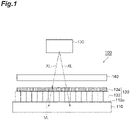
- FIG. 1 is a cross-sectional view schematically illustrating an example (X-ray detector) of a radiation detector.
- a radiation detector 100 illustrated in FIG. 1 includes a solid-state imaging device 110 and a scintillator panel 120.
- an X-ray irradiator (radiation irradiator) 130 for irradiating X-ray XL, an object (subject, imaging target, inspection target, or the like) 140, the scintillator panel 120, and the solid-state imaging device 110 are disposed in this order.
- the scintillator panel 120 is disposed on a light receiving surface 110a side of the solid-state imaging device 110.
- the scintillator panel 120 includes a fiber optic plate 122 and a scintillator 124 disposed on the fiber optic plate 122.
- the scintillator 124 is disposed on the light receiving surface side of the scintillator panel 120 and converts the radiation (for example, X-ray) incident on the scintillator 124 into visible light or the like.
- the object 140 is irradiated with the X-ray XL from the X-ray irradiator 130, and thus, absorption, scattering, diffraction, and the like occur in the object 140. Thereafter, the light traveling from the object 140 toward the scintillator 124 of the scintillator panel 120 is incident on the scintillator 124. Most of the incident light with respect to the scintillator 124 is converted into visible light VL or the like, but a portion of the incident light penetrates the scintillator 124 without being converted and travels toward the fiber optic plate 122 side.
- the fiber optic plate 122 to absorb the light penetrating the scintillator 124 without being converted by the scintillator 124 in this manner, the irradiation of the solid-state imaging device 110 with the X-ray XL can be suppressed. Accordingly, digital imaging can be performed while suppressing the occurrence of problems (increase in dark current, noise, or the like, occurrence of white spots in the output image, and the like) caused by the solid-state imaging device 110 being exposed to radiation.
- the X-ray irradiator 130 is not particularly limited as long as the X-ray irradiator 130 can irradiate X-rays.
- the tube voltage of the X-ray irradiator may be 25 KVp or more, 30 KVp or more, 35 KVp or more, 40 KVp or more, 45 KVp or more, 50 KVp or more, 55 KVp or more, 60 KVp or more, 65 KVp or more, 70 KVp or more, 75 KVp or more, or 80 KVp or more.
- the tube voltage of the X-ray irradiator may be 130 KVp or less, 120 KVp or less, 110 KVp or less, 100 KVp or less, 90 KVp or less, 85 KVp or less, 80 KVp or less, 75 KVp or less, 70 KVp or less, 65 KVp or less, 60 KVp or less, 50 KVp or less, 45 KVp or less, 40 KVp or less, or 35 KVp or less. From these viewpoints, the tube voltage of the X-ray irradiator may be 25 to 130 KVp.
- the solid-state imaging device 110 a CCD image sensor, a CMOS image sensor, and the like are exemplified.
- the scintillator 124 of the scintillator panel 120 contains, for example, cesium iodide as a main component and has a columnar crystal structure having a root on the side of the fiber optic plate.
- FIG. 2 is an enlarged perspective view illustrating an internal structure of the fiber optic plate.
- the fiber optic plate 122 includes a plurality of core glasses 122a, a clad glass 122b covering each of the core glasses 122a, and a light-absorbing glass 122c disposed between the plurality of core glasses 122a.
- the clad glass 122b may be separate from the core glass 122a and may be integrated with the core glass 122a.
- the core glass 122a is a fibrous member (long member) and is aligned and juxtaposed in a direction intersecting the axial direction.
- the core glass 122a penetrates from one surface to the other surface of the fiber optic plate 122.
- the core glass 122a can propagate light such as visible light incident from one end (end on the side of one surface of the fiber optic plate 122) to the other end (end on the side of the other surface of the fiber optic plate 122) while blocking X-rays.
- the length of the core glass 122a (length in the axial direction, the thickness of the fiber optic plate 122) is, for example, 0.1 to 250.
- the diameter of the core glass 122a is, for example, 0.001 to 0.05 mm.
- the cross section of the core glass 122a in the direction intersecting the axial direction has, for example, a circular shape.
- the clad glass 122b covers each outer peripheral portion of the core glass 122a.
- the length of the core glass 122a is equivalent to the length of the clad glass 122b.
- the cross section of the clad glass 122b in the direction intersecting the axial direction has, for example, an annular shape.
- the clad glass 122b can contain a network-forming oxide, a network-modified oxide, an intermediate oxide, or the like.
- the clad glass 122b may have a lower refractive index than the core glass 122a.
- the light-absorbing glass 122c is disposed between the plurality of core glasses 122a.
- the light-absorbing glass 122c is a long member.
- the light-absorbing glass 122c may have an absorbent property of absorbing light (stray light) leaking from the core glass 122a and the clad glass 122b.
- the light-absorbing glass 122c may be formed of a glass composition.
- the glass composition of the light-absorbing glass 122c may contain SiO 2 as a main component and may contain Fe 2 O 3 or the like.
- the diameter of the light-absorbing glass is not particularly limited, and as illustrated in FIG. 2 , the diameter of the light-absorbing glass may be smaller than the diameter of the core glass 122a and may be equivalent to the diameter of the core glass 122a.
- the light-absorbing glass may be disposed between the plurality of core glasses and may be disposed at the position of a portion of the core glass among the core glasses 122a in FIG. 2 . In this case, the light-absorbing glass 122c illustrated in FIG. 2 may not be disposed.
- the electron microscope (transmission electron microscope) of the present embodiment includes an electron beam source, an electron optical system, a sample mounting part, a scintillator panel of the present embodiment, and an imaging device.
- the electron beam source emits an electron beam.
- the electron optical system irradiates a sample with electron beams emitted from the electron beam source.
- the sample mounting part holds the sample.
- the sample mounting part is disposed between the electron beam source and the scintillator panel.
- the scintillator panel is disposed between the electron beam source and the imaging device. In the scintillator panel, the scintillator is disposed on the side of the electron beam source.
- the electron beam penetrating through or being scattered in the sample among the electron beams emitted from the electron beam source is converted into an optical image by the scintillator of the scintillator panel, and the optical image is captured by the imaging device.
- the imaging device a solid-state imaging device can be used.
- the optical image can be captured by the imaging device while suppressing problems caused by the electron beam penetrating the scintillator.
- FIG. 3 is a view schematically illustrating an example of an electron microscope (transmission electron microscope).
- An electron microscope 200 illustrated in FIG. 3 includes an electron gun (electron beam source) 210, an electron optical system 220, a sample mounting part 230, an electron optical system 240, a scintillator panel 250, and a solid-state imaging device 260 in this order.
- the scintillator panel 250 includes a fiber optic plate 252 and a scintillator 254 disposed on the fiber optic plate 252.
- the scintillator panel 250 is disposed on the light receiving surface side of the solid-state imaging device 260.
- the scintillator 254 is disposed on the light receiving surface side of the scintillator panel 250.
- the electron gun 210 emits an electron beam EB1.
- the electron optical system 220 irradiates a sample 230a of the sample mounting part 230 with the electron beams EB1 emitted from the electron gun 210.
- an electron beam EB2 penetrating through or being scattered in the sample 230a is focus-adjusted by the electron optical system 240 to be incident on the scintillator 254 and is converted into an optical image by the scintillator 254.
- the optical image including the information of the sample 230a can be captured by the solid-state imaging device 260.
- an object a subject, an imaging target, an inspection target, or the like
- a scintillator in the radiation detector of the present embodiment.
- the radiation blocking method of the present embodiment by using a fiber optic plate including a core glass having a small degree of coloration and an appropriate refractive index, it is possible to ensure excellent performance in an optical device while improving radiation blocking performance.
- the radiation directed to an imaging device may be blocked by the fiber optic plate.
- the radiation blocking method of the present embodiment may be an X-ray blocking method of blocking at least a portion (a portion or all) of X-rays directed to the imaging device by the fiber optic plate when an object is irradiated with the X-rays from the radiation irradiator in a state where the object is disposed between the radiation irradiator and the scintillator in the radiation detector of the present embodiment.
- the radiation blocking method of the present embodiment may be an electron beam blocking method of blocking at least a portion (a portion or all) of electron beams directed to the imaging device by the fiber optic plate when an object is irradiated with the electron beams from the radiation irradiator in a state where the object is disposed between the radiation irradiator and the scintillator in the radiation detector of the present embodiment.
- the present embodiment can be used, for example, for various sensors such as an image sensor, various cameras, electron microscopes, and the like.
- the present embodiment can be used for an area sensor or a line sensor.
- the present embodiment can be used in the medical and dental imaging fields, battery inspection (finished product inspection, in-process inspection, material inspection, or the like), electronic board inspection, insulating material inspection, electronic component and electronic device inspections, resin inspection, food inspection, and the like.
- the transition point (Tg), yield point (At), and linear thermal expansion coefficient ( ⁇ ) of the glass composition are measured using a thermal expansion meter (TD: Thermo Dilatometer, manufactured by Mac Science Co., Ltd., trade name: TD5000S).
- the density was measured using "ED-120T” manufactured by Mirage Trading Co., Ltd. in accordance with "JIS Z 8807:2012 Methods of measuring density and specific gravity of solid".
- the refractive index (d line) was measured in accordance with "JIS B 7071-2:2018 Measuring method for refractive index of optical glass - Part 2: Vee block refractometers method" using "KPR-2000" manufactured by Carnew Optical Industry Co., Ltd. Physical properties other than the refractive index (d line) were measured only for Examples.
- the refractive index (d line) was measured only for Examples and Comparative Examples 1 and 2. The measurement results are listed in Tables 1 to 4.
- the glass composition of Example was melted in an electric furnace for one hour, and after that, the melt was taken out from the electric furnace.
- the stirring of the melt was started and the stirring was performed until the melt was solidified, the state of the glass compositions was visually observed, and the devitrification resistance was evaluated based on the following criteria.
- the results are listed in Tables 1 to 3.
- a core glass was manufactured using the glass compositions of Example 17 and Comparative Example 1. After coating the core glass with clad glass, a single fiber was manufactured by performing heating to 810°C and performing drawing. After manufacturing a single fiber bundle by combining 61 single fibers, a multi-fiber base material was manufactured by inserting a light-absorbing glass into a gap of the single fiber bundle. Next, the multi-fiber base material was heated to 825°C to manufacture a multi-fiber. A multi multi-fiber base material was manufactured by combining 397 multi-fibers. Next, the multi multi-fiber base material was heated to 780°C to manufacture a multi multi-fiber. Next, an ingot was manufactured by combining tens of thousands of multi multi-fibers and then heating and fusing at 700°C. By polishing the ingot, a 30 mm ⁇ 20 mm fiber optic plate for an X-ray image sensor and a 250 mm ⁇ 7 mm fiber optic plate for an X-ray TDI camera were obtained.
- a scintillator panel including a scintillator having a thickness of 120 ⁇ m was manufactured by depositing a composition containing cesium iodide as a main component on one surface of the above-described fiber optic plate.
- CMOS manufactured by HAMAMATSU PHOTONICS K.K., trade name: S11680-71
- S11680-71 CMOS/fiber optic plate/scintillator
- the number of white spots in the output image was evaluated by 220 ⁇ Gy irradiation at an X-ray tube voltage of 70 kVp, the number of white spots was 434 in Comparative Example 1 and 271 in Example 17, and thus, it was confirmed that the radiation exposure of CMOS caused by X-rays was suppressed. Even when X-ray image sensors are manufactured in the same manner as in Example 17 using the glass compositions of Examples other than Example 17, the radiation exposure of CMOS can be suppressed as compared with Comparative Example 1.
- 100 radiation detector, 110, 260: solid-state imaging device, 110a: light receiving surface, 120, 250: scintillator panel, 122, 252: fiber optic plate, 122a: core glass, 122b: clad glass, 122c: light-absorbing glass, 124, 254: scintillator, 130: X-ray irradiator (radiation irradiator), 140: object, 200: electron microscope, 210: electron gun (electron beam source), 220: electron optical system, 230: sample mounting part, 230a: sample, EB1, EB2: electron beam, VL: visible light, XL: X-ray.
Landscapes
- Chemical & Material Sciences (AREA)
- Life Sciences & Earth Sciences (AREA)
- Physics & Mathematics (AREA)
- Engineering & Computer Science (AREA)
- Materials Engineering (AREA)
- Organic Chemistry (AREA)
- Chemical Kinetics & Catalysis (AREA)
- General Chemical & Material Sciences (AREA)
- Geochemistry & Mineralogy (AREA)
- Optics & Photonics (AREA)
- General Physics & Mathematics (AREA)
- Health & Medical Sciences (AREA)
- High Energy & Nuclear Physics (AREA)
- Molecular Biology (AREA)
- Spectroscopy & Molecular Physics (AREA)
- Analytical Chemistry (AREA)
- Biochemistry (AREA)
- General Health & Medical Sciences (AREA)
- Immunology (AREA)
- Pathology (AREA)
- Inorganic Chemistry (AREA)
- Glass Compositions (AREA)
- Measurement Of Radiation (AREA)
- Optical Fibers, Optical Fiber Cores, And Optical Fiber Bundles (AREA)
Abstract
Description
- The present invention relates to a fiber optic plate, a scintillator panel, a radiation detector, an electron microscope, an X-ray blocking method, and an electron beam blocking method.
- A fiber optic plate (also known as a fiber face plate aggregate or a fiber bundle plate aggregate; for example, trade name J11057 manufactured by HAMAMATSU PHOTONICS K.K.) is an optical device configured by bundling a plurality of optical fibers together, and the fiber optic plate can be used in various optical devices. The fiber optic plate includes, for example, a plurality of core glasses, a clad glass covering the core glass, and a light-absorbing glass disposed between the plurality of core glasses, and various compositions of a glass composition used for the core glass are considered (for example, refer to
Patent Literature 1 below). - Patent Literature 1:
Japanese Unexamined Patent Publication No. H9-71436 - With respect to the glass composition used for the core glass of the fiber optic plate, from the viewpoint of ensuring excellent performance in an optical device, an appropriate refractive index is required while suppressing coloration.
- One aspect of the present invention is to provide a fiber optic plate including a core glass having a low degree of coloration and an appropriate refractive index. Another aspect of the invention is to provide a scintillator panel including the above-described fiber optic plate. Another aspect of the present invention is to provide a radiation detector and an electron microscope including the above-described scintillator panel. Another aspect of the present invention is to provide an X-ray blocking method and an electron beam blocking method using the above-described fiber optic plate.
- In recent years, digital imaging is performed by irradiation with radiation from the side of an object (subject, imaging object, inspection object, or the like) toward an imaging device in a state where a scintillator panel including a fiber optic plate and a scintillator is interposed between the object and the imaging device. In this case, when the imaging device is exposed to the radiation, there may be a problem that dark current, noise, or the like increase, a problem that white spots occur in an output image, and the like. For this reason, it is required to improve radiation blocking performance of blocking the radiation while transmitting visible light or the like in the fiber optic plate. On the other hand, the present inventor has studied composition of a glass composition used for a core glass and found a problem that it is not easy to obtain a small degree of coloration and an appropriate refractive index in the core glass while improving radiation blocking performance. Then, the present inventor has found that the problem can be solved when the core glass contains specific components.
- One aspect of the present invention is to provide a fiber optic plate including a plurality of core glasses, a clad glass covering the core glass, and a light-absorbing glass disposed between the plurality of core glasses, wherein a content of TiO2 in the core glasses is 7% by mass or less, a content of B2O3 in the core glass is 15% by mass or more, and a content of WO3 in the core glass is more than 0% by mass.
- According to the fiber optic plate of one aspect of the present invention, it is possible to obtain a small degree of coloration and an appropriate refractive index in the core glass. According to such a fiber optic plate, it is possible to ensure excellent performance in an optical device. According to the fiber optic plate of one aspect of the present invention, it is possible to obtain a small degree of coloration and an appropriate refractive index in the core glass while improving radiation blocking performance.
- Incidentally, in some cases, in the fiber optic plate used in the field of imaging, lead glass may be used as a glass composition of the core glass. However, since lead is subject to hazardous substance regulations such as RoHS regulation and has a large environmental load, it is required not to use lead glass. In contrast, according to the fiber optic plate of one aspect of the present invention, even when the core glass does not contain lead, it is possible to obtain a small degree of coloration and an appropriate refractive index of the core glass while improving radiation blocking performance.
- Another aspect of the present invention provides a scintillator panel including the above-described fiber optic plate and a scintillator disposed on the fiber optic plate.
- Another aspect of the present invention provides a radiation detector including: a radiation irradiator; an imaging device; and the above-described scintillator panel, wherein the scintillator panel is disposed between the radiation irradiator and the imaging device, and the scintillator is disposed on the side of the radiation irradiator in the scintillator panel.
- Another aspect of the present invention provides an electron microscope including: an electron beam source; an electron optical system irradiating a sample with electron beams emitted from the electron beam source; a sample mounting part holding the sample; the above-described scintillator panel; and an imaging device, wherein the scintillator panel is disposed between the electron beam source and the imaging device, the scintillator is disposed on the side of the electron beam source in the scintillator panel, an electron beam penetrating through or being scattered in the sample among the electron beams is converted into an optical image by the scintillator of the scintillator panel, and the optical image is captured by the imaging device.
- Another aspect of the present invention is to provide an X-ray blocking method of blocking at least a portion of X-rays directed to the imaging device by the fiber optic plate, when an object is irradiated with the X-rays from a radiation irradiator in a state where the object is disposed between the radiation irradiator and the scintillator in the above-described radiation detector.
- Another aspect of the present invention is to provide an electron beam blocking method of blocking at least a portion of electron beams directed to the imaging device by the fiber optic plate, when an object is irradiated with the electron beams from a radiation irradiator in a state where the object is disposed between the radiation irradiator and the scintillator in the above-described radiation detector.
- According to one aspect of the present invention, it is possible to provide a fiber optic plate including a core glass having a low degree of coloration and an appropriate refractive index. According to another aspect of the present invention, it is possible to provide a scintillator panel including the fiber optic plate. According to another aspect of the present invention, it is possible to provide a radiation detector and an electron microscope including the scintillator panel. According to another aspect of the present invention, it is possible to provide a radiation blocking method using the fiber optic plate, and it is possible to provide an X-ray blocking method and an electron beam blocking method using the fiber optic plate.
-
-
FIG. 1 is a cross-sectional view schematically illustrating a radiation detector of an embodiment of the present invention. -
FIG. 2 is an enlarged perspective view illustrating an internal structure of a fiber optic plate of an embodiment of the present invention. -
FIG. 3 is a view schematically illustrating an electron microscope of an embodiment of the present invention. -
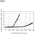
FIG. 4 is a view illustrating an evaluation result of life performance in Example. - Hereinafter, embodiments for carrying out the present invention will be described in detail with reference to the drawings. It is noted that, in each drawing, the same or corresponding components are denoted by the same reference numerals, and duplicate description will be omitted. The present invention is not limited to the following embodiments.
- In the present specification, a numerical range indicated using "to" indicates a range including the numerical values before and after "to" as the minimum value and the maximum value, respectively. In the numerical range described stepwise in the present specification, upper limit values or lower limit values of the numerical range of one step can be arbitrarily combined with upper limit values or lower limit values of the numerical range of another step. In the numerical range described in the present specification, upper limit values or lower limit values of the numerical range may be replaced with the values illustrated in Examples.
- A fiber optic plate (FOP) of the present embodiment includes a plurality of core glasses, a clad glass covering the core glass, and a light-absorbing glass disposed between the plurality of core glasses. In the fiber optic plate (glass composition constituting the fiber optic plate) of the present embodiment, a content of TiO2 in the core glass is 7% by mass or less, a content of B2O3 in the core glass is 15% by mass or more, and a content of WO3 in the core glass is more than 0% by mass.
- According to the fiber optic plate of the present embodiment, it is possible to obtain a small degree of coloration and an appropriate refractive index (for example, a d-line refractive index nd of 1.88 or less) in the core glass. According to such a fiber optic plate, it is possible to ensure excellent performance in an optical device. For example, when the core glass of the fiber optic plate has an appropriate refractive index, the refractive index of the fiber optic plate and the refractive index of the scintillator is likely to be the same, and thus, it is possible to suppress surface reflection at the boundary of the fiber optic plate and the scintillator in the scintillator panel including the fiber optic plate and the scintillator.
- According to the fiber optic plate of the present embodiment, it is possible to obtain a small degree of coloration and an appropriate refractive index in the core glass while improving radiation blocking performance (for example, X-ray blocking performance or electron beam blocking performance), and it is possible to selectively block radiations (for example, X-rays or electron beams) while transmitting visible light. According to the fiber optic plate of the present embodiment, since excellent radiation blocking performance can be obtained, when an imaging device is used, it is possible to suppress the occurrence of problems (the increase in dark current, noise, or the like, occurrence of the white spots in the output image, or the like) due to exposure of the imaging device to radiation. According to the fiber optic plate of the present embodiment, even when the core glass does not contain lead, it is possible to obtain a small degree of coloration and an appropriate refractive index of the core glass while improving the radiation blocking performance (for example, X-ray blocking performance or electron beam blocking performance). According to the fiber optic plate of the present embodiment, it is possible to block at least a portion of the radiations, and it is also possible to block all of the radiations.
- Incidentally, in order to improve the resolution and the like, it is effective to thin the scintillator of the optical device, however, in some cases, as the thinning is performed, the radiation is likely to penetrate the scintillator and the imaging device is likely to be exposed to radiation. On the other hand, according to the present embodiment, even when the thinning is performed in order to improve the resolution and the like, the radiations (for example, X-rays or electron beams) can be blocked by the fiber optic plate, and thus, it is possible to obtain excellent resolution while suppressing the occurrence of problems caused by exposure of the imaging device to the radiations.
- The fiber optic plate of the present embodiment can be used for various optical devices including the fiber optic plate. The fiber optic plate of the present embodiment can have a function of transmitting light or the like incident from an incident surface to an emitting surface and can be used as an optical waveguide for optical devices such as a radiation detector, an electron microscope, an image intensifier, a CCD coupling, and a fingerprint detection device. The radiation detector includes, for example, a radiation imager (X-ray image sensor, X-ray TDI camera, or the like). The radiation detector may be used to detect the radiation in addition to acquiring an image with a radiation imager. According to the present embodiment, it is possible to provide an application of the fiber optic plate for radiation blocking. According to the present embodiment, it is possible to provide a glass composition for radiation blocking. As radiation, electromagnetic radiation such as X-rays and γ-rays; and particle radiation such as electron beams are exemplified.
- Hereinafter, the constituent components of the core glass and the like will be described. The content of the constituent components of the core glass can be measured, for example, by fluorescent X-ray analysis or ICP emission spectroscopic analysis. As the content of each oxide in the core glass, the content of the oxide as a raw material for compounding can also be used.
- From the viewpoint of obtaining a small degree of coloration and an appropriate refractive index while improving radiation blocking performance, the content of TiO2 in the core glass is 7% by mass or less based on the entire core glasses. The core glass may contain TiO2 (the content may be more than 0% by mass) and may not contain TiO2 (the content may be 0% by mass). The content of TiO2 may be 0 to 7% by mass.
- The content of TiO2 may be in the following range based on the entire core glasses. From the viewpoint of easily obtaining a small degree of coloration and an appropriate refractive index while improving radiation blocking performance, the content of TiO2 may be 6% by mass or less, 5% by mass or less, 4.5% by mass or less, 4% by mass or less, 3% by mass or less, 2% by mass or less, 1% by mass or less, less than 1% by mass, 0.5% by mass or less, 0.3% by mass or less, 0.1% by mass or less, 0.05% by mass or less, or 0.01% by mass or less. From the viewpoint of easily increasing the refractive index and the viewpoint of easily obtaining excellent devitrification resistance, the content of TiO2 may be 0.00001% by mass or more, 0.0001% by mass or more, or 0.001% by mass or more.
- From the viewpoint of obtaining an appropriate refractive index, the viewpoint of easily reducing the linear thermal expansion coefficient, and the viewpoint of easily obtaining excellent devitrification resistance, the content of B2O3 in the core glass is 15% by mass or more based on the entire core glasses. The content of B2O3 may be in the following range based on the entire core glasses. From the viewpoint of easily obtaining an appropriate refractive coefficient, the viewpoint of easily further reducing the linear thermal expansion coefficient, the viewpoint of easily reducing a transition point and a yield point, and the viewpoint of easily further obtaining excellent devitrification resistance, the content of B2O3 may be more than 15% by mass, 15.5% by mass or more, more than 15.5% by mass, 16% by mass or more, 17% by mass or more, 18% by mass or more, more than 18% by mass, or 18.5% by mass or more. From the viewpoint of easily maintaining a high content of other components that contribute to the improvement of radiation blocking performance, the content of B2O3 may be 33% by mass or less, 31% by mass or less, 30% by mass or less, 28% by mass or less, 25% by mass or less, less than 25% by mass, 23% by mass or less, 22% by mass or less, less than 22% by mass, 21% by mass or less, less than 21% by mass, 20.5% by mass or less, 20% by mass or less, less than 20% by mass, 19.5% by mass or less, 19% by mass or less, less than 19% by mass, or 18.5% by mass or less. From these viewpoints, the content of B2O3 may be 15 to 33% by mass, 18.5 to 33% by mass, or the like.
- From the viewpoint of reducing the degree of coloration while improving radiation blocking performance and the viewpoint of easily increasing the refractive index, the content of WO3 in the core glass is more than 0% by mass based on the entire core glasses. The content of WO3 may be in the following range based on the entire core glasses. From the viewpoint of easily improving the radiation blocking performance and the viewpoint of easily further increasing the refractive index, the content of WO3 may be 1% by mass or more, 2% by mass or more, 3% by mass or more, 5% by mass or more, 7% by mass or more, 9% by mass or more, 10% by mass or more, more than 10% by mass, 11% by mass or more, 12% by mass or more, 12.5% by mass or more, more than 12.5% by mass, 13% by mass or more, 13.5% by mass or more, 14% by mass or more, 14.5% by mass or more, or 15% by mass or more. From the viewpoint of easily reducing the degree of coloration and the viewpoint of easily obtaining excellent devitrification resistance, the content of WO3 may be 25% by mass or less, 22.5% by mass or less, 20% by mass or less, 19% by mass or less 18.5% by mass or less, 18% by mass or less, 17.5% by mass or less, 17% by mass or less, 16.5% by mass or less, 16% by mass or less, 15.5% by mass or less, or 15% by mass or less. From these viewpoints, the content of WO3 may be more than 0% by mass and 25% by mass or less, 10 to 15% by mass, or the like.
- The core glass may contain SiO2 (the content may be more than 0% by mass) and may not contain SiO2 (the content may be 0% by mass). The content of SiO2 may be in the following range based on the entire core glasses. From the viewpoint of easily increasing the transition point and the yield point, the content of SiO2 may be 10% by mass or less, less than 10% by mass, 8% by mass or less, 7% by mass or less, 6% by mass or less, less than 6% by mass, 5.5% by mass or less, 5% by mass or less, less than 5% by mass, 4.5% by mass or less, 4% by mass or less, less than 4% by mass, or 3.5% by mass or less. From the viewpoint of easily obtaining excellent devitrification resistance and the viewpoint of easily reducing the linear thermal expansion coefficient, the content of SiO2 may be 0.1% by mass or more, 0.5% by mass or more, 1% by mass or more, more than 1% by mass, 1.5% by mass or more, 2% by mass or more, 2.5% by mass or more, 3% by mass or more, more than 3% by mass, or 3.5% by mass or more. From these viewpoints, the content of SiO2 may be 0 to 10% by mass or the like.
- The core glass may contain Gd2O3 (the content may be more than 0% by mass) and may not contain Gd2O3 (the content may be 0% by mass). The content of Gd2O3 may be in the following range based on the entire core glasses. From the viewpoint of easily obtaining excellent devitrification resistance, the content of Gd2O3 may be 40% by mass or less, 37.5% by mass or less, 35% by mass or less, 33% by mass or less, 30% by mass or less, 28% by mass or less 27.5% by mass or less, 27% by mass or less, 26.5% by mass or less, 26% by mass or less, 25.5% by mass or less, or 25% by mass or less. From the viewpoint of easily improving the radiation blocking performance, the viewpoint of easily increasing the refractive index, and the viewpoint of easily obtaining excellent devitrification resistance, the content of Gd2O3 may be 0.1% by mass or more, 0.5% by mass or more, 1% by mass or more, 5% by mass or more, 10% by mass or more, 15% by mass or more, 20% by mass or more, 22.5% by mass or more, or 25% by mass or more. From these viewpoints, the content of Gd2O3 may be 0 to 40% by mass, 0 to 25% by mass, or the like.
- The core glass may contain ZrO2 (the content may be more than 0% by mass) and may not contain ZrO2 (the content may be 0% by mass). The content of ZrO2 may be in the following range based on the entire core glasses. From the viewpoint of easily obtaining excellent devitrification resistance, the content of ZrO2 may be 10% by mass or less, 9% by mass or less, 8% by mass or less, 7.5% by mass or less, less than 7.5% by mass, 7% by mass or less, 6% by mass or less, 5.5% by mass or less, 5% by mass or less, 4.5% by mass or less, 4% by mass or less, 3.5% by mass or less, 3% by mass or less, or 2.5% by mass or less. From the viewpoint of easily increasing the refractive index and easily obtaining excellent devitrification resistance, the content of ZrO2 may be 0.1% by mass or more, 0.5% by mass or more, 1% by mass or more, 1.5% by mass or more, 2% by mass or more, more than 2% by mass, 2.2% by mass or more, 2.3% by mass or more, 2.4% by mass or more, or 2.5% by mass or more. From these viewpoints, the content of ZrO2 may be 0 to 10% by mass, 0 to 2.5% by mass, or the like.
- The core glass may contain La2O3 (the content may be more than 0% by mass) and may not contain La2O3 (the content may be 0% by mass). The content of La2O3 may be in the following range based on the entire core glasses. From the viewpoint of easily obtaining excellent devitrification resistance, the content of La2O3 may be 40% by mass or less, less than 40% by mass, 37.5% by mass or less, 35% by mass or less, less than 35% by mass, 33% by mass or less, 32.5% by mass or less, or 32% by mass or less. From the viewpoint of easily improving the radiation blocking performance and the viewpoint of increasing the refractive index, the content of La2O3 may be 0.1% by mass or more, 0.5% by mass or more, 1% by mass or more, 5% by mass or more, 10% by mass or more, 15% by mass or more, 20% by mass or more, 22.5% by mass or more, 25% by mass or more, 27% by mass or more, 27.5% by mass or more, 28% by mass or more, 29% by mass or more, 30% by mass or more, more than 30% by mass, 30.5% by mass or more, 31% by mass or more, 31.5% by mass or more, or 32% by mass or more. From these viewpoints, the content of La2O3 may be 0 to 40% by mass or the like.
- From the viewpoint of easily obtaining excellent devitrification resistance and the like, the core glass may contain ZnO (the content may be more than 0% by mass). ZnO may not be contained (the content may be 0% by mass), and the content of ZnO may be in the following range based on the entire core glasses. From the viewpoint of easily maintaining a high content of other components that contribute to the improvement of radiation blocking performance, the content of ZnO may be 10% by mass or less, 8% by mass or less, 7% by mass or less, 6% by mass or less, 5% by mass or less, less than 5% by mass, 4% by mass or less, 3.5% by mass or less, 3.3% by mass or less, 3.2% by mass or less, 3% by mass or less, 2% by mass or less, 1% by mass or less, or less than 1% by mass. From these viewpoints, the content of ZnO may be 0 to 10% by mass or the like.
- The core glass may contain Nb2O5 (the content may be more than 0% by mass) and may not contain Nb2O5 (the content may be 0% by mass). The content of Nb2O5 may be in the following range based on the entire core glasses. From the viewpoint of easily obtaining excellent devitrification resistance, the content of Nb2O5 may be 16% by mass or less, 15% by mass or less, 12% by mass or less, 10% by mass or less, 8% by mass or less, 7% by mass or less, 6% by mass or less, 5% by mass or less, less than 5% by mass, 4% by mass or less, or 3.5% by mass or less. From the viewpoint of easily increasing the refractive index, the content of Nb2O5 may be 0.1% by mass or more, 0.5% by mass or more, 1% by mass or more, more than 1% by mass, 1.5% by mass or more, 2% by mass or more, more than 2% by mass, 2.5% by mass or more, 3% by mass or more, more than 3% by mass, 3.25% by mass or more, or 3.5% by mass or more. From these viewpoints, the content of Nb2O5 may be 0 to 10% by mass or the like.
- The core glass may contain a network former (NWF) oxide that forms a network of glass, a network modifier (NWM) oxide that imparts appropriate properties to glass by melting with the NWF oxide, an intermediate oxide having intermediate properties of the NWF oxide and the NWM oxide, or the like. As the NWF oxide, B2O3, SiO2, ZrO2, and the like are exemplified. As the NWM oxide, WO3, Gd2O3, La2O3, Nb2O5, and the like are exemplified. As the intermediate oxide, TiO2, ZrO2, ZnO, and the like are exemplified.
- The content of NWF oxide in the core glass (total amount of NWF oxide) may be in the following range based on the entire core glasses. From the viewpoint of easily improving the radiation blocking performance, the content of NWF oxide may be 40% by mass or less, less than 40% by mass, 35% by mass or less, 30% by mass or less, less than 30% by mass, 29% by mass or less, 28% by mass or less, 27% by mass or less, 26% by mass or less, 25% by mass or less, or 24.5% by mass or less. From the viewpoint of easily obtaining excellent devitrification resistance and the viewpoint of easily reducing the degree of coloration, the content of NWF oxide may be 10% by mass or more, 15% by mass or more, 20% by mass or more, 21% by mass or more, 22% by mass or more, 23% by mass or more, 24% by mass or more, or 24.5% by mass or more. From these viewpoints, the content of NWF oxide may be 10 to 40% by mass or the like.
- The content of NWM oxide in the core glass (total amount of NWM oxide) may be in the following range based on the entire core glasses. From the viewpoint of easily maintaining excellent devitrification resistance, the content of NWM oxide may be 80% by mass or less, 79% by mass or less, 78% by mass or less, 77.5% by mass or less, 77% by mass or less, 76.5% by mass or less, 76% by mass or less, or 75.5% by mass or less. From the viewpoint of easily improving the radiation blocking performance, the content of NWM oxide may be 60% by mass or more, 62.5% by mass or more, 65% by mass or more, 66% by mass or more, 67% by mass or more, 68% by mass or more, 69% by mass or more, 70% by mass or more, 70.5% by mass or more, 71% by mass or more, 71.5% by mass or more, 72% by mass or more, 72.5% by mass or more, 73% by mass or more, 73.5% by mass or more, 74% by mass or more, 74.5% by mass or more, 75% by mass or more, or 75.5% by mass or more. From these viewpoints, the content of NWM oxide may be 60 to 80% by mass or the like.
- The content of intermediate oxides (total amount of intermediate oxides) in the core glass may be in the following range based on the entire core glasses. From the viewpoint of easily increasing the content of NWM oxide and the viewpoint of easily adjusting the refractive index (for example, easily suppressing an excessive increase in refractive index), the content of the intermediate oxide may be 20% by mass or less, 17.5% by mass or less, 15% by mass or less, 13% by mass or less, 12.5% by mass or less, 12% by mass or less, 11% by mass or less, 10% by mass or less, 9% by mass or less, 8.5% by mass or less, 8% by mass or less, 7% by mass or less, 6% by mass or less, 5% by mass or less, 4% by mass or less, 3% by mass or less, or 2.5% by mass or less. From the viewpoint of easily obtaining excellent devitrification resistance and the viewpoint of easily obtaining excellent chemical durability, the content of the intermediate oxide may be 0% by mass or more, more than 0% by mass, 0.5% by mass or more, 1% by mass or more, more than 1% by mass, 1.5% by mass or more, 2% by mass or more, more than 2% by mass, 2.25% by mass or more, or 2.5% by mass or more. From these viewpoints, the content of the intermediate oxide may be 0 to 20% by mass or the like.
- The core glass may contain CeO2 and may not contain CeO2. The content of CeO2 in the core glass may be 0 to 3% by mass, and may be more than 0% by mass and 3% by mass or less based on the entire core glasses. When the core glass contains CeO2, it is easy to obtain the effect of reducing the coloration of the glass due to X-ray exposure. When the content of CeO2 in the core glass is 3% by mass or less, the shift of the absorption edge in the ultraviolet region to the visible region of the glass to the long wavelength side can be easily suppressed, and the decrease in visible light transmission can be easily suppressed.
- The core glass may contain constituent components other than the above-described oxides. As such other constituent components, Bi2O3, Ta2O5, BaO, FeO, CO2O3, and the like are exemplified. The core glass may contain at least one of these other constituent components (the content may be more than 0% by mass) and may not contain at least one of these other constituent components (the content may be 0% by mass). The content of at least one of these other constituent components may be 0.1% by mass or less based on the entire core glass.
- The refractive index nd of the d-line in the core glass is 1.88 or less and may be in the following range. The nd of the core glass may be 1.87 or less, 1.865 or less, 1.86 or less, 1.855 or less, 1.85 or less, 1.849 or less, 1.848 or less, 1.847 or less, 1.846 or less, 1.845 or less, 1.844 or less, 1.8438 or less, 1.8436 or less, 1.8434 or less, or 1.8433 or less. The nd of the core glass may be 1.8 or more, 1.81 or more, 1.82 or more, 1.83 or more, 1.835 or more, or 1.84 or more. From these viewpoints, the nd of the core glass may be 1.8 to 1.88 or the like.
- The transition point of the core glass may be in the following range. The transition point may be 680°C or less, 679°C or less, 678°C or less, 675°C or less, 674°C or less, or 673°C or less. The transition point may be 560°C or more, 580°C or more, 600°C or more, 620°C or more, 630°C or more, 640°C or more, 645°C or more, 650°C or more, 655°C or more, 660°C or more, 665°C or more, 668°C or more, or 670°C or more. From these viewpoints, the transition point may be 560 to 680°C or the like.
- The yield point of the core glass may be in the following range. The yield point may be 720°C or less, 718°C or less, 716°C or less, 714°C or less, 712°C or less, 710°C or less, 709°C or less, or 708°C or less. The yield points may be 610°C or more, 620°C or more, 630°C or more, 640°C or more, 650°C or more, 660°C or more, 670°C or more, 680°C or more, 685°C or more, 688°C or more, 689°C or more, 690°C or more, 691°C or more, 693°C or more, 695 or more, 697°C or more, 699°C or more, 700°C or more, or 705°C or more. From these viewpoints, the yield point may be 610 to 720°C, 610 to 710°C, or the like.
- The linear thermal expansion coefficient of the core glass may be in the following range (unit: ×10-7/°C). The linear thermal expansion coefficient may be 95 or less, 92 or less, 90 or less, 87 or less, 85 or less, 84 or less, 83 or less, 82 or less, 81 or less, or 80 or less. The linear thermal expansion coefficient may be 70 or more, 72 or more, 74 or more, 75 or more, 76 or more, 77 or more, 78 or more, 79 or more, or 80 or more. From these viewpoints, the linear thermal expansion coefficient may be 70 to 95, 70 to 90, or the like. As the linear thermal expansion coefficient, for example, a linear thermal expansion coefficient in a temperature range of 100 to 300°C can be used.
- The density of the core glass may be in the following range (unit: g/cm3). Density may be 5.5 or less, 5.45 or less, 5.4 or less, 5.35 or less, 5.3 or less, 5.25 or less, 5.2 or less, 5.19 or less, or 5.18 or less. The density may be 5 or more, 5.05 or more, 5.1 or more, or 5.15 or more. From these viewpoints, the density may be 5 to 5.5 or the like.
- A scintillator panel of the present embodiment includes a fiber optic plate of the present embodiment and a scintillator disposed on the fiber optic plate. The fiber optic plate and the scintillator may be in contact with each other.
- The scintillator may contain cesium iodide and may contain the cesium iodide as a main component. Further, the scintillator may contain gadolinium oxysulfide and may contain the gadolinium oxysulfide as a main component. The scintillator may contain thallium, sodium, terbium, praseodymium or the like as an activator in addition to the cesium iodide or the gadolinium oxysulfide. The scintillator may include a columnar crystal (for example, a columnar crystal containing cesium iodide), and may have a structure in which a plurality of columnar crystals is disposed. The columnar crystal may have a root on the side of the fiber optic plate. The thickness of the scintillator is, for example, 50 to 1000 µm or 80 to 750 µm.
- The scintillator panel of the present embodiment may have a protective film covering at least a portion of the side (radiation incident side, for example, the surface of the scintillator on the radiation incident side) opposite to the fiber optic plate in the scintillator. Accordingly, deliquescence can be suppressed when the scintillator has a deliquescent property. The protective film can cover a portion or all of the side oppose to the fiber optic plate in the scintillator. As the constituent material of the protective film, an organic film made of polyparaxylylene or the like; an inorganic film made of a metal, an oxide thereof or the like; and a hybrid film of the above-described organic film and inorganic film, or the like is exemplified.
- The radiation detector of the present embodiment includes a radiation irradiator (for example, an X-ray irradiator or an electron beam irradiator), an imaging device, and a scintillator panel of the present embodiment. The scintillator panel is disposed between the radiation irradiator and the imaging device. In the scintillator panel, the scintillator is disposed on the side of the radiation irradiator (the light receiving surface side of the scintillator panel). The fiber optic plate of the scintillator panel and the imaging device may be in contact with each other. As the imaging device, a solid-state imaging device can be used.
-
FIG. 1 is a cross-sectional view schematically illustrating an example (X-ray detector) of a radiation detector. Aradiation detector 100 illustrated inFIG. 1 includes a solid-state imaging device 110 and ascintillator panel 120. In theradiation detector 100, an X-ray irradiator (radiation irradiator) 130 for irradiating X-ray XL, an object (subject, imaging target, inspection target, or the like) 140, thescintillator panel 120, and the solid-state imaging device 110 are disposed in this order. Thescintillator panel 120 is disposed on alight receiving surface 110a side of the solid-state imaging device 110. Thescintillator panel 120 includes afiber optic plate 122 and ascintillator 124 disposed on thefiber optic plate 122. Thescintillator 124 is disposed on the light receiving surface side of thescintillator panel 120 and converts the radiation (for example, X-ray) incident on thescintillator 124 into visible light or the like. - The
object 140 is irradiated with the X-ray XL from theX-ray irradiator 130, and thus, absorption, scattering, diffraction, and the like occur in theobject 140. Thereafter, the light traveling from theobject 140 toward thescintillator 124 of thescintillator panel 120 is incident on thescintillator 124. Most of the incident light with respect to thescintillator 124 is converted into visible light VL or the like, but a portion of the incident light penetrates thescintillator 124 without being converted and travels toward thefiber optic plate 122 side. In theradiation detector 100, by allowing thefiber optic plate 122 to absorb the light penetrating thescintillator 124 without being converted by thescintillator 124 in this manner, the irradiation of the solid-state imaging device 110 with the X-ray XL can be suppressed. Accordingly, digital imaging can be performed while suppressing the occurrence of problems (increase in dark current, noise, or the like, occurrence of white spots in the output image, and the like) caused by the solid-state imaging device 110 being exposed to radiation. - The
X-ray irradiator 130 is not particularly limited as long as theX-ray irradiator 130 can irradiate X-rays. The tube voltage of the X-ray irradiator may be 25 KVp or more, 30 KVp or more, 35 KVp or more, 40 KVp or more, 45 KVp or more, 50 KVp or more, 55 KVp or more, 60 KVp or more, 65 KVp or more, 70 KVp or more, 75 KVp or more, or 80 KVp or more. The tube voltage of the X-ray irradiator may be 130 KVp or less, 120 KVp or less, 110 KVp or less, 100 KVp or less, 90 KVp or less, 85 KVp or less, 80 KVp or less, 75 KVp or less, 70 KVp or less, 65 KVp or less, 60 KVp or less, 50 KVp or less, 45 KVp or less, 40 KVp or less, or 35 KVp or less. From these viewpoints, the tube voltage of the X-ray irradiator may be 25 to 130 KVp. As the solid-state imaging device 110, a CCD image sensor, a CMOS image sensor, and the like are exemplified. Thescintillator 124 of thescintillator panel 120 contains, for example, cesium iodide as a main component and has a columnar crystal structure having a root on the side of the fiber optic plate. -
FIG. 2 is an enlarged perspective view illustrating an internal structure of the fiber optic plate. Thefiber optic plate 122 includes a plurality ofcore glasses 122a, aclad glass 122b covering each of thecore glasses 122a, and a light-absorbingglass 122c disposed between the plurality ofcore glasses 122a. Theclad glass 122b may be separate from thecore glass 122a and may be integrated with thecore glass 122a. - The
core glass 122a is a fibrous member (long member) and is aligned and juxtaposed in a direction intersecting the axial direction. Thecore glass 122a penetrates from one surface to the other surface of thefiber optic plate 122. Thecore glass 122a can propagate light such as visible light incident from one end (end on the side of one surface of the fiber optic plate 122) to the other end (end on the side of the other surface of the fiber optic plate 122) while blocking X-rays. - The length of the
core glass 122a (length in the axial direction, the thickness of the fiber optic plate 122) is, for example, 0.1 to 250. The diameter of thecore glass 122a is, for example, 0.001 to 0.05 mm. The cross section of thecore glass 122a in the direction intersecting the axial direction has, for example, a circular shape. - The
clad glass 122b covers each outer peripheral portion of thecore glass 122a. The length of thecore glass 122a is equivalent to the length of the cladglass 122b. The cross section of the cladglass 122b in the direction intersecting the axial direction has, for example, an annular shape. Theclad glass 122b can contain a network-forming oxide, a network-modified oxide, an intermediate oxide, or the like. Theclad glass 122b may have a lower refractive index than thecore glass 122a. - The light-absorbing
glass 122c is disposed between the plurality ofcore glasses 122a. The light-absorbingglass 122c is a long member. The light-absorbingglass 122c may have an absorbent property of absorbing light (stray light) leaking from thecore glass 122a and theclad glass 122b. The light-absorbingglass 122c may be formed of a glass composition. The glass composition of the light-absorbingglass 122c may contain SiO2 as a main component and may contain Fe2O3 or the like. The diameter of the light-absorbing glass is not particularly limited, and as illustrated inFIG. 2 , the diameter of the light-absorbing glass may be smaller than the diameter of thecore glass 122a and may be equivalent to the diameter of thecore glass 122a. The light-absorbing glass may be disposed between the plurality of core glasses and may be disposed at the position of a portion of the core glass among thecore glasses 122a inFIG. 2 . In this case, the light-absorbingglass 122c illustrated inFIG. 2 may not be disposed. - The electron microscope (transmission electron microscope) of the present embodiment includes an electron beam source, an electron optical system, a sample mounting part, a scintillator panel of the present embodiment, and an imaging device. The electron beam source emits an electron beam. The electron optical system irradiates a sample with electron beams emitted from the electron beam source. The sample mounting part holds the sample. The sample mounting part is disposed between the electron beam source and the scintillator panel. The scintillator panel is disposed between the electron beam source and the imaging device. In the scintillator panel, the scintillator is disposed on the side of the electron beam source. In the electron microscope of the present embodiment, the electron beam penetrating through or being scattered in the sample among the electron beams emitted from the electron beam source is converted into an optical image by the scintillator of the scintillator panel, and the optical image is captured by the imaging device. As the imaging device, a solid-state imaging device can be used. In the electron microscope of the present embodiment, even when the electron beam penetrating through or being scattered in the sample penetrates the scintillator, by blocking the electron beam with the fiber optic plate, the optical image can be captured by the imaging device while suppressing problems caused by the electron beam penetrating the scintillator.
-
FIG. 3 is a view schematically illustrating an example of an electron microscope (transmission electron microscope). Anelectron microscope 200 illustrated inFIG. 3 includes an electron gun (electron beam source) 210, an electronoptical system 220, asample mounting part 230, an electronoptical system 240, ascintillator panel 250, and a solid-state imaging device 260 in this order. Thescintillator panel 250 includes afiber optic plate 252 and ascintillator 254 disposed on thefiber optic plate 252. Thescintillator panel 250 is disposed on the light receiving surface side of the solid-state imaging device 260. Thescintillator 254 is disposed on the light receiving surface side of thescintillator panel 250. - The
electron gun 210 emits an electron beam EB1. The electronoptical system 220 irradiates asample 230a of thesample mounting part 230 with the electron beams EB1 emitted from theelectron gun 210. Among the electron beams EB1, an electron beam EB2 penetrating through or being scattered in thesample 230a is focus-adjusted by the electronoptical system 240 to be incident on thescintillator 254 and is converted into an optical image by thescintillator 254. The optical image including the information of thesample 230a can be captured by the solid-state imaging device 260. In theelectron microscope 200, even when the electron beam EB2 penetrating through or being scattered in thesample 230a penetrates thescintillator 254, by blocking the electron beam EB2 with thefiber optic plate 252, it is possible to capture the optical image by the solid-state imaging device 260 while suppressing problems caused by the electron beam EB2 penetrating thescintillator 254. - According to the present embodiment, it is possible to provide a radiation blocking method of blocking at least a portion (a portion or all) of radiations directed to an imaging device by a fiber optic plate, when an object (a subject, an imaging target, an inspection target, or the like) is irradiated with the radiations from a radiation irradiator in a state where the object is disposed between the radiation irradiator and a scintillator in the radiation detector of the present embodiment. According to the radiation blocking method of the present embodiment, by using a fiber optic plate including a core glass having a small degree of coloration and an appropriate refractive index, it is possible to ensure excellent performance in an optical device while improving radiation blocking performance. In the radiation blocking method of the present embodiment, in the radiation measurement for detecting or imaging the radiation penetrating or being absorbed, scattered, or diffracted by the object, the radiation directed to an imaging device may be blocked by the fiber optic plate. The radiation blocking method of the present embodiment may be an X-ray blocking method of blocking at least a portion (a portion or all) of X-rays directed to the imaging device by the fiber optic plate when an object is irradiated with the X-rays from the radiation irradiator in a state where the object is disposed between the radiation irradiator and the scintillator in the radiation detector of the present embodiment. The radiation blocking method of the present embodiment may be an electron beam blocking method of blocking at least a portion (a portion or all) of electron beams directed to the imaging device by the fiber optic plate when an object is irradiated with the electron beams from the radiation irradiator in a state where the object is disposed between the radiation irradiator and the scintillator in the radiation detector of the present embodiment.
- The present embodiment can be used, for example, for various sensors such as an image sensor, various cameras, electron microscopes, and the like. The present embodiment can be used for an area sensor or a line sensor. The present embodiment can be used in the medical and dental imaging fields, battery inspection (finished product inspection, in-process inspection, material inspection, or the like), electronic board inspection, insulating material inspection, electronic component and electronic device inspections, resin inspection, food inspection, and the like.
- Hereinafter, the contents of the present invention will be described in more detail with reference to Examples and Comparative Examples, but the present invention is not limited to the following Examples.
- Various oxides containing the constituent elements of the glass compositions having the compositions listed in Tables 1 to 4 were sufficiently mixed to obtain a mixture. Next, after inserting the mixture into a platinum crucible, the mixture was dissolved by performing heating to 1100 to 1500°C using an electric furnace. At that time, clarification and homogenization were performed by appropriately stirring. Then, by casting in a mold preheated at an appropriate temperature and then slowly cooling to remove distortion, the glass composition was obtained. In Tables 1 to 4, the blank portions in the content column denote that the material is not used (0% by mass).
- The transition point (Tg), yield point (At), and linear thermal expansion coefficient (α) of the glass composition are measured using a thermal expansion meter (TD: Thermo Dilatometer, manufactured by Mac Science Co., Ltd., trade name: TD5000S). The density was measured using "ED-120T" manufactured by Mirage Trading Co., Ltd. in accordance with "JIS Z 8807:2012 Methods of measuring density and specific gravity of solid". The refractive index (d line) was measured in accordance with "JIS B 7071-2:2018 Measuring method for refractive index of optical glass - Part 2: Vee block refractometers method" using "KPR-2000" manufactured by Carnew Optical Industry Co., Ltd. Physical properties other than the refractive index (d line) were measured only for Examples. The refractive index (d line) was measured only for Examples and Comparative Examples 1 and 2. The measurement results are listed in Tables 1 to 4.
- The glass compositions of Examples and Comparative Examples were visually observed, and the degree of coloration was evaluated based on the following criteria. The results are listed in Tables 1 to 4.
- A: not colored
- B: slightly colored
- C: colored
- D: strongly colored
- The glass composition of Example was melted in an electric furnace for one hour, and after that, the melt was taken out from the electric furnace. When the stirring of the melt was started and the stirring was performed until the melt was solidified, the state of the glass compositions was visually observed, and the devitrification resistance was evaluated based on the following criteria. The results are listed in Tables 1 to 3.
- A: not devitrified but vitrified
- B: slightly devitrified but vitrified
- C: devitrified but vitrified
- D: not vitrified (crystallized)
- A core glass was manufactured using the glass compositions of Example 17 and Comparative Example 1. After coating the core glass with clad glass, a single fiber was manufactured by performing heating to 810°C and performing drawing. After manufacturing a single fiber bundle by combining 61 single fibers, a multi-fiber base material was manufactured by inserting a light-absorbing glass into a gap of the single fiber bundle. Next, the multi-fiber base material was heated to 825°C to manufacture a multi-fiber. A multi multi-fiber base material was manufactured by combining 397 multi-fibers. Next, the multi multi-fiber base material was heated to 780°C to manufacture a multi multi-fiber. Next, an ingot was manufactured by combining tens of thousands of multi multi-fibers and then heating and fusing at 700°C. By polishing the ingot, a 30 mm × 20 mm fiber optic plate for an X-ray image sensor and a 250 mm × 7 mm fiber optic plate for an X-ray TDI camera were obtained.
- A scintillator panel including a scintillator having a thickness of 120 µm was manufactured by depositing a composition containing cesium iodide as a main component on one surface of the above-described fiber optic plate.
- By adhering CMOS (manufactured by HAMAMATSU PHOTONICS K.K., trade name: S11680-71) to the fiber optic plate of the above-described scintillator panel, an X-ray image sensor having a stacked structure of CMOS/fiber optic plate/scintillator was obtained. When the number of white spots in the output image was evaluated by 220 µGy irradiation at an X-ray tube voltage of 70 kVp, the number of white spots was 434 in Comparative Example 1 and 271 in Example 17, and thus, it was confirmed that the radiation exposure of CMOS caused by X-rays was suppressed. Even when X-ray image sensors are manufactured in the same manner as in Example 17 using the glass compositions of Examples other than Example 17, the radiation exposure of CMOS can be suppressed as compared with Comparative Example 1.
- By adhering a CCD (manufactured by HAMAMATSU PHOTONICS K.K., trade name: C13100-321) to the fiber optic plate of the above-described scintillator panel, an X-ray TDI camera having a stacked structure of a CCD/fiber optic plate/scintillator was obtained. The life performance of the camera was evaluated at the X-ray tube voltage of 130 kVp and the current of 2.4 mA. The evaluation result of the life performance is illustrated in
FIG. 4 (unit of the vertical axis (maximum value of dark current): D.N. (Digital Number) and unit of the horizontal axis (X-ray irradiation time): time (hour)). As illustrated inFIG. 4 , it was confirmed that, although the maximum value of the dark current increases in accordance with the X-ray irradiation, in Example 17 (reference numeral A), the increase in dark current in accordance with the X-ray irradiation was suppressed and the life performance was improved as compared with Comparative Example 1 (reference numeral B). Even when an X-ray TDI camera is manufactured in the same manner as in Example 17 using the glass compositions of Examples other than Example 17, the life performance can be improved as compared with Comparative Example 1.[Table 1] Example 1 2 3 4 5 6 7 8 Content [% by mass] TiO2 7.0 4.1 B2O3 15.8 15.0 15.5 15.5 15.5 18.0 15.5 18.5 WO3 2.2 7.3 10.0 10.0 10.0 10.0 10.0 10.0 SiO2 5.5 5.2 6.0 6.0 6.0 3.5 6.0 3.5 Gd2O3 34.8 33.0 25.0 28.0 25.0 25.0 25.0 25.0 ZrO2 2.3 2.2 2.5 2.5 4.5 5.5 5.5 7.5 La2O3 29.2 27.7 32.0 32.0 27.0 32.0 32.0 32.0 ZnO 3.3 3.2 6.0 6.0 6.0 3.0 3.0 Nb2O5 2.3 3.0 6.0 3.0 3.0 3.5 Bi2O3 Ta2O5 Refractive index: d line (nd) 1.86896 1.86875 1.83939 1.83062 1.84758 1.84895 1.84509 1.85021 Transition point [°C] 672 669 648 652 648 659 666 679 Yield point [°C] 717 712 690 696 692 700 708 715 Linear thermal expansion coefficient [×10-7/°C] 84 82 81 84 77 82 78 80 Density [g/cm3] 5.15 5.24 5.19 5.26 5.10 5.20 5.15 5.12 Degree of coloration A A A A A A A A Devitrification resistance D D C D D D D C [Table 2] Example 9 10 11 12 13 14 15 16 Content [% by mass] TiO2 B2O3 15.5 18.5 18.5 18.5 18.5 16.0 22.0 18.5 WO3 16.0 13.5 10.0 12.5 12.5 12.5 12.5 12.5 SiO2 6.0 3.5 3.5 3.5 3.5 6.0 3.5 Gd2O3 25.0 25.0 25.0 25.0 25.0 25.0 25.0 27.5 ZrO2 2.5 7.5 7.5 5.0 2.5 2.5 2.5 2.5 La2O3 32.0 32.0 32.0 32.0 32.0 32.0 32.0 32.0 ZnO 3.5 Nb2O5 3.0 3.5 6.0 6.0 6.0 3.5 Bi2O3 Ta2O5 Refractive index: d line (nd) 1.84469 1.84012 1.83857 1.84469 1.84900 1.84940 1.84826 1.83853 Transition point [°C] 675 675 659 672 667 675 661 670 Yield point [°C] 716 713 698 710 707 714 696 709 Linear thermal expansion coefficient [×10-7/°C] 79 80 79 78 81 78 78 79 Density [g/cm3] 5.21 5.16 5.16 5.13 5.12 5.14 5.09 5.15 Degree of coloration A A A A A A A A Devitrification resistance D D D C C D C C [Table 3] Example 17 18 19 20 21 22 23 24 25 Content [% by mass] TiO2 B2O3 18.5 18.5 18.5 22.0 21.0 20.0 20.5 19.5 19.0 WO3 15.0 18.5 17.5 15.0 15.0 15.0 15.0 15.0 15.0 SiO2 3.5 3.5 3.5 1.0 2.0 1.5 2.5 3.0 Gd2O3 25.0 25.0 25.0 25.0 25.0 25.0 25.0 25.0 25.0 ZrO2 2.5 2.5 2.5 2.5 2.5 2.5 2.5 2.5 La2O3 32.0 32.0 32.0 32.0 32.0 32.0 32.0 32.0 32.0 ZnO Nb2O5 3.5 3.5 3.5 3.5 3.5 3.5 3.5 3.5 Bi2O3 Ta2O5 Refractive index: d line (nd) 1.84323 1.84628 1.83344 1.84121 1.84000 1.84229 1.84013 1.84878 1.83982 Transition point [°C] 672 664 665 662 661 666 660 664 668 Yield point [°C] 708 695 702 692 696 701 692 699 703 Linear thermal expansion coefficient [×10-7/°C] 80 82 79 79 79 82 83 83 77 Density [g/cm3] 5.16 5.32 5.18 5.14 5.12 5.15 5.13 5.21 5.13 Degree of coloration A A A A A A A A A Devitrification resistance A D C C C A C B A [Table 4] Comparative Example 1 2 3 4 5 6 7 Content [% by mass] TiO2 10.5 9.9 7.2 10.0 6.7 6.8 B2O3 17.4 16.4 16.5 14.0 15.5 15.2 15.4 WO3 7.9 8.0 7.9 SiO2 6.0 3.6 5.7 5.7 6.0 5.3 5.3 Gd2O3 25.1 23.6 23.8 23.7 25.0 22.0 22.2 ZrO2 2.5 2.4 2.4 2.4 2.5 2.2 2.2 La2O3 32.1 30.2 30.4 30.3 32.0 28.2 28.4 ZnO 3.7 3.4 3.5 3.5 6.0 3.2 3.2 Nb2O5 2.7 2.6 2.6 2.6 3.0 2.4 2.4 Bi2O3 10.0 14.8 Ta2O5 14.2 Refractive index: d line (nd) 1.88356 1.91020 - - - - - Degree of coloration A C B C C D B - 100: radiation detector, 110, 260: solid-state imaging device, 110a: light receiving surface, 120, 250: scintillator panel, 122, 252: fiber optic plate, 122a: core glass, 122b: clad glass, 122c: light-absorbing glass, 124, 254: scintillator, 130: X-ray irradiator (radiation irradiator), 140: object, 200: electron microscope, 210: electron gun (electron beam source), 220: electron optical system, 230: sample mounting part, 230a: sample, EB1, EB2: electron beam, VL: visible light, XL: X-ray.
Claims (15)
- A fiber optic plate comprising:a plurality of core glasses;a clad glass covering the core glass; anda light-absorbing glass disposed between the plurality of core glasses,wherein a content of TiO2 in the core glass is 7% by mass or less,a content of B2O3 in the core glass is 15% by mass or more, anda content of WO3 in the core glass is more than 0% by mass.
- The fiber optic plate according to claim 1, wherein the content of TiO2 in the core glass is 0.1% by mass or less.
- The fiber optic plate according to claim 1 or 2, wherein the content of B2O3 in the core glass is 18.5 to 33% by mass.
- The fiber optic plate according to any one of claims 1 to 3, wherein the content of WO3 in the core glass is 10 to 15% by mass.
- The fiber optic plate according to any one of claims 1 to 4, wherein a content of SiO2 in the core glass is 2% by mass or more.
- The fiber optic plate according to any one of claims 1 to 5, wherein a content of Gd2O3 in the core glass is 25% by mass or less.
- The fiber optic plate according to any one of claims 1 to 6, wherein a content of ZrO2 in the core glass is 2.5% by mass or less.
- The fiber optic plate according to any one of claims 1 to 7, wherein a d-line refractive index nd of the core glass is 1.85 or less.
- A scintillator panel comprising:the fiber optic plate according to any one of claims 1 to 8; anda scintillator disposed on the fiber optic plate.
- The scintillator panel according to claim 9,wherein the scintillator comprises a columnar crystal containing cesium iodide, andthe columnar crystal has a root on the side of the fiber optic plate.
- The scintillator panel according to claim 9 or 10, further comprising a protective film covering at least a portion of the scintillator opposite to the fiber optic plate.
- A radiation detector comprising:a radiation irradiator;an imaging device; andthe scintillator panel according to any one of claims 9 to 11,wherein the scintillator panel is disposed between the radiation irradiator and the imaging device, andthe scintillator is disposed on the side of the radiation irradiator in the scintillator panel.
- An electron microscope comprising:an electron beam source;an electron optical system irradiating a sample with electron beams emitted from the electron beam source;a sample mounting part holding the sample;the scintillator panel according to any one of claims 9 to 11; andan imaging device,wherein the scintillator panel is disposed between the electron beam source and the imaging device,the scintillator is disposed on the side of the electron beam source in the scintillator panel,an electron beam penetrating through or being scattered in the sample among the electron beams is converted into an optical image by the scintillator of the scintillator panel, and the optical image is captured by the imaging device.
- An X-ray blocking method of blocking at least a portion of X-rays directed to the imaging device by the fiber optic plate when an object is irradiated with the X-rays from the radiation irradiator in a state where the object is disposed between the radiation irradiator and the scintillator in the radiation detector according to claim 12.
- An electron beam blocking method of blocking at least a portion of electron beams directed to the imaging device by the fiber optic plate when an object is irradiated with the electron beams from the radiation irradiator in a state where the object is disposed between the radiation irradiator and the scintillator in the radiation detector according to claim 12.
Applications Claiming Priority (2)
| Application Number | Priority Date | Filing Date | Title |
|---|---|---|---|
| JP2019179779 | 2019-09-30 | ||
| PCT/JP2020/032868 WO2021065284A1 (en) | 2019-09-30 | 2020-08-31 | Fiber optics plate, scintillator panel, radiation detector, electron microscope, x-ray blocking method and electron beam blocking method |
Publications (2)
| Publication Number | Publication Date |
|---|---|
| EP4039662A1 true EP4039662A1 (en) | 2022-08-10 |
| EP4039662A4 EP4039662A4 (en) | 2024-01-17 |
Family
ID=75337928
Family Applications (1)
| Application Number | Title | Priority Date | Filing Date |
|---|---|---|---|
| EP20871852.8A Pending EP4039662A4 (en) | 2019-09-30 | 2020-08-31 | Fiber optics plate, scintillator panel, radiation detector, electron microscope, x-ray blocking method and electron beam blocking method |
Country Status (6)
| Country | Link |
|---|---|
| US (1) | US20220340480A1 (en) |
| EP (1) | EP4039662A4 (en) |
| JP (1) | JP7474268B2 (en) |
| KR (1) | KR20220076449A (en) |
| CN (1) | CN114502514A (en) |
| WO (1) | WO2021065284A1 (en) |
Families Citing this family (2)
| Publication number | Priority date | Publication date | Assignee | Title |
|---|---|---|---|---|
| US12339239B2 (en) * | 2023-04-27 | 2025-06-24 | Bruker Technologies Ltd. | X-ray diffraction imaging detector having multiple angled input faces |
| DE102024123831B3 (en) * | 2024-08-21 | 2025-07-03 | Jenoptik Optical Systems Gmbh | Optical component, image pickup device and method for producing an optical component |
Family Cites Families (15)
| Publication number | Priority date | Publication date | Assignee | Title |
|---|---|---|---|---|
| US5065029A (en) * | 1990-08-03 | 1991-11-12 | Gatan, Inc. | Cooled CCD camera for an electron microscope |
| JP4046786B2 (en) | 1995-07-04 | 2008-02-13 | 浜松ホトニクス株式会社 | Fiber optic plate |
| JPH09145940A (en) * | 1995-11-24 | 1997-06-06 | Hamamatsu Photonics Kk | Fiber optical plate and radiation image detector using the same |
| JPH10199463A (en) * | 1997-01-08 | 1998-07-31 | Nikon Corp | Image display device using electron beam |
| JP4070598B2 (en) * | 2000-11-01 | 2008-04-02 | 浜松ホトニクス株式会社 | Radiation detector |
| JP4647828B2 (en) * | 2001-05-07 | 2011-03-09 | 浜松ホトニクス株式会社 | Scintillator panel and radiation detector using the same |
| US7095941B2 (en) * | 2004-10-27 | 2006-08-22 | Schott Corporation | Fused optical fiber optical device system |
| JP2007121506A (en) * | 2005-10-26 | 2007-05-17 | Schott Corp | Fusion optical fiber photo device system |
| JP2008088021A (en) * | 2006-10-02 | 2008-04-17 | Ohara Inc | Glass composition |
| JP5259096B2 (en) * | 2007-02-13 | 2013-08-07 | 浜松ホトニクス株式会社 | Fiber optic and manufacturing method thereof |
| JP5727719B2 (en) * | 2009-10-30 | 2015-06-03 | 株式会社オハラ | Optical glass and optical fiber core material |
| DE102010007796B3 (en) * | 2010-02-12 | 2011-04-14 | Schott Ag | X-ray opaque barium-free glass and its use |
| JP5610798B2 (en) * | 2010-03-12 | 2014-10-22 | キヤノン株式会社 | Manufacturing method of scintillator |
| JP5686993B2 (en) * | 2010-06-04 | 2015-03-18 | 浜松ホトニクス株式会社 | Scintillator panel and radiation image sensor |
| JP5809473B2 (en) * | 2011-07-27 | 2015-11-11 | キヤノン株式会社 | Radiation detection element |
-
2020
- 2020-08-31 KR KR1020227001489A patent/KR20220076449A/en not_active Ceased
- 2020-08-31 US US17/763,856 patent/US20220340480A1/en active Pending
- 2020-08-31 JP JP2021550449A patent/JP7474268B2/en active Active
- 2020-08-31 EP EP20871852.8A patent/EP4039662A4/en active Pending
- 2020-08-31 WO PCT/JP2020/032868 patent/WO2021065284A1/en not_active Ceased
- 2020-08-31 CN CN202080068338.4A patent/CN114502514A/en active Pending
Also Published As
| Publication number | Publication date |
|---|---|
| JP7474268B2 (en) | 2024-04-24 |
| US20220340480A1 (en) | 2022-10-27 |
| KR20220076449A (en) | 2022-06-08 |
| EP4039662A4 (en) | 2024-01-17 |
| CN114502514A (en) | 2022-05-13 |
| WO2021065284A1 (en) | 2021-04-08 |
| JPWO2021065284A1 (en) | 2021-04-08 |
Similar Documents
| Publication | Publication Date | Title |
|---|---|---|
| Kaewjaeng et al. | Synthesis and radiation properties of Li2O-BaO-Bi2O3-P2O5 glasses | |
| EP2495223B1 (en) | Optical glass and core material for optical fiber | |
| US8116606B2 (en) | Fiber optic | |
| Lakshminarayana et al. | Optical absorption and gamma-radiation-shielding parameter studies of Tm3+-doped multicomponent borosilicate glasses | |
| US10132939B2 (en) | Scintillator, scintillator array, radiation detector, and radiation examination device | |
| DE60027740T2 (en) | FIBER-OPTICED ELECTRONIC IMAGE RECORDING DEVICE WITH REDUCED SPREADING POSITION USING GLASS FIBERS WITH ABSORBENT WRAPPING | |
| US8546282B2 (en) | Glass for light guide fiber | |
| CN105293905B (en) | A kind of flash fiber panel and preparation method thereof | |
| JP6668750B2 (en) | Near infrared cut filter | |
| EP3372654B1 (en) | Scintillator, scintillator array, radiation detector, and radiation examination device | |
| CN116553822B (en) | Low-refractive-index radiation-resistant glass material, and preparation method and application thereof | |
| US20220340480A1 (en) | Fiber optics plate, scintillator panel, radiation detector, electron microscope, x-ray blocking method and electron beam blocking method | |
| TWI482193B (en) | Electron microscopy and electronic wire detectors | |
| Kalyani et al. | Synthesis, thermal, optical, and radiation-absorbing properties of Bi2O3-Li2O-As2O3-B2O3 glasses | |
| Kassab et al. | Optical and physical behaviours of newly developed germanium-tellurium (GeTe) glasses: a comprehensive experimental and in-silico study with commercial glasses and ordinary shields | |
| EP4379426A1 (en) | Optical fiber emitter, emitter array, radiation measurement device, and optical fiber emitter production method | |
| Hussein et al. | Chemical durability and shielding study of borosilicate glass systems from solid municipal waste ash for radiation shielding applications | |
| Payungkulanan et al. | Luminescence properties of cerium-doped Li2O–Gd2O3–ZrO2–P2O5 glasses for scintillator application | |
| Al-Otaibi et al. | Multifaceted analysis of PbO–Bi2O3–ZnO–B2O3 glasses: unveiling structural, Optical, and gamma-ray shielding behaviour | |
| Zhang et al. | Environment-friendly glass with high refractive index and radiation resistance | |
| JP2007327967A (en) | Radiation discrimination measuring device | |
| Zanella et al. | X-ray imaging with scintillating glass optical fibres | |
| JP5590421B2 (en) | Radiation shielding glass and manufacturing method thereof | |
| KR101021897B1 (en) | Radiation shielding glass and its manufacturing method | |
| JP5046088B2 (en) | Radiation shielding glass and manufacturing method thereof |
Legal Events
| Date | Code | Title | Description |
|---|---|---|---|
| STAA | Information on the status of an ep patent application or granted ep patent |
Free format text: STATUS: THE INTERNATIONAL PUBLICATION HAS BEEN MADE |
|
| PUAI | Public reference made under article 153(3) epc to a published international application that has entered the european phase |
Free format text: ORIGINAL CODE: 0009012 |
|
| STAA | Information on the status of an ep patent application or granted ep patent |
Free format text: STATUS: REQUEST FOR EXAMINATION WAS MADE |
|
| 17P | Request for examination filed |
Effective date: 20220426 |
|
| AK | Designated contracting states |
Kind code of ref document: A1 Designated state(s): AL AT BE BG CH CY CZ DE DK EE ES FI FR GB GR HR HU IE IS IT LI LT LU LV MC MK MT NL NO PL PT RO RS SE SI SK SM TR |
|
| DAV | Request for validation of the european patent (deleted) | ||
| DAX | Request for extension of the european patent (deleted) | ||
| A4 | Supplementary search report drawn up and despatched |
Effective date: 20231219 |
|
| RIC1 | Information provided on ipc code assigned before grant |
Ipc: C03C 4/08 20060101ALI20231213BHEP Ipc: G02B 6/08 20060101ALI20231213BHEP Ipc: H01J 37/26 20060101ALI20231213BHEP Ipc: G01T 1/20 20060101ALI20231213BHEP Ipc: C03C 13/04 20060101ALI20231213BHEP Ipc: C03C 4/00 20060101ALI20231213BHEP Ipc: C03C 3/155 20060101ALI20231213BHEP Ipc: C03C 3/068 20060101AFI20231213BHEP |