EP4039598A1 - Direct mount of secondary payload adapters to truss structure common to space vehicle payload adapter - Google Patents
Direct mount of secondary payload adapters to truss structure common to space vehicle payload adapter Download PDFInfo
- Publication number
- EP4039598A1 EP4039598A1 EP22154183.2A EP22154183A EP4039598A1 EP 4039598 A1 EP4039598 A1 EP 4039598A1 EP 22154183 A EP22154183 A EP 22154183A EP 4039598 A1 EP4039598 A1 EP 4039598A1
- Authority
- EP
- European Patent Office
- Prior art keywords
- space vehicle
- payload
- adapter
- ring
- adapters
- Prior art date
- Legal status (The legal status is an assumption and is not a legal conclusion. Google has not performed a legal analysis and makes no representation as to the accuracy of the status listed.)
- Granted
Links
Images


Classifications
-
- B—PERFORMING OPERATIONS; TRANSPORTING
- B64—AIRCRAFT; AVIATION; COSMONAUTICS
- B64G—COSMONAUTICS; VEHICLES OR EQUIPMENT THEREFOR
- B64G1/00—Cosmonautic vehicles
- B64G1/22—Parts of, or equipment specially adapted for fitting in or to, cosmonautic vehicles
-
- B—PERFORMING OPERATIONS; TRANSPORTING
- B64—AIRCRAFT; AVIATION; COSMONAUTICS
- B64G—COSMONAUTICS; VEHICLES OR EQUIPMENT THEREFOR
- B64G1/00—Cosmonautic vehicles
- B64G1/22—Parts of, or equipment specially adapted for fitting in or to, cosmonautic vehicles
- B64G1/64—Systems for coupling or separating cosmonautic vehicles or parts thereof, e.g. docking arrangements
- B64G1/641—Interstage or payload connectors
- B64G1/643—Interstage or payload connectors for arranging multiple satellites in a single launcher
- B64G1/644—Interstage or payload connectors for arranging multiple satellites in a single launcher arranged for independent deployment
Definitions
- the present disclosure relates to space vehicle payload adapters.
- the present disclosure relates to the direct mount of secondary payload adapters to a truss structure common to a space vehicle payload adapter.
- Launch vehicles often employ a space vehicle payload adapter to attach multiple satellites to enable a shared launch for multiple satellites (e.g., a shared launch including a primary satellite along with several small secondary satellites) from the surface of Earth into space.
- conventional space vehicle payload adapters often employ a solid monocoque ring design (e.g., refer to the space vehicle payload adapter ring 100 of FIG. 1 ). Since this conventional design comprises a solid ring structure, the design is able to provide for stiffness at the interfaces of the secondary payload adapters such that high frequency modes are maintained (e.g., during the duration of the launch).
- the solid ring structure of this conventional design has the disadvantages of being heavy, expensive to manufacture, and not providing for easy access to components located internal to the ring.
- a method for reacting loads into a space vehicle payload adapter comprises reacting, by more than two interstitial rings of the space vehicle payload adapter, the loads created by secondary payloads mounted onto the space vehicle payload adapter, into a truss structure of the space vehicle payload adapter.
- the method further comprises reacting, by struts of the truss structure, the loads to a forward ring and an aft ring of the space vehicle payload adapter.
- the reacting of the loads maintains high frequency (e.g., greater than (>) thirty (30) gigahertz (GHz)) modes for the space vehicle payload adapter.
- the secondary payloads are mounted onto the space vehicle payload adapter via secondary payload adapters.
- the secondary payloads are mounted onto the secondary payload adaptors via kinematic mount bolts and/or easy ride adapters.
- each of the secondary payload adapters are releasably attached to various different locations on at least one of the interstitial rings.
- adapter port openings of the secondary payload adapters are of different sizes.
- each of the adapter port openings comprises one of a circular shape, a rectangular shape, a triangular shape, or a polygon shape.
- the adapter port openings comprise shapes complementary to interfaces of the secondary payloads.
- the secondary payload adapters are manufactured from aluminum, titanium, and/or a composite material.
- the struts connect the forward ring to the aft ring. In one or more embodiments, the struts are oriented at consistent angles to form alternately inverted isosceles triangle-shaped openings within the truss structure.
- the interstitial rings are connected to the struts via a nested joint configuration. In some embodiments, the interstitial rings are located between the forward ring and the aft ring. In at least one embodiment, at least one of the interstitial rings is a partial interstitial ring. In some embodiments, at least one of the interstitial rings comprises a plurality of segments. In one or more embodiments, each of the segments comprises an inner portion and an outer portion.
- the interstitial rings, the struts, the forward ring, and/or the aft ring are manufactured from aluminum, titanium, and/or a composite material.
- a space vehicle payload adapter comprises a forward ring and an aft ring.
- the space vehicle payload adapter further comprises a truss structure comprising a plurality of struts, where the struts connect the forward ring to the aft ring.
- the space vehicle payload adapter comprises more than two interstitial rings connected to the struts, and positioned between the forward ring and the aft ring.
- the space vehicle payload adapter comprises a plurality of secondary payload adapters each releasably attached to at least one of the interstitial rings.
- the interstitial rings react loads, created by secondary payloads mounted onto the secondary payload adapters, into the truss structure.
- the struts of the truss structure react the loads to the forward ring and the aft ring.
- high frequency modes for the space vehicle payload adapter are maintained for the space vehicle payload adapter, when the loads are reacted.
- the methods and apparatuses disclosed herein provide operative systems for the direct mount of secondary payload adapters to a truss structure common to a space vehicle payload adapter.
- the system of the present disclosure employs a plurality of interstitial rings within a space vehicle payload adapter, which comprises a lightweight truss structure, to provide stiffness at the interfaces of the secondary payload adapters to maintain high frequency (e.g., greater than (>) thirty (30) gigahertz (GHz)) modes.
- the disclosed system also employs secondary payload adapters that are clockable to allow for the rotation of the secondary payloads to different locations around the circumference of the space vehicle payload adapter to optimize the center of gravity (CG) for the launch vehicle.
- CG center of gravity
- launch vehicles often employ a space vehicle payload adapter to attach multiple satellites to enable a shared launch for multiple satellites (e.g., a shared launch including a primary satellite (e.g., a primary payload) along with several small secondary satellites (e.g., secondary payloads)) from the surface of Earth into space.
- a shared launch including a primary satellite (e.g., a primary payload) along with several small secondary satellites (e.g., secondary payloads)) from the surface of Earth into space.
- conventional space vehicle payload adapters often employ a solid monocoque ring design (e.g., refer to the space vehicle payload adapter ring 100 of FIG. 1 ). Since this conventional design comprises a solid ring structure, the design is able to provide for stiffness at the interfaces of the secondary payload adapters (refer to 110a, 110b, 110c, 110d, 110e, 110f of FIG.
- the solid ring structure of this conventional design has the disadvantages of being heavy, expensive to manufacture, and not providing for easy access to components located internal to the ring.
- the system of the present disclosure provides a means to add secondary payloads to a space vehicle payload adapter, which fits between the top of a rocket (e.g., a launch vehicle) and the primary payload, that maintains the high frequency modes of a conventional monocoque ring design, while also utilizing a sparse truss structure that allows for an easier installation of the secondary payloads as well as easy access to internal components (e.g., during payload buildup and test).
- the disclosed space vehicle payload adapter allows for a reduction in weight and cost as compared to the conventional monocoque ring designs, while maintaining the stiffness at the interfaces of the secondary payload mounts.
- the disclosed space vehicle payload adapter employs multiple interstitial rings (e.g., more than two interstitial rings) that interface with the secondary payload adapters as well as with the truss structure.
- the interstitial rings provide a load path to react the bending loads (e.g., loads caused by the secondary payloads) into the truss structure.
- Embodiments of the present disclosure may be described herein in terms of functional and/or logical components and various processing steps. It should be appreciated that such components may be realized by any number of hardware, software, and/or firmware components configured to perform the specified functions. In addition, those skilled in the art will appreciate that embodiments of the present disclosure may be practiced in conjunction with other components, and that the systems described herein are merely example embodiments of the present disclosure.
- FIG. 1 is a diagram showing a perspective view of a conventional space vehicle payload adapter 100.
- the conventional space vehicle payload adapter 100 is shown to comprise a solid monocoque ring design.
- the conventional space vehicle payload adapter (e.g., referred to as a ring) 100 comprises a single aluminum forging that is machined down to its flanges 120a, 120b and its secondary payload adapters (e.g., in the form of webs) 110a, 110b,110c, 110d, 110e, 110f, which are each typically around a half an inch thick.
- the monocoque structure of the conventional space vehicle payload adapter 100 inherently defines a shell 130.
- the shell 130 of the ring 100 carries the stress of any loads exerted upon the space vehicle payload adapter 100.
- the secondary payload adapters e.g., webs
- the locations of the secondary payload adapters 110a, 110b,110c, 110d, 110e, 110f on the exterior circumference of the ring 100 are fixed.
- the conventional space vehicle payload adapter 100 design does not provide the ability to clock (e.g., rotate) the secondary payloads to different locations on the exterior circumference ring 100 to optimize the center of gravity (CG) for the space vehicle (e.g., a launch vehicle combined with the payloads).
- CG center of gravity
- the conventional space vehicle payload adapter 100 design makes access to the inside of the ring 100 very difficult because the interior of the ring 100 cannot be accessed from the secondary payload adapters 110a, 110b, 110c, 110d, 110e, 110f located on the periphery of the ring 100, after the secondary payloads are mounted onto the ring 100.
- the thickness (e.g., typically around a half an inch) of the secondary payload adapters 110a, 110b,110c, 110d, 110e, 110f provides a relatively stiff interface at the cost of considerable weight.
- FIG. 2 is a diagram (not to scale) showing an exemplary launch sequence 200 for a spacecraft (e.g., a primary satellite, referred to as a primary payload) 230 that employs the disclosed space vehicle payload adapter 210, in accordance with at least one embodiment of the present disclosure.
- a spacecraft e.g., a primary satellite, referred to as a primary payload
- the primary payload 230 as well as a plurality of secondary satellites (e.g., referred to as secondary payloads) 220a, 220b, 220c are mounted onto a launch vehicle (e.g., the launch vehicle upper stage (LVUS)) 240 via the disclosed space vehicle payload adapter 210.
- a launch vehicle e.g., the launch vehicle upper stage (LVUS)
- the primary payload 230, the secondary payloads 220a, 220b, 220c, and the space vehicle payload adapter 210 are all initially housed within the payload fairing 295 of the launch vehicle (e.g., LVUS) 240.
- the launch vehicle e.g., LVUS
- a payload van (PVAN) 250 comprising electrical ground support equipment (EGSE) is in communication (e.g., transmitting auxiliary (AUX) payload (PL) telemetry (TLM)) with a spacecraft operations center (SOC) 260 as well as with the launch vehicle (e.g., LVUS) 240.
- the launch vehicle (e.g., LVUS) 240 is connected to a launch vehicle lower stage (LVLS) 280, and is located on a launch pad 290 on the ground.
- LVLS launch vehicle lower stage
- the primary payload 230 as well as the secondary payloads 220a, 220b, 220c experience high levels of vibration.
- the space vehicle payload adapter 210 is manufactured and designed to have sufficient stiffness such that high frequency modes (e.g., > 30 GHz) are maintained during all phases of the launch sequence.
- the LVLS 280 separates from the launch vehicle (e.g., LVUS) 240, and the payload fairing 295 separates from the launch vehicle (e.g., LVUS) 240. Also during the launch and ascent phase, the launch vehicle (e.g., LVUS) 240 transmits telemetry information to the SOC 260 via a ground station antenna 270a.
- the launch vehicle e.g., LVUS
- the launch vehicle (e.g., LVUS) 240 when the launch vehicle (e.g., LVUS) 240 has reached a lower earth orbit (LEO) or a geostationary transfer orbit (GTO), at least one of the secondary payloads 220a, 220b, 220c mounted onto the disclosed space vehicle payload adapter 210 is deployed into space. Also, when the launch vehicle (e.g., LVUS) 240 has reached a lower earth orbit (LEO) or a geostationary transfer orbit (GTO), the launch vehicle (e.g., LVUS) 240 transmits telemetry information to the SOC 260 via the ground station antenna 270a.
- LEO lower earth orbit
- GTO geostationary transfer orbit
- the launch vehicle (e.g., LVUS) 240 performs a first trans-launch injection (TLI) maneuver, which is a population maneuver.
- TLI trans-launch injection
- the launch vehicle (e.g., LVUS) 240 transmits telemetry information to the SOC 260 via a ground station antenna 270b.
- the primary payload 230 mounted onto the disclosed space vehicle payload adapter 210 is deployed into space.
- the launch vehicle (e.g., LVUS) 240 transmits telemetry information to the SOC 260 via the ground station antenna 270b.
- the launch vehicle (e.g., LVUS) 240 performs a secondary TLI maneuver. During this secondary TLI maneuver, at least one of the secondary payloads 220a, 220b, 220c mounted onto the disclosed space vehicle payload adapter 210 is deployed into space. Also during this secondary TLI maneuver, the launch vehicle (e.g., LVUS) 240 transmits telemetry information to the SOC 260 via a ground station antenna 270b. After the secondary TLI maneuver, it is the end of the mission (EoM) for the launch sequence 200.
- EoM mission
- launch sequence 200 depicted in FIG. 2 is merely one exemplary launch sequence of phases that may be employed for a spacecraft (e.g., a primary payload) 230 utilizing the disclosed space vehicle payload adapter 210.
- launch sequences other than the specific launch sequence 200 shown in FIG. 2 may be employed by a spacecraft (e.g., a primary payload) 230 utilizing the disclosed space vehicle payload adapter 210.
- the space vehicle payload adapter 210 may then separate from the launch vehicle (e.g., LVUS) 240.
- the launch vehicle e.g., LVUS
- at least one of the secondary payloads 220a, 220b, 220c mounted onto the disclosed space vehicle payload adapter 210 may be hosted on the space vehicle payload adapter 210 for the duration of the life of the secondary payload(s) 220a, 220b, 220c.
- the secondary payloads 220a, 220b, 220c may be deployed from the space vehicle payload adapter 210 into different specific orbital states and/or locations.
- FIG. 3 is a diagram showing details of the disclosed space vehicle payload adapter 210 of FIG. 2 , in accordance with at least one embodiment of the present disclosure.
- the space vehicle payload adapter 210 is located in beneath a primary payload 230, and is located above a launch vehicle (e.g., LVUS) 240.
- the primary payload 230 is attached (e.g., releasably attached) to a forward ring 450a of the space vehicle payload adapter 210
- the launch vehicle (e.g., LVUS) 240 is attached to an aft ring 450b of the space vehicle payload adapter 210.
- a plurality of secondary payloads 220a, 220b, 220c are attached (e.g., releasably attached) to the periphery of the space vehicle payload adapter 210 via secondary payload adapters 420.
- FIG. 4A is a diagram showing a perspective view of the disclosed space vehicle payload adapter 400, in accordance with at least one embodiment of the present disclosure.
- the space vehicle payload adapter 400 comprises a forward ring 450a, an aft ring 450b, three interstitial rings 430a, 430b, 430c, multiple secondary payload adapters 420a, 420b, 420c, 420d, 420e, 420f, and an open truss structure comprising a plurality of struts 460.
- all of the components of the disclosed space vehicle payload adapter 400 are manufactured from a low cost and lightweight material(s) (e.g., a lightweight metal, such as aluminum or titanium, and/or a composite material).
- a low cost and lightweight material(s) e.g., a lightweight metal, such as aluminum or titanium, and/or a composite material.
- the space vehicle payload adapter 400 employs aluminum (and/or other lightweight material(s)) for the components of the space vehicle payload adapter 400 to be lightweight and low cost to manufacture.
- the aluminum components are coated with a conductive Alodine finish to provide for aluminum corrosion protection.
- the conventional space vehicle payload adapter (e.g., ring) 100 of FIG. 1 is also manufactured from aluminum (e.g., a lightweight material)
- the disclosed space vehicle payload adapter 400 is much lighter in weight because it employs an open truss structure design as opposed to the conventional solid monocoque ring design (e.g., refer to the ring 100 of FIG. 1 ), which adds a considerable amount of weight.
- the disclosed space vehicle payload adapter 400 is shown to have an annular profile defining a circumference 455.
- the space vehicle payload adapter 400 comprises a forward open end 465a defined by the forward ring 450a, and comprises an aft open end 465b defined by the aft ring 450b.
- the forward ring 450a is configured to directly (or indirectly) couple (e.g., releasably attach) the space vehicle payload adapter 400 to a primary payload (e.g., refer to 230 of FIG. 3 ).
- the aft ring 450b is configured to directly (or indirectly) couple (e.g., releasably attach) the space vehicle payload adapter 400 to a launch vehicle (e.g., refer to 240 of FIG. 3 ).
- the forward ring 450a and the aft ring 450b have the same diameter (D), as is shown in FIG. 4A .
- the forward ring 450a and the aft ring 450b may have different diameters.
- the forward ring 450a may have a first diameter (D1) and the aft ring 450b may have a second diameter (D2), where the first diameter (D1) is larger than (or, alternatively, smaller than) the second diameter (D2).
- the specific diameters of the forward ring 450a and the aft ring 450b of the space vehicle payload adapter 400 are determined based on the packaging requirements of the payload fairing of the launch vehicle (e.g., refer to the payload fairing 295 of the LVUS 240 of FIG. 2 ).
- the space vehicle payload adapter 400 also comprises an open truss structure comprising a plurality of struts 460 connecting the forward ring 450a to the aft ring 450b and, as such, each of the struts 460 extends from the forward ring 450a to the aft ring 450b.
- a first end of each of the struts 460 is connected to the forward ring 450a, and a second end of each of the struts 460 is connected to the aft ring 450b.
- the struts 460 are oriented at consistent angles to form alternately inverted isosceles triangle-shaped openings 475 around the circumference 455 of the space vehicle payload adapter 400.
- This specific arrangement of the struts 460 in the open truss structure of the space vehicle payload adapter 400 is referred to in structural engineering as a "Warren truss” or an "equilateral truss”.
- the space vehicle payload adapter 400 comprises six secondary payload adapters 420a, 420b, 420c, 420d, 420e, 420f disposed around the circumference 455 of the space vehicle payload adapter 400.
- the secondary payload adapters 420a, 420b, 420c, 420d, 420e, 420f are each configured to secure (e.g., releasably attach) a secondary payload (e.g., refer to 610a, 610b, 610c, 610d, 610e, 610f of FIG. 6 ) onto the space vehicle payload adapter 400.
- the space vehicle payload adapter 400 may comprise more (or, alternatively, less) than six secondary payload adapters 420a, 420b, 420c, 420d, 420e, 420f than as shown in FIG. 4A .
- the secondary payload adapters 420a, 420b, 420c, 420d, 420e, 420f may be of various different sizes.
- some of the secondary payload adapters 420a, 420b, 420c, 420e may have smaller mountings than the other secondary payload adapters 420d, 420f.
- FIG. 1 For example, for example in FIG. 1
- secondary payload adapters 420a, 420b, 420c, 420e each have a small mounting size (e.g., an adapter port opening, which is circular in shape, that is approximately fifteen (15) inches in diameter) for mounting smaller secondary payloads than secondary payload adapters 420d, 420f, which have a large mounting size (e.g., an adapter port opening, which is rectangular in shape, that is approximately twenty-four (24) inches in height and width) for mounting larger secondary payloads, which are larger in size (volume) and/or weight than the smaller secondary payloads.
- a small mounting size e.g., an adapter port opening, which is circular in shape, that is approximately fifteen (15) inches in diameter
- secondary payload adapters 420d, 420f which have a large mounting size (e.g., an adapter port opening, which is rectangular in shape, that is approximately twenty-four (24) inches in height and width) for mounting larger secondary payloads, which are larger in size (volume) and/or weight than the smaller secondary
- secondary payload adapters 420a, 420b, 420c, 420d, 420e, 420f may be employed by the disclosed space vehicle payload adapter 400.
- the secondary payload adapters 420a, 420b, 420c, 420d, 420e, 420f may comprise adapter port openings of various different shapes (e.g., triangular or a polygon) other than the circular and rectangular shapes as are shown in FIG. 4A .
- the shapes (as well as the sizes) of the adaptor port openings of the secondary payload adaptors 420a, 420b, 420c, 420d, 420e, 420f may be customized according to (e.g., complementary to) the shapes (and sizes) of the interfaces of the secondary payloads (e.g., refer to 610a, 610b, 610c, 610d, 610e, 610f of FIG. 6 ) to be attached to the space vehicle payload adaptor 400.
- the adapter port openings of the secondary payload adapters 420a, 420b, 420c, 420d, 420e, 420f comprise shapes (and sizes) complementary to interfaces of the secondary payloads.
- the secondary payload adapters 420a, 420b, 420c, 420d, 420e, 420f each comprise a plurality of bolt holes for the releasable attachment of the secondary payloads (e.g., refer to 610a, 610b, 610c, 610d, 610e, 610f of FIG. 6 ) via fasteners (e.g., bolts, such as kinematic mount bolts or easy ride adapters).
- fasteners e.g., bolts, such as kinematic mount bolts or easy ride adapters.
- FIG. 4A the bolt hole pattern on each of the secondary payload adapters 420a, 420b, 420c, 420d, 420e, 420f for the releasable attachment of the secondary payloads is shown to be in the form of a circle.
- the secondary payload adapters 420a, 420b, 420c, 420d, 420e, 420f may comprise bolt hole patterns of various different shapes (e.g., triangular or a polygon) other than the circular bolt hole pattern as is shown in FIG. 4A .
- the shapes (as well as the sizes) of the bolt hole patterns of the secondary payload adaptors 420a, 420b, 420c, 420d, 420e, 420f may be customized according to (e.g., complementary to) the shapes (and sizes) of the bolt hole patterns on the interfaces of the secondary payloads (e.g., refer to 610a, 610b, 610c, 610d, 610e, 610f of FIG. 6 ). Also, it should be noted that, in FIG. 4A , each of the secondary payload adapters 420a, 420b, 420c, 420d, 420e, 420f is depicted to be composed of a single component (not including the fasteners).
- each of the secondary payload adapters 420a, 420b, 420c, 420d, 420e, 420f may be manufactured to comprise more than one component (not including the fasteners), as is shown in FIG. 4A .
- each of the secondary payload adapters 420a, 420b, 420c, 420d, 420e, 420f is releasably attached to at least one of the interstitial rings 430a, 430b, 430c of the space vehicle payload adapter 400.
- the three interstitial rings 430a, 430b, 430c each comprise a plurality of mounting fixtures 485 (e.g., in the form of bolt holes) disposed on the exterior surface around the circumference 455.
- the secondary payload adapters 420a, 420b, 420c, 420d, 420e, 420f each comprise multiple attachment points 495 (e.g., in the form of bolt holes).
- the mounting fixtures 485 of the interstitial rings 430a, 430b, 430c are configured to releasably attach to the attachment points 495 (e.g., via removable fasteners (e.g., bolts, such as kinematic mount bolts or easy ride adapters)) of the secondary payload adapters 420a, 420b, 420c, 420d, 420e, 420f.
- removable fasteners e.g., bolts, such as kinematic mount bolts or easy ride adapters
- the secondary payload adapters 420a, 420b, 420c, 420d, 420e, 420f are releasably attached to at least one of the interstitial rings 430a, 430b, 430c via removable fasteners (e.g., bolts) (e.g., refer to 497 of FIG. 4B ) disposed within the mounting fixtures 485 of the interstitial rings 430a, 430b, 430c and within the attachment points 495 of the secondary payload adapters 420a, 420b, 420c, 420d, 420e, 420f.
- removable fasteners e.g., bolts
- fasteners e.g., bolts
- the use of fasteners for the attaching of the secondary payload adapters 420a, 420b, 420c, 420d, 420e, 420f to the interstitial rings 430a, 430b, 430c is merely exemplary, and that any other device for releasably attaching the secondary payload adapters 420a, 420b, 420c, 420d, 420e, 420f to the interstitial rings 430a, 430b, 430c may be employed by the disclosed space vehicle payload adapter 400.
- fasteners e.g., bolts
- the secondary payload adapters 420a, 420b, 420c, 420d, 420e, 420f may be releasably attached to at least one of the interstitial rings 430a, 430b, 430c by another means (e.g., by clamping, by drilling on the assembly, or by slots) other than by using fasteners (e.g., bolts) as in FIG. 4A .
- the secondary payload adapters 420a, 420b, 420c, 420d, 420e, 420f are "clockable" such that they may be moved to different locations (e.g., to different clockable positions) around the circumference of the space vehicle payload adapter 400 to balance the center of gravity of the launch vehicle.
- at least one of the secondary payload adapters 420a, 420b, 420c, 420d, 420e, 420f may be removed from its location on the circumference 455 of the space vehicle payload adapter 400 and, then, attached to another location on the circumference 455 of the space vehicle payload adapter 400.
- one of the secondary payload adapters 420a, 420b, 420c, 420d, 420e, 420f may be released from its attachment to a first location on at least one of the interstitial rings 430a, 430b, 430c. Then, the secondary payload adapter 420a, 420b, 420c, 420d, 420e, 420f may be releasably attached to a second location on at least one of the interstitial rings 430a, 430b, 430c.
- the center of gravity of the launch vehicle should be balanced to ensure controllability during launch. If the secondary payloads (e.g., refer to 610a, 610b, 610c, 610d, 610e, 610f of FIG. 6 ) are not of equal size (volume) and/or mass, and/or are attached to the payload adapter in a non-symmetrical manner, then the center of gravity of the launch vehicle may exceed the controllable offset limit. As a result, a ballast may be required to provide balance to the launch vehicle. However, introducing a ballast reduces the amount of usable payload mass that the launch vehicle can carry.
- Each of the interstitial rings 430a, 430b, 430c of the space vehicle payload adapter 400 is attached to the struts 460 of the open truss structure of the space vehicle payload adapter 400.
- Each of the struts 460 comprises a plurality of mounting apertures 487 (e.g., in the form of bolt holes) each configurable to receive a fastener (e.g., a bolt).
- the mounting fixtures 485 of the interstitial rings 430a, 430b, 430c are configured to attach to the mounting apertures 487 (e.g., via removable fasteners (e.g., bolts)) of the struts 460.
- each of the struts 460 comprises at least one V-shaped joint (e.g., refer to 492 of FIG. 4D ), which comprises a first portion (e.g., refer to 482a of FIG. 4D ) and a second portion (e.g., refer to 482b of FIG. 4D ), configured to receive one of the interstitial rings 430a, 430b, 430c.
- V-shaped joint e.g., refer to 492 of FIG. 4D
- first portion e.g., refer to 482a of FIG. 4D
- a second portion e.g., refer to 482b of FIG. 4D
- the interstitial ring 430b is disposed within the V-shaped joint (e.g., refer to 492 of FIG. 4D ) of the strut 460, thereby forming a nested joint.
- the interstitial ring 430b slides between the first portion (e.g., refer to 482a of FIG. 4D ) and the second portion (e.g., refer to 482b of FIG. 4D ) of the V-shaped joint (e.g., refer to 492 of FIG. 4D ) of the strut 460.
- the strut 460 is attached to the interstitial ring 430b via fasteners (e.g., bolts) disposed within the mounting apertures 487 of the strut 460 and within the mounting fixtures 485 of the interstitial ring 430b.
- fasteners e.g., bolts
- interstitial rings 430a, 430b, 430c are employed by the the disclosed space vehicle payload adapter 400 to provide sufficient stiffness to the space vehicle payload adapter 400 such that high frequency modes (e.g., > 30 GHz) are always maintained during all aspects of launch (e.g., during all of the phases of the launch sequence).
- high frequency modes e.g., > 30 GHz
- the primary payload 230 as well as the secondary payloads 220a, 220b, 220c experience high levels of vibration.
- the high levels of vibration experienced by the secondary payloads 220a, 220b, 220c create bending loads in the secondary payload adapters 420a, 420b, 420c, 420d, 420e, 420f.
- the interstitial rings 430a, 430b, 430c react the bending loads in the secondary payload adapters 420a, 420b, 420c, 420d, 420e, 420f into the struts 460 of the open truss structure.
- the struts 460 then react the loads to the forward ring 450a and aft ring 450b and, as a result, high frequency modes are maintained for the space vehicle payload adapter 400.
- the disclosed space vehicle payload adapter 400 comprises more than two full interstitial rings 430a, 430b, 430c.
- the disclosed space vehicle payload adapter 400 comprises more than two full interstitial rings 430a, 430b, 430c.
- At least one of the interstitial rings 430a, 430b, 430c employed by the disclosed space vehicle payload adapter 400 may be merely a partial interstitial ring 430a, 430b, 430c (e.g., comprising at least one segment of an interstitial ring 430a, 430b, 430c, but not all of the segments for a full interstitial ring 430a, 430b, 430c).
- FIG. 4B is a diagram showing details of a portion 410 of the disclosed space vehicle payload adapter 400 of FIG. 4A , in accordance with at least one embodiment of the present disclosure.
- the diagram of FIG. 4B shows details of a portion 410 in FIG. 4A depicting the releasable attachment of secondary payload adapter 420a to interstitial ring 430a.
- the secondary payload adapter 420a is shown to be releasably attached to interstitial ring 430a via removable fasteners (e.g., bolts) 497 disposed within the mounting fixtures 485 of the interstitial ring 430a and within the attachment points 495 of the secondary payload adapter 420a.
- FIG. 4C is a diagram showing details of one of the secondary payload adapters 420a of the disclosed space vehicle payload adapter 400 of FIG. 4A , in accordance with at least one embodiment of the present disclosure.
- details of the releasable attachment of secondary payload adapter 420a to all three interstitial rings 430a, 430b, 430c is shown.
- FIG. 4D is a diagram showing details of the nested joint design for the interstitial rings (e.g., interstitial ring 430b) of the disclosed space vehicle payload adapter 400 of FIG. 4A , in accordance with at least one embodiment of the present disclosure.
- the diagram of FIG. 4D shows details of the interior side (e.g., the back side not visible in FIG. 4C ) of the portion 490 denoted in FIG. 4C .
- interstitial ring 430b is shown to be attached to a strut 460.
- the interstitial ring 430b is disposed between the first portion 482a and the second portion 482b of the V-shaped joint 492 of the strut 460, resulting in a nested joint configuration. Then, the strut 460 is attached to the interstitial ring 430b via fasteners (e.g., bolts) (not shown in FIG. 4D ) disposed within the mounting apertures 487 of the strut 460 and within the mounting fixtures 485 of the interstitial ring 430b.
- fasteners e.g., bolts
- FIG. 4E is a diagram showing details of the two-part design for the interstitial rings 430a, 430b, 430c of the disclosed space vehicle payload adapter 400 of FIG. 4A , in accordance with at least one embodiment of the present disclosure.
- FIG. 4F is an exploded detailed view of the diagram of FIG. 4E showing details of the two-part design (e.g., showing the inner portions (I) and outer portions (O)) of the interstitial rings 430a, 430b, 430c of the disclosed space vehicle payload adapter 400 of FIG. 4A , in accordance with at least one embodiment of the present disclosure.
- FIGS. 4E and 4F may be used in conjunction with (or, alternatively, used without) the nested joint design shown in FIG. 4D for the disclosed interstitial rings 430a, 430b, 430c.
- the nested joint design shown in FIG. 4D may be used in conjunction with (or, alternatively, used without) the two-part design shown in FIGS. 4E and 4F for the disclosed interstitial rings 430a, 430b, 430c.
- FIGS. 4E and 4F the designs shown in FIGS.
- 4D , 4E , and 4F are merely exemplary designs for the nested joint design and the two-part design for the disclosed interstitial rings and, as such, in one or more embodiments, variations and modifications to these designs may be made without departing from the scope of the disclosure.
- each of the interstitial rings 430a, 430b, 430c comprises multiple (e.g., six) sections (e.g., segments (1), (2), (3), (4), (5), and (6)) circumferentially.
- each of the segments (1), (2), (3), (4), (5), and (6) of each interstitial ring 430a, 430b, 430c comprises an inner portion (I) and an outer portion (O).
- interstitial ring 430c is shown to comprise multiple segments, such as a first segment (1) and a second segment (2).
- each segment (1), (2) is shown to comprise an inner portion (I) and an outer portion (O).
- interstitial ring 430c is shown to comprise 430c(1)(O) (i.e. segment (1), outer portion (O)); 430c(1)(I) (i.e. segment (1), inner portion (I)); 430c(2)(O) (i.e., segment (2), outer portion (O)); and 430c(2)(I) (i.e. segment (2), inner portion (I)).
- the outer portions (O) of each of the segments (1), (2), (3), (4), (5), and (6) are attached to their corresponding inner portions (I) via at least one fastener (e.g., bolt) 472.
- 430c(1)(O) is attached to 430c(1)(I) via fasteners (e.g., bolts) 472.
- FIG. 5 is a diagram showing a perspective view of the disclosed space vehicle payload adapter 400 of FIG. 4A , where electronic components 510a, 510b, 510c, 510d, 510e are mounted onto the interstitial rings 430a, 430b, 430c, in accordance with at least one embodiment of the present disclosure.
- the interstitial rings 430a, 430b, 430c are configured to accommodate electrical equipment.
- various different electrical components 510a, 510b, 510c, 510d, 510e are shown to be mounted to the top (forward) side or the bottom (aft) side of the interstitial rings 430a, 430b, 430c.
- a power source e.g., a battery
- PAM propulsion and mechanism module
- EPM embedded relay module
- the interstitial rings 430a, 430b, 430c comprise wiring holes (e.g., refer to 470 in FIGS. 4B , 4E , and 4F ) to provide pathways for routing wiring from the electrical components 510a, 510b, 510c, 510d, 510e between the struts 460.
- wiring connected to the electrical components 510a, 510b, 510c, 510d, 510e may be fed through the wiring holes on the interstitial rings 430a, 430b, 430c to their corresponding payloads.
- FIG. 6 is a diagram showing a perspective view of secondary satellites (e.g., secondary payloads) 610a, 610b, 610c, 610d, 610e, 610f mounted onto the disclosed space vehicle payload adapter 400 of FIG. 4A , in accordance with at least one embodiment of the present disclosure.
- the secondary payloads 610a, 610b, 610c, 610d, 610e, 610f radially mounted onto the space vehicle payload adapter 400 are of unequal size (volume) and mass.
- secondary payloads 610a, 610b, 610d, 610e are shown to be smaller in size (volume) than secondary payloads 610c, 610f.
- FIG. 6 shows the configuration shown in FIG. 6 and that any number and composition of secondary payloads 610a, 610b, 610c, 610d, 610e, 610f may be mounted to the disclosed space vehicle payload adapter 400.
- FIG. 6 shows the secondary payloads 610a, 610b, 610c, 610d, 610e, 610f space equidistantly apart from one another, the locations of the secondary payloads 610a, 610b, 610c, 610d, 610e, 610f mounted onto the space vehicle payload adapter 400 may vary.
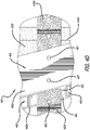
- FIG. 7 is a diagram showing a perspective view of the disclosed space vehicle payload adapter 400 of FIG. 4A comprising circumferential exterior multi-layer insulation (MLI) 710, in accordance with at least one embodiment of the present disclosure.
- the exterior circumference 455 (excluding the secondary payload adapters 720a, 720b, 720c, 720d, 720e, 720f) of the space vehicle payload adapter 400 is covered (e.g., wrapped) with a MLI 710 material, such a MLI 710 blanket.
- MLI 710 is a thermal insulation comprising multiple layers (e.g., six layers) of thin sheets. Wrapping the space vehicle payload adapter 400 with MLI 710 ensures that the space vehicle payload adapter 400 maintains a constant interior temperature despite the extreme temperature fluctuations in space.
- FIG. 8 is a diagram showing a perspective view of secondary satellites (e.g., secondary payloads) 610a, 610b, 610c, 610d, 610e, 610f mounted onto the disclosed space vehicle payload adapter 400 of FIG. 4A comprising circumferential exterior MLI 710, in accordance with at least one embodiment of the present disclosure.
- the MLI 710 blanket is shown to be covering the exterior surface around the circumference of the space vehicle payload adapter 400, except for the portions of the exterior surface comprising the secondary payload adapters.
- FIG. 9 is a flow chart for the disclosed method 900 for reacting loads into a space vehicle payload adapter, in accordance with at least one embodiment of the present disclosure.
- more than two interstitial rings, of the space vehicle payload adapter react the loads, created by secondary payloads mounted onto the space vehicle payload adapter, into a truss structure of the space vehicle payload adapter 920.
- struts of the truss structure react the loads to a forward ring and an aft ring of the space vehicle payload adapter 930.
- the method 900 ends 940.
Landscapes
- Engineering & Computer Science (AREA)
- Remote Sensing (AREA)
- Aviation & Aerospace Engineering (AREA)
- Physics & Mathematics (AREA)
- Astronomy & Astrophysics (AREA)
- General Physics & Mathematics (AREA)
- Connection Of Plates (AREA)
Abstract
Description
- The present disclosure relates to space vehicle payload adapters. In particular, the present disclosure relates to the direct mount of secondary payload adapters to a truss structure common to a space vehicle payload adapter.
- Launch vehicles often employ a space vehicle payload adapter to attach multiple satellites to enable a shared launch for multiple satellites (e.g., a shared launch including a primary satellite along with several small secondary satellites) from the surface of Earth into space. Currently, conventional space vehicle payload adapters often employ a solid monocoque ring design (e.g., refer to the space vehicle
payload adapter ring 100 ofFIG. 1 ). Since this conventional design comprises a solid ring structure, the design is able to provide for stiffness at the interfaces of the secondary payload adapters such that high frequency modes are maintained (e.g., during the duration of the launch). However, the solid ring structure of this conventional design has the disadvantages of being heavy, expensive to manufacture, and not providing for easy access to components located internal to the ring. - In light of the foregoing, there is a need for an improved space vehicle payload adapter design that provides for a reduction in weight and cost, and allows for an easier access to internal components, while also maintaining high frequency modes.
- The present disclosure relates to a method, system, and apparatus for the direct mount of secondary payload adapters to a truss structure common to a space vehicle payload adapter. In one or more embodiments, a method for reacting loads into a space vehicle payload adapter comprises reacting, by more than two interstitial rings of the space vehicle payload adapter, the loads created by secondary payloads mounted onto the space vehicle payload adapter, into a truss structure of the space vehicle payload adapter. The method further comprises reacting, by struts of the truss structure, the loads to a forward ring and an aft ring of the space vehicle payload adapter. In one or more embodiments, the reacting of the loads maintains high frequency (e.g., greater than (>) thirty (30) gigahertz (GHz)) modes for the space vehicle payload adapter.
- In one or more embodiments, the secondary payloads are mounted onto the space vehicle payload adapter via secondary payload adapters. In some embodiments, the secondary payloads are mounted onto the secondary payload adaptors via kinematic mount bolts and/or easy ride adapters. In at least one embodiment, each of the secondary payload adapters are releasably attached to various different locations on at least one of the interstitial rings. In some embodiments, adapter port openings of the secondary payload adapters are of different sizes. In one or more embodiments, each of the adapter port openings comprises one of a circular shape, a rectangular shape, a triangular shape, or a polygon shape. In one or more embodiments, the adapter port openings comprise shapes complementary to interfaces of the secondary payloads. In some embodiments, the secondary payload adapters are manufactured from aluminum, titanium, and/or a composite material.
- In at least one embodiment, the struts connect the forward ring to the aft ring. In one or more embodiments, the struts are oriented at consistent angles to form alternately inverted isosceles triangle-shaped openings within the truss structure.
- In one or more embodiments, the interstitial rings are connected to the struts via a nested joint configuration. In some embodiments, the interstitial rings are located between the forward ring and the aft ring. In at least one embodiment, at least one of the interstitial rings is a partial interstitial ring. In some embodiments, at least one of the interstitial rings comprises a plurality of segments. In one or more embodiments, each of the segments comprises an inner portion and an outer portion.
- In at least one embodiment, the interstitial rings, the struts, the forward ring, and/or the aft ring are manufactured from aluminum, titanium, and/or a composite material.
- In one or more embodiments, a space vehicle payload adapter comprises a forward ring and an aft ring. The space vehicle payload adapter further comprises a truss structure comprising a plurality of struts, where the struts connect the forward ring to the aft ring. Also, the space vehicle payload adapter comprises more than two interstitial rings connected to the struts, and positioned between the forward ring and the aft ring. Further, the space vehicle payload adapter comprises a plurality of secondary payload adapters each releasably attached to at least one of the interstitial rings. In one or more embodiments, the interstitial rings react loads, created by secondary payloads mounted onto the secondary payload adapters, into the truss structure. In at least one embodiment, the struts of the truss structure react the loads to the forward ring and the aft ring. In at least one embodiment, high frequency modes for the space vehicle payload adapter are maintained for the space vehicle payload adapter, when the loads are reacted.
- The features, functions, and advantages can be achieved independently in various embodiments of the present disclosure or may be combined in yet other embodiments.
- These and other features, aspects, and advantages of the present disclosure will become better understood with regard to the following description, appended claims, and accompanying drawings where:
-
FIG. 1 is a diagram showing a perspective view of a conventional space vehicle payload adapter. -
FIG. 2 is a diagram (not to scale) showing an exemplary launch sequence for a spacecraft that employs the disclosed space vehicle payload adapter, in accordance with at least one embodiment of the present disclosure. -
FIG. 3 is a diagram showing details of the disclosed space vehicle payload adapter ofFIG. 2 , in accordance with at least one embodiment of the present disclosure. -
FIG. 4A is a diagram showing a perspective view of the disclosed space vehicle payload adapter, in accordance with at least one embodiment of the present disclosure. -
FIG. 4B is a diagram showing details of a portion of the disclosed space vehicle payload adapter ofFIG. 4A , in accordance with at least one embodiment of the present disclosure. -
FIG. 4C is a diagram showing details of one of the secondary payload adapters of the disclosed space vehicle payload adapter ofFIG. 4A , in accordance with at least one embodiment of the present disclosure. -
FIG. 4D is a diagram showing details of the nested joint design for the interstitial rings of the disclosed space vehicle payload adapter ofFIG. 4A , in accordance with at least one embodiment of the present disclosure. -
FIG. 4E is a diagram showing details of the two-part design for the interstitial rings of the disclosed space vehicle payload adapter ofFIG. 4A , in accordance with at least one embodiment of the present disclosure. -
FIG. 4F is an exploded detailed view of the diagram ofFIG. 4E showing details of the two-part design of the interstitial rings of the disclosed space vehicle payload adapter ofFIG. 4A , in accordance with at least one embodiment of the present disclosure. -
FIG. 5 is a diagram showing a perspective view of the disclosed space vehicle payload adapter ofFIG. 4A , where electronic components are mounted onto the interstitial rings, in accordance with at least one embodiment of the present disclosure. -
FIG. 6 is a diagram showing a perspective view of secondary satellites mounted onto the disclosed space vehicle payload adapter ofFIG. 4A , in accordance with at least one embodiment of the present disclosure. -
FIG. 7 is a diagram showing a perspective view of the disclosed space vehicle payload adapter ofFIG. 4A comprising circumferential exterior multi-layer insulation (MLI), in accordance with at least one embodiment of the present disclosure. -
FIG. 8 is a diagram showing a perspective view of secondary satellites mounted onto the disclosed space vehicle payload adapter ofFIG. 4A comprising circumferential exterior MLI, in accordance with at least one embodiment of the present disclosure. -
FIG. 9 is a flow chart for the disclosed method for reacting loads into a space vehicle payload adapter, in accordance with at least one embodiment of the present disclosure. - The methods and apparatuses disclosed herein provide operative systems for the direct mount of secondary payload adapters to a truss structure common to a space vehicle payload adapter. In one or more embodiments, the system of the present disclosure employs a plurality of interstitial rings within a space vehicle payload adapter, which comprises a lightweight truss structure, to provide stiffness at the interfaces of the secondary payload adapters to maintain high frequency (e.g., greater than (>) thirty (30) gigahertz (GHz)) modes. The disclosed system also employs secondary payload adapters that are clockable to allow for the rotation of the secondary payloads to different locations around the circumference of the space vehicle payload adapter to optimize the center of gravity (CG) for the launch vehicle.
- As previously mentioned above, launch vehicles often employ a space vehicle payload adapter to attach multiple satellites to enable a shared launch for multiple satellites (e.g., a shared launch including a primary satellite (e.g., a primary payload) along with several small secondary satellites (e.g., secondary payloads)) from the surface of Earth into space. Currently, conventional space vehicle payload adapters often employ a solid monocoque ring design (e.g., refer to the space vehicle
payload adapter ring 100 ofFIG. 1 ). Since this conventional design comprises a solid ring structure, the design is able to provide for stiffness at the interfaces of the secondary payload adapters (refer to 110a, 110b, 110c, 110d, 110e, 110f ofFIG. 1 ) such that high frequency modes (e.g., > 30 GHz) are maintained (e.g., during the duration of the launch). However, the solid ring structure of this conventional design has the disadvantages of being heavy, expensive to manufacture, and not providing for easy access to components located internal to the ring. - The system of the present disclosure provides a means to add secondary payloads to a space vehicle payload adapter, which fits between the top of a rocket (e.g., a launch vehicle) and the primary payload, that maintains the high frequency modes of a conventional monocoque ring design, while also utilizing a sparse truss structure that allows for an easier installation of the secondary payloads as well as easy access to internal components (e.g., during payload buildup and test). The disclosed space vehicle payload adapter allows for a reduction in weight and cost as compared to the conventional monocoque ring designs, while maintaining the stiffness at the interfaces of the secondary payload mounts. In particular, the disclosed space vehicle payload adapter employs multiple interstitial rings (e.g., more than two interstitial rings) that interface with the secondary payload adapters as well as with the truss structure. With this disclosed design, the interstitial rings provide a load path to react the bending loads (e.g., loads caused by the secondary payloads) into the truss structure.
- In the following description, numerous details are set forth in order to provide a more thorough description of the system. It will be apparent, however, to one skilled in the art, that the disclosed system may be practiced without these specific details. In the other instances, well known features have not been described in detail, so as not to unnecessarily obscure the system.
- Embodiments of the present disclosure may be described herein in terms of functional and/or logical components and various processing steps. It should be appreciated that such components may be realized by any number of hardware, software, and/or firmware components configured to perform the specified functions. In addition, those skilled in the art will appreciate that embodiments of the present disclosure may be practiced in conjunction with other components, and that the systems described herein are merely example embodiments of the present disclosure.
- For the sake of brevity, conventional techniques and components related to space vehicle payload adapters, and other functional aspects of the system (and the individual operating components of the systems) may not be described in detail herein. Furthermore, the connecting lines shown in the various figures contained herein are intended to represent example functional relationships and/or physical couplings between the various elements. It should be noted that many alternative or additional functional relationships or physical connections may be present in one or more embodiments of the present disclosure.
-
FIG. 1 is a diagram showing a perspective view of a conventional spacevehicle payload adapter 100. In this figure, the conventional spacevehicle payload adapter 100 is shown to comprise a solid monocoque ring design. The conventional space vehicle payload adapter (e.g., referred to as a ring) 100 comprises a single aluminum forging that is machined down to itsflanges vehicle payload adapter 100 inherently defines ashell 130. Theshell 130 of thering 100 carries the stress of any loads exerted upon the spacevehicle payload adapter 100. - It should be noted that, since the secondary payload adapters (e.g., webs) 110a, 110b,110c, 110d, 110e, 110f are machined into the
ring 100, the locations of thesecondary payload adapters ring 100 are fixed. As such, the conventional spacevehicle payload adapter 100 design does not provide the ability to clock (e.g., rotate) the secondary payloads to different locations on theexterior circumference ring 100 to optimize the center of gravity (CG) for the space vehicle (e.g., a launch vehicle combined with the payloads). - In addition, the conventional space
vehicle payload adapter 100 design makes access to the inside of thering 100 very difficult because the interior of thering 100 cannot be accessed from thesecondary payload adapters ring 100, after the secondary payloads are mounted onto thering 100. Additionally, the thickness (e.g., typically around a half an inch) of thesecondary payload adapters -
FIG. 2 is a diagram (not to scale) showing anexemplary launch sequence 200 for a spacecraft (e.g., a primary satellite, referred to as a primary payload) 230 that employs the disclosed spacevehicle payload adapter 210, in accordance with at least one embodiment of the present disclosure. In this figure, theprimary payload 230 as well as a plurality of secondary satellites (e.g., referred to as secondary payloads) 220a, 220b, 220c are mounted onto a launch vehicle (e.g., the launch vehicle upper stage (LVUS)) 240 via the disclosed spacevehicle payload adapter 210. Theprimary payload 230, thesecondary payloads vehicle payload adapter 210 are all initially housed within the payload fairing 295 of the launch vehicle (e.g., LVUS) 240. - At the beginning of the
launch sequence 200, during pre-launch phase of thelaunch sequence 200, a payload van (PVAN) 250 comprising electrical ground support equipment (EGSE) is in communication (e.g., transmitting auxiliary (AUX) payload (PL) telemetry (TLM)) with a spacecraft operations center (SOC) 260 as well as with the launch vehicle (e.g., LVUS) 240. The launch vehicle (e.g., LVUS) 240 is connected to a launch vehicle lower stage (LVLS) 280, and is located on alaunch pad 290 on the ground. - During launch, the
primary payload 230 as well as thesecondary payloads vehicle payload adapter 210 is manufactured and designed to have sufficient stiffness such that high frequency modes (e.g., > 30 GHz) are maintained during all phases of the launch sequence. - During the launch and ascent phase of the
launch sequence 200, theLVLS 280 separates from the launch vehicle (e.g., LVUS) 240, and the payload fairing 295 separates from the launch vehicle (e.g., LVUS) 240. Also during the launch and ascent phase, the launch vehicle (e.g., LVUS) 240 transmits telemetry information to theSOC 260 via aground station antenna 270a. - In one or more embodiments, when the launch vehicle (e.g., LVUS) 240 has reached a lower earth orbit (LEO) or a geostationary transfer orbit (GTO), at least one of the
secondary payloads vehicle payload adapter 210 is deployed into space. Also, when the launch vehicle (e.g., LVUS) 240 has reached a lower earth orbit (LEO) or a geostationary transfer orbit (GTO), the launch vehicle (e.g., LVUS) 240 transmits telemetry information to theSOC 260 via theground station antenna 270a. - Then, the launch vehicle (e.g., LVUS) 240 performs a first trans-launch injection (TLI) maneuver, which is a population maneuver. During the first TLI maneuver, the launch vehicle (e.g., LVUS) 240 transmits telemetry information to the
SOC 260 via aground station antenna 270b. - After the first TLI maneuver, the
primary payload 230 mounted onto the disclosed spacevehicle payload adapter 210 is deployed into space. During the deployment, the launch vehicle (e.g., LVUS) 240 transmits telemetry information to theSOC 260 via theground station antenna 270b. - In one or more embodiments, the launch vehicle (e.g., LVUS) 240 performs a secondary TLI maneuver. During this secondary TLI maneuver, at least one of the
secondary payloads vehicle payload adapter 210 is deployed into space. Also during this secondary TLI maneuver, the launch vehicle (e.g., LVUS) 240 transmits telemetry information to theSOC 260 via aground station antenna 270b. After the secondary TLI maneuver, it is the end of the mission (EoM) for thelaunch sequence 200. - It should be noted that the
launch sequence 200 depicted inFIG. 2 is merely one exemplary launch sequence of phases that may be employed for a spacecraft (e.g., a primary payload) 230 utilizing the disclosed spacevehicle payload adapter 210. As such, in one or more embodiments, launch sequences other than thespecific launch sequence 200 shown inFIG. 2 may be employed by a spacecraft (e.g., a primary payload) 230 utilizing the disclosed spacevehicle payload adapter 210. For example, in one or more embodiments, during the launch sequence, after the spacecraft (e.g., a primary payload) 230 separates from the spacevehicle payload adapter 210, the spacevehicle payload adapter 210 may then separate from the launch vehicle (e.g., LVUS) 240. In another example, during the launch sequence, at least one of thesecondary payloads vehicle payload adapter 210 may be hosted on the spacevehicle payload adapter 210 for the duration of the life of the secondary payload(s) 220a, 220b, 220c. For another example, during the launch sequence, thesecondary payloads vehicle payload adapter 210 into different specific orbital states and/or locations. -
FIG. 3 is a diagram showing details of the disclosed spacevehicle payload adapter 210 ofFIG. 2 , in accordance with at least one embodiment of the present disclosure. In this figure, the spacevehicle payload adapter 210 is located in beneath aprimary payload 230, and is located above a launch vehicle (e.g., LVUS) 240. In particular, theprimary payload 230 is attached (e.g., releasably attached) to aforward ring 450a of the spacevehicle payload adapter 210, and the launch vehicle (e.g., LVUS) 240 is attached to anaft ring 450b of the spacevehicle payload adapter 210. In addition, a plurality ofsecondary payloads vehicle payload adapter 210 viasecondary payload adapters 420. -
FIG. 4A is a diagram showing a perspective view of the disclosed spacevehicle payload adapter 400, in accordance with at least one embodiment of the present disclosure. The spacevehicle payload adapter 400 comprises aforward ring 450a, anaft ring 450b, threeinterstitial rings secondary payload adapters struts 460. It should be noted that, in one or more embodiments, all of the components of the disclosed spacevehicle payload adapter 400 are manufactured from a low cost and lightweight material(s) (e.g., a lightweight metal, such as aluminum or titanium, and/or a composite material). - Employing aluminum (and/or other lightweight material(s)) for the components of the space
vehicle payload adapter 400 allows for the spacevehicle payload adapter 400 to be lightweight and low cost to manufacture. In one or more embodiments, when components of the spacevehicle payload adaptor 400 are manufactured from aluminum, the aluminum components are coated with a conductive Alodine finish to provide for aluminum corrosion protection. It should be noted that although the conventional space vehicle payload adapter (e.g., ring) 100 ofFIG. 1 is also manufactured from aluminum (e.g., a lightweight material), the disclosed spacevehicle payload adapter 400 is much lighter in weight because it employs an open truss structure design as opposed to the conventional solid monocoque ring design (e.g., refer to thering 100 ofFIG. 1 ), which adds a considerable amount of weight. - In
FIG. 4A , the disclosed spacevehicle payload adapter 400 is shown to have an annular profile defining acircumference 455. In one or more embodiments, the spacevehicle payload adapter 400 comprises a forwardopen end 465a defined by theforward ring 450a, and comprises an aftopen end 465b defined by theaft ring 450b. Theforward ring 450a is configured to directly (or indirectly) couple (e.g., releasably attach) the spacevehicle payload adapter 400 to a primary payload (e.g., refer to 230 ofFIG. 3 ). And, theaft ring 450b is configured to directly (or indirectly) couple (e.g., releasably attach) the spacevehicle payload adapter 400 to a launch vehicle (e.g., refer to 240 ofFIG. 3 ). - In one or more embodiments, the
forward ring 450a and theaft ring 450b have the same diameter (D), as is shown inFIG. 4A . However, in other embodiments, theforward ring 450a and theaft ring 450b may have different diameters. For example, theforward ring 450a may have a first diameter (D1) and theaft ring 450b may have a second diameter (D2), where the first diameter (D1) is larger than (or, alternatively, smaller than) the second diameter (D2). The specific diameters of theforward ring 450a and theaft ring 450b of the spacevehicle payload adapter 400 are determined based on the packaging requirements of the payload fairing of the launch vehicle (e.g., refer to the payload fairing 295 of theLVUS 240 ofFIG. 2 ). - The space
vehicle payload adapter 400 also comprises an open truss structure comprising a plurality ofstruts 460 connecting theforward ring 450a to theaft ring 450b and, as such, each of thestruts 460 extends from theforward ring 450a to theaft ring 450b. In particular, a first end of each of thestruts 460 is connected to theforward ring 450a, and a second end of each of thestruts 460 is connected to theaft ring 450b. In one or more embodiments, thestruts 460 are oriented at consistent angles to form alternately inverted isosceles triangle-shapedopenings 475 around thecircumference 455 of the spacevehicle payload adapter 400. This specific arrangement of thestruts 460 in the open truss structure of the spacevehicle payload adapter 400 is referred to in structural engineering as a "Warren truss" or an "equilateral truss". - In addition, the space
vehicle payload adapter 400 comprises sixsecondary payload adapters circumference 455 of the spacevehicle payload adapter 400. Thesecondary payload adapters FIG. 6 ) onto the spacevehicle payload adapter 400. In one or more embodiments, the spacevehicle payload adapter 400 may comprise more (or, alternatively, less) than sixsecondary payload adapters FIG. 4A . - In one or more embodiments, the
secondary payload adapters secondary payload adapters secondary payload adapters FIG. 4A ,secondary payload adapters secondary payload adapters - It should be noted that, in one or more embodiments, more (or, alternatively, less) than two different sizes (and/or weights) of
secondary payload adapters vehicle payload adapter 400. In addition, in one or more embodiments, thesecondary payload adapters FIG. 4A . As such, the shapes (as well as the sizes) of the adaptor port openings of thesecondary payload adaptors FIG. 6 ) to be attached to the spacevehicle payload adaptor 400. Thus, the adapter port openings of thesecondary payload adapters - In addition, the
secondary payload adapters FIG. 6 ) via fasteners (e.g., bolts, such as kinematic mount bolts or easy ride adapters). InFIG. 4A , the bolt hole pattern on each of thesecondary payload adapters secondary payload adapters FIG. 4A . The shapes (as well as the sizes) of the bolt hole patterns of thesecondary payload adaptors FIG. 6 ). Also, it should be noted that, inFIG. 4A , each of thesecondary payload adapters secondary payload adapters FIG. 4A . - Additionally, each of the
secondary payload adapters interstitial rings vehicle payload adapter 400. The threeinterstitial rings circumference 455. And, thesecondary payload adapters fixtures 485 of theinterstitial rings secondary payload adapters FIG. 4A , thesecondary payload adapters interstitial rings FIG. 4B ) disposed within the mountingfixtures 485 of theinterstitial rings secondary payload adapters FIG. 4B for details of the attaching ofsecondary payload adapter 420a tointerstitial ring 430a via removable fasteners (e.g., bolts) 497. - However, it should be noted that, the use of fasteners (e.g., bolts) for the attaching of the
secondary payload adapters secondary payload adapters vehicle payload adapter 400. As such, in one or more embodiments, thesecondary payload adapters interstitial rings FIG. 4A . - In one or more embodiments, the
secondary payload adapters vehicle payload adapter 400 to balance the center of gravity of the launch vehicle. For example, at least one of thesecondary payload adapters circumference 455 of the spacevehicle payload adapter 400 and, then, attached to another location on thecircumference 455 of the spacevehicle payload adapter 400. In particular, one of thesecondary payload adapters interstitial rings secondary payload adapter interstitial rings - It should be noted that the center of gravity of the launch vehicle should be balanced to ensure controllability during launch. If the secondary payloads (e.g., refer to 610a, 610b, 610c, 610d, 610e, 610f of
FIG. 6 ) are not of equal size (volume) and/or mass, and/or are attached to the payload adapter in a non-symmetrical manner, then the center of gravity of the launch vehicle may exceed the controllable offset limit. As a result, a ballast may be required to provide balance to the launch vehicle. However, introducing a ballast reduces the amount of usable payload mass that the launch vehicle can carry. - Each of the
interstitial rings vehicle payload adapter 400 is attached to thestruts 460 of the open truss structure of the spacevehicle payload adapter 400. Each of thestruts 460 comprises a plurality of mounting apertures 487 (e.g., in the form of bolt holes) each configurable to receive a fastener (e.g., a bolt). The mountingfixtures 485 of theinterstitial rings struts 460. Also, each of thestruts 460 comprises at least one V-shaped joint (e.g., refer to 492 ofFIG. 4D ), which comprises a first portion (e.g., refer to 482a ofFIG. 4D ) and a second portion (e.g., refer to 482b ofFIG. 4D ), configured to receive one of theinterstitial rings - For example, for the attaching of an
interstitial ring 430b (refer toFIG. 4D ) to astrut 460, theinterstitial ring 430b is disposed within the V-shaped joint (e.g., refer to 492 ofFIG. 4D ) of thestrut 460, thereby forming a nested joint. Specifically, theinterstitial ring 430b slides between the first portion (e.g., refer to 482a ofFIG. 4D ) and the second portion (e.g., refer to 482b ofFIG. 4D ) of the V-shaped joint (e.g., refer to 492 ofFIG. 4D ) of thestrut 460. After theinterstitial ring 430b is disposed within the V-shaped joint (e.g., refer to 492 ofFIG. 4D ) of thestrut 460, thestrut 460 is attached to theinterstitial ring 430b via fasteners (e.g., bolts) disposed within the mountingapertures 487 of thestrut 460 and within the mountingfixtures 485 of theinterstitial ring 430b. Refer toFIG. 4D for details of the attaching of astrut 460 to aninterstitial ring 430b. - It is important to note that the
interstitial rings vehicle payload adapter 400 to provide sufficient stiffness to the spacevehicle payload adapter 400 such that high frequency modes (e.g., > 30 GHz) are always maintained during all aspects of launch (e.g., during all of the phases of the launch sequence). During launch, theprimary payload 230 as well as thesecondary payloads secondary payloads secondary payload adapters secondary payload adapters struts 460 of the open truss structure. Thestruts 460 then react the loads to theforward ring 450a andaft ring 450b and, as a result, high frequency modes are maintained for the spacevehicle payload adapter 400. - It should be noted that in one or more embodiments, the disclosed space
vehicle payload adapter 400 comprises more than two fullinterstitial rings interstitial rings vehicle payload adapter 400, high frequency modes are able to be maintained for the spacevehicle payload adapter 400. And, in one or more embodiments, at least one of theinterstitial rings vehicle payload adapter 400 may be merely a partialinterstitial ring interstitial ring interstitial ring -
FIG. 4B is a diagram showing details of aportion 410 of the disclosed spacevehicle payload adapter 400 ofFIG. 4A , in accordance with at least one embodiment of the present disclosure. In particular, the diagram ofFIG. 4B shows details of aportion 410 inFIG. 4A depicting the releasable attachment ofsecondary payload adapter 420a tointerstitial ring 430a. In particular, in this figure, thesecondary payload adapter 420a is shown to be releasably attached tointerstitial ring 430a via removable fasteners (e.g., bolts) 497 disposed within the mountingfixtures 485 of theinterstitial ring 430a and within the attachment points 495 of thesecondary payload adapter 420a. -
FIG. 4C is a diagram showing details of one of thesecondary payload adapters 420a of the disclosed spacevehicle payload adapter 400 ofFIG. 4A , in accordance with at least one embodiment of the present disclosure. In particular, in this figure, details of the releasable attachment ofsecondary payload adapter 420a to all threeinterstitial rings -
FIG. 4D is a diagram showing details of the nested joint design for the interstitial rings (e.g.,interstitial ring 430b) of the disclosed spacevehicle payload adapter 400 ofFIG. 4A , in accordance with at least one embodiment of the present disclosure. In particular, the diagram ofFIG. 4D shows details of the interior side (e.g., the back side not visible inFIG. 4C ) of theportion 490 denoted inFIG. 4C . InFIG. 4D ,interstitial ring 430b is shown to be attached to astrut 460. For the attaching, theinterstitial ring 430b is disposed between thefirst portion 482a and thesecond portion 482b of the V-shapedjoint 492 of thestrut 460, resulting in a nested joint configuration. Then, thestrut 460 is attached to theinterstitial ring 430b via fasteners (e.g., bolts) (not shown inFIG. 4D ) disposed within the mountingapertures 487 of thestrut 460 and within the mountingfixtures 485 of theinterstitial ring 430b. -
FIG. 4E is a diagram showing details of the two-part design for theinterstitial rings vehicle payload adapter 400 ofFIG. 4A , in accordance with at least one embodiment of the present disclosure. And,FIG. 4F is an exploded detailed view of the diagram ofFIG. 4E showing details of the two-part design (e.g., showing the inner portions (I) and outer portions (O)) of theinterstitial rings vehicle payload adapter 400 ofFIG. 4A , in accordance with at least one embodiment of the present disclosure. - It should be noted that the two-part design shown in
FIGS. 4E and4F may be used in conjunction with (or, alternatively, used without) the nested joint design shown inFIG. 4D for the disclosedinterstitial rings FIG. 4D may be used in conjunction with (or, alternatively, used without) the two-part design shown inFIGS. 4E and4F for the disclosedinterstitial rings FIGS. 4D ,4E , and4F are merely exemplary designs for the nested joint design and the two-part design for the disclosed interstitial rings and, as such, in one or more embodiments, variations and modifications to these designs may be made without departing from the scope of the disclosure. - In one or more embodiments, for the two-part design shown in
FIGS. 4E and4F , each of theinterstitial rings interstitial ring FIG. 4F ,interstitial ring 430c is shown to comprise multiple segments, such as a first segment (1) and a second segment (2). And, each segment (1), (2) is shown to comprise an inner portion (I) and an outer portion (O). As such, in the exploded view ofFIG. 4E ,interstitial ring 430c is shown to comprise 430c(1)(O) (i.e. segment (1), outer portion (O)); 430c(1)(I) (i.e. segment (1), inner portion (I)); 430c(2)(O) (i.e., segment (2), outer portion (O)); and 430c(2)(I) (i.e. segment (2), inner portion (I)). The outer portions (O) of each of the segments (1), (2), (3), (4), (5), and (6) are attached to their corresponding inner portions (I) via at least one fastener (e.g., bolt) 472. For example, with regard to segment (1) ofinterstitial ring -
FIG. 5 is a diagram showing a perspective view of the disclosed spacevehicle payload adapter 400 ofFIG. 4A , whereelectronic components interstitial rings electrical components interstitial rings interstitial rings vehicle payload adapter 400 including, but not limited to, a power source (e.g., a battery), a propulsion and mechanism module (PAM), and an embedded relay module (ERM). - It should be noted that in one or more embodiments, the interstitial rings 430a, 430b, 430c comprise wiring holes (e.g., refer to 470 in
FIGS. 4B ,4E , and4F ) to provide pathways for routing wiring from theelectrical components struts 460. As such, wiring connected to theelectrical components -
FIG. 6 is a diagram showing a perspective view of secondary satellites (e.g., secondary payloads) 610a, 610b, 610c, 610d, 610e, 610f mounted onto the disclosed spacevehicle payload adapter 400 ofFIG. 4A , in accordance with at least one embodiment of the present disclosure. In this figure, thesecondary payloads vehicle payload adapter 400 are of unequal size (volume) and mass. In particular,secondary payloads secondary payloads FIG. 6 is merely exemplary in nature and that any number and composition ofsecondary payloads vehicle payload adapter 400. In addition, it should be noted that althoughFIG. 6 shows thesecondary payloads secondary payloads vehicle payload adapter 400 may vary. -
FIG. 7 is a diagram showing a perspective view of the disclosed spacevehicle payload adapter 400 ofFIG. 4A comprising circumferential exterior multi-layer insulation (MLI) 710, in accordance with at least one embodiment of the present disclosure. In this figure, the exterior circumference 455 (excluding thesecondary payload adapters vehicle payload adapter 400 is covered (e.g., wrapped) with aMLI 710 material, such aMLI 710 blanket.MLI 710 is a thermal insulation comprising multiple layers (e.g., six layers) of thin sheets. Wrapping the spacevehicle payload adapter 400 withMLI 710 ensures that the spacevehicle payload adapter 400 maintains a constant interior temperature despite the extreme temperature fluctuations in space. -
FIG. 8 is a diagram showing a perspective view of secondary satellites (e.g., secondary payloads) 610a, 610b, 610c, 610d, 610e, 610f mounted onto the disclosed spacevehicle payload adapter 400 ofFIG. 4A comprisingcircumferential exterior MLI 710, in accordance with at least one embodiment of the present disclosure. In this figure, theMLI 710 blanket is shown to be covering the exterior surface around the circumference of the spacevehicle payload adapter 400, except for the portions of the exterior surface comprising the secondary payload adapters. -
FIG. 9 is a flow chart for the disclosed method 900 for reacting loads into a space vehicle payload adapter, in accordance with at least one embodiment of the present disclosure. At thestart 910 of the method 900, more than two interstitial rings, of the space vehicle payload adapter, react the loads, created by secondary payloads mounted onto the space vehicle payload adapter, into a truss structure of the spacevehicle payload adapter 920. Then, struts of the truss structure, react the loads to a forward ring and an aft ring of the spacevehicle payload adapter 930. Then, the method 900 ends 940. - Although particular embodiments have been shown and described, it should be understood that the above discussion is not intended to limit the scope of these embodiments. While embodiments and variations of the many aspects of the disclosure have been disclosed and described herein, such disclosure is provided for purposes of explanation and illustration only. Thus, various changes and modifications may be made without departing from the scope of the claims.
- Where methods described above indicate certain events occurring in certain order, those of ordinary skill in the art having the benefit of this disclosure would recognize that the ordering may be modified and that such modifications are in accordance with the variations of the present disclosure. Additionally, parts of methods may be performed concurrently in a parallel process when possible, as well as performed sequentially. In addition, more steps or less steps of the methods may be performed. Accordingly, embodiments are intended to exemplify alternatives, modifications, and equivalents that may fall within the scope of the claims.
- Further, the disclosure comprises embodiments according to the following clauses:
-
Clause 1. A method for reacting loads into a space vehicle payload adapter, the method comprising:- reacting, by more than two interstitial rings of the space vehicle payload adapter), the loads created by secondary payloads mounted onto the space vehicle payload adapter, into a truss structure of the space vehicle payload adapter; and
- reacting, by struts of the truss structure, the loads to a forward ring and an aft ring of the space vehicle payload adapter.
-
Clause 2. The method ofClause 1, wherein the reacting of the loads maintains high frequency modes for the space vehicle payload adapter. - Clause 3. The method of
Clause 1 orclause 2, wherein the secondary payloads are mounted onto the space vehicle payload adapter via secondary payload adapters. - Clause 4. The method of Clause 3, wherein the secondary payloads are mounted onto the secondary payload adaptors via at least one of kinematic mount bolts or easy ride adapters.
- Clause 5. The method of Clause 3 or Clause 4, wherein each of the secondary payload adapters are releasably attached to various different locations on at least one of the interstitial rings.
- Clause 6. The method of any of Clauses 3-5, wherein adapter port openings of the secondary payload adapters are of different sizes.
- Clause 7. The method of any of Clauses 3-6, wherein adapter port openings of the secondary payload adaptors comprise shapes complementary to interfaces of the secondary payloads.
- Clause 8. The method of any of Clauses 3-7, wherein the secondary payload adapters are manufactured from at least one of aluminum, titanium, or a composite material.
- Clause 9. The method of any preceding Clause, wherein the struts connect the forward ring to the aft ring.
-
Clause 10. The method of any preceding Clause, wherein the struts are oriented at consistent angles to form alternately inverted isosceles triangle-shaped openings within the truss structure. - Clause 11. The method of any preceding Clause, wherein the interstitial rings are connected to the struts via a nested joint configuration.
- Clause 12. The method of any preceding Clause, wherein the interstitial rings are located between the forward ring and the aft ring).
- Clause 13. The method of any preceding Clause, wherein at least one of the interstitial rings is a partial interstitial ring.
- Clause 14. The method of any preceding Clause, wherein at least one of the interstitial rings comprises a plurality of segments.
- Clause 15. The method of Clause 14, wherein each of the segments comprises an inner portion and an outer portion.
- Clause 16. The method of any preceding Clause, wherein at least one of the interstitial rings, the struts, the forward ring), or the aft ring are manufactured from at least one of aluminum, titanium, or a composite material.
- Clause 17. A space vehicle payload adapter, the space vehicle payload adapter comprising:
- a forward ring;
an aft ring; - a truss structure comprising a plurality of struts, wherein the struts connect the forward ring to the aft ring;
- more than two interstitial rings connected to the struts, and positioned between the forward ring and the aft ring; and
- a plurality of secondary payload adapters each releasably attached to at least one of the interstitial rings,
- wherein the interstitial rings react loads, created by secondary payloads mounted onto the secondary payload adapters, into the truss structure, and
- wherein the struts of the truss structure react the loads to the forward ring (450a) and the aft ring.
- a forward ring;
- Clause 18. The space vehicle payload adapter of Clause 17, wherein high frequency modes for the space vehicle payload adapter are maintained for the space vehicle payload adapter, when the loads are reacted.
- Clause 19. The space vehicle payload adapter of Clause 17 or Clause 18, wherein the interstitial rings are connected to the struts via a nested joint configuration.
- Clause 20. The space vehicle payload adapter of any of Clauses 17-19, wherein at least one of the interstitial rings comprises a plurality of segments.
- Although certain illustrative embodiments and methods have been disclosed herein, it can be apparent from the foregoing disclosure to those skilled in the art that variations and modifications of such embodiments and methods can be made without departing from the true scope of this disclosure. Many other examples exist, each differing from others in matters of detail only. Accordingly, it is intended that this disclosure be limited only to the extent required by the appended claims and the rules and principles of applicable law.
Claims (15)
- A method for reacting loads into a space vehicle payload adapter (400), the method comprising:reacting (920), by more than two interstitial rings (430a, 430b, 430c) of the space vehicle payload adapter (400), the loads created by secondary payloads (220a, 220b, 220c) mounted onto the space vehicle payload adapter (400), into a truss structure of the space vehicle payload adapter (400); andreacting (930), by struts (460) of the truss structure, the loads to a forward ring (450a) and an aft ring (450b) of the space vehicle payload adapter (400).
- The method of claim 1, wherein the reacting of the loads maintains high frequency modes for the space vehicle payload adapter (400).
- The method of claims 1 or 2, wherein the secondary payloads (220a, 220b, 220c) are mounted onto the space vehicle payload adapter (400) via secondary payload adapters (420a, 420b, 420c, 420d, 420e, 420f).
- The method of claim 3, wherein the secondary payloads (220a, 220b, 220c) are mounted onto the secondary payload adaptors (420a, 420b, 420c, 420d, 420e, 420f) via at least one of kinematic mount bolts or easy ride adapters.
- The method of claims 3 or 4, wherein each of the secondary payload adapters (420a, 420b, 420c, 420d, 420e, 420f) are releasably attached to various different locations on at least one of the interstitial rings (430a, 430b, 430c).
- The method of any one of claims 3-5, wherein adapter port openings of the secondary payload adapters (420a, 420b, 420c, 420d, 420e, 420f) are of different sizes.
- The method of any one of claims 3-6, wherein adapter port openings of the secondary payload adaptors (420a, 420b, 420c, 420d, 420e, 420f) comprise shapes complementary to interfaces of the secondary payloads (220a, 220b, 220c).
- The method of any one of claims 3-7, wherein the secondary payload adapters (420a, 420b, 420c, 420d, 420e, 420f) are manufactured from at least one of aluminum, titanium, or a composite material.
- The method of any one of claims 1-8, wherein the struts (460) connect the forward ring (450a) to the aft ring (450b).
- The method of any one of claims 1-9, wherein the struts (460) are oriented at consistent angles to form alternately inverted isosceles triangle-shaped openings within the truss structure.
- The method of any one of claims 1-10, wherein the interstitial rings (430a, 430b, 430c) are connected to the struts (460) via a nested joint configuration.
- The method of any one of claims 1-11, wherein the interstitial rings (430a, 430b, 430c) are located between the forward ring (450a) and the aft ring (450b).
- The method of any one of claims 1-12, wherein at least one of the interstitial rings (430a, 430b, 430c) is a partial interstitial ring.
- The method of any one of claims 1-13, wherein at least one of the interstitial rings (430a, 430b, 430c) comprises a plurality of segments (430c(1), 430c(2)).
- The method of claim 14, wherein each of the segments (430c(1), 430c(2)) comprises an inner portion (430c(1)(I), 430c(2)(I)) and an outer portion (430c(1)(O), 430c(2)(O)).
Priority Applications (1)
| Application Number | Priority Date | Filing Date | Title |
|---|---|---|---|
| EP24154597.9A EP4339108B1 (en) | 2021-02-03 | 2022-01-31 | Direct mount of secondary payload adapters to truss structure common to space vehicle payload adapter |
Applications Claiming Priority (1)
| Application Number | Priority Date | Filing Date | Title |
|---|---|---|---|
| US202163145331P | 2021-02-03 | 2021-02-03 |
Related Child Applications (2)
| Application Number | Title | Priority Date | Filing Date |
|---|---|---|---|
| EP24154597.9A Division EP4339108B1 (en) | 2021-02-03 | 2022-01-31 | Direct mount of secondary payload adapters to truss structure common to space vehicle payload adapter |
| EP24154597.9A Division-Into EP4339108B1 (en) | 2021-02-03 | 2022-01-31 | Direct mount of secondary payload adapters to truss structure common to space vehicle payload adapter |
Publications (2)
| Publication Number | Publication Date |
|---|---|
| EP4039598A1 true EP4039598A1 (en) | 2022-08-10 |
| EP4039598B1 EP4039598B1 (en) | 2025-04-16 |
Family
ID=80123414
Family Applications (2)
| Application Number | Title | Priority Date | Filing Date |
|---|---|---|---|
| EP24154597.9A Active EP4339108B1 (en) | 2021-02-03 | 2022-01-31 | Direct mount of secondary payload adapters to truss structure common to space vehicle payload adapter |
| EP22154183.2A Active EP4039598B1 (en) | 2021-02-03 | 2022-01-31 | Direct mount of secondary payload adapters to truss structure common to space vehicle payload adapter |
Family Applications Before (1)
| Application Number | Title | Priority Date | Filing Date |
|---|---|---|---|
| EP24154597.9A Active EP4339108B1 (en) | 2021-02-03 | 2022-01-31 | Direct mount of secondary payload adapters to truss structure common to space vehicle payload adapter |
Country Status (3)
| Country | Link |
|---|---|
| US (1) | US11827385B2 (en) |
| EP (2) | EP4339108B1 (en) |
| CN (1) | CN114852373A (en) |
Families Citing this family (3)
| Publication number | Priority date | Publication date | Assignee | Title |
|---|---|---|---|---|
| US12354777B2 (en) * | 2021-10-04 | 2025-07-08 | The Aerospace Corporation | Integrated electro-magnetically preloaded kinematic joint for on-orbit assembly of modular space vehicles |
| FR3131907A1 (en) * | 2022-01-14 | 2023-07-21 | Arianegroup Sas | Orbital deployment module with a three-point space propulsion system |
| US20240239522A1 (en) * | 2023-01-12 | 2024-07-18 | Spaceflight Inc. | Systems and apparatus for a configurable annex base (cab) on an orbital transfer vehicle (otv) for payload rideshare missions |
Citations (5)
| Publication number | Priority date | Publication date | Assignee | Title |
|---|---|---|---|---|
| US20080078886A1 (en) * | 2006-08-22 | 2008-04-03 | The Boeing Company | Launch vehicle cargo carrier |
| WO2008147461A1 (en) * | 2006-12-11 | 2008-12-04 | Michael David Johnson | Modular spacecraft |
| US8393582B1 (en) * | 2010-10-12 | 2013-03-12 | United Launch Alliance, L.L.C. | Apparatus and method of transferring and utilizing residual fuel of a launch vehicle upper stage |
| EP2990686A1 (en) * | 2014-08-27 | 2016-03-02 | RUAG Space AB | Shock damping element |
| RU2725824C1 (en) * | 2020-01-10 | 2020-07-06 | Акционерное общество "Научно-производственное объединение им. С.А. Лавочкина" | Device for group launch of satellites and reinforced frame |
Family Cites Families (12)
| Publication number | Priority date | Publication date | Assignee | Title |
|---|---|---|---|---|
| US5560102A (en) * | 1992-10-13 | 1996-10-01 | The Boeing Company | Panel and fuselage assembly |
| US6138951A (en) * | 1998-08-10 | 2000-10-31 | Mcdonnell Douglas Corporation | Spacecraft dispensing system |
| US6793183B1 (en) * | 2003-04-10 | 2004-09-21 | The Boeing Company | Integral node tubular spaceframe |
| US7222823B2 (en) * | 2004-07-06 | 2007-05-29 | Ata Engineering, Inc. | Payload adapter |
| US7434767B2 (en) * | 2005-02-28 | 2008-10-14 | The Boeing Company | Spacecraft adapter having embedded resources, and methods of forming same |
| US20170036782A1 (en) * | 2013-11-19 | 2017-02-09 | Arthur Dula | Launch apparatus |
| CN204776080U (en) * | 2015-06-01 | 2015-11-18 | 上海宇航系统工程研究所 | Double star parallels emitter of asymmetric overall arrangement |
| RU2624959C1 (en) * | 2016-04-28 | 2017-07-11 | Акционерное общество "Научно-производственное объединение им. С.А.Лавочкина" | Adapter for way loose of useful load |
| CN106382861B (en) * | 2016-11-23 | 2018-04-06 | 上海宇航系统工程研究所 | A kind of carrier rocket installs the supporting cabin side wall carrying structure of hundred feather weight satellites |
| CN110104215B (en) * | 2019-04-28 | 2022-07-12 | 上海宇航系统工程研究所 | Space truss type multi-star adapter |
| US11396389B2 (en) | 2019-11-08 | 2022-07-26 | The Boeing Company | Payload adapter having a truss support structure |
| US11565834B2 (en) | 2019-11-08 | 2023-01-31 | The Boeing Company | Clockable secondary payload bridges for a payload adapter |
-
2022
- 2022-01-18 US US17/648,225 patent/US11827385B2/en active Active
- 2022-01-29 CN CN202210111378.3A patent/CN114852373A/en active Pending
- 2022-01-31 EP EP24154597.9A patent/EP4339108B1/en active Active
- 2022-01-31 EP EP22154183.2A patent/EP4039598B1/en active Active
Patent Citations (5)
| Publication number | Priority date | Publication date | Assignee | Title |
|---|---|---|---|---|
| US20080078886A1 (en) * | 2006-08-22 | 2008-04-03 | The Boeing Company | Launch vehicle cargo carrier |
| WO2008147461A1 (en) * | 2006-12-11 | 2008-12-04 | Michael David Johnson | Modular spacecraft |
| US8393582B1 (en) * | 2010-10-12 | 2013-03-12 | United Launch Alliance, L.L.C. | Apparatus and method of transferring and utilizing residual fuel of a launch vehicle upper stage |
| EP2990686A1 (en) * | 2014-08-27 | 2016-03-02 | RUAG Space AB | Shock damping element |
| RU2725824C1 (en) * | 2020-01-10 | 2020-07-06 | Акционерное общество "Научно-производственное объединение им. С.А. Лавочкина" | Device for group launch of satellites and reinforced frame |
Also Published As
| Publication number | Publication date |
|---|---|
| EP4339108A3 (en) | 2024-05-29 |
| EP4339108A2 (en) | 2024-03-20 |
| EP4039598B1 (en) | 2025-04-16 |
| EP4339108B1 (en) | 2025-04-16 |
| US20220242596A1 (en) | 2022-08-04 |
| US11827385B2 (en) | 2023-11-28 |
| CN114852373A (en) | 2022-08-05 |
Similar Documents
| Publication | Publication Date | Title |
|---|---|---|
| EP4039598A1 (en) | Direct mount of secondary payload adapters to truss structure common to space vehicle payload adapter | |
| US7905453B2 (en) | Piggyback equipment panel payload arrangement, a device for and method of attaching a hosted secondary piggyback payload and adapter to be used for a piggyback secondary payload arrangement for launching the piggyback equipment panel secondary | |
| US8789797B2 (en) | Payload adapters including antenna assemblies, satellite assemblies and related systems and methods | |
| CN108349596B (en) | Payload Distribution System | |
| CN112389677A (en) | Satellite dispenser and method of supporting a plurality of satellites | |
| US7866607B2 (en) | Piggyback satellite payload arrangement, a device for and method of attaching a piggyback satellite payload and adapter to be used for a piggyback satellite payload arrangement for launching the piggyback satellite | |
| CN103930348B (en) | Propulsion bay | |
| EP2407384B1 (en) | Dual evolved expendable launch vehicle (EELV) secondary payload adaptor (ESPA) port small satellite design | |
| EP4015398A1 (en) | Stacked satellite assemblies and related methods | |
| US9796484B2 (en) | Satellite system comprising two satellites attached to each other and method for launching them into orbit | |
| EP3385173B1 (en) | A spacecraft, a system and a method for deploying a spacecraft | |
| US20160046397A1 (en) | Multiple space vehicle launch system | |
| EP3717358A1 (en) | Flexible satellite for deployment from attachment hub | |
| CN103847982A (en) | Method and apparatus for performing propulsion operations using an electric propulsion system | |
| JPH0655597B2 (en) | Transport aircraft | |
| US20050109878A1 (en) | Spacecraft and method for building such a spacecraft and an adapter to be used in such a spacecraft | |
| CN210942315U (en) | launch vehicle fairing | |
| US20210347504A1 (en) | Spacecraft systems and methods | |
| EP1492706B1 (en) | Spacecraft, method for building such a spacecraft, and adaptor to be used in such a spacecraft | |
| EP3392155B1 (en) | Payload adapter ring | |
| Hoffman et al. | Preliminary Design of the Cruise, Entry, Descent, and Landing Mechanical Subsystem for MSL | |
| Seversike | Iowa Satellite Project | |
| Mosier et al. | Pegasus: Key to Low-Cost Space Applications | |
| Fleisig | Shuttle demonstration of large space structure fabrication and assembly | |
| Whisnant et al. | Orbital Deployment of Very Long Tethered Structures |
Legal Events
| Date | Code | Title | Description |
|---|---|---|---|
| PUAI | Public reference made under article 153(3) epc to a published international application that has entered the european phase |
Free format text: ORIGINAL CODE: 0009012 |
|
| STAA | Information on the status of an ep patent application or granted ep patent |
Free format text: STATUS: THE APPLICATION HAS BEEN PUBLISHED |
|
| AK | Designated contracting states |
Kind code of ref document: A1 Designated state(s): AL AT BE BG CH CY CZ DE DK EE ES FI FR GB GR HR HU IE IS IT LI LT LU LV MC MK MT NL NO PL PT RO RS SE SI SK SM TR |
|
| STAA | Information on the status of an ep patent application or granted ep patent |
Free format text: STATUS: REQUEST FOR EXAMINATION WAS MADE |
|
| 17P | Request for examination filed |
Effective date: 20221219 |
|
| RBV | Designated contracting states (corrected) |
Designated state(s): AL AT BE BG CH CY CZ DE DK EE ES FI FR GB GR HR HU IE IS IT LI LT LU LV MC MK MT NL NO PL PT RO RS SE SI SK SM TR |
|
| RAP3 | Party data changed (applicant data changed or rights of an application transferred) |
Owner name: THE BOEING COMPANY |
|
| GRAP | Despatch of communication of intention to grant a patent |
Free format text: ORIGINAL CODE: EPIDOSNIGR1 |
|
| STAA | Information on the status of an ep patent application or granted ep patent |
Free format text: STATUS: GRANT OF PATENT IS INTENDED |
|
| RIC1 | Information provided on ipc code assigned before grant |
Ipc: B64G 1/64 20060101AFI20231004BHEP |
|
| INTG | Intention to grant announced |
Effective date: 20231027 |
|
| GRAJ | Information related to disapproval of communication of intention to grant by the applicant or resumption of examination proceedings by the epo deleted |
Free format text: ORIGINAL CODE: EPIDOSDIGR1 |
|
| STAA | Information on the status of an ep patent application or granted ep patent |
Free format text: STATUS: REQUEST FOR EXAMINATION WAS MADE |
|
| STAA | Information on the status of an ep patent application or granted ep patent |
Free format text: STATUS: EXAMINATION IS IN PROGRESS |
|
| 17Q | First examination report despatched |
Effective date: 20240305 |
|
| INTC | Intention to grant announced (deleted) | ||
| P01 | Opt-out of the competence of the unified patent court (upc) registered |
Effective date: 20240229 |
|
| GRAP | Despatch of communication of intention to grant a patent |
Free format text: ORIGINAL CODE: EPIDOSNIGR1 |
|
| STAA | Information on the status of an ep patent application or granted ep patent |
Free format text: STATUS: GRANT OF PATENT IS INTENDED |
|
| GRAS | Grant fee paid |
Free format text: ORIGINAL CODE: EPIDOSNIGR3 |
|
| GRAA | (expected) grant |
Free format text: ORIGINAL CODE: 0009210 |
|
| STAA | Information on the status of an ep patent application or granted ep patent |
Free format text: STATUS: THE PATENT HAS BEEN GRANTED |
|
| INTG | Intention to grant announced |
Effective date: 20250213 |
|
| AK | Designated contracting states |
Kind code of ref document: B1 Designated state(s): AL AT BE BG CH CY CZ DE DK EE ES FI FR GB GR HR HU IE IS IT LI LT LU LV MC MK MT NL NO PL PT RO RS SE SI SK SM TR |
|
| REG | Reference to a national code |
Ref country code: GB Ref legal event code: FG4D |
|
| REG | Reference to a national code |
Ref country code: CH Ref legal event code: EP Ref country code: DE Ref legal event code: R096 Ref document number: 602022013083 Country of ref document: DE |
|
| REG | Reference to a national code |
Ref country code: IE Ref legal event code: FG4D |
|
| REG | Reference to a national code |
Ref country code: NL Ref legal event code: MP Effective date: 20250416 |
|
| PG25 | Lapsed in a contracting state [announced via postgrant information from national office to epo] |
Ref country code: NL Free format text: LAPSE BECAUSE OF FAILURE TO SUBMIT A TRANSLATION OF THE DESCRIPTION OR TO PAY THE FEE WITHIN THE PRESCRIBED TIME-LIMIT Effective date: 20250416 |
|
| REG | Reference to a national code |
Ref country code: AT Ref legal event code: MK05 Ref document number: 1785491 Country of ref document: AT Kind code of ref document: T Effective date: 20250416 |
|
| PG25 | Lapsed in a contracting state [announced via postgrant information from national office to epo] |
Ref country code: FI Free format text: LAPSE BECAUSE OF FAILURE TO SUBMIT A TRANSLATION OF THE DESCRIPTION OR TO PAY THE FEE WITHIN THE PRESCRIBED TIME-LIMIT Effective date: 20250416 Ref country code: PT Free format text: LAPSE BECAUSE OF FAILURE TO SUBMIT A TRANSLATION OF THE DESCRIPTION OR TO PAY THE FEE WITHIN THE PRESCRIBED TIME-LIMIT Effective date: 20250818 Ref country code: ES Free format text: LAPSE BECAUSE OF FAILURE TO SUBMIT A TRANSLATION OF THE DESCRIPTION OR TO PAY THE FEE WITHIN THE PRESCRIBED TIME-LIMIT Effective date: 20250416 |
|
| REG | Reference to a national code |
Ref country code: LT Ref legal event code: MG9D |
|
| PG25 | Lapsed in a contracting state [announced via postgrant information from national office to epo] |
Ref country code: GR Free format text: LAPSE BECAUSE OF FAILURE TO SUBMIT A TRANSLATION OF THE DESCRIPTION OR TO PAY THE FEE WITHIN THE PRESCRIBED TIME-LIMIT Effective date: 20250717 Ref country code: NO Free format text: LAPSE BECAUSE OF FAILURE TO SUBMIT A TRANSLATION OF THE DESCRIPTION OR TO PAY THE FEE WITHIN THE PRESCRIBED TIME-LIMIT Effective date: 20250716 |
|
| PG25 | Lapsed in a contracting state [announced via postgrant information from national office to epo] |
Ref country code: PL Free format text: LAPSE BECAUSE OF FAILURE TO SUBMIT A TRANSLATION OF THE DESCRIPTION OR TO PAY THE FEE WITHIN THE PRESCRIBED TIME-LIMIT Effective date: 20250416 |
|
| PG25 | Lapsed in a contracting state [announced via postgrant information from national office to epo] |
Ref country code: BG Free format text: LAPSE BECAUSE OF FAILURE TO SUBMIT A TRANSLATION OF THE DESCRIPTION OR TO PAY THE FEE WITHIN THE PRESCRIBED TIME-LIMIT Effective date: 20250416 |
|
| PG25 | Lapsed in a contracting state [announced via postgrant information from national office to epo] |
Ref country code: HR Free format text: LAPSE BECAUSE OF FAILURE TO SUBMIT A TRANSLATION OF THE DESCRIPTION OR TO PAY THE FEE WITHIN THE PRESCRIBED TIME-LIMIT Effective date: 20250416 |
|
| PG25 | Lapsed in a contracting state [announced via postgrant information from national office to epo] |
Ref country code: AT Free format text: LAPSE BECAUSE OF FAILURE TO SUBMIT A TRANSLATION OF THE DESCRIPTION OR TO PAY THE FEE WITHIN THE PRESCRIBED TIME-LIMIT Effective date: 20250416 |
|
| PG25 | Lapsed in a contracting state [announced via postgrant information from national office to epo] |
Ref country code: RS Free format text: LAPSE BECAUSE OF FAILURE TO SUBMIT A TRANSLATION OF THE DESCRIPTION OR TO PAY THE FEE WITHIN THE PRESCRIBED TIME-LIMIT Effective date: 20250716 |
|
| PG25 | Lapsed in a contracting state [announced via postgrant information from national office to epo] |
Ref country code: IS Free format text: LAPSE BECAUSE OF FAILURE TO SUBMIT A TRANSLATION OF THE DESCRIPTION OR TO PAY THE FEE WITHIN THE PRESCRIBED TIME-LIMIT Effective date: 20250816 |
|
| PG25 | Lapsed in a contracting state [announced via postgrant information from national office to epo] |
Ref country code: LV Free format text: LAPSE BECAUSE OF FAILURE TO SUBMIT A TRANSLATION OF THE DESCRIPTION OR TO PAY THE FEE WITHIN THE PRESCRIBED TIME-LIMIT Effective date: 20250416 |
|
| PG25 | Lapsed in a contracting state [announced via postgrant information from national office to epo] |
Ref country code: DK Free format text: LAPSE BECAUSE OF FAILURE TO SUBMIT A TRANSLATION OF THE DESCRIPTION OR TO PAY THE FEE WITHIN THE PRESCRIBED TIME-LIMIT Effective date: 20250416 Ref country code: SM Free format text: LAPSE BECAUSE OF FAILURE TO SUBMIT A TRANSLATION OF THE DESCRIPTION OR TO PAY THE FEE WITHIN THE PRESCRIBED TIME-LIMIT Effective date: 20250416 |
|
| PG25 | Lapsed in a contracting state [announced via postgrant information from national office to epo] |
Ref country code: CZ Free format text: LAPSE BECAUSE OF FAILURE TO SUBMIT A TRANSLATION OF THE DESCRIPTION OR TO PAY THE FEE WITHIN THE PRESCRIBED TIME-LIMIT Effective date: 20250416 |
|
| PG25 | Lapsed in a contracting state [announced via postgrant information from national office to epo] |
Ref country code: EE Free format text: LAPSE BECAUSE OF FAILURE TO SUBMIT A TRANSLATION OF THE DESCRIPTION OR TO PAY THE FEE WITHIN THE PRESCRIBED TIME-LIMIT Effective date: 20250416 |
|
| PG25 | Lapsed in a contracting state [announced via postgrant information from national office to epo] |
Ref country code: SK Free format text: LAPSE BECAUSE OF FAILURE TO SUBMIT A TRANSLATION OF THE DESCRIPTION OR TO PAY THE FEE WITHIN THE PRESCRIBED TIME-LIMIT Effective date: 20250416 |
|
| PG25 | Lapsed in a contracting state [announced via postgrant information from national office to epo] |
Ref country code: IT Free format text: LAPSE BECAUSE OF FAILURE TO SUBMIT A TRANSLATION OF THE DESCRIPTION OR TO PAY THE FEE WITHIN THE PRESCRIBED TIME-LIMIT Effective date: 20250416 |
|
| PLBE | No opposition filed within time limit |
Free format text: ORIGINAL CODE: 0009261 |
|
| STAA | Information on the status of an ep patent application or granted ep patent |
Free format text: STATUS: NO OPPOSITION FILED WITHIN TIME LIMIT |