EP4039582A1 - Canopy separation systems and methods for an aircraft - Google Patents
Canopy separation systems and methods for an aircraft Download PDFInfo
- Publication number
- EP4039582A1 EP4039582A1 EP21206245.9A EP21206245A EP4039582A1 EP 4039582 A1 EP4039582 A1 EP 4039582A1 EP 21206245 A EP21206245 A EP 21206245A EP 4039582 A1 EP4039582 A1 EP 4039582A1
- Authority
- EP
- European Patent Office
- Prior art keywords
- hinge
- canopy
- length
- aircraft
- pin
- Prior art date
- Legal status (The legal status is an assumption and is not a legal conclusion. Google has not performed a legal analysis and makes no representation as to the accuracy of the status listed.)
- Granted
Links
Images





Classifications
-
- B—PERFORMING OPERATIONS; TRANSPORTING
- B64—AIRCRAFT; AVIATION; COSMONAUTICS
- B64C—AEROPLANES; HELICOPTERS
- B64C1/00—Fuselages; Constructional features common to fuselages, wings, stabilising surfaces or the like
- B64C1/32—Severable or jettisonable parts of fuselage facilitating emergency escape
-
- B—PERFORMING OPERATIONS; TRANSPORTING
- B64—AIRCRAFT; AVIATION; COSMONAUTICS
- B64D—EQUIPMENT FOR FITTING IN OR TO AIRCRAFT; FLIGHT SUITS; PARACHUTES; ARRANGEMENT OR MOUNTING OF POWER PLANTS OR PROPULSION TRANSMISSIONS IN AIRCRAFT
- B64D25/00—Emergency apparatus or devices, not otherwise provided for
- B64D25/08—Ejecting or escaping means
- B64D25/12—Ejectable capsules
-
- B—PERFORMING OPERATIONS; TRANSPORTING
- B64—AIRCRAFT; AVIATION; COSMONAUTICS
- B64C—AEROPLANES; HELICOPTERS
- B64C1/00—Fuselages; Constructional features common to fuselages, wings, stabilising surfaces or the like
- B64C1/14—Windows; Doors; Hatch covers or access panels; Surrounding frame structures; Canopies; Windscreens accessories therefor, e.g. pressure sensors, water deflectors, hinges, seals, handles, latches, windscreen wipers
- B64C1/1476—Canopies; Windscreens or similar transparent elements
-
- B—PERFORMING OPERATIONS; TRANSPORTING
- B64—AIRCRAFT; AVIATION; COSMONAUTICS
- B64C—AEROPLANES; HELICOPTERS
- B64C1/00—Fuselages; Constructional features common to fuselages, wings, stabilising surfaces or the like
- B64C1/14—Windows; Doors; Hatch covers or access panels; Surrounding frame structures; Canopies; Windscreens accessories therefor, e.g. pressure sensors, water deflectors, hinges, seals, handles, latches, windscreen wipers
- B64C1/1476—Canopies; Windscreens or similar transparent elements
- B64C1/1492—Structure and mounting of the transparent elements in the window or windscreen
Definitions
- Examples of the present disclosure generally relate to systems and methods for separating a canopy from a fuselage of an aircraft.
- Certain aircraft include a canopy over a cockpit.
- various military fighter jets include a canopy over a cockpit.
- the canopy is moveable between an open position, which allows a pilot to enter and exit the cockpit, and a closed position, such as during flight of the aircraft.
- a pilot may need to eject from the cockpit.
- the aircraft may be impacted by adversarial ordnance, which may render the aircraft inoperable.
- adversarial ordnance As the pilot pulls an ejection seat firing handle to initiate an escape system, a transparency of the canopy is weakened or removed before the seat assembly, on which the pilot is seated, is ejected from the cockpit.
- the canopy is jettisoned prior to ejecting the occupant(s) of the cockpit to ensure a clear escape path.
- the canopy continues to travel down range, such that the trajectory of the jettisoned canopy is dictated by gravity and aerodynamic forces.
- the occupant(s) are ejected from the aircraft via ejection seat(s).
- a known method utilizes trajectory divergent rocket motors on the ejection seat(s) to induce lateral motion of the ejection seat(s).
- Another known method induces a center of gravity offset into the canopy via a ballast.
- the additional rocket motors and/or ballasts add weight, complexity, and cost to the aircraft.
- the canopy includes a pivot assembly including a first hinge and a second hinge opposite from the first hinge.
- the first hinge includes a first pivot slot having a first length.
- the first pivot slot is configured to retain a first aft pin of a fuselage of the aircraft.
- the second hinge includes a second pivot slot having a second length.
- the second pivot slot is configured to retain a second aft pin of the fuselage of the aircraft.
- the first length differs from the second length.
- the first length is longer than the second length by a distance that is equal to or substantially equal to a radius of one or both of the first aft pin or the second aft pin.
- the first length exceeds the second length by 0.5 inches or approximately 0.5 inches (or 1.3 cm or approximately 1.3 cm).
- one or both of the first hinge or the second hinge further includes one or more chamfers.
- the one or more chamfers slope from a pin-engaging surface to an interior surface.
- the first hinge further includes a first fork having a first upper prong separated from a first lower prong by the first pivot slot.
- the second hinge further includes a second fork having a second upper prong separated from a second lower prong by the second pivot slot.
- the first hinge further includes a first intermediate body having a first locking slot configured to retain a first fore pin of the fuselage of the aircraft.
- the second hinge further includes a second intermediate body having a second locking slot configured to retain a second fore pin of the fuselage of the aircraft.
- first hinge further includes a first hinge cam extending from the first intermediate body.
- second hinge further includes a second hinge cam extending from the second intermediate body.
- the canopy further includes a transparent cover secured to a frame.
- the pivot assembly extends from the frame.
- the pivot assembly rearwardly extends from an aft end of the frame.
- Certain examples of the present disclosure provide a method of forming a canopy for an aircraft.
- the method includes providing a pivot assembly with a first hinge and a second hinge opposite from the first hinge; forming a first pivot slot having a first length within the first hinge, wherein the first pivot slot is configured to retain a first aft pin of a fuselage of the aircraft; and forming a second pivot slot having a second length that differs from the first length within the second hinge, wherein the second pivot slot is configured to retain a second aft pin of the fuselage of the aircraft.
- Certain examples of the present disclosure provide an aircraft including a fuselage including a first aft pin, a second aft pin, a first fore pin, and a second fore pin; and a canopy moveably coupled to the fuselage, as described herein.
- the canopy is configured to be move between an open position and closed position.
- Certain examples of the present disclosure provide a separating system and method for a canopy of an aircraft.
- the system and method are configured to mechanically induce a controlled rolling motion into the canopy via a canopy hinge design.
- the system and method include a pivot assembly having a first hinge opposite from a second hinge.
- a slot length differential exists between the first hinge and the second hinge. The slot length differential allows the effects of centrifugal acceleration, aerodynamic forces, and canopy jettison rocket motor thrust to impart a predictable and controlled rotational velocity about a longitudinal axis of the canopy.
- the system and method prevent or otherwise reduce a potential of collision between a jettisoned aircraft canopy and the ejected occupant(s) during an emergency escape event.
- the systems and methods described herein utilize centrifugal acceleration, radial translation, and external forces (such as caused by, for example, aerodynamic and jettison rocket motors) to impart rotational and lateral impulses into the canopy resulting in a trajectory that diverges from that of the ejection seat/occupant.
- the system and method introduce different slot lengths on opposed hinge mechanisms, for example.
- Examples of the present disclosure provide systems and methods that are repeatable and reliable, robust, and insensitive to mass property variables and/or future modification to the canopy system. Further, examples of the present disclosure allow for mathematical quantification and prediction of performance as well as optimization of pivot slot geometry. The ability to predict performance has the tendency to increase the probability of successfully demonstrating adequate canopy/aircrew trajectory separation during ejection sled testing. In contrast, previous aircraft platforms typically required multiple sled tests prior to realize an effective means for canopy lateral motion. Further, the systems and methods provide canopy separation systems and methods that are less costly than known systems and methods.
- the slot length differential (difference in length of pivot slots) of the canopy produces a rolling motion of the canopy via the hinge as the canopy separates from the fuselage of the aircraft.
- Figure 1 illustrates a perspective front view of an aircraft 100, according to an example of the present disclosure.
- the aircraft 100 is a military fighter jet.
- the aircraft 100 includes a propulsion system 102 that includes two engines 104, for example.
- the propulsion system 102 may include more or less engines 104 than shown.
- the engines 104 are carried by wings 106 and/or a fuselage 108 of the aircraft 100. In other examples, the engines 104 may be carried by other portions of the aircraft 100.
- the fuselage 108 also supports horizontal stabilizers 110 and vertical stabilizers 112.
- the fuselage 108 of the aircraft 100 includes the cockpit 114 covered by a canopy 120.
- the aircraft 100 may be various other types of military aircraft.
- the aircraft may be various types of commercial aircraft.
- the canopy 120 includes a transparent cover 122 secured to a frame 124.
- the transparent cover 122 is formed of a robust, sturdy, and transparent material, such as acrylic.
- the frame 124 may be formed of metal.
- the canopy 120 is moveable between an open position, in which a pilot may enter and exit the cockpit, and a closed position, such as during flight of the aircraft 100.
- the cockpit 114 includes a seat assembly (not shown).
- the assembly includes pyrotechnic components, such as rockets, integrated therein, to allow for ejection of the seat assembly.
- An eject mechanism (not shown) is disposed within the cockpit 114.
- the eject mechanism may be secured to a portion of the seat assembly.
- the eject mechanism may be an eject handle or button, for example.
- FIG 2 illustrates a lateral view of the aircraft 100 of Figure 1 .
- the canopy 120 is jettisoned to ensure a safe, unimpeded path for the ejection of the seat(s) that support the occupant(s).
- an occupant such as a pilot
- the canopy 120 linearly translates to unlock, such as via pyrotechnic thrusters.
- the canopy 120 rotates about aircraft pivot pins, such as via canopy jettison rocket motors or other pyrotechnic devices to rotate rearwardly to positions 120' and 120", for example.
- a signal indicating an ejection sequence is sent.
- the signal indicates that the canopy 120 has rotated to a predetermined angle to trigger a seat firing sequence.
- the seat(s) and occupant(s) are then ejected.
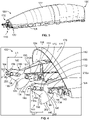
- FIG. 3 illustrates a perspective lateral view of the canopy 120, according to an example of the present disclosure.
- the canopy 120 includes the transparent cover 122 coupled to the frame 124.
- the canopy 120 includes a fore end 130 and an aft end 132 that is opposite from the fore end 130.
- a pivot assembly 140 connects to the frame 124.
- the pivot assembly 140 rearwardly extends from an aft end 133 of the frame 124.
- the pivot assembly 140 pivotally connects to portions of the fuselage 108 to allow the canopy 120 to open and close relative to the fuselage 108.
- the pivot assembly 140 pivotally couples to pivot pins of the fuselage 108.
- FIG. 4 illustrates a perspective lateral view of the pivot assembly 140 of the canopy 120, according to an example of the present disclosure.
- the pivot assembly 140 includes a first hinge 142 extending rearwardly from a first side 144 of the frame 124, and a second hinge 146 extending rearwardly from a second side 148 of the frame 124.
- the first hinge 142 is opposite from the second hinge 146. That is, the first hinge 142 is on a first side of the canopy 120, and the second hinge 146 is on an opposite second side of the canopy 120.
- the first hinge 142 can connect to the frame 124 through a first extension beam 150, and the second hinge 146 can connect to the frame 124 through a second extension beam 152.
- the first hinge 142 and the second hinge 146 can connect to the frame 124 without extension beams.
- the first hinge 142 includes a first fork 154 having an upper prong 156 separated from a lower prong 158 by a first pivot slot 160 having an open aft end 162 and a closed fore end 164.
- the first fork 154 connects to an intermediate body 166 having a first locking slot 168 having a closed aft end 170 and an open fore end 172.
- a hinge cam 174 having an outer arcuate surface 176 at a fore end 178 extends from (such as below) the intermediate body 166.
- the second hinge 146 includes a second fork 180 having an upper prong 182 separated from a lower prong 184 by a second pivot slot 186 having an open aft end 188 and a closed fore end 190.
- the second fork 180 connects to an intermediate body 192 having a second locking slot 194 having a closed aft end 196 and an open fore end 198.
- a hinge cam 200 having an outer arcuate surface 202 at a fore end 204 extends from (such as below) the intermediate body 192.
- the fuselage 108 includes aft pins 210 and fore pins 212.
- the aft pins 210 and the fore pins 212 are fixed structures of the fuselage 108 onto which the pivot assembly 140 secures.
- the pivot assembly 140 pivotally secures to the aft pins 210 and the fore pins 212.
- the first pivot slot 160 retains an aft pin 210
- the second pivot slot 186 retains an aft pin 210.
- the first locking slot 168 retains a first fore pin 212a (for example, a cam roller), and the second locking slot 194 retains a second fore pin 212b.
- the first fork 154 includes a first length L1.
- the upper prong 156 and the lower prong 158 have the length L1, thereby providing the first pivot slot 160 with the length L1.
- the second fork 180 includes a second length L2, which differs from L1.
- the second length L2 is less than the first length L1.
- the upper prong 182 and the lower prong 184 have the length L2, thereby providing the second pivot slot 186 with the length L2.
- the first length L1 may be less than the second length L2.
- the first length L1 exceeds the second length L2 by a distance that equals (or substantially equals, such as within +/- 0.1 inches or +/- 2.5 mm) a radius 220 of a pin, such as the aft pin 210.
- the second length L2 is shorter than the first length L1 by a distance that equals (or substantially equals) a radius 220 of a pin.
- the aft pins 210 and the fore pins 212 can have the same radius.
- the first length L1 can be 0.5 inches or approximately 0.5 inches (such as +/- 0.1 inches) longer than the second length L2 (or the second length L2 is 0.5 inches shorter than the first length L1).
- the first length L1 can be 1.3cm or approximately 1.3 cm (such as +/- 2.5 mm) longer than the second length L2 (or the second length L2 is 1.3 cm shorter than the first length L1).
- the difference between the first length L1 and the second length L2 can be greater or less than 0.5 inches or 1.3 cm.
- the difference between the first length L1 and the second length L2 can be between 0.1 inch to 1.5 inches or 2.5 mm to 3.8 cm. It has been found that the difference between the first length L1 and the second length L2 being 0.5 inches or 1.3 cm ensures a desired separation between the canopy 120 and the fuselage 108 that reduces the potential of collision with an ejecting occupant during an ejection event.
- Figure 5 illustrates a perspective interior view of the first hinge 142 of the pivot assembly 140, according to an example of the present disclosure.
- the second hinge 146 shown in Figure 4
- An aft end 230 of the lower prong 158 such as a distal tip, has a chamfer 232 (for example, a beveled surface) such as on a pin-engaging surface 234 and an interior surface 236.
- the chamfer 232 is an angled surface that provides a slope between the pin-engaging surface 234 and the interior surface 236.
- the upper prong 156 also includes a chamfer 232.
- each of the upper prong 156, the lower prong 158, the upper prong 182, and the lower prong 184 includes a chamfer 232. Accordingly, at least one of the upper prong 156, the lower prong 158, the upper prong 182, and the lower prong 184 includes a chamfer 232.
- the chamfer(s) 232 reduces the potential of binding between the first and second hinges 142 and 146 and respective aft pins 210 as the canopy 120 separates from the fuselage 108.
- the first hinge 142 and the second hinge 146 may not include any chamfers.
- the canopy 120 includes the pivot assembly 140 including the first hinge 142 and the second hinge 146 opposite from the first hinge 142.
- the first hinge 142 includes the first pivot slot 160 having the first length L1.
- the first pivot slot 160 is configured to retain a first aft pin 210a of the fuselage 108 of the aircraft 100.
- the second hinge 146 includes the second pivot slot 186 having the second length L2.
- the second pivot slot 186 is configured to retain a second aft pin 210b of the fuselage 108 of the aircraft 100.
- the first length L1 differs from the second length L2.
- the first length L1 is longer than the second length by a distance that is equal to or substantially equal to the radius 220, such as of one or both of the first aft pin 210a or the second aft pin 210b.
- the first length L1 exceeds the second length L2 by 0.5 inches or approximately 0.5 inches (or 1.3 cm or approximately 1.3 cm).
- one or both of the first hinge 142 or the second hinge 146 further includes one or more chamfers 232.
- the chamfer(s) 232 slope from a pin-engaging surface 234 to an interior surface 236.
- Figure 6 illustrates a perspective lateral view of the second hinge 146 of the pivot assembly 140 when the canopy 120 is in a closed and locked state, according to an example of the present disclosure.
- the first hinge 142 shown in Figure 4
- Figure 6 illustrates a perspective lateral view of the second hinge 146 of the pivot assembly 140 when the canopy 120 is in a closed and locked state, according to an example of the present disclosure.
- the first hinge 142 shown in Figure 4
- Figure 6 illustrates a perspective lateral view of the second hinge 146 of the pivot assembly 140 when the canopy 120 is in a closed and locked state, according to an example of the present disclosure.
- the first hinge 142 shown in Figure 4
- the canopy 120 is in the closed and locked state, such that the fore pin 212 is nested into the closed aft end 196 of the second locking slot 194 (a fore pin 212 is similarly nested into the closed aft end 170 of the first locking slot 168).
- the aft pin 210 is spaced away from the closed fore end 190 of the second pivot slot 186, and is positioned between distal tips of the upper prong 182 and the lower prong 184 (an aft pin 210 is similarly positioned in the first pivot slot 160). In this position, the aft pins 210 may rest on chamfers 232.
- Figure 7 illustrates a perspective lateral view of the second hinge 146 of the pivot assembly 140 during a first phase of an ejection event, according to an example of the present disclosure.
- the canopy 120 is driven rearwardly in the direction of arrow A, such that the fore pin 212 slides through the second locking slot 194 away from the closed fore end 190, while the aft pin 210 slides through the second pivot slot 186 toward the closed fore end 190.
- the fore pin 212 moves out of the second locking slot 194 and engages the arcuate outer surface 202 of the hinge cam 200.
- the canopy 120 is now unlocked and is free rotate about the aft pins 210.
- Figure 8 illustrates a perspective lateral view of the pivot assembly 140 during a second phase of an ejection event, according to an example of the present disclosure.
- Figure 9 illustrates a lateral view of the canopy 120 during the second phase of the ejection event.
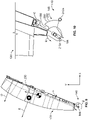
- Figure 10 illustrates a lateral view of the second hinge 146 during the second phase of the ejection event.
- the hinge cams 200 ride against the fore pins 212, thereby constraining motion of the canopy 120 to rotation about the aft pins 210.
- the fore pins 212 are free of the hinge cams 200, the canopy 120 is free to translate radially in the direction of arrows C along the first pivot slot 160 and the second pivot slot 186.
- Figure 11 illustrates a perspective front view of the canopy 120 during a third phase of the ejection event, according to an example of the present disclosure.
- Figure 12 illustrates a perspective view of the pivot assembly 140 during the third phase of the ejection event.
- the aft pin 210 remains in the first pivot slot 160 longer than the opposite aft pin 210 remains in the second pivot slot 186, thereby causing the canopy 120 to rotate out of the X-Y plane, such as to a side of the X-Y plane.
- the chamfer(s) 232 ensure that the first hinge 142 and the second hinge 146 do not bind or otherwise remain coupled to the aft pins 210.
- Net torque causes the canopy to rotate and roll about the aft pin 210 within the first pivot slot 160 in the direction of arc G.
- the chamfers 232 allow unimpeded rolling motion of the pivot assembly 140. As the canopy rolls rearwardly and to a side, forces due to rocket thrust and aerodynamic loads cause the canopy 120 to roll rearwardly and off to a side about the pivot point of the aft pin 210 within the first pivot slot 160.
- Figure 13 illustrates a lateral view of the aircraft 100 as the canopy 120 separates from the fuselage 108, according to an example of the present disclosure.
- Figure 14 illustrates a top view of the aircraft 100 as the canopy 120 separates from the fuselage 108.
- the difference in lengths L1 and L2 cause the canopy 120 to separate from the fuselage and move along a trajectory 300 that is below and laterally shifted from a trajectory 302 of an ejection seat.
- the pivot assembly 140 having the first hinge 142 with the length L1 and the second hinge with the length L2 reduces a potential of the jettisoned canopy colliding with the ejection seat. It is to be understood that the trajectories 300 and 302 shown in Figures 13 and 14 are not to scale.
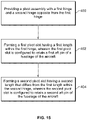
- Figure 15 illustrates a flow chart of a method of forming a canopy of an aircraft, according to an example of the present disclosure.
- the method includes providing, at 400, a pivot assembly with a first hinge and a second hinge opposite from the first hinge; forming, at 402, a first pivot slot having a first length within the first hinge, wherein the first pivot slot is configured to retain a first aft pin of a fuselage of the aircraft; and forming, at 404, a second pivot slot having a second length that differs from the first length within the second hinge, wherein the second pivot slot is configured to retain a second aft pin of the fuselage of the aircraft.
- the first length is longer than the second length by a distance that is equal to or substantially equal to a radius of one or both of the first aft pin or the second aft pin.
- the first length exceeds the second length by 0.5 inches or approximately 0.5 inches (or 1.3 cm or approximately 1.3 cm).
- the method further includes forming one or more chamfers on one or both of the first hinge or the second hinge.
- the forming the one or more chamfers includes sloping the one or more chamfers from a pin-engaging surface to an interior surface.
- examples of the present disclosure provide systems and methods for safely, efficiently, and effectively separating a canopy from a fuselage of an aircraft during an ejection procedure. Further, examples of the present disclosure provide systems and methods that are less costly and less complex than prior systems and methods for canopy separation. Additionally, examples of the present disclosure provide systems and methods that do not add weight to the aircraft.
- a structure, limitation, or element that is "configured to” perform a task or operation is particularly structurally formed, constructed, or adapted in a manner corresponding to the task or operation.
- an object that is merely capable of being modified to perform the task or operation is not “configured to” perform the task or operation as used herein.
Landscapes
- Engineering & Computer Science (AREA)
- Aviation & Aerospace Engineering (AREA)
- Mechanical Engineering (AREA)
- Business, Economics & Management (AREA)
- Emergency Management (AREA)
- Pivots And Pivotal Connections (AREA)
- Tires In General (AREA)
Abstract
Description
- Examples of the present disclosure generally relate to systems and methods for separating a canopy from a fuselage of an aircraft.
- Certain aircraft include a canopy over a cockpit. For example, various military fighter jets include a canopy over a cockpit. The canopy is moveable between an open position, which allows a pilot to enter and exit the cockpit, and a closed position, such as during flight of the aircraft.
- During a mission, a pilot may need to eject from the cockpit. For example, the aircraft may be impacted by adversarial ordnance, which may render the aircraft inoperable. As the pilot pulls an ejection seat firing handle to initiate an escape system, a transparency of the canopy is weakened or removed before the seat assembly, on which the pilot is seated, is ejected from the cockpit.
- During ejection, the canopy is jettisoned prior to ejecting the occupant(s) of the cockpit to ensure a clear escape path. For an aircraft moving in a forward direction, as the canopy is jettisoned, the canopy continues to travel down range, such that the trajectory of the jettisoned canopy is dictated by gravity and aerodynamic forces. After the canopy is jettisoned, the occupant(s) are ejected from the aircraft via ejection seat(s).
- In order to stop an impact between the jettisoned canopy and the aircrew from occurring, a known method utilizes trajectory divergent rocket motors on the ejection seat(s) to induce lateral motion of the ejection seat(s). Another known method induces a center of gravity offset into the canopy via a ballast. However, the additional rocket motors and/or ballasts add weight, complexity, and cost to the aircraft.
- A need exists for a system and a method for safely, efficiently, and effectively separating a canopy from a fuselage of an aircraft during an ejection procedure. Further, a need exists for such a system and a method that is less costly and less complex than known systems and methods. Additionally, a need exists for such a system and a method that does not add weight to the aircraft.
- With those needs in mind, certain examples of the present disclosure provide a canopy for an aircraft. The canopy includes a pivot assembly including a first hinge and a second hinge opposite from the first hinge. The first hinge includes a first pivot slot having a first length. The first pivot slot is configured to retain a first aft pin of a fuselage of the aircraft. The second hinge includes a second pivot slot having a second length. The second pivot slot is configured to retain a second aft pin of the fuselage of the aircraft. The first length differs from the second length.
- In at least one example, the first length is longer than the second length by a distance that is equal to or substantially equal to a radius of one or both of the first aft pin or the second aft pin. As an example, the first length exceeds the second length by 0.5 inches or approximately 0.5 inches (or 1.3 cm or approximately 1.3 cm).
- In at least one example, one or both of the first hinge or the second hinge further includes one or more chamfers. As an example, the one or more chamfers slope from a pin-engaging surface to an interior surface.
- In at least one example, the first hinge further includes a first fork having a first upper prong separated from a first lower prong by the first pivot slot. The second hinge further includes a second fork having a second upper prong separated from a second lower prong by the second pivot slot.
- As a further example, the first hinge further includes a first intermediate body having a first locking slot configured to retain a first fore pin of the fuselage of the aircraft. The second hinge further includes a second intermediate body having a second locking slot configured to retain a second fore pin of the fuselage of the aircraft.
- As a further example, the first hinge further includes a first hinge cam extending from the first intermediate body. The second hinge further includes a second hinge cam extending from the second intermediate body.
- In at least one example, the canopy further includes a transparent cover secured to a frame. The pivot assembly extends from the frame. For example, the pivot assembly rearwardly extends from an aft end of the frame.
- Certain examples of the present disclosure provide a method of forming a canopy for an aircraft. The method includes providing a pivot assembly with a first hinge and a second hinge opposite from the first hinge; forming a first pivot slot having a first length within the first hinge, wherein the first pivot slot is configured to retain a first aft pin of a fuselage of the aircraft; and forming a second pivot slot having a second length that differs from the first length within the second hinge, wherein the second pivot slot is configured to retain a second aft pin of the fuselage of the aircraft.
- Certain examples of the present disclosure provide an aircraft including a fuselage including a first aft pin, a second aft pin, a first fore pin, and a second fore pin; and a canopy moveably coupled to the fuselage, as described herein. The canopy is configured to be move between an open position and closed position.
-
-
Figure 1 illustrates a perspective front view of an aircraft. -
Figure 2 illustrates a lateral view of the aircraft ofFigure 1 . -
Figure 3 illustrates a perspective lateral view of a canopy. -
Figure 4 illustrates a perspective lateral view of a pivot assembly of the canopy -
Figure 5 illustrates a perspective interior view of a first hinge of the pivot assembly. -
Figure 6 illustrates a perspective lateral view of a second hinge of the pivot assembly when the canopy is in a closed and locked state. -
Figure 7 illustrates a perspective lateral view of the second hinge of the pivot assembly during a first phase of an ejection event. -
Figure 8 illustrates a perspective lateral view of the pivot assembly during a second phase of an ejection event. -
Figure 9 illustrates a lateral view of the canopy during the second phase of the ejection event. -
Figure 10 illustrates a lateral view of the second hinge during the second phase of the ejection event. -
Figure 11 illustrates a perspective front view of the canopy during a third phase of the ejection event. -
Figure 12 illustrates a perspective view of the pivot assembly during the third phase of the ejection event. -
Figure 13 illustrates a lateral view of the aircraft as the canopy separates from the fuselage. -
Figure 14 illustrates a top view of the aircraft as the canopy separates from the fuselage. -
Figure 15 illustrates a flow chart of a method of forming a canopy of an aircraft. - The foregoing summary, as well as the following detailed description of certain examples will be better understood when read in conjunction with the appended drawings. As used herein, an element or step recited in the singular and preceded by the word "a" or "an" should be understood as not necessarily excluding the plural of the elements or steps. Further, references to "one example" are not intended to be interpreted as excluding the existence of additional examples that also incorporate the recited features. Moreover, unless explicitly stated to the contrary, examples "comprising" or "having" an element or a plurality of elements having a particular condition can include additional elements not having that condition.
- Certain examples of the present disclosure provide a separating system and method for a canopy of an aircraft. The system and method are configured to mechanically induce a controlled rolling motion into the canopy via a canopy hinge design. The system and method include a pivot assembly having a first hinge opposite from a second hinge. A slot length differential exists between the first hinge and the second hinge. The slot length differential allows the effects of centrifugal acceleration, aerodynamic forces, and canopy jettison rocket motor thrust to impart a predictable and controlled rotational velocity about a longitudinal axis of the canopy. When the canopy rotates along the longitudinal axis, aerodynamic forces and canopy jettison rocket motor thrust impart lateral impulse and velocity into the canopy, causing the trajectory of the canopy to deviate from a trajectory of the ejected occupant(s) of the aircraft. The system and method prevent or otherwise reduce a potential of collision between a jettisoned aircraft canopy and the ejected occupant(s) during an emergency escape event.
- The systems and methods described herein utilize centrifugal acceleration, radial translation, and external forces (such as caused by, for example, aerodynamic and jettison rocket motors) to impart rotational and lateral impulses into the canopy resulting in a trajectory that diverges from that of the ejection seat/occupant. The system and method introduce different slot lengths on opposed hinge mechanisms, for example. Examples of the present disclosure provide systems and methods that are repeatable and reliable, robust, and insensitive to mass property variables and/or future modification to the canopy system. Further, examples of the present disclosure allow for mathematical quantification and prediction of performance as well as optimization of pivot slot geometry. The ability to predict performance has the tendency to increase the probability of successfully demonstrating adequate canopy/aircrew trajectory separation during ejection sled testing. In contrast, previous aircraft platforms typically required multiple sled tests prior to realize an effective means for canopy lateral motion. Further, the systems and methods provide canopy separation systems and methods that are less costly than known systems and methods.
- As described herein, the slot length differential (difference in length of pivot slots) of the canopy produces a rolling motion of the canopy via the hinge as the canopy separates from the fuselage of the aircraft.
-
Figure 1 illustrates a perspective front view of anaircraft 100, according to an example of the present disclosure. As shown, theaircraft 100 is a military fighter jet. Theaircraft 100 includes apropulsion system 102 that includes twoengines 104, for example. Optionally, thepropulsion system 102 may include more orless engines 104 than shown. Theengines 104 are carried bywings 106 and/or afuselage 108 of theaircraft 100. In other examples, theengines 104 may be carried by other portions of theaircraft 100. Thefuselage 108 also supportshorizontal stabilizers 110 andvertical stabilizers 112. Thefuselage 108 of theaircraft 100 includes thecockpit 114 covered by acanopy 120. Optionally, theaircraft 100 may be various other types of military aircraft. Alternatively, the aircraft may be various types of commercial aircraft. - The
canopy 120 includes atransparent cover 122 secured to aframe 124. Thetransparent cover 122 is formed of a robust, sturdy, and transparent material, such as acrylic. Theframe 124 may be formed of metal. Thecanopy 120 is moveable between an open position, in which a pilot may enter and exit the cockpit, and a closed position, such as during flight of theaircraft 100. - The
cockpit 114 includes a seat assembly (not shown). In at least one example, the assembly includes pyrotechnic components, such as rockets, integrated therein, to allow for ejection of the seat assembly. An eject mechanism (not shown) is disposed within thecockpit 114. The eject mechanism may be secured to a portion of the seat assembly. The eject mechanism may be an eject handle or button, for example. -
Figure 2 illustrates a lateral view of theaircraft 100 ofFigure 1 . During an emergency ejection process, thecanopy 120 is jettisoned to ensure a safe, unimpeded path for the ejection of the seat(s) that support the occupant(s). As an example, during the ejection process, an occupant (such as a pilot) pulls an ejection seat handle within thecockpit 114. In response, thecanopy 120 linearly translates to unlock, such as via pyrotechnic thrusters. Thecanopy 120 rotates about aircraft pivot pins, such as via canopy jettison rocket motors or other pyrotechnic devices to rotate rearwardly topositions 120' and 120", for example. A signal indicating an ejection sequence is sent. The signal indicates that thecanopy 120 has rotated to a predetermined angle to trigger a seat firing sequence. The seat(s) and occupant(s) are then ejected. -
Figure 3 illustrates a perspective lateral view of thecanopy 120, according to an example of the present disclosure. Thecanopy 120 includes thetransparent cover 122 coupled to theframe 124. Thecanopy 120 includes afore end 130 and anaft end 132 that is opposite from thefore end 130. - A
pivot assembly 140 connects to theframe 124. For example, thepivot assembly 140 rearwardly extends from anaft end 133 of theframe 124. Referring toFigures 1-3 , thepivot assembly 140 pivotally connects to portions of thefuselage 108 to allow thecanopy 120 to open and close relative to thefuselage 108. In at least one example, thepivot assembly 140 pivotally couples to pivot pins of thefuselage 108. -
Figure 4 illustrates a perspective lateral view of thepivot assembly 140 of thecanopy 120, according to an example of the present disclosure. Thepivot assembly 140 includes afirst hinge 142 extending rearwardly from afirst side 144 of theframe 124, and asecond hinge 146 extending rearwardly from asecond side 148 of theframe 124. Thefirst hinge 142 is opposite from thesecond hinge 146. That is, thefirst hinge 142 is on a first side of thecanopy 120, and thesecond hinge 146 is on an opposite second side of thecanopy 120. Thefirst hinge 142 can connect to theframe 124 through afirst extension beam 150, and thesecond hinge 146 can connect to theframe 124 through asecond extension beam 152. Optionally, thefirst hinge 142 and thesecond hinge 146 can connect to theframe 124 without extension beams. - The
first hinge 142 includes afirst fork 154 having anupper prong 156 separated from alower prong 158 by afirst pivot slot 160 having an openaft end 162 and a closedfore end 164. Thefirst fork 154 connects to anintermediate body 166 having afirst locking slot 168 having a closedaft end 170 and an openfore end 172. Ahinge cam 174 having an outerarcuate surface 176 at afore end 178 extends from (such as below) theintermediate body 166. - Similarly, the
second hinge 146 includes asecond fork 180 having anupper prong 182 separated from alower prong 184 by asecond pivot slot 186 having an openaft end 188 and a closedfore end 190. Thesecond fork 180 connects to anintermediate body 192 having asecond locking slot 194 having a closedaft end 196 and an openfore end 198. Ahinge cam 200 having an outerarcuate surface 202 at afore end 204 extends from (such as below) theintermediate body 192. - Referring to
Figures 1-4 , thefuselage 108 includes aft pins 210 and fore pins 212. The aft pins 210 and the fore pins 212 are fixed structures of thefuselage 108 onto which thepivot assembly 140 secures. Thepivot assembly 140 pivotally secures to the aft pins 210 and the fore pins 212. For example, thefirst pivot slot 160 retains an aft pin 210, and thesecond pivot slot 186 retains an aft pin 210. Thefirst locking slot 168 retains afirst fore pin 212a (for example, a cam roller), and thesecond locking slot 194 retains a secondfore pin 212b. - The
first fork 154 includes a first length L1. Theupper prong 156 and thelower prong 158 have the length L1, thereby providing thefirst pivot slot 160 with the length L1. Thesecond fork 180 includes a second length L2, which differs from L1. In particular, the second length L2 is less than the first length L1. Theupper prong 182 and thelower prong 184 have the length L2, thereby providing thesecond pivot slot 186 with the length L2. Optionally, the first length L1 may be less than the second length L2. - In at least one example, the first length L1 exceeds the second length L2 by a distance that equals (or substantially equals, such as within +/- 0.1 inches or +/- 2.5 mm) a
radius 220 of a pin, such as the aft pin 210. Put differently, the second length L2 is shorter than the first length L1 by a distance that equals (or substantially equals) aradius 220 of a pin. The aft pins 210 and the fore pins 212 can have the same radius. As an example, the first length L1 can be 0.5 inches or approximately 0.5 inches (such as +/- 0.1 inches) longer than the second length L2 (or the second length L2 is 0.5 inches shorter than the first length L1). As another example, the first length L1 can be 1.3cm or approximately 1.3 cm (such as +/- 2.5 mm) longer than the second length L2 (or the second length L2 is 1.3 cm shorter than the first length L1). Optionally, the difference between the first length L1 and the second length L2 can be greater or less than 0.5 inches or 1.3 cm. For example, the difference between the first length L1 and the second length L2 can be between 0.1 inch to 1.5 inches or 2.5 mm to 3.8 cm. It has been found that the difference between the first length L1 and the second length L2 being 0.5 inches or 1.3 cm ensures a desired separation between thecanopy 120 and thefuselage 108 that reduces the potential of collision with an ejecting occupant during an ejection event. -
Figure 5 illustrates a perspective interior view of thefirst hinge 142 of thepivot assembly 140, according to an example of the present disclosure. For clarity, the second hinge 146 (shown inFigure 4 ) is not shown inFigure 5 . Anaft end 230 of thelower prong 158, such as a distal tip, has a chamfer 232 (for example, a beveled surface) such as on a pin-engagingsurface 234 and aninterior surface 236. For example, thechamfer 232 is an angled surface that provides a slope between the pin-engagingsurface 234 and theinterior surface 236. In at least one example, theupper prong 156 also includes achamfer 232. Referring toFigures 4 and5 , each of theupper prong 156, thelower prong 158, theupper prong 182, and thelower prong 184 includes achamfer 232. Accordingly, at least one of theupper prong 156, thelower prong 158, theupper prong 182, and thelower prong 184 includes achamfer 232. The chamfer(s) 232 reduces the potential of binding between the first andsecond hinges canopy 120 separates from thefuselage 108. Alternatively, thefirst hinge 142 and thesecond hinge 146 may not include any chamfers. - Referring to
Figures 1-6 , examples of the present disclosure provide thecanopy 120 for theaircraft 100. Thecanopy 120 includes thepivot assembly 140 including thefirst hinge 142 and thesecond hinge 146 opposite from thefirst hinge 142. Thefirst hinge 142 includes thefirst pivot slot 160 having the first length L1. Thefirst pivot slot 160 is configured to retain a firstaft pin 210a of thefuselage 108 of theaircraft 100. Thesecond hinge 146 includes thesecond pivot slot 186 having the second length L2. Thesecond pivot slot 186 is configured to retain a secondaft pin 210b of thefuselage 108 of theaircraft 100. The first length L1 differs from the second length L2. For example, the first length L1 is longer than the second length by a distance that is equal to or substantially equal to theradius 220, such as of one or both of the firstaft pin 210a or the secondaft pin 210b. As a further example, the first length L1 exceeds the second length L2 by 0.5 inches or approximately 0.5 inches (or 1.3 cm or approximately 1.3 cm). - In at least one example, one or both of the
first hinge 142 or thesecond hinge 146 further includes one ormore chamfers 232. As an example, the chamfer(s) 232 slope from a pin-engagingsurface 234 to aninterior surface 236. -
Figure 6 illustrates a perspective lateral view of thesecond hinge 146 of thepivot assembly 140 when thecanopy 120 is in a closed and locked state, according to an example of the present disclosure. For the sake of clarity, the first hinge 142 (shown inFigure 4 ) is not shown inFigure 6 . Referring toFigures 1-6 , during flight, for example, thecanopy 120 is in the closed and locked state, such that the fore pin 212 is nested into the closedaft end 196 of the second locking slot 194 (a fore pin 212 is similarly nested into the closedaft end 170 of the first locking slot 168). Meanwhile, the aft pin 210 is spaced away from the closedfore end 190 of thesecond pivot slot 186, and is positioned between distal tips of theupper prong 182 and the lower prong 184 (an aft pin 210 is similarly positioned in the first pivot slot 160). In this position, the aft pins 210 may rest onchamfers 232. -
Figure 7 illustrates a perspective lateral view of thesecond hinge 146 of thepivot assembly 140 during a first phase of an ejection event, according to an example of the present disclosure. As an emergency ejection is initiated, thecanopy 120 is driven rearwardly in the direction of arrow A, such that the fore pin 212 slides through thesecond locking slot 194 away from the closedfore end 190, while the aft pin 210 slides through thesecond pivot slot 186 toward the closedfore end 190. The fore pin 212 moves out of thesecond locking slot 194 and engages the arcuateouter surface 202 of thehinge cam 200. Thecanopy 120 is now unlocked and is free rotate about the aft pins 210. -
Figure 8 illustrates a perspective lateral view of thepivot assembly 140 during a second phase of an ejection event, according to an example of the present disclosure.Figure 9 illustrates a lateral view of thecanopy 120 during the second phase of the ejection event.Figure 10 illustrates a lateral view of thesecond hinge 146 during the second phase of the ejection event. Referring toFigures 8-10 , while thecanopy 120 rotates about the aft pins 210 in the direction of arcs B, thehinge cams 200 ride against the fore pins 212, thereby constraining motion of thecanopy 120 to rotation about the aft pins 210. Once the fore pins 212 are free of thehinge cams 200, thecanopy 120 is free to translate radially in the direction of arrows C along thefirst pivot slot 160 and thesecond pivot slot 186. - When the
hinge cams Figure 4 ) and thesecond locking slot 194 is no longer constrained.Centrifugal acceleration 250 causes thecanopy 120 to translate radially along thefirst pivot slot 160 and thesecond pivot slot 186. Thecanopy 120 continues to rotate about the respective aft pins 210 within thefirst pivot slot 160 and thesecond pivot slot 186. Because both the respective aft pins 210 are still within thefirst pivot slot 160 and thesecond pivot slot 186, rotation of thecanopy 120 in the direction of arc B occurs in an X-Y plane. Additional force in the direction of arrow D may be exerted by rocket thrust. Further, aerodynamic force is exerted in the direction of arrow E. Acceleration caused by gravity is exerted in the direction of arrow F. -
Figure 11 illustrates a perspective front view of thecanopy 120 during a third phase of the ejection event, according to an example of the present disclosure.Figure 12 illustrates a perspective view of thepivot assembly 140 during the third phase of the ejection event. Referring toFigures 4 ,11 , and12 , because thefirst pivot slot 160 is longer than thesecond pivot slot 186, the aft pin 210 remains in thefirst pivot slot 160 longer than the opposite aft pin 210 remains in thesecond pivot slot 186, thereby causing thecanopy 120 to rotate out of the X-Y plane, such as to a side of the X-Y plane. That is, when both the aft pins 210 are engaged within the first andsecond pivot slots second hinge 146 disengages from the aft pin 210 (because of the shorter length L2), thecanopy 120 rotates about a single point, namely the aft pin 210 within thefirst pivot slot 160. As such, the plane of rotation is no longer constrained in relation to the X-Y plane, and thecanopy 120 rotates rearwardly and off to a side. - Referring to
Figures 4 ,5 ,11 , and12 , the chamfer(s) 232 ensure that thefirst hinge 142 and thesecond hinge 146 do not bind or otherwise remain coupled to the aft pins 210. Net torque causes the canopy to rotate and roll about the aft pin 210 within thefirst pivot slot 160 in the direction of arc G. Thechamfers 232 allow unimpeded rolling motion of thepivot assembly 140. As the canopy rolls rearwardly and to a side, forces due to rocket thrust and aerodynamic loads cause thecanopy 120 to roll rearwardly and off to a side about the pivot point of the aft pin 210 within thefirst pivot slot 160. -
Figure 13 illustrates a lateral view of theaircraft 100 as thecanopy 120 separates from thefuselage 108, according to an example of the present disclosure.Figure 14 illustrates a top view of theaircraft 100 as thecanopy 120 separates from thefuselage 108. Referring toFigures 1-14 , the difference in lengths L1 and L2 cause thecanopy 120 to separate from the fuselage and move along atrajectory 300 that is below and laterally shifted from atrajectory 302 of an ejection seat. As such, thepivot assembly 140 having thefirst hinge 142 with the length L1 and the second hinge with the length L2 reduces a potential of the jettisoned canopy colliding with the ejection seat. It is to be understood that thetrajectories Figures 13 and 14 are not to scale. -
Figure 15 illustrates a flow chart of a method of forming a canopy of an aircraft, according to an example of the present disclosure. The method includes providing, at 400, a pivot assembly with a first hinge and a second hinge opposite from the first hinge; forming, at 402, a first pivot slot having a first length within the first hinge, wherein the first pivot slot is configured to retain a first aft pin of a fuselage of the aircraft; and forming, at 404, a second pivot slot having a second length that differs from the first length within the second hinge, wherein the second pivot slot is configured to retain a second aft pin of the fuselage of the aircraft. - In at least one example, the first length is longer than the second length by a distance that is equal to or substantially equal to a radius of one or both of the first aft pin or the second aft pin. As an example, the first length exceeds the second length by 0.5 inches or approximately 0.5 inches (or 1.3 cm or approximately 1.3 cm).
- In at least one example, the method further includes forming one or more chamfers on one or both of the first hinge or the second hinge. For example, the forming the one or more chamfers includes sloping the one or more chamfers from a pin-engaging surface to an interior surface.
- Further, the disclosure comprises examples according to the following clauses:
- Clause 1. A canopy for an aircraft, the canopy comprising: a pivot assembly comprising a first hinge and a second hinge opposite from the first hinge, wherein the first hinge comprises a first pivot slot having a first length, wherein the first pivot slot is configured to retain a first aft pin of a fuselage of the aircraft, wherein the second hinge comprises a second pivot slot having a second length, wherein the second pivot slot is configured to retain a second aft pin of the fuselage of the aircraft, and wherein the first length differs from the second length.
- Clause 2. The canopy of Clause 1, wherein the first length is longer than the second length by a distance that is equal to or substantially equal to a radius of one or both of the first aft pin or the second aft pin.
- Clause 3. The canopy of Clauses 1 or 2, wherein the first length exceeds the second length by approximately 0.5 inches or approximately 1.3 cm.
-
Clause 4. The canopy of any of Clauses 1-3, wherein one or both of the first hinge or the second hinge further comprises one or more chamfers. - Clause 5. The canopy of
Clause 4, wherein the one or more chamfers slope from a pin-engaging surface to an interior surface. - Clause 6. The canopy of any of Clauses 1-5, wherein the first hinge further comprises a first fork having a first upper prong separated from a first lower prong by the first pivot slot, and wherein the second hinge further comprises a second fork having a second upper prong separated from a second lower prong by the second pivot slot.
-
Clause 7. The canopy of Clause 6, wherein the first hinge further comprises a first intermediate body having a first locking slot configured to retain a first fore pin of the fuselage of the aircraft, and wherein the second hinge further comprises a second intermediate body having a second locking slot configured to retain a second fore pin of the fuselage of the aircraft. - Clause 8. The canopy of
Clause 7, wherein the first hinge further comprises a first hinge cam extending from the first intermediate body, and wherein the second hinge further comprises a second hinge cam extending from the second intermediate body. - Clause 9. The canopy of any of Clauses 1-8, further comprising a transparent cover secured to a frame, wherein the pivot assembly extends from the frame.
- Clause 10. The canopy of Clause 9, wherein the pivot assembly rearwardly extends from an aft end of the frame.
- Clause 11. A method of forming a canopy for an aircraft, the method comprising: providing a pivot assembly with a first hinge and a second hinge opposite from the first hinge; forming a first pivot slot having a first length within the first hinge, wherein the first pivot slot is configured to retain a first aft pin of a fuselage of the aircraft; and forming a second pivot slot having a second length that differs from the first length within the second hinge, wherein the second pivot slot is configured to retain a second aft pin of the fuselage of the aircraft.
- Clause 12. The method of Clause 11, wherein the first length is longer than the second length by a distance that is equal to or substantially equal to a radius of one or both of the first aft pin or the second aft pin.
- Clause 13. The method of Clauses 11 or 12, wherein the first length exceeds the second length by approximately 0.5 inches or approximately 1.3 cm.
- Clause 14. The method of any of Clauses 11-13, further comprising forming one or more chamfers on one or both of the first hinge or the second hinge.
- Clause 15. The method of Clause 14, wherein said forming the one or more chamfers comprises sloping the one or more chamfers from a pin-engaging surface to an interior surface.
- Clause 16. An aircraft comprising: a fuselage including a first aft pin, a second aft pin, a first fore pin, and a second fore pin; and a canopy moveably coupled to the fuselage, wherein the canopy is configured to be move between an open position and closed position, the canopy comprising: a transparent cover secured to a frame; and a pivot assembly extending from the frame, wherein the pivot assembly includes a first hinge and a second hinge opposite from the first hinge, wherein the first hinge comprises a first fork having a first upper prong separated from a first lower prong by a first pivot slot having a first length, wherein the first pivot slot retains the first aft pin, a first intermediate body having a first locking slot that retains the first fore pin, a first hinge cam extending from the first intermediate body, wherein the second hinge comprises a second fork having a second upper prong separated from a second lower prong by a second pivot slot having a second length, wherein the second pivot slot retains the second aft pin, a second intermediate body having a second locking slot that retains the second fore pin, and a second hinge cam extending from the second intermediate body, and wherein the first length differs from the second length.
- Clause 17. The aircraft of Clause 16, wherein the first length is longer than the second length by a distance that is equal to or substantially equal to a radius of one or both of the first aft pin or the second aft pin.
- Clause 18. The aircraft of Clauses 16 or 17, wherein the first length exceeds the second length by approximately 0.5 inches or approximately 1.3 cm.
- Clause 19. The aircraft of any of Clauses 16-18, wherein one or both of the first hinge or the second hinge further comprises one or more chamfers.
- Clause 20. The aircraft of Clause 19, wherein the one or more chamfers slope from a pin-engaging surface to an interior surface.
- As described herein, examples of the present disclosure provide systems and methods for safely, efficiently, and effectively separating a canopy from a fuselage of an aircraft during an ejection procedure. Further, examples of the present disclosure provide systems and methods that are less costly and less complex than prior systems and methods for canopy separation. Additionally, examples of the present disclosure provide systems and methods that do not add weight to the aircraft.
- While various spatial and directional terms, such as top, bottom, lower, mid, lateral, horizontal, vertical, front and the like can be used to describe examples of the present disclosure, it is understood that such terms are merely used with respect to the orientations shown in the drawings. The orientations can be inverted, rotated, or otherwise changed, such that an upper portion is a lower portion, and vice versa, horizontal becomes vertical, and the like.
- As used herein, a structure, limitation, or element that is "configured to" perform a task or operation is particularly structurally formed, constructed, or adapted in a manner corresponding to the task or operation. For purposes of clarity and the avoidance of doubt, an object that is merely capable of being modified to perform the task or operation is not "configured to" perform the task or operation as used herein.
- It is to be understood that the above description is intended to be illustrative, and not restrictive. For example, the above-described examples (and/or features thereof) can be used in combination with each other. In addition, many modifications can be made to adapt a particular situation or material to the teachings of the various examples of the disclosure. While the dimensions and types of materials described herein are intended to define the parameters of the various examples of the disclosure, the examples are by no means limiting. Many other examples will be apparent to those of skill in the art upon reviewing the above description. The scope of the various examples of the disclosure should, therefore, be determined with reference to the appended claims. In the appended claims and the detailed description herein, the terms "including" and "in which" are used as the plain-English equivalents of the respective terms "comprising" and "wherein." Moreover, the terms "first," "second," and "third," etc. are used merely as labels, and are not intended to impose numerical requirements on their objects.
- This written description discloses various examples to enable any person skilled in the art to practice various examples of the disclosure, including making and using any devices or systems and performing any incorporated methods. The patentable scope is defined by the claims, and can include other examples that occur to those skilled in the art.
Claims (15)
- A canopy (120) for an aircraft (100), the canopy (120) comprising:
a pivot assembly (140) comprising a first hinge (142) and a second hinge (146) opposite from the first hinge (142); and wherein:the first hinge (142) comprises a first pivot slot (160) having a first length (L1);the second hinge (146) comprises a second pivot slot (186) having a second length (L2); andthe first length (L1) differs from the second length (L2). - The canopy (120) of claim 1, wherein the first length (L1) exceeds the second length (L2) by approximately 0.5 inches (approximately 1.3 cm).
- The canopy (120) of claim 1 or 2, wherein:one or both of the first hinge (142) or the second hinge (146) further comprises one or more chamfers (232); and, optionally,the one or more chamfers (232) slope from a pin-engaging surface (234) to an interior surface (236).
- The canopy (120) of any of claims 1 to 3, wherein:the first hinge (142) further comprises a first fork (154) having a first upper prong (156) separated from a first lower prong (158) by the first pivot slot (160); andthe second hinge (146) further comprises a second fork (180) having a second upper prong (182) separated from a second lower prong (184) by the second pivot slot (186).
- The canopy (120) of any of claims 1 to 4, further comprising a transparent cover (122) secured to a frame (124), wherein the pivot assembly (140) extends from the frame (124).
- The canopy of claim 5, wherein the pivot assembly (140) rearwardly extends from an aft end (133) of the frame (124).
- An aircraft (100) comprising:a fuselage (108) including a first aft pin (210a) and a second aft pin (210b); andthe canopy (120) of any of claims 1 to 6; and wherein:the first pivot slot (160) is configured to retain the first aft pin (210a); andthe second pivot slot (186) is configured to retain the second aft pin (210b).
- The aircraft (100) of claim 7, wherein the first length (L1) is longer than the second length (L2) by a distance that is equal to or substantially equal to a radius (220) of the first aft pin (210a) and/or the second aft pin (210b).
- The aircraft (100) of claim 7 or 8, wherein:the fuselage (108) further comprises a first fore pin (212a) and a second fore pin (212b);the first hinge (142) further comprises a first intermediate body (166) having a first locking slot (168) configured to retain the first fore pin (212a); andthe second hinge (146) further comprises a second intermediate body (192) having a second locking slot (194) configured to retain the second fore pin (212b).
- The aircraft (100) of claim 9, wherein:the first hinge (142) further comprises a first hinge cam (174) extending from the first intermediate body (166); andthe second hinge (146) further comprises a second hinge cam (200) extending from the second intermediate body (192).
- A method of forming a canopy (120) for an aircraft (100), the method comprising:providing a pivot assembly (140) with a first hinge (142) and a second hinge (146) opposite from the first hinge (142);forming a first pivot slot (160) having a first length (L1) within the first hinge (142), wherein the first pivot slot (160) is configured to retain a first aft pin (210a) of a fuselage (108) of the aircraft (100); andforming a second pivot slot (186) having a second length (L2) that differs from the first length (L1) within the second hinge (146), wherein the second pivot slot (186) is configured to retain a second aft pin (210b) of the fuselage (108) of the aircraft (100).
- The method of claim 11, wherein the first length (L1) is longer than the second length (L2) by a distance that is substantially equal to a radius (220) of one or both of the first aft pin (210a) or the second aft pin (210b).
- The method of claim 11 or 12, wherein the first length (L1) exceeds the second length (L2) by approximately 0.5 inches (approximately 1.3 cm).
- The method of any of claims 11 to 13, further comprising forming one or more chamfers (232) on one or both of the first hinge (142) or the second hinge (146).
- The method of claim 14, wherein said forming the one or more chamfers (232) comprises sloping the one or more chamfers (232) from a pin-engaging surface (234) to an interior surface (236).
Applications Claiming Priority (2)
| Application Number | Priority Date | Filing Date | Title |
|---|---|---|---|
| US202163146048P | 2021-02-05 | 2021-02-05 | |
| US17/468,973 US11623730B2 (en) | 2021-02-05 | 2021-09-08 | Canopy separation systems and methods for an aircraft |
Publications (2)
| Publication Number | Publication Date |
|---|---|
| EP4039582A1 true EP4039582A1 (en) | 2022-08-10 |
| EP4039582B1 EP4039582B1 (en) | 2024-07-24 |
Family
ID=78516644
Family Applications (1)
| Application Number | Title | Priority Date | Filing Date |
|---|---|---|---|
| EP21206245.9A Active EP4039582B1 (en) | 2021-02-05 | 2021-11-03 | Canopy separation systems and methods for an aircraft |
Country Status (4)
| Country | Link |
|---|---|
| US (1) | US11623730B2 (en) |
| EP (1) | EP4039582B1 (en) |
| JP (1) | JP2022120777A (en) |
| CN (1) | CN114852346A (en) |
Families Citing this family (3)
| Publication number | Priority date | Publication date | Assignee | Title |
|---|---|---|---|---|
| TR202022489A2 (en) * | 2020-12-30 | 2022-07-21 | Tusas Tuerk Havacilik Ve Uzay Sanayii Anonim Sirketi | An aircraft. |
| KR102931960B1 (en) | 2023-10-13 | 2026-03-04 | 한국항공우주산업 주식회사 | Rotary canopy actuator with elliptic curved links |
| TR2023019488A2 (en) | 2023-12-29 | 2025-07-21 | Tusas Tuerk Havacilik Ve Uzay Sanayii Anonim Sirketi | A canopy movement system. |
Citations (4)
| Publication number | Priority date | Publication date | Assignee | Title |
|---|---|---|---|---|
| US2699305A (en) * | 1951-06-14 | 1955-01-11 | Howard L Turner | Aircraft canopy escape capsule |
| US2832553A (en) * | 1955-01-12 | 1958-04-29 | North American Aviation Inc | Canopy actuating and ejecting assembly |
| US3194517A (en) * | 1963-12-20 | 1965-07-13 | Northrop Corp | Cockpit enclosure and operating mechanism |
| EP0437982A1 (en) * | 1990-01-16 | 1991-07-24 | British Aerospace Public Limited Company | Canopy or cover assemblies and pivot arrangements |
Family Cites Families (2)
| Publication number | Priority date | Publication date | Assignee | Title |
|---|---|---|---|---|
| ITTO20080099A1 (en) * | 2008-02-08 | 2009-08-09 | Alenia Aeronautica Spa | DOOR STRUCTURE FOR A COMPARTMENT IN THE FUSELERA OR IN THE WING OF A AIRCRAFT |
| US20200255116A1 (en) * | 2019-02-07 | 2020-08-13 | Harper Engineering Co. | Aircraft hinge apparatus and related methods for the same |
-
2021
- 2021-09-08 US US17/468,973 patent/US11623730B2/en active Active
- 2021-11-03 EP EP21206245.9A patent/EP4039582B1/en active Active
- 2021-12-02 JP JP2021196545A patent/JP2022120777A/en active Pending
- 2021-12-03 CN CN202111470726.8A patent/CN114852346A/en active Pending
Patent Citations (4)
| Publication number | Priority date | Publication date | Assignee | Title |
|---|---|---|---|---|
| US2699305A (en) * | 1951-06-14 | 1955-01-11 | Howard L Turner | Aircraft canopy escape capsule |
| US2832553A (en) * | 1955-01-12 | 1958-04-29 | North American Aviation Inc | Canopy actuating and ejecting assembly |
| US3194517A (en) * | 1963-12-20 | 1965-07-13 | Northrop Corp | Cockpit enclosure and operating mechanism |
| EP0437982A1 (en) * | 1990-01-16 | 1991-07-24 | British Aerospace Public Limited Company | Canopy or cover assemblies and pivot arrangements |
Also Published As
| Publication number | Publication date |
|---|---|
| US11623730B2 (en) | 2023-04-11 |
| US20220250732A1 (en) | 2022-08-11 |
| EP4039582B1 (en) | 2024-07-24 |
| JP2022120777A (en) | 2022-08-18 |
| CN114852346A (en) | 2022-08-05 |
Similar Documents
| Publication | Publication Date | Title |
|---|---|---|
| US11623730B2 (en) | Canopy separation systems and methods for an aircraft | |
| US8083184B2 (en) | Aerial delivery system | |
| CN103097246B (en) | Be used for recovery and the brake apparatus of the object freely flying in space | |
| US9399514B2 (en) | Aerial delivery system with munition adapter and latching release | |
| US8979029B2 (en) | System for carrying and dropping loads for a transport airplane | |
| US5526999A (en) | Spacecraft with a crew escape system | |
| EP3749574B1 (en) | Rail-launching munition release | |
| US7252270B2 (en) | System and method for launching a missile from a flying aircraft | |
| US20160046372A1 (en) | Rocket Morphing Aerial Vehicle | |
| US8256716B2 (en) | Aircraft flight termination system and method | |
| US2829850A (en) | Aircraft ejection seat | |
| US11220322B2 (en) | Aircraft canopy jettison | |
| US11767096B2 (en) | Systems and methods for indicating release of a canopy of an aircraft | |
| EP2428445B1 (en) | Method for releasing an unmanned aerial vehicle from an aircraft | |
| US7040210B2 (en) | Apparatus and method for restraining and releasing a control surface | |
| US3442473A (en) | Catapult-assisted tractor rocket escape system | |
| GB2597843A (en) | Symmetric roll divergence | |
| EP0631931B1 (en) | Spacecraft with an escape system for the crew | |
| US3756546A (en) | Aircrew escape system | |
| EP3851783B1 (en) | Accommodation and deployment device for payloads on a flying machine | |
| JP5984207B2 (en) | Flying object | |
| JP2025527129A (en) | A reusable orbital vehicle including a crew escape vehicle for forward extraction. | |
| RU2672706C1 (en) | Device for separating unmanned aerial vehicles from carrier aircraft | |
| CN114620236B (en) | A rocket-boosted aircraft with penetration capability | |
| Sadler et al. | Propulsion's contribution to the success of aircrew emergency escape systems |
Legal Events
| Date | Code | Title | Description |
|---|---|---|---|
| PUAI | Public reference made under article 153(3) epc to a published international application that has entered the european phase |
Free format text: ORIGINAL CODE: 0009012 |
|
| STAA | Information on the status of an ep patent application or granted ep patent |
Free format text: STATUS: THE APPLICATION HAS BEEN PUBLISHED |
|
| AK | Designated contracting states |
Kind code of ref document: A1 Designated state(s): AL AT BE BG CH CY CZ DE DK EE ES FI FR GB GR HR HU IE IS IT LI LT LU LV MC MK MT NL NO PL PT RO RS SE SI SK SM TR |
|
| STAA | Information on the status of an ep patent application or granted ep patent |
Free format text: STATUS: REQUEST FOR EXAMINATION WAS MADE |
|
| 17P | Request for examination filed |
Effective date: 20230111 |
|
| RBV | Designated contracting states (corrected) |
Designated state(s): AL AT BE BG CH CY CZ DE DK EE ES FI FR GB GR HR HU IE IS IT LI LT LU LV MC MK MT NL NO PL PT RO RS SE SI SK SM TR |
|
| RAP3 | Party data changed (applicant data changed or rights of an application transferred) |
Owner name: THE BOEING COMPANY |
|
| GRAP | Despatch of communication of intention to grant a patent |
Free format text: ORIGINAL CODE: EPIDOSNIGR1 |
|
| STAA | Information on the status of an ep patent application or granted ep patent |
Free format text: STATUS: GRANT OF PATENT IS INTENDED |
|
| INTG | Intention to grant announced |
Effective date: 20240301 |
|
| P01 | Opt-out of the competence of the unified patent court (upc) registered |
Effective date: 20240402 |
|
| GRAS | Grant fee paid |
Free format text: ORIGINAL CODE: EPIDOSNIGR3 |
|
| GRAA | (expected) grant |
Free format text: ORIGINAL CODE: 0009210 |
|
| STAA | Information on the status of an ep patent application or granted ep patent |
Free format text: STATUS: THE PATENT HAS BEEN GRANTED |
|
| AK | Designated contracting states |
Kind code of ref document: B1 Designated state(s): AL AT BE BG CH CY CZ DE DK EE ES FI FR GB GR HR HU IE IS IT LI LT LU LV MC MK MT NL NO PL PT RO RS SE SI SK SM TR |
|
| REG | Reference to a national code |
Ref country code: GB Ref legal event code: FG4D |
|
| REG | Reference to a national code |
Ref country code: CH Ref legal event code: EP |
|
| REG | Reference to a national code |
Ref country code: IE Ref legal event code: FG4D Ref country code: DE Ref legal event code: R096 Ref document number: 602021016068 Country of ref document: DE |
|
| REG | Reference to a national code |
Ref country code: LT Ref legal event code: MG9D |
|
| REG | Reference to a national code |
Ref country code: NL Ref legal event code: MP Effective date: 20240724 |
|
| PG25 | Lapsed in a contracting state [announced via postgrant information from national office to epo] |
Ref country code: PT Free format text: LAPSE BECAUSE OF FAILURE TO SUBMIT A TRANSLATION OF THE DESCRIPTION OR TO PAY THE FEE WITHIN THE PRESCRIBED TIME-LIMIT Effective date: 20241125 |
|
| REG | Reference to a national code |
Ref country code: AT Ref legal event code: MK05 Ref document number: 1706084 Country of ref document: AT Kind code of ref document: T Effective date: 20240724 |
|
| PG25 | Lapsed in a contracting state [announced via postgrant information from national office to epo] |
Ref country code: NL Free format text: LAPSE BECAUSE OF FAILURE TO SUBMIT A TRANSLATION OF THE DESCRIPTION OR TO PAY THE FEE WITHIN THE PRESCRIBED TIME-LIMIT Effective date: 20240724 |
|
| PG25 | Lapsed in a contracting state [announced via postgrant information from national office to epo] |
Ref country code: PT Free format text: LAPSE BECAUSE OF FAILURE TO SUBMIT A TRANSLATION OF THE DESCRIPTION OR TO PAY THE FEE WITHIN THE PRESCRIBED TIME-LIMIT Effective date: 20241125 Ref country code: NL Free format text: LAPSE BECAUSE OF FAILURE TO SUBMIT A TRANSLATION OF THE DESCRIPTION OR TO PAY THE FEE WITHIN THE PRESCRIBED TIME-LIMIT Effective date: 20240724 |
|
| PG25 | Lapsed in a contracting state [announced via postgrant information from national office to epo] |
Ref country code: NO Free format text: LAPSE BECAUSE OF FAILURE TO SUBMIT A TRANSLATION OF THE DESCRIPTION OR TO PAY THE FEE WITHIN THE PRESCRIBED TIME-LIMIT Effective date: 20241024 |
|
| PG25 | Lapsed in a contracting state [announced via postgrant information from national office to epo] |
Ref country code: FI Free format text: LAPSE BECAUSE OF FAILURE TO SUBMIT A TRANSLATION OF THE DESCRIPTION OR TO PAY THE FEE WITHIN THE PRESCRIBED TIME-LIMIT Effective date: 20240724 Ref country code: PL Free format text: LAPSE BECAUSE OF FAILURE TO SUBMIT A TRANSLATION OF THE DESCRIPTION OR TO PAY THE FEE WITHIN THE PRESCRIBED TIME-LIMIT Effective date: 20240724 Ref country code: GR Free format text: LAPSE BECAUSE OF FAILURE TO SUBMIT A TRANSLATION OF THE DESCRIPTION OR TO PAY THE FEE WITHIN THE PRESCRIBED TIME-LIMIT Effective date: 20241025 |
|
| PG25 | Lapsed in a contracting state [announced via postgrant information from national office to epo] |
Ref country code: BG Free format text: LAPSE BECAUSE OF FAILURE TO SUBMIT A TRANSLATION OF THE DESCRIPTION OR TO PAY THE FEE WITHIN THE PRESCRIBED TIME-LIMIT Effective date: 20240724 |
|
| PG25 | Lapsed in a contracting state [announced via postgrant information from national office to epo] |
Ref country code: LV Free format text: LAPSE BECAUSE OF FAILURE TO SUBMIT A TRANSLATION OF THE DESCRIPTION OR TO PAY THE FEE WITHIN THE PRESCRIBED TIME-LIMIT Effective date: 20240724 |
|
| PG25 | Lapsed in a contracting state [announced via postgrant information from national office to epo] |
Ref country code: IS Free format text: LAPSE BECAUSE OF FAILURE TO SUBMIT A TRANSLATION OF THE DESCRIPTION OR TO PAY THE FEE WITHIN THE PRESCRIBED TIME-LIMIT Effective date: 20241124 Ref country code: AT Free format text: LAPSE BECAUSE OF FAILURE TO SUBMIT A TRANSLATION OF THE DESCRIPTION OR TO PAY THE FEE WITHIN THE PRESCRIBED TIME-LIMIT Effective date: 20240724 |
|
| PG25 | Lapsed in a contracting state [announced via postgrant information from national office to epo] |
Ref country code: HR Free format text: LAPSE BECAUSE OF FAILURE TO SUBMIT A TRANSLATION OF THE DESCRIPTION OR TO PAY THE FEE WITHIN THE PRESCRIBED TIME-LIMIT Effective date: 20240724 |
|
| PG25 | Lapsed in a contracting state [announced via postgrant information from national office to epo] |
Ref country code: ES Free format text: LAPSE BECAUSE OF FAILURE TO SUBMIT A TRANSLATION OF THE DESCRIPTION OR TO PAY THE FEE WITHIN THE PRESCRIBED TIME-LIMIT Effective date: 20240724 Ref country code: RS Free format text: LAPSE BECAUSE OF FAILURE TO SUBMIT A TRANSLATION OF THE DESCRIPTION OR TO PAY THE FEE WITHIN THE PRESCRIBED TIME-LIMIT Effective date: 20241024 |
|
| PG25 | Lapsed in a contracting state [announced via postgrant information from national office to epo] |
Ref country code: RS Free format text: LAPSE BECAUSE OF FAILURE TO SUBMIT A TRANSLATION OF THE DESCRIPTION OR TO PAY THE FEE WITHIN THE PRESCRIBED TIME-LIMIT Effective date: 20241024 Ref country code: PL Free format text: LAPSE BECAUSE OF FAILURE TO SUBMIT A TRANSLATION OF THE DESCRIPTION OR TO PAY THE FEE WITHIN THE PRESCRIBED TIME-LIMIT Effective date: 20240724 Ref country code: NO Free format text: LAPSE BECAUSE OF FAILURE TO SUBMIT A TRANSLATION OF THE DESCRIPTION OR TO PAY THE FEE WITHIN THE PRESCRIBED TIME-LIMIT Effective date: 20241024 Ref country code: LV Free format text: LAPSE BECAUSE OF FAILURE TO SUBMIT A TRANSLATION OF THE DESCRIPTION OR TO PAY THE FEE WITHIN THE PRESCRIBED TIME-LIMIT Effective date: 20240724 Ref country code: IS Free format text: LAPSE BECAUSE OF FAILURE TO SUBMIT A TRANSLATION OF THE DESCRIPTION OR TO PAY THE FEE WITHIN THE PRESCRIBED TIME-LIMIT Effective date: 20241124 Ref country code: HR Free format text: LAPSE BECAUSE OF FAILURE TO SUBMIT A TRANSLATION OF THE DESCRIPTION OR TO PAY THE FEE WITHIN THE PRESCRIBED TIME-LIMIT Effective date: 20240724 Ref country code: GR Free format text: LAPSE BECAUSE OF FAILURE TO SUBMIT A TRANSLATION OF THE DESCRIPTION OR TO PAY THE FEE WITHIN THE PRESCRIBED TIME-LIMIT Effective date: 20241025 Ref country code: FI Free format text: LAPSE BECAUSE OF FAILURE TO SUBMIT A TRANSLATION OF THE DESCRIPTION OR TO PAY THE FEE WITHIN THE PRESCRIBED TIME-LIMIT Effective date: 20240724 Ref country code: ES Free format text: LAPSE BECAUSE OF FAILURE TO SUBMIT A TRANSLATION OF THE DESCRIPTION OR TO PAY THE FEE WITHIN THE PRESCRIBED TIME-LIMIT Effective date: 20240724 Ref country code: BG Free format text: LAPSE BECAUSE OF FAILURE TO SUBMIT A TRANSLATION OF THE DESCRIPTION OR TO PAY THE FEE WITHIN THE PRESCRIBED TIME-LIMIT Effective date: 20240724 Ref country code: AT Free format text: LAPSE BECAUSE OF FAILURE TO SUBMIT A TRANSLATION OF THE DESCRIPTION OR TO PAY THE FEE WITHIN THE PRESCRIBED TIME-LIMIT Effective date: 20240724 |
|
| PG25 | Lapsed in a contracting state [announced via postgrant information from national office to epo] |
Ref country code: RO Free format text: LAPSE BECAUSE OF FAILURE TO SUBMIT A TRANSLATION OF THE DESCRIPTION OR TO PAY THE FEE WITHIN THE PRESCRIBED TIME-LIMIT Effective date: 20240724 Ref country code: DK Free format text: LAPSE BECAUSE OF FAILURE TO SUBMIT A TRANSLATION OF THE DESCRIPTION OR TO PAY THE FEE WITHIN THE PRESCRIBED TIME-LIMIT Effective date: 20240724 Ref country code: SM Free format text: LAPSE BECAUSE OF FAILURE TO SUBMIT A TRANSLATION OF THE DESCRIPTION OR TO PAY THE FEE WITHIN THE PRESCRIBED TIME-LIMIT Effective date: 20240724 |
|
| PG25 | Lapsed in a contracting state [announced via postgrant information from national office to epo] |
Ref country code: EE Free format text: LAPSE BECAUSE OF FAILURE TO SUBMIT A TRANSLATION OF THE DESCRIPTION OR TO PAY THE FEE WITHIN THE PRESCRIBED TIME-LIMIT Effective date: 20240724 |
|
| PG25 | Lapsed in a contracting state [announced via postgrant information from national office to epo] |
Ref country code: CZ Free format text: LAPSE BECAUSE OF FAILURE TO SUBMIT A TRANSLATION OF THE DESCRIPTION OR TO PAY THE FEE WITHIN THE PRESCRIBED TIME-LIMIT Effective date: 20240724 |
|
| REG | Reference to a national code |
Ref country code: DE Ref legal event code: R097 Ref document number: 602021016068 Country of ref document: DE |
|
| PG25 | Lapsed in a contracting state [announced via postgrant information from national office to epo] |
Ref country code: SK Free format text: LAPSE BECAUSE OF FAILURE TO SUBMIT A TRANSLATION OF THE DESCRIPTION OR TO PAY THE FEE WITHIN THE PRESCRIBED TIME-LIMIT Effective date: 20240724 Ref country code: IT Free format text: LAPSE BECAUSE OF FAILURE TO SUBMIT A TRANSLATION OF THE DESCRIPTION OR TO PAY THE FEE WITHIN THE PRESCRIBED TIME-LIMIT Effective date: 20240724 |
|
| PLBE | No opposition filed within time limit |
Free format text: ORIGINAL CODE: 0009261 |
|
| STAA | Information on the status of an ep patent application or granted ep patent |
Free format text: STATUS: NO OPPOSITION FILED WITHIN TIME LIMIT |
|
| REG | Reference to a national code |
Ref country code: CH Ref legal event code: PL |
|
| 26N | No opposition filed |
Effective date: 20250425 |
|
| PG25 | Lapsed in a contracting state [announced via postgrant information from national office to epo] |
Ref country code: MC Free format text: LAPSE BECAUSE OF FAILURE TO SUBMIT A TRANSLATION OF THE DESCRIPTION OR TO PAY THE FEE WITHIN THE PRESCRIBED TIME-LIMIT Effective date: 20240724 |
|
| PG25 | Lapsed in a contracting state [announced via postgrant information from national office to epo] |
Ref country code: LU Free format text: LAPSE BECAUSE OF NON-PAYMENT OF DUE FEES Effective date: 20241103 |
|
| REG | Reference to a national code |
Ref country code: CH Ref legal event code: PL |
|
| PG25 | Lapsed in a contracting state [announced via postgrant information from national office to epo] |
Ref country code: CH Free format text: LAPSE BECAUSE OF NON-PAYMENT OF DUE FEES Effective date: 20241130 |
|
| REG | Reference to a national code |
Ref country code: BE Ref legal event code: MM Effective date: 20241130 |
|
| PG25 | Lapsed in a contracting state [announced via postgrant information from national office to epo] |
Ref country code: SE Free format text: LAPSE BECAUSE OF FAILURE TO SUBMIT A TRANSLATION OF THE DESCRIPTION OR TO PAY THE FEE WITHIN THE PRESCRIBED TIME-LIMIT Effective date: 20240724 |
|
| PG25 | Lapsed in a contracting state [announced via postgrant information from national office to epo] |
Ref country code: BE Free format text: LAPSE BECAUSE OF NON-PAYMENT OF DUE FEES Effective date: 20241130 |
|
| PG25 | Lapsed in a contracting state [announced via postgrant information from national office to epo] |
Ref country code: IE Free format text: LAPSE BECAUSE OF NON-PAYMENT OF DUE FEES Effective date: 20241103 |
|
| PGFP | Annual fee paid to national office [announced via postgrant information from national office to epo] |
Ref country code: DE Payment date: 20251128 Year of fee payment: 5 |
|
| PGFP | Annual fee paid to national office [announced via postgrant information from national office to epo] |
Ref country code: GB Payment date: 20251127 Year of fee payment: 5 |
|
| PGFP | Annual fee paid to national office [announced via postgrant information from national office to epo] |
Ref country code: FR Payment date: 20251125 Year of fee payment: 5 |
|
| PG25 | Lapsed in a contracting state [announced via postgrant information from national office to epo] |
Ref country code: HU Free format text: LAPSE BECAUSE OF FAILURE TO SUBMIT A TRANSLATION OF THE DESCRIPTION OR TO PAY THE FEE WITHIN THE PRESCRIBED TIME-LIMIT; INVALID AB INITIO Effective date: 20211103 |
|
| PG25 | Lapsed in a contracting state [announced via postgrant information from national office to epo] |
Ref country code: CY Free format text: LAPSE BECAUSE OF FAILURE TO SUBMIT A TRANSLATION OF THE DESCRIPTION OR TO PAY THE FEE WITHIN THE PRESCRIBED TIME-LIMIT; INVALID AB INITIO Effective date: 20211103 |