EP4039561B1 - Steering apparatus including steering wheel of smart mobility vehicle - Google Patents
Steering apparatus including steering wheel of smart mobility vehicle Download PDFInfo
- Publication number
- EP4039561B1 EP4039561B1 EP22155875.2A EP22155875A EP4039561B1 EP 4039561 B1 EP4039561 B1 EP 4039561B1 EP 22155875 A EP22155875 A EP 22155875A EP 4039561 B1 EP4039561 B1 EP 4039561B1
- Authority
- EP
- European Patent Office
- Prior art keywords
- steering wheel
- vehicle
- portable terminal
- passenger
- steering
- Prior art date
- Legal status (The legal status is an assumption and is not a legal conclusion. Google has not performed a legal analysis and makes no representation as to the accuracy of the status listed.)
- Active
Links
Images


Classifications
-
- B—PERFORMING OPERATIONS; TRANSPORTING
- B62—LAND VEHICLES FOR TRAVELLING OTHERWISE THAN ON RAILS
- B62D—MOTOR VEHICLES; TRAILERS
- B62D1/00—Steering controls, i.e. means for initiating a change of direction of the vehicle
- B62D1/02—Steering controls, i.e. means for initiating a change of direction of the vehicle vehicle-mounted
- B62D1/16—Steering columns
- B62D1/18—Steering columns yieldable or adjustable, e.g. tiltable
- B62D1/184—Mechanisms for locking columns at selected positions
-
- B—PERFORMING OPERATIONS; TRANSPORTING
- B62—LAND VEHICLES FOR TRAVELLING OTHERWISE THAN ON RAILS
- B62D—MOTOR VEHICLES; TRAILERS
- B62D1/00—Steering controls, i.e. means for initiating a change of direction of the vehicle
- B62D1/02—Steering controls, i.e. means for initiating a change of direction of the vehicle vehicle-mounted
- B62D1/16—Steering columns
- B62D1/18—Steering columns yieldable or adjustable, e.g. tiltable
-
- B—PERFORMING OPERATIONS; TRANSPORTING
- B62—LAND VEHICLES FOR TRAVELLING OTHERWISE THAN ON RAILS
- B62D—MOTOR VEHICLES; TRAILERS
- B62D1/00—Steering controls, i.e. means for initiating a change of direction of the vehicle
- B62D1/02—Steering controls, i.e. means for initiating a change of direction of the vehicle vehicle-mounted
- B62D1/04—Hand wheels
-
- B—PERFORMING OPERATIONS; TRANSPORTING
- B60—VEHICLES IN GENERAL
- B60K—ARRANGEMENT OR MOUNTING OF PROPULSION UNITS OR OF TRANSMISSIONS IN VEHICLES; ARRANGEMENT OR MOUNTING OF PLURAL DIVERSE PRIME-MOVERS IN VEHICLES; AUXILIARY DRIVES FOR VEHICLES; INSTRUMENTATION OR DASHBOARDS FOR VEHICLES; ARRANGEMENTS IN CONNECTION WITH COOLING, AIR INTAKE, GAS EXHAUST OR FUEL SUPPLY OF PROPULSION UNITS IN VEHICLES
- B60K23/00—Arrangement or mounting of control devices for vehicle transmissions, or parts thereof, not otherwise provided for
-
- B—PERFORMING OPERATIONS; TRANSPORTING
- B60—VEHICLES IN GENERAL
- B60K—ARRANGEMENT OR MOUNTING OF PROPULSION UNITS OR OF TRANSMISSIONS IN VEHICLES; ARRANGEMENT OR MOUNTING OF PLURAL DIVERSE PRIME-MOVERS IN VEHICLES; AUXILIARY DRIVES FOR VEHICLES; INSTRUMENTATION OR DASHBOARDS FOR VEHICLES; ARRANGEMENTS IN CONNECTION WITH COOLING, AIR INTAKE, GAS EXHAUST OR FUEL SUPPLY OF PROPULSION UNITS IN VEHICLES
- B60K35/00—Instruments specially adapted for vehicles; Arrangement of instruments in or on vehicles
- B60K35/10—Input arrangements, i.e. from user to vehicle, associated with vehicle functions or specially adapted therefor
-
- B—PERFORMING OPERATIONS; TRANSPORTING
- B60—VEHICLES IN GENERAL
- B60K—ARRANGEMENT OR MOUNTING OF PROPULSION UNITS OR OF TRANSMISSIONS IN VEHICLES; ARRANGEMENT OR MOUNTING OF PLURAL DIVERSE PRIME-MOVERS IN VEHICLES; AUXILIARY DRIVES FOR VEHICLES; INSTRUMENTATION OR DASHBOARDS FOR VEHICLES; ARRANGEMENTS IN CONNECTION WITH COOLING, AIR INTAKE, GAS EXHAUST OR FUEL SUPPLY OF PROPULSION UNITS IN VEHICLES
- B60K35/00—Instruments specially adapted for vehicles; Arrangement of instruments in or on vehicles
- B60K35/20—Output arrangements, i.e. from vehicle to user, associated with vehicle functions or specially adapted therefor
- B60K35/21—Output arrangements, i.e. from vehicle to user, associated with vehicle functions or specially adapted therefor using visual output, e.g. blinking lights or matrix displays
- B60K35/22—Display screens
-
- B—PERFORMING OPERATIONS; TRANSPORTING
- B60—VEHICLES IN GENERAL
- B60K—ARRANGEMENT OR MOUNTING OF PROPULSION UNITS OR OF TRANSMISSIONS IN VEHICLES; ARRANGEMENT OR MOUNTING OF PLURAL DIVERSE PRIME-MOVERS IN VEHICLES; AUXILIARY DRIVES FOR VEHICLES; INSTRUMENTATION OR DASHBOARDS FOR VEHICLES; ARRANGEMENTS IN CONNECTION WITH COOLING, AIR INTAKE, GAS EXHAUST OR FUEL SUPPLY OF PROPULSION UNITS IN VEHICLES
- B60K35/00—Instruments specially adapted for vehicles; Arrangement of instruments in or on vehicles
- B60K35/20—Output arrangements, i.e. from vehicle to user, associated with vehicle functions or specially adapted therefor
- B60K35/21—Output arrangements, i.e. from vehicle to user, associated with vehicle functions or specially adapted therefor using visual output, e.g. blinking lights or matrix displays
- B60K35/23—Head-up displays [HUD]
- B60K35/235—Head-up displays [HUD] with means for detecting the driver's gaze direction or eye points
-
- B—PERFORMING OPERATIONS; TRANSPORTING
- B60—VEHICLES IN GENERAL
- B60K—ARRANGEMENT OR MOUNTING OF PROPULSION UNITS OR OF TRANSMISSIONS IN VEHICLES; ARRANGEMENT OR MOUNTING OF PLURAL DIVERSE PRIME-MOVERS IN VEHICLES; AUXILIARY DRIVES FOR VEHICLES; INSTRUMENTATION OR DASHBOARDS FOR VEHICLES; ARRANGEMENTS IN CONNECTION WITH COOLING, AIR INTAKE, GAS EXHAUST OR FUEL SUPPLY OF PROPULSION UNITS IN VEHICLES
- B60K35/00—Instruments specially adapted for vehicles; Arrangement of instruments in or on vehicles
- B60K35/20—Output arrangements, i.e. from vehicle to user, associated with vehicle functions or specially adapted therefor
- B60K35/28—Output arrangements, i.e. from vehicle to user, associated with vehicle functions or specially adapted therefor characterised by the type of the output information, e.g. video entertainment or vehicle dynamics information; characterised by the purpose of the output information, e.g. for attracting the attention of the driver
-
- B—PERFORMING OPERATIONS; TRANSPORTING
- B60—VEHICLES IN GENERAL
- B60K—ARRANGEMENT OR MOUNTING OF PROPULSION UNITS OR OF TRANSMISSIONS IN VEHICLES; ARRANGEMENT OR MOUNTING OF PLURAL DIVERSE PRIME-MOVERS IN VEHICLES; AUXILIARY DRIVES FOR VEHICLES; INSTRUMENTATION OR DASHBOARDS FOR VEHICLES; ARRANGEMENTS IN CONNECTION WITH COOLING, AIR INTAKE, GAS EXHAUST OR FUEL SUPPLY OF PROPULSION UNITS IN VEHICLES
- B60K35/00—Instruments specially adapted for vehicles; Arrangement of instruments in or on vehicles
- B60K35/60—Instruments characterised by their location or relative disposition in or on vehicles
-
- B—PERFORMING OPERATIONS; TRANSPORTING
- B60—VEHICLES IN GENERAL
- B60Q—ARRANGEMENT OF SIGNALLING OR LIGHTING DEVICES, THE MOUNTING OR SUPPORTING THEREOF OR CIRCUITS THEREFOR, FOR VEHICLES IN GENERAL
- B60Q1/00—Arrangement of optical signalling or lighting devices, the mounting or supporting thereof or circuits therefor
- B60Q1/26—Arrangement of optical signalling or lighting devices, the mounting or supporting thereof or circuits therefor the devices being primarily intended to indicate the vehicle, or parts thereof, or to give signals, to other traffic
- B60Q1/2661—Arrangement of optical signalling or lighting devices, the mounting or supporting thereof or circuits therefor the devices being primarily intended to indicate the vehicle, or parts thereof, or to give signals, to other traffic mounted on parts having other functions
- B60Q1/268—Arrangement of optical signalling or lighting devices, the mounting or supporting thereof or circuits therefor the devices being primarily intended to indicate the vehicle, or parts thereof, or to give signals, to other traffic mounted on parts having other functions on windscreens or windows
-
- B—PERFORMING OPERATIONS; TRANSPORTING
- B60—VEHICLES IN GENERAL
- B60Q—ARRANGEMENT OF SIGNALLING OR LIGHTING DEVICES, THE MOUNTING OR SUPPORTING THEREOF OR CIRCUITS THEREFOR, FOR VEHICLES IN GENERAL
- B60Q1/00—Arrangement of optical signalling or lighting devices, the mounting or supporting thereof or circuits therefor
- B60Q1/26—Arrangement of optical signalling or lighting devices, the mounting or supporting thereof or circuits therefor the devices being primarily intended to indicate the vehicle, or parts thereof, or to give signals, to other traffic
- B60Q1/50—Arrangement of optical signalling or lighting devices, the mounting or supporting thereof or circuits therefor the devices being primarily intended to indicate the vehicle, or parts thereof, or to give signals, to other traffic for indicating other intentions or conditions, e.g. request for waiting or overtaking
- B60Q1/547—Arrangement of optical signalling or lighting devices, the mounting or supporting thereof or circuits therefor the devices being primarily intended to indicate the vehicle, or parts thereof, or to give signals, to other traffic for indicating other intentions or conditions, e.g. request for waiting or overtaking for issuing requests to other traffic participants; for confirming to other traffic participants they can proceed, e.g. they can overtake
-
- B—PERFORMING OPERATIONS; TRANSPORTING
- B62—LAND VEHICLES FOR TRAVELLING OTHERWISE THAN ON RAILS
- B62D—MOTOR VEHICLES; TRAILERS
- B62D1/00—Steering controls, i.e. means for initiating a change of direction of the vehicle
- B62D1/02—Steering controls, i.e. means for initiating a change of direction of the vehicle vehicle-mounted
- B62D1/04—Hand wheels
- B62D1/043—Hand wheels with a device allowing single-hand operation of the steering wheel
-
- B—PERFORMING OPERATIONS; TRANSPORTING
- B62—LAND VEHICLES FOR TRAVELLING OTHERWISE THAN ON RAILS
- B62D—MOTOR VEHICLES; TRAILERS
- B62D1/00—Steering controls, i.e. means for initiating a change of direction of the vehicle
- B62D1/02—Steering controls, i.e. means for initiating a change of direction of the vehicle vehicle-mounted
- B62D1/04—Hand wheels
- B62D1/046—Adaptations on rotatable parts of the steering wheel for accommodation of switches
-
- B—PERFORMING OPERATIONS; TRANSPORTING
- B62—LAND VEHICLES FOR TRAVELLING OTHERWISE THAN ON RAILS
- B62D—MOTOR VEHICLES; TRAILERS
- B62D1/00—Steering controls, i.e. means for initiating a change of direction of the vehicle
- B62D1/02—Steering controls, i.e. means for initiating a change of direction of the vehicle vehicle-mounted
- B62D1/16—Steering columns
- B62D1/18—Steering columns yieldable or adjustable, e.g. tiltable
- B62D1/183—Steering columns yieldable or adjustable, e.g. tiltable adjustable between in-use and out-of-use positions, e.g. to improve access
-
- B—PERFORMING OPERATIONS; TRANSPORTING
- B60—VEHICLES IN GENERAL
- B60K—ARRANGEMENT OR MOUNTING OF PROPULSION UNITS OR OF TRANSMISSIONS IN VEHICLES; ARRANGEMENT OR MOUNTING OF PLURAL DIVERSE PRIME-MOVERS IN VEHICLES; AUXILIARY DRIVES FOR VEHICLES; INSTRUMENTATION OR DASHBOARDS FOR VEHICLES; ARRANGEMENTS IN CONNECTION WITH COOLING, AIR INTAKE, GAS EXHAUST OR FUEL SUPPLY OF PROPULSION UNITS IN VEHICLES
- B60K2360/00—Indexing scheme associated with groups B60K35/00 or B60K37/00 relating to details of instruments or dashboards
- B60K2360/1523—Matrix displays
-
- B—PERFORMING OPERATIONS; TRANSPORTING
- B60—VEHICLES IN GENERAL
- B60K—ARRANGEMENT OR MOUNTING OF PROPULSION UNITS OR OF TRANSMISSIONS IN VEHICLES; ARRANGEMENT OR MOUNTING OF PLURAL DIVERSE PRIME-MOVERS IN VEHICLES; AUXILIARY DRIVES FOR VEHICLES; INSTRUMENTATION OR DASHBOARDS FOR VEHICLES; ARRANGEMENTS IN CONNECTION WITH COOLING, AIR INTAKE, GAS EXHAUST OR FUEL SUPPLY OF PROPULSION UNITS IN VEHICLES
- B60K2360/00—Indexing scheme associated with groups B60K35/00 or B60K37/00 relating to details of instruments or dashboards
- B60K2360/16—Type of output information
- B60K2360/161—Explanation of functions, e.g. instructions
-
- B—PERFORMING OPERATIONS; TRANSPORTING
- B60—VEHICLES IN GENERAL
- B60K—ARRANGEMENT OR MOUNTING OF PROPULSION UNITS OR OF TRANSMISSIONS IN VEHICLES; ARRANGEMENT OR MOUNTING OF PLURAL DIVERSE PRIME-MOVERS IN VEHICLES; AUXILIARY DRIVES FOR VEHICLES; INSTRUMENTATION OR DASHBOARDS FOR VEHICLES; ARRANGEMENTS IN CONNECTION WITH COOLING, AIR INTAKE, GAS EXHAUST OR FUEL SUPPLY OF PROPULSION UNITS IN VEHICLES
- B60K2360/00—Indexing scheme associated with groups B60K35/00 or B60K37/00 relating to details of instruments or dashboards
- B60K2360/16—Type of output information
- B60K2360/178—Warnings
-
- B—PERFORMING OPERATIONS; TRANSPORTING
- B60—VEHICLES IN GENERAL
- B60K—ARRANGEMENT OR MOUNTING OF PROPULSION UNITS OR OF TRANSMISSIONS IN VEHICLES; ARRANGEMENT OR MOUNTING OF PLURAL DIVERSE PRIME-MOVERS IN VEHICLES; AUXILIARY DRIVES FOR VEHICLES; INSTRUMENTATION OR DASHBOARDS FOR VEHICLES; ARRANGEMENTS IN CONNECTION WITH COOLING, AIR INTAKE, GAS EXHAUST OR FUEL SUPPLY OF PROPULSION UNITS IN VEHICLES
- B60K2360/00—Indexing scheme associated with groups B60K35/00 or B60K37/00 relating to details of instruments or dashboards
- B60K2360/20—Optical features of instruments
- B60K2360/33—Illumination features
- B60K2360/334—Projection means
-
- B—PERFORMING OPERATIONS; TRANSPORTING
- B60—VEHICLES IN GENERAL
- B60K—ARRANGEMENT OR MOUNTING OF PROPULSION UNITS OR OF TRANSMISSIONS IN VEHICLES; ARRANGEMENT OR MOUNTING OF PLURAL DIVERSE PRIME-MOVERS IN VEHICLES; AUXILIARY DRIVES FOR VEHICLES; INSTRUMENTATION OR DASHBOARDS FOR VEHICLES; ARRANGEMENTS IN CONNECTION WITH COOLING, AIR INTAKE, GAS EXHAUST OR FUEL SUPPLY OF PROPULSION UNITS IN VEHICLES
- B60K2360/00—Indexing scheme associated with groups B60K35/00 or B60K37/00 relating to details of instruments or dashboards
- B60K2360/60—Structural details of dashboards or instruments
- B60K2360/66—Projection screens or combiners
-
- B—PERFORMING OPERATIONS; TRANSPORTING
- B60—VEHICLES IN GENERAL
- B60K—ARRANGEMENT OR MOUNTING OF PROPULSION UNITS OR OF TRANSMISSIONS IN VEHICLES; ARRANGEMENT OR MOUNTING OF PLURAL DIVERSE PRIME-MOVERS IN VEHICLES; AUXILIARY DRIVES FOR VEHICLES; INSTRUMENTATION OR DASHBOARDS FOR VEHICLES; ARRANGEMENTS IN CONNECTION WITH COOLING, AIR INTAKE, GAS EXHAUST OR FUEL SUPPLY OF PROPULSION UNITS IN VEHICLES
- B60K2360/00—Indexing scheme associated with groups B60K35/00 or B60K37/00 relating to details of instruments or dashboards
- B60K2360/77—Instrument locations other than the dashboard
- B60K2360/785—Instrument locations other than the dashboard on or in relation to the windshield or windows
-
- B—PERFORMING OPERATIONS; TRANSPORTING
- B60—VEHICLES IN GENERAL
- B60K—ARRANGEMENT OR MOUNTING OF PROPULSION UNITS OR OF TRANSMISSIONS IN VEHICLES; ARRANGEMENT OR MOUNTING OF PLURAL DIVERSE PRIME-MOVERS IN VEHICLES; AUXILIARY DRIVES FOR VEHICLES; INSTRUMENTATION OR DASHBOARDS FOR VEHICLES; ARRANGEMENTS IN CONNECTION WITH COOLING, AIR INTAKE, GAS EXHAUST OR FUEL SUPPLY OF PROPULSION UNITS IN VEHICLES
- B60K2360/00—Indexing scheme associated with groups B60K35/00 or B60K37/00 relating to details of instruments or dashboards
- B60K2360/77—Instrument locations other than the dashboard
- B60K2360/797—Instrument locations other than the dashboard at the vehicle exterior
-
- B—PERFORMING OPERATIONS; TRANSPORTING
- B62—LAND VEHICLES FOR TRAVELLING OTHERWISE THAN ON RAILS
- B62D—MOTOR VEHICLES; TRAILERS
- B62D1/00—Steering controls, i.e. means for initiating a change of direction of the vehicle
- B62D1/02—Steering controls, i.e. means for initiating a change of direction of the vehicle vehicle-mounted
- B62D1/16—Steering columns
- B62D1/18—Steering columns yieldable or adjustable, e.g. tiltable
- B62D1/181—Steering columns yieldable or adjustable, e.g. tiltable with power actuated adjustment, e.g. with position memory
-
- G—PHYSICS
- G02—OPTICS
- G02B—OPTICAL ELEMENTS, SYSTEMS OR APPARATUS
- G02B27/00—Optical systems or apparatus not provided for by any of the groups G02B1/00 - G02B26/00, G02B30/00
- G02B27/01—Head-up displays
Definitions
- the present disclosure relates to a steering apparatus of a smart mobility vehicle.
- a smart mobility is an intellectualized means of transportation. Since the smart mobility uses electricity as a main power source, the smart mobility generates no exhaust gas. Thus, much attention is being paid to the smart mobility as a next generation means of transportation.
- an occupant's view may be blocked depending on the build/position of the occupant (including a driver and a passenger). In this case, the occupant may not normally recognize information displayed in the image.
- EP 3 712 035 A2 discloses a steering wheel apparatus according to the preamble of claim 1.
- a steering apparatus of a smart mobility vehicle includes: a cockpit module disposed in front of a driver seat and a passenger seat within a vehicle; a steering wheel part connected to the cockpit module, and configured to be switchable between a position toward the driver seat and a position toward the passenger seat in a longitudinal direction of the cockpit module; and a locking part configured to fix the steering wheel part according to a preset condition.
- the cockpit module includes a first flat section disposed in front of the driver seat and a second flat section disposed in front of the passenger seat; and a locking section curved upward to connect the first flat section and the second flat section.
- the rotation of the steering wheel part may be restricted.
- the steering wheel part may have a portable terminal holding space, and a portable terminal may be paired with the vehicle through a vehicle control-related application installed in the portable terminal, when the portable terminal is held on the holding space.
- the steering wheel part may include: a base plate configured to be movable from side to side along the cockpit module; a casing connected to the rear of the base plate and bent upward; a lever configured to be interlocked with the locking part, and protruding from a part of a bottom of the casing; and a steering wheel connected to a rear of the casing.
- the base plate may be connected to the rail bracket and configured to be moveable on the rail bracket along the longitudinal direction of the cockpit module.
- the steering wheel may have a function button part configured in a paddle shift type to control a locking operation of the locking part.
- the steering wheel may include: a center part steerably connected to the rear of the casing, and configured to define a holding space for holding a portable terminal; and a grip part formed at an end of the center part, and configured to provide a finger grip space of a user.
- the center part may be electrically connected to the vehicle, such that the vehicle is automatically paired with the portable terminal according to preset terminal information, when the portable terminal is held.
- a projection device a cockpit moving structure, a steering device, and an occupant recognition-based image display control device and method of a smart mobility device in accordance with an embodiment of the present disclosure will be described.
- Embodiments in accordance with the devices and structures may be carried out on the basis of the smart mobility vehicle.
- FIGS. 1 and 2 schematically illustrate a steering wheel part whose position can be switched between a driver seat and a passenger seat, in a steering device of the smart mobility vehicle in accordance with the embodiment of the present disclosure.
- the steering device of the smart mobility vehicle includes a cockpit module 310, a steering wheel part 320 and a locking part 330.
- the cockpit module 310 is located in front of the driver seat and the passenger seat within the vehicle.
- a cockpit module 310 includes a rail bracket 311 including a first flat section 311a, a second flat section 311c, and a locking section 311b.
- the first and second flat sections 311a and 311c are located in front of the driver seat and the passenger seat, respectively, and the locking section 311b is curved upward and serves to connect the first and second flat sections 311a and 311c.
- the locking section 311b has first and second inclined sections and formed at both ends thereof, and the first and second inclined sections and are engaged with the steering wheel part 320 so as to restrict the rotation of the steering wheel part 320.
- the steering wheel part 320 is connected to the cockpit module 310, such that the position thereof can be switched toward the driver seat or the passenger seat in the longitudinal direction of the cockpit module 310.
- the locking part 330 fixes the steering wheel part 320 according to a preset condition.
- the preset condition indicates optimal reference data considering the stopping and parking states of the smart mobility vehicle, information on whether the driving road corresponds to a straight section, and the driving safety.
- driving road determination logic monitors the road condition ahead through a radar or lidar, and determines that the steering wheel part 320 can be switched from side to side, when the corresponding road is a straight section. At this time, the steering wheel part 320 may be automatically and/or manually unlocked through the locking part 330.
- FIG. 3 is a diagram schematically illustrating the steering device in the smart mobility vehicle in accordance with the embodiment of the present disclosure
- FIG. 4 is a cross-sectional view taken along line B-B' of FIG. 3
- FIGS. 5 and 6 are diagrams each illustrating the operation relationships among the components of the steering device.
- the steering wheel part 320 illustrated in FIGS. 3 to 6 can be locked or rotated through a paddle shift type of steel wire connection.
- the steering wheel part 320 includes a base plate 321, a casing 322, a lever 323 and a steering wheel 324.
- the base plate 321 can be moved from side to side along the cockpit module 310. That is, the base plate 321 is connected so as to be movable on a plurality of rail brackets (311 of FIG. 22) formed in the longitudinal direction of the cockpit module 310.
- the casing 322 is connected to the rear of the base plate 321 so as to be bent upward.
- Such a casing 322 has a connector 322a embedded therein.
- the lever 323 has a structure which is interlocked with the locking part 330, and protrudes from a part of the bottom of the casing 322.
- the steering wheel 324 is connected to the rear of the casing 322.
- the locking part 330 includes a fixing member 331 and a wire 332.
- the fixing member 331 is moved upward and downward on the base plate 321, and fixes or releases the steering wheel part 320 to or from the cockpit module 310, and the wire 332 connects the fixing member 331 and the connector 322a of the casing 322.
- the steering wheel part 320 may be unlocked from the cockpit module 310 through an electric method using a solenoid or actuator, not the mechanical method.
- the steering wheel part 320 may be unlocked through a simple button operation, or unlocked according to a preset condition while connected to smart devices (e.g. portable terminals or the like) of the occupants on a driver seat and a passenger seat.
- the steering wheel 324 of the steering wheel part 320 may be moved by a predetermined distance through position switching, and then locked as in the initial state.
- FIGS. 7 and 8 are diagrams schematically illustrating the steering wheel in the steering device of the smart mobility vehicle in accordance with the embodiment of the present disclosure.
- the steering wheel 324 includes a grip part 324a, a function button part 324b, a center part 324c, a support part 324d, a fixing part 324e, and a hazard switch 324f.
- the steering wheel 324 may include the function button part 324b configured in a paddle shift type so as to control the locking operation of the locking part (330 of FIG. 4 ).
- the center part 324c is steerably connected to the rear of the casing (322 of FIG. 4 ), and provides a holding space for holding a portable terminal 20.
- the portable terminal 20 may be paired with the vehicle through a vehicle control-related application installed in the portable terminal 20. Through the pairing, a user (including an occupant) may select a desired option by touching the portable terminal 20 with the steering wheel 324 held on the user's hand.
- the grip part 324a is formed at either end of the center part 324c, and provides a finger grip space of the user.
- the center part 324c is electrically (in a wired/wireless manner) connected to the smart mobility vehicle.
- the portable terminal 20 may be automatically paired with the smart mobility vehicle according to preset terminal information.
- the support part 324d is disposed at the bottom of the center part 324c, and supports the portable terminal 20.
- the fixing part 324e is disposed between either end of the center part 324c and the grip part 324a, and fixes the portable terminal 20.
- the fixing part 324e may be formed in a hinge-connected clamp type, or have a separate buffer member (not illustrated) disposed in a section where the fixing part 324e comes into contact with the portable terminal 20, in order to fix the portable terminal 20.
- the steering wheel 324 illustrated in FIG. 8 has the following dimensional information: the side-to-side length of the steering wheel 324 is about 196 mm, the distance between one end of the support part 324d and the left grip part 324a ranges from 110 to 120 mm, and the distance between the other end of the support part 324d and the right grip part 324a ranges from 110 to 120 mm.
- the side-to-side length of the support part 324d may be about 70 mm.
- the dimensional information between the components of the steering wheel 324 illustrated in FIG. 8 is only an example, and the present disclosure is not limited to such numerical values. However, the dimension ratio between the corresponding components may be significant.
- FIGS. 9 and 10 schematically show the prototype of the steering wheel in the steering device of the smart mobility vehicle in accordance with the embodiment of the present disclosure.
- the steering wheel 324 illustrated in FIGS. 9 and 10 may be a steering wheel which is manufactured in a prototype in consideration of a grip condition of the steering wheel 324 during driving and a condition in which a user can manipulate the screen of a portable terminal.
- the user needs to easily touch or manipulate the screen of the portable terminal by using his/her thumb with the steering wheel 324 held by the user's hand.
- the dimensional information of the steering wheel based on the corresponding condition may be set to the values illustrated in FIG. 28. As described above, the present disclosure is not limited to the dimensional information, but the dimension ratio between the corresponding components may be significant.
- the arrangement of function buttons on an application within the portable terminal may be changed according to a user's settings, such that the user easily manipulates the portable terminal with the portable terminal placed on the steering wheel 324.
- FIG. 11 is a diagram illustrating an occupant recognition-based image display control device in accordance with an embodiment of the present disclosure.
- the occupant recognition-based image display control device in accordance with the embodiment of the present disclosure includes an input unit 410, a memory 420 and a processor 430.
- the input unit 410 is configured to receive occupant recognition information
- the memory 420 is configured to store a program for controlling an image display within the vehicle by using the occupant recognition information
- the processor 430 is configured to execute the program.
- the processor 430 transmits a command signal to change a partial area of an image display area within the vehicle to an area which does not block an occupant's view, by using the occupant recognition information.
- the input unit 410 receives the occupant recognition information including one or more of the eye position and the head position of an occupant.
- the processor 430 transmits a command signal for lowering the partial area by using the occupant recognition information.
- the processor 430 transmits a driving command signal to an actuator connected to a reflecting mirror, and rotates the reflecting mirror such that a projection image based on image contents for a passenger is formed on the dashboard area.
- the processor 430 transmits the command signal to lift the partial area.
- the input unit 410 receives information related to the state in which the height of a cockpit is adjusted, and the processor 430 transmits the command signal to adjust the partial area of the image display area within the vehicle by using the occupant recognition information and the information related to the state in which the height of the cockpit is adjusted.
- the processor 430 transmits an electrochromic film control signal to adjust the transparency of an empty space which occurs as the partial area of the image display area within the vehicle is changed.
- FIG. 12 illustrates an occupant sensing process in accordance with an embodiment of the present disclosure.
- the eye position or body (head) position of an occupant is sensed by an in-vehicle monitoring device 510 such as an IR camera or ToF camera.
- the processor 430 receives information on the eye position or body position of the occupant as occupant information, and transmits a display position adjustment-related command signal for the internal display in consideration of the occupant information.
- the processor 430 acquires information on the occupant's height when seated (sitting height), and the eye position and the FOV of the occupant, by using the occupant information.
- the processor 430 may receive occupant information from a separate sensor (e.g. a weight sensor mounted in a seat), and recognize whether the occupant is an adult or kid.
- a separate sensor e.g. a weight sensor mounted in a seat
- the processor 430 decides display position coordinate information of the internal display according to the occupant information of each occupant and transmits a command signal, or transmits a command signal for display position coordinate information of the internal display based on a preset category to which the occupant information of each occupant belongs.
- the position adjustment will be described in detail with reference to FIGS. 7 to 9 .
- a position adjustment reference value may be set to 5 cm.
- the center position of the above-described partial area in the case of the passenger A can be lifted by 5 cm from the existing display position, and the center position of the partial area in the case of the passenger B can be lifted by 6 cm from the existing display position.
- the processor 430 determines that both of the passengers A and B correspond to the first classification, and lifts the center position of the partial area by 5 cm from the existing display position.
- the processor 430 transmits a command signal to adjust the display position of the internal display area in overall consideration of the height adjustment information of the cockpit and the occupant information.
- the processor 430 determines whether the occupant's view is blocked, by using the occupant information and the height adjustment information of the cockpit, and transmits a command signal to adjust the display position of the partial area of the internal display area, according to the determination result.
- the projector having received the command signal adjusts the display position of the partial area of the internal display area, or the actuator having received the command signal drives (rotates and unfolds) the reflecting mirror to adjust the area on which a projection image is formed.
- the processor 430 sets a position adjustment limit value for the partial area of the internal display area, and transmits a command signal related to the display position adjustment.
- the height of the partial area of the internal display area in front of the passenger seat is set to a value that cannot rise to a preset limit value (e.g. 20 cm) or more.
- FIGS. 13 to 19 illustrate that the position of an image is moved, in the smart mobility vehicle in accordance with the embodiment of the present disclosure
- FIG. 13A illustrates a situation in which a driver is seated on the left front seat of the vehicle, and a passenger (adult) is seated on the right front seat of the vehicle.
- FIG. 13B illustrates a situation in which a driver is seated on the left front seat of the vehicle, and a passenger (kid) is seated on the right front seat of the vehicle.
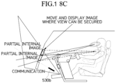
- FIG. 13C illustrates a situation in which a driver is seated on the right front seat of the vehicle, and a passenger (kid) is seated on the left front seat of the vehicle.
- FIG. 13A illustrates the occupants' views and a situation in which the dashboard is disposed over the floor within the vehicle, the cockpit is disposed over the dashboard, and image contents are displayed on a preset area (internal display area) within the windshield.
- the internal display area is divided into a preset number of partial areas (e.g. three areas in FIG. 13A , 13B , 13C ), and the cockpit has an adjustable height.
- the internal display area is divided into a first area (cluster information display), a second area (navigation information display) and a third area (image contents display for passenger) from the front of the driver seat toward the passenger seat.
- FIGS. 13B and 13C illustrate a situation in which an adult is seated on the driver seat, and a kid (short person) is seated on the passenger seat.
- the cockpit has an adjustable height, and the projection area and the image position have been adjusted on the basis of the driver.
- the processor 430 transmits a command signal to lower the display position of image contents in the third area in consideration of the cockpit position information and the occupant information, such that the image contents of the third area are displayed on a partial area of the dashboard area.
- the kid as a passenger can easily watch the image contents of the third area at the adjusted position of the internal display area.
- the processor 430 may transmit a command signal to the actuator which changes the angle of the reflecting mirror, and control the projector to project the image contents onto the surface of an internal trim panel, such that the kid seated on the passenger seat can check the image contents.
- This process uses the principle that the display area is divided into the internal display area and the external display area, and an image projected from the inside is formed on the surface (display panel) such that the image contents can be checked from the opposite side (passenger position).
- the processor 430 may transmit a control signal to the electrochromic film of the windshield to change the transparency of an area whose position has been moved so that the image contents for a passenger no longer needs to be displayed, thereby additionally securing visibility for the outside.
- the image contents for a passenger and the size of the image contents for a passenger as well as the position of the image contents for a passenger can be changed, and each of the display areas can be independently controlled.
- the size of the initial projection image can be adjusted, and the contents can be changed through mirroring or independent screen configuration.
- FIG. 34A illustrates a default field of view and a projection position
- FIG. 34B illustrates a change in projection position when a kid is seated on the passenger seat.
- the reflecting mirror is provided as a pair of reflecting mirrors 530a and 530b. This configuration considers that the driver seat and the passenger seat can be changed, because the steering wheel is movable from the left front seat to the right front seat of the vehicle.
- the reflecting mirror is provided as first and second reflecting mirrors 530a and 530b installed in the driver seat and the passenger seat, and configured to adjust the contents area when the driver seat is changed as the steering wheel is moved from side to side.
- a dashboard 520 has a partial surface area made of a translucent material, and maintains an opaque exterior when there is no lighting.
- an internal image is projected onto the internal display area of the vehicle, and an external image (communication) is projected onto the external display area of the vehicle.
- the angle of the second reflecting mirror 530b is controlled in parallel to the projection direction, and the first and second reflecting mirrors 530a and 530b are mounted on areas which do not interfere with the internal image projection and the external image projection, respectively.
- the processor 430 transmits a driving command signal to an actuator connected to the second reflecting mirror 530b in consideration of the cockpit position adjustment information and the occupant information.
- the second reflecting mirror 530b driven by the actuator is rotated and unfolded to form a projection image of the image contents for a passenger on the dashboard 520 in front of the passenger seat (passenger seat contents image reflection).
- FIG. 15A illustrates that the first and second reflecting mirrors 530a and 530b are separately applied to the driver seat and the passenger seat, respectively, as described above.
- the position of the passenger seat is decided as the steering wheel is moved to the left or right.
- the processor 430 decides whether to display image contents for a passenger by rotating any one reflecting mirror to some extents, in consideration of the cockpit position information (the position information of the cockpit whose height has been adjusted) and the occupant information (the view information of the occupant), and transmits a driving command signal to the actuator to display the image contents.
- the second reflecting mirror 530b is rotated ( FIG. 15B ) when the right front seat of the vehicle is the passenger seat, and the first reflecting mirror 530a is rotated ( FIG. 15C ) when the left front seat of the vehicle is the passenger seat.
- a reflecting mirror 530 in accordance with the embodiment of the present disclosure is disposed on a sliding and rotating bar 540 which can be rotated and moved straight from side to side, and located at the opposite position of the steering wheel.
- the reflecting mirror 530 is located at the right front seat of the vehicle, and when the steering wheel is moved to the right front seat of the vehicle as illustrated in FIG. 36B, the reflecting mirror 530 is moved to the left front seat of the vehicle by the sliding and rotating bar 540.
- the processor 430 transmits a driving command signal to rotate the reflecting mirror 530 by using the cockpit position information and the occupant information, and displays the image contents for a passenger on the dashboard as described above.
- FIG. 17A illustrates that a driver and a passenger (adult), who have a similar eye height, are seated in the vehicle
- FIG. 17B illustrates that a driver and a passenger who is taller than the driver are seated in the vehicle
- FIG. 17C illustrates that a driver and a passenger who is shorter than the driver are seated in the vehicle.
- the position of a contents display area for a passenger in the internal display area is adjusted.
- the display position of the internal display area is moved to a higher position than the existing position thereof.
- the processor 430 transmits a command signal to lift the contents display area for a passenger.
- the processor 430 transmits the control command signal to lift the display area of the third area.
- the processor 430 transmits the control signal to the electrochromic film of the windshield, such that the color of the area on which the image contents for a passenger are no longer displayed due to the position movement is changed to a transparent color, thereby additionally securing the visibility for the outside.
- FIG. 18A is a front view illustrating the positions of the first and second reflecting mirrors 530a and 530b.
- FIG. 18B illustrates that the position of the windshield and the image area of the dashboard cannot be checked from a passenger's view due to an image blocking area.
- the second reflecting mirror 530b is not rotated but fixed, and only the image area (third area) is adjusted to change and display image contents, such that the image contents are moved to and displayed on an area where the passenger's view can be secured.
- an electrochromic film is disposed on the image display area of a windshield 550, and an electrochromic section is subdivided so that transparent/opaque positions are adjusted in connection with contents control.
- the concentration of each section can be adjusted, and an image is outputted onto the section whose concentration has been adjusted, through the projector or the like.
- the partial area when the position of a partial area of a projection image is moved within the windshield as described above, the partial area may be changed to an empty space and become transparent to secure the visibility to the outside.
- FIG. 20 is a diagram illustrating an occupant recognition-based image display control method in accordance with an embodiment of the present disclosure.
- the occupant recognition-based image display control method in accordance with the embodiment of the present disclosure includes step S410 of receiving occupant state information of a driver and a passenger within a vehicle, step S420 of adjusting a reflecting mirror by using the occupant state information, or adjusting the display position of a display area within the vehicle, and step S430 of displaying image contents at the decided position.
- step S410 the occupant state information including at least any one of the eye positions and the head positions of the driver and the passenger is received.
- step S420 a command signal for adjusting the reflecting mirror is transmitted to lower a partial area of the display area within the vehicle by using the occupant state information.
- step S430 as the reflecting mirror is rotated, a projection image based on image contents for a passenger is displayed on a dashboard area.
- step S420 the display position of the partial area of the display area within the vehicle is lifted to an area where the passenger's view is not blocked, on the basis of the occupant state information.
- step S410 adjustment information on a cockpit having an adjustable height is further received.
- step S420 the display position of the display area within the vehicle is adjusted on the basis of the adjustment information and the occupant state information.
- the occupant recognition-based image display control method in accordance with the embodiment of the present disclosure further includes a step of transmitting a control signal to change the transparency of an electrochromic film of an area on which image contents have been displayed, when the area is changed to an empty space.
- the occupant recognition-based image display control method in accordance with the embodiment of the present disclosure may be implemented in a computer system or recorded in a recording medium.
- the computer system may include one or more processors, a memory, a user input device, a data communication bus, a user output device and a storage place.
- the above-described components perform data communication through the data communication bus.
- the computer system may further include a network interface coupled to a network.
- the processor may be a CPU (Central Processing Unit), or a semiconductor device configured to process a command stored in the memory and/or the storage place.
- CPU Central Processing Unit
- semiconductor device configured to process a command stored in the memory and/or the storage place.
- the memory and the storage place may include various types of volatile or nonvolatile storage media.
- the memory may include ROM and RAM.
- the occupant recognition-based image display control method in accordance with the embodiment of the present disclosure may be implemented as a method which can be executed in a computer.
- computer-readable commands may perform the occupant recognition-based image display control method in accordance with the embodiment of the present disclosure.
- the occupant recognition-based image display control method in accordance with the embodiment of the present disclosure may be implemented as computer-readable codes in a computer-readable recording medium.
- the computer-readable recording medium includes all types of recording media storing data which can be decoded by a computer system. Examples of the computer-readable recording media may include a ROM, RAM, magnetic tape, magnetic disk, flash memory, optical data storage device and the like. Furthermore, the computer-readable recording media are may be stored and executed as codes which are distributed to computer systems connected through a computer communication network and read in a distributed manner.
Landscapes
- Engineering & Computer Science (AREA)
- Mechanical Engineering (AREA)
- Chemical & Material Sciences (AREA)
- Combustion & Propulsion (AREA)
- Transportation (AREA)
- Fittings On The Vehicle Exterior For Carrying Loads, And Devices For Holding Or Mounting Articles (AREA)
- Instrument Panels (AREA)
- Steering Controls (AREA)
Description
- This application claims the benefit of
Korean Patent Application No. 10-2021-0018691, filed on February 9, 2021 - The present disclosure relates to a steering apparatus of a smart mobility vehicle.
- A smart mobility is an intellectualized means of transportation. Since the smart mobility uses electricity as a main power source, the smart mobility generates no exhaust gas. Thus, much attention is being paid to the smart mobility as a next generation means of transportation.
- In the related art, however, when an image is displayed at fixed position, an occupant's view may be blocked depending on the build/position of the occupant (including a driver and a passenger). In this case, the occupant may not normally recognize information displayed in the image.
- Furthermore, since a steering wheel which is adjusted in a top-to-bottom direction according to the build/position of the occupant has a limit within a fixed cockpit, there are difficulties in improving driving convenience only by adjusting the steering wheel.
-
EP 3 712 035 A2claim 1. - This Summary is provided to introduce a selection of concepts in simplified form that are further described below in the Detailed Description. This Summary is not intended to identify key features or essential features of the claimed subject matter, nor is it intended to be used as an aid in determining the scope of the claimed subject matter.
- In one general aspect, a steering apparatus of a smart mobility vehicle includes: a cockpit module disposed in front of a driver seat and a passenger seat within a vehicle; a steering wheel part connected to the cockpit module, and configured to be switchable between a position toward the driver seat and a position toward the passenger seat in a longitudinal direction of the cockpit module; and a locking part configured to fix the steering wheel part according to a preset condition. The cockpit module includes a first flat section disposed in front of the driver seat and a second flat section disposed in front of the passenger seat; and a locking section curved upward to connect the first flat section and the second flat section.
- When the steering wheel part passes through the locking section while the position of the steering wheel part is switched, the rotation of the steering wheel part may be restricted.
- The steering wheel part may have a portable terminal holding space, and a portable terminal may be paired with the vehicle through a vehicle control-related application installed in the portable terminal, when the portable terminal is held on the holding space.
- The steering wheel part may include: a base plate configured to be movable from side to side along the cockpit module; a casing connected to the rear of the base plate and bent upward; a lever configured to be interlocked with the locking part, and protruding from a part of a bottom of the casing; and a steering wheel connected to a rear of the casing.
- The base plate may be connected to the rail bracket and configured to be moveable on the rail bracket along the longitudinal direction of the cockpit module.
- The steering wheel may have a function button part configured in a paddle shift type to control a locking operation of the locking part.
- The steering wheel may include: a center part steerably connected to the rear of the casing, and configured to define a holding space for holding a portable terminal; and a grip part formed at an end of the center part, and configured to provide a finger grip space of a user.
- The center part may be electrically connected to the vehicle, such that the vehicle is automatically paired with the portable terminal according to preset terminal information, when the portable terminal is held.
- Other features and aspects will be apparent from the following detailed description, the drawings, and the claims.
-
-
FIGS. 1 and 2 are diagrams schematically illustrating a steering wheel part, whose position can be switched between a driver seat and a passenger seat, in a steering device of the smart mobility vehicle in accordance with the embodiment of the present disclosure. -
FIG. 3 is a diagram schematically illustrating the steering device in the smart mobility vehicle in accordance with the embodiment of the present disclosure. -
FIG. 4 is a cross-sectional view taken along line B-B' ofFIG. 3 . -
FIG. 5 is a diagram illustrating the operation relationships among components of the steering device in the smart mobility vehicle in accordance with the embodiment of the present disclosure. -
FIG. 6 is a diagram partially illustrating the operation relationships among the components of the steering device in the smart mobility vehicle in accordance with the embodiment of the present disclosure. -
FIGS. 7 and8 are diagrams schematically illustrating a steering wheel in the steering device of the smart mobility vehicle in accordance with the embodiment of the present disclosure. -
FIGS. 9 and 10 are diagrams schematically illustrating the prototype of the steering wheel in the steering device of the smart mobility vehicle in accordance with the embodiment of the present disclosure. -
FIG. 11 is a diagram illustrating an occupant recognition-based image display control device of the smart mobility vehicle in accordance with the embodiment of the present disclosure. -
FIG. 12 is a diagram illustrating an occupant sensing process in the smart mobility vehicle in accordance with the embodiment of the present disclosure. -
FIGS. 13A ,13B ,13C ,14A ,14B, 15A ,15B ,15C ,16A ,16B ,16C ,16D ,17A ,17B ,18A ,18B ,18C ,19A and19B are diagrams illustrating that the position of an image is moved in the smart mobility vehicle in accordance with the embodiment of the present disclosure. -
FIG. 20 is a flowchart illustrating an occupant recognition-based image display control method of the smart mobility vehicle in accordance with the embodiment of the present disclosure. - The advantages and characteristics of the present disclosure and a method for achieving the advantages and characteristics will be clearly understood through embodiments to be described below in detail with reference to the accompanying drawings. However, the present disclosure are not limited by the embodiments disclosed below, and may be embodied in various different forms. These embodiments are provided to make this disclosure thorough and complete and to fully convey the scope of the present disclosure to those skilled in the art to which the present disclosure pertains. The present disclosure is only defined by claims. Terms used in this specification are used for describing exemplary embodiments while not limiting the present disclosure. The terms of a singular form may include plural forms unless referred to the contrary. The term such as "comprise" or "comprising" used in the specification specifies a component, step, operation and/or element, but does not exclude the presence or addition of other components, steps, operations and/or elements. It should anyway be understood that the scope of protection of the present invention is defined by the appended claims.
- Hereafter, a projection device, a cockpit moving structure, a steering device, and an occupant recognition-based image display control device and method of a smart mobility device in accordance with an embodiment of the present disclosure will be described. Embodiments in accordance with the devices and structures may be carried out on the basis of the smart mobility vehicle.
- Hereafter, exemplary embodiments of the present disclosure will be described in detail with reference to the accompanying drawings.
-
FIGS. 1 and 2 schematically illustrate a steering wheel part whose position can be switched between a driver seat and a passenger seat, in a steering device of the smart mobility vehicle in accordance with the embodiment of the present disclosure. - Referring to
FIGS. 1 and 2 , the steering device of the smart mobility vehicle includes acockpit module 310, asteering wheel part 320 and alocking part 330. - The
cockpit module 310 is located in front of the driver seat and the passenger seat within the vehicle. Such acockpit module 310 includes arail bracket 311 including a firstflat section 311a, a secondflat section 311c, and alocking section 311b. The first and secondflat sections locking section 311b is curved upward and serves to connect the first and secondflat sections - The
locking section 311b has first and second inclined sections and formed at both ends thereof, and the first and second inclined sections and are engaged with thesteering wheel part 320 so as to restrict the rotation of thesteering wheel part 320. - The
steering wheel part 320 is connected to thecockpit module 310, such that the position thereof can be switched toward the driver seat or the passenger seat in the longitudinal direction of thecockpit module 310. - When the
steering wheel part 320 passes through thelocking section 311b as the position thereof is switched by a user's manipulation, the rotation of thesteering wheel part 320 needs to be restricted. This is in order to improve the driving safety of the vehicle. - The
locking part 330 fixes thesteering wheel part 320 according to a preset condition. The preset condition indicates optimal reference data considering the stopping and parking states of the smart mobility vehicle, information on whether the driving road corresponds to a straight section, and the driving safety. - Here, driving road determination logic monitors the road condition ahead through a radar or lidar, and determines that the
steering wheel part 320 can be switched from side to side, when the corresponding road is a straight section. At this time, thesteering wheel part 320 may be automatically and/or manually unlocked through the lockingpart 330. -
FIG. 3 is a diagram schematically illustrating the steering device in the smart mobility vehicle in accordance with the embodiment of the present disclosure,FIG. 4 is a cross-sectional view taken along line B-B' ofFIG. 3 , andFIGS. 5 and6 are diagrams each illustrating the operation relationships among the components of the steering device. - The
steering wheel part 320 illustrated inFIGS. 3 to 6 can be locked or rotated through a paddle shift type of steel wire connection. Thesteering wheel part 320 includes abase plate 321, acasing 322, alever 323 and asteering wheel 324. - The
base plate 321 can be moved from side to side along thecockpit module 310. That is, thebase plate 321 is connected so as to be movable on a plurality of rail brackets (311 of FIG. 22) formed in the longitudinal direction of thecockpit module 310. - The
casing 322 is connected to the rear of thebase plate 321 so as to be bent upward. Such acasing 322 has aconnector 322a embedded therein. - The
lever 323 has a structure which is interlocked with the lockingpart 330, and protrudes from a part of the bottom of thecasing 322. - The
steering wheel 324 is connected to the rear of thecasing 322. - The mechanical locking structure of the
steering wheel part 320 will be described with reference toFIG. 4 . The lockingpart 330 includes a fixingmember 331 and awire 332. The fixingmember 331 is moved upward and downward on thebase plate 321, and fixes or releases thesteering wheel part 320 to or from thecockpit module 310, and thewire 332 connects the fixingmember 331 and theconnector 322a of thecasing 322. - When the
lever 323 is pulled to the rear (toward the driver seat), theconnector 322a interlocked with thelever 323 pulls thewire 332 to the rear, and the fixingmember 331 connected to thewire 332 is moved upward to unlock thesteering wheel part 320. - At this time, the
steering wheel part 320 may be unlocked from thecockpit module 310 through an electric method using a solenoid or actuator, not the mechanical method. - For example, the
steering wheel part 320 may be unlocked through a simple button operation, or unlocked according to a preset condition while connected to smart devices (e.g. portable terminals or the like) of the occupants on a driver seat and a passenger seat. Thesteering wheel 324 of thesteering wheel part 320 may be moved by a predetermined distance through position switching, and then locked as in the initial state. -
FIGS. 7 and8 are diagrams schematically illustrating the steering wheel in the steering device of the smart mobility vehicle in accordance with the embodiment of the present disclosure. - Referring to
FIGS. 7 and8 , thesteering wheel 324 includes agrip part 324a, afunction button part 324b, acenter part 324c, asupport part 324d, a fixingpart 324e, and ahazard switch 324f. - The
steering wheel 324 may include thefunction button part 324b configured in a paddle shift type so as to control the locking operation of the locking part (330 ofFIG. 4 ). - The
center part 324c is steerably connected to the rear of the casing (322 ofFIG. 4 ), and provides a holding space for holding aportable terminal 20. When theportable terminal 20 is held on the holding space of thecenter part 324c, theportable terminal 20 may be paired with the vehicle through a vehicle control-related application installed in theportable terminal 20. Through the pairing, a user (including an occupant) may select a desired option by touching theportable terminal 20 with thesteering wheel 324 held on the user's hand. Thegrip part 324a is formed at either end of thecenter part 324c, and provides a finger grip space of the user. - At this time, the
center part 324c is electrically (in a wired/wireless manner) connected to the smart mobility vehicle. When theportable terminal 20 is held on the holding space, theportable terminal 20 may be automatically paired with the smart mobility vehicle according to preset terminal information. - The
support part 324d is disposed at the bottom of thecenter part 324c, and supports theportable terminal 20. - The fixing
part 324e is disposed between either end of thecenter part 324c and thegrip part 324a, and fixes theportable terminal 20. At this time, the fixingpart 324e may be formed in a hinge-connected clamp type, or have a separate buffer member (not illustrated) disposed in a section where the fixingpart 324e comes into contact with theportable terminal 20, in order to fix theportable terminal 20. - The
steering wheel 324 illustrated inFIG. 8 has the following dimensional information: the side-to-side length of thesteering wheel 324 is about 196 mm, the distance between one end of thesupport part 324d and theleft grip part 324a ranges from 110 to 120 mm, and the distance between the other end of thesupport part 324d and theright grip part 324a ranges from 110 to 120 mm. - Here, the side-to-side length of the
support part 324d may be about 70 mm. The dimensional information between the components of thesteering wheel 324 illustrated inFIG. 8 is only an example, and the present disclosure is not limited to such numerical values. However, the dimension ratio between the corresponding components may be significant. -
FIGS. 9 and 10 schematically show the prototype of the steering wheel in the steering device of the smart mobility vehicle in accordance with the embodiment of the present disclosure. - The
steering wheel 324 illustrated inFIGS. 9 and 10 may be a steering wheel which is manufactured in a prototype in consideration of a grip condition of thesteering wheel 324 during driving and a condition in which a user can manipulate the screen of a portable terminal. - Under the corresponding condition, the following consideration needs to be taken into account: the user needs to easily touch or manipulate the screen of the portable terminal by using his/her thumb with the
steering wheel 324 held by the user's hand. - Furthermore, the grip part (324a of
FIG. 7 ) of thesteering wheel 324 needs to enable the user to easily grip the portable terminal placed on the center part (324c ofFIG. 7 ). The dimensional information of the steering wheel based on the corresponding condition may be set to the values illustrated in FIG. 28. As described above, the present disclosure is not limited to the dimensional information, but the dimension ratio between the corresponding components may be significant. - The arrangement of function buttons on an application within the portable terminal may be changed according to a user's settings, such that the user easily manipulates the portable terminal with the portable terminal placed on the
steering wheel 324. -
FIG. 11 is a diagram illustrating an occupant recognition-based image display control device in accordance with an embodiment of the present disclosure. - The occupant recognition-based image display control device in accordance with the embodiment of the present disclosure includes an
input unit 410, amemory 420 and aprocessor 430. Theinput unit 410 is configured to receive occupant recognition information, thememory 420 is configured to store a program for controlling an image display within the vehicle by using the occupant recognition information, and theprocessor 430 is configured to execute the program. Theprocessor 430 transmits a command signal to change a partial area of an image display area within the vehicle to an area which does not block an occupant's view, by using the occupant recognition information. - The
input unit 410 receives the occupant recognition information including one or more of the eye position and the head position of an occupant. - The
processor 430 transmits a command signal for lowering the partial area by using the occupant recognition information. - The
processor 430 transmits a driving command signal to an actuator connected to a reflecting mirror, and rotates the reflecting mirror such that a projection image based on image contents for a passenger is formed on the dashboard area. - When the difference between the eye or head positions of the driver and the passenger is out of a preset range, the
processor 430 transmits the command signal to lift the partial area. - The
input unit 410 receives information related to the state in which the height of a cockpit is adjusted, and theprocessor 430 transmits the command signal to adjust the partial area of the image display area within the vehicle by using the occupant recognition information and the information related to the state in which the height of the cockpit is adjusted. - The
processor 430 transmits an electrochromic film control signal to adjust the transparency of an empty space which occurs as the partial area of the image display area within the vehicle is changed. -
FIG. 12 illustrates an occupant sensing process in accordance with an embodiment of the present disclosure. - Referring to
FIG. 12 , the eye position or body (head) position of an occupant is sensed by an in-vehicle monitoring device 510 such as an IR camera or ToF camera. - The
processor 430 receives information on the eye position or body position of the occupant as occupant information, and transmits a display position adjustment-related command signal for the internal display in consideration of the occupant information. - The
processor 430 acquires information on the occupant's height when seated (sitting height), and the eye position and the FOV of the occupant, by using the occupant information. - Furthermore, the
processor 430 may receive occupant information from a separate sensor (e.g. a weight sensor mounted in a seat), and recognize whether the occupant is an adult or kid. - At this time, the
processor 430 decides display position coordinate information of the internal display according to the occupant information of each occupant and transmits a command signal, or transmits a command signal for display position coordinate information of the internal display based on a preset category to which the occupant information of each occupant belongs. - For example, suppose that the position of the partial area of the display area within the vehicle is adjusted, when the eye position of a passenger A is a position A-1 (1 m in a vertical direction z from a preset reference point within the vehicle) and the eye position of a passenger B is a position B-1 (0.8 m in the vertical direction z from the preset reference point within the vehicle). Hereafter, the position adjustment will be described in detail with reference to
FIGS. 7 to 9 . - For example, it is assumed that, when the eye position of a passenger corresponds to a preset position (e.g. 1 m or less in the vertical direction z from the preset reference point within the vehicle), the position of the partial area of the display area is adjusted in proportion to the eye position. In this case, a position adjustment reference value may be set to 5 cm.
- At this time, the center position of the above-described partial area in the case of the passenger A can be lifted by 5 cm from the existing display position, and the center position of the partial area in the case of the passenger B can be lifted by 6 cm from the existing display position.
- For another example, when a first classification in which the center position of the partial area is lifted by 5 cm from the display position in the case that the eye position of the passenger is 1 m or less in the vertical direction z from the preset reference point within the vehicle and a second classification in which the center position of the partial area is lifted by 7 cm from the display position in the case that the eye position of the passenger is 0.7 m or less in the vertical direction z from the preset reference point within the vehicle are set according to the eye position of the passenger, the
processor 430 determines that both of the passengers A and B correspond to the first classification, and lifts the center position of the partial area by 5 cm from the existing display position. - The
processor 430 transmits a command signal to adjust the display position of the internal display area in overall consideration of the height adjustment information of the cockpit and the occupant information. - That is, the
processor 430 determines whether the occupant's view is blocked, by using the occupant information and the height adjustment information of the cockpit, and transmits a command signal to adjust the display position of the partial area of the internal display area, according to the determination result. - The projector having received the command signal adjusts the display position of the partial area of the internal display area, or the actuator having received the command signal drives (rotates and unfolds) the reflecting mirror to adjust the area on which a projection image is formed.
- Furthermore, in order to prevent the driver's view from being blocked as the display position of image contents is adjusted, the
processor 430 sets a position adjustment limit value for the partial area of the internal display area, and transmits a command signal related to the display position adjustment. - For example, the height of the partial area of the internal display area in front of the passenger seat is set to a value that cannot rise to a preset limit value (e.g. 20 cm) or more.
-
FIGS. 13 to 19 illustrate that the position of an image is moved, in the smart mobility vehicle in accordance with the embodiment of the present disclosure -
FIG. 13A illustrates a situation in which a driver is seated on the left front seat of the vehicle, and a passenger (adult) is seated on the right front seat of the vehicle. -
FIG. 13B illustrates a situation in which a driver is seated on the left front seat of the vehicle, and a passenger (kid) is seated on the right front seat of the vehicle. -
FIG. 13C illustrates a situation in which a driver is seated on the right front seat of the vehicle, and a passenger (kid) is seated on the left front seat of the vehicle. -
FIG. 13A illustrates the occupants' views and a situation in which the dashboard is disposed over the floor within the vehicle, the cockpit is disposed over the dashboard, and image contents are displayed on a preset area (internal display area) within the windshield. - At this time, the internal display area is divided into a preset number of partial areas (e.g. three areas in
FIG. 13A ,13B ,13C ), and the cockpit has an adjustable height. - Suppose that the internal display area is divided into a first area (cluster information display), a second area (navigation information display) and a third area (image contents display for passenger) from the front of the driver seat toward the passenger seat.
-
FIGS. 13B and13C illustrate a situation in which an adult is seated on the driver seat, and a kid (short person) is seated on the passenger seat. - As described above, it is assumed that the cockpit has an adjustable height, and the projection area and the image position have been adjusted on the basis of the driver.
- At this time, the
processor 430 transmits a command signal to lower the display position of image contents in the third area in consideration of the cockpit position information and the occupant information, such that the image contents of the third area are displayed on a partial area of the dashboard area. Thus, the kid as a passenger can easily watch the image contents of the third area at the adjusted position of the internal display area. - At this time, as will be described below, the
processor 430 may transmit a command signal to the actuator which changes the angle of the reflecting mirror, and control the projector to project the image contents onto the surface of an internal trim panel, such that the kid seated on the passenger seat can check the image contents. - This process uses the principle that the display area is divided into the internal display area and the external display area, and an image projected from the inside is formed on the surface (display panel) such that the image contents can be checked from the opposite side (passenger position).
- As illustrated in
FIGS. 13B and13C , theprocessor 430 may transmit a control signal to the electrochromic film of the windshield to change the transparency of an area whose position has been moved so that the image contents for a passenger no longer needs to be displayed, thereby additionally securing visibility for the outside. - The image contents for a passenger and the size of the image contents for a passenger as well as the position of the image contents for a passenger can be changed, and each of the display areas can be independently controlled.
- In accordance with the embodiment of the present disclosure, the size of the initial projection image can be adjusted, and the contents can be changed through mirroring or independent screen configuration.
- FIG. 34A illustrates a default field of view and a projection position, and FIG. 34B illustrates a change in projection position when a kid is seated on the passenger seat.
- The reflecting mirror is provided as a pair of reflecting
mirrors - That is, the reflecting mirror is provided as first and second reflecting
mirrors - Referring to
FIGS. 14A and14B , adashboard 520 has a partial surface area made of a translucent material, and maintains an opaque exterior when there is no lighting. - Referring to
FIG. 14A , an internal image is projected onto the internal display area of the vehicle, and an external image (communication) is projected onto the external display area of the vehicle. - In the case of the default field of view illustrated in
FIG. 14A , the angle of the second reflectingmirror 530b is controlled in parallel to the projection direction, and the first and second reflectingmirrors - When a kid is seated on the passenger seat as illustrated in
FIG. 14B , theprocessor 430 transmits a driving command signal to an actuator connected to the second reflectingmirror 530b in consideration of the cockpit position adjustment information and the occupant information. - The second reflecting
mirror 530b driven by the actuator is rotated and unfolded to form a projection image of the image contents for a passenger on thedashboard 520 in front of the passenger seat (passenger seat contents image reflection). -
FIG. 15A illustrates that the first and second reflectingmirrors - As illustrated in
FIGS. 15B and15C , the position of the passenger seat is decided as the steering wheel is moved to the left or right. When a passenger seated on the passenger seat is a kid, theprocessor 430 decides whether to display image contents for a passenger by rotating any one reflecting mirror to some extents, in consideration of the cockpit position information (the position information of the cockpit whose height has been adjusted) and the occupant information (the view information of the occupant), and transmits a driving command signal to the actuator to display the image contents. - As the actuator is driven, the second reflecting
mirror 530b is rotated (FIG. 15B ) when the right front seat of the vehicle is the passenger seat, and the first reflectingmirror 530a is rotated (FIG. 15C ) when the left front seat of the vehicle is the passenger seat. - Referring to
FIGS. 16A to 16D , a reflectingmirror 530 in accordance with the embodiment of the present disclosure is disposed on a sliding androtating bar 540 which can be rotated and moved straight from side to side, and located at the opposite position of the steering wheel. - That is, when the steering wheel is disposed at the left front seat of the vehicle as illustrated in
FIG. 16A , the reflectingmirror 530 is located at the right front seat of the vehicle, and when the steering wheel is moved to the right front seat of the vehicle as illustrated in FIG. 36B, the reflectingmirror 530 is moved to the left front seat of the vehicle by the sliding androtating bar 540. - When a kid is seated on the passenger seat as illustrated in
FIGS. 16C and 36D, theprocessor 430 transmits a driving command signal to rotate the reflectingmirror 530 by using the cockpit position information and the occupant information, and displays the image contents for a passenger on the dashboard as described above. -
FIG. 17A illustrates that a driver and a passenger (adult), who have a similar eye height, are seated in the vehicle,FIG. 17B illustrates that a driver and a passenger who is taller than the driver are seated in the vehicle, andFIG. 17C illustrates that a driver and a passenger who is shorter than the driver are seated in the vehicle. - Referring to
FIGS. 17A and17B , when the difference between the eye positions or head positions of the driver and the passenger falls within a preset range, the internal display area is maintained. - Referring to
FIG. 17C , when the passenger is shorter than the driver such that the difference between the eye positions or head positions of the driver and the passenger is out of the preset range, the position of a contents display area for a passenger in the internal display area is adjusted. - In accordance with the embodiment of the present disclosure, when the position of the cockpit having an adjustable height is changed to a higher position than the existing position thereof because a tall driver is seated in the vehicle, the display position of the internal display area is moved to a higher position than the existing position thereof. Thus, since the view of the passenger shorter than the driver is blocked with respect to the contents display area for a passenger, the
processor 430 transmits a command signal to lift the contents display area for a passenger. - That is, when the passenger is shorter than the driver such that the third area is blocked by the cockpit, the
processor 430 transmits the control command signal to lift the display area of the third area. - At this time, as described above with reference to
FIGS. 13B and13C , theprocessor 430 transmits the control signal to the electrochromic film of the windshield, such that the color of the area on which the image contents for a passenger are no longer displayed due to the position movement is changed to a transparent color, thereby additionally securing the visibility for the outside. -
FIG. 18A is a front view illustrating the positions of the first and second reflectingmirrors FIG. 18B illustrates that the position of the windshield and the image area of the dashboard cannot be checked from a passenger's view due to an image blocking area. - That is, when the image contents for a passenger are displayed on the third area covered by the cockpit because the passenger is shorter than the driver, the third area is partially lifted, and the image contents are lifted and displayed.
- At this time, as illustrated in
FIG. 18C , the second reflectingmirror 530b is not rotated but fixed, and only the image area (third area) is adjusted to change and display image contents, such that the image contents are moved to and displayed on an area where the passenger's view can be secured. - Referring to
FIG. 19A , an electrochromic film is disposed on the image display area of awindshield 550, and an electrochromic section is subdivided so that transparent/opaque positions are adjusted in connection with contents control. - As the electrochromic film has a power application section subdivided into a plurality of sections, the concentration of each section can be adjusted, and an image is outputted onto the section whose concentration has been adjusted, through the projector or the like.
- Referring to
FIG. 19B , when the position of a partial area of a projection image is moved within the windshield as described above, the partial area may be changed to an empty space and become transparent to secure the visibility to the outside. -
FIG. 20 is a diagram illustrating an occupant recognition-based image display control method in accordance with an embodiment of the present disclosure. - The occupant recognition-based image display control method in accordance with the embodiment of the present disclosure includes step S410 of receiving occupant state information of a driver and a passenger within a vehicle, step S420 of adjusting a reflecting mirror by using the occupant state information, or adjusting the display position of a display area within the vehicle, and step S430 of displaying image contents at the decided position.
- In step S410, the occupant state information including at least any one of the eye positions and the head positions of the driver and the passenger is received.
- In step S420, a command signal for adjusting the reflecting mirror is transmitted to lower a partial area of the display area within the vehicle by using the occupant state information.
- In step S430, as the reflecting mirror is rotated, a projection image based on image contents for a passenger is displayed on a dashboard area.
- In step S420, the display position of the partial area of the display area within the vehicle is lifted to an area where the passenger's view is not blocked, on the basis of the occupant state information.
- In step S410, adjustment information on a cockpit having an adjustable height is further received. In step S420 , the display position of the display area within the vehicle is adjusted on the basis of the adjustment information and the occupant state information.
- The occupant recognition-based image display control method in accordance with the embodiment of the present disclosure further includes a step of transmitting a control signal to change the transparency of an electrochromic film of an area on which image contents have been displayed, when the area is changed to an empty space.
- The occupant recognition-based image display control method in accordance with the embodiment of the present disclosure may be implemented in a computer system or recorded in a recording medium. The computer system may include one or more processors, a memory, a user input device, a data communication bus, a user output device and a storage place. The above-described components perform data communication through the data communication bus.
- The computer system may further include a network interface coupled to a network. The processor may be a CPU (Central Processing Unit), or a semiconductor device configured to process a command stored in the memory and/or the storage place.
- The memory and the storage place may include various types of volatile or nonvolatile storage media. For example, the memory may include ROM and RAM.
- Therefore, the occupant recognition-based image display control method in accordance with the embodiment of the present disclosure may be implemented as a method which can be executed in a computer. When the occupant recognition-based image display control method in accordance with the embodiment of the present disclosure is performed in a computer device, computer-readable commands may perform the occupant recognition-based image display control method in accordance with the embodiment of the present disclosure.
- The occupant recognition-based image display control method in accordance with the embodiment of the present disclosure may be implemented as computer-readable codes in a computer-readable recording medium. The computer-readable recording medium includes all types of recording media storing data which can be decoded by a computer system. Examples of the computer-readable recording media may include a ROM, RAM, magnetic tape, magnetic disk, flash memory, optical data storage device and the like. Furthermore, the computer-readable recording media are may be stored and executed as codes which are distributed to computer systems connected through a computer communication network and read in a distributed manner.
Claims (8)
- A steering apparatus of a smart mobility vehicle, comprising:a cockpit module (310) disposed in front of a driver seat and a passenger seat within a vehicle;a steering wheel part (320) connected to the cockpit module (310), and configured to be switchable between a position toward the driver seat and a position toward the passenger seat in a longitudinal direction of the cockpit module (310); anda locking part (330) configured to fix the steering wheel part (320) according to a preset condition,wherein the cockpit module (310) comprises a rail bracket (311),characterized in that the rail bracket (311) includes:a first flat section (311a) disposed in front of the driver seat and a second flat section (311c) disposed in front of the passenger seat; anda locking section (311b) curved upward to connect the first flat section (311a) and the second flat section (311c).
- The steering apparatus of claim 1, wherein when the steering wheel part (320) passes through the locking section (311c) while the position of the steering wheel part (320) is switched, the rotation of the steering wheel part (320) is restricted.
- The steering apparatus of claim 1, or 2, wherein the steering wheel part (320) comprises a portable terminal holding space, and a portable terminal is paired with the vehicle through a vehicle control-related application installed in the portable terminal, when the portable terminal is held on the holding space.
- The steering apparatus of claim 1, 2, or 3, wherein the steering wheel part (320) comprises:a base plate (321) configured to be movable from side to side along the cockpit module (310);a casing (322) connected to the rear of the base plate and bent upward;a lever (323) configured to be interlocked with the locking part (330), and protruding from a part of a bottom of the casing (322); anda steering wheel (324) connected to a rear of the casing (322).
- The steering apparatus of claim 4, wherein the base plate (321) is connected to the rail bracket (311) and configured to be moveable on the rail bracket (311) along the longitudinal direction of the cockpit module (310).
- The steering apparatus of claim 4, or 5, wherein the steering wheel (324) comprises a function button part (324b) configured in a paddle shift type to control a locking operation of the locking part (330).
- The steering apparatus of claim 4, 5, or 6, wherein the steering wheel (324) comprises:a center part (324c) steerably connected to the rear of the casing (322), and configured to define a holding space for holding a portable terminal; anda grip part (324a) formed at an end of the center part (324c), and configured to provide a finger grip space of a user.
- The steering apparatus of claim 7, wherein the center part (324c) is electrically connected to the vehicle, such that the vehicle is automatically paired with the portable terminal according to preset terminal information, when the portable terminal is held.
Applications Claiming Priority (1)
| Application Number | Priority Date | Filing Date | Title |
|---|---|---|---|
| KR1020210018691A KR20220114999A (en) | 2021-02-09 | 2021-02-09 | Steering apparatus comprising steering wheel of smart mobility vehicle |
Publications (3)
| Publication Number | Publication Date |
|---|---|
| EP4039561A2 EP4039561A2 (en) | 2022-08-10 |
| EP4039561A3 EP4039561A3 (en) | 2022-11-02 |
| EP4039561B1 true EP4039561B1 (en) | 2024-05-29 |
Family
ID=80446752
Family Applications (1)
| Application Number | Title | Priority Date | Filing Date |
|---|---|---|---|
| EP22155875.2A Active EP4039561B1 (en) | 2021-02-09 | 2022-02-09 | Steering apparatus including steering wheel of smart mobility vehicle |
Country Status (4)
| Country | Link |
|---|---|
| US (1) | US11667324B2 (en) |
| EP (1) | EP4039561B1 (en) |
| KR (1) | KR20220114999A (en) |
| CN (1) | CN114906205B (en) |
Families Citing this family (5)
| Publication number | Priority date | Publication date | Assignee | Title |
|---|---|---|---|---|
| DE102020215759A1 (en) * | 2020-12-11 | 2022-06-15 | Thyssenkrupp Ag | Steering column with controllable adjustability and method for operating such a steering column |
| US11827269B2 (en) * | 2021-03-31 | 2023-11-28 | Hyundai Mobis Co., Ltd. | Steering apparatus |
| US20240199143A1 (en) * | 2022-12-14 | 2024-06-20 | Cnh Industrial America Llc | Cab system for a vehicle |
| DE102023118320A1 (en) * | 2023-07-11 | 2025-01-16 | Bayerische Motoren Werke Aktiengesellschaft | Vehicle window with a switchable black print and a HUD for a vehicle that can be used inside and outside |
| CN119659487A (en) * | 2023-09-20 | 2025-03-21 | 奥特埃克斯股份有限公司 | Steering wheel hiding device and vehicle |
Family Cites Families (18)
| Publication number | Priority date | Publication date | Assignee | Title |
|---|---|---|---|---|
| US6857498B2 (en) * | 2002-07-25 | 2005-02-22 | General Motors Corporation | Console with driver's interface |
| ITTO20040130A1 (en) * | 2004-03-02 | 2004-06-02 | Italdesign Giugiaro Spa | ADJUSTABLE CONTROL GROUP AND ADAPTABLE SEAT FOR VEHICLE |
| US7363131B2 (en) * | 2004-06-16 | 2008-04-22 | Chrysler Llc | Re-positionable vehicle control-by-wire assembly, method, and system |
| JP2007071370A (en) * | 2005-09-09 | 2007-03-22 | Denso Corp | Vehicle control device |
| CN202896649U (en) * | 2012-04-28 | 2013-04-24 | 郭永胜 | Multifunctional steering wheel |
| DE102012010125A1 (en) * | 2012-05-23 | 2012-12-13 | Daimler Ag | Steering wheel of operating device for operating motor car, has control element that controls infotainment functions for operation of motor car and assigns user-defined control function as infotainment function for motor car operation |
| KR101475923B1 (en) * | 2013-12-24 | 2014-12-23 | 전자부품연구원 | Steering wheel system and control method of the mobile phone linkage |
| CN104442990A (en) * | 2014-11-26 | 2015-03-25 | 浙江大学 | Intelligent steering wheel of electric automobile |
| US9919724B2 (en) * | 2015-05-29 | 2018-03-20 | Steering Solutions Ip Holding Corporation | Retractable steering column with manual retrieval |
| GB2550610B (en) | 2016-05-25 | 2019-11-20 | Ford Global Tech Llc | A steering wheel assembly |
| DE102016210622A1 (en) | 2016-06-15 | 2017-12-21 | Bayerische Motoren Werke Aktiengesellschaft | Method for taking over the vehicle guidance of a motor vehicle |
| GB2552703B (en) * | 2016-08-04 | 2018-11-14 | Ford Global Tech Llc | A holographic display system |
| GB2552984B (en) * | 2016-08-17 | 2018-10-24 | Ford Global Tech Llc | An ultrasonic haptic control system |
| CN109383606B (en) * | 2018-12-17 | 2024-03-19 | 杭州金浪机电有限公司 | Functional steering wheel component for SUV |
| JP7140697B2 (en) * | 2019-03-04 | 2022-09-21 | 本田技研工業株式会社 | vehicle steering system |
| US11292504B2 (en) * | 2019-03-20 | 2022-04-05 | Volvo Car Corporation | Vehicle having multiple driving positions |
| US10562558B1 (en) * | 2019-04-09 | 2020-02-18 | Ford Global Technologies, Llc | Foldable steering wheel system |
| JP7217299B2 (en) * | 2021-01-27 | 2023-02-02 | 本田技研工業株式会社 | Head-up display control system and head-up display display method |
-
2021
- 2021-02-09 KR KR1020210018691A patent/KR20220114999A/en active Pending
-
2022
- 2022-02-09 CN CN202210123024.0A patent/CN114906205B/en active Active
- 2022-02-09 EP EP22155875.2A patent/EP4039561B1/en active Active
- 2022-02-09 US US17/667,712 patent/US11667324B2/en active Active
Also Published As
| Publication number | Publication date |
|---|---|
| EP4039561A2 (en) | 2022-08-10 |
| EP4039561A3 (en) | 2022-11-02 |
| CN114906205A (en) | 2022-08-16 |
| US11667324B2 (en) | 2023-06-06 |
| US20220371648A1 (en) | 2022-11-24 |
| CN114906205B (en) | 2023-12-01 |
| KR20220114999A (en) | 2022-08-17 |
Similar Documents
| Publication | Publication Date | Title |
|---|---|---|
| EP4039561B1 (en) | Steering apparatus including steering wheel of smart mobility vehicle | |
| JP2009184406A (en) | Head-up display device for vehicle | |
| EP1138551A2 (en) | Infrared communication system for a vehicle and vehicle accessory operation system that utilizes the communication system | |
| US20090128307A1 (en) | Display device and display method for a vehicle | |
| EP1228917A1 (en) | A control arrangement | |
| JP4858206B2 (en) | In-vehicle device operation support device and operation support method | |
| US8128232B2 (en) | Visible in-vehicle laser beam projector providing variable projection region as function of seatbelt fastening status | |
| US6529825B2 (en) | Voice guidance switching device and method | |
| EP4039521B1 (en) | Smart mobility vehicle | |
| US6882267B2 (en) | Device controller | |
| JPH11334493A (en) | Automotive input device | |
| CN118302321A (en) | Vehicles with foldable or rollable displays | |
| KR102933672B1 (en) | Apparatus and method for controlling display based on passenger recognition | |
| US20250214439A1 (en) | Display device and vehicle equipped with same | |
| JPH10278649A (en) | Adjustment devices in automobiles | |
| JP2003063275A (en) | Head-up display device | |
| EP2757407B1 (en) | Multiple-view display system with user recognition and operation method thereof | |
| EP3448723B1 (en) | Human-machine interface apparatus for a vehicle | |
| KR20220115002A (en) | Apparatus and method for controlling projection display | |
| KR102367942B1 (en) | Motion recognition apparatus for vehicles | |
| KR20220115005A (en) | Cockpit moving structure of smart mobility vehicle | |
| KR20220115000A (en) | Projection apparatus of smart mobility vehicle | |
| US20260062027A1 (en) | Vehicle notification device | |
| US20260001450A1 (en) | Vehicle control device | |
| KR102043998B1 (en) | Apparatus and method for controlling a smart mirror for a vehicle |
Legal Events
| Date | Code | Title | Description |
|---|---|---|---|
| PUAI | Public reference made under article 153(3) epc to a published international application that has entered the european phase |
Free format text: ORIGINAL CODE: 0009012 |
|
| STAA | Information on the status of an ep patent application or granted ep patent |
Free format text: STATUS: REQUEST FOR EXAMINATION WAS MADE |
|
| 17P | Request for examination filed |
Effective date: 20220309 |
|
| AK | Designated contracting states |
Kind code of ref document: A2 Designated state(s): AL AT BE BG CH CY CZ DE DK EE ES FI FR GB GR HR HU IE IS IT LI LT LU LV MC MK MT NL NO PL PT RO RS SE SI SK SM TR |
|
| PUAL | Search report despatched |
Free format text: ORIGINAL CODE: 0009013 |
|
| AK | Designated contracting states |
Kind code of ref document: A3 Designated state(s): AL AT BE BG CH CY CZ DE DK EE ES FI FR GB GR HR HU IE IS IT LI LT LU LV MC MK MT NL NO PL PT RO RS SE SI SK SM TR |
|
| RIC1 | Information provided on ipc code assigned before grant |
Ipc: B62D 1/18 20060101AFI20220928BHEP |
|
| RBV | Designated contracting states (corrected) |
Designated state(s): AL AT BE BG CH CY CZ DE DK EE ES FI FR GB GR HR HU IE IS IT LI LT LU LV MC MK MT NL NO PL PT RO RS SE SI SK SM TR |
|
| GRAP | Despatch of communication of intention to grant a patent |
Free format text: ORIGINAL CODE: EPIDOSNIGR1 |
|
| STAA | Information on the status of an ep patent application or granted ep patent |
Free format text: STATUS: GRANT OF PATENT IS INTENDED |
|
| INTG | Intention to grant announced |
Effective date: 20240119 |
|
| GRAS | Grant fee paid |
Free format text: ORIGINAL CODE: EPIDOSNIGR3 |
|
| GRAA | (expected) grant |
Free format text: ORIGINAL CODE: 0009210 |
|
| STAA | Information on the status of an ep patent application or granted ep patent |
Free format text: STATUS: THE PATENT HAS BEEN GRANTED |
|
| P01 | Opt-out of the competence of the unified patent court (upc) registered |
Effective date: 20240408 |
|
| AK | Designated contracting states |
Kind code of ref document: B1 Designated state(s): AL AT BE BG CH CY CZ DE DK EE ES FI FR GB GR HR HU IE IS IT LI LT LU LV MC MK MT NL NO PL PT RO RS SE SI SK SM TR |
|
| REG | Reference to a national code |
Ref country code: CH Ref legal event code: EP |
|
| REG | Reference to a national code |
Ref country code: IE Ref legal event code: FG4D |
|
| REG | Reference to a national code |
Ref country code: DE Ref legal event code: R096 Ref document number: 602022003617 Country of ref document: DE |
|
| REG | Reference to a national code |
Ref country code: LT Ref legal event code: MG9D |
|
| REG | Reference to a national code |
Ref country code: NL Ref legal event code: MP Effective date: 20240529 |
|
| PG25 | Lapsed in a contracting state [announced via postgrant information from national office to epo] |
Ref country code: IS Free format text: LAPSE BECAUSE OF FAILURE TO SUBMIT A TRANSLATION OF THE DESCRIPTION OR TO PAY THE FEE WITHIN THE PRESCRIBED TIME-LIMIT Effective date: 20240929 |
|
| PG25 | Lapsed in a contracting state [announced via postgrant information from national office to epo] |
Ref country code: BG Free format text: LAPSE BECAUSE OF FAILURE TO SUBMIT A TRANSLATION OF THE DESCRIPTION OR TO PAY THE FEE WITHIN THE PRESCRIBED TIME-LIMIT Effective date: 20240529 |
|
| PG25 | Lapsed in a contracting state [announced via postgrant information from national office to epo] |
Ref country code: HR Free format text: LAPSE BECAUSE OF FAILURE TO SUBMIT A TRANSLATION OF THE DESCRIPTION OR TO PAY THE FEE WITHIN THE PRESCRIBED TIME-LIMIT Effective date: 20240529 Ref country code: FI Free format text: LAPSE BECAUSE OF FAILURE TO SUBMIT A TRANSLATION OF THE DESCRIPTION OR TO PAY THE FEE WITHIN THE PRESCRIBED TIME-LIMIT Effective date: 20240529 |
|
| PG25 | Lapsed in a contracting state [announced via postgrant information from national office to epo] |
Ref country code: GR Free format text: LAPSE BECAUSE OF FAILURE TO SUBMIT A TRANSLATION OF THE DESCRIPTION OR TO PAY THE FEE WITHIN THE PRESCRIBED TIME-LIMIT Effective date: 20240830 |
|
| REG | Reference to a national code |
Ref country code: AT Ref legal event code: MK05 Ref document number: 1690406 Country of ref document: AT Kind code of ref document: T Effective date: 20240529 |
|
| PG25 | Lapsed in a contracting state [announced via postgrant information from national office to epo] |
Ref country code: ES Free format text: LAPSE BECAUSE OF FAILURE TO SUBMIT A TRANSLATION OF THE DESCRIPTION OR TO PAY THE FEE WITHIN THE PRESCRIBED TIME-LIMIT Effective date: 20240529 |
|
| PG25 | Lapsed in a contracting state [announced via postgrant information from national office to epo] |
Ref country code: AT Free format text: LAPSE BECAUSE OF FAILURE TO SUBMIT A TRANSLATION OF THE DESCRIPTION OR TO PAY THE FEE WITHIN THE PRESCRIBED TIME-LIMIT Effective date: 20240529 |
|
| PG25 | Lapsed in a contracting state [announced via postgrant information from national office to epo] |
Ref country code: PL Free format text: LAPSE BECAUSE OF FAILURE TO SUBMIT A TRANSLATION OF THE DESCRIPTION OR TO PAY THE FEE WITHIN THE PRESCRIBED TIME-LIMIT Effective date: 20240529 |
|
| PG25 | Lapsed in a contracting state [announced via postgrant information from national office to epo] |
Ref country code: LV Free format text: LAPSE BECAUSE OF FAILURE TO SUBMIT A TRANSLATION OF THE DESCRIPTION OR TO PAY THE FEE WITHIN THE PRESCRIBED TIME-LIMIT Effective date: 20240529 |
|
| PG25 | Lapsed in a contracting state [announced via postgrant information from national office to epo] |
Ref country code: PL Free format text: LAPSE BECAUSE OF FAILURE TO SUBMIT A TRANSLATION OF THE DESCRIPTION OR TO PAY THE FEE WITHIN THE PRESCRIBED TIME-LIMIT Effective date: 20240529 Ref country code: NO Free format text: LAPSE BECAUSE OF FAILURE TO SUBMIT A TRANSLATION OF THE DESCRIPTION OR TO PAY THE FEE WITHIN THE PRESCRIBED TIME-LIMIT Effective date: 20240829 Ref country code: LV Free format text: LAPSE BECAUSE OF FAILURE TO SUBMIT A TRANSLATION OF THE DESCRIPTION OR TO PAY THE FEE WITHIN THE PRESCRIBED TIME-LIMIT Effective date: 20240529 Ref country code: IS Free format text: LAPSE BECAUSE OF FAILURE TO SUBMIT A TRANSLATION OF THE DESCRIPTION OR TO PAY THE FEE WITHIN THE PRESCRIBED TIME-LIMIT Effective date: 20240929 Ref country code: HR Free format text: LAPSE BECAUSE OF FAILURE TO SUBMIT A TRANSLATION OF THE DESCRIPTION OR TO PAY THE FEE WITHIN THE PRESCRIBED TIME-LIMIT Effective date: 20240529 Ref country code: GR Free format text: LAPSE BECAUSE OF FAILURE TO SUBMIT A TRANSLATION OF THE DESCRIPTION OR TO PAY THE FEE WITHIN THE PRESCRIBED TIME-LIMIT Effective date: 20240830 Ref country code: FI Free format text: LAPSE BECAUSE OF FAILURE TO SUBMIT A TRANSLATION OF THE DESCRIPTION OR TO PAY THE FEE WITHIN THE PRESCRIBED TIME-LIMIT Effective date: 20240529 Ref country code: ES Free format text: LAPSE BECAUSE OF FAILURE TO SUBMIT A TRANSLATION OF THE DESCRIPTION OR TO PAY THE FEE WITHIN THE PRESCRIBED TIME-LIMIT Effective date: 20240529 Ref country code: BG Free format text: LAPSE BECAUSE OF FAILURE TO SUBMIT A TRANSLATION OF THE DESCRIPTION OR TO PAY THE FEE WITHIN THE PRESCRIBED TIME-LIMIT Effective date: 20240529 Ref country code: AT Free format text: LAPSE BECAUSE OF FAILURE TO SUBMIT A TRANSLATION OF THE DESCRIPTION OR TO PAY THE FEE WITHIN THE PRESCRIBED TIME-LIMIT Effective date: 20240529 Ref country code: RS Free format text: LAPSE BECAUSE OF FAILURE TO SUBMIT A TRANSLATION OF THE DESCRIPTION OR TO PAY THE FEE WITHIN THE PRESCRIBED TIME-LIMIT Effective date: 20240829 |
|
| PG25 | Lapsed in a contracting state [announced via postgrant information from national office to epo] |
Ref country code: NL Free format text: LAPSE BECAUSE OF FAILURE TO SUBMIT A TRANSLATION OF THE DESCRIPTION OR TO PAY THE FEE WITHIN THE PRESCRIBED TIME-LIMIT Effective date: 20240529 |
|
| PG25 | Lapsed in a contracting state [announced via postgrant information from national office to epo] |
Ref country code: NL Free format text: LAPSE BECAUSE OF FAILURE TO SUBMIT A TRANSLATION OF THE DESCRIPTION OR TO PAY THE FEE WITHIN THE PRESCRIBED TIME-LIMIT Effective date: 20240529 |
|
| PG25 | Lapsed in a contracting state [announced via postgrant information from national office to epo] |
Ref country code: DK Free format text: LAPSE BECAUSE OF FAILURE TO SUBMIT A TRANSLATION OF THE DESCRIPTION OR TO PAY THE FEE WITHIN THE PRESCRIBED TIME-LIMIT Effective date: 20240529 |
|
| PG25 | Lapsed in a contracting state [announced via postgrant information from national office to epo] |
Ref country code: EE Free format text: LAPSE BECAUSE OF FAILURE TO SUBMIT A TRANSLATION OF THE DESCRIPTION OR TO PAY THE FEE WITHIN THE PRESCRIBED TIME-LIMIT Effective date: 20240529 |
|
| PG25 | Lapsed in a contracting state [announced via postgrant information from national office to epo] |
Ref country code: CZ Free format text: LAPSE BECAUSE OF FAILURE TO SUBMIT A TRANSLATION OF THE DESCRIPTION OR TO PAY THE FEE WITHIN THE PRESCRIBED TIME-LIMIT Effective date: 20240529 |
|
| PG25 | Lapsed in a contracting state [announced via postgrant information from national office to epo] |
Ref country code: SK Free format text: LAPSE BECAUSE OF FAILURE TO SUBMIT A TRANSLATION OF THE DESCRIPTION OR TO PAY THE FEE WITHIN THE PRESCRIBED TIME-LIMIT Effective date: 20240529 Ref country code: RO Free format text: LAPSE BECAUSE OF FAILURE TO SUBMIT A TRANSLATION OF THE DESCRIPTION OR TO PAY THE FEE WITHIN THE PRESCRIBED TIME-LIMIT Effective date: 20240529 |
|
| PG25 | Lapsed in a contracting state [announced via postgrant information from national office to epo] |
Ref country code: SM Free format text: LAPSE BECAUSE OF FAILURE TO SUBMIT A TRANSLATION OF THE DESCRIPTION OR TO PAY THE FEE WITHIN THE PRESCRIBED TIME-LIMIT Effective date: 20240529 |
|
| PG25 | Lapsed in a contracting state [announced via postgrant information from national office to epo] |
Ref country code: SM Free format text: LAPSE BECAUSE OF FAILURE TO SUBMIT A TRANSLATION OF THE DESCRIPTION OR TO PAY THE FEE WITHIN THE PRESCRIBED TIME-LIMIT Effective date: 20240529 Ref country code: SK Free format text: LAPSE BECAUSE OF FAILURE TO SUBMIT A TRANSLATION OF THE DESCRIPTION OR TO PAY THE FEE WITHIN THE PRESCRIBED TIME-LIMIT Effective date: 20240529 Ref country code: RO Free format text: LAPSE BECAUSE OF FAILURE TO SUBMIT A TRANSLATION OF THE DESCRIPTION OR TO PAY THE FEE WITHIN THE PRESCRIBED TIME-LIMIT Effective date: 20240529 Ref country code: EE Free format text: LAPSE BECAUSE OF FAILURE TO SUBMIT A TRANSLATION OF THE DESCRIPTION OR TO PAY THE FEE WITHIN THE PRESCRIBED TIME-LIMIT Effective date: 20240529 Ref country code: DK Free format text: LAPSE BECAUSE OF FAILURE TO SUBMIT A TRANSLATION OF THE DESCRIPTION OR TO PAY THE FEE WITHIN THE PRESCRIBED TIME-LIMIT Effective date: 20240529 Ref country code: CZ Free format text: LAPSE BECAUSE OF FAILURE TO SUBMIT A TRANSLATION OF THE DESCRIPTION OR TO PAY THE FEE WITHIN THE PRESCRIBED TIME-LIMIT Effective date: 20240529 |
|
| PG25 | Lapsed in a contracting state [announced via postgrant information from national office to epo] |
Ref country code: IT Free format text: LAPSE BECAUSE OF FAILURE TO SUBMIT A TRANSLATION OF THE DESCRIPTION OR TO PAY THE FEE WITHIN THE PRESCRIBED TIME-LIMIT Effective date: 20240529 |
|
| REG | Reference to a national code |
Ref country code: DE Ref legal event code: R097 Ref document number: 602022003617 Country of ref document: DE |
|
| PLBE | No opposition filed within time limit |
Free format text: ORIGINAL CODE: 0009261 |
|
| STAA | Information on the status of an ep patent application or granted ep patent |
Free format text: STATUS: NO OPPOSITION FILED WITHIN TIME LIMIT |
|
| PG25 | Lapsed in a contracting state [announced via postgrant information from national office to epo] |
Ref country code: SI Free format text: LAPSE BECAUSE OF FAILURE TO SUBMIT A TRANSLATION OF THE DESCRIPTION OR TO PAY THE FEE WITHIN THE PRESCRIBED TIME-LIMIT Effective date: 20240529 |
|
| 26N | No opposition filed |
Effective date: 20250303 |
|
| PG25 | Lapsed in a contracting state [announced via postgrant information from national office to epo] |
Ref country code: SE Free format text: LAPSE BECAUSE OF FAILURE TO SUBMIT A TRANSLATION OF THE DESCRIPTION OR TO PAY THE FEE WITHIN THE PRESCRIBED TIME-LIMIT Effective date: 20240529 |
|
| PG25 | Lapsed in a contracting state [announced via postgrant information from national office to epo] |
Ref country code: MC Free format text: LAPSE BECAUSE OF FAILURE TO SUBMIT A TRANSLATION OF THE DESCRIPTION OR TO PAY THE FEE WITHIN THE PRESCRIBED TIME-LIMIT Effective date: 20240529 |
|
| REG | Reference to a national code |
Ref country code: CH Ref legal event code: PL |
|
| PG25 | Lapsed in a contracting state [announced via postgrant information from national office to epo] |
Ref country code: LU Free format text: LAPSE BECAUSE OF NON-PAYMENT OF DUE FEES Effective date: 20250209 |
|
| PG25 | Lapsed in a contracting state [announced via postgrant information from national office to epo] |
Ref country code: CH Free format text: LAPSE BECAUSE OF NON-PAYMENT OF DUE FEES Effective date: 20250228 |
|
| REG | Reference to a national code |
Ref country code: BE Ref legal event code: MM Effective date: 20250228 |
|
| PGFP | Annual fee paid to national office [announced via postgrant information from national office to epo] |
Ref country code: GB Payment date: 20251222 Year of fee payment: 5 |
|
| PGFP | Annual fee paid to national office [announced via postgrant information from national office to epo] |
Ref country code: FR Payment date: 20251223 Year of fee payment: 5 |
|
| PG25 | Lapsed in a contracting state [announced via postgrant information from national office to epo] |
Ref country code: BE Free format text: LAPSE BECAUSE OF NON-PAYMENT OF DUE FEES Effective date: 20250228 |
|
| PG25 | Lapsed in a contracting state [announced via postgrant information from national office to epo] |
Ref country code: IE Free format text: LAPSE BECAUSE OF NON-PAYMENT OF DUE FEES Effective date: 20250209 |
|
| PGFP | Annual fee paid to national office [announced via postgrant information from national office to epo] |
Ref country code: DE Payment date: 20251222 Year of fee payment: 5 |