EP4039451A1 - Metal composite joints for composite rods - Google Patents
Metal composite joints for composite rods Download PDFInfo
- Publication number
- EP4039451A1 EP4039451A1 EP22155261.5A EP22155261A EP4039451A1 EP 4039451 A1 EP4039451 A1 EP 4039451A1 EP 22155261 A EP22155261 A EP 22155261A EP 4039451 A1 EP4039451 A1 EP 4039451A1
- Authority
- EP
- European Patent Office
- Prior art keywords
- composite
- collar
- composite rod
- external
- rod
- Prior art date
- Legal status (The legal status is an assumption and is not a legal conclusion. Google has not performed a legal analysis and makes no representation as to the accuracy of the status listed.)
- Granted
Links
Images







Classifications
-
- B—PERFORMING OPERATIONS; TRANSPORTING
- B29—WORKING OF PLASTICS; WORKING OF SUBSTANCES IN A PLASTIC STATE IN GENERAL
- B29C—SHAPING OR JOINING OF PLASTICS; SHAPING OF MATERIAL IN A PLASTIC STATE, NOT OTHERWISE PROVIDED FOR; AFTER-TREATMENT OF THE SHAPED PRODUCTS, e.g. REPAIRING
- B29C70/00—Shaping composites, i.e. plastics material comprising reinforcements, fillers or preformed parts, e.g. inserts
- B29C70/04—Shaping composites, i.e. plastics material comprising reinforcements, fillers or preformed parts, e.g. inserts comprising reinforcements only, e.g. self-reinforcing plastics
- B29C70/28—Shaping operations therefor
- B29C70/54—Component parts, details or accessories; Auxiliary operations, e.g. feeding or storage of prepregs or SMC after impregnation or during ageing
- B29C70/545—Perforating, cutting or machining during or after moulding
-
- B—PERFORMING OPERATIONS; TRANSPORTING
- B21—MECHANICAL METAL-WORKING WITHOUT ESSENTIALLY REMOVING MATERIAL; PUNCHING METAL
- B21D—WORKING OR PROCESSING OF SHEET METAL OR METAL TUBES, RODS OR PROFILES WITHOUT ESSENTIALLY REMOVING MATERIAL; PUNCHING METAL
- B21D39/00—Application of procedures in order to connect objects or parts, e.g. coating with sheet metal otherwise than by plating; Tube expanders
- B21D39/04—Application of procedures in order to connect objects or parts, e.g. coating with sheet metal otherwise than by plating; Tube expanders of tubes with tubes; of tubes with rods
- B21D39/048—Application of procedures in order to connect objects or parts, e.g. coating with sheet metal otherwise than by plating; Tube expanders of tubes with tubes; of tubes with rods using presses for radially crimping tubular elements
-
- B—PERFORMING OPERATIONS; TRANSPORTING
- B29—WORKING OF PLASTICS; WORKING OF SUBSTANCES IN A PLASTIC STATE IN GENERAL
- B29C—SHAPING OR JOINING OF PLASTICS; SHAPING OF MATERIAL IN A PLASTIC STATE, NOT OTHERWISE PROVIDED FOR; AFTER-TREATMENT OF THE SHAPED PRODUCTS, e.g. REPAIRING
- B29C57/00—Shaping of tube ends, e.g. flanging, belling or closing; Apparatus therefor, e.g. collapsible mandrels
- B29C57/10—Closing
-
- B—PERFORMING OPERATIONS; TRANSPORTING
- B29—WORKING OF PLASTICS; WORKING OF SUBSTANCES IN A PLASTIC STATE IN GENERAL
- B29C—SHAPING OR JOINING OF PLASTICS; SHAPING OF MATERIAL IN A PLASTIC STATE, NOT OTHERWISE PROVIDED FOR; AFTER-TREATMENT OF THE SHAPED PRODUCTS, e.g. REPAIRING
- B29C65/00—Joining or sealing of preformed parts, e.g. welding of plastics materials; Apparatus therefor
- B29C65/56—Joining or sealing of preformed parts, e.g. welding of plastics materials; Apparatus therefor using mechanical means or mechanical connections, e.g. form-fits
- B29C65/567—Joining or sealing of preformed parts, e.g. welding of plastics materials; Apparatus therefor using mechanical means or mechanical connections, e.g. form-fits using a tamping or a swaging operation, i.e. at least partially deforming the edge or the rim of a first part to be joined to clamp a second part to be joined
- B29C65/568—Joining or sealing of preformed parts, e.g. welding of plastics materials; Apparatus therefor using mechanical means or mechanical connections, e.g. form-fits using a tamping or a swaging operation, i.e. at least partially deforming the edge or the rim of a first part to be joined to clamp a second part to be joined using a swaging operation, i.e. totally deforming the edge or the rim of a first part to be joined to clamp a second part to be joined
-
- B—PERFORMING OPERATIONS; TRANSPORTING
- B29—WORKING OF PLASTICS; WORKING OF SUBSTANCES IN A PLASTIC STATE IN GENERAL
- B29C—SHAPING OR JOINING OF PLASTICS; SHAPING OF MATERIAL IN A PLASTIC STATE, NOT OTHERWISE PROVIDED FOR; AFTER-TREATMENT OF THE SHAPED PRODUCTS, e.g. REPAIRING
- B29C65/00—Joining or sealing of preformed parts, e.g. welding of plastics materials; Apparatus therefor
- B29C65/56—Joining or sealing of preformed parts, e.g. welding of plastics materials; Apparatus therefor using mechanical means or mechanical connections, e.g. form-fits
- B29C65/64—Joining a non-plastics element to a plastics element, e.g. by force
-
- B—PERFORMING OPERATIONS; TRANSPORTING
- B29—WORKING OF PLASTICS; WORKING OF SUBSTANCES IN A PLASTIC STATE IN GENERAL
- B29C—SHAPING OR JOINING OF PLASTICS; SHAPING OF MATERIAL IN A PLASTIC STATE, NOT OTHERWISE PROVIDED FOR; AFTER-TREATMENT OF THE SHAPED PRODUCTS, e.g. REPAIRING
- B29C66/00—General aspects of processes or apparatus for joining preformed parts
- B29C66/01—General aspects dealing with the joint area or with the area to be joined
- B29C66/05—Particular design of joint configurations
- B29C66/10—Particular design of joint configurations particular design of the joint cross-sections
- B29C66/11—Joint cross-sections comprising a single joint-segment, i.e. one of the parts to be joined comprising a single joint-segment in the joint cross-section
- B29C66/112—Single lapped joints
- B29C66/1122—Single lap to lap joints, i.e. overlap joints
-
- B—PERFORMING OPERATIONS; TRANSPORTING
- B29—WORKING OF PLASTICS; WORKING OF SUBSTANCES IN A PLASTIC STATE IN GENERAL
- B29C—SHAPING OR JOINING OF PLASTICS; SHAPING OF MATERIAL IN A PLASTIC STATE, NOT OTHERWISE PROVIDED FOR; AFTER-TREATMENT OF THE SHAPED PRODUCTS, e.g. REPAIRING
- B29C66/00—General aspects of processes or apparatus for joining preformed parts
- B29C66/40—General aspects of joining substantially flat articles, e.g. plates, sheets or web-like materials; Making flat seams in tubular or hollow articles; Joining single elements to substantially flat surfaces
- B29C66/41—Joining substantially flat articles ; Making flat seams in tubular or hollow articles
- B29C66/43—Joining a relatively small portion of the surface of said articles
- B29C66/431—Joining the articles to themselves
- B29C66/4312—Joining the articles to themselves for making flat seams in tubular or hollow articles, e.g. transversal seams
- B29C66/43121—Closing the ends of tubular or hollow single articles, e.g. closing the ends of bags
-
- B—PERFORMING OPERATIONS; TRANSPORTING
- B29—WORKING OF PLASTICS; WORKING OF SUBSTANCES IN A PLASTIC STATE IN GENERAL
- B29C—SHAPING OR JOINING OF PLASTICS; SHAPING OF MATERIAL IN A PLASTIC STATE, NOT OTHERWISE PROVIDED FOR; AFTER-TREATMENT OF THE SHAPED PRODUCTS, e.g. REPAIRING
- B29C66/00—General aspects of processes or apparatus for joining preformed parts
- B29C66/50—General aspects of joining tubular articles; General aspects of joining long products, i.e. bars or profiled elements; General aspects of joining single elements to tubular articles, hollow articles or bars; General aspects of joining several hollow-preforms to form hollow or tubular articles
- B29C66/51—Joining tubular articles, profiled elements or bars; Joining single elements to tubular articles, hollow articles or bars; Joining several hollow-preforms to form hollow or tubular articles
- B29C66/52—Joining tubular articles, bars or profiled elements
- B29C66/522—Joining tubular articles
-
- B—PERFORMING OPERATIONS; TRANSPORTING
- B29—WORKING OF PLASTICS; WORKING OF SUBSTANCES IN A PLASTIC STATE IN GENERAL
- B29C—SHAPING OR JOINING OF PLASTICS; SHAPING OF MATERIAL IN A PLASTIC STATE, NOT OTHERWISE PROVIDED FOR; AFTER-TREATMENT OF THE SHAPED PRODUCTS, e.g. REPAIRING
- B29C66/00—General aspects of processes or apparatus for joining preformed parts
- B29C66/50—General aspects of joining tubular articles; General aspects of joining long products, i.e. bars or profiled elements; General aspects of joining single elements to tubular articles, hollow articles or bars; General aspects of joining several hollow-preforms to form hollow or tubular articles
- B29C66/51—Joining tubular articles, profiled elements or bars; Joining single elements to tubular articles, hollow articles or bars; Joining several hollow-preforms to form hollow or tubular articles
- B29C66/52—Joining tubular articles, bars or profiled elements
- B29C66/522—Joining tubular articles
- B29C66/5221—Joining tubular articles for forming coaxial connections, i.e. the tubular articles to be joined forming a zero angle relative to each other
-
- B—PERFORMING OPERATIONS; TRANSPORTING
- B29—WORKING OF PLASTICS; WORKING OF SUBSTANCES IN A PLASTIC STATE IN GENERAL
- B29C—SHAPING OR JOINING OF PLASTICS; SHAPING OF MATERIAL IN A PLASTIC STATE, NOT OTHERWISE PROVIDED FOR; AFTER-TREATMENT OF THE SHAPED PRODUCTS, e.g. REPAIRING
- B29C66/00—General aspects of processes or apparatus for joining preformed parts
- B29C66/50—General aspects of joining tubular articles; General aspects of joining long products, i.e. bars or profiled elements; General aspects of joining single elements to tubular articles, hollow articles or bars; General aspects of joining several hollow-preforms to form hollow or tubular articles
- B29C66/51—Joining tubular articles, profiled elements or bars; Joining single elements to tubular articles, hollow articles or bars; Joining several hollow-preforms to form hollow or tubular articles
- B29C66/53—Joining single elements to tubular articles, hollow articles or bars
- B29C66/534—Joining single elements to open ends of tubular or hollow articles or to the ends of bars
- B29C66/5344—Joining single elements to open ends of tubular or hollow articles or to the ends of bars said single elements being substantially annular, i.e. of finite length, e.g. joining flanges to tube ends
-
- B—PERFORMING OPERATIONS; TRANSPORTING
- B29—WORKING OF PLASTICS; WORKING OF SUBSTANCES IN A PLASTIC STATE IN GENERAL
- B29C—SHAPING OR JOINING OF PLASTICS; SHAPING OF MATERIAL IN A PLASTIC STATE, NOT OTHERWISE PROVIDED FOR; AFTER-TREATMENT OF THE SHAPED PRODUCTS, e.g. REPAIRING
- B29C66/00—General aspects of processes or apparatus for joining preformed parts
- B29C66/70—General aspects of processes or apparatus for joining preformed parts characterised by the composition, physical properties or the structure of the material of the parts to be joined; Joining with non-plastics material
- B29C66/72—General aspects of processes or apparatus for joining preformed parts characterised by the composition, physical properties or the structure of the material of the parts to be joined; Joining with non-plastics material characterised by the structure of the material of the parts to be joined
- B29C66/721—Fibre-reinforced materials
-
- B—PERFORMING OPERATIONS; TRANSPORTING
- B29—WORKING OF PLASTICS; WORKING OF SUBSTANCES IN A PLASTIC STATE IN GENERAL
- B29C—SHAPING OR JOINING OF PLASTICS; SHAPING OF MATERIAL IN A PLASTIC STATE, NOT OTHERWISE PROVIDED FOR; AFTER-TREATMENT OF THE SHAPED PRODUCTS, e.g. REPAIRING
- B29C66/00—General aspects of processes or apparatus for joining preformed parts
- B29C66/70—General aspects of processes or apparatus for joining preformed parts characterised by the composition, physical properties or the structure of the material of the parts to be joined; Joining with non-plastics material
- B29C66/73—General aspects of processes or apparatus for joining preformed parts characterised by the composition, physical properties or the structure of the material of the parts to be joined; Joining with non-plastics material characterised by the intensive physical properties of the material of the parts to be joined, by the optical properties of the material of the parts to be joined, by the extensive physical properties of the parts to be joined, by the state of the material of the parts to be joined or by the material of the parts to be joined being a thermoplastic or a thermoset
- B29C66/739—General aspects of processes or apparatus for joining preformed parts characterised by the composition, physical properties or the structure of the material of the parts to be joined; Joining with non-plastics material characterised by the intensive physical properties of the material of the parts to be joined, by the optical properties of the material of the parts to be joined, by the extensive physical properties of the parts to be joined, by the state of the material of the parts to be joined or by the material of the parts to be joined being a thermoplastic or a thermoset characterised by the material of the parts to be joined being a thermoplastic or a thermoset
- B29C66/7392—General aspects of processes or apparatus for joining preformed parts characterised by the composition, physical properties or the structure of the material of the parts to be joined; Joining with non-plastics material characterised by the intensive physical properties of the material of the parts to be joined, by the optical properties of the material of the parts to be joined, by the extensive physical properties of the parts to be joined, by the state of the material of the parts to be joined or by the material of the parts to be joined being a thermoplastic or a thermoset characterised by the material of the parts to be joined being a thermoplastic or a thermoset characterised by the material of at least one of the parts being a thermoplastic
-
- B—PERFORMING OPERATIONS; TRANSPORTING
- B29—WORKING OF PLASTICS; WORKING OF SUBSTANCES IN A PLASTIC STATE IN GENERAL
- B29C—SHAPING OR JOINING OF PLASTICS; SHAPING OF MATERIAL IN A PLASTIC STATE, NOT OTHERWISE PROVIDED FOR; AFTER-TREATMENT OF THE SHAPED PRODUCTS, e.g. REPAIRING
- B29C66/00—General aspects of processes or apparatus for joining preformed parts
- B29C66/70—General aspects of processes or apparatus for joining preformed parts characterised by the composition, physical properties or the structure of the material of the parts to be joined; Joining with non-plastics material
- B29C66/73—General aspects of processes or apparatus for joining preformed parts characterised by the composition, physical properties or the structure of the material of the parts to be joined; Joining with non-plastics material characterised by the intensive physical properties of the material of the parts to be joined, by the optical properties of the material of the parts to be joined, by the extensive physical properties of the parts to be joined, by the state of the material of the parts to be joined or by the material of the parts to be joined being a thermoplastic or a thermoset
- B29C66/739—General aspects of processes or apparatus for joining preformed parts characterised by the composition, physical properties or the structure of the material of the parts to be joined; Joining with non-plastics material characterised by the intensive physical properties of the material of the parts to be joined, by the optical properties of the material of the parts to be joined, by the extensive physical properties of the parts to be joined, by the state of the material of the parts to be joined or by the material of the parts to be joined being a thermoplastic or a thermoset characterised by the material of the parts to be joined being a thermoplastic or a thermoset
- B29C66/7394—General aspects of processes or apparatus for joining preformed parts characterised by the composition, physical properties or the structure of the material of the parts to be joined; Joining with non-plastics material characterised by the intensive physical properties of the material of the parts to be joined, by the optical properties of the material of the parts to be joined, by the extensive physical properties of the parts to be joined, by the state of the material of the parts to be joined or by the material of the parts to be joined being a thermoplastic or a thermoset characterised by the material of the parts to be joined being a thermoplastic or a thermoset characterised by the material of at least one of the parts being a thermoset
-
- B—PERFORMING OPERATIONS; TRANSPORTING
- B29—WORKING OF PLASTICS; WORKING OF SUBSTANCES IN A PLASTIC STATE IN GENERAL
- B29C—SHAPING OR JOINING OF PLASTICS; SHAPING OF MATERIAL IN A PLASTIC STATE, NOT OTHERWISE PROVIDED FOR; AFTER-TREATMENT OF THE SHAPED PRODUCTS, e.g. REPAIRING
- B29C66/00—General aspects of processes or apparatus for joining preformed parts
- B29C66/70—General aspects of processes or apparatus for joining preformed parts characterised by the composition, physical properties or the structure of the material of the parts to be joined; Joining with non-plastics material
- B29C66/74—Joining plastics material to non-plastics material
- B29C66/742—Joining plastics material to non-plastics material to metals or their alloys
-
- B—PERFORMING OPERATIONS; TRANSPORTING
- B29—WORKING OF PLASTICS; WORKING OF SUBSTANCES IN A PLASTIC STATE IN GENERAL
- B29C—SHAPING OR JOINING OF PLASTICS; SHAPING OF MATERIAL IN A PLASTIC STATE, NOT OTHERWISE PROVIDED FOR; AFTER-TREATMENT OF THE SHAPED PRODUCTS, e.g. REPAIRING
- B29C66/00—General aspects of processes or apparatus for joining preformed parts
- B29C66/80—General aspects of machine operations or constructions and parts thereof
- B29C66/81—General aspects of the pressing elements, i.e. the elements applying pressure on the parts to be joined in the area to be joined, e.g. the welding jaws or clamps
- B29C66/814—General aspects of the pressing elements, i.e. the elements applying pressure on the parts to be joined in the area to be joined, e.g. the welding jaws or clamps characterised by the design of the pressing elements, e.g. of the welding jaws or clamps
- B29C66/8141—General aspects of the pressing elements, i.e. the elements applying pressure on the parts to be joined in the area to be joined, e.g. the welding jaws or clamps characterised by the design of the pressing elements, e.g. of the welding jaws or clamps characterised by the surface geometry of the part of the pressing elements, e.g. welding jaws or clamps, coming into contact with the parts to be joined
- B29C66/81411—General aspects of the pressing elements, i.e. the elements applying pressure on the parts to be joined in the area to be joined, e.g. the welding jaws or clamps characterised by the design of the pressing elements, e.g. of the welding jaws or clamps characterised by the surface geometry of the part of the pressing elements, e.g. welding jaws or clamps, coming into contact with the parts to be joined characterised by its cross-section, e.g. transversal or longitudinal, being non-flat
- B29C66/81415—General aspects of the pressing elements, i.e. the elements applying pressure on the parts to be joined in the area to be joined, e.g. the welding jaws or clamps characterised by the design of the pressing elements, e.g. of the welding jaws or clamps characterised by the surface geometry of the part of the pressing elements, e.g. welding jaws or clamps, coming into contact with the parts to be joined characterised by its cross-section, e.g. transversal or longitudinal, being non-flat being bevelled
- B29C66/81419—General aspects of the pressing elements, i.e. the elements applying pressure on the parts to be joined in the area to be joined, e.g. the welding jaws or clamps characterised by the design of the pressing elements, e.g. of the welding jaws or clamps characterised by the surface geometry of the part of the pressing elements, e.g. welding jaws or clamps, coming into contact with the parts to be joined characterised by its cross-section, e.g. transversal or longitudinal, being non-flat being bevelled and flat
-
- B—PERFORMING OPERATIONS; TRANSPORTING
- B29—WORKING OF PLASTICS; WORKING OF SUBSTANCES IN A PLASTIC STATE IN GENERAL
- B29C—SHAPING OR JOINING OF PLASTICS; SHAPING OF MATERIAL IN A PLASTIC STATE, NOT OTHERWISE PROVIDED FOR; AFTER-TREATMENT OF THE SHAPED PRODUCTS, e.g. REPAIRING
- B29C66/00—General aspects of processes or apparatus for joining preformed parts
- B29C66/80—General aspects of machine operations or constructions and parts thereof
- B29C66/81—General aspects of the pressing elements, i.e. the elements applying pressure on the parts to be joined in the area to be joined, e.g. the welding jaws or clamps
- B29C66/814—General aspects of the pressing elements, i.e. the elements applying pressure on the parts to be joined in the area to be joined, e.g. the welding jaws or clamps characterised by the design of the pressing elements, e.g. of the welding jaws or clamps
- B29C66/8141—General aspects of the pressing elements, i.e. the elements applying pressure on the parts to be joined in the area to be joined, e.g. the welding jaws or clamps characterised by the design of the pressing elements, e.g. of the welding jaws or clamps characterised by the surface geometry of the part of the pressing elements, e.g. welding jaws or clamps, coming into contact with the parts to be joined
- B29C66/81411—General aspects of the pressing elements, i.e. the elements applying pressure on the parts to be joined in the area to be joined, e.g. the welding jaws or clamps characterised by the design of the pressing elements, e.g. of the welding jaws or clamps characterised by the surface geometry of the part of the pressing elements, e.g. welding jaws or clamps, coming into contact with the parts to be joined characterised by its cross-section, e.g. transversal or longitudinal, being non-flat
- B29C66/81425—General aspects of the pressing elements, i.e. the elements applying pressure on the parts to be joined in the area to be joined, e.g. the welding jaws or clamps characterised by the design of the pressing elements, e.g. of the welding jaws or clamps characterised by the surface geometry of the part of the pressing elements, e.g. welding jaws or clamps, coming into contact with the parts to be joined characterised by its cross-section, e.g. transversal or longitudinal, being non-flat being stepped, e.g. comprising a shoulder
-
- B—PERFORMING OPERATIONS; TRANSPORTING
- B29—WORKING OF PLASTICS; WORKING OF SUBSTANCES IN A PLASTIC STATE IN GENERAL
- B29C—SHAPING OR JOINING OF PLASTICS; SHAPING OF MATERIAL IN A PLASTIC STATE, NOT OTHERWISE PROVIDED FOR; AFTER-TREATMENT OF THE SHAPED PRODUCTS, e.g. REPAIRING
- B29C66/00—General aspects of processes or apparatus for joining preformed parts
- B29C66/80—General aspects of machine operations or constructions and parts thereof
- B29C66/83—General aspects of machine operations or constructions and parts thereof characterised by the movement of the joining or pressing tools
- B29C66/832—Reciprocating joining or pressing tools
- B29C66/8322—Joining or pressing tools reciprocating along one axis
- B29C66/83221—Joining or pressing tools reciprocating along one axis cooperating reciprocating tools, each tool reciprocating along one axis
-
- B—PERFORMING OPERATIONS; TRANSPORTING
- B29—WORKING OF PLASTICS; WORKING OF SUBSTANCES IN A PLASTIC STATE IN GENERAL
- B29C—SHAPING OR JOINING OF PLASTICS; SHAPING OF MATERIAL IN A PLASTIC STATE, NOT OTHERWISE PROVIDED FOR; AFTER-TREATMENT OF THE SHAPED PRODUCTS, e.g. REPAIRING
- B29C70/00—Shaping composites, i.e. plastics material comprising reinforcements, fillers or preformed parts, e.g. inserts
- B29C70/04—Shaping composites, i.e. plastics material comprising reinforcements, fillers or preformed parts, e.g. inserts comprising reinforcements only, e.g. self-reinforcing plastics
- B29C70/28—Shaping operations therefor
- B29C70/40—Shaping or impregnating by compression not applied
- B29C70/42—Shaping or impregnating by compression not applied for producing articles of definite length, i.e. discrete articles
- B29C70/46—Shaping or impregnating by compression not applied for producing articles of definite length, i.e. discrete articles using matched moulds, e.g. for deforming sheet moulding compounds [SMC] or prepregs
- B29C70/462—Moulding structures having an axis of symmetry or at least one channel, e.g. tubular structures, frames
-
- B—PERFORMING OPERATIONS; TRANSPORTING
- B29—WORKING OF PLASTICS; WORKING OF SUBSTANCES IN A PLASTIC STATE IN GENERAL
- B29C—SHAPING OR JOINING OF PLASTICS; SHAPING OF MATERIAL IN A PLASTIC STATE, NOT OTHERWISE PROVIDED FOR; AFTER-TREATMENT OF THE SHAPED PRODUCTS, e.g. REPAIRING
- B29C70/00—Shaping composites, i.e. plastics material comprising reinforcements, fillers or preformed parts, e.g. inserts
- B29C70/04—Shaping composites, i.e. plastics material comprising reinforcements, fillers or preformed parts, e.g. inserts comprising reinforcements only, e.g. self-reinforcing plastics
- B29C70/28—Shaping operations therefor
- B29C70/54—Component parts, details or accessories; Auxiliary operations, e.g. feeding or storage of prepregs or SMC after impregnation or during ageing
-
- B—PERFORMING OPERATIONS; TRANSPORTING
- B64—AIRCRAFT; AVIATION; COSMONAUTICS
- B64D—EQUIPMENT FOR FITTING IN OR TO AIRCRAFT; FLIGHT SUITS; PARACHUTES; ARRANGEMENT OR MOUNTING OF POWER PLANTS OR PROPULSION TRANSMISSIONS IN AIRCRAFT
- B64D11/00—Passenger or crew accommodation; Flight-deck installations not otherwise provided for
- B64D11/06—Arrangements of seats, or adaptations or details specially adapted for aircraft seats
- B64D11/0648—Lower frame constructions
-
- B—PERFORMING OPERATIONS; TRANSPORTING
- B29—WORKING OF PLASTICS; WORKING OF SUBSTANCES IN A PLASTIC STATE IN GENERAL
- B29C—SHAPING OR JOINING OF PLASTICS; SHAPING OF MATERIAL IN A PLASTIC STATE, NOT OTHERWISE PROVIDED FOR; AFTER-TREATMENT OF THE SHAPED PRODUCTS, e.g. REPAIRING
- B29C70/00—Shaping composites, i.e. plastics material comprising reinforcements, fillers or preformed parts, e.g. inserts
- B29C70/04—Shaping composites, i.e. plastics material comprising reinforcements, fillers or preformed parts, e.g. inserts comprising reinforcements only, e.g. self-reinforcing plastics
- B29C70/28—Shaping operations therefor
- B29C70/30—Shaping by lay-up, i.e. applying fibres, tape or broadsheet on a mould, former or core; Shaping by spray-up, i.e. spraying of fibres on a mould, former or core
-
- B—PERFORMING OPERATIONS; TRANSPORTING
- B29—WORKING OF PLASTICS; WORKING OF SUBSTANCES IN A PLASTIC STATE IN GENERAL
- B29L—INDEXING SCHEME ASSOCIATED WITH SUBCLASS B29C, RELATING TO PARTICULAR ARTICLES
- B29L2031/00—Other particular articles
- B29L2031/24—Pipe joints or couplings
-
- B—PERFORMING OPERATIONS; TRANSPORTING
- B29—WORKING OF PLASTICS; WORKING OF SUBSTANCES IN A PLASTIC STATE IN GENERAL
- B29L—INDEXING SCHEME ASSOCIATED WITH SUBCLASS B29C, RELATING TO PARTICULAR ARTICLES
- B29L2031/00—Other particular articles
- B29L2031/727—Fastening elements
- B29L2031/7278—Couplings, connectors, nipples
Definitions
- Composite support structures and frames such as found in aircraft seats, provide significant weight reduction in comparison with conventional metallic supports and frames.
- Such systems generally comprise composite rods connected by metallic joints.
- Composite rods and, especially, composite rods with tubular shapes are relatively inexpensively to fabricate.
- the metallic joints are both heavy and expensive.
- Even efficient joint designs have complex shapes of monolithic metallic parts requiring considerable, expensive labor.
- they require significant advance planning with obvious sensitivity to supply chains. It would be advantageous to have a method for joining composite rods in a composite support structure without expensive machining or compromising the structural integrity of the composite rods.
- embodiments of the inventive concepts disclosed herein are directed to a method for joining composite rods with tubular shape without expensive, machined connectors and without compromising the structural integrity of the composite rod.
- Internal and external collars are applied to the ends of the composite rod and deformed via unidirectional compressive load applied by a clamp in the radial direction of the composite rod cross-section.
- the resulting plastic deformation of the metal collars and composite rod interlock those components to support both compressive and tensile loads.
- the deformed metal collars are easily joinable to other components via off-the-shelf hardware.
- the clamp defines any of a plurality of deformation profiles according to the specific application and available space.
- inventive concepts are not limited in their application to the details of construction and the arrangement of the components or steps or methodologies set forth in the following description or illustrated in the drawings.
- inventive concepts disclosed herein may be practiced without these specific details.
- well-known features may not be described in detail to avoid unnecessarily complicating the instant disclosure.
- inventive concepts disclosed herein are capable of other embodiments or of being practiced or carried out in various ways within the scope of the claims. Also, it is to be understood that the phraseology and terminology employed herein is for the purpose of description and should not be regarded as limiting.
- a letter following a reference numeral is intended to reference an embodiment of the feature or element that may be similar, but not necessarily identical, to a previously described element or feature bearing the same reference numeral (e.g., 1, 1a, 1b).
- reference numeral e.g. 1, 1a, 1b
- Such shorthand notations are used for purposes of convenience only, and should not be construed to limit the inventive concepts disclosed herein in any way unless expressly stated to the contrary.
- any reference to "one embodiment,” or “some embodiments” means that a particular element, feature, structure, or characteristic described in connection with the embodiment is included in at least one embodiment of the inventive concepts disclosed herein.
- the appearances of the phrase “in some embodiments” in various places in the specification are not necessarily all referring to the same embodiment, and embodiments of the inventive concepts disclosed may include one or more of the features expressly described or inherently present herein, or any combination of sub-combination of two or more such features, along with any other features which may not necessarily be expressly described or inherently present in the instant disclosure.
- embodiments of the inventive concepts disclosed herein are directed to a method for joining composite rods with tubular shape without expensive, machined connectors and without compromising the structural integrity of the composite rod.
- Internal and external collars are applied to the ends of the composite rod and deformed via unidirectional compressive load applied by a clamp in the radial direction of the composite rod cross-section.
- the resulting plastic deformation of the metal collars and composite rod interlock those components to support both compressive and tensile loads.
- the deformed metal collars are easily joinable to other components via off-the-shelf hardware.
- the clamp defines any of a plurality of deformation profiles according to the specific application and available space.
- FIG. 1 an environmental perspective view of a representative aircraft seat frame including composite rods 100 and hybrid composite metal joints 102 is shown.
- the composite rods 100 comprise light weight composite tubes produced via some method such as filament-winding, extrusion, wrapping, advanced filament placing (AFP), braiding, etc.
- the metal joints 102 for securing such composite rods 100 together or to other components of the seat frame are traditionally multi-part, machined components specially adapted for the composite rods 100 and specific portion of the seat frame. Thus, they are usually relatively expensive, heavy and can require additional time for placing orders in advance.
- conventional mechanisms for joining the metal joints 102 to the composite rods 100 may compromise structural integrity of the composite rods 100 due to drilled holes through the composite rods 100 if metallic fasteners (e.g., bolts or rivets) are used.
- Composite materials considered in this disclosure are fiber-reinforced polymer matrix materials.
- the fibers can include, among others, carbon, glass, organic fibers or their combinations.
- the polymer matrices can include thermoplastic and thermoset polymers.
- Metallic collars are made of metals or alloys showing plastic deformation at, at least, some levels of applied load.
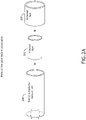
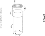
- FIGS. 2A-2B exploded perspective views of a composite rod with tubular shape 200 and metal collars with similar tubular shapes 202, 204 during a fabrication process according to an exemplary embodiment are shown.
- An internal collar 202 is inserted into an end of the composite rod 200 and a corresponding external collar 204 is placed over the end of the composite rod 200 and internal collar 202 such that the end of the composite rod 200 is sandwiched between the internal collar 202 and the external collar 204.
- the internal collar 202 and external collar 204 define a producing portion 206 where the internal collar 202 and external collar 204 extend beyond the end of the composite rod 200.
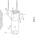
- FIG. 3 a perspective view of a composite rod 300 and metal collars 302, 304 during a fabrication process according to an exemplary embodiment is shown.
- a clamp device 306, 308 is disposed around collars 302, 304, including some portion of the composite rod 300, or at least some terminal portion of the collars 302, 304 and composite rod 300.
- the clamping load is unidirectional compression applied in the radial direction as shown in FIG.3 .
- FIGS. 4A-4B cross-sectional views of a composite rod 400 and metal collars 402, 404 during a fabrication process according to an exemplary embodiment are shown before the clamping.
- a clamp device 406, 408 is disposed around a terminal of the composite rod 400 and collars 402, 404.
- the clamp device 406, 408 defines a deformation profile 410. When sufficient compressive load is applied to the clamp device 406, 408, the terminal of the composite rod 400 and collars 402, 404 are deformed according to the deformation profile 410.
- the deformation profile 410 deforms the terminal of the composite rod 400 and collars 402, 404 progressively more from a proximal portion of a distal portion of the clamp device 406, 408.
- FIGS. 5A-5B cross-sectional view of a composite rod 500 and metal collars 502, 504 during a fabrication process according to an exemplary embodiment are shown after the clamping.
- a compressive force is applied to a clamp device 506, 508, the terminal of the composite rod 500 and collars 502, 504 are plastically deformed to produce one or more interlocking portions 510 where the composite rod 500, internal collar 502, and external collar 504 are engaged to transfer axial compressive and tensile loads, even without friction between the collars and the composite road.
- the clamp device 506, 508 and corresponding deformation profile define a proximal portion that leaves the corresponding portion of the composite rod 500 and collars 502, 504 relatively undeformed. Furthermore, the clamp device 506, 508 and corresponding deformation profile define a distal portion that produces the maximal deformation produced by the clamp device 506, 508, potentially flattening the collars 502, 504. In at least one embodiment, the distal portion may correspond to a portion including only the collars 502, 504, and not the composite rod 500.
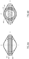
- FIGS. 6A-6B front and rear diametric views of a composite rod 600 and metal collars 602, 604 produced according to an exemplary embodiment are shown.
- a flattened metal tab comprising a deformed internal collar 602 and a deformed external collar 604 protrudes from the composite rod 600 that may be connected to other components.
- a rear view (as in FIG. 6B ) the composite rod 600 retains its shape and therefore structural integrity while protruding from the joint defined by the metal collars 602, 604, with a deformed portion of the composite rod 600 secured within the metal joint.
- FIG. 7 an axial side cross-sectional view of a support element under an axial tensile load and corresponding load transfer between the internal collar and the composite rod end are shown according to an exemplary embodiment.
- a tensile load is applied to the support element via the metal joint, the tensile load is transferred between the composite rod 700 and the internal collar 702 and external collar 704 at regions where the composite rod 700, the internal collar 702, and external collar 704 are deformed to interlock.
- FIG. 8 an axial top cross-sectional view of a support element under an axial compressive load and corresponding load transfer between the external collar and the composite rod end are shown according to an exemplary embodiment.
- a tensile load is applied to the support element via the metal joint, the tensile load is transferred between the composite rod 800 and the internal collar 802 and external collar 804 at regions where the composite rod 800, the internal collar 802, and external collar 804 are deformed to interlock.
- a clamp device 900 may define a curved deformation profile 908 to provide a smooth transition between an undeformed portion of a composite rod and a maximally deformed portion to produce a metal collar.
- a clamp device 902 may define a stepped deformation profile 908 to transition between an undeformed portion of a composite rod and a maximally deformed portion to produce a metal collar.
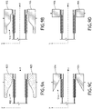
- FIG. 9A axial side cross-sectional views of deformation clamps according to exemplary embodiments are shown.
- a clamp device 900 may define a curved deformation profile 908 to provide a smooth transition between an undeformed portion of a composite rod and a maximally deformed portion to produce a metal collar.
- a clamp device 902 may define a stepped deformation profile 908 to transition between an undeformed portion of a composite rod and a maximally deformed portion to produce a metal collar.
- a clamp device 904 may define a linear sloped deformation profile 908 to transition between an undeformed portion of a composite rod and a maximally deformed portion to produce a metal collar.
- a clamp device 906 may define a block with flat contact surface to deform a terminal portion with the remaining portion of the metal joint deforming according to the properties of the material.
- Other profiles e.g., combing multiple segments with either curved or linear slopped or flat shapes, can be used in other embodiments.
- clamp 900, 902, 904, 906 used for a particular purpose may be defined by the compressive clamping load that will be applied or by the shape of the space where the joint will ultimately be disposed. Certain composite supports may fit a space more easily based on the shape of the joint.
- an axial side cross-sectional view of a joint is shown.
- the metal collars may be joined together.
- an overlapping portion 1000 of metal collars, such as the flattened metal tab portions, may be affixed to each other, for example, via rivets 1006 or bolted through holes 1008.
- deformed internal collars 1002 and deformed external collars 1004 may be configured to interlock with metal joints of other composite rods.
- a deformed internal collar 1002 of one metal joint may protrude from the corresponding deformed external collar 1004 such that the protruding portion may be inserted in a deformed external collar 1004 that protrudes from a deformed internal collar 1002 of a second composite rod.
- FIG. 11 a flowchart of a method for producing a composite support element according to an exemplary embodiment is shown.
- an internal collar is fitted 1102 into a composite rod. It may be preferrable that the internal collar produces complete contact with the composite rod but some minimal gap is acceptable.
- tapering or chamfering the internal collar may facilitate insertion into the composite rod.
- some plastic deformation of the internal collar may be applied in a separate process to direct the deformation of the composite rod in a later compression step.
- An external collar is fitted 1104 around the composite rod corresponding to the location of the internal collar.
- a clamp is applied 1106 to the external collar.
- the clamp may define a deformation profile to guide the deformation of terminal end of the composite rod and collars.
- a compressive force is applied 1108 to the clamp to produce plastic deformation in the composite rod and collars.
- heat may be applied to the collars and composite rod before the compressive force is applied.
- the application of compressive force by itself may produce heat that facilitates plastic deformation.
- post deformation processing may be applied 1110.
- Post deformation processing includes a curing step for the thermoset composite rod. In this case, plastic deformation of the composite rod is performed first for a partially cured material.
- the plastic deformation can include local heating of the area of deformation.
- a post deformation step in this case will include cooling to keep the deformed shape.
- fixation features may be added such as rivet or bolt holes in a formed metal tab.
- Embodiments of the present disclosure provide a simple method of making composite supports off-the-shelf metallic parts. Such composite supports would provide reduced cost, shortened time of fabrication, and reduced weight. Furthermore, such composite supports may be more easily produced via automation for mass production. Also, such embodiments may obviate supply-chain management and international trade issues, etc.
- embodiments of the present disclosure may be useful in any type of composite joining applications, including bicycles, civil engineering, and transportation linkages.
Landscapes
- Engineering & Computer Science (AREA)
- Mechanical Engineering (AREA)
- Chemical & Material Sciences (AREA)
- Composite Materials (AREA)
- Aviation & Aerospace Engineering (AREA)
- Mutual Connection Of Rods And Tubes (AREA)
- General Engineering & Computer Science (AREA)
Abstract
Description
- Composite support structures and frames, such as found in aircraft seats, provide significant weight reduction in comparison with conventional metallic supports and frames. Such systems generally comprise composite rods connected by metallic joints. Composite rods and, especially, composite rods with tubular shapes are relatively inexpensively to fabricate. However, the metallic joints are both heavy and expensive. Even efficient joint designs have complex shapes of monolithic metallic parts requiring considerable, expensive labor. Furthermore, they require significant advance planning with obvious sensitivity to supply chains. It would be advantageous to have a method for joining composite rods in a composite support structure without expensive machining or compromising the structural integrity of the composite rods.
- In one aspect, embodiments of the inventive concepts disclosed herein are directed to a method for joining composite rods with tubular shape without expensive, machined connectors and without compromising the structural integrity of the composite rod. Internal and external collars are applied to the ends of the composite rod and deformed via unidirectional compressive load applied by a clamp in the radial direction of the composite rod cross-section. The resulting plastic deformation of the metal collars and composite rod interlock those components to support both compressive and tensile loads. The deformed metal collars are easily joinable to other components via off-the-shelf hardware.
- In a further aspect, the clamp defines any of a plurality of deformation profiles according to the specific application and available space.
- It is to be understood that both the foregoing general description and the following detailed description are exemplary and explanatory only and should not restrict the scope of the claims. The accompanying drawings, which are incorporated in and constitute a part of the specification, illustrate exemplary embodiments of the inventive concepts disclosed herein and together with the general description, serve to explain the principles.
- The numerous advantages of the embodiments of the inventive concepts disclosed herein may be better understood by those skilled in the art by reference to the accompanying figures in which:
-
FIG. 1 shows an environmental perspective view of a representative aircraft seat frame including composite rods and hybrid composite metal joints; -
FIG. 2A shows an exploded perspective view of a composite rod and metal collars before mutual positioning during a fabrication process according to an exemplary embodiment; -
FIG. 2B shows a perspective view of a composite rod and metal collars after mutual positioning during a fabrication process according to an exemplary embodiment; -
FIG. 3 shows a perspective view of a composite rod and metal collars prepared for clamping during a fabrication process according to an exemplary embodiment; -
FIG. 4A shows an axial cross-sectional view of a composite rod and metal collars prepared for clamping during a fabrication process according to an exemplary embodiment; -
FIG. 4B shows a diametric cross-sectional view of a composite rod and metal collars prepared for clamping during a fabrication process according to an exemplary embodiment; -
FIG. 5A shows an axial cross-sectional view of a composite rod and metal collars after clamping during a fabrication process according to an exemplary embodiment; -
FIG. 5B shows a diametric cross-sectional view of a composite rod and metal collars after clamping during a fabrication process according to an exemplary embodiment; -
FIG. 6A shows a diametric front view of a composite rod and metal collars produced after clamping according to an exemplary embodiment; -
FIG. 6B shows a diametric rear view of a composite rod and metal collars produced after clamping according to an exemplary embodiment; -
FIG. 7 shows an axial side cross-sectional view of a support element under a tensile load and corresponding load transfer between the internal collar and the composite rod end according to an exemplary embodiment; -
FIG. 8 shows an axial top cross-sectional view of a support element under a compressive load and corresponding load transfer between the external collar and the composite rod end according to an exemplary embodiment; -
FIG. 9A shows an axial side cross-sectional view of a deformation clamp with curved shape according to an exemplary embodiment; -
FIG. 9B shows an axial side cross-sectional view of a deformation clamp with shape of multiple linear segments according to an exemplary embodiment; -
FIG. 9C shows an axial side cross-sectional view of a deformation clamp with sloped shape according to an exemplary embodiment; -
FIG. 9D shows an axial side cross-sectional view of a deformation clamp with flat shape according to an exemplary embodiment; -
FIG. 10 shows an axial side cross-sectional view of a joint according to an exemplary embodiment; -
FIG. 11 shows a flowchart of a method for producing a composite support element according to an exemplary embodiment. - Before explaining at least one embodiment of the inventive concepts disclosed herein in detail, it is to be understood that the inventive concepts are not limited in their application to the details of construction and the arrangement of the components or steps or methodologies set forth in the following description or illustrated in the drawings. In the following detailed description of embodiments of the instant inventive concepts, numerous specific details are set forth in order to provide a more thorough understanding of the inventive concepts. However, it will be apparent to one of ordinary skill in the art having the benefit of the instant disclosure that the inventive concepts disclosed herein may be practiced without these specific details. In other instances, well-known features may not be described in detail to avoid unnecessarily complicating the instant disclosure. The inventive concepts disclosed herein are capable of other embodiments or of being practiced or carried out in various ways within the scope of the claims. Also, it is to be understood that the phraseology and terminology employed herein is for the purpose of description and should not be regarded as limiting.
- As used herein a letter following a reference numeral is intended to reference an embodiment of the feature or element that may be similar, but not necessarily identical, to a previously described element or feature bearing the same reference numeral (e.g., 1, 1a, 1b). Such shorthand notations are used for purposes of convenience only, and should not be construed to limit the inventive concepts disclosed herein in any way unless expressly stated to the contrary.
- Further, unless expressly stated to the contrary, "or" refers to an inclusive or and not to an exclusive or. For example, a condition A or B is satisfied by anyone of the following: A is true (or present) and B is false (or not present), A is false (or not present) and B is true (or present), and both A and B are true (or present).
- In addition, use of the "a" or "an" are employed to describe elements and components of embodiments of the instant inventive concepts. This is done merely for convenience and to give a general sense of the inventive concepts, and "a" and "an" are intended to include one or at least one and the singular also includes the plural unless it is obvious that it is meant otherwise.
- Finally, as used herein any reference to "one embodiment," or "some embodiments" means that a particular element, feature, structure, or characteristic described in connection with the embodiment is included in at least one embodiment of the inventive concepts disclosed herein. The appearances of the phrase "in some embodiments" in various places in the specification are not necessarily all referring to the same embodiment, and embodiments of the inventive concepts disclosed may include one or more of the features expressly described or inherently present herein, or any combination of sub-combination of two or more such features, along with any other features which may not necessarily be expressly described or inherently present in the instant disclosure.
- Broadly, embodiments of the inventive concepts disclosed herein are directed to a method for joining composite rods with tubular shape without expensive, machined connectors and without compromising the structural integrity of the composite rod. Internal and external collars are applied to the ends of the composite rod and deformed via unidirectional compressive load applied by a clamp in the radial direction of the composite rod cross-section. The resulting plastic deformation of the metal collars and composite rod interlock those components to support both compressive and tensile loads. The deformed metal collars are easily joinable to other components via off-the-shelf hardware.
- In a further aspect, the clamp defines any of a plurality of deformation profiles according to the specific application and available space.
- Referring to
FIG. 1 , an environmental perspective view of a representative aircraft seat frame includingcomposite rods 100 and hybridcomposite metal joints 102 is shown. Thecomposite rods 100 comprise light weight composite tubes produced via some method such as filament-winding, extrusion, wrapping, advanced filament placing (AFP), braiding, etc. In conventional implementations, themetal joints 102 for securing suchcomposite rods 100 together or to other components of the seat frame are traditionally multi-part, machined components specially adapted for thecomposite rods 100 and specific portion of the seat frame. Thus, they are usually relatively expensive, heavy and can require additional time for placing orders in advance. In some other cases, conventional mechanisms for joining themetal joints 102 to thecomposite rods 100 may compromise structural integrity of thecomposite rods 100 due to drilled holes through thecomposite rods 100 if metallic fasteners (e.g., bolts or rivets) are used. - Composite materials considered in this disclosure are fiber-reinforced polymer matrix materials. The fibers can include, among others, carbon, glass, organic fibers or their combinations. The polymer matrices can include thermoplastic and thermoset polymers. Metallic collars are made of metals or alloys showing plastic deformation at, at least, some levels of applied load.
- Referring to
FIGS. 2A-2B , exploded perspective views of a composite rod withtubular shape 200 and metal collars with similartubular shapes internal collar 202 is inserted into an end of thecomposite rod 200 and a correspondingexternal collar 204 is placed over the end of thecomposite rod 200 andinternal collar 202 such that the end of thecomposite rod 200 is sandwiched between theinternal collar 202 and theexternal collar 204. - In at least one embodiment, the
internal collar 202 andexternal collar 204 define a producingportion 206 where theinternal collar 202 andexternal collar 204 extend beyond the end of thecomposite rod 200. - Referring to
FIG. 3 , a perspective view of acomposite rod 300 andmetal collars internal collar 302 is inserted into thecomposite rod 300 and a correspondingexternal collar 304 is placed over the end of thecomposite rod 300 andinternal collar 302, aclamp device collars composite rod 300, or at least some terminal portion of thecollars composite rod 300. The clamping load is unidirectional compression applied in the radial direction as shown inFIG.3 . - Referring to
FIGS. 4A-4B , cross-sectional views of acomposite rod 400 andmetal collars clamp device composite rod 400 andcollars clamp device deformation profile 410. When sufficient compressive load is applied to theclamp device composite rod 400 andcollars deformation profile 410. - In at least one embodiment, the
deformation profile 410 deforms the terminal of thecomposite rod 400 andcollars clamp device - Referring to
FIGS. 5A-5B , cross-sectional view of acomposite rod 500 andmetal collars clamp device composite rod 500 andcollars portions 510 where thecomposite rod 500,internal collar 502, andexternal collar 504 are engaged to transfer axial compressive and tensile loads, even without friction between the collars and the composite road. - In at least one embodiment, the
clamp device composite rod 500 andcollars clamp device clamp device collars collars composite rod 500. - Referring to
FIGS. 6A-6B , front and rear diametric views of acomposite rod 600 andmetal collars FIG. 6A ), a flattened metal tab comprising a deformedinternal collar 602 and a deformedexternal collar 604 protrudes from thecomposite rod 600 that may be connected to other components. In a rear view (as inFIG. 6B ), thecomposite rod 600 retains its shape and therefore structural integrity while protruding from the joint defined by themetal collars composite rod 600 secured within the metal joint. - Referring to
FIG. 7 , an axial side cross-sectional view of a support element under an axial tensile load and corresponding load transfer between the internal collar and the composite rod end are shown according to an exemplary embodiment. When a tensile load is applied to the support element via the metal joint, the tensile load is transferred between thecomposite rod 700 and theinternal collar 702 andexternal collar 704 at regions where thecomposite rod 700, theinternal collar 702, andexternal collar 704 are deformed to interlock. - Referring to
FIG. 8 , an axial top cross-sectional view of a support element under an axial compressive load and corresponding load transfer between the external collar and the composite rod end are shown according to an exemplary embodiment. When a tensile load is applied to the support element via the metal joint, the tensile load is transferred between thecomposite rod 800 and theinternal collar 802 andexternal collar 804 at regions where thecomposite rod 800, theinternal collar 802, andexternal collar 804 are deformed to interlock. - It may be appreciated that under both axial tensile loads (as in
FIG. 7 ) and axial compressive loads (as inFIG. 8 ), a variable angular cross section of the deformed portion ensures positive contact between all surfaces of thecomposite rod internal collar external collar - Referring to
FIGS. 9A-9D , axial side cross-sectional views of deformation clamps according to exemplary embodiments are shown. In at least one embodiment (as inFIG. 9A ), aclamp device 900 may define acurved deformation profile 908 to provide a smooth transition between an undeformed portion of a composite rod and a maximally deformed portion to produce a metal collar. In at least one embodiment (as inFIG. 9B ), aclamp device 902 may define a steppeddeformation profile 908 to transition between an undeformed portion of a composite rod and a maximally deformed portion to produce a metal collar. In at least one embodiment (as inFIG. 9C ), aclamp device 904 may define a linearsloped deformation profile 908 to transition between an undeformed portion of a composite rod and a maximally deformed portion to produce a metal collar. In at least one embodiment (as inFIG. 9D ), aclamp device 906 may define a block with flat contact surface to deform a terminal portion with the remaining portion of the metal joint deforming according to the properties of the material. Other profiles, e.g., combing multiple segments with either curved or linear slopped or flat shapes, can be used in other embodiments. - It may be appreciated that the type of
clamp - Referring to
FIG. 10 , an axial side cross-sectional view of a joint according to an exemplary embodiment is shown. Once composite rods are jointed to deformed metal collars, the metal collars may be joined together. In at least one embodiment, an overlappingportion 1000 of metal collars, such as the flattened metal tab portions, may be affixed to each other, for example, viarivets 1006 or bolted throughholes 1008. - In at least one embodiment, deformed
internal collars 1002 and deformedexternal collars 1004 may be configured to interlock with metal joints of other composite rods. For example, a deformedinternal collar 1002 of one metal joint may protrude from the corresponding deformedexternal collar 1004 such that the protruding portion may be inserted in a deformedexternal collar 1004 that protrudes from a deformedinternal collar 1002 of a second composite rod. - Referring to
FIG. 11 , a flowchart of a method for producing a composite support element according to an exemplary embodiment is shown. During a production process, an internal collar is fitted 1102 into a composite rod. It may be preferrable that the internal collar produces complete contact with the composite rod but some minimal gap is acceptable. In at least one embodiment, tapering or chamfering the internal collar may facilitate insertion into the composite rod. In at least one embodiment, some plastic deformation of the internal collar may be applied in a separate process to direct the deformation of the composite rod in a later compression step. - An external collar is fitted 1104 around the composite rod corresponding to the location of the internal collar. A clamp is applied 1106 to the external collar. The clamp may define a deformation profile to guide the deformation of terminal end of the composite rod and collars.
- A compressive force is applied 1108 to the clamp to produce plastic deformation in the composite rod and collars. In at least one embodiment, heat may be applied to the collars and composite rod before the compressive force is applied. In at least one embodiment, the application of compressive force by itself may produce heat that facilitates plastic deformation.
- In at least one embodiment, post deformation processing may be applied 1110. Post deformation processing includes a curing step for the thermoset composite rod. In this case, plastic deformation of the composite rod is performed first for a partially cured material.
- If a thermoplastic composite rod is used, the plastic deformation can include local heating of the area of deformation. A post deformation step in this case will include cooling to keep the deformed shape.
- After the joint is formed via deformation and any post processing steps are applied, fixation features may be added such as rivet or bolt holes in a formed metal tab.
- It may be appreciated that while embodiments described herein are directed to producing a flat metal tab, other embodiment produced via clamping are envisioned, including various types of radial compression.
- Embodiments of the present disclosure provide a simple method of making composite supports off-the-shelf metallic parts. Such composite supports would provide reduced cost, shortened time of fabrication, and reduced weight. Furthermore, such composite supports may be more easily produced via automation for mass production. Also, such embodiments may obviate supply-chain management and international trade issues, etc.
- While aircraft seats where specifically mentioned, embodiments of the present disclosure may be useful in any type of composite joining applications, including bicycles, civil engineering, and transportation linkages.
- It is believed that the inventive concepts disclosed herein and many of their attendant advantages will be understood by the foregoing description of embodiments of the inventive concepts disclosed, and it will be apparent that various changes may be made in the form, construction, and arrangement of the components thereof without departing from the scope of the invention as defined by the claims.
Claims (14)
- A method for securing joint components to a composite rod comprising:inserting an internal collar (202) into an end of the composite rod (200);placing an external collar (304) over the end of the composite rod;placing a clamp device (306, 308) around the end of the composite rode over the external collar; anddeforming the internal collar, the external collar, and the end of the composite rod via applying unidirectional compressive load in the radial direction to the clamp device.
- The method of Claim 1, further comprising:heating the end of the composite rod to a predetermined deformation temperature before deformation; andcooling the end of the composite rod after deformation,wherein the composite rod comprises a thermoplastic composite.
- The method of Claim 1, further comprising:partially curing the end of the composite rod before deformation; andcuring the end of the composite rod after deformation.
- The method of any preceding Claim, further comprising machining a deformed portion of the external collar (304) and internal collar (202) to facilitate interconnection to external parts or structures.
- The method of any preceding Claim, wherein the clamping device (306, 308) defines a deformation profile (410) on surfaces proximal to the external collar having a deformation profile.
- The method of Claim 4, wherein the deformation profile defines a stepped profile (908).
- The method of Claim 4, wherein the deformation profile defines a constant radius curve.
- The method of any preceding Claim, further comprising:inserting a second internal collar into an end of a second composite rod;placing the external collar over the end of the second composite rod;placing the clamp device around the end of the second composite rode over the external collar; anddeforming the second internal collar, the external collar, and the end of the second composite rod via applying unidirectional compressive load in the radial direction to the clamp device,wherein the external collar is configured to receive the composite rod in a first end and the second composite rod in a second end.
- A composite support element produced via the method of any preceding claim.
- A support structure comprising:
a plurality of composite support elements, each composite support element comprising:a composite rod (200); andat least one metal joint (102) disposed on an end of the composite rod, the metal joint comprising an internal collar (202) inserted in the end of the composite rod and an external collar (304) over the end of the composite rod,wherein:
the external collar, the end of the composite rod, and the internal collar are deformed to interlock. - The support structure of Claim 10, wherein the deformation comprises a sloped portion.
- The support structure of Claim 10, wherein a first composite support element is affixed to a second composite support element via one or more connectors connecting a deformed portion of the internal collar and external collar of the first support element to the internal collar and external collar of the second support element.
- The support structure of Claim 12, wherein:the internal collar of the first composite support element protrudes beyond the external collar of the first composite support element;the external collar of the second composite support element protrudes beyond the internal collar of the second composite support element; andthe protruding portion of the internal collar of the first composite support element is configured for insertion into the protruding portion of the external collar of the second composite support element.
- The support structure of Claim 10 to 13, wherein the external collar comprises a curved portion and is configured to receive a second composite rod in the plurality of composite support elements in a second open end.
Applications Claiming Priority (1)
| Application Number | Priority Date | Filing Date | Title |
|---|---|---|---|
| US17/167,659 US12036749B2 (en) | 2021-02-04 | 2021-02-04 | Metal composite joints for composite rods |
Publications (2)
| Publication Number | Publication Date |
|---|---|
| EP4039451A1 true EP4039451A1 (en) | 2022-08-10 |
| EP4039451B1 EP4039451B1 (en) | 2024-08-21 |
Family
ID=80218622
Family Applications (1)
| Application Number | Title | Priority Date | Filing Date |
|---|---|---|---|
| EP22155261.5A Active EP4039451B1 (en) | 2021-02-04 | 2022-02-04 | Metal composite joints for composite rods |
Country Status (2)
| Country | Link |
|---|---|
| US (2) | US12036749B2 (en) |
| EP (1) | EP4039451B1 (en) |
Families Citing this family (2)
| Publication number | Priority date | Publication date | Assignee | Title |
|---|---|---|---|---|
| US20250250011A1 (en) * | 2024-02-01 | 2025-08-07 | B/E Aerospace, Inc. | Composite beam joint for aircraft seat frame |
| US20250251003A1 (en) * | 2024-02-01 | 2025-08-07 | B/E Aerospace, Inc. | Joint for composite tubular rods |
Citations (4)
| Publication number | Priority date | Publication date | Assignee | Title |
|---|---|---|---|---|
| US7874925B2 (en) * | 2006-01-17 | 2011-01-25 | Crompton Technology Group Ltd. | Transmission shaft joint design |
| DE102013019097A1 (en) * | 2012-11-12 | 2014-05-15 | Volker Piwek | Joining hollow tubular components, semi-finished products or components with metallic components, comprises e.g. designing metallic components such that it undergoes expansion within tube during joining |
| WO2016009208A1 (en) * | 2014-07-15 | 2016-01-21 | Sigma Precision Components Uk Limited | End fittings for fibre reinforced polymer matrix composite pipes |
| WO2019225294A1 (en) * | 2018-05-23 | 2019-11-28 | 三菱電機株式会社 | Pipe structure and truss structure, and artificial satellite using such structures |
Family Cites Families (12)
| Publication number | Priority date | Publication date | Assignee | Title |
|---|---|---|---|---|
| US4006524A (en) * | 1974-06-12 | 1977-02-08 | The Weatherhead Company | Method of making a hose coupling |
| NO148060C (en) | 1979-06-06 | 1983-08-03 | Johnson Matthey Co Ltd | METHOD AND APPARATUS FOR MANUFACTURE OF PIPE-TUBED COUPLES OF DUKTIL METAL |
| US4715739A (en) * | 1981-02-18 | 1987-12-29 | Ciba-Geigy Corporation | Connection between a plastics quill shaft and a metal element |
| DE4012504C1 (en) | 1990-04-12 | 1991-08-14 | Mannesmann Ag, 4000 Duesseldorf, De | |
| DE4143528C2 (en) * | 1990-10-23 | 1996-08-29 | Gkn Glaenzer Spicer | Union of FRP tube and inner metal tool |
| DE9016310U1 (en) * | 1990-11-30 | 1991-02-21 | Hewing GmbH, 4434 Ochtrup | Pipe connection, especially on composite pipes |
| DE9103264U1 (en) | 1991-03-18 | 1991-06-20 | Hewing GmbH, 4434 Ochtrup | Pressing pliers for pressing pipe connections |
| US7520042B2 (en) * | 2003-10-20 | 2009-04-21 | Flex-Ing, Inc. | Flexible connectors and methods of manufacturing same |
| US7946629B2 (en) * | 2005-10-07 | 2011-05-24 | Flexpipe Systems Inc. | Pipe coupling and method for installation |
| US20090239095A1 (en) | 2008-03-23 | 2009-09-24 | Elmet Technologies, Inc. | Composite rods and processes for forming composite rods |
| DE102008038276B4 (en) | 2008-08-18 | 2018-02-15 | Benteler Automobiltechnik Gmbh | Method for connecting chassis parts and chassis assembly |
| DE102012105655A1 (en) | 2012-06-28 | 2014-01-02 | Viega Gmbh & Co. Kg | Press jaw and method for producing a permanent pipe connection and system of a pressing jaw and a fitting |
-
2021
- 2021-02-04 US US17/167,659 patent/US12036749B2/en active Active
-
2022
- 2022-02-04 EP EP22155261.5A patent/EP4039451B1/en active Active
-
2024
- 2024-06-11 US US18/739,909 patent/US20240326350A1/en active Pending
Patent Citations (4)
| Publication number | Priority date | Publication date | Assignee | Title |
|---|---|---|---|---|
| US7874925B2 (en) * | 2006-01-17 | 2011-01-25 | Crompton Technology Group Ltd. | Transmission shaft joint design |
| DE102013019097A1 (en) * | 2012-11-12 | 2014-05-15 | Volker Piwek | Joining hollow tubular components, semi-finished products or components with metallic components, comprises e.g. designing metallic components such that it undergoes expansion within tube during joining |
| WO2016009208A1 (en) * | 2014-07-15 | 2016-01-21 | Sigma Precision Components Uk Limited | End fittings for fibre reinforced polymer matrix composite pipes |
| WO2019225294A1 (en) * | 2018-05-23 | 2019-11-28 | 三菱電機株式会社 | Pipe structure and truss structure, and artificial satellite using such structures |
Also Published As
| Publication number | Publication date |
|---|---|
| US20220243750A1 (en) | 2022-08-04 |
| US20240326350A1 (en) | 2024-10-03 |
| US12036749B2 (en) | 2024-07-16 |
| EP4039451B1 (en) | 2024-08-21 |
Similar Documents
| Publication | Publication Date | Title |
|---|---|---|
| US20240326350A1 (en) | Metal composite joints for composite rods | |
| DE69711820T2 (en) | Self-lubricating rivets | |
| EP2242682B1 (en) | Method of connecting two fuselage sections with the formation of a transverse joint, and transverse joint connection | |
| US8739492B2 (en) | Space frame connector | |
| KR100199537B1 (en) | Joint unit for hollow profiles | |
| US7044458B2 (en) | Stabilizer bar | |
| US10704637B2 (en) | Bar pin bushing for vehicle suspension | |
| KR101857172B1 (en) | Hybrid suspension arm for vehicle and manufacturing method thereof | |
| EP3174777B1 (en) | Connection arrangement between a fibre-plastic composite profiled part and a vehicle body frame part and method for producing same | |
| US20180100538A1 (en) | Fibre Reinforced Polymer Matrix Composite Torque Tubes or Shafts | |
| EP3638571B1 (en) | Vehicle body module connecting joint | |
| US5217555A (en) | Process for making hollow tubular structural members with integral end attachment fittings | |
| EP3079975B1 (en) | Support structure with a framework design, and method for producing same | |
| DE102016008773A1 (en) | ball joint | |
| CA2586343C (en) | Retrogression heat treatment | |
| CN105538693A (en) | Reinforced moldable rivet assembly for a vehicle | |
| CN1252019A (en) | Methods of joining metal parts | |
| US10974462B2 (en) | Fastener and method for joining dissimilar materials | |
| US20220355409A1 (en) | Hollow welding pin for assembling two different materials. | |
| KR102605914B1 (en) | Joining method of panel | |
| DE102018131052B4 (en) | Method for producing a component composite and motor vehicle | |
| US20230366421A1 (en) | Joints of composite frames for optics support structure | |
| DE102013019097A1 (en) | Joining hollow tubular components, semi-finished products or components with metallic components, comprises e.g. designing metallic components such that it undergoes expansion within tube during joining | |
| US20190242115A1 (en) | Coupling structure for fiber reinforced plastic structure member and machining method for coupling portion | |
| EP2524795A2 (en) | Joining arrangement for two boxes of composite material with an intermediate part and method for producing said intermediate part |
Legal Events
| Date | Code | Title | Description |
|---|---|---|---|
| PUAI | Public reference made under article 153(3) epc to a published international application that has entered the european phase |
Free format text: ORIGINAL CODE: 0009012 |
|
| STAA | Information on the status of an ep patent application or granted ep patent |
Free format text: STATUS: THE APPLICATION HAS BEEN PUBLISHED |
|
| AK | Designated contracting states |
Kind code of ref document: A1 Designated state(s): AL AT BE BG CH CY CZ DE DK EE ES FI FR GB GR HR HU IE IS IT LI LT LU LV MC MK MT NL NO PL PT RO RS SE SI SK SM TR |
|
| STAA | Information on the status of an ep patent application or granted ep patent |
Free format text: STATUS: REQUEST FOR EXAMINATION WAS MADE |
|
| 17P | Request for examination filed |
Effective date: 20230209 |
|
| RBV | Designated contracting states (corrected) |
Designated state(s): AL AT BE BG CH CY CZ DE DK EE ES FI FR GB GR HR HU IE IS IT LI LT LU LV MC MK MT NL NO PL PT RO RS SE SI SK SM TR |
|
| P01 | Opt-out of the competence of the unified patent court (upc) registered |
Effective date: 20230922 |
|
| RIC1 | Information provided on ipc code assigned before grant |
Ipc: B29C 70/30 20060101ALN20240117BHEP Ipc: B29L 31/00 20060101ALN20240117BHEP Ipc: B29L 31/24 20060101ALN20240117BHEP Ipc: B29C 70/54 20060101ALI20240117BHEP Ipc: F16L 13/14 20060101ALI20240117BHEP Ipc: B29C 70/46 20060101ALI20240117BHEP Ipc: B29C 57/10 20060101ALI20240117BHEP Ipc: B64D 11/06 20060101ALI20240117BHEP Ipc: B29C 65/64 20060101ALI20240117BHEP Ipc: B29C 65/56 20060101ALI20240117BHEP Ipc: B29C 65/00 20060101AFI20240117BHEP |
|
| RIC1 | Information provided on ipc code assigned before grant |
Ipc: B29C 70/30 20060101ALN20240131BHEP Ipc: B29L 31/00 20060101ALN20240131BHEP Ipc: B29L 31/24 20060101ALN20240131BHEP Ipc: B29C 70/54 20060101ALI20240131BHEP Ipc: F16L 13/14 20060101ALI20240131BHEP Ipc: B29C 70/46 20060101ALI20240131BHEP Ipc: B29C 57/10 20060101ALI20240131BHEP Ipc: B64D 11/06 20060101ALI20240131BHEP Ipc: B29C 65/64 20060101ALI20240131BHEP Ipc: B29C 65/56 20060101ALI20240131BHEP Ipc: B29C 65/00 20060101AFI20240131BHEP |
|
| GRAP | Despatch of communication of intention to grant a patent |
Free format text: ORIGINAL CODE: EPIDOSNIGR1 |
|
| STAA | Information on the status of an ep patent application or granted ep patent |
Free format text: STATUS: GRANT OF PATENT IS INTENDED |
|
| INTG | Intention to grant announced |
Effective date: 20240315 |
|
| GRAS | Grant fee paid |
Free format text: ORIGINAL CODE: EPIDOSNIGR3 |
|
| GRAA | (expected) grant |
Free format text: ORIGINAL CODE: 0009210 |
|
| STAA | Information on the status of an ep patent application or granted ep patent |
Free format text: STATUS: THE PATENT HAS BEEN GRANTED |
|
| AK | Designated contracting states |
Kind code of ref document: B1 Designated state(s): AL AT BE BG CH CY CZ DE DK EE ES FI FR GB GR HR HU IE IS IT LI LT LU LV MC MK MT NL NO PL PT RO RS SE SI SK SM TR |
|
| REG | Reference to a national code |
Ref country code: GB Ref legal event code: FG4D |
|
| REG | Reference to a national code |
Ref country code: CH Ref legal event code: EP |
|
| REG | Reference to a national code |
Ref country code: IE Ref legal event code: FG4D |
|
| REG | Reference to a national code |
Ref country code: DE Ref legal event code: R096 Ref document number: 602022005386 Country of ref document: DE |
|
| REG | Reference to a national code |
Ref country code: LT Ref legal event code: MG9D |
|
| REG | Reference to a national code |
Ref country code: NL Ref legal event code: MP Effective date: 20240821 |
|
| PG25 | Lapsed in a contracting state [announced via postgrant information from national office to epo] |
Ref country code: NO Free format text: LAPSE BECAUSE OF FAILURE TO SUBMIT A TRANSLATION OF THE DESCRIPTION OR TO PAY THE FEE WITHIN THE PRESCRIBED TIME-LIMIT Effective date: 20241121 |
|
| REG | Reference to a national code |
Ref country code: AT Ref legal event code: MK05 Ref document number: 1715144 Country of ref document: AT Kind code of ref document: T Effective date: 20240821 |
|
| PG25 | Lapsed in a contracting state [announced via postgrant information from national office to epo] |
Ref country code: PT Free format text: LAPSE BECAUSE OF FAILURE TO SUBMIT A TRANSLATION OF THE DESCRIPTION OR TO PAY THE FEE WITHIN THE PRESCRIBED TIME-LIMIT Effective date: 20241223 Ref country code: NL Free format text: LAPSE BECAUSE OF FAILURE TO SUBMIT A TRANSLATION OF THE DESCRIPTION OR TO PAY THE FEE WITHIN THE PRESCRIBED TIME-LIMIT Effective date: 20240821 Ref country code: GR Free format text: LAPSE BECAUSE OF FAILURE TO SUBMIT A TRANSLATION OF THE DESCRIPTION OR TO PAY THE FEE WITHIN THE PRESCRIBED TIME-LIMIT Effective date: 20241122 Ref country code: FI Free format text: LAPSE BECAUSE OF FAILURE TO SUBMIT A TRANSLATION OF THE DESCRIPTION OR TO PAY THE FEE WITHIN THE PRESCRIBED TIME-LIMIT Effective date: 20240821 Ref country code: PL Free format text: LAPSE BECAUSE OF FAILURE TO SUBMIT A TRANSLATION OF THE DESCRIPTION OR TO PAY THE FEE WITHIN THE PRESCRIBED TIME-LIMIT Effective date: 20240821 |
|
| PG25 | Lapsed in a contracting state [announced via postgrant information from national office to epo] |
Ref country code: BG Free format text: LAPSE BECAUSE OF FAILURE TO SUBMIT A TRANSLATION OF THE DESCRIPTION OR TO PAY THE FEE WITHIN THE PRESCRIBED TIME-LIMIT Effective date: 20240821 |
|
| PG25 | Lapsed in a contracting state [announced via postgrant information from national office to epo] |
Ref country code: LV Free format text: LAPSE BECAUSE OF FAILURE TO SUBMIT A TRANSLATION OF THE DESCRIPTION OR TO PAY THE FEE WITHIN THE PRESCRIBED TIME-LIMIT Effective date: 20240821 |
|
| PG25 | Lapsed in a contracting state [announced via postgrant information from national office to epo] |
Ref country code: AT Free format text: LAPSE BECAUSE OF FAILURE TO SUBMIT A TRANSLATION OF THE DESCRIPTION OR TO PAY THE FEE WITHIN THE PRESCRIBED TIME-LIMIT Effective date: 20240821 Ref country code: IS Free format text: LAPSE BECAUSE OF FAILURE TO SUBMIT A TRANSLATION OF THE DESCRIPTION OR TO PAY THE FEE WITHIN THE PRESCRIBED TIME-LIMIT Effective date: 20241221 |
|
| PG25 | Lapsed in a contracting state [announced via postgrant information from national office to epo] |
Ref country code: HR Free format text: LAPSE BECAUSE OF FAILURE TO SUBMIT A TRANSLATION OF THE DESCRIPTION OR TO PAY THE FEE WITHIN THE PRESCRIBED TIME-LIMIT Effective date: 20240821 |
|
| PG25 | Lapsed in a contracting state [announced via postgrant information from national office to epo] |
Ref country code: ES Free format text: LAPSE BECAUSE OF FAILURE TO SUBMIT A TRANSLATION OF THE DESCRIPTION OR TO PAY THE FEE WITHIN THE PRESCRIBED TIME-LIMIT Effective date: 20240821 Ref country code: RS Free format text: LAPSE BECAUSE OF FAILURE TO SUBMIT A TRANSLATION OF THE DESCRIPTION OR TO PAY THE FEE WITHIN THE PRESCRIBED TIME-LIMIT Effective date: 20241121 |
|
| PG25 | Lapsed in a contracting state [announced via postgrant information from national office to epo] |
Ref country code: RS Free format text: LAPSE BECAUSE OF FAILURE TO SUBMIT A TRANSLATION OF THE DESCRIPTION OR TO PAY THE FEE WITHIN THE PRESCRIBED TIME-LIMIT Effective date: 20241121 Ref country code: PT Free format text: LAPSE BECAUSE OF FAILURE TO SUBMIT A TRANSLATION OF THE DESCRIPTION OR TO PAY THE FEE WITHIN THE PRESCRIBED TIME-LIMIT Effective date: 20241223 Ref country code: PL Free format text: LAPSE BECAUSE OF FAILURE TO SUBMIT A TRANSLATION OF THE DESCRIPTION OR TO PAY THE FEE WITHIN THE PRESCRIBED TIME-LIMIT Effective date: 20240821 Ref country code: NO Free format text: LAPSE BECAUSE OF FAILURE TO SUBMIT A TRANSLATION OF THE DESCRIPTION OR TO PAY THE FEE WITHIN THE PRESCRIBED TIME-LIMIT Effective date: 20241121 Ref country code: NL Free format text: LAPSE BECAUSE OF FAILURE TO SUBMIT A TRANSLATION OF THE DESCRIPTION OR TO PAY THE FEE WITHIN THE PRESCRIBED TIME-LIMIT Effective date: 20240821 Ref country code: LV Free format text: LAPSE BECAUSE OF FAILURE TO SUBMIT A TRANSLATION OF THE DESCRIPTION OR TO PAY THE FEE WITHIN THE PRESCRIBED TIME-LIMIT Effective date: 20240821 Ref country code: IS Free format text: LAPSE BECAUSE OF FAILURE TO SUBMIT A TRANSLATION OF THE DESCRIPTION OR TO PAY THE FEE WITHIN THE PRESCRIBED TIME-LIMIT Effective date: 20241221 Ref country code: HR Free format text: LAPSE BECAUSE OF FAILURE TO SUBMIT A TRANSLATION OF THE DESCRIPTION OR TO PAY THE FEE WITHIN THE PRESCRIBED TIME-LIMIT Effective date: 20240821 Ref country code: GR Free format text: LAPSE BECAUSE OF FAILURE TO SUBMIT A TRANSLATION OF THE DESCRIPTION OR TO PAY THE FEE WITHIN THE PRESCRIBED TIME-LIMIT Effective date: 20241122 Ref country code: FI Free format text: LAPSE BECAUSE OF FAILURE TO SUBMIT A TRANSLATION OF THE DESCRIPTION OR TO PAY THE FEE WITHIN THE PRESCRIBED TIME-LIMIT Effective date: 20240821 Ref country code: ES Free format text: LAPSE BECAUSE OF FAILURE TO SUBMIT A TRANSLATION OF THE DESCRIPTION OR TO PAY THE FEE WITHIN THE PRESCRIBED TIME-LIMIT Effective date: 20240821 Ref country code: BG Free format text: LAPSE BECAUSE OF FAILURE TO SUBMIT A TRANSLATION OF THE DESCRIPTION OR TO PAY THE FEE WITHIN THE PRESCRIBED TIME-LIMIT Effective date: 20240821 Ref country code: AT Free format text: LAPSE BECAUSE OF FAILURE TO SUBMIT A TRANSLATION OF THE DESCRIPTION OR TO PAY THE FEE WITHIN THE PRESCRIBED TIME-LIMIT Effective date: 20240821 |
|
| PG25 | Lapsed in a contracting state [announced via postgrant information from national office to epo] |
Ref country code: RO Free format text: LAPSE BECAUSE OF FAILURE TO SUBMIT A TRANSLATION OF THE DESCRIPTION OR TO PAY THE FEE WITHIN THE PRESCRIBED TIME-LIMIT Effective date: 20240821 Ref country code: SM Free format text: LAPSE BECAUSE OF FAILURE TO SUBMIT A TRANSLATION OF THE DESCRIPTION OR TO PAY THE FEE WITHIN THE PRESCRIBED TIME-LIMIT Effective date: 20240821 Ref country code: DK Free format text: LAPSE BECAUSE OF FAILURE TO SUBMIT A TRANSLATION OF THE DESCRIPTION OR TO PAY THE FEE WITHIN THE PRESCRIBED TIME-LIMIT Effective date: 20240821 |
|
| PG25 | Lapsed in a contracting state [announced via postgrant information from national office to epo] |
Ref country code: EE Free format text: LAPSE BECAUSE OF FAILURE TO SUBMIT A TRANSLATION OF THE DESCRIPTION OR TO PAY THE FEE WITHIN THE PRESCRIBED TIME-LIMIT Effective date: 20240821 |
|
| PG25 | Lapsed in a contracting state [announced via postgrant information from national office to epo] |
Ref country code: CZ Free format text: LAPSE BECAUSE OF FAILURE TO SUBMIT A TRANSLATION OF THE DESCRIPTION OR TO PAY THE FEE WITHIN THE PRESCRIBED TIME-LIMIT Effective date: 20240821 |
|
| PG25 | Lapsed in a contracting state [announced via postgrant information from national office to epo] |
Ref country code: SK Free format text: LAPSE BECAUSE OF FAILURE TO SUBMIT A TRANSLATION OF THE DESCRIPTION OR TO PAY THE FEE WITHIN THE PRESCRIBED TIME-LIMIT Effective date: 20240821 Ref country code: IT Free format text: LAPSE BECAUSE OF FAILURE TO SUBMIT A TRANSLATION OF THE DESCRIPTION OR TO PAY THE FEE WITHIN THE PRESCRIBED TIME-LIMIT Effective date: 20240821 |
|
| REG | Reference to a national code |
Ref country code: DE Ref legal event code: R097 Ref document number: 602022005386 Country of ref document: DE |
|
| PLBE | No opposition filed within time limit |
Free format text: ORIGINAL CODE: 0009261 |
|
| STAA | Information on the status of an ep patent application or granted ep patent |
Free format text: STATUS: NO OPPOSITION FILED WITHIN TIME LIMIT |
|
| 26N | No opposition filed |
Effective date: 20250522 |
|
| PG25 | Lapsed in a contracting state [announced via postgrant information from national office to epo] |
Ref country code: SE Free format text: LAPSE BECAUSE OF FAILURE TO SUBMIT A TRANSLATION OF THE DESCRIPTION OR TO PAY THE FEE WITHIN THE PRESCRIBED TIME-LIMIT Effective date: 20240821 |
|
| PG25 | Lapsed in a contracting state [announced via postgrant information from national office to epo] |
Ref country code: MC Free format text: LAPSE BECAUSE OF FAILURE TO SUBMIT A TRANSLATION OF THE DESCRIPTION OR TO PAY THE FEE WITHIN THE PRESCRIBED TIME-LIMIT Effective date: 20240821 |
|
| REG | Reference to a national code |
Ref country code: CH Ref legal event code: PL |
|
| PG25 | Lapsed in a contracting state [announced via postgrant information from national office to epo] |
Ref country code: LU Free format text: LAPSE BECAUSE OF NON-PAYMENT OF DUE FEES Effective date: 20250204 |
|
| PG25 | Lapsed in a contracting state [announced via postgrant information from national office to epo] |
Ref country code: CH Free format text: LAPSE BECAUSE OF NON-PAYMENT OF DUE FEES Effective date: 20250228 |
|
| REG | Reference to a national code |
Ref country code: BE Ref legal event code: MM Effective date: 20250228 |
|
| PG25 | Lapsed in a contracting state [announced via postgrant information from national office to epo] |
Ref country code: BE Free format text: LAPSE BECAUSE OF NON-PAYMENT OF DUE FEES Effective date: 20250228 |
|
| PG25 | Lapsed in a contracting state [announced via postgrant information from national office to epo] |
Ref country code: IE Free format text: LAPSE BECAUSE OF NON-PAYMENT OF DUE FEES Effective date: 20250204 |
|
| PGFP | Annual fee paid to national office [announced via postgrant information from national office to epo] |
Ref country code: GB Payment date: 20260122 Year of fee payment: 5 |
|
| PGFP | Annual fee paid to national office [announced via postgrant information from national office to epo] |
Ref country code: DE Payment date: 20260121 Year of fee payment: 5 |
|
| PGFP | Annual fee paid to national office [announced via postgrant information from national office to epo] |
Ref country code: FR Payment date: 20260121 Year of fee payment: 5 |