EP4039415B1 - Electric power tool and battery pack - Google Patents
Electric power tool and battery pack Download PDFInfo
- Publication number
- EP4039415B1 EP4039415B1 EP20870845.3A EP20870845A EP4039415B1 EP 4039415 B1 EP4039415 B1 EP 4039415B1 EP 20870845 A EP20870845 A EP 20870845A EP 4039415 B1 EP4039415 B1 EP 4039415B1
- Authority
- EP
- European Patent Office
- Prior art keywords
- battery pack
- tool
- electric tool
- battery
- grip portion
- Prior art date
- Legal status (The legal status is an assumption and is not a legal conclusion. Google has not performed a legal analysis and makes no representation as to the accuracy of the status listed.)
- Active
Links
Images


Classifications
-
- B—PERFORMING OPERATIONS; TRANSPORTING
- B25—HAND TOOLS; PORTABLE POWER-DRIVEN TOOLS; MANIPULATORS
- B25F—COMBINATION OR MULTI-PURPOSE TOOLS NOT OTHERWISE PROVIDED FOR; DETAILS OR COMPONENTS OF PORTABLE POWER-DRIVEN TOOLS NOT PARTICULARLY RELATED TO THE OPERATIONS PERFORMED AND NOT OTHERWISE PROVIDED FOR
- B25F5/00—Details or components of portable power-driven tools not particularly related to the operations performed and not otherwise provided for
- B25F5/02—Construction of casings, bodies or handles
-
- H—ELECTRICITY
- H01—ELECTRIC ELEMENTS
- H01M—PROCESSES OR MEANS, e.g. BATTERIES, FOR THE DIRECT CONVERSION OF CHEMICAL ENERGY INTO ELECTRICAL ENERGY
- H01M10/00—Secondary cells; Manufacture thereof
- H01M10/05—Accumulators with non-aqueous electrolyte
-
- H—ELECTRICITY
- H01—ELECTRIC ELEMENTS
- H01M—PROCESSES OR MEANS, e.g. BATTERIES, FOR THE DIRECT CONVERSION OF CHEMICAL ENERGY INTO ELECTRICAL ENERGY
- H01M50/00—Constructional details or processes of manufacture of the non-active parts of electrochemical cells other than fuel cells, e.g. hybrid cells
- H01M50/20—Mountings; Secondary casings or frames; Racks, modules or packs; Suspension devices; Shock absorbers; Transport or carrying devices; Holders
- H01M50/204—Racks, modules or packs for multiple batteries or multiple cells
- H01M50/207—Racks, modules or packs for multiple batteries or multiple cells characterised by their shape
- H01M50/209—Racks, modules or packs for multiple batteries or multiple cells characterised by their shape adapted for prismatic or rectangular cells
-
- H—ELECTRICITY
- H01—ELECTRIC ELEMENTS
- H01M—PROCESSES OR MEANS, e.g. BATTERIES, FOR THE DIRECT CONVERSION OF CHEMICAL ENERGY INTO ELECTRICAL ENERGY
- H01M50/00—Constructional details or processes of manufacture of the non-active parts of electrochemical cells other than fuel cells, e.g. hybrid cells
- H01M50/20—Mountings; Secondary casings or frames; Racks, modules or packs; Suspension devices; Shock absorbers; Transport or carrying devices; Holders
- H01M50/247—Mountings; Secondary casings or frames; Racks, modules or packs; Suspension devices; Shock absorbers; Transport or carrying devices; Holders specially adapted for portable devices, e.g. mobile phones, computers, hand tools or pacemakers
-
- H—ELECTRICITY
- H01—ELECTRIC ELEMENTS
- H01M—PROCESSES OR MEANS, e.g. BATTERIES, FOR THE DIRECT CONVERSION OF CHEMICAL ENERGY INTO ELECTRICAL ENERGY
- H01M50/00—Constructional details or processes of manufacture of the non-active parts of electrochemical cells other than fuel cells, e.g. hybrid cells
- H01M50/20—Mountings; Secondary casings or frames; Racks, modules or packs; Suspension devices; Shock absorbers; Transport or carrying devices; Holders
- H01M50/256—Carrying devices, e.g. belts
-
- H—ELECTRICITY
- H02—GENERATION; CONVERSION OR DISTRIBUTION OF ELECTRIC POWER
- H02J—ELECTRIC POWER NETWORKS; CIRCUIT ARRANGEMENTS OR SYSTEMS FOR SUPPLYING OR DISTRIBUTING ELECTRIC POWER; SYSTEMS FOR STORING ELECTRIC ENERGY
- H02J7/00—Circuit arrangements for charging or discharging batteries or for supplying loads from batteries
- H02J7/70—Circuit arrangements for charging or discharging batteries or for supplying loads from batteries characterised by the mechanical construction
- H02J7/751—Circuit arrangements for charging or discharging batteries or for supplying loads from batteries characterised by the mechanical construction concerning the insertion or the connection of the batteries
-
- H—ELECTRICITY
- H02—GENERATION; CONVERSION OR DISTRIBUTION OF ELECTRIC POWER
- H02J—ELECTRIC POWER NETWORKS; CIRCUIT ARRANGEMENTS OR SYSTEMS FOR SUPPLYING OR DISTRIBUTING ELECTRIC POWER; SYSTEMS FOR STORING ELECTRIC ENERGY
- H02J7/00—Circuit arrangements for charging or discharging batteries or for supplying loads from batteries
- H02J7/855—Circuit arrangements for charging or discharging batteries or for supplying loads from batteries with circuits adapted for supplying loads from the battery
-
- H—ELECTRICITY
- H01—ELECTRIC ELEMENTS
- H01M—PROCESSES OR MEANS, e.g. BATTERIES, FOR THE DIRECT CONVERSION OF CHEMICAL ENERGY INTO ELECTRICAL ENERGY
- H01M2220/00—Batteries for particular applications
- H01M2220/30—Batteries in portable systems, e.g. mobile phone, laptop
-
- Y—GENERAL TAGGING OF NEW TECHNOLOGICAL DEVELOPMENTS; GENERAL TAGGING OF CROSS-SECTIONAL TECHNOLOGIES SPANNING OVER SEVERAL SECTIONS OF THE IPC; TECHNICAL SUBJECTS COVERED BY FORMER USPC CROSS-REFERENCE ART COLLECTIONS [XRACs] AND DIGESTS
- Y02—TECHNOLOGIES OR APPLICATIONS FOR MITIGATION OR ADAPTATION AGAINST CLIMATE CHANGE
- Y02E—REDUCTION OF GREENHOUSE GAS [GHG] EMISSIONS, RELATED TO ENERGY GENERATION, TRANSMISSION OR DISTRIBUTION
- Y02E60/00—Enabling technologies; Technologies with a potential or indirect contribution to GHG emissions mitigation
- Y02E60/10—Energy storage using batteries
Definitions
- the present disclosure generally relates to an electric tool and a battery pack, and more particularly relates to an electric tool powered by a battery and a battery pack.
- Patent Literature 1 discloses a rotary tool as a type of electric tool.
- the housing of this rotary tool is made up of: a cylinder portion that houses a motor and a driving unit to be driven in rotation by the motor; and a grip portion provided to protrude from the cylinder portion.
- a battery pack serving as a power supply for the rotary tool is attached to the grip portion.
- EP 2 062 310 B1 describes a battery pack including a housing, a group of cells, a board, a plurality of second terminals, and a cover. An opening is formed in the housing.
- the board has a terminal arranging part. A plurality of the second terminals is arranged on the terminal arranging part of the board.
- the cover has a plate-like shape and covers an area of the board which is positioned between the terminal arranging part and the opening.
- US 2019/252728 A1 describes a solid battery including at least one first laminate body in which a first electrolyte layer, a first positive electrode layer, a first current collecting layer, and a second positive electrode layer are laminated in this order; at least one second laminate body in which a second electrolyte layer, a first negative electrode layer, a second current collecting layer, and a second negative electrode layer are laminated in this order; a first insulating layer connected to at least part of a side surface portion of the first laminate body; and a second insulating layer connected to at least part of a side surface portion of the second laminate body.
- Patent Literature 1 JP 2005-169532 A
- An object of the present disclosure is to provide an electric tool that may reduce the chances of causing a malfunction to its battery pack and such a battery pack.
- An electric tool 1 is a handheld electric tool as shown in FIGS. 1-3 .
- the electric tool 1 may be implemented as, for example, an electric screwdriver, an electric drill, an electric wrench, or an electric grinder.
- the electric tool 1 includes a body portion 10, a grip portion 20, and a battery pack 30.
- the body portion 10 includes: a tool attachment member 11 to which a tool 40 is attached; a driving unit 12 to drive the tool 40; and a transmission unit 13 to transmit the driving force of the driving unit 12 to the tool 40.
- the grip portion 20 is provided for the body portion 10 and includes a gripping part 21 designed to be held by a user 100 with his or her hand 110.
- the battery pack 30 supplies power to the driving unit 12.
- the battery pack 30 includes an all-solid-state battery 35.
- the all-solid-state battery 35 is a battery in which a solid electrolyte is in charge of conduction of ions between its anode and cathode. Using the all-solid-state battery 35 reduces the chances of causing leakage of the electrolyte, compared to using a liquid battery. Consequently, an electric tool 1 that may reduce the chances of causing a malfunction to the battery pack 30 may be provided.
- an electric tool 1 of the shape in which out of two end portions 201, 202, interposing the gripping part 21 between them, of the grip portion 20, one end portion 201 is connected to the body portion 10 and the battery pack 30 is attached to the other end portion 202 (i.e., a so-called "gun type” electric tool 1) will be described.
- the battery pack 30 provided for the electric tool 1 includes a battery case 31 to house the all-solid-state battery 35 therein.
- the battery pack 30 includes the all-solid-state battery 35, thus providing a battery pack 30 which may reduce the chances of causing leakage of the electrolyte and thereby reduce the chances of causing a malfunction to itself, compared to a situation where the battery pack 30 includes a liquid battery.
- FIGS. 1-7 the configuration of an electric tool according to an exemplary embodiment will be described in detail with reference to FIGS. 1-7 .
- the numerical values, shapes, materials, positions of constituent elements, relative positions between the constituent elements, their connection, and other specifics to be described below are all examples and should not be construed as limiting the scope of the present disclosure.
- the drawings to be referred to in the following description of embodiments are all schematic representations. That is to say, the ratio of the dimensions (including thicknesses) of respective constituent elements illustrated on the drawings does not always reflect their actual dimensional ratio. Also, in the following description, the X-axis direction and Z-axis direction shown in FIGS.
- the positive X-axis direction will define the forward direction
- the positive Y-axis direction will define the rightward direction
- the positive Z-axis direction will define the upward direction.
- these directions are only examples and should not be construed as limiting the direction in which the electric tool 1 is used.
- the arrows shown on the drawings to indicate the respective directions are just given there as an assistant to description and are insubstantial ones.
- the electric tool 1 includes the body portion 10, the grip portion 20, and the battery pack 30 as shown in FIGS. 1-7 .
- the body portion 10 and the grip portion 20 are provided integrally with each other and a tool body 50 is made up of the body portion 10 and the grip portion 20.
- the tool body 50 made up of the body portion 10 and the grip portion 20 will be described.
- the body portion 10 may be, for example, a molded product of a synthetic resin with electrical insulation properties.
- the body portion 10 is formed in the shape of a cylinder extending in the forward/backward direction.
- the tool attachment member 11 At the frontend of the body portion 10, provided is the tool attachment member 11, to which a tool 40 such as a tip tool is attached. Inside the body portion 10, housed are the driving unit 12 and the transmission unit 13 described above.
- the tool attachment member 11 is provided for the body portion 10 to be rotatable around a rotational axis aligned with the forward/backward direction.
- Multiple different types of tools 40 are provided for various types of machining work to be done using this electric tool 1. Any desired one of the tools 40 may be selectively attached to the tool attachment member 11 and used to have an intended type of machining work done. Examples of such types of tools 40 include a screwdriver bit for fastening a screw, a drill bit for drilling a hole, and a socket for fastening a nut.
- the driving unit 12 includes an electric motor to be driven with the electric power supplied from the battery pack 30.
- the transmission unit 13 transmits the driving force of the driving unit 12 to the tool attachment member 11.
- the transmission unit 13 is coupled to an output shaft of the driving unit 12 and transmits the rotational force of the driving unit 12 to the tool attachment member 11, thereby rotating the tool attachment member 11.
- the transmission unit 13 may include a speed reducer mechanism, a clutch mechanism, and an impact mechanism, for example.
- the grip portion 20 extends downward from a part of the peripheral surface of the body portion 10.
- the longitudinal axis of the grip portion 20 is aligned with the upward/downward direction.
- the gripping part 21 At the middle of the grip portion 20 in the upward/downward direction (at the middle of its length), provided is the gripping part 21 to be held by the user with his or her hand 110 (see FIG. 2 ).
- the part surrounded with the two-dot chain L1 (see FIG. 1 ) of the grip portion 20 is the gripping part 21.
- the grip portion 20 includes two end portions 201, 202, the upper one 201 of which is located opposite from the lower one 202 with respect to the gripping part 21.
- the upper end portion 201 is connected to the body portion 10.
- a battery attachment portion 22 At the lower end portion 202, provided is a battery attachment portion 22 to which the battery pack 30 is attached.
- a trigger 23 is provided on a front portion of the gripping part 21 of the grip portion 20 to be located adjacent to the end portion 201 connected to the body portion 10.
- the trigger 23 is an operating member that accepts an operating command entered by the user to control the rotation of the driving unit 12.
- the trigger 23 is operated by the user with the index finger, for example, of his or her hand 110 holding the grip portion 20.
- the battery attachment portion 22 is provided integrally with the lower end portion 202 of the grip portion 20.
- the battery attachment portion 22 is formed to protrude perpendicularly to the upward/downward direction from the lower end portion 202 of the grip portion 20.
- the battery attachment portion 22 is formed in the shape of a box, of which the dimension in the upward/downward direction is smaller than its dimension in the forward/backward direction and its dimension in the rightward/leftward direction.
- the lower surface of the battery attachment portion 22 is provided with a recess into which an upper portion of the battery pack 30 is inserted.
- a control unit 14 (see FIG. 1 ), including a circuit board on which a circuit for controlling the driving unit 12 and other components are mounted, is housed inside the battery attachment portion 22.
- the control unit 14 may switch the ON/OFF states of the driving unit 12.
- the control unit 14 also controls the rotational velocity of the driving unit 12 (i.e., the rotational velocity of the tool 40 attached to the tool attachment member 11).
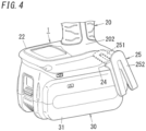
- a suspension fitting 25 for use to suspend the electric tool 1 from, for example, a working belt 120 (see FIG. 5 ) of the user 100 of the electric tool 1 is attached to the battery attachment portion 22.
- the suspension fitting 25 includes a fixing portion 251 to be inserted into a hole 24 provided through a side surface of the battery attachment portion 22 and fixed thereto with a screw, for example, and a U-hook 252, one end portion of which is coupled to the fixing portion 251. Hooking the hook 252 on his or her working belt 120, for example, allows the user 100 to move or do some type of work other than the machining work that requires the use of the electric tool 1, while suspending the electric tool 1 from the working belt 120.
- the body portion 10 is connected to one end portion 201 and the battery pack 30 is attached to the other end portion 202.
- the suspension fitting 25 for use to suspend the electric tool 1 from an object is attached to the end portion 202, to which the battery pack 30 is attached, of the grip portion 20.
- the respective weights of the body portion 10 and the battery pack 30 are set such that the battery pack 30 is heavier than the body portion 10. Since the battery pack 30 is heavier than the body portion 10, the center of mass of the electric tool 1 is located in a part, proximate to the battery pack 30, of the grip portion 20.
- the suspension fitting 25 is attached to the end portion 202, to which the battery pack 30 is attached, of the grip portion 20, thus allowing the electric tool 1 to be suspended from a position close to the center of mass of the electric tool 1. This may reduce, while the user 100 is moving or doing some other type of work with the electric tool 1 suspended from a working belt 120, the chances of the electric tool 1 being shaken significantly around the suspension fitting 25. This may reduce the chances of the electric tool 1 suspended obstructing the user's 100 movement or doing some other type of work.
- the electric tool 1 will hit the ground with the battery pack 30, which is heavier than the body portion 10, facing down. That is to say, the battery pack 30 of the electric tool 1 will hit the ground 2 earlier than the body portion 10 thereof, thus allowing the battery pack 30 to receive the impact caused by the fall.
- This may reduce the impact applied to the driving unit 12 and the transmission unit 13. Consequently, this achieves the advantage of reducing the frequency of occurrence of failures caused in the driving unit 12 and the transmission unit 13.
- the suspension fitting 25 is provided for the grip portion 20.
- the suspension fitting 25 may be attached to the body portion 10.
- the electric tool 1 may further include the suspension fitting 25 which is attached to at least one of the body portion 10 or the grip portion 20 to suspend the electric tool 1 from an object. This allows the electric tool 1 to be held suspended from the object.
- the battery pack 30 serving as a power supply for the electric tool 1 will be described with reference to FIGS. 1-7 .
- the battery pack 30 serves as a power supply that allows the electric tool 1 to operate.
- the battery pack 30 includes the power storage unit 36 including the all-solid-state batteries 35 and the battery case 31 to house the power storage unit 36 therein.
- the battery case 31 is a molded product of a synthetic resin having electrical insulation properties and is formed in the shape of a box.
- a rectangular parallelepiped fitting portion 32 which is raised by one step with respect to right and left side portions, is provided along a centerline in the rightward/leftward direction as shown in FIG. 6 .
- three slits 321 are provided to be spaced apart from each other in the rightward/leftward direction.
- Each slit 321 is provided through the front and upper surfaces of the fitting portion 32 and extends in the forward/backward direction.
- a connection terminal portion 33 to be electrically connected to a feeder connection terminal provided in a lower part of the grip portion 20.
- Each connection terminal portion 33 is electrically connected to the power storage unit 36 housed inside the battery case 31.
- a second connector 34 to be electrically connected to a first connector for transmitting signals, which is provided in a lower part of the grip portion 20.
- the second connector 34 is electrically connected to, for example, a circuit board 39 (see FIG. 1 ) housed inside the battery case 31.
- the circuit board 39 acquires battery information about the battery pack 30 (such as the voltage value and temperature of the power storage unit 36) and outputs the battery information to the control unit 14 provided inside the battery attachment portion 22.
- the right and left side surfaces of the fitting portion 32 have a plurality of insert grooves 37, to which a plurality of hook pieces 26 (see FIG. 4 ) provided inside a recess on the lower surface of the battery attachment portion 22 are respectively inserted.
- the tool body 50 is moved downward (as indicated by the arrow A1 in FIG. 3 ) from over the battery pack 30 as shown in FIG. 3 , thereby inserting the fitting portion 32 of the battery pack 30 into the recess on the lower surface of the battery attachment portion 22. Thereafter, sliding the tool body 50 forward (as indicated by the arrow A2 in FIG. 3 ) with respect to the battery pack 30 allows the hook pieces 26 of the battery attachment portion 22 to be inserted into the insert grooves 37.
- a lock piece 38 is disposed behind the frontmost one of the plurality of insert grooves 37. The lock piece 38 is biased upward by an elastic member such as a spring.
- the lock piece 38 When the battery pack 30 is attached to the battery attachment portion 22, the lock piece 38 is pressed downward by the hook piece 26, thus allowing the hook piece 26 to move inside the insert groove 37. Thereafter, when the hook piece 26 reaches the deepest part of the insert groove 37, the lock piece 38 is pressed by the spring to move upward and reach the vicinity of the rear opening of the insert groove 37. As a result, attempting to slide the tool body 50 backward with respect to the battery pack 30 brings the hook piece 26 inserted into the front insert groove 37 into contact with the lock piece 38, thus regulating the backward slide of the tool body 50. This allows the battery pack 30 to be kept attached to the battery attachment portion 22.
- connection terminal portion 33 is electrically connected to the connection terminals of the battery attachment portion 22 and power required for operation is supplied from the power storage unit 36 to the control unit 14, the driving unit 12, and other components.
- the second connector 34 is electrically connected to the first connector of the battery attachment portion 22, the circuit board 39 housed in the battery case 31 and the control unit 14 are also electrically connected to each other, and the battery information is output from the circuit board 39 to the control unit 14.
- an operating member provided for the battery case 31 is operated to move the lock piece 38 downward and make the hook pieces 26 ready to move out of the insert grooves 37.
- the tool body 50 is slid backward (i.e., in the direction opposite from the one indicated by the arrow A2 in FIG. 3 ) with respect to the battery pack 30 to move the hook pieces 26 out of the insert grooves 37.
- moving the tool body 50 upward i.e., in the direction opposite from the one indicated by the arrow A1 in FIG. 3
- the battery pack 30 allows the battery pack 30 to be removed from the tool body 50.
- the battery pack 30 is attachable to, and removable from, the grip portion 20 (of the tool body 50).
- the grip portion 20 of the tool body 50.
- the user just needs to remove the battery pack 30 from the grip portion 20 and attach a charged battery pack 30 as a replacement to the grip portion 20. This allows the user to continue his or her machining work using the electric tool 1.
- the battery pack 30 is attached to the end portion 202 of the grip portion 20 which is located adjacent to the little finger 111 of the user 100 who grips the grip portion 20 as shown in FIG. 2 .
- the end portion 201, located adjacent to the thumb of the user 100, of the grip portion 20 is connected to the body portion 10, thus achieving the advantage of allowing the user 100 to focus on the target more easily with his or her eyes while he or she is doing machining work with the tool 40 brought into contact with the workpiece.
- the respective weights of the battery pack 30 and the body portion 10 are set such that the battery pack 30 is heavier than the body portion 10.
- the battery pack 30 may be made heavier than the body portion 10 by increasing the weight of the power storage unit 36 by increasing the number of the all-solid-state batteries 35 included in the power storage unit 36, for example.
- the battery pack 30 may be made heavier than the body portion 10 by reducing the weight of the body portion 10 with either the driving unit 12 or the transmission unit 13 made lighter in weight.
- the power storage unit 36 is made up of all-solid-state batteries 35, each of which is lighter in weight than a liquid battery such as a lithium-ion battery.
- the battery pack 30 may be made heavier than the body portion 10 by either increasing the number of the all-solid-state batteries 35 or increasing the size of each of the all-solid-state batteries 35.
- the power storage unit 36 is made up of a plurality of all-solid-state batteries 35, each of which is formed in a sheet shape as shown in FIGS. 1 and 6 .
- the plurality of all-solid-state batteries 35 are connected in either series or parallel according to the voltage or capacity required.
- the power storage unit 36 includes five all-solid-state batteries 35 which are connected together in series.
- the number and connection mode (which is either series or parallel) of the all-solid-state batteries 35 that form the power storage unit 36 may be changed as appropriate according to the voltage or capacity required.
- the body portion 10 is connected to one end portion 201 and the battery pack 30 is attached to the other end portion 202.
- the electric tool 1 of this type may stand by itself in its entirety (i.e., including the body portion 10, grip portion 20, and battery pack 30 thereof) with the bottom surface 311, opposite from the grip portion 20, of the battery pack 30 put on the ground 2 (mounting surface) as shown in FIG. 1 .
- the battery pack 30 includes the connection terminal portion 33 to be electrically connected to the driving unit 12 when the battery pack 30 is attached to the grip portion 20 and the power storage unit 36 electrically connected to the connection terminal portion 33.
- the power storage unit 36 includes a plurality of all-solid-state batteries 35, each of which is formed in a sheet shape, and which are stacked one on top of another. In this case, if impact force is applied to the power storage unit 36 perpendicularly to the direction in which the all-solid-state batteries 35 are stacked one on top of another, then peeling or misalignment will occur between the plurality of all-solid-state batteries 35 that are stacked one on top of another, thus possibly causing instability in electrical connection between the plurality of all-solid-state batteries 35.
- the direction in which the plurality of all-solid-state batteries 35 are stacked one on top of another is aligned with the line that connects together the two end portions 201, 202, interposing the gripping part 21 between them, of the grip portion 20 (i.e., the Z-axis direction). This reduces the damage to be done to the power storage unit 36 by the impact applied to the power storage unit 36 in the direction aligned with the Z-axis direction.
- the direction in which the plurality of all-solid-state batteries 35 are stacked one on top of another is aligned with a direction perpendicular to the bottom surface 311 of the battery pack 30.
- the "direction perpendicular to the bottom surface 311" refers to the direction perpendicular to the mounting surface (e.g., the ground surface 2) on which the electric tool 1 is mounted (i.e., the upward/downward direction) and is the Z-axis direction shown in FIG. 1 .
- the number, area, and connection mode of the all-solid-state batteries 35 that form the power storage unit 36 may be changed as appropriate according to the voltage and capacity required.
- the voltage value of the power storage unit 36 depends on, for example, the voltage values of the respective all-solid-state batteries 35 and the number of the all-solid-state batteries 35 that are connected together in series.
- the capacity of the power storage unit 36 depends on, for example, the respective areas of the all-solid-state batteries 35 and the number of the all-solid-state batteries 35 that are connected together in parallel.
- FIG. 7 is a side view of a battery pack 30B including a power storage unit 36 in which eight all-solid-state batteries 35 are connected together in series.
- this battery pack 30B a larger number of all-solid-state batteries 35 are connected together in series than in the battery pack 30 described above, and therefore, the voltage when the battery pack 30B is fully charged is set at a higher voltage than in the battery pack 30.
- the number of the battery packs of different types does not have to be two. Rather, multiple different types of battery packs 30, of which respective voltage values and/or capacities are different from each other, are suitably prepared. In that case, one battery pack 30, selected from the multiple different types of battery packs 30, may be attached to the grip portion 20 (of the tool body 50). This allows the electric tool 1 to be used with a battery pack 30 with any desired voltage value or capacity attached to the grip portion 20.
- each of the plurality of all-solid-state batteries 35 has a rectangular sheet shape. As shown in FIG. 6 , the longitudinal axis of the plurality of all-solid-state batteries 35 is aligned with the orientation of the tool 40 attached to the tool attachment member 11 (i.e., the forward/backward direction in this embodiment). That is to say, the plurality of all-solid-state batteries 35 are arranged such that their longer side 35A is aligned with the X-axis direction and their shorter side 35B is aligned with the Y-axis direction.
- the electric tool 1 according to this embodiment is made usable by attaching the battery pack 30 to the battery attachment portion 22 of the grip portion 20.
- a tool 40 suitable for the type of the machining work that the user 100 is going to do is attached by the user 100 to the tool attachment member 11.
- control unit 14 keeps the driving unit 12 deactivated and does not rotate the tool attachment member 11.
- the control unit 14 starts driving the driving unit 12 in rotation, thereby turning the tool 40 attached to the tool attachment member 11.
- the control unit 14 controls, based on the manipulative variable of the operation of pulling the trigger 23, the rotational velocity of the driving unit 12 (i.e., the rotational velocity of the tool attachment member 11). This allows the user 100 to have any desired type of machining work done using the electric tool 1 by performing the operation of pulling the trigger 23.
- the electric tool 1 is a so-called "gun type" electric tool.
- gun type electric tool
- the present disclosure may also be implemented as a stick-type electric tool 1A as shown in FIGS. 8-10 .
- any constituent element of the stick-type electric tool 1A having the same function as a counterpart of the gun-type electric tool 1 described above, will be designated by the same reference numeral as that counterpart's, and illustration and description thereof will be omitted herein.
- a cylindrical body portion 10A including the tool attachment member 11 at the tip and a grip portion 20A including the gripping part 21 are coupled to each other via a hinge portion 15.
- a tool body 50A is formed by the body portion 10A and the grip portion 20A and the battery pack 30A is attached to the tool body 50A.
- the grip portion 20A is configured to be rotatable around the hinge portion 15 with respect to the body portion 10A. This allows the user to use the electric tool 1A selectively either in the shape in which the body portion 10A and the grip portion 20A are extended in straight line (see FIG. 10 ) or in the shape in which the grip portion 20A is bent to form a predetermined angle with respect to the body portion 10A (see FIG. 8 ).
- the grip portion 20A is formed in a cylindrical shape.
- the battery pack 30A is attached to the grip portion 20A.
- the battery case 31A of the battery pack 30A includes a square tube portion 312 to be inserted into the cylinder of the grip portion 20A and the power storage unit 36 is provided in the square tube portion 312.
- the power storage unit 36 includes a plurality of all-solid-state batteries 35, each of which is formed in a sheet shape, and which are stacked one on top of another in the rightward/leftward direction, for example.
- This battery pack 30 is attached to the grip portion 20A with the square tube portion 312 inserted into the cylinder of the grip portion 20A.
- a lower portion of the battery pack 30A is exposed out of the bottom of the grip portion 20A. That is to say, at the end portion 202, located opposite from the body portion 10, of the grip portion 20A, at least part of the battery pack 30A is provided.
- the connection terminal portion of the battery pack 30A is electrically connected to a feeder connection terminal provided inside the cylinder of the grip portion 20A so that power is supplied from the power storage unit 36 of the battery pack 30A to the driving unit 12, the control unit 14, and other components.
- gun-type electric tool 1 and the stick-type electric tool 1A are only exemplary shapes of the electric tool according to the present disclosure. That is to say, the shape of the electric tool may be modified as appropriate.
- a buffer member made of synthetic rubber may be provided between the inner surface of the battery case 31, 31A and the power storage unit 36 to reduce the impact applied to the power storage unit 36.
- the battery pack 30 may or may not be one of the constituent elements of the electric tool 1.
- the battery pack (30) includes an all-solid-state battery (35), thus providing an electric tool (1) which may reduce the chances of causing liquid leakage and thereby reduce the chances of causing a malfunction to the battery pack (30), compared to a situation where the battery pack (30) includes a liquid battery.
- the battery pack (30) has a heavier weight than the body portion (10). According to this aspect, if the electric tool (1) falls, the electric tool (1) will hit the ground with the battery pack (30), which is heavier than the body portion (10), facing down. This may reduce the impact applied to the body portion (10) by the fall.
- the battery pack (30) includes an all-solid-state battery (35) with higher impact resistance than a liquid battery.
- the battery pack (30) is attachable to, and removable from, the grip portion (20). This enables attaching the battery pack (30) to the grip portion (20) provided for the body portion (10).
- An electric tool (1) according to a further aspect, which may be implemented in conjunction with the claimed invention, further includes a suspension fitting (25) used to suspend the electric tool (1) from an object.
- the suspension fitting (25) is attached to at least one of the body portion (10) or the grip portion (20).
- This aspect allows the electric tool (1) to be suspended from an object by using the suspension fitting (25).
- the grip portion (20) includes: a first end portion (201); and a second end portion (202) located opposite from the first end portion (201) with respect to the gripping part (21).
- the body portion (10) is connected to the first end portion (201).
- the battery pack (30) is attached to the second end portion (202).
- a suspension fitting (25) for use to suspend the electric tool (1) from an object is attached to the second end portion (202), to which the battery pack (30) is attached, of the grip portion (20).
- the battery pack (30) is heavier than the body portion (10), and therefore, the center of mass of the electric tool (1) is located in a part, proximate to the battery pack (30), of the grip portion (20).
- the suspension fitting (25) is attached to the second end portion (202), to which the battery pack (30) is attached, of the grip portion (20), thus allowing the electric tool (1) to be suspended from a position close to the center of mass of the electric tool (1). This may reduce, when the user (100) is moving or doing some other type of work with the electric tool (1) suspended from a working belt (120) via the suspension fitting (25), the chances of the electric tool (1) being shaken significantly.
- the battery pack (30) includes an all-solid-state battery (35), thus providing a battery pack (30) which may reduce the chances of causing liquid leakage and thereby reduce the chances of causing a malfunction to itself, compared to a situation where the battery pack (30) includes a liquid battery.
- constituent elements according to the above aspects are not essential constituent elements for the electric tool (1) but may be omitted as appropriate.
Landscapes
- General Chemical & Material Sciences (AREA)
- Electrochemistry (AREA)
- Chemical & Material Sciences (AREA)
- Chemical Kinetics & Catalysis (AREA)
- Engineering & Computer Science (AREA)
- Mechanical Engineering (AREA)
- Biophysics (AREA)
- Computer Hardware Design (AREA)
- Life Sciences & Earth Sciences (AREA)
- Manufacturing & Machinery (AREA)
- Power Engineering (AREA)
- Battery Mounting, Suspending (AREA)
- Portable Power Tools In General (AREA)
- Secondary Cells (AREA)
Description
- The present disclosure generally relates to an electric tool and a battery pack, and more particularly relates to an electric tool powered by a battery and a battery pack.
-
Patent Literature 1 discloses a rotary tool as a type of electric tool. The housing of this rotary tool is made up of: a cylinder portion that houses a motor and a driving unit to be driven in rotation by the motor; and a grip portion provided to protrude from the cylinder portion. A battery pack serving as a power supply for the rotary tool is attached to the grip portion. - If the battery pack includes a liquid battery such as a lithium-ion battery, then application of impact to the battery pack could cause leakage of liquid from the liquid battery.
EP 2 062 310 B1
US 2019/252728 A1 describes a solid battery including at least one first laminate body in which a first electrolyte layer, a first positive electrode layer, a first current collecting layer, and a second positive electrode layer are laminated in this order; at least one second laminate body in which a second electrolyte layer, a first negative electrode layer, a second current collecting layer, and a second negative electrode layer are laminated in this order; a first insulating layer connected to at least part of a side surface portion of the first laminate body; and a second insulating layer connected to at least part of a side surface portion of the second laminate body. - Patent Literature 1:
JP 2005-169532 A - An object of the present disclosure is to provide an electric tool that may reduce the chances of causing a malfunction to its battery pack and such a battery pack.
- The claimed invention is defined by the features set forth in the appended independent claim. Particular embodiments are set forth in the dependent claims.
-
-
FIG. 1 is a side view of an electric tool according to an exemplary embodiment of the present disclosure; -
FIG. 2 illustrates a state where the electric tool is used; -
FIG. 3 is a side view illustrating a state where a battery pack is yet to be attached to a grip portion of the electric tool; -
FIG. 4 is a perspective view of a main part of the electric tool; -
FIG. 5 illustrates a state where the electric tool is used; -
FIG. 6 is a perspective view of a battery pack included in the electric tool; -
FIG. 7 is a side view of another battery pack included in the electric tool; -
FIG. 8 is a perspective view of an electric tool according to a variation of the exemplary embodiment of the present disclosure; -
FIG. 9 is a perspective view illustrating a state where a battery pack is yet to be attached to a grip portion of the electric tool; and -
FIG. 10 is a perspective view illustrating a state where the electric tool has been changed into a straight shape. - An
electric tool 1 according to an exemplary embodiment is a handheld electric tool as shown inFIGS. 1-3 . Theelectric tool 1 may be implemented as, for example, an electric screwdriver, an electric drill, an electric wrench, or an electric grinder. - The
electric tool 1 according to this embodiment includes abody portion 10, agrip portion 20, and abattery pack 30. - The
body portion 10 includes: atool attachment member 11 to which atool 40 is attached; adriving unit 12 to drive thetool 40; and atransmission unit 13 to transmit the driving force of thedriving unit 12 to thetool 40. - The
grip portion 20 is provided for thebody portion 10 and includes agripping part 21 designed to be held by auser 100 with his or herhand 110. - The battery pack 30 supplies power to the
driving unit 12. Thebattery pack 30 includes an all-solid-state battery 35. - The all-solid-
state battery 35 is a battery in which a solid electrolyte is in charge of conduction of ions between its anode and cathode. Using the all-solid-state battery 35 reduces the chances of causing leakage of the electrolyte, compared to using a liquid battery. Consequently, anelectric tool 1 that may reduce the chances of causing a malfunction to thebattery pack 30 may be provided. In the following description of this exemplary embodiment, anelectric tool 1 of the shape in which out of twoend portions gripping part 21 between them, of thegrip portion 20, oneend portion 201 is connected to thebody portion 10 and thebattery pack 30 is attached to the other end portion 202 (i.e., a so-called "gun type" electric tool 1) will be described. - The
battery pack 30 provided for theelectric tool 1 includes abattery case 31 to house the all-solid-state battery 35 therein. - The
battery pack 30 includes the all-solid-state battery 35, thus providing abattery pack 30 which may reduce the chances of causing leakage of the electrolyte and thereby reduce the chances of causing a malfunction to itself, compared to a situation where thebattery pack 30 includes a liquid battery. - Next, the configuration of an electric tool according to an exemplary embodiment will be described in detail with reference to
FIGS. 1-7 . Note that the numerical values, shapes, materials, positions of constituent elements, relative positions between the constituent elements, their connection, and other specifics to be described below are all examples and should not be construed as limiting the scope of the present disclosure. The drawings to be referred to in the following description of embodiments are all schematic representations. That is to say, the ratio of the dimensions (including thicknesses) of respective constituent elements illustrated on the drawings does not always reflect their actual dimensional ratio. Also, in the following description, the X-axis direction and Z-axis direction shown inFIGS. 1 ,3 , and6 will define the forward/backward direction and upward/downward direction, respectively, and the Y-axis direction shown inFIG. 6 will define the rightward/leftward direction. More specifically, the positive X-axis direction will define the forward direction, the positive Y-axis direction will define the rightward direction, and the positive Z-axis direction will define the upward direction. However, these directions are only examples and should not be construed as limiting the direction in which theelectric tool 1 is used. Furthermore, the arrows shown on the drawings to indicate the respective directions are just given there as an assistant to description and are insubstantial ones. - The
electric tool 1 includes thebody portion 10, thegrip portion 20, and thebattery pack 30 as shown inFIGS. 1-7 . In this embodiment, thebody portion 10 and thegrip portion 20 are provided integrally with each other and atool body 50 is made up of thebody portion 10 and thegrip portion 20. - First, the
tool body 50 made up of thebody portion 10 and thegrip portion 20 will be described. - The
body portion 10 may be, for example, a molded product of a synthetic resin with electrical insulation properties. Thebody portion 10 is formed in the shape of a cylinder extending in the forward/backward direction. - At the frontend of the
body portion 10, provided is thetool attachment member 11, to which atool 40 such as a tip tool is attached. Inside thebody portion 10, housed are thedriving unit 12 and thetransmission unit 13 described above. - The
tool attachment member 11 is provided for thebody portion 10 to be rotatable around a rotational axis aligned with the forward/backward direction. Multiple different types oftools 40 are provided for various types of machining work to be done using thiselectric tool 1. Any desired one of thetools 40 may be selectively attached to thetool attachment member 11 and used to have an intended type of machining work done. Examples of such types oftools 40 include a screwdriver bit for fastening a screw, a drill bit for drilling a hole, and a socket for fastening a nut. - The driving
unit 12 includes an electric motor to be driven with the electric power supplied from thebattery pack 30. - The
transmission unit 13 transmits the driving force of the drivingunit 12 to thetool attachment member 11. Thetransmission unit 13 is coupled to an output shaft of the drivingunit 12 and transmits the rotational force of the drivingunit 12 to thetool attachment member 11, thereby rotating thetool attachment member 11. Optionally, thetransmission unit 13 may include a speed reducer mechanism, a clutch mechanism, and an impact mechanism, for example. - The
grip portion 20 extends downward from a part of the peripheral surface of thebody portion 10. The longitudinal axis of thegrip portion 20 is aligned with the upward/downward direction. At the middle of thegrip portion 20 in the upward/downward direction (at the middle of its length), provided is thegripping part 21 to be held by the user with his or her hand 110 (seeFIG. 2 ). The part surrounded with the two-dot chain L1 (seeFIG. 1 ) of thegrip portion 20 is thegripping part 21. Thegrip portion 20 includes twoend portions gripping part 21. Theupper end portion 201 is connected to thebody portion 10. At thelower end portion 202, provided is abattery attachment portion 22 to which thebattery pack 30 is attached. - A
trigger 23 is provided on a front portion of thegripping part 21 of thegrip portion 20 to be located adjacent to theend portion 201 connected to thebody portion 10. Thetrigger 23 is an operating member that accepts an operating command entered by the user to control the rotation of the drivingunit 12. Thetrigger 23 is operated by the user with the index finger, for example, of his or herhand 110 holding thegrip portion 20. - The
battery attachment portion 22 is provided integrally with thelower end portion 202 of thegrip portion 20. Thebattery attachment portion 22 is formed to protrude perpendicularly to the upward/downward direction from thelower end portion 202 of thegrip portion 20. Thebattery attachment portion 22 is formed in the shape of a box, of which the dimension in the upward/downward direction is smaller than its dimension in the forward/backward direction and its dimension in the rightward/leftward direction. To the bottom of thebattery attachment portion 22, thebattery pack 30 is attached removably. The lower surface of thebattery attachment portion 22 is provided with a recess into which an upper portion of thebattery pack 30 is inserted. - In this embodiment, a control unit 14 (see
FIG. 1 ), including a circuit board on which a circuit for controlling the drivingunit 12 and other components are mounted, is housed inside thebattery attachment portion 22. In response to the operation of pulling thetrigger 23, thecontrol unit 14 may switch the ON/OFF states of the drivingunit 12. In addition, according to the manipulative variable of the operation of pulling the trigger 23 (i.e., depending on how deep thetrigger 23 has been pulled), thecontrol unit 14 also controls the rotational velocity of the driving unit 12 (i.e., the rotational velocity of thetool 40 attached to the tool attachment member 11). - In addition, a suspension fitting 25 (see
FIG. 4 ) for use to suspend theelectric tool 1 from, for example, a working belt 120 (seeFIG. 5 ) of theuser 100 of theelectric tool 1 is attached to thebattery attachment portion 22. The suspension fitting 25 includes a fixingportion 251 to be inserted into ahole 24 provided through a side surface of thebattery attachment portion 22 and fixed thereto with a screw, for example, and a U-hook 252, one end portion of which is coupled to the fixingportion 251. Hooking thehook 252 on his or her workingbelt 120, for example, allows theuser 100 to move or do some type of work other than the machining work that requires the use of theelectric tool 1, while suspending theelectric tool 1 from the workingbelt 120. - That is to say, in this embodiment, out of the two
end portions gripping part 21 between themselves, of thegrip portion 20, thebody portion 10 is connected to oneend portion 201 and thebattery pack 30 is attached to theother end portion 202. The suspension fitting 25 for use to suspend theelectric tool 1 from an object is attached to theend portion 202, to which thebattery pack 30 is attached, of thegrip portion 20. In this embodiment, the respective weights of thebody portion 10 and thebattery pack 30 are set such that thebattery pack 30 is heavier than thebody portion 10. Since thebattery pack 30 is heavier than thebody portion 10, the center of mass of theelectric tool 1 is located in a part, proximate to thebattery pack 30, of thegrip portion 20. The suspension fitting 25 is attached to theend portion 202, to which thebattery pack 30 is attached, of thegrip portion 20, thus allowing theelectric tool 1 to be suspended from a position close to the center of mass of theelectric tool 1. This may reduce, while theuser 100 is moving or doing some other type of work with theelectric tool 1 suspended from a workingbelt 120, the chances of theelectric tool 1 being shaken significantly around the suspension fitting 25. This may reduce the chances of theelectric tool 1 suspended obstructing the user's 100 movement or doing some other type of work. - In addition, even if the suspension fitting 25 comes loose from the working
belt 120 to let theelectric tool 1 fall while theelectric tool 1 is suspended from the workingbelt 120 as shown inFIG. 5 , theelectric tool 1 will hit the ground with thebattery pack 30, which is heavier than thebody portion 10, facing down. That is to say, thebattery pack 30 of theelectric tool 1 will hit theground 2 earlier than thebody portion 10 thereof, thus allowing thebattery pack 30 to receive the impact caused by the fall. This may reduce the impact applied to the drivingunit 12 and thetransmission unit 13. Consequently, this achieves the advantage of reducing the frequency of occurrence of failures caused in the drivingunit 12 and thetransmission unit 13. - In this embodiment, the suspension fitting 25 is provided for the
grip portion 20. Alternatively, the suspension fitting 25 may be attached to thebody portion 10. That is to say, theelectric tool 1 may further include the suspension fitting 25 which is attached to at least one of thebody portion 10 or thegrip portion 20 to suspend theelectric tool 1 from an object. This allows theelectric tool 1 to be held suspended from the object. - The
battery pack 30 serving as a power supply for theelectric tool 1 will be described with reference toFIGS. 1-7 . - The
battery pack 30 serves as a power supply that allows theelectric tool 1 to operate. Thebattery pack 30 includes thepower storage unit 36 including the all-solid-state batteries 35 and thebattery case 31 to house thepower storage unit 36 therein. Thebattery case 31 is a molded product of a synthetic resin having electrical insulation properties and is formed in the shape of a box. - In the upper part of the
battery case 31, a rectangularparallelepiped fitting portion 32, which is raised by one step with respect to right and left side portions, is provided along a centerline in the rightward/leftward direction as shown inFIG. 6 . At the frontend of thefitting portion 32, threeslits 321 are provided to be spaced apart from each other in the rightward/leftward direction. Eachslit 321 is provided through the front and upper surfaces of thefitting portion 32 and extends in the forward/backward direction. Inside each slit 321, provided is aconnection terminal portion 33 to be electrically connected to a feeder connection terminal provided in a lower part of thegrip portion 20. Eachconnection terminal portion 33 is electrically connected to thepower storage unit 36 housed inside thebattery case 31. In addition, on the upper surface of thefitting portion 32, provided is asecond connector 34 to be electrically connected to a first connector for transmitting signals, which is provided in a lower part of thegrip portion 20. Thesecond connector 34 is electrically connected to, for example, a circuit board 39 (seeFIG. 1 ) housed inside thebattery case 31. Thecircuit board 39 acquires battery information about the battery pack 30 (such as the voltage value and temperature of the power storage unit 36) and outputs the battery information to thecontrol unit 14 provided inside thebattery attachment portion 22. Furthermore, the right and left side surfaces of thefitting portion 32 have a plurality ofinsert grooves 37, to which a plurality of hook pieces 26 (seeFIG. 4 ) provided inside a recess on the lower surface of thebattery attachment portion 22 are respectively inserted. - In this embodiment, to attach the
battery pack 30 to thebattery attachment portion 22, thetool body 50 is moved downward (as indicated by the arrow A1 inFIG. 3 ) from over thebattery pack 30 as shown inFIG. 3 , thereby inserting thefitting portion 32 of thebattery pack 30 into the recess on the lower surface of thebattery attachment portion 22. Thereafter, sliding thetool body 50 forward (as indicated by the arrow A2 inFIG. 3 ) with respect to thebattery pack 30 allows thehook pieces 26 of thebattery attachment portion 22 to be inserted into theinsert grooves 37. Alock piece 38 is disposed behind the frontmost one of the plurality ofinsert grooves 37. Thelock piece 38 is biased upward by an elastic member such as a spring. When thebattery pack 30 is attached to thebattery attachment portion 22, thelock piece 38 is pressed downward by thehook piece 26, thus allowing thehook piece 26 to move inside theinsert groove 37. Thereafter, when thehook piece 26 reaches the deepest part of theinsert groove 37, thelock piece 38 is pressed by the spring to move upward and reach the vicinity of the rear opening of theinsert groove 37. As a result, attempting to slide thetool body 50 backward with respect to thebattery pack 30 brings thehook piece 26 inserted into thefront insert groove 37 into contact with thelock piece 38, thus regulating the backward slide of thetool body 50. This allows thebattery pack 30 to be kept attached to thebattery attachment portion 22. - In a state where the
battery pack 30 is attached to thebattery attachment portion 22, theconnection terminal portion 33 is electrically connected to the connection terminals of thebattery attachment portion 22 and power required for operation is supplied from thepower storage unit 36 to thecontrol unit 14, the drivingunit 12, and other components. In addition, thesecond connector 34 is electrically connected to the first connector of thebattery attachment portion 22, thecircuit board 39 housed in thebattery case 31 and thecontrol unit 14 are also electrically connected to each other, and the battery information is output from thecircuit board 39 to thecontrol unit 14. - On the other hand, to remove the
battery pack 30 from thebattery attachment portion 22, an operating member provided for thebattery case 31 is operated to move thelock piece 38 downward and make thehook pieces 26 ready to move out of theinsert grooves 37. In this state, thetool body 50 is slid backward (i.e., in the direction opposite from the one indicated by the arrow A2 inFIG. 3 ) with respect to thebattery pack 30 to move thehook pieces 26 out of theinsert grooves 37. Then, moving thetool body 50 upward (i.e., in the direction opposite from the one indicated by the arrow A1 inFIG. 3 ) with respect to thebattery pack 30 allows thebattery pack 30 to be removed from thetool body 50. - As can be seen, according to this embodiment, the
battery pack 30 is attachable to, and removable from, the grip portion 20 (of the tool body 50). Thus, when the battery level of thebattery pack 30 becomes low, the user just needs to remove thebattery pack 30 from thegrip portion 20 and attach a chargedbattery pack 30 as a replacement to thegrip portion 20. This allows the user to continue his or her machining work using theelectric tool 1. - Furthermore, the
battery pack 30 is attached to theend portion 202 of thegrip portion 20 which is located adjacent to thelittle finger 111 of theuser 100 who grips thegrip portion 20 as shown inFIG. 2 . Thus, theend portion 201, located adjacent to the thumb of theuser 100, of thegrip portion 20 is connected to thebody portion 10, thus achieving the advantage of allowing theuser 100 to focus on the target more easily with his or her eyes while he or she is doing machining work with thetool 40 brought into contact with the workpiece. - Note that in this embodiment, the respective weights of the
battery pack 30 and thebody portion 10 are set such that thebattery pack 30 is heavier than thebody portion 10. Thebattery pack 30 may be made heavier than thebody portion 10 by increasing the weight of thepower storage unit 36 by increasing the number of the all-solid-state batteries 35 included in thepower storage unit 36, for example. Alternatively, thebattery pack 30 may be made heavier than thebody portion 10 by reducing the weight of thebody portion 10 with either the drivingunit 12 or thetransmission unit 13 made lighter in weight. In this embodiment, thepower storage unit 36 is made up of all-solid-state batteries 35, each of which is lighter in weight than a liquid battery such as a lithium-ion battery. Thebattery pack 30 may be made heavier than thebody portion 10 by either increasing the number of the all-solid-state batteries 35 or increasing the size of each of the all-solid-state batteries 35. - The
power storage unit 36 is made up of a plurality of all-solid-state batteries 35, each of which is formed in a sheet shape as shown inFIGS. 1 and6 . The plurality of all-solid-state batteries 35 are connected in either series or parallel according to the voltage or capacity required. In this embodiment, thepower storage unit 36 includes five all-solid-state batteries 35 which are connected together in series. However, the number and connection mode (which is either series or parallel) of the all-solid-state batteries 35 that form thepower storage unit 36 may be changed as appropriate according to the voltage or capacity required. - As described above, out of the two
end portions gripping part 21 between them, of thegrip portion 20, thebody portion 10 is connected to oneend portion 201 and thebattery pack 30 is attached to theother end portion 202. Theelectric tool 1 of this type may stand by itself in its entirety (i.e., including thebody portion 10,grip portion 20, andbattery pack 30 thereof) with thebottom surface 311, opposite from thegrip portion 20, of thebattery pack 30 put on the ground 2 (mounting surface) as shown inFIG. 1 . Thebattery pack 30 includes theconnection terminal portion 33 to be electrically connected to the drivingunit 12 when thebattery pack 30 is attached to thegrip portion 20 and thepower storage unit 36 electrically connected to theconnection terminal portion 33. Thepower storage unit 36 includes a plurality of all-solid-state batteries 35, each of which is formed in a sheet shape, and which are stacked one on top of another. In this case, if impact force is applied to thepower storage unit 36 perpendicularly to the direction in which the all-solid-state batteries 35 are stacked one on top of another, then peeling or misalignment will occur between the plurality of all-solid-state batteries 35 that are stacked one on top of another, thus possibly causing instability in electrical connection between the plurality of all-solid-state batteries 35. On the other hand, if impact force is applied to thepower storage unit 36 in the direction in which the all-solid-state batteries 35 are stacked one on top of another, then peeling or misalignment will rarely occur between the plurality of all-solid-state batteries 35 that are stacked one on top of another, thus reducing the chances of causing instability in electrical connection between the plurality of all-solid-state batteries 35. In this embodiment, the direction in which the plurality of all-solid-state batteries 35 are stacked one on top of another is aligned with the line that connects together the twoend portions gripping part 21 between them, of the grip portion 20 (i.e., the Z-axis direction). This reduces the damage to be done to thepower storage unit 36 by the impact applied to thepower storage unit 36 in the direction aligned with the Z-axis direction. - Furthermore, in this embodiment, the direction in which the plurality of all-solid-
state batteries 35 are stacked one on top of another is aligned with a direction perpendicular to thebottom surface 311 of thebattery pack 30. As used herein, the "direction perpendicular to thebottom surface 311" refers to the direction perpendicular to the mounting surface (e.g., the ground surface 2) on which theelectric tool 1 is mounted (i.e., the upward/downward direction) and is the Z-axis direction shown inFIG. 1 . Therefore, if theelectric tool 1 is put with impetus onto the mounting surface, then impact force is applied in the direction in which the plurality of all-solid-state batteries 35 are stacked one on top of another, thus reducing the chances of causing peeling or misalignment between the plurality of all-solid-state batteries 35 that are stacked one on top of another. This may reduce the chances of causing deterioration in the electrical performance of thebattery pack 30. - Also, in this
battery pack 30, the number, area, and connection mode of the all-solid-state batteries 35 that form thepower storage unit 36 may be changed as appropriate according to the voltage and capacity required. The voltage value of thepower storage unit 36 depends on, for example, the voltage values of the respective all-solid-state batteries 35 and the number of the all-solid-state batteries 35 that are connected together in series. The capacity of thepower storage unit 36 depends on, for example, the respective areas of the all-solid-state batteries 35 and the number of the all-solid-state batteries 35 that are connected together in parallel. For example,FIG. 7 is a side view of abattery pack 30B including apower storage unit 36 in which eight all-solid-state batteries 35 are connected together in series. In thisbattery pack 30B, a larger number of all-solid-state batteries 35 are connected together in series than in thebattery pack 30 described above, and therefore, the voltage when thebattery pack 30B is fully charged is set at a higher voltage than in thebattery pack 30. Note that the number of the battery packs of different types does not have to be two. Rather, multiple different types of battery packs 30, of which respective voltage values and/or capacities are different from each other, are suitably prepared. In that case, onebattery pack 30, selected from the multiple different types of battery packs 30, may be attached to the grip portion 20 (of the tool body 50). This allows theelectric tool 1 to be used with abattery pack 30 with any desired voltage value or capacity attached to thegrip portion 20. - Furthermore, each of the plurality of all-solid-
state batteries 35 has a rectangular sheet shape. As shown inFIG. 6 , the longitudinal axis of the plurality of all-solid-state batteries 35 is aligned with the orientation of thetool 40 attached to the tool attachment member 11 (i.e., the forward/backward direction in this embodiment). That is to say, the plurality of all-solid-state batteries 35 are arranged such that theirlonger side 35A is aligned with the X-axis direction and theirshorter side 35B is aligned with the Y-axis direction. This enables reducing, compared to a situation where the plurality of all-solid-state batteries 35 are arranged such that theirlonger side 35A is perpendicular to the orientation of the tool 40 (i.e., the forward/backward direction), the width of thebattery pack 30 as measured perpendicularly to the orientation of thetool 40 with thetool 40 pointed at the workpiece. - The
electric tool 1 according to this embodiment is made usable by attaching thebattery pack 30 to thebattery attachment portion 22 of thegrip portion 20. Note that atool 40 suitable for the type of the machining work that theuser 100 is going to do is attached by theuser 100 to thetool attachment member 11. - When the
user 100 has not pulled thetrigger 23 yet, thecontrol unit 14 keeps the drivingunit 12 deactivated and does not rotate thetool attachment member 11. - On the other hand, when the
user 100 pulls thetrigger 23, thecontrol unit 14 starts driving the drivingunit 12 in rotation, thereby turning thetool 40 attached to thetool attachment member 11. At this time, thecontrol unit 14 controls, based on the manipulative variable of the operation of pulling thetrigger 23, the rotational velocity of the driving unit 12 (i.e., the rotational velocity of the tool attachment member 11). This allows theuser 100 to have any desired type of machining work done using theelectric tool 1 by performing the operation of pulling thetrigger 23. - Next, variations of the exemplary embodiment described above will be enumerated one after another. Note that the variations to be described below may be adopted in combination as appropriate.
- The
electric tool 1 according to the exemplary embodiment described above is a so-called "gun type" electric tool. However, this is only an example and should not be construed as limiting. Alternatively, the present disclosure may also be implemented as a stick-typeelectric tool 1A as shown inFIGS. 8-10 . In the following description, any constituent element of the stick-typeelectric tool 1A, having the same function as a counterpart of the gun-typeelectric tool 1 described above, will be designated by the same reference numeral as that counterpart's, and illustration and description thereof will be omitted herein. - In the stick-type
electric tool 1A, acylindrical body portion 10A including thetool attachment member 11 at the tip and agrip portion 20A including thegripping part 21 are coupled to each other via ahinge portion 15. In this variation, atool body 50A is formed by thebody portion 10A and thegrip portion 20A and thebattery pack 30A is attached to thetool body 50A. - The
grip portion 20A is configured to be rotatable around thehinge portion 15 with respect to thebody portion 10A. This allows the user to use theelectric tool 1A selectively either in the shape in which thebody portion 10A and thegrip portion 20A are extended in straight line (seeFIG. 10 ) or in the shape in which thegrip portion 20A is bent to form a predetermined angle with respect to thebody portion 10A (seeFIG. 8 ). - In the stick-type
electric tool 1A, thegrip portion 20A is formed in a cylindrical shape. - The battery pack 30Ais attached to the
grip portion 20A. As shown inFIG. 8 , thebattery case 31A of thebattery pack 30A includes asquare tube portion 312 to be inserted into the cylinder of thegrip portion 20A and thepower storage unit 36 is provided in thesquare tube portion 312. Thepower storage unit 36 includes a plurality of all-solid-state batteries 35, each of which is formed in a sheet shape, and which are stacked one on top of another in the rightward/leftward direction, for example. - This
battery pack 30 is attached to thegrip portion 20A with thesquare tube portion 312 inserted into the cylinder of thegrip portion 20A. In thebattery pack 30A attached to thegrip portion 20A, a lower portion of thebattery pack 30A is exposed out of the bottom of thegrip portion 20A. That is to say, at theend portion 202, located opposite from thebody portion 10, of thegrip portion 20A, at least part of thebattery pack 30A is provided. In addition, in thebattery pack 30A attached to thegrip portion 20A, the connection terminal portion of thebattery pack 30A is electrically connected to a feeder connection terminal provided inside the cylinder of thegrip portion 20A so that power is supplied from thepower storage unit 36 of thebattery pack 30A to the drivingunit 12, thecontrol unit 14, and other components. - Note that the gun-type
electric tool 1 and the stick-typeelectric tool 1A are only exemplary shapes of the electric tool according to the present disclosure. That is to say, the shape of the electric tool may be modified as appropriate. - Optionally, in the exemplary embodiment and variations described above, a buffer member made of synthetic rubber, for example, may be provided between the inner surface of the
battery case power storage unit 36 to reduce the impact applied to thepower storage unit 36. - Furthermore, in the exemplary embodiment and variations described above, the
battery pack 30 may or may not be one of the constituent elements of theelectric tool 1. - According to the claimed invention, the battery pack (30) includes an all-solid-state battery (35), thus providing an electric tool (1) which may reduce the chances of causing liquid leakage and thereby reduce the chances of causing a malfunction to the battery pack (30), compared to a situation where the battery pack (30) includes a liquid battery. The battery pack (30) has a heavier weight than the body portion (10). According to this aspect, if the electric tool (1) falls, the electric tool (1) will hit the ground with the battery pack (30), which is heavier than the body portion (10), facing down. This may reduce the impact applied to the body portion (10) by the fall. In addition, the battery pack (30) includes an all-solid-state battery (35) with higher impact resistance than a liquid battery. This may reduce, even when impact is applied to the battery pack (30) that has fallen, the chances of causing abnormality to the battery pack (30). The battery pack (30) is attachable to, and removable from, the grip portion (20). This enables attaching the battery pack (30) to the grip portion (20) provided for the body portion (10).
- An electric tool (1) according to a further aspect, which may be implemented in conjunction with the claimed invention, further includes a suspension fitting (25) used to suspend the electric tool (1) from an object. The suspension fitting (25) is attached to at least one of the body portion (10) or the grip portion (20).
- This aspect allows the electric tool (1) to be suspended from an object by using the suspension fitting (25).
- In an electric tool (1) according to a further aspect, which may be implemented in conjunction with the claimed invention or any of the above aspects, the grip portion (20) includes: a first end portion (201); and a second end portion (202) located opposite from the first end portion (201) with respect to the gripping part (21). The body portion (10) is connected to the first end portion (201). The battery pack (30) is attached to the second end portion (202). A suspension fitting (25) for use to suspend the electric tool (1) from an object is attached to the second end portion (202), to which the battery pack (30) is attached, of the grip portion (20).
- According to this aspect, the battery pack (30) is heavier than the body portion (10), and therefore, the center of mass of the electric tool (1) is located in a part, proximate to the battery pack (30), of the grip portion (20). The suspension fitting (25) is attached to the second end portion (202), to which the battery pack (30) is attached, of the grip portion (20), thus allowing the electric tool (1) to be suspended from a position close to the center of mass of the electric tool (1). This may reduce, when the user (100) is moving or doing some other type of work with the electric tool (1) suspended from a working belt (120) via the suspension fitting (25), the chances of the electric tool (1) being shaken significantly.
- According to an aspect, the battery pack (30) includes an all-solid-state battery (35), thus providing a battery pack (30) which may reduce the chances of causing liquid leakage and thereby reduce the chances of causing a malfunction to itself, compared to a situation where the battery pack (30) includes a liquid battery.
- Note that the constituent elements according to the above aspects are not essential constituent elements for the electric tool (1) but may be omitted as appropriate.
-
- 1
- Electric Tool
- 10
- Body Portion
- 11
- Tool Attachment Member
- 12
- Driving Unit
- 13
- Transmission Unit
- 20
- Grip Portion
- 21
- Gripping Part
- 25
- Suspension Fitting
- 30
- Battery Pack
- 31
- Battery Case
- 35
- All-Solid-State Battery
- 40
- Tool
- 100
- User
- 110
- Hand
- 201, 202
- End Portion
Claims (3)
- An electric tool (1) comprising:a body portion (10) including: a tool attachment member (11) to which a tool (40) is attached; a driving unit (12) configured to drive the tool (40); and a transmission unit (13) configured to transmit driving force of the driving unit (12) to the tool (40);a grip portion (20) provided for the body portion (10) and including a gripping part (21) designed to be held by a user with his or her hand; anda battery pack (30) configured to supply power to the driving unit (12), wherein the battery pack (30) is attachable to, and removable from, the grip portion,characterized in that:
the battery pack (30) includes an all-solid-state battery (35) and has a heavier weight than the body portion (10). - The electric tool (1) of claim 1, further comprising a suspension fitting (25) attached to at least one of the body portion (10) or the grip portion (20) and used to suspend the electric tool (1) from an object.
- The electric tool (1) of claim 1, whereinthe grip portion (20) includes: a first end portion (201); and a second end portion (202) located opposite from the first end portion (201) with respect to the gripping part (21), the body portion (10) being connected to the first end portion (201), the battery pack (30) being attached to the second end portion (202), anda suspension fitting (25) for use to suspend the electric tool (1) from an object is attached to the second end portion (202), to which the battery pack (30) is attached, of the grip portion (20).
Applications Claiming Priority (2)
| Application Number | Priority Date | Filing Date | Title |
|---|---|---|---|
| JP2019179572A JP7262057B2 (en) | 2019-09-30 | 2019-09-30 | Power tools and battery packs |
| PCT/JP2020/032517 WO2021065269A1 (en) | 2019-09-30 | 2020-08-28 | Electric power tool and battery pack |
Publications (3)
| Publication Number | Publication Date |
|---|---|
| EP4039415A1 EP4039415A1 (en) | 2022-08-10 |
| EP4039415A4 EP4039415A4 (en) | 2022-11-16 |
| EP4039415B1 true EP4039415B1 (en) | 2024-06-19 |
Family
ID=75269326
Family Applications (1)
| Application Number | Title | Priority Date | Filing Date |
|---|---|---|---|
| EP20870845.3A Active EP4039415B1 (en) | 2019-09-30 | 2020-08-28 | Electric power tool and battery pack |
Country Status (5)
| Country | Link |
|---|---|
| US (1) | US12036657B2 (en) |
| EP (1) | EP4039415B1 (en) |
| JP (1) | JP7262057B2 (en) |
| CN (1) | CN114423569B (en) |
| WO (1) | WO2021065269A1 (en) |
Families Citing this family (4)
| Publication number | Priority date | Publication date | Assignee | Title |
|---|---|---|---|---|
| USD1013634S1 (en) * | 2019-09-05 | 2024-02-06 | Techtronic Cordless Gp | Battery pack |
| JPWO2022201893A1 (en) | 2021-03-26 | 2022-09-29 | ||
| CN115674071A (en) * | 2021-07-29 | 2023-02-03 | 株式会社牧田 | Electric tool and impact driver |
| SE545518C2 (en) * | 2022-02-10 | 2023-10-10 | Husqvarna Ab | Handheld battery-operated power tools, rechargeable battery packs, and methods of controlling such power tools and battery packs |
Family Cites Families (17)
| Publication number | Priority date | Publication date | Assignee | Title |
|---|---|---|---|---|
| JP4300990B2 (en) | 2003-12-09 | 2009-07-22 | パナソニック電工株式会社 | Rotating tool |
| JP4311425B2 (en) | 2006-09-07 | 2009-08-12 | 日立工機株式会社 | Battery pack, charger, and power tool |
| DE102009045945A1 (en) | 2009-10-23 | 2011-04-28 | Robert Bosch Gmbh | Electric machine tool with ultrasonic excitation |
| DE212012000140U1 (en) * | 2011-07-24 | 2014-02-26 | Makita Corporation | Hand power tools and battery packs for these |
| EP2639015A3 (en) * | 2012-03-13 | 2018-03-28 | Black & Decker Inc. | Power Tool |
| WO2014003481A1 (en) | 2012-06-28 | 2014-01-03 | 주식회사 엘지화학 | Electrode assembly and electrochemical device containing same |
| JPWO2016092888A1 (en) | 2014-12-09 | 2017-04-27 | 日本碍子株式会社 | Bendable battery module |
| JP2017147028A (en) | 2016-02-15 | 2017-08-24 | リョービ株式会社 | Battery pack |
| JP6320453B2 (en) | 2016-05-13 | 2018-05-09 | 株式会社マキタ | Electric tool set |
| JP6729716B2 (en) * | 2016-11-08 | 2020-07-22 | 株式会社村田製作所 | Solid-state battery, method of manufacturing solid-state battery, battery pack, vehicle, power storage system, power tool, and electronic device |
| GB201621312D0 (en) * | 2016-12-15 | 2017-02-01 | 7Rdd Ltd | Multi power tool system incorporating battery pack |
| WO2018203474A1 (en) * | 2017-05-01 | 2018-11-08 | 株式会社村田製作所 | Solid cell, cell pack, electric vehicle, power storage system, electric tool, and electronic device |
| JP6954350B2 (en) | 2017-07-10 | 2021-10-27 | 株式会社村田製作所 | Battery modules, container-type power storage systems, vehicles, power storage systems, power tools and electronic devices |
| WO2019111054A1 (en) | 2017-12-04 | 2019-06-13 | Robbox Inc. | Hand held power tool with laser measuring system and interactive display |
| JP6761838B2 (en) | 2018-08-30 | 2020-09-30 | 株式会社マキタ | Electric impact tool |
| US11233282B2 (en) | 2019-06-17 | 2022-01-25 | Makita Corporation | Battery-powered portable tool |
| EP3975300A4 (en) | 2019-06-20 | 2023-03-08 | Nanjing Chervon Industry Co., Ltd. | Battery pack and combination of electric tool and battery pack |
-
2019
- 2019-09-30 JP JP2019179572A patent/JP7262057B2/en active Active
-
2020
- 2020-08-28 CN CN202080065300.1A patent/CN114423569B/en active Active
- 2020-08-28 US US17/764,943 patent/US12036657B2/en active Active
- 2020-08-28 WO PCT/JP2020/032517 patent/WO2021065269A1/en not_active Ceased
- 2020-08-28 EP EP20870845.3A patent/EP4039415B1/en active Active
Also Published As
| Publication number | Publication date |
|---|---|
| US20220362920A1 (en) | 2022-11-17 |
| CN114423569A (en) | 2022-04-29 |
| JP7262057B2 (en) | 2023-04-21 |
| EP4039415A4 (en) | 2022-11-16 |
| JP2021053751A (en) | 2021-04-08 |
| CN114423569B (en) | 2024-08-27 |
| WO2021065269A1 (en) | 2021-04-08 |
| EP4039415A1 (en) | 2022-08-10 |
| US12036657B2 (en) | 2024-07-16 |
Similar Documents
| Publication | Publication Date | Title |
|---|---|---|
| EP4039416B1 (en) | Electric tool and battery pack | |
| EP4039415B1 (en) | Electric power tool and battery pack | |
| CN204204933U (en) | Power Tool System or Kit | |
| EP2625006B1 (en) | Battery retention system for a power tool | |
| US7932695B2 (en) | Power tool, battery, charger and method of operating the same | |
| CN203527418U (en) | Electric tool | |
| US20160322842A1 (en) | Charging device for a battery pack for a hand-held power tool | |
| US20140008093A1 (en) | Cordless power tool with usb charging | |
| US10797281B2 (en) | Hand-held power tool and rechargeable battery pack for a hand-held power tool | |
| GB2420029A (en) | Battery pack for a cordless power tool | |
| JP2013094877A (en) | Power tool | |
| US11811250B2 (en) | Removable battery pack and/or electrical consumer with an electromechanical interface for supplying energy | |
| EP4039417B1 (en) | Electric tool and battery pack | |
| JP6942515B2 (en) | Electrical equipment | |
| EP4099485A1 (en) | Battery pack and electric tool | |
| GB2408396A (en) | Battery pack and charge equaliser | |
| JP2013094882A (en) | Power tool |
Legal Events
| Date | Code | Title | Description |
|---|---|---|---|
| STAA | Information on the status of an ep patent application or granted ep patent |
Free format text: STATUS: THE INTERNATIONAL PUBLICATION HAS BEEN MADE |
|
| PUAI | Public reference made under article 153(3) epc to a published international application that has entered the european phase |
Free format text: ORIGINAL CODE: 0009012 |
|
| STAA | Information on the status of an ep patent application or granted ep patent |
Free format text: STATUS: REQUEST FOR EXAMINATION WAS MADE |
|
| 17P | Request for examination filed |
Effective date: 20220324 |
|
| AK | Designated contracting states |
Kind code of ref document: A1 Designated state(s): AL AT BE BG CH CY CZ DE DK EE ES FI FR GB GR HR HU IE IS IT LI LT LU LV MC MK MT NL NO PL PT RO RS SE SI SK SM TR |
|
| A4 | Supplementary search report drawn up and despatched |
Effective date: 20221019 |
|
| RIC1 | Information provided on ipc code assigned before grant |
Ipc: H01M 50/20 20210101ALI20221013BHEP Ipc: H01M 10/0562 20100101ALI20221013BHEP Ipc: B25F 5/02 20060101ALI20221013BHEP Ipc: B25F 5/00 20060101AFI20221013BHEP |
|
| DAV | Request for validation of the european patent (deleted) | ||
| DAX | Request for extension of the european patent (deleted) | ||
| STAA | Information on the status of an ep patent application or granted ep patent |
Free format text: STATUS: EXAMINATION IS IN PROGRESS |
|
| 17Q | First examination report despatched |
Effective date: 20231213 |
|
| GRAP | Despatch of communication of intention to grant a patent |
Free format text: ORIGINAL CODE: EPIDOSNIGR1 |
|
| STAA | Information on the status of an ep patent application or granted ep patent |
Free format text: STATUS: GRANT OF PATENT IS INTENDED |
|
| INTG | Intention to grant announced |
Effective date: 20240129 |
|
| GRAS | Grant fee paid |
Free format text: ORIGINAL CODE: EPIDOSNIGR3 |
|
| GRAA | (expected) grant |
Free format text: ORIGINAL CODE: 0009210 |
|
| STAA | Information on the status of an ep patent application or granted ep patent |
Free format text: STATUS: THE PATENT HAS BEEN GRANTED |
|
| AK | Designated contracting states |
Kind code of ref document: B1 Designated state(s): AL AT BE BG CH CY CZ DE DK EE ES FI FR GB GR HR HU IE IS IT LI LT LU LV MC MK MT NL NO PL PT RO RS SE SI SK SM TR |
|
| REG | Reference to a national code |
Ref country code: GB Ref legal event code: FG4D |
|
| REG | Reference to a national code |
Ref country code: CH Ref legal event code: EP |
|
| REG | Reference to a national code |
Ref country code: DE Ref legal event code: R096 Ref document number: 602020032776 Country of ref document: DE |
|
| PG25 | Lapsed in a contracting state [announced via postgrant information from national office to epo] |
Ref country code: BG Free format text: LAPSE BECAUSE OF FAILURE TO SUBMIT A TRANSLATION OF THE DESCRIPTION OR TO PAY THE FEE WITHIN THE PRESCRIBED TIME-LIMIT Effective date: 20240619 |
|
| PG25 | Lapsed in a contracting state [announced via postgrant information from national office to epo] |
Ref country code: HR Free format text: LAPSE BECAUSE OF FAILURE TO SUBMIT A TRANSLATION OF THE DESCRIPTION OR TO PAY THE FEE WITHIN THE PRESCRIBED TIME-LIMIT Effective date: 20240619 Ref country code: FI Free format text: LAPSE BECAUSE OF FAILURE TO SUBMIT A TRANSLATION OF THE DESCRIPTION OR TO PAY THE FEE WITHIN THE PRESCRIBED TIME-LIMIT Effective date: 20240619 |
|
| REG | Reference to a national code |
Ref country code: LT Ref legal event code: MG9D |
|
| PG25 | Lapsed in a contracting state [announced via postgrant information from national office to epo] |
Ref country code: GR Free format text: LAPSE BECAUSE OF FAILURE TO SUBMIT A TRANSLATION OF THE DESCRIPTION OR TO PAY THE FEE WITHIN THE PRESCRIBED TIME-LIMIT Effective date: 20240920 |
|
| REG | Reference to a national code |
Ref country code: NL Ref legal event code: MP Effective date: 20240619 |
|
| PG25 | Lapsed in a contracting state [announced via postgrant information from national office to epo] |
Ref country code: LV Free format text: LAPSE BECAUSE OF FAILURE TO SUBMIT A TRANSLATION OF THE DESCRIPTION OR TO PAY THE FEE WITHIN THE PRESCRIBED TIME-LIMIT Effective date: 20240619 |
|
| PG25 | Lapsed in a contracting state [announced via postgrant information from national office to epo] |
Ref country code: NO Free format text: LAPSE BECAUSE OF FAILURE TO SUBMIT A TRANSLATION OF THE DESCRIPTION OR TO PAY THE FEE WITHIN THE PRESCRIBED TIME-LIMIT Effective date: 20240919 Ref country code: LV Free format text: LAPSE BECAUSE OF FAILURE TO SUBMIT A TRANSLATION OF THE DESCRIPTION OR TO PAY THE FEE WITHIN THE PRESCRIBED TIME-LIMIT Effective date: 20240619 Ref country code: HR Free format text: LAPSE BECAUSE OF FAILURE TO SUBMIT A TRANSLATION OF THE DESCRIPTION OR TO PAY THE FEE WITHIN THE PRESCRIBED TIME-LIMIT Effective date: 20240619 Ref country code: GR Free format text: LAPSE BECAUSE OF FAILURE TO SUBMIT A TRANSLATION OF THE DESCRIPTION OR TO PAY THE FEE WITHIN THE PRESCRIBED TIME-LIMIT Effective date: 20240920 Ref country code: FI Free format text: LAPSE BECAUSE OF FAILURE TO SUBMIT A TRANSLATION OF THE DESCRIPTION OR TO PAY THE FEE WITHIN THE PRESCRIBED TIME-LIMIT Effective date: 20240619 Ref country code: BG Free format text: LAPSE BECAUSE OF FAILURE TO SUBMIT A TRANSLATION OF THE DESCRIPTION OR TO PAY THE FEE WITHIN THE PRESCRIBED TIME-LIMIT Effective date: 20240619 Ref country code: RS Free format text: LAPSE BECAUSE OF FAILURE TO SUBMIT A TRANSLATION OF THE DESCRIPTION OR TO PAY THE FEE WITHIN THE PRESCRIBED TIME-LIMIT Effective date: 20240919 |
|
| PG25 | Lapsed in a contracting state [announced via postgrant information from national office to epo] |
Ref country code: NL Free format text: LAPSE BECAUSE OF FAILURE TO SUBMIT A TRANSLATION OF THE DESCRIPTION OR TO PAY THE FEE WITHIN THE PRESCRIBED TIME-LIMIT Effective date: 20240619 |
|
| REG | Reference to a national code |
Ref country code: AT Ref legal event code: MK05 Ref document number: 1695646 Country of ref document: AT Kind code of ref document: T Effective date: 20240619 |
|
| PG25 | Lapsed in a contracting state [announced via postgrant information from national office to epo] |
Ref country code: NL Free format text: LAPSE BECAUSE OF FAILURE TO SUBMIT A TRANSLATION OF THE DESCRIPTION OR TO PAY THE FEE WITHIN THE PRESCRIBED TIME-LIMIT Effective date: 20240619 |
|
| PG25 | Lapsed in a contracting state [announced via postgrant information from national office to epo] |
Ref country code: PT Free format text: LAPSE BECAUSE OF FAILURE TO SUBMIT A TRANSLATION OF THE DESCRIPTION OR TO PAY THE FEE WITHIN THE PRESCRIBED TIME-LIMIT Effective date: 20241021 |
|
| PG25 | Lapsed in a contracting state [announced via postgrant information from national office to epo] |
Ref country code: PT Free format text: LAPSE BECAUSE OF FAILURE TO SUBMIT A TRANSLATION OF THE DESCRIPTION OR TO PAY THE FEE WITHIN THE PRESCRIBED TIME-LIMIT Effective date: 20241021 |
|
| PG25 | Lapsed in a contracting state [announced via postgrant information from national office to epo] |
Ref country code: PL Free format text: LAPSE BECAUSE OF FAILURE TO SUBMIT A TRANSLATION OF THE DESCRIPTION OR TO PAY THE FEE WITHIN THE PRESCRIBED TIME-LIMIT Effective date: 20240619 |
|
| PG25 | Lapsed in a contracting state [announced via postgrant information from national office to epo] |
Ref country code: EE Free format text: LAPSE BECAUSE OF FAILURE TO SUBMIT A TRANSLATION OF THE DESCRIPTION OR TO PAY THE FEE WITHIN THE PRESCRIBED TIME-LIMIT Effective date: 20240619 |
|
| PG25 | Lapsed in a contracting state [announced via postgrant information from national office to epo] |
Ref country code: IS Free format text: LAPSE BECAUSE OF FAILURE TO SUBMIT A TRANSLATION OF THE DESCRIPTION OR TO PAY THE FEE WITHIN THE PRESCRIBED TIME-LIMIT Effective date: 20241019 Ref country code: AT Free format text: LAPSE BECAUSE OF FAILURE TO SUBMIT A TRANSLATION OF THE DESCRIPTION OR TO PAY THE FEE WITHIN THE PRESCRIBED TIME-LIMIT Effective date: 20240619 |
|
| PG25 | Lapsed in a contracting state [announced via postgrant information from national office to epo] |
Ref country code: CZ Free format text: LAPSE BECAUSE OF FAILURE TO SUBMIT A TRANSLATION OF THE DESCRIPTION OR TO PAY THE FEE WITHIN THE PRESCRIBED TIME-LIMIT Effective date: 20240619 |
|
| PG25 | Lapsed in a contracting state [announced via postgrant information from national office to epo] |
Ref country code: SK Free format text: LAPSE BECAUSE OF FAILURE TO SUBMIT A TRANSLATION OF THE DESCRIPTION OR TO PAY THE FEE WITHIN THE PRESCRIBED TIME-LIMIT Effective date: 20240619 Ref country code: RO Free format text: LAPSE BECAUSE OF FAILURE TO SUBMIT A TRANSLATION OF THE DESCRIPTION OR TO PAY THE FEE WITHIN THE PRESCRIBED TIME-LIMIT Effective date: 20240619 |
|
| PG25 | Lapsed in a contracting state [announced via postgrant information from national office to epo] |
Ref country code: ES Free format text: LAPSE BECAUSE OF FAILURE TO SUBMIT A TRANSLATION OF THE DESCRIPTION OR TO PAY THE FEE WITHIN THE PRESCRIBED TIME-LIMIT Effective date: 20240619 Ref country code: SM Free format text: LAPSE BECAUSE OF FAILURE TO SUBMIT A TRANSLATION OF THE DESCRIPTION OR TO PAY THE FEE WITHIN THE PRESCRIBED TIME-LIMIT Effective date: 20240619 |
|
| PG25 | Lapsed in a contracting state [announced via postgrant information from national office to epo] |
Ref country code: SM Free format text: LAPSE BECAUSE OF FAILURE TO SUBMIT A TRANSLATION OF THE DESCRIPTION OR TO PAY THE FEE WITHIN THE PRESCRIBED TIME-LIMIT Effective date: 20240619 Ref country code: SK Free format text: LAPSE BECAUSE OF FAILURE TO SUBMIT A TRANSLATION OF THE DESCRIPTION OR TO PAY THE FEE WITHIN THE PRESCRIBED TIME-LIMIT Effective date: 20240619 Ref country code: RO Free format text: LAPSE BECAUSE OF FAILURE TO SUBMIT A TRANSLATION OF THE DESCRIPTION OR TO PAY THE FEE WITHIN THE PRESCRIBED TIME-LIMIT Effective date: 20240619 Ref country code: PL Free format text: LAPSE BECAUSE OF FAILURE TO SUBMIT A TRANSLATION OF THE DESCRIPTION OR TO PAY THE FEE WITHIN THE PRESCRIBED TIME-LIMIT Effective date: 20240619 Ref country code: IS Free format text: LAPSE BECAUSE OF FAILURE TO SUBMIT A TRANSLATION OF THE DESCRIPTION OR TO PAY THE FEE WITHIN THE PRESCRIBED TIME-LIMIT Effective date: 20241019 Ref country code: ES Free format text: LAPSE BECAUSE OF FAILURE TO SUBMIT A TRANSLATION OF THE DESCRIPTION OR TO PAY THE FEE WITHIN THE PRESCRIBED TIME-LIMIT Effective date: 20240619 Ref country code: EE Free format text: LAPSE BECAUSE OF FAILURE TO SUBMIT A TRANSLATION OF THE DESCRIPTION OR TO PAY THE FEE WITHIN THE PRESCRIBED TIME-LIMIT Effective date: 20240619 Ref country code: CZ Free format text: LAPSE BECAUSE OF FAILURE TO SUBMIT A TRANSLATION OF THE DESCRIPTION OR TO PAY THE FEE WITHIN THE PRESCRIBED TIME-LIMIT Effective date: 20240619 Ref country code: AT Free format text: LAPSE BECAUSE OF FAILURE TO SUBMIT A TRANSLATION OF THE DESCRIPTION OR TO PAY THE FEE WITHIN THE PRESCRIBED TIME-LIMIT Effective date: 20240619 |
|
| PG25 | Lapsed in a contracting state [announced via postgrant information from national office to epo] |
Ref country code: IT Free format text: LAPSE BECAUSE OF FAILURE TO SUBMIT A TRANSLATION OF THE DESCRIPTION OR TO PAY THE FEE WITHIN THE PRESCRIBED TIME-LIMIT Effective date: 20240619 |
|
| REG | Reference to a national code |
Ref country code: DE Ref legal event code: R097 Ref document number: 602020032776 Country of ref document: DE |
|
| REG | Reference to a national code |
Ref country code: CH Ref legal event code: PL |
|
| PG25 | Lapsed in a contracting state [announced via postgrant information from national office to epo] |
Ref country code: DK Free format text: LAPSE BECAUSE OF FAILURE TO SUBMIT A TRANSLATION OF THE DESCRIPTION OR TO PAY THE FEE WITHIN THE PRESCRIBED TIME-LIMIT Effective date: 20240619 |
|
| PG25 | Lapsed in a contracting state [announced via postgrant information from national office to epo] |
Ref country code: LU Free format text: LAPSE BECAUSE OF NON-PAYMENT OF DUE FEES Effective date: 20240828 |
|
| PG25 | Lapsed in a contracting state [announced via postgrant information from national office to epo] |
Ref country code: MC Free format text: LAPSE BECAUSE OF FAILURE TO SUBMIT A TRANSLATION OF THE DESCRIPTION OR TO PAY THE FEE WITHIN THE PRESCRIBED TIME-LIMIT Effective date: 20240619 Ref country code: CH Free format text: LAPSE BECAUSE OF NON-PAYMENT OF DUE FEES Effective date: 20240831 |
|
| PLBE | No opposition filed within time limit |
Free format text: ORIGINAL CODE: 0009261 |
|
| STAA | Information on the status of an ep patent application or granted ep patent |
Free format text: STATUS: NO OPPOSITION FILED WITHIN TIME LIMIT |
|
| 26N | No opposition filed |
Effective date: 20250320 |
|
| GBPC | Gb: european patent ceased through non-payment of renewal fee |
Effective date: 20240919 |
|
| REG | Reference to a national code |
Ref country code: BE Ref legal event code: MM Effective date: 20240831 |
|
| PG25 | Lapsed in a contracting state [announced via postgrant information from national office to epo] |
Ref country code: GB Free format text: LAPSE BECAUSE OF NON-PAYMENT OF DUE FEES Effective date: 20240919 |
|
| PG25 | Lapsed in a contracting state [announced via postgrant information from national office to epo] |
Ref country code: BE Free format text: LAPSE BECAUSE OF NON-PAYMENT OF DUE FEES Effective date: 20240831 |
|
| PG25 | Lapsed in a contracting state [announced via postgrant information from national office to epo] |
Ref country code: FR Free format text: LAPSE BECAUSE OF NON-PAYMENT OF DUE FEES Effective date: 20240831 |
|
| PG25 | Lapsed in a contracting state [announced via postgrant information from national office to epo] |
Ref country code: IE Free format text: LAPSE BECAUSE OF NON-PAYMENT OF DUE FEES Effective date: 20240828 |
|
| PG25 | Lapsed in a contracting state [announced via postgrant information from national office to epo] |
Ref country code: SE Free format text: LAPSE BECAUSE OF FAILURE TO SUBMIT A TRANSLATION OF THE DESCRIPTION OR TO PAY THE FEE WITHIN THE PRESCRIBED TIME-LIMIT Effective date: 20240619 |
|
| PGFP | Annual fee paid to national office [announced via postgrant information from national office to epo] |
Ref country code: DE Payment date: 20250820 Year of fee payment: 6 |
|
| PG25 | Lapsed in a contracting state [announced via postgrant information from national office to epo] |
Ref country code: CY Free format text: LAPSE BECAUSE OF FAILURE TO SUBMIT A TRANSLATION OF THE DESCRIPTION OR TO PAY THE FEE WITHIN THE PRESCRIBED TIME-LIMIT; INVALID AB INITIO Effective date: 20200828 |
|
| PG25 | Lapsed in a contracting state [announced via postgrant information from national office to epo] |
Ref country code: HU Free format text: LAPSE BECAUSE OF FAILURE TO SUBMIT A TRANSLATION OF THE DESCRIPTION OR TO PAY THE FEE WITHIN THE PRESCRIBED TIME-LIMIT; INVALID AB INITIO Effective date: 20200828 |