EP4039309A1 - Oro-nasal patient interface - Google Patents
Oro-nasal patient interface Download PDFInfo
- Publication number
- EP4039309A1 EP4039309A1 EP22163427.2A EP22163427A EP4039309A1 EP 4039309 A1 EP4039309 A1 EP 4039309A1 EP 22163427 A EP22163427 A EP 22163427A EP 4039309 A1 EP4039309 A1 EP 4039309A1
- Authority
- EP
- European Patent Office
- Prior art keywords
- patient
- seal
- patient interface
- nasal
- frame
- Prior art date
- Legal status (The legal status is an assumption and is not a legal conclusion. Google has not performed a legal analysis and makes no representation as to the accuracy of the status listed.)
- Pending
Links
- 239000000463 material Substances 0.000 claims abstract description 66
- 239000004753 textile Substances 0.000 claims abstract description 55
- 230000003019 stabilising effect Effects 0.000 claims abstract description 27
- 238000007789 sealing Methods 0.000 claims abstract description 26
- 238000012384 transportation and delivery Methods 0.000 claims abstract description 18
- 239000006261 foam material Substances 0.000 claims abstract description 13
- 239000003570 air Substances 0.000 claims description 78
- 230000029058 respiratory gaseous exchange Effects 0.000 claims description 42
- 239000013598 vector Substances 0.000 claims description 36
- 230000000241 respiratory effect Effects 0.000 claims description 34
- 238000002560 therapeutic procedure Methods 0.000 claims description 32
- 230000007958 sleep Effects 0.000 claims description 20
- 239000012080 ambient air Substances 0.000 claims description 9
- 238000005516 engineering process Methods 0.000 description 91
- 210000001331 nose Anatomy 0.000 description 63
- 210000000214 mouth Anatomy 0.000 description 57
- 239000006260 foam Substances 0.000 description 47
- 210000003128 head Anatomy 0.000 description 29
- 238000009423 ventilation Methods 0.000 description 27
- 210000004379 membrane Anatomy 0.000 description 25
- 239000012528 membrane Substances 0.000 description 25
- 210000000088 lip Anatomy 0.000 description 24
- 238000011282 treatment Methods 0.000 description 24
- 239000004744 fabric Substances 0.000 description 21
- 238000000034 method Methods 0.000 description 18
- 230000003434 inspiratory effect Effects 0.000 description 17
- 210000000845 cartilage Anatomy 0.000 description 16
- 239000007789 gas Substances 0.000 description 16
- NOQGZXFMHARMLW-UHFFFAOYSA-N Daminozide Chemical compound CN(C)NC(=O)CCC(O)=O NOQGZXFMHARMLW-UHFFFAOYSA-N 0.000 description 13
- 210000004373 mandible Anatomy 0.000 description 13
- 210000004072 lung Anatomy 0.000 description 11
- 210000002050 maxilla Anatomy 0.000 description 11
- 208000023504 respiratory system disease Diseases 0.000 description 11
- 208000004756 Respiratory Insufficiency Diseases 0.000 description 10
- 210000000988 bone and bone Anatomy 0.000 description 10
- 208000037265 diseases, disorders, signs and symptoms Diseases 0.000 description 10
- 210000003928 nasal cavity Anatomy 0.000 description 10
- 201000004193 respiratory failure Diseases 0.000 description 10
- 208000035475 disorder Diseases 0.000 description 9
- CURLTUGMZLYLDI-UHFFFAOYSA-N Carbon dioxide Chemical compound O=C=O CURLTUGMZLYLDI-UHFFFAOYSA-N 0.000 description 8
- 206010008501 Cheyne-Stokes respiration Diseases 0.000 description 8
- 210000001061 forehead Anatomy 0.000 description 8
- 210000003205 muscle Anatomy 0.000 description 8
- 230000009467 reduction Effects 0.000 description 8
- 229920002379 silicone rubber Polymers 0.000 description 8
- 206010021079 Hypopnoea Diseases 0.000 description 7
- 210000003484 anatomy Anatomy 0.000 description 7
- 230000006835 compression Effects 0.000 description 7
- 238000007906 compression Methods 0.000 description 7
- 238000013461 design Methods 0.000 description 7
- 238000003745 diagnosis Methods 0.000 description 7
- 208000018360 neuromuscular disease Diseases 0.000 description 7
- 229920001296 polysiloxane Polymers 0.000 description 7
- 210000002345 respiratory system Anatomy 0.000 description 7
- 208000008784 apnea Diseases 0.000 description 6
- QVGXLLKOCUKJST-UHFFFAOYSA-N atomic oxygen Chemical compound [O] QVGXLLKOCUKJST-UHFFFAOYSA-N 0.000 description 6
- 238000005452 bending Methods 0.000 description 6
- 238000011513 continuous positive airway pressure therapy Methods 0.000 description 6
- 238000004519 manufacturing process Methods 0.000 description 6
- 210000000537 nasal bone Anatomy 0.000 description 6
- 229910052760 oxygen Inorganic materials 0.000 description 6
- 239000001301 oxygen Substances 0.000 description 6
- 210000003800 pharynx Anatomy 0.000 description 6
- 230000008569 process Effects 0.000 description 6
- 210000003625 skull Anatomy 0.000 description 6
- 210000004872 soft tissue Anatomy 0.000 description 6
- 210000003437 trachea Anatomy 0.000 description 6
- 208000006545 Chronic Obstructive Pulmonary Disease Diseases 0.000 description 5
- 241000083547 Columella Species 0.000 description 5
- 208000000059 Dyspnea Diseases 0.000 description 5
- 206010013975 Dyspnoeas Diseases 0.000 description 5
- 239000004944 Liquid Silicone Rubber Substances 0.000 description 5
- 206010067775 Upper airway obstruction Diseases 0.000 description 5
- 210000003123 bronchiole Anatomy 0.000 description 5
- 229910002092 carbon dioxide Inorganic materials 0.000 description 5
- 230000008859 change Effects 0.000 description 5
- 230000006870 function Effects 0.000 description 5
- 210000000867 larynx Anatomy 0.000 description 5
- 208000001797 obstructive sleep apnea Diseases 0.000 description 5
- 210000003491 skin Anatomy 0.000 description 5
- 208000030984 MIRAGE syndrome Diseases 0.000 description 4
- 239000000853 adhesive Substances 0.000 description 4
- 230000001070 adhesive effect Effects 0.000 description 4
- 230000008901 benefit Effects 0.000 description 4
- 210000000621 bronchi Anatomy 0.000 description 4
- 230000000694 effects Effects 0.000 description 4
- 210000002454 frontal bone Anatomy 0.000 description 4
- 210000002184 nasal cartilage Anatomy 0.000 description 4
- 230000002265 prevention Effects 0.000 description 4
- TVLSRXXIMLFWEO-UHFFFAOYSA-N prochloraz Chemical compound C1=CN=CN1C(=O)N(CCC)CCOC1=C(Cl)C=C(Cl)C=C1Cl TVLSRXXIMLFWEO-UHFFFAOYSA-N 0.000 description 4
- 238000002644 respiratory therapy Methods 0.000 description 4
- 230000000087 stabilizing effect Effects 0.000 description 4
- 208000024891 symptom Diseases 0.000 description 4
- 210000002105 tongue Anatomy 0.000 description 4
- 206010003497 Asphyxia Diseases 0.000 description 3
- 206010019233 Headaches Diseases 0.000 description 3
- 239000001569 carbon dioxide Substances 0.000 description 3
- 238000005520 cutting process Methods 0.000 description 3
- 230000006735 deficit Effects 0.000 description 3
- 229920001971 elastomer Polymers 0.000 description 3
- 210000001508 eye Anatomy 0.000 description 3
- 231100000869 headache Toxicity 0.000 description 3
- 230000036541 health Effects 0.000 description 3
- 208000000122 hyperventilation Diseases 0.000 description 3
- 210000003026 hypopharynx Anatomy 0.000 description 3
- 230000013011 mating Effects 0.000 description 3
- 210000000492 nasalseptum Anatomy 0.000 description 3
- 210000001989 nasopharynx Anatomy 0.000 description 3
- 230000036961 partial effect Effects 0.000 description 3
- 230000000750 progressive effect Effects 0.000 description 3
- 230000003252 repetitive effect Effects 0.000 description 3
- 210000001584 soft palate Anatomy 0.000 description 3
- 230000002269 spontaneous effect Effects 0.000 description 3
- 239000003351 stiffener Substances 0.000 description 3
- 238000003856 thermoforming Methods 0.000 description 3
- 210000000115 thoracic cavity Anatomy 0.000 description 3
- 230000001960 triggered effect Effects 0.000 description 3
- 230000003519 ventilatory effect Effects 0.000 description 3
- 210000001260 vocal cord Anatomy 0.000 description 3
- 208000007590 Disorders of Excessive Somnolence Diseases 0.000 description 2
- 206010013801 Duchenne Muscular Dystrophy Diseases 0.000 description 2
- 206010041349 Somnolence Diseases 0.000 description 2
- 206010002026 amyotrophic lateral sclerosis Diseases 0.000 description 2
- 230000037007 arousal Effects 0.000 description 2
- IISBACLAFKSPIT-UHFFFAOYSA-N bisphenol A Chemical compound C=1C=C(O)C=CC=1C(C)(C)C1=CC=C(O)C=C1 IISBACLAFKSPIT-UHFFFAOYSA-N 0.000 description 2
- 239000008280 blood Substances 0.000 description 2
- 210000004369 blood Anatomy 0.000 description 2
- 210000000038 chest Anatomy 0.000 description 2
- 230000001684 chronic effect Effects 0.000 description 2
- 238000013523 data management Methods 0.000 description 2
- 230000001419 dependent effect Effects 0.000 description 2
- 238000001514 detection method Methods 0.000 description 2
- 238000001035 drying Methods 0.000 description 2
- 239000000806 elastomer Substances 0.000 description 2
- 210000003414 extremity Anatomy 0.000 description 2
- 210000003195 fascia Anatomy 0.000 description 2
- 210000002532 foramen magnum Anatomy 0.000 description 2
- 210000002216 heart Anatomy 0.000 description 2
- 238000007373 indentation Methods 0.000 description 2
- 230000000977 initiatory effect Effects 0.000 description 2
- 210000001847 jaw Anatomy 0.000 description 2
- 230000003340 mental effect Effects 0.000 description 2
- 239000000203 mixture Substances 0.000 description 2
- 238000012544 monitoring process Methods 0.000 description 2
- 210000000103 occipital bone Anatomy 0.000 description 2
- 210000003300 oropharynx Anatomy 0.000 description 2
- 238000006213 oxygenation reaction Methods 0.000 description 2
- 210000003455 parietal bone Anatomy 0.000 description 2
- 230000007170 pathology Effects 0.000 description 2
- 229920000515 polycarbonate Polymers 0.000 description 2
- 239000004417 polycarbonate Substances 0.000 description 2
- 208000037821 progressive disease Diseases 0.000 description 2
- 230000002829 reductive effect Effects 0.000 description 2
- 230000004044 response Effects 0.000 description 2
- 230000009182 swimming Effects 0.000 description 2
- 210000003582 temporal bone Anatomy 0.000 description 2
- 210000001738 temporomandibular joint Anatomy 0.000 description 2
- 238000010998 test method Methods 0.000 description 2
- 238000012360 testing method Methods 0.000 description 2
- 210000000779 thoracic wall Anatomy 0.000 description 2
- 210000001944 turbinate Anatomy 0.000 description 2
- ORILYTVJVMAKLC-UHFFFAOYSA-N Adamantane Natural products C1C(C2)CC3CC1CC2C3 ORILYTVJVMAKLC-UHFFFAOYSA-N 0.000 description 1
- 206010006458 Bronchitis chronic Diseases 0.000 description 1
- BVKZGUZCCUSVTD-UHFFFAOYSA-L Carbonate Chemical compound [O-]C([O-])=O BVKZGUZCCUSVTD-UHFFFAOYSA-L 0.000 description 1
- 208000024172 Cardiovascular disease Diseases 0.000 description 1
- 208000003417 Central Sleep Apnea Diseases 0.000 description 1
- 206010011224 Cough Diseases 0.000 description 1
- 208000019505 Deglutition disease Diseases 0.000 description 1
- 206010014561 Emphysema Diseases 0.000 description 1
- 241000282412 Homo Species 0.000 description 1
- 206010020591 Hypercapnia Diseases 0.000 description 1
- 206010021133 Hypoventilation Diseases 0.000 description 1
- 206010021143 Hypoxia Diseases 0.000 description 1
- 206010023506 Kyphoscoliosis Diseases 0.000 description 1
- 206010024971 Lower respiratory tract infections Diseases 0.000 description 1
- 208000019693 Lung disease Diseases 0.000 description 1
- 241000121185 Monodon monoceros Species 0.000 description 1
- 206010027940 Mood altered Diseases 0.000 description 1
- 208000001705 Mouth breathing Diseases 0.000 description 1
- 241000208125 Nicotiana Species 0.000 description 1
- 235000002637 Nicotiana tabacum Nutrition 0.000 description 1
- 208000008589 Obesity Diseases 0.000 description 1
- 206010073310 Occupational exposures Diseases 0.000 description 1
- 206010030124 Oedema peripheral Diseases 0.000 description 1
- 206010031123 Orthopnoea Diseases 0.000 description 1
- 206010033307 Overweight Diseases 0.000 description 1
- 239000004743 Polypropylene Substances 0.000 description 1
- 206010062519 Poor quality sleep Diseases 0.000 description 1
- 206010036790 Productive cough Diseases 0.000 description 1
- 206010070833 Respiratory muscle weakness Diseases 0.000 description 1
- 241001016288 Sesamoides Species 0.000 description 1
- 208000032140 Sleepiness Diseases 0.000 description 1
- 206010041235 Snoring Diseases 0.000 description 1
- 229910000831 Steel Inorganic materials 0.000 description 1
- 241000287181 Sturnus vulgaris Species 0.000 description 1
- 241000746998 Tragus Species 0.000 description 1
- 229920004482 WACKER® Polymers 0.000 description 1
- 210000000683 abdominal cavity Anatomy 0.000 description 1
- 230000002159 abnormal effect Effects 0.000 description 1
- 230000005534 acoustic noise Effects 0.000 description 1
- 230000009471 action Effects 0.000 description 1
- 230000003044 adaptive effect Effects 0.000 description 1
- 210000000577 adipose tissue Anatomy 0.000 description 1
- 238000003915 air pollution Methods 0.000 description 1
- 239000004411 aluminium Substances 0.000 description 1
- XAGFODPZIPBFFR-UHFFFAOYSA-N aluminium Chemical compound [Al] XAGFODPZIPBFFR-UHFFFAOYSA-N 0.000 description 1
- 229910052782 aluminium Inorganic materials 0.000 description 1
- 229940124326 anaesthetic agent Drugs 0.000 description 1
- 230000003444 anaesthetic effect Effects 0.000 description 1
- 230000004596 appetite loss Effects 0.000 description 1
- 230000006399 behavior Effects 0.000 description 1
- 229940106691 bisphenol a Drugs 0.000 description 1
- 230000006931 brain damage Effects 0.000 description 1
- 231100000874 brain damage Toxicity 0.000 description 1
- 208000029028 brain injury Diseases 0.000 description 1
- 206010006451 bronchitis Diseases 0.000 description 1
- 210000005252 bulbus oculi Anatomy 0.000 description 1
- 230000002612 cardiopulmonary effect Effects 0.000 description 1
- 208000007451 chronic bronchitis Diseases 0.000 description 1
- 208000013116 chronic cough Diseases 0.000 description 1
- 238000004891 communication Methods 0.000 description 1
- 230000000295 complement effect Effects 0.000 description 1
- 239000002131 composite material Substances 0.000 description 1
- 230000008878 coupling Effects 0.000 description 1
- 238000010168 coupling process Methods 0.000 description 1
- 238000005859 coupling reaction Methods 0.000 description 1
- 230000003247 decreasing effect Effects 0.000 description 1
- 230000007547 defect Effects 0.000 description 1
- 230000000994 depressogenic effect Effects 0.000 description 1
- 201000010099 disease Diseases 0.000 description 1
- 238000006073 displacement reaction Methods 0.000 description 1
- 238000002224 dissection Methods 0.000 description 1
- 230000009189 diving Effects 0.000 description 1
- 230000009977 dual effect Effects 0.000 description 1
- 239000013013 elastic material Substances 0.000 description 1
- 238000002565 electrocardiography Methods 0.000 description 1
- 238000000537 electroencephalography Methods 0.000 description 1
- 238000002567 electromyography Methods 0.000 description 1
- 210000002615 epidermis Anatomy 0.000 description 1
- 210000002409 epiglottis Anatomy 0.000 description 1
- 230000001815 facial effect Effects 0.000 description 1
- 206010016256 fatigue Diseases 0.000 description 1
- 239000012530 fluid Substances 0.000 description 1
- 230000002068 genetic effect Effects 0.000 description 1
- 210000001983 hard palate Anatomy 0.000 description 1
- 201000000615 hard palate cancer Diseases 0.000 description 1
- 238000010438 heat treatment Methods 0.000 description 1
- 230000007954 hypoxia Effects 0.000 description 1
- 238000003780 insertion Methods 0.000 description 1
- 230000037431 insertion Effects 0.000 description 1
- 230000010354 integration Effects 0.000 description 1
- 238000005304 joining Methods 0.000 description 1
- 230000000670 limiting effect Effects 0.000 description 1
- 230000007774 longterm Effects 0.000 description 1
- 235000021266 loss of appetite Nutrition 0.000 description 1
- 208000019017 loss of appetite Diseases 0.000 description 1
- 210000001699 lower leg Anatomy 0.000 description 1
- 208000023463 mandibuloacral dysplasia Diseases 0.000 description 1
- 238000005259 measurement Methods 0.000 description 1
- 230000007246 mechanism Effects 0.000 description 1
- 230000010534 mechanism of action Effects 0.000 description 1
- 238000000120 microwave digestion Methods 0.000 description 1
- 238000012986 modification Methods 0.000 description 1
- 230000004048 modification Effects 0.000 description 1
- 230000007510 mood change Effects 0.000 description 1
- 208000001022 morbid obesity Diseases 0.000 description 1
- 230000003387 muscular Effects 0.000 description 1
- 201000006938 muscular dystrophy Diseases 0.000 description 1
- 230000003274 myotonic effect Effects 0.000 description 1
- 210000002850 nasal mucosa Anatomy 0.000 description 1
- 210000005036 nerve Anatomy 0.000 description 1
- 235000020824 obesity Nutrition 0.000 description 1
- 230000000414 obstructive effect Effects 0.000 description 1
- 231100000675 occupational exposure Toxicity 0.000 description 1
- 210000000056 organ Anatomy 0.000 description 1
- 208000012144 orthopnea Diseases 0.000 description 1
- 210000003254 palate Anatomy 0.000 description 1
- 230000001936 parietal effect Effects 0.000 description 1
- 229920000642 polymer Polymers 0.000 description 1
- -1 polypropylene Polymers 0.000 description 1
- 229920001155 polypropylene Polymers 0.000 description 1
- 239000012858 resilient material Substances 0.000 description 1
- 210000003019 respiratory muscle Anatomy 0.000 description 1
- 230000036412 respiratory physiology Effects 0.000 description 1
- 230000000284 resting effect Effects 0.000 description 1
- 230000001020 rhythmical effect Effects 0.000 description 1
- 210000000614 rib Anatomy 0.000 description 1
- 239000005060 rubber Substances 0.000 description 1
- 206010039722 scoliosis Diseases 0.000 description 1
- 230000035945 sensitivity Effects 0.000 description 1
- 238000007493 shaping process Methods 0.000 description 1
- 208000013220 shortness of breath Diseases 0.000 description 1
- 229920000260 silastic Polymers 0.000 description 1
- 239000004945 silicone rubber Substances 0.000 description 1
- 201000002859 sleep apnea Diseases 0.000 description 1
- 230000003860 sleep quality Effects 0.000 description 1
- 238000010321 sleep therapy Methods 0.000 description 1
- 230000037321 sleepiness Effects 0.000 description 1
- 230000000391 smoking effect Effects 0.000 description 1
- 125000006850 spacer group Chemical group 0.000 description 1
- 208000024794 sputum Diseases 0.000 description 1
- 210000003802 sputum Anatomy 0.000 description 1
- 239000010959 steel Substances 0.000 description 1
- 230000000153 supplemental effect Effects 0.000 description 1
- 230000009747 swallowing Effects 0.000 description 1
- 210000004243 sweat Anatomy 0.000 description 1
- 230000002889 sympathetic effect Effects 0.000 description 1
- 208000011580 syndromic disease Diseases 0.000 description 1
- 229920003051 synthetic elastomer Polymers 0.000 description 1
- 239000005061 synthetic rubber Substances 0.000 description 1
- 230000002123 temporal effect Effects 0.000 description 1
- 229920001169 thermoplastic Polymers 0.000 description 1
- 229920002725 thermoplastic elastomer Polymers 0.000 description 1
- 239000004416 thermosoftening plastic Substances 0.000 description 1
- 210000001519 tissue Anatomy 0.000 description 1
- 238000004448 titration Methods 0.000 description 1
- 238000012549 training Methods 0.000 description 1
- 229920006352 transparent thermoplastic Polymers 0.000 description 1
- 230000000007 visual effect Effects 0.000 description 1
- 230000002747 voluntary effect Effects 0.000 description 1
- XLYOFNOQVPJJNP-UHFFFAOYSA-N water Substances O XLYOFNOQVPJJNP-UHFFFAOYSA-N 0.000 description 1
- 238000004018 waxing Methods 0.000 description 1
Images


Classifications
-
- A—HUMAN NECESSITIES
- A61—MEDICAL OR VETERINARY SCIENCE; HYGIENE
- A61M—DEVICES FOR INTRODUCING MEDIA INTO, OR ONTO, THE BODY; DEVICES FOR TRANSDUCING BODY MEDIA OR FOR TAKING MEDIA FROM THE BODY; DEVICES FOR PRODUCING OR ENDING SLEEP OR STUPOR
- A61M16/00—Devices for influencing the respiratory system of patients by gas treatment, e.g. mouth-to-mouth respiration; Tracheal tubes
- A61M16/06—Respiratory or anaesthetic masks
- A61M16/0605—Means for improving the adaptation of the mask to the patient
- A61M16/0616—Means for improving the adaptation of the mask to the patient with face sealing means comprising a flap or membrane projecting inwards, such that sealing increases with increasing inhalation gas pressure
- A61M16/0622—Means for improving the adaptation of the mask to the patient with face sealing means comprising a flap or membrane projecting inwards, such that sealing increases with increasing inhalation gas pressure having an underlying cushion
-
- A—HUMAN NECESSITIES
- A61—MEDICAL OR VETERINARY SCIENCE; HYGIENE
- A61B—DIAGNOSIS; SURGERY; IDENTIFICATION
- A61B5/00—Measuring for diagnostic purposes; Identification of persons
- A61B5/24—Detecting, measuring or recording bioelectric or biomagnetic signals of the body or parts thereof
- A61B5/25—Bioelectric electrodes therefor
- A61B5/251—Means for maintaining electrode contact with the body
- A61B5/256—Wearable electrodes, e.g. having straps or bands
-
- A—HUMAN NECESSITIES
- A61—MEDICAL OR VETERINARY SCIENCE; HYGIENE
- A61F—FILTERS IMPLANTABLE INTO BLOOD VESSELS; PROSTHESES; DEVICES PROVIDING PATENCY TO, OR PREVENTING COLLAPSING OF, TUBULAR STRUCTURES OF THE BODY, e.g. STENTS; ORTHOPAEDIC, NURSING OR CONTRACEPTIVE DEVICES; FOMENTATION; TREATMENT OR PROTECTION OF EYES OR EARS; BANDAGES, DRESSINGS OR ABSORBENT PADS; FIRST-AID KITS
- A61F5/00—Orthopaedic methods or devices for non-surgical treatment of bones or joints; Nursing devices; Anti-rape devices
- A61F5/56—Devices for preventing snoring
-
- A—HUMAN NECESSITIES
- A61—MEDICAL OR VETERINARY SCIENCE; HYGIENE
- A61M—DEVICES FOR INTRODUCING MEDIA INTO, OR ONTO, THE BODY; DEVICES FOR TRANSDUCING BODY MEDIA OR FOR TAKING MEDIA FROM THE BODY; DEVICES FOR PRODUCING OR ENDING SLEEP OR STUPOR
- A61M16/00—Devices for influencing the respiratory system of patients by gas treatment, e.g. mouth-to-mouth respiration; Tracheal tubes
- A61M16/06—Respiratory or anaesthetic masks
- A61M16/0605—Means for improving the adaptation of the mask to the patient
- A61M16/0611—Means for improving the adaptation of the mask to the patient with a gusset portion
-
- A—HUMAN NECESSITIES
- A61—MEDICAL OR VETERINARY SCIENCE; HYGIENE
- A61M—DEVICES FOR INTRODUCING MEDIA INTO, OR ONTO, THE BODY; DEVICES FOR TRANSDUCING BODY MEDIA OR FOR TAKING MEDIA FROM THE BODY; DEVICES FOR PRODUCING OR ENDING SLEEP OR STUPOR
- A61M16/00—Devices for influencing the respiratory system of patients by gas treatment, e.g. mouth-to-mouth respiration; Tracheal tubes
- A61M16/06—Respiratory or anaesthetic masks
- A61M16/0605—Means for improving the adaptation of the mask to the patient
- A61M16/0616—Means for improving the adaptation of the mask to the patient with face sealing means comprising a flap or membrane projecting inwards, such that sealing increases with increasing inhalation gas pressure
-
- A—HUMAN NECESSITIES
- A61—MEDICAL OR VETERINARY SCIENCE; HYGIENE
- A61M—DEVICES FOR INTRODUCING MEDIA INTO, OR ONTO, THE BODY; DEVICES FOR TRANSDUCING BODY MEDIA OR FOR TAKING MEDIA FROM THE BODY; DEVICES FOR PRODUCING OR ENDING SLEEP OR STUPOR
- A61M16/00—Devices for influencing the respiratory system of patients by gas treatment, e.g. mouth-to-mouth respiration; Tracheal tubes
- A61M16/06—Respiratory or anaesthetic masks
- A61M16/0683—Holding devices therefor
- A61M16/0694—Chin straps
-
- A—HUMAN NECESSITIES
- A61—MEDICAL OR VETERINARY SCIENCE; HYGIENE
- A61M—DEVICES FOR INTRODUCING MEDIA INTO, OR ONTO, THE BODY; DEVICES FOR TRANSDUCING BODY MEDIA OR FOR TAKING MEDIA FROM THE BODY; DEVICES FOR PRODUCING OR ENDING SLEEP OR STUPOR
- A61M16/00—Devices for influencing the respiratory system of patients by gas treatment, e.g. mouth-to-mouth respiration; Tracheal tubes
- A61M16/10—Preparation of respiratory gases or vapours
- A61M16/1075—Preparation of respiratory gases or vapours by influencing the temperature
-
- A—HUMAN NECESSITIES
- A61—MEDICAL OR VETERINARY SCIENCE; HYGIENE
- A61M—DEVICES FOR INTRODUCING MEDIA INTO, OR ONTO, THE BODY; DEVICES FOR TRANSDUCING BODY MEDIA OR FOR TAKING MEDIA FROM THE BODY; DEVICES FOR PRODUCING OR ENDING SLEEP OR STUPOR
- A61M16/00—Devices for influencing the respiratory system of patients by gas treatment, e.g. mouth-to-mouth respiration; Tracheal tubes
- A61M16/10—Preparation of respiratory gases or vapours
- A61M16/14—Preparation of respiratory gases or vapours by mixing different fluids, one of them being in a liquid phase
- A61M16/16—Devices to humidify the respiration air
-
- A—HUMAN NECESSITIES
- A61—MEDICAL OR VETERINARY SCIENCE; HYGIENE
- A61B—DIAGNOSIS; SURGERY; IDENTIFICATION
- A61B5/00—Measuring for diagnostic purposes; Identification of persons
- A61B5/08—Detecting, measuring or recording devices for evaluating the respiratory organs
- A61B5/0826—Detecting or evaluating apnoea events
-
- A—HUMAN NECESSITIES
- A61—MEDICAL OR VETERINARY SCIENCE; HYGIENE
- A61M—DEVICES FOR INTRODUCING MEDIA INTO, OR ONTO, THE BODY; DEVICES FOR TRANSDUCING BODY MEDIA OR FOR TAKING MEDIA FROM THE BODY; DEVICES FOR PRODUCING OR ENDING SLEEP OR STUPOR
- A61M2202/00—Special media to be introduced, removed or treated
- A61M2202/02—Gases
- A61M2202/0225—Carbon oxides, e.g. Carbon dioxide
-
- A—HUMAN NECESSITIES
- A61—MEDICAL OR VETERINARY SCIENCE; HYGIENE
- A61M—DEVICES FOR INTRODUCING MEDIA INTO, OR ONTO, THE BODY; DEVICES FOR TRANSDUCING BODY MEDIA OR FOR TAKING MEDIA FROM THE BODY; DEVICES FOR PRODUCING OR ENDING SLEEP OR STUPOR
- A61M2205/00—General characteristics of the apparatus
- A61M2205/02—General characteristics of the apparatus characterised by a particular materials
-
- A—HUMAN NECESSITIES
- A61—MEDICAL OR VETERINARY SCIENCE; HYGIENE
- A61M—DEVICES FOR INTRODUCING MEDIA INTO, OR ONTO, THE BODY; DEVICES FOR TRANSDUCING BODY MEDIA OR FOR TAKING MEDIA FROM THE BODY; DEVICES FOR PRODUCING OR ENDING SLEEP OR STUPOR
- A61M2210/00—Anatomical parts of the body
- A61M2210/06—Head
- A61M2210/0618—Nose
-
- A—HUMAN NECESSITIES
- A61—MEDICAL OR VETERINARY SCIENCE; HYGIENE
- A61M—DEVICES FOR INTRODUCING MEDIA INTO, OR ONTO, THE BODY; DEVICES FOR TRANSDUCING BODY MEDIA OR FOR TAKING MEDIA FROM THE BODY; DEVICES FOR PRODUCING OR ENDING SLEEP OR STUPOR
- A61M2210/00—Anatomical parts of the body
- A61M2210/06—Head
- A61M2210/0625—Mouth
Definitions
- the present technology relates to one or more of the detection, diagnosis, treatment, prevention and amelioration of respiratory-related disorders.
- the present technology also relates to medical devices or apparatus, and their use.
- the respiratory system of the body facilitates gas exchange.
- the nose and mouth form the entrance to the airways of a patient.
- the airways include a series of branching tubes, which become narrower, shorter and more numerous as they penetrate deeper into the lung.
- the prime function of the lung is gas exchange, allowing oxygen to move from the air into the venous blood and carbon dioxide to move out.
- the trachea divides into right and left main bronchi, which further divide eventually into terminal bronchioles.
- the bronchi make up the conducting airways, and do not take part in gas exchange. Further divisions of the airways lead to the respiratory bronchioles, and eventually to the alveoli.
- the alveolated region of the lung is where the gas exchange takes place, and is referred to as the respiratory zone. See " Respiratory Physiology", by John B. West, Lippincott Williams & Wilkins, 9th edition published 2011 .
- a range of respiratory disorders exist. Certain disorders may be characterised by particular events, e.g. apneas, hypopneas, and hyperpneas.
- Obstructive Sleep Apnea a form of Sleep Disordered Breathing (SDB), is characterized by events including occlusion or obstruction of the upper air passage during sleep. It results from a combination of an abnormally small upper airway and the normal loss of muscle tone in the region of the tongue, soft palate and posterior oropharyngeal wall during sleep.
- the condition causes the affected patient to stop breathing for periods typically of 30 to 120 seconds in duration, sometimes 200 to 300 times per night. It often causes excessive daytime somnolence, and it may cause cardiovascular disease and brain damage.
- the syndrome is a common disorder, particularly in middle aged overweight males, although a person affected may have no awareness of the problem. See US Patent No. 4,944,310 (Sullivan ).
- CSR Cheyne-Stokes Respiration
- CSR cycles rhythmic alternating periods of waxing and waning ventilation known as CSR cycles.
- CSR is characterised by repetitive de-oxygenation and re-oxygenation of the arterial blood. It is possible that CSR is harmful because of the repetitive hypoxia. In some patients CSR is associated with repetitive arousal from sleep, which causes severe sleep disruption, increased sympathetic activity, and increased afterload. See US Patent No. 6,532,959 (Berthon-Jones ).
- Respiratory failure is an umbrella term for respiratory disorders in which the lungs are unable to inspire sufficient oxygen or exhale sufficient CO 2 to meet the patient's needs. Respiratory failure may encompass some or all of the following disorders.
- a patient with respiratory insufficiency (a form of respiratory failure) may experience abnormal shortness of breath on exercise.
- Obesity Hyperventilation Syndrome is defined as the combination of severe obesity and awake chronic hypercapnia, in the absence of other known causes for hypoventilation. Symptoms include dyspnea, morning headache and excessive daytime sleepiness.
- COPD Chronic Obstructive Pulmonary Disease
- COPD encompasses any of a group of lower airway diseases that have certain characteristics in common. These include increased resistance to air movement, extended expiratory phase of respiration, and loss of the normal elasticity of the lung. Examples of COPD are emphysema and chronic bronchitis. COPD is caused by chronic tobacco smoking (primary risk factor), occupational exposures, air pollution and genetic factors. Symptoms include: dyspnea on exertion, chronic cough and sputum production.
- Neuromuscular Disease is a broad term that encompasses many diseases and ailments that impair the functioning of the muscles either directly via intrinsic muscle pathology, or indirectly via nerve pathology.
- Some NMD patients are characterised by progressive muscular impairment leading to loss of ambulation, being wheelchair-bound, swallowing difficulties, respiratory muscle weakness and, eventually, death from respiratory failure.
- Neuromuscular disorders can be divided into rapidly progressive and slowly progressive: (i) Rapidly progressive disorders: Characterised by muscle impairment that worsens over months and results in death within a few years (e.g.
- ALS Amyotrophic lateral sclerosis
- DMD Duchenne muscular dystrophy
- Variable or slowly progressive disorders Characterised by muscle impairment that worsens over years and only mildly reduces life expectancy (e.g. Limb girdle, Facioscapulohumeral and Myotonic muscular dystrophy).
- Symptoms of respiratory failure in NMD include: increasing generalised weakness, dysphagia, dyspnea on exertion and at rest, fatigue, sleepiness, morning headache, and difficulties with concentration and mood changes.
- Chest wall disorders are a group of thoracic deformities that result in inefficient coupling between the respiratory muscles and the thoracic cage.
- the disorders are usually characterised by a restrictive defect and share the potential of long term hypercapnic respiratory failure.
- Scoliosis and/or kyphoscoliosis may cause severe respiratory failure.
- Symptoms of respiratory failure include: dyspnea on exertion, peripheral oedema, orthopnea, repeated chest infections, morning headaches, fatigue, poor sleep quality and loss of appetite.
- a range of therapies have been used to treat or ameliorate such conditions. Furthermore, otherwise healthy individuals may take advantage of such therapies to prevent respiratory disorders from arising. However, these have a number of shortcomings.
- Continuous Positive Airway Pressure (CPAP) therapy has been used to treat Obstructive Sleep Apnea (OSA).
- OSA Obstructive Sleep Apnea
- the mechanism of action is that continuous positive airway pressure acts as a pneumatic splint and may prevent upper airway occlusion, such as by pushing the soft palate and tongue forward and away from the posterior oropharyngeal wall.
- Treatment of OSA by CPAP therapy may be voluntary, and hence patients may elect not to comply with therapy if they find devices used to provide such therapy one or more of: uncomfortable, difficult to use, expensive and aesthetically unappealing.
- Non-invasive ventilation provides ventilatory support to a patient through the upper airways to assist the patient breathing and/or maintain adequate oxygen levels in the body by doing some or all of the work of breathing.
- the ventilatory support is provided via a non-invasive patient interface.
- NIV has been used to treat CSR and respiratory failure, in forms such as OHS, COPD, NMD and Chest Wall disorders. In some forms, the comfort and effectiveness of these therapies may be improved.
- IV Invasive ventilation
- These therapies may be provided by a treatment system or device. Such systems and devices may also be used to diagnose a condition without treating it.
- a treatment system may comprise a Respiratory Pressure Therapy Device (RPT device), an air circuit, a humidifier, a patient interface, and data management.
- RPT device Respiratory Pressure Therapy Device
- Another form of treatment system is a mandibular repositioning device.
- a patient interface may be used to interface respiratory equipment to its wearer, for example by providing a flow of air to an entrance to the airways.
- the flow of air may be provided via a mask to the nose and/or mouth, a tube to the mouth or a tracheostomy tube to the trachea of a patient.
- the patient interface may form a seal, e.g., with a region of the patient's face, to facilitate the delivery of gas at a pressure at sufficient variance with ambient pressure to effect therapy, e.g., at a positive pressure of about 10 cmH 2 O relative to ambient pressure.
- the patient interface may not include a seal sufficient to facilitate delivery to the airways of a supply of gas at a positive pressure of about 10 cmH 2 O.
- Certain other mask systems may be functionally unsuitable for the present field.
- purely ornamental masks may be unable to maintain a suitable pressure.
- Mask systems used for underwater swimming or diving may be configured to guard against ingress of water from an external higher pressure, but not to maintain air internally at a higher pressure than ambient.
- Certain masks may be clinically unfavourable for the present technology e.g. if they block airflow via the nose and only allow it via the mouth.
- Certain masks may be uncomfortable or impractical for the present technology if they require a patient to insert a portion of a mask structure in their mouth to create and maintain a seal via their lips.
- Certain masks may be impractical for use while sleeping, e.g. for sleeping while lying on one's side in bed with a head on a pillow.
- the design of a patient interface presents a number of challenges.
- the face has a complex three-dimensional shape.
- the size and shape of noses and heads varies considerably between individuals. Since the head includes bone, cartilage and soft tissue, different regions of the face respond differently to mechanical forces.
- the jaw or mandible may move relative to other bones of the skull. The whole head may move during the course of a period of respiratory therapy.
- masks suffer from being one or more of obtrusive, aesthetically undesirable, costly, poorly fitting, difficult to use, and uncomfortable especially when worn for long periods of time or when a patient is unfamiliar with a system. Wrongly sized masks can give rise to reduced compliance, reduced comfort and poorer patient outcomes.
- Masks designed solely for aviators, masks designed as part of personal protection equipment (e.g. filter masks), SCUBA masks, or for the administration of anaesthetics may be tolerable for their original application, but nevertheless such masks may be undesirably uncomfortable to be worn for extended periods of time, e.g., several hours. This discomfort may lead to a reduction in patient compliance with therapy. This is even more so if the mask is to be worn during sleep.
- CPAP therapy is highly effective to treat certain respiratory disorders, provided patients comply with therapy. If a mask is uncomfortable, or difficult to use a patient may not comply with therapy. Since it is often recommended that a patient regularly wash their mask, if a mask is difficult to clean (e.g., difficult to assemble or disassemble), patients may not clean their mask and this may impact on patient compliance.
- a mask for other applications may not be suitable for use in treating sleep disordered breathing
- a mask designed for use in treating sleep disordered breathing may be suitable for other applications.
- patient interfaces for delivery of CPAP during sleep form a distinct field.
- Patient interfaces may include a seal-forming portion. Since it is in direct contact with the patient's face, the shape and configuration of the seal-forming portion can have a direct impact the effectiveness and comfort of the patient interface.
- a patient interface may be partly characterised according to the design intent of where the seal-forming portion is to engage with the face in use.
- a seal-forming portion may comprise two sub-portions to engage with respective left and right nares.
- a seal-forming portion may comprise a single element that surrounds both nares in use. Such single element may be designed to for example overlay an upper lip region and a nasal bridge region of a face.
- a seal-forming portion may comprise an element that surrounds a mouth region in use, e.g. by forming a seal on a lower lip region of a face.
- a seal-forming portion may comprise a single element that surrounds both nares and a mouth region in use.
- These different types of patient interfaces may be known by a variety of names by their manufacturer including nasal masks, full-face masks, nasal pillows, nasal puffs and oro-nasal masks.
- a seal-forming portion that may be effective in one region of a patient's face may be inappropriate in another region, e.g. because of the different shape, structure, variability and sensitivity regions of the patient's face.
- a seal on swimming goggles that overlays a patient's forehead may not be appropriate to use on a patient's nose.
- Certain seal-forming portions may be designed for mass manufacture such that one design fit and be comfortable and effective for a wide range of different face shapes and sizes. To the extent to which there is a mismatch between the shape of the patient's face, and the seal-forming portion of the mass-manufactured patient interface, one or both must adapt in order for a seal to form.
- seal-forming portion extends around the periphery of the patient interface, and is intended to seal against the patient's face when force is applied to the patient interface with the seal-forming portion in confronting engagement with the patient's face.
- the seal-forming portion may include an air or fluid filled cushion, or a moulded or formed surface of a resilient seal element made of an elastomer such as a rubber.
- seal-forming portion incorporates a flap seal of thin material positioned about the periphery of the mask so as to provide a self-sealing action against the face of the patient when positive pressure is applied within the mask.
- flap seal of thin material positioned about the periphery of the mask so as to provide a self-sealing action against the face of the patient when positive pressure is applied within the mask.
- additional force may be required to achieve a seal, or the mask may leak.
- shape of the seal-forming portion does not match that of the patient, it may crease or buckle in use, giving rise to leaks.
- seal-forming portion may comprise a friction-fit element, e.g. for insertion into a naris, however some patients find these uncomfortable.
- seal-forming portion may use adhesive to achieve a seal. Some patients may find it inconvenient to constantly apply and remove an adhesive to their face.
- nasal pillow is found in the Adam Circuit manufactured by Puritan Bennett.
- Another nasal pillow, or nasal puff is the subject of US Patent 4,782,832 (Trimble et al .), assigned to Puritan-Bennett Corporation.
- ResMed Limited has manufactured the following products that incorporate nasal pillows: SWIFT TM nasal pillows mask, SWIFT TM II nasal pillows mask, SWIFT TM LT nasal pillows mask, SWIFT TM FX nasal pillows mask and MIRAGE LIBERTY TM full-face mask.
- a seal-forming portion of a patient interface used for positive air pressure therapy is subject to the corresponding force of the air pressure to disrupt a seal.
- a variety of techniques have been used to position the seal-forming portion, and to maintain it in sealing relation with the appropriate portion of the face.
- Another technique is the use of one or more straps and/or stabilising harnesses. Many such harnesses suffer from being one or more of ill-fitting, bulky, uncomfortable and awkward to use.
- Air pressure generators are known in a range of applications, e.g. industrial-scale ventilation systems. However, air pressure generators for medical applications have particular requirements not fulfilled by more generalised air pressure generators, such as the reliability, size and weight requirements of medical devices. In addition, even devices designed for medical treatment may suffer from shortcomings, pertaining to one or more of: comfort, noise, ease of use, efficacy, size, weight, manufacturability, cost, and reliability.
- RPT device used for treating sleep disordered breathing is the S9 Sleep Therapy System, manufactured by ResMed Limited.
- RPT device is a ventilator.
- Ventilators such as the ResMed Stellar TM Series of Adult and Paediatric Ventilators may provide support for invasive and non-invasive non-dependent ventilation for a range of patients for treating a number of conditions such as but not limited to NMD, OHS and COPD.
- the ResMed Elo TM 150 ventilator and ResMed VS III TM ventilator may provide support for invasive and non-invasive dependent ventilation suitable for adult or paediatric patients for treating a number of conditions. These ventilators provide volumetric and barometric ventilation modes with a single or double limb circuit.
- RPT devices typically comprise a pressure generator, such as a motor-driven blower or a compressed gas reservoir, and are configured to supply a flow of air to the airway of a patient. In some cases, the flow of air may be supplied to the airway of the patient at positive pressure.
- the outlet of the RPT device is connected via an air circuit to a patient interface such as those described above.
- the designer of a device may be presented with an infinite number of choices to make. Design criteria often conflict, meaning that certain design choices are far from routine or inevitable. Furthermore, the comfort and efficacy of certain aspects may be highly sensitive to small, subtle changes in one or more parameters.
- Medical humidifiers are used to increase humidity and/or temperature of the flow of air in relation to ambient air when required, typically where the patient may be asleep or resting (e.g. at a hospital).
- a medical humidifier for bedside placement may be small.
- a medical humidifier may be configured to only humidify and/or heat the flow of air delivered to the patient without humidifying and/or heating the patient's surroundings.
- Room-based systems e.g. a sauna, an air conditioner, or an evaporative cooler
- medical humidifiers may have more stringent safety constraints than industrial humidifiers
- a compliance rule for CPAP therapy is that a patient, in order to be deemed compliant, is required to use the RPT device for at least four hours a night for at least 21 of 30 consecutive days.
- a provider of the RPT device such as a health care provider, may manually obtain data describing the patient's therapy using the RPT device, calculate the usage over a predetermined time period, and compare with the compliance rule. Once the health care provider has determined that the patient has used their RPT device according to the compliance rule, the health care provider may notify a third party that the patient is compliant.
- a mandibular repositioning device (MRD) or mandibular advancement device (MAD) is one of the treatment options for sleep apnea and snoring. It is an adjustable oral appliance available from a dentist or other supplier that holds the lower jaw (mandible) in a forward position during sleep.
- the MRD is a removable device that a patient inserts into their mouth prior to going to sleep and removes following sleep. Thus, the MRD is not designed to be worn all of the time.
- the MRD may be custom made or produced in a standard form and includes a bite impression portion designed to allow fitting to a patient's teeth. This mechanical protrusion of the lower jaw expands the space behind the tongue, puts tension on the pharyngeal walls to reduce collapse of the airway and diminishes palate vibration.
- a mandibular advancement device may comprise an upper splint that is intended to engage with or fit over teeth on the upper jaw or maxilla and a lower splint that is intended to engage with or fit over teeth on the upper jaw or mandible.
- the upper and lower splints are connected together laterally via a pair of connecting rods.
- the pair of connecting rods are fixed symmetrically on the upper splint and on the lower splint.
- the length of the connecting rods is selected such that when the MRD is placed in a patient's mouth the mandible is held in an advanced position.
- the length of the connecting rods may be adjusted to change the level of protrusion of the mandible.
- a dentist may determine a level of protrusion for the mandible that will determine the length of the connecting rods.
- MRDs are structured to push the mandible forward relative to the maxilla while other MADs, such as the ResMed Narval CC TM MRD are designed to retain the mandible in a forward position.
- This device also reduces or minimises dental and temporo-mandibular joint (TMJ) side effects. Thus, it is configured to minimises or prevent any movement of one or more of the teeth.
- Some forms of treatment systems may include a vent to allow the washout of exhaled carbon dioxide.
- the vent may allow a flow of gas from an interior space of a patient interface, e.g., the plenum chamber, to an exterior of the patient interface, e.g., to ambient.
- the vent may comprise an orifice and gas may flow through the orifice in use of the mask. Many such vents are noisy. Others may become blocked in use and thus provide insufficient washout.
- Some vents may be disruptive of the sleep of a bed partner 1100 of the patient 1000, e.g. through noise or focussed airflow.
- ResMed Limited has developed a number of improved mask vent technologies. See International Patent Application Publication No. WO 1998/034,665 ; International Patent Application Publication No. WO 2000/078,381 ; US Patent No. 6,581,594 ; US Patent Application Publication No. US 2009/0050156 ; US Patent Application Publication No. 2009/0044808 .
- PSG Polysomnography
- EEG electroencephalography
- ECG electrocardiography
- EOG electrooculograpy
- EMG electromyography
- PSG for sleep disordered breathing has involved two nights of observation of a patient in a clinic, one night of pure diagnosis and a second night of titration of treatment parameters by a clinician. PSG is therefore expensive and inconvenient. In particular it is unsuitable for home sleep testing.
- Clinical experts may be able to diagnose or monitor patients adequately based on visual observation of PSG signals. However, there are circumstances where a clinical expert may not be available, or a clinical expert may not be affordable. Different clinical experts may disagree on a patient's condition. In addition, a given clinical expert may apply a different standard at different times.
- the present technology is directed towards providing medical devices used in the diagnosis, amelioration, treatment, or prevention of respiratory disorders having one or more of improved comfort, cost, efficacy, ease of use and manufacturability.
- a first aspect of the present technology relates to apparatus used in the diagnosis, amelioration, treatment or prevention of a respiratory disorder.
- Another aspect of the present technology relates to methods used in the diagnosis, amelioration, treatment or prevention of a respiratory disorder.
- An aspect of certain forms of the present technology is to provide methods and/or apparatus that improve the compliance of patients with respiratory therapy.
- a patient interface including a seal-forming structure including a foam material and/or a foam and textile material configured and arranged to form a seal, e.g., compression-type seal, against the patient's face.
- a seal-forming structure including a foam material and/or a foam and textile material configured and arranged to form a seal, e.g., compression-type seal, against the patient's face.
- a patient interface including a frame including a textile material and a seal-forming structure provided to the frame including a foam material and/or a foam and textile material.
- the frame geometry imparts a predetermined three-dimensional shape to the seal-forming structure.
- a full-face patient interface including a nasal seal including a foam and textile material and a mouth seal including a foam material.
- a patient interface including a frame including a textile material and a seal-forming structure provided to the frame.
- the seal-forming structure includes a foam material and/or a foam and textile material configured and arranged to form a seal with the patient's nose and/or mouth.
- a patient interface for sealed delivery of a flow of air at a continuously positive pressure with respect to ambient air pressure to an entrance to the patient's airways including at least entrance of a patient's nares, wherein the patient interface is configured to maintain a therapy pressure in a range of about 4 cmH 2 O to about 30 cmH 2 O above ambient air pressure in use, throughout the patient's respiratory cycle, while the patient is sleeping, to ameliorate sleep disordered breathing.
- the patient interface includes a frame made from a textile material, the frame having a predetermined three-dimensional shape that is maintained throughout the patient's respiratory cycle, and a seal-forming structure provided to the frame.
- the seal-forming structure includes a foam material and/or a foam and textile material configured and arranged to form a seal with the patient's nose and mouth below the patient's nasal bridge.
- the frame is more rigid than the seal-forming structure to support the seal-forming structure in use.
- An aspect of one form of the present technology is a method of manufacturing apparatus.
- An aspect of certain forms of the present technology is a medical device that is easy to use, e.g. by a person who does not have medical training, by a person who has limited dexterity, vision or by a person with limited experience in using this type of medical device.
- portions of the aspects may form sub-aspects of the present technology.
- various ones of the sub-aspects and/or aspects may be combined in various manners and also constitute additional aspects or sub-aspects of the present technology.
- the present technology comprises a method for treating a respiratory disorder comprising the step of applying positive pressure to the entrance of the airways of a patient 1000.
- a supply of air at positive pressure is provided to the nasal passages of the patient via one or both nares.
- mouth breathing is limited, restricted or prevented.
- the present technology comprises an apparatus or device for treating a respiratory disorder.
- the apparatus or device may comprise an RPT device 4000 for supplying pressurised air to the patient 1000 via an air circuit 4170 to a patient interface 3000, e.g., see Figs. 1A to 1C .
- a non-invasive patient interface 3000 in accordance with one aspect of the present technology comprises the following functional aspects: a seal-forming structure 3100, a plenum chamber 3200, a positioning and stabilising structure 3300, a vent 3400, one form of connection port 3600 for connection to air circuit 4170, and a forehead support 3700.
- a functional aspect may be provided by one or more physical components.
- one physical component may provide one or more functional aspects.
- the seal-forming structure 3100 is arranged to surround an entrance to the airways of the patient so as to facilitate the supply of air at positive pressure to the airways.
- Figs. 4 to 13 show a non-invasive patient interface 6000 in accordance with one aspect of the present technology comprising a frame 6100 (also referred to as a fascia), a seal-forming structure 6200, an air delivery tube 6600, and a positioning and stabilising structure (e.g., headgear 6800).
- Figs. 4 to 8 are exemplary views of the patient interface 6000 on a patient's head
- Figs. 9 to 13 are exemplary views of the patient interface 6000 with the headgear 6800 removed.
- one form of the seal-forming structure 6200 is arranged to surround an entrance to the airways of the patient 1000 so as to facilitate the supply of air at positive pressure to the airways.
- the seal-forming structure 6200 may also be commonly referred to as a cushion.
- a functional aspect may be provided by one or more physical components.
- one physical component may provide one or more functional aspects.
- the seal-forming structure 6200 includes a foam material and/or a foam and textile material configured and arranged to form a seal, e.g., compression-type seal, against the patient's face. That is, the seal-forming structure 6200 provides a foam interface and/or a foam and textile interface in which a surface of the foam and/or textile is adapted to contact or engage the patient's face to create the seal against the patient's face, e.g., compression of the foam and/or textile (e.g., via tightening of the headgear) creates the seal.
- a foam material and/or a foam and textile material configured and arranged to form a seal, e.g., compression-type seal, against the patient's face. That is, the seal-forming structure 6200 provides a foam interface and/or a foam and textile interface in which a surface of the foam and/or textile is adapted to contact or engage the patient's face to create the seal against the patient's face, e.g., compression of the
- the frame or fascia 6100 is constructed of a more rigid material than the seal-forming structure 6200 and provides an interface with the air delivery tube 6600 and the headgear 6800.
- the frame is more rigid than the seal-forming structure to support the seal-forming structure in use.
- the frame 6100 includes a textile material that is connected or otherwise provided to the seal-forming structure 6200.
- the frame 6100 may be permanently or removably connected to the seal-forming structure 6200.
- the frame 6100 and the seal-forming structure 6200 cooperate to form the plenum chamber or breathing chamber 6500.
- the patient interface is an oro-nasal/full-face interface type including a seal-forming structure 6200 structured to form a seal around the patient's nose and mouth below the patient's nasal bridge.
- the patient interface is provided without a forehead support.
- aspects of the present technology may be adapted for use with other suitable interface types, e.g., nasal interface.
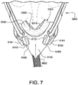
- Figs. 20A , 20B , and 20C show alternative examples of patient interfaces.
- the patient interfaces 7000, 8000, 9000 include a frame and seal-forming structure including a foam and/or a textile material.
- at least a portion of the headgear may include a textile material that may be integrated or otherwise provide an interface with the frame/seal-forming structure.
- the upper portion of the seal-forming structure 6200 includes a nasal cushion 6300 (also referred to as a nasal seal or cradle seal) structured to seal around the lower portion of the patient's nose, e.g., around the ala and tip of the nose, and the lower portion of the seal-forming structure 6200 includes a mouth or cushion 6400 (also referred to as a mouth seal) structured to seal around the patient's mouth, e.g., at least along the sides of the mouth and along the lower lip/chin region.
- the nasal cushion 6300 and the mouth cushion 6400 cooperate to define, at least in part, the plenum chamber 6500.
- the periphery of the seal provided by the nasal cushion 6300 and the mouth cushion 6400 travels around the mouth from the left lower nose corner to the right lower nose corner via the chin cleft. From the left and right lower nose corners, the seal deviates sharply (e.g., nearly 90 degrees) to seal around the outer edges of underside of the patient's nose.
- the patient interface 6000 may be referred to as a "compact" patient interface or mask as the patient interface provides a compact form adapted to seal along a lower portion of the patient's nose, i.e., below the nasal bridge region of the patient's nose.
- the nasal cushion 6300 is provided or otherwise connected to an upper portion of the mouth cushion 6400 such that the nasal cushion 6300 extends along the upper part of a perimeter of the plenum chamber 6500 and the nasal cushion extends along the sides and lower part of the perimeter of the plenum chamber 6500.
- the nasal cushion 6300 includes a foam component 6305, e.g., formed by die cutting, including two separate openings therethrough.
- the thickness of the foam component is constant, e.g., 10-15 mm, e.g., 12 mm.
- thicker and thinner foam may be used and the thickness of the foam may not be uniform, e.g., thickness may vary in one or more regions of the nasal cushion.
- the foam component of the nasal cushion may be compression cut, e.g., to provide more rounded and tapered edges and/or openings, structured to more closely follow contours of the patient's nose.
- an airtight or impermeable textile membrane 6310 (e.g., elastic cloth membrane) is provided to the top surface or face contacting side of the foam component 6305.
- the outer perimeter of the membrane 6310 is joined to the foam component 6305 which allows the membrane 6310 to inflate and displace relative to the foam component 6305 during therapy.
- the membrane 6310 includes two separate openings 6315 that substantially align with the openings in the foam component 6305. The openings 6315 are unattached or free in order to allow treatment pressure to enter between the foam component 6305 and the membrane 6310, which allows the inflation of the membrane 6310 in use.
- the foam component and/or the membrane may include a single opening.
- one or both sides of the membrane 6310 i.e., face contacting side and/or non-face contacting side
- an impermeable surface e.g., impermeable silicone layer
- the non-face contacting side of the membrane 6310 may be laminated.
- Such arrangement provides a fabric pressure activated seal structured to inflate and minimise or prevent leaks with complex anthropometric regions of the patient's nose, e.g., concave and convex profiles of the patient's nose.
- the textile membrane or textile material of the nasal cushion is structured to inflate and displace relative to the foam component or textile material of the nasal cushion during therapy in order to provide a pressure activated seal against the patient's face in an area proximal the patient's nose.
- the membrane 6310 and foam component 6305 may function similar to a dual wall cushion made of silicone.
- the membrane 6310 is structured to inflate and sealing engage against the underside and sides of the patient's nose during therapy, e.g., seal around both nares. This arrangement allows the nose to remain sealed with the nasal cushion 6300 even when the nose is displaced or spaced from the foam component 6305.
- the inflation enables the nasal seal provided by the nasal cushion 6300 to behave dynamically such that any movements of the nose away from the face contacting side of the foam component 6305 can seal via the combination of the membrane 6310 and the treatment pressure causing the membrane 6310 to dynamically inflate.
- the seal may remain dynamic only within a certain range of movement as the membrane 6310 may only inflate to a certain extent.
- the membrane 6310 may only be provided to the top surface or face contacting side of the foam component 6305, such that exposed foam from the foam component 6305 is provided along the sides of the foam component 6305.
- Such arrangement provides foam surfaces at the corners of the patient's nose to help attain seal in these regions.
- the nasal cushion 6300 includes a bridge portion 6330 that extends or bridges across the upper portion of the mouth cushion 6400.
- the bridge portion 6330 is not required to form a seal as it is located entirely within the sealing periphery of the seal-forming structure 6200.
- the bridge portion 6330 may provide one or more of the following features: extra sealing surface to facilitate seal at the corners of the nose; seamless integration between the mouth and undernose sealing surfaces; support against the patient's face; and/or semantics for setup.
- the nasal cushion 6300 includes a V-shape (e.g., generally concave in shape) configured and arranged to capture or cradle the patient's nose and seal along the alar angle of the patient's nose.
- the nasal cushion 6300 may be shaped such that the nasal cushion 6300 will compress at different rates under the nose to achieve seal and comfort.
- the mouth cushion 6400 provides a seal that extends around the mouth from the left lower nose corner to the right lower nose corner via the chin cleft, and then blends seamlessly into the nasal cushion 6300.
- the mouth cushion 6400 includes a foam component 6405, e.g., formed by die cutting.
- the thickness of the foam component is constant, e.g., 10-15 mm, e.g., 12 mm.
- thicker and thinner foam may be used and the thickness of the foam may not be uniform, e.g., thickness may vary in one or more regions of the mouth cushion.
- the foam component of the mouth cushion may be compression cut, e.g., to provide more rounded and tapered edges, structured to more closely follow contours of the patient's face.
- the mouth cushion 6400 may vary in width around its perimeter to enhance sealing and comfort around the patient's mouth.
- the seal-forming structure provides a seal-forming surface, and may additionally provide a cushioning function.
- one or more portions of the seal-forming structure in accordance with the present technology may be constructed from a soft, flexible, resilient material such as silicone.
- the seal-forming structure may comprise a sealing flange and a support flange.
- the sealing flange comprises a relatively thin member with a thickness of less than about 1mm, for example about 0.25mm to about 0.45mm, that extends around the perimeter of the plenum chamber.
- Support flange may be relatively thicker than the sealing flange.
- the support flange is disposed between the sealing flange and the marginal edge of the plenum chamber, and extends at least part of the way around the perimeter.
- the support flange is or includes a spring-like element and functions to support the sealing flange from buckling in use. In use the sealing flange can readily respond to system pressure in the plenum chamber acting on its underside to urge it into tight sealing engagement with the face.
- the seal-forming portion of the non-invasive patient interface may comprise a pair of nasal puffs, or nasal pillows, each nasal puff or nasal pillow being constructed and arranged to form a seal with a respective naris of the nose of a patient.
- Nasal pillows in accordance with an aspect of the present technology include: a frusto-cone, at least a portion of which forms a seal on an underside of the patient's nose, a stalk, a flexible region on the underside of the frusto-cone and connecting the frusto-cone to the stalk.
- the structure to which the nasal pillow of the present technology is connected includes a flexible region adjacent the base of the stalk.
- the flexible regions can act in concert to facilitate a universal joint structure that is accommodating of relative movement both displacement and angular of the frusto-cone and the structure to which the nasal pillow is connected.
- the frusto-cone may be axially displaced towards the structure to which the stalk is connected.
- the non-invasive patient interface comprises a seal-forming portion that forms a seal in use on an upper lip region (that is, the lip superior) of the patient's face.
- the non-invasive patient interface comprises a seal-forming portion that forms a seal in use on a chin-region of the patient's face.
- a seal-forming structure is configured to correspond to a particular size of head and/or shape of face.
- a seal-forming structure is suitable for a large sized head, but not a small sized head.
- a form of seal-forming structure is suitable for a small sized head, but not a large sized head.
- the three-dimensional shape of the seal-forming structure 6200 around the patient's nose and mouth is provided by the support of the more rigid textile frame 6100. That is, the textile frame 6100 includes a predetermined three-dimensional structure, shape, or geometry which provides plenum chamber 6500 and edges or surfaces configured and arranged to support and shape the seal-forming structure 6200 into a pre-formed three-dimensional shape adapted to closely follow and seal along the contours of the patient's nose and mouth. In an example, the predetermined three-dimensional shape of the frame 6100 is maintained throughout the patient's respiratory cycle.
- edges of the frame 6100 provide cushion support surfaces structured and arranged to support and hold the nasal cushion 6300 and the mouth cushion 6400 in predetermined shapes to closely match contours of the patient's nose and mouth, i.e., frame geometry imparts a predetermined three-dimensional shape to the nasal and mouth cushions 6300, 6400 when the nasal and mouth cushions are attached to the cushion support surfaces of the frame 6100 so as to adjust the shape of the nasal and mouth cushions to match a curvature of the patient's nose and mouth.
- the cushion support surfaces may include different curvatures in different regions along its perimeter to impart different shapes or curvatures in different regions of the nasal and mouth cushions.
- the frame 6100 has concave, exterior surfaces which are configured to closely follow or match the contour of an adjacent seal-forming structure when compressed. This arrangement helps improve the stability of the patient interface as it does not need to overcome external geometries trying to unseat the patient interface from the patient's face.
- frame 6100 is constructed or made of an airtight or impermeable textile material.
- one or both sides of the textile material i.e., internal and/or external surfaces of the frame
- an impermeable surface e.g., impermeable silicone layer or membrane imbedded in textile material
- Such arrangement provides an impermeable structure for the plenum chamber 6500.
- the frame 6100 is formed by cutting a flat piece of textile material into a particular geometry so that when bent/folded and joined creates a 3-dimensional shape.
- the frame may be formed by thermoforming textile material into the desired 3-dimensional shape to suit the patient's face. Other methods of fabric shaping may also be applicable.
- the frame 6100 may include a spacer fabric having a three-dimensional knitted fabric structure.
- an internal structural skeleton frame may be added to the textile frame to provide further support for the nasal and/or mouth cushion, e.g., create a surface for the nasal cushion to rest against.
- the skeleton frame may be permanently attached on the inside of the textile frame.
- all internal structural support may be incorporated into the thermoforming process.
- the textile material of the frame includes a structure of a textile scaffold, mesh, netting or webbing.
- Figs. 14 to 19 provide exemplary steps for forming the three-dimensional shape of the textile frame 6100 according to an example of the present technology.
- Fig. 14 shows a textile or fabric material 6105 (with an impermeable surface) that is cut or otherwise formed into a predetermined flat shape that provides the necessary material to construct the three-dimensional frame 6100.
- Fig. 15 shows the fabric material 6105 of Fig. 14 folded in a particular manner into the three-dimensional shape of the frame 6100.
- Fig. 16 shows the folded, fabric material 6105 of Fig. 15 joined at the front edge 6110 and the short sides 6115 of the chin fold to hold the three-dimensional shape of the frame 6100.
- Fig. 14 shows a textile or fabric material 6105 (with an impermeable surface) that is cut or otherwise formed into a predetermined flat shape that provides the necessary material to construct the three-dimensional frame 6100.
- Fig. 15 shows the fabric material 6105 of Fig. 14 folded in a particular manner into the three-dimensional shape of the
- the front joint 6110 acts as a central spine for the frame 6100.
- Fig. 17 shows the joined, fabric material 6105 of Fig. 16 which produces an internal, three-dimensional shape of the plenum chamber 6500 provided by the frame 6100.
- Figs. 18 and 19 shows the fabric, three-dimensional frame 6100 of Fig. 17 in position on a patient's face, which shows the frame conforming to the sides and lower portion of the mouth.
- the nasal cushion 6300 is provided to an upper portion of the frame 6100 to form the upper part of the patient interface, and mouth cushion 6400 is provided to the frame 6100 and joined with the nasal cushion 6300 to complete the seal-forming structure 6200.
- the air delivery tube 6600 e.g., straight tube
- the air delivery tube may include a swivel at one or both ends.
- the plenum chamber 6500 has a perimeter that is shaped to be complementary to the surface contour of the face of an average person in the region where a seal will form in use. In use, a marginal edge of the plenum chamber 6500 is positioned in close proximity to an adjacent surface of the face. Actual contact with the face is provided by the seal-forming structure 6200. The seal-forming structure 6200 may extend in use about the entire perimeter of the plenum chamber 6500.
- the seal-forming structure 6200 of the patient interface 6000 of the present technology may be held in sealing position in use by the headgear 6800.
- the headgear 6800 includes a pair of upper side straps 6802 and a pair of lower side straps 6804 connected to a circular crown strap 6806 that encapsulates the crown of the patient's head.
- the upper side straps 6802 connect to respective upper headgear connectors 6130 of the frame 6100 and the lower side straps 6804 connect to respective lower headgear connectors 6150 of the frame 6100, e.g., via respective headgear clips 6160, 6161.
- the side straps 6802, 6804 may include an adjustable hook and loop (Velcro TM ) connection mechanism, e.g., Velcro TM -like hook tabs, to facilitate connection and/or adjustment.
- Velcro TM adjustable hook and loop
- the upper and lower headgear connectors 6130, 6150 provide a 4-point connection to the headgear 6800.
- each of the upper side straps 6802 is arranged to extend between the patient's ear and eye and provide an upper force vector that extends upwardly at an angle with respect to the Frankfort horizontal line.
- Each of the lower side straps 6804 is arranged to extend below the patient's ear and provide a lower force vector that extends generally parallel to the Frankfort horizontal line. Such arrangement ensures that suitable force vectors are provided to seal the seal-forming structure 6200 with both the patient's nose and mouth.
- the two upper force vectors strategically pass directly over the corners of the nose in order to maximise foam compression in this region for a robust seal.
- the two upper vectors are attached to the front portion of the frame, which enables the rear of the upper portion of the frame (where the foam seal is attached) to splay out and conform to the patient's face shape, e.g., conform to region incorporating seal at the corner of the nose.
- the two lower force vectors are positioned towards the rear of the frame directly above the foam seal. This enables the headgear to directly apply force onto the foam seal. This is the widest part of the patient interface which correlates to the largest force pulling the patient interface away from the patient's face.
- the upper force vectors will draw the nasal cushion 6300 up and into sealing engagement with the patient's nose and the lower force vectors will draw the mouth cushion 6400 back and into sealing engagement around the patient's mouth.
- the resultant force vector when headgear tension is applied allows for effective sealing at both the nasal cushion 6300 and the mouth cushion 6400.
- each of the upper and lower headgear connectors 6130, 6150 of the frame 6100 includes a headgear connection point in the form of a magnetic connector 6155 (e.g., encased magnet) structured to locate and connect to a magnet 6162 associated with the respective headgear clip 6160, 6161 provided to a respective strap of the headgear 6800, e.g., see Figs. 4 , 5 , 6 , 7 , and 9 .
- the upper and lower headgear connectors 6130, 6150 may be connected with headgear straps of the headgear in other suitable manners.
- a positioning and stabilising structure is provided that is configured in a manner consistent with being worn by a patient while sleeping.
- the positioning and stabilising structure has a low profile, or cross-sectional thickness, to reduce the perceived or actual bulk of the apparatus.
- the positioning and stabilising structure comprises at least one strap having a rectangular cross-section. In one example the positioning and stabilising structure comprises at least one flat strap.
- a positioning and stabilising structure comprises a strap constructed from a laminate of a fabric patient-contacting layer, a foam inner layer and a fabric outer layer.
- the foam is porous to allow moisture, (e.g., sweat), to pass through the strap.
- the fabric outer layer comprises loop material to engage with a hook material portion.
- a positioning and stabilising structure comprises a strap that is extensible, e.g. resiliently extensible.
- the strap may be configured in use to be in tension, and to direct a force to draw a cushion into sealing contact with a portion of a patient's face.
- the strap may be configured as a tie.
- a positioning and stabilising structure comprises a strap that is bendable and e.g. non-rigid.
- a positioning and stabilizing structure provides a retaining force configured to correspond to a particular size of head and/or shape of face.
- one form of positioning and stabilizing structure provides a retaining force suitable for a large sized head, but not a small sized head.
- a form of positioning and stabilizing structure provides a retaining force suitable for a small sized head, but not a large sized head.
- the patient interface 6000 includes a vent 6900 constructed and arranged to allow for the washout of exhaled gases, e.g. carbon dioxide.
- exhaled gases e.g. carbon dioxide.
- vent 6900 in accordance with the present technology comprises a plurality of holes, for example, about 20 to about 80 holes, or about 40 to about 60 holes, or about 45 to about 55 holes.
- the vent 6900 may be located in the plenum chamber 6500, e.g., provided to the frame 6100.
- the vent 6900 is located in a decoupling structure, e.g., a swivel.
- the patient interface includes at least one decoupling structure, for example, a swivel or a ball and socket.
- the patient interface includes a connection port that allows for connection to the air circuit 4170.
- the patient interface includes a forehead support.
- the patient interface includes an anti-asphyxia valve.
- a patient interface includes one or more ports that allow access to the volume within the plenum chamber. In one form this allows a clinician to supply supplemental oxygen. In one form, this allows for the direct measurement of a property of gases within the plenum chamber, such as the pressure.
- Air In certain forms of the present technology, air may be taken to mean atmospheric air, and in other forms of the present technology air may be taken to mean some other combination of breathable gases, e.g. atmospheric air enriched with oxygen.
- ambient In certain forms of the present technology, the term ambient will be taken to mean (i) external of the treatment system or patient, and (ii) immediately surrounding the treatment system or patient.
- ambient humidity with respect to a humidifier may be the humidity of air immediately surrounding the humidifier, e.g. the humidity in the room where a patient is sleeping. Such ambient humidity may be different to the humidity outside the room where a patient is sleeping.
- ambient pressure may be the pressure immediately surrounding or external to the body.
- ambient noise may be considered to be the background noise level in the room where a patient is located, other than for example, noise generated by an RPT device or emanating from a mask or patient interface.
- Ambient noise may be generated by sources outside the room.
- APAP therapy in which the treatment pressure is automatically adjustable, e.g. from breath to breath, between minimum and maximum limits, depending on the presence or absence of indications of SDB events.
- Continuous Positive Airway Pressure (CPAP) therapy Respiratory pressure therapy in which the treatment pressure is approximately constant through a respiratory cycle of a patient.
- the pressure at the entrance to the airways will be slightly higher during exhalation, and slightly lower during inhalation.
- the pressure will vary between different respiratory cycles of the patient, for example, being increased in response to detection of indications of partial upper airway obstruction, and decreased in the absence of indications of partial upper airway obstruction.
- Flow rate The volume (or mass) of air delivered per unit time. Flow rate may refer to an instantaneous quantity. In some cases, a reference to flow rate will be a reference to a scalar quantity, namely a quantity having magnitude only. In other cases, a reference to flow rate will be a reference to a vector quantity, namely a quantity having both magnitude and direction. Flow rate may be given the symbol Q . 'Flow rate' is sometimes shortened to simply 'flow'.
- a flow rate may be nominally positive for the inspiratory portion of a breathing cycle of a patient, and hence negative for the expiratory portion of the breathing cycle of a patient.
- Total flow rate, Qt is the flow rate of air leaving the RPT device.
- Vent flow rate, Qv is the flow rate of air leaving a vent to allow washout of exhaled gases.
- Leak flow rate, Ql is the flow rate of leak from a patient interface system or elsewhere.
- Respiratory flow rate, Qr is the flow rate of air that is received into the patient's respiratory system.
- Leak The word leak will be taken to be an unintended flow of air. In one example, leak may occur as the result of an incomplete seal between a mask and a patient's face. In another example leak may occur in a swivel elbow to the ambient.
- Conducted noise in the present document refers to noise which is carried to the patient by the pneumatic path, such as the air circuit and the patient interface as well as the air therein.
- conducted noise may be quantified by measuring sound pressure levels at the end of an air circuit.
- Radiated noise in the present document refers to noise which is carried to the patient by the ambient air.
- radiated noise may be quantified by measuring sound power/pressure levels of the object in question according to ISO 3744.
- Vent noise in the present document refers to noise which is generated by the flow of air through any vents such as vent holes of the patient interface.
- Patient A person, whether or not they are suffering from a respiratory disease.
- Pressure Force per unit area. Pressure may be expressed in a range of units, including cmH 2 O, g-f/cm 2 and hectopascal. 1 cmH 2 O is equal to 1 g-f/cm 2 and is approximately 0.98 hectopascal. In this specification, unless otherwise stated, pressure is given in units of cmH 2 O.
- the pressure in the patient interface is given the symbol Pm, while the treatment pressure, which represents a target value to be achieved by the mask pressure Pm at the current instant of time, is given the symbol Pt.
- Respiratory Pressure Therapy The application of a supply of air to an entrance to the airways at a treatment pressure that is typically positive with respect to atmosphere.
- Ventilator A mechanical device that provides pressure support to a patient to perform some or all of the work of breathing.
- Silicone or Silicone Elastomer A synthetic rubber.
- a reference to silicone is a reference to liquid silicone rubber (LSR) or a compression moulded silicone rubber (CMSR).
- LSR liquid silicone rubber
- CMSR compression moulded silicone rubber
- SILASTIC included in the range of products sold under this trademark
- Another manufacturer of LSR is Wacker.
- an exemplary form of LSR has a Shore A (or Type A) indentation hardness in the range of about 35 to about 45 as measured using ASTM D2240.
- Polycarbonate a typically transparent thermoplastic polymer of Bisphenol-A Carbonate.
- Resilience Ability of a material to absorb energy when deformed elastically and to release the energy upon unloading.
- Hardness The ability of a material per se to resist deformation (e.g. described by a Young's Modulus, or an indentation hardness scale measured on a standardised sample size).
- Stiffness (or rigidity) of a structure or component The ability of the structure or component to resist deformation in response to an applied load.
- the load may be a force or a moment, e.g. compression, tension, bending or torsion.
- the structure or component may offer different resistances in different directions.
- an I-beam may comprise a different bending stiffness (resistance to a bending load) in a first direction in comparison to a second, orthogonal direction.
- a structure or component may be floppy in a first direction and rigid in a second direction.
- an apnea is said to have occurred when flow falls below a predetermined threshold for a duration, e.g. 10 seconds.
- An obstructive apnea will be said to have occurred when, despite patient effort, some obstruction of the airway does not allow air to flow.
- a central apnea will be said to have occurred when an apnea is detected that is due to a reduction in breathing effort, or the absence of breathing effort, despite the airway being patent.
- a mixed apnea occurs when a reduction or absence of breathing effort coincides with an obstructed airway.
- Breathing rate The rate of spontaneous respiration of a patient, usually measured in breaths per minute.
- Duty cycle The ratio of inhalation time, Ti to total breath time, Ttot.
- Effort The work done by a spontaneously breathing person attempting to breathe.
- Expiratory portion of a breathing cycle The period from the start of expiratory flow to the start of inspiratory flow.
- Flow limitation will be taken to be the state of affairs in a patient's respiration where an increase in effort by the patient does not give rise to a corresponding increase in flow. Where flow limitation occurs during an inspiratory portion of the breathing cycle it may be described as inspiratory flow limitation. Where flow limitation occurs during an expiratory portion of the breathing cycle it may be described as expiratory flow limitation.
- hypopnea is taken to be a reduction in flow, but not a cessation of flow.
- a hypopnea may be said to have occurred when there is a reduction in flow below a threshold rate for a duration.
- a central hypopnea will be said to have occurred when a hypopnea is detected that is due to a reduction in breathing effort.
- hypopneas either of the following may be regarded as being hypopneas:
- Hyperpnea An increase in flow to a level higher than normal.
- Inspiratory portion of a breathing cycle The period from the start of inspiratory flow to the start of expiratory flow will be taken to be the inspiratory portion of a breathing cycle.
- Patency The degree of the airway being open, or the extent to which the airway is open. A patent airway is open. Airway patency may be quantified, for example with a value of one (1) being patent, and a value of zero (0), being closed (obstructed).
- PEEP Positive End-Expiratory Pressure
- Peak flow rate (Qpeak) The maximum value of flow rate during the inspiratory portion of the respiratory flow waveform.
- Vt Tidal volume
- Total Time (Ttot) The total duration between the start of one inspiratory portion of a respiratory flow rate waveform and the start of the following inspiratory portion of the respiratory flow rate waveform.
- Typical recent ventilation The value of ventilation around which recent values of ventilation Vent over some predetermined timescale tend to cluster, that is, a measure of the central tendency of the recent values of ventilation.
- Upper airway obstruction includes both partial and total upper airway obstruction. This may be associated with a state of flow limitation, in which the flow rate increases only slightly or may even decrease as the pressure difference across the upper airway increases (Starling resistor behaviour).
- Ventilation A measure of a rate of gas being exchanged by the patient's respiratory system. Measures of ventilation may include one or both of inspiratory and expiratory flow, per unit time. When expressed as a volume per minute, this quantity is often referred to as "minute ventilation”. Minute ventilation is sometimes given simply as a volume, understood to be the volume per minute.
- Adaptive Servo-Ventilator A servo-ventilator that has a changeable, rather than fixed target ventilation.
- the changeable target ventilation may be learned from some characteristic of the patient, for example, a respiratory characteristic of the patient.
- a parameter of a ventilator that establishes the minimum breathing rate (typically in number of breaths per minute) that the ventilator will deliver to the patient, if not triggered by spontaneous respiratory effort.
- Expiratory positive airway pressure a base pressure, to which a pressure varying within the breath is added to produce the desired mask pressure which the ventilator will attempt to achieve at a given time.
- Inspiratory positive airway pressure (IPAP): Maximum desired mask pressure which the ventilator will attempt to achieve during the inspiratory portion of the breath.
- Servo-ventilator A ventilator that measures patient ventilation, has a target ventilation, and which adjusts the level of pressure support to bring the patient ventilation towards the target ventilation.
- Spontaneous / Timed A mode of a ventilator or other device that attempts to detect the initiation of a breath of a spontaneously breathing patient. If however, the device is unable to detect a breath within a predetermined period of time, the device will automatically initiate delivery of the breath.
- Triggered When a ventilator delivers a breath of air to a spontaneously breathing patient, it is said to be triggered to do so at the initiation of the respiratory portion of the breathing cycle by the patient's efforts.
- the typical recent ventilation Vtyp is the value around which recent measures of ventilation over some predetermined timescale tend to cluster.
- a measure of the central tendency of the measures of ventilation over recent history may be a suitable value of a typical recent ventilation.
- Ala the external outer wall or "wing" of each nostril (plural: alar)
- Alare The most lateral point on the nasal ala.
- Alar curvature (or alar crest) point The most posterior point in the curved base line of each ala, found in the crease formed by the union of the ala with the cheek.
- Auricle The whole external visible part of the ear.
- (nose) Bony framework The bony framework of the nose comprises the nasal bones, the frontal process of the maxillae and the nasal part of the frontal bone.
- (nose) Cartilaginous framework The cartilaginous framework of the nose comprises the septal, lateral, major and minor cartilages.
- Columella the strip of skin that separates the nares and which runs from the pronasale to the upper lip.
- Columella angle The angle between the line drawn through the midpoint of the nostril aperture and a line drawn perpendicular to the Frankfurt horizontal while intersecting subnasale.
- Frankfort horizontal plane A line extending from the most inferior point of the orbital margin to the left tragion.
- the tragion is the deepest point in the notch superior to the tragus of the auricle.
- Glabella Located on the soft tissue, the most prominent point in the midsagittal plane of the forehead.
- Lateral nasal cartilage A generally triangular plate of cartilage. Its superior margin is attached to the nasal bone and frontal process of the maxilla, and its inferior margin is connected to the greater alar cartilage.
- Greater alar cartilage A plate of cartilage lying below the lateral nasal cartilage. It is curved around the anterior part of the naris. Its posterior end is connected to the frontal process of the maxilla by a tough fibrous membrane containing three or four minor cartilages of the ala.
- Nares Nostrils: Approximately ellipsoidal apertures forming the entrance to the nasal cavity.
- the singular form of nares is naris (nostril). The nares are separated by the nasal septum.
- Naso-labial sulcus or Naso-labialfold The skin fold or groove that runs from each side of the nose to the corners of the mouth, separating the cheeks from the upper lip.
- Naso-labial angle The angle between the columella and the upper lip, while intersecting subnasale.
- Otobasion inferior The lowest point of attachment of the auricle to the skin of the face.
- Otobasion superior The highest point of attachment of the auricle to the skin of the face.
- Pronasale the most protruded point or tip of the nose, which can be identified in lateral view of the rest of the portion of the head.
- Philtrum the midline groove that runs from lower border of the nasal septum to the top of the lip in the upper lip region.
- Pogonion Located on the soft tissue, the most anterior midpoint of the chin.
- nasal Ridge The nasal ridge is the midline prominence of the nose, extending from the Sellion to the Pronasale.
- Sagittal plane A vertical plane that passes from anterior (front) to posterior (rear) dividing the body into right and left halves.
- Septal cartilage (nasal): The nasal septal cartilage forms part of the septum and divides the front part of the nasal cavity.
- Subalare The point at the lower margin of the alar base, where the alar base joins with the skin of the superior (upper) lip.
- Subnasal point Located on the soft tissue, the point at which the columella merges with the upper lip in the midsagittal plane.
- Frontal bone The frontal bone includes a large vertical portion, the squama frontalis, corresponding to the region known as the forehead.
- Mandible forms the lower jaw.
- the mental protuberance is the bony protuberance of the jaw that forms the chin.
- Maxilla The maxilla forms the upper jaw and is located above the mandible and below the orbits. The frontal process of the maxilla projects upwards by the side of the nose, and forms part of its lateral boundary.
- Nasal bones The nasal bones are two small oblong bones, varying in size and form in different individuals; they are placed side by side at the middle and upper part of the face, and form, by their junction, the "bridge" of the nose.
- Nasion The intersection of the frontal bone and the two nasal bones, a depressed area directly between the eyes and superior to the bridge of the nose.
- Occipital bone The occipital bone is situated at the back and lower part of the cranium. It includes an oval aperture, the foramen magnum, through which the cranial cavity communicates with the vertebral canal.
- the curved plate behind the foramen magnum is the squama occipitalis.
- Orbit The bony cavity in the skull to contain the eyeball.
- the parietal bones are the bones that, when joined together, form the roof and sides of the cranium.
- Temporal bones The temporal bones are situated on the bases and sides of the skull, and support that part of the face known as the temple.
- Zygomatic bones The face includes two zygomatic bones, located in the upper and lateral parts of the face and forming the prominence of the cheek.
- Diaphragm A sheet of muscle that extends across the bottom of the rib cage. The diaphragm separates the thoracic cavity, containing the heart, lungs and ribs, from the abdominal cavity. As the diaphragm contracts the volume of the thoracic cavity increases and air is drawn into the lungs.
- Larynx The larynx, or voice box houses the vocal folds and connects the inferior part of the pharynx (hypopharynx) with the trachea.
- Lungs The organs of respiration in humans.
- the conducting zone of the lungs contains the trachea, the bronchi, the bronchioles, and the terminal bronchioles.
- the respiratory zone contains the respiratory bronchioles, the alveolar ducts, and the alveoli.
- Nasal cavity The nasal cavity (or nasal fossa) is a large air filled space above and behind the nose in the middle of the face.
- the nasal cavity is divided in two by a vertical fin called the nasal septum.
- On the sides of the nasal cavity are three horizontal outgrowths called nasal conchae (singular "concha") or turbinates.
- nasal conchae singular "concha”
- turbinates To the front of the nasal cavity is the nose, while the back blends, via the choanae, into the nasopharynx.
- Pharynx The part of the throat situated immediately inferior to (below) the nasal cavity, and superior to the oesophagus and larynx.
- the pharynx is conventionally divided into three sections: the nasopharynx (epipharynx) (the nasal part of the pharynx), the oropharynx (mesopharynx) (the oral part of the pharynx), and the laryngopharynx (hypopharynx).
- Anti-asphyxia valve The component or sub-assembly of a mask system that, by opening to atmosphere in a failsafe manner, reduces the risk of excessive CO 2 rebreathing by a patient.
- an elbow is an example of a structure that directs an axis of flow of air travelling therethrough to change direction through an angle.
- the angle may be approximately 90 degrees.
- the angle may be more, or less than 90 degrees.
- the elbow may have an approximately circular cross-section.
- the elbow may have an oval or a rectangular cross-section.
- an elbow may be rotatable with respect to a mating component, e.g. about 360 degrees.
- an elbow may be removable from a mating component, e.g. via a snap connection.
- an elbow may be assembled to a mating component via a one-time snap during manufacture, but not removable by a patient.
- Frame will be taken to mean a mask structure that bears the load of tension between two or more points of connection with a headgear.
- a mask frame may be a non-airtight load bearing structure in the mask. However, some forms of mask frame may also be air-tight.
- Headgear will be taken to mean a form of positioning and stabilizing structure designed for use on a head.
- the headgear may comprise a collection of one or more struts, ties and stiffeners configured to locate and retain a patient interface in position on a patient's face for delivery of respiratory therapy.
- Some ties are formed of a soft, flexible, elastic material such as a laminated composite of foam and fabric.
- Membrane will be taken to mean a typically thin element that has, preferably, substantially no resistance to bending, but has resistance to being stretched.
- Plenum chamber a mask plenum chamber will be taken to mean a portion of a patient interface having walls at least partially enclosing a volume of space, the volume having air therein pressurised above atmospheric pressure in use.
- a shell may form part of the walls of a mask plenum chamber.
- Seal May be a noun form ("a seal”) which refers to a structure, or a verb form ("to seal”) which refers to the effect.
- a seal noun form
- to seal to seal
- Two elements may be constructed and/or arranged to 'seal' or to effect 'sealing' therebetween without requiring a separate 'seal' element per se.
- a shell will be taken to mean a curved, relatively thin structure having bending, tensile and compressive stiffness.
- a curved structural wall of a mask may be a shell.
- a shell may be faceted.
- a shell may be airtight.
- a shell may not be airtight.
- a stiffener will be taken to mean a structural component designed to increase the bending resistance of another component in at least one direction.
- a strut will be taken to be a structural component designed to increase the compression resistance of another component in at least one direction.
- Swivel A subassembly of components configured to rotate about a common axis, preferably independently, preferably under low torque.
- the swivel may be constructed to rotate through an angle of at least 360 degrees.
- the swivel may be constructed to rotate through an angle less than 360 degrees.
- the sub-assembly of components preferably comprises a matched pair of cylindrical conduits. There may be little or no leak flow of air from the swivel in use.
- Tie A structure designed to resist tension.
- Vent (noun): A structure that allows a flow of air from an interior of the mask, or conduit, to ambient air for clinically effective washout of exhaled gases.
- a clinically effective washout may involve a flow rate of about 10 litres per minute to about 100 litres per minute, depending on the mask design and treatment pressure.
- Products in accordance with the present technology may comprise one or more three-dimensional mechanical structures, for example a mask cushion or an impeller.
- the three-dimensional structures may be bounded by two-dimensional surfaces. These surfaces may be distinguished using a label to describe an associated surface orientation, location, function, or some other characteristic.
- a structure may comprise one or more of an anterior surface, a posterior surface, an interior surface and an exterior surface.
- a cushion structure may comprise a face-contacting (e.g. outer) surface, and a separate non-face-contacting (e.g. underside or inner) surface.
- a structure may comprise a first surface and a second surface.
- Fig. 3B to Fig. 3F illustrate examples of cross-sections at point p on a surface, and the resulting plane curves.
- Figs. 3B to 3F also illustrate an outward normal vector at p.
- the outward normal vector at p points away from the surface.
- the curvature of a plane curve at p may be described as having a sign (e.g. positive, negative) and a magnitude (e.g. 1/radius of a circle that just touches the curve at p ).
- Negative curvature If the curve at p turns away from the outward normal, the curvature in that direction at that point will be taken to be negative (if the imaginary small person leaves the point p they must walk downhill). See Fig. 3E (relatively small negative curvature compared to Fig. 3F) and Fig. 3F (relatively large negative curvature compared to Fig. 3E ). Such curves are often referred to as convex.
- a description of the shape at a given point on a two-dimensional surface in accordance with the present technology may include multiple normal cross-sections.
- the multiple cross-sections may cut the surface in a plane that includes the outward normal (a "normal plane"), and each cross-section may be taken in a different direction.
- Each cross-section results in a plane curve with a corresponding curvature.
- the different curvatures at that point may have the same sign, or a different sign.
- Each of the curvatures at that point has a magnitude, e.g. relatively small.
- the plane curves in Figs. 3B to 3F could be examples of such multiple cross-sections at a particular point.
- Principal curvatures and directions The directions of the normal planes where the curvature of the curve takes its maximum and minimum values are called the principal directions.
- the maximum curvature occurs in Fig. 3B
- the minimum occurs in Fig. 3F
- Fig. 3B and Fig. 3F are cross sections in the principal directions.
- the principal curvatures at p are the curvatures in the principal directions.
- Region of a surface A connected set of points on a surface.
- the set of points in a region may have similar characteristics, e.g. curvatures or signs.
- Saddle region A region where at each point, the principal curvatures have opposite signs, that is, one is positive, and the other is negative (depending on the direction to which the imaginary person turns, they may walk uphill or downhill).
- Dome region A region where at each point the principal curvatures have the same sign, e.g. both positive (a "concave dome”) or both negative (a “convex dome”).
- Cylindrical region A region where one principal curvature is zero (or, for example, zero within manufacturing tolerances) and the other principal curvature is non-zero.
- Planar region A region of a surface where both of the principal curvatures are zero (or, for example, zero within manufacturing tolerances).
- Edge of a surface A boundary or limit of a surface or region.
- 'path' will be taken to mean a path in the mathematical - topological sense, e.g. a continuous space curve from f (0) to f ( 1) on a surface.
- a 'path' may be described as a route or course, including e.g. a set of points on a surface. (The path for the imaginary person is where they walk on the surface, and is analogous to a garden path).
- Path length In certain forms of the present technology, 'path length' will be taken to the distance along the surface from f (0) to f (1), that is, the distance along the path on the surface. There may be more than one path between two points on a surface and such paths may have different path lengths. (The path length for the imaginary person would be the distance they have to walk on the surface along the path).
- the straight-line distance is the distance between two points on a surface, but without regard to the surface. On planar regions, there would be a path on the surface having the same path length as the straight-line distance between two points on the surface. On non-planar surfaces, there may be no paths having the same path length as the straight-line distance between two points. (For the imaginary person, the straight-line distance would correspond to the distance 'as the crow flies'.)
- a space curve does not necessarily lie in any particular plane.
- a space curve may be considered to be a one-dimensional piece of three-dimensional space.
- An imaginary person walking on a strand of the DNA helix walks along a space curve.
- a typical human left ear comprises a left-hand helix, see Fig. 3P .
- a typical human right ear comprises a right-hand helix, see Fig. 3Q.
- Fig. 3R shows a right-hand helix.
- the edge of a structure e.g. the edge of a membrane or impeller, may follow a space curve.
- a space curve may be described by a curvature and a torsion at each point on the space curve. Torsion is a measure of how the curve turns out of a plane. Torsion has a sign and a magnitude. The torsion at a point on a space curve may be characterised with reference to the tangent, normal and binormal vectors at that point.
- Tangent unit vector (or unit tangent vector): For each point on a curve, a vector at the point specifies a direction from that point, as well as a magnitude. A tangent unit vector is a unit vector pointing in the same direction as the curve at that point. If an imaginary person were flying along the curve and fell off her vehicle at a particular point, the direction of the tangent vector is the direction she would be travelling.
- Unit normal vector As the imaginary person moves along the curve, this tangent vector itself changes.
- the unit vector pointing in the same direction that the tangent vector is changing is called the unit principal normal vector. It is perpendicular to the tangent vector.
- Binormal unit vector The binormal unit vector is perpendicular to both the tangent vector and the principal normal vector. Its direction may be determined by a right-hand rule (see e.g. Fig. 3O ), or alternatively by a left-hand rule ( Fig. 3N ).
- Osculating plane The plane containing the unit tangent vector and the unit principal normal vector. See Figures 3N and 3O .
- Torsion of a space curve is the magnitude of the rate of change of the binormal unit vector at that point. It measures how much the curve deviates from the osculating plane.
- a space curve which lies in a plane has zero torsion.
- a space curve which deviates a relatively small amount from the osculating plane will have a relatively small magnitude of torsion (e.g. a gently sloping helical path).
- a space curve which deviates a relatively large amount from the osculating plane will have a relatively large magnitude of torsion (e.g. a steeply sloping helical path).
- T2>T1 the magnitude of the torsion near the top coils of the helix of Fig. 3R is greater than the magnitude of the torsion of the bottom coils of the helix of Fig. 3R
- a space curve turning towards the direction of the right-hand binormal may be considered as having a right-hand positive torsion (e.g. a right-hand helix as shown in Fig. 3R ).
- a space curve turning away from the direction of the right-hand binormal may be considered as having a right-hand negative torsion (e.g. a left-hand helix).
- a space curve turning towards the direction of the left-hand binormal may be considered as having a left-hand positive torsion (e.g. a left-hand helix).
- left-hand positive is equivalent to right-hand negative. See Fig. 3S .
- a surface may have a one-dimensional hole, e.g. a hole bounded by a plane curve or by a space curve.
- Thin structures e.g. a membrane
- Thin structures with a hole, may be described as having a one-dimensional hole. See for example the one dimensional hole in the surface of structure shown in Fig. 31, bounded by the plane curve 301D.
- a structure may have a two-dimensional hole, e.g. a hole bounded by a surface.
- a hole bounded by a surface For example, an inflatable tyre has a two dimensional hole bounded by the inside surface of the tyre.
- a bladder with a cavity for air or gel could have a two-dimensional hole. See for example the cushion of Fig. 3L and the example cross-section there through in Fig. 3M .
- a conduit may comprise a one-dimension hole (e.g. at its entrance or at its exit), and a two-dimension hole bounded by the inside surface of the conduit. See also the two dimensional hole through the structure shown in Fig. 3K , bounded by surface 302D.
- any and all components herein described are understood to be capable of being manufactured and, as such, may be manufactured together or separately.
Abstract
Description
- This application claims the benefit of
U.S. Provisional Application No. 62/278,704, filed January 14, 2016 - The present technology relates to one or more of the detection, diagnosis, treatment, prevention and amelioration of respiratory-related disorders. The present technology also relates to medical devices or apparatus, and their use.
- The respiratory system of the body facilitates gas exchange. The nose and mouth form the entrance to the airways of a patient.
- The airways include a series of branching tubes, which become narrower, shorter and more numerous as they penetrate deeper into the lung. The prime function of the lung is gas exchange, allowing oxygen to move from the air into the venous blood and carbon dioxide to move out. The trachea divides into right and left main bronchi, which further divide eventually into terminal bronchioles. The bronchi make up the conducting airways, and do not take part in gas exchange. Further divisions of the airways lead to the respiratory bronchioles, and eventually to the alveoli. The alveolated region of the lung is where the gas exchange takes place, and is referred to as the respiratory zone. See " Respiratory Physiology", by John B. West, Lippincott Williams & Wilkins, 9th edition published 2011.
- A range of respiratory disorders exist. Certain disorders may be characterised by particular events, e.g. apneas, hypopneas, and hyperpneas.
- Obstructive Sleep Apnea (OSA), a form of Sleep Disordered Breathing (SDB), is characterized by events including occlusion or obstruction of the upper air passage during sleep. It results from a combination of an abnormally small upper airway and the normal loss of muscle tone in the region of the tongue, soft palate and posterior oropharyngeal wall during sleep. The condition causes the affected patient to stop breathing for periods typically of 30 to 120 seconds in duration, sometimes 200 to 300 times per night. It often causes excessive daytime somnolence, and it may cause cardiovascular disease and brain damage. The syndrome is a common disorder, particularly in middle aged overweight males, although a person affected may have no awareness of the problem. See
US Patent No. 4,944,310 (Sullivan ). - Cheyne-Stokes Respiration (CSR) is another form of sleep disordered breathing. CSR is a disorder of a patient's respiratory controller in which there are rhythmic alternating periods of waxing and waning ventilation known as CSR cycles. CSR is characterised by repetitive de-oxygenation and re-oxygenation of the arterial blood. It is possible that CSR is harmful because of the repetitive hypoxia. In some patients CSR is associated with repetitive arousal from sleep, which causes severe sleep disruption, increased sympathetic activity, and increased afterload. See
US Patent No. 6,532,959 (Berthon-Jones ). - Respiratory failure is an umbrella term for respiratory disorders in which the lungs are unable to inspire sufficient oxygen or exhale sufficient CO2 to meet the patient's needs. Respiratory failure may encompass some or all of the following disorders.
- A patient with respiratory insufficiency (a form of respiratory failure) may experience abnormal shortness of breath on exercise.
- Obesity Hyperventilation Syndrome (OHS) is defined as the combination of severe obesity and awake chronic hypercapnia, in the absence of other known causes for hypoventilation. Symptoms include dyspnea, morning headache and excessive daytime sleepiness.
- Chronic Obstructive Pulmonary Disease (COPD) encompasses any of a group of lower airway diseases that have certain characteristics in common. These include increased resistance to air movement, extended expiratory phase of respiration, and loss of the normal elasticity of the lung. Examples of COPD are emphysema and chronic bronchitis. COPD is caused by chronic tobacco smoking (primary risk factor), occupational exposures, air pollution and genetic factors. Symptoms include: dyspnea on exertion, chronic cough and sputum production.
- Neuromuscular Disease (NMD) is a broad term that encompasses many diseases and ailments that impair the functioning of the muscles either directly via intrinsic muscle pathology, or indirectly via nerve pathology. Some NMD patients are characterised by progressive muscular impairment leading to loss of ambulation, being wheelchair-bound, swallowing difficulties, respiratory muscle weakness and, eventually, death from respiratory failure. Neuromuscular disorders can be divided into rapidly progressive and slowly progressive: (i) Rapidly progressive disorders: Characterised by muscle impairment that worsens over months and results in death within a few years (e.g. Amyotrophic lateral sclerosis (ALS) and Duchenne muscular dystrophy (DMD) in teenagers); (ii) Variable or slowly progressive disorders: Characterised by muscle impairment that worsens over years and only mildly reduces life expectancy (e.g. Limb girdle, Facioscapulohumeral and Myotonic muscular dystrophy). Symptoms of respiratory failure in NMD include: increasing generalised weakness, dysphagia, dyspnea on exertion and at rest, fatigue, sleepiness, morning headache, and difficulties with concentration and mood changes.
- Chest wall disorders are a group of thoracic deformities that result in inefficient coupling between the respiratory muscles and the thoracic cage. The disorders are usually characterised by a restrictive defect and share the potential of long term hypercapnic respiratory failure. Scoliosis and/or kyphoscoliosis may cause severe respiratory failure. Symptoms of respiratory failure include: dyspnea on exertion, peripheral oedema, orthopnea, repeated chest infections, morning headaches, fatigue, poor sleep quality and loss of appetite.
- A range of therapies have been used to treat or ameliorate such conditions. Furthermore, otherwise healthy individuals may take advantage of such therapies to prevent respiratory disorders from arising. However, these have a number of shortcomings.
- Continuous Positive Airway Pressure (CPAP) therapy has been used to treat Obstructive Sleep Apnea (OSA). The mechanism of action is that continuous positive airway pressure acts as a pneumatic splint and may prevent upper airway occlusion, such as by pushing the soft palate and tongue forward and away from the posterior oropharyngeal wall. Treatment of OSA by CPAP therapy may be voluntary, and hence patients may elect not to comply with therapy if they find devices used to provide such therapy one or more of: uncomfortable, difficult to use, expensive and aesthetically unappealing.
- Non-invasive ventilation (NIV) provides ventilatory support to a patient through the upper airways to assist the patient breathing and/or maintain adequate oxygen levels in the body by doing some or all of the work of breathing. The ventilatory support is provided via a non-invasive patient interface. NIV has been used to treat CSR and respiratory failure, in forms such as OHS, COPD, NMD and Chest Wall disorders. In some forms, the comfort and effectiveness of these therapies may be improved.
- Invasive ventilation (IV) provides ventilatory support to patients that are no longer able to effectively breathe themselves and may be provided using a tracheostomy tube. In some forms, the comfort and effectiveness of these therapies may be improved.
- These therapies may be provided by a treatment system or device. Such systems and devices may also be used to diagnose a condition without treating it.
- A treatment system may comprise a Respiratory Pressure Therapy Device (RPT device), an air circuit, a humidifier, a patient interface, and data management.
- Another form of treatment system is a mandibular repositioning device.
- A patient interface may be used to interface respiratory equipment to its wearer, for example by providing a flow of air to an entrance to the airways. The flow of air may be provided via a mask to the nose and/or mouth, a tube to the mouth or a tracheostomy tube to the trachea of a patient. Depending upon the therapy to be applied, the patient interface may form a seal, e.g., with a region of the patient's face, to facilitate the delivery of gas at a pressure at sufficient variance with ambient pressure to effect therapy, e.g., at a positive pressure of about 10 cmH2O relative to ambient pressure. For other forms of therapy, such as the delivery of oxygen, the patient interface may not include a seal sufficient to facilitate delivery to the airways of a supply of gas at a positive pressure of about 10 cmH2O.
- Certain other mask systems may be functionally unsuitable for the present field. For example, purely ornamental masks may be unable to maintain a suitable pressure. Mask systems used for underwater swimming or diving may be configured to guard against ingress of water from an external higher pressure, but not to maintain air internally at a higher pressure than ambient.
- Certain masks may be clinically unfavourable for the present technology e.g. if they block airflow via the nose and only allow it via the mouth.
- Certain masks may be uncomfortable or impractical for the present technology if they require a patient to insert a portion of a mask structure in their mouth to create and maintain a seal via their lips.
- Certain masks may be impractical for use while sleeping, e.g. for sleeping while lying on one's side in bed with a head on a pillow.
- The design of a patient interface presents a number of challenges. The face has a complex three-dimensional shape. The size and shape of noses and heads varies considerably between individuals. Since the head includes bone, cartilage and soft tissue, different regions of the face respond differently to mechanical forces. The jaw or mandible may move relative to other bones of the skull. The whole head may move during the course of a period of respiratory therapy.
- As a consequence of these challenges, some masks suffer from being one or more of obtrusive, aesthetically undesirable, costly, poorly fitting, difficult to use, and uncomfortable especially when worn for long periods of time or when a patient is unfamiliar with a system. Wrongly sized masks can give rise to reduced compliance, reduced comfort and poorer patient outcomes. Masks designed solely for aviators, masks designed as part of personal protection equipment (e.g. filter masks), SCUBA masks, or for the administration of anaesthetics may be tolerable for their original application, but nevertheless such masks may be undesirably uncomfortable to be worn for extended periods of time, e.g., several hours. This discomfort may lead to a reduction in patient compliance with therapy. This is even more so if the mask is to be worn during sleep.
- CPAP therapy is highly effective to treat certain respiratory disorders, provided patients comply with therapy. If a mask is uncomfortable, or difficult to use a patient may not comply with therapy. Since it is often recommended that a patient regularly wash their mask, if a mask is difficult to clean (e.g., difficult to assemble or disassemble), patients may not clean their mask and this may impact on patient compliance.
- While a mask for other applications (e.g. aviators) may not be suitable for use in treating sleep disordered breathing, a mask designed for use in treating sleep disordered breathing may be suitable for other applications.
- For these reasons, patient interfaces for delivery of CPAP during sleep form a distinct field.
- Patient interfaces may include a seal-forming portion. Since it is in direct contact with the patient's face, the shape and configuration of the seal-forming portion can have a direct impact the effectiveness and comfort of the patient interface.
- A patient interface may be partly characterised according to the design intent of where the seal-forming portion is to engage with the face in use. In one form of patient interface, a seal-forming portion may comprise two sub-portions to engage with respective left and right nares. In one form of patient interface, a seal-forming portion may comprise a single element that surrounds both nares in use. Such single element may be designed to for example overlay an upper lip region and a nasal bridge region of a face. In one form of patient interface a seal-forming portion may comprise an element that surrounds a mouth region in use, e.g. by forming a seal on a lower lip region of a face. In one form of patient interface, a seal-forming portion may comprise a single element that surrounds both nares and a mouth region in use. These different types of patient interfaces may be known by a variety of names by their manufacturer including nasal masks, full-face masks, nasal pillows, nasal puffs and oro-nasal masks.
- A seal-forming portion that may be effective in one region of a patient's face may be inappropriate in another region, e.g. because of the different shape, structure, variability and sensitivity regions of the patient's face. For example, a seal on swimming goggles that overlays a patient's forehead may not be appropriate to use on a patient's nose.
- Certain seal-forming portions may be designed for mass manufacture such that one design fit and be comfortable and effective for a wide range of different face shapes and sizes. To the extent to which there is a mismatch between the shape of the patient's face, and the seal-forming portion of the mass-manufactured patient interface, one or both must adapt in order for a seal to form.
- One type of seal-forming portion extends around the periphery of the patient interface, and is intended to seal against the patient's face when force is applied to the patient interface with the seal-forming portion in confronting engagement with the patient's face. The seal-forming portion may include an air or fluid filled cushion, or a moulded or formed surface of a resilient seal element made of an elastomer such as a rubber. With this type of seal-forming portion, if the fit is not adequate, there will be gaps between the seal-forming portion and the face, and additional force will be required to force the patient interface against the face in order to achieve a seal.
- Another type of seal-forming portion incorporates a flap seal of thin material positioned about the periphery of the mask so as to provide a self-sealing action against the face of the patient when positive pressure is applied within the mask. Like the previous style of seal forming portion, if the match between the face and the mask is not good, additional force may be required to achieve a seal, or the mask may leak. Furthermore, if the shape of the seal-forming portion does not match that of the patient, it may crease or buckle in use, giving rise to leaks.
- Another type of seal-forming portion may comprise a friction-fit element, e.g. for insertion into a naris, however some patients find these uncomfortable.
- Another form of seal-forming portion may use adhesive to achieve a seal. Some patients may find it inconvenient to constantly apply and remove an adhesive to their face.
- A range of patient interface seal-forming portion technologies are disclosed in the following patent applications, assigned to ResMed Limited:
WO 1998/004,310 ;WO 2006/074,513 ;WO 2010/135,785 . - One form of nasal pillow is found in the Adam Circuit manufactured by Puritan Bennett. Another nasal pillow, or nasal puff is the subject of
US Patent 4,782,832 (Trimble et al .), assigned to Puritan-Bennett Corporation. - ResMed Limited has manufactured the following products that incorporate nasal pillows: SWIFT™ nasal pillows mask, SWIFT™ II nasal pillows mask, SWIFT™ LT nasal pillows mask, SWIFT™ FX nasal pillows mask and MIRAGE LIBERTY™ full-face mask. The following patent applications, assigned to ResMed Limited, describe examples of nasal pillows masks: International Patent Application
WO2004/073,778 (describing amongst other things aspects of the ResMed Limited SWIFT™ nasal pillows),US Patent Application 2009/0044808 (describing amongst other things aspects of the ResMed Limited SWIFT™ LT nasal pillows); International Patent ApplicationsWO 2005/063,328 andWO 2006/130,903 (describing amongst other things aspects of the ResMed Limited MIRAGE LIBERTY™ full-face mask); International Patent ApplicationWO 2009/052,560 (describing amongst other things aspects of the ResMed Limited SWIFT™ FX nasal pillows). - A seal-forming portion of a patient interface used for positive air pressure therapy is subject to the corresponding force of the air pressure to disrupt a seal. Thus a variety of techniques have been used to position the seal-forming portion, and to maintain it in sealing relation with the appropriate portion of the face.
- One technique is the use of adhesives. See for example US Patent Application Publication No.
US 2010/0000534 . However, the use of adhesives may be uncomfortable for some. - Another technique is the use of one or more straps and/or stabilising harnesses. Many such harnesses suffer from being one or more of ill-fitting, bulky, uncomfortable and awkward to use.
- Air pressure generators are known in a range of applications, e.g. industrial-scale ventilation systems. However, air pressure generators for medical applications have particular requirements not fulfilled by more generalised air pressure generators, such as the reliability, size and weight requirements of medical devices. In addition, even devices designed for medical treatment may suffer from shortcomings, pertaining to one or more of: comfort, noise, ease of use, efficacy, size, weight, manufacturability, cost, and reliability.
- An example of the special requirements of certain RPT devices is acoustic noise.
- Table of noise output levels of prior RPT devices (one specimen only, measured using test method specified in ISO 3744 in CPAP mode at 10 cmH2O).
name pressure level dB(A) Year C-Series Tango™ 31.9 2007 C-Series Tango™ with Humidifier 33.1 2007 S8 Escape™ II 30.5 2005 S8 Escape™ II with H4i™ Humidifier 31.1 2005 S9 AutoSet™ 26.5 2010 S9 AutoSet™ with H5i Humidifier 28.6 2010 - One known RPT device used for treating sleep disordered breathing is the S9 Sleep Therapy System, manufactured by ResMed Limited. Another example of an RPT device is a ventilator. Ventilators such as the ResMed Stellar™ Series of Adult and Paediatric Ventilators may provide support for invasive and non-invasive non-dependent ventilation for a range of patients for treating a number of conditions such as but not limited to NMD, OHS and COPD.
- The ResMed Elisée™ 150 ventilator and ResMed VS III™ ventilator may provide support for invasive and non-invasive dependent ventilation suitable for adult or paediatric patients for treating a number of conditions. These ventilators provide volumetric and barometric ventilation modes with a single or double limb circuit. RPT devices typically comprise a pressure generator, such as a motor-driven blower or a compressed gas reservoir, and are configured to supply a flow of air to the airway of a patient. In some cases, the flow of air may be supplied to the airway of the patient at positive pressure. The outlet of the RPT device is connected via an air circuit to a patient interface such as those described above.
- The designer of a device may be presented with an infinite number of choices to make. Design criteria often conflict, meaning that certain design choices are far from routine or inevitable. Furthermore, the comfort and efficacy of certain aspects may be highly sensitive to small, subtle changes in one or more parameters.
- Delivery of a flow of air without humidification may cause drying of airways. The use of a humidifier with an RPT device and the patient interface produces humidified gas that minimizes drying of the nasal mucosa and increases patient airway comfort. In addition in cooler climates, warm air applied generally to the face area in and about the patient interface is more comfortable than cold air. A range of artificial humidification devices and systems are known, however they may not fulfil the specialised requirements of a medical humidifier.
- Medical humidifiers are used to increase humidity and/or temperature of the flow of air in relation to ambient air when required, typically where the patient may be asleep or resting (e.g. at a hospital). A medical humidifier for bedside placement may be small. A medical humidifier may be configured to only humidify and/or heat the flow of air delivered to the patient without humidifying and/or heating the patient's surroundings. Room-based systems (e.g. a sauna, an air conditioner, or an evaporative cooler), for example, may also humidify air that is breathed in by the patient, however those systems would also humidify and/or heat the entire room, which may cause discomfort to the occupants. Furthermore medical humidifiers may have more stringent safety constraints than industrial humidifiers
- While a number of medical humidifiers are known, they can suffer from one or more shortcomings. Some medical humidifiers may provide inadequate humidification, some are difficult or inconvenient to use by patients.
- There may be clinical reasons to obtain data to determine whether the patient prescribed with respiratory therapy has been "compliant", e.g. that the patient has used their RPT device according to certain a "compliance rule". One example of a compliance rule for CPAP therapy is that a patient, in order to be deemed compliant, is required to use the RPT device for at least four hours a night for at least 21 of 30 consecutive days. In order to determine a patient's compliance, a provider of the RPT device, such as a health care provider, may manually obtain data describing the patient's therapy using the RPT device, calculate the usage over a predetermined time period, and compare with the compliance rule. Once the health care provider has determined that the patient has used their RPT device according to the compliance rule, the health care provider may notify a third party that the patient is compliant.
- There may be other aspects of a patient's therapy that would benefit from communication of therapy data to a third party or external system.
- Existing processes to communicate and manage such data can be one or more of costly, time-consuming, and error-prone.
- A mandibular repositioning device (MRD) or mandibular advancement device (MAD) is one of the treatment options for sleep apnea and snoring. It is an adjustable oral appliance available from a dentist or other supplier that holds the lower jaw (mandible) in a forward position during sleep. The MRD is a removable device that a patient inserts into their mouth prior to going to sleep and removes following sleep. Thus, the MRD is not designed to be worn all of the time. The MRD may be custom made or produced in a standard form and includes a bite impression portion designed to allow fitting to a patient's teeth. This mechanical protrusion of the lower jaw expands the space behind the tongue, puts tension on the pharyngeal walls to reduce collapse of the airway and diminishes palate vibration.
- In certain examples a mandibular advancement device may comprise an upper splint that is intended to engage with or fit over teeth on the upper jaw or maxilla and a lower splint that is intended to engage with or fit over teeth on the upper jaw or mandible. The upper and lower splints are connected together laterally via a pair of connecting rods. The pair of connecting rods are fixed symmetrically on the upper splint and on the lower splint.
- In such a design the length of the connecting rods is selected such that when the MRD is placed in a patient's mouth the mandible is held in an advanced position. The length of the connecting rods may be adjusted to change the level of protrusion of the mandible. A dentist may determine a level of protrusion for the mandible that will determine the length of the connecting rods.
- Some MRDs are structured to push the mandible forward relative to the maxilla while other MADs, such as the ResMed Narval CC™ MRD are designed to retain the mandible in a forward position. This device also reduces or minimises dental and temporo-mandibular joint (TMJ) side effects. Thus, it is configured to minimises or prevent any movement of one or more of the teeth.
- Some forms of treatment systems may include a vent to allow the washout of exhaled carbon dioxide. The vent may allow a flow of gas from an interior space of a patient interface, e.g., the plenum chamber, to an exterior of the patient interface, e.g., to ambient. The vent may comprise an orifice and gas may flow through the orifice in use of the mask. Many such vents are noisy. Others may become blocked in use and thus provide insufficient washout. Some vents may be disruptive of the sleep of a
bed partner 1100 of thepatient 1000, e.g. through noise or focussed airflow. - ResMed Limited has developed a number of improved mask vent technologies. See International Patent Application Publication No.
WO 1998/034,665 ; International Patent Application Publication No.WO 2000/078,381 ;US Patent No. 6,581,594 ; US Patent Application Publication No.US 2009/0050156 ;US Patent Application Publication No. 2009/0044808 .Table of noise of prior masks (ISO 17510-2:2007, 10 cmH2O pressure at 1m) Mask name Mask type A-weighted sound power level dB(A) (uncertainty) A-weighted sound pressure dB(A) (uncertainty) Year (approx.) Glue-on (∗) nasal 50.9 42.9 1981 ResCare standard (∗) nasal 31.5 23.5 1993 ResMed Mirage™ (∗) nasal 29.5 21.5 1998 ResMed UltraMirage™ nasal 36 (3) 28 (3) 2000 ResMed Mirage Activa™ nasal 32 (3) 24 (3) 2002 ResMed Mirage Micro™ nasal 30 (3) 22 (3) 2008 ResMed Mirage™ SoftGel nasal 29 (3) 22(3) 2008 ResMed Mirage™ FX nasal 26 (3) 18(3) 2010 ResMed Mirage Swift™ (∗) nasal pillows 37 29 2004 ResMed Mirage Swift™ II nasal pillows 28 (3) 20 (3) 2005 ResMed Mirage Swift™ LT nasal pillows 25 (3) 17 (3) 2008 ResMed AirFit P10 nasal pillows 21 (3) 13 (3) 2014 (∗ one specimen only, measured using test method specified in ISO 3744 in CPAP mode at 10 cmH2O)Sound pressure values of a variety of objects are listed below Object A-weighted sound pressure dB(A) Notes Vacum cleaner: Nilfisk ISO 3744 at 1m distance Walter Broadly Litter Hog: B+ Grade 68 Conversational speech 60 1m distance Average home 50 Quiet library 40 Quiet bedroom at night 30 Background in TV studio 20 - Polysomnography (PSG) is a conventional system for diagnosis and monitoring of cardio-pulmonary disorders, and typically involves expert clinical staff to apply the system. PSG typically involves the placement of 15 to 20 contact sensors on a person in order to record various bodily signals such as electroencephalography (EEG), electrocardiography (ECG), electrooculograpy (EOG), electromyography (EMG), etc. PSG for sleep disordered breathing has involved two nights of observation of a patient in a clinic, one night of pure diagnosis and a second night of titration of treatment parameters by a clinician. PSG is therefore expensive and inconvenient. In particular it is unsuitable for home sleep testing.
- Clinical experts may be able to diagnose or monitor patients adequately based on visual observation of PSG signals. However, there are circumstances where a clinical expert may not be available, or a clinical expert may not be affordable. Different clinical experts may disagree on a patient's condition. In addition, a given clinical expert may apply a different standard at different times.
- The present technology is directed towards providing medical devices used in the diagnosis, amelioration, treatment, or prevention of respiratory disorders having one or more of improved comfort, cost, efficacy, ease of use and manufacturability.
- A first aspect of the present technology relates to apparatus used in the diagnosis, amelioration, treatment or prevention of a respiratory disorder.
- Another aspect of the present technology relates to methods used in the diagnosis, amelioration, treatment or prevention of a respiratory disorder.
- An aspect of certain forms of the present technology is to provide methods and/or apparatus that improve the compliance of patients with respiratory therapy.
- Another aspect of the present technology relates to a patient interface including a seal-forming structure including a foam material and/or a foam and textile material configured and arranged to form a seal, e.g., compression-type seal, against the patient's face.
- Another aspect of the present technology relates to a patient interface including a frame including a textile material and a seal-forming structure provided to the frame including a foam material and/or a foam and textile material. In an example, the frame geometry imparts a predetermined three-dimensional shape to the seal-forming structure.
- Another aspect of the present technology relates to a full-face patient interface including a nasal seal including a foam and textile material and a mouth seal including a foam material.
- Another aspect of the present technology relates to a patient interface including a frame including a textile material and a seal-forming structure provided to the frame. The seal-forming structure includes a foam material and/or a foam and textile material configured and arranged to form a seal with the patient's nose and/or mouth.
- Another aspect of the present technology relates to a patient interface for sealed delivery of a flow of air at a continuously positive pressure with respect to ambient air pressure to an entrance to the patient's airways including at least entrance of a patient's nares, wherein the patient interface is configured to maintain a therapy pressure in a range of about 4 cmH2O to about 30 cmH2O above ambient air pressure in use, throughout the patient's respiratory cycle, while the patient is sleeping, to ameliorate sleep disordered breathing. The patient interface includes a frame made from a textile material, the frame having a predetermined three-dimensional shape that is maintained throughout the patient's respiratory cycle, and a seal-forming structure provided to the frame. The seal-forming structure includes a foam material and/or a foam and textile material configured and arranged to form a seal with the patient's nose and mouth below the patient's nasal bridge. The frame is more rigid than the seal-forming structure to support the seal-forming structure in use.
- An aspect of one form of the present technology is a method of manufacturing apparatus.
- An aspect of certain forms of the present technology is a medical device that is easy to use, e.g. by a person who does not have medical training, by a person who has limited dexterity, vision or by a person with limited experience in using this type of medical device.
- Of course, portions of the aspects may form sub-aspects of the present technology. Also, various ones of the sub-aspects and/or aspects may be combined in various manners and also constitute additional aspects or sub-aspects of the present technology.
- Other features of the technology will be apparent from consideration of the information contained in the following detailed description, abstract, drawings and claims.
- The present technology is illustrated by way of example, and not by way of limitation, in the figures of the accompanying drawings, in which like reference numerals refer to similar elements including:
-
-
Fig. 1A shows a system including apatient 1000 wearing apatient interface 3000, in the form of a nasal pillows, receiving a supply of air at positive pressure from anRPT device 4000. Air from theRPT device 4000 is humidified in ahumidifier 5000, and passes along anair circuit 4170 to thepatient 1000. Abed partner 1100 is also shown. -
Fig. 1B shows a system including apatient 1000 wearing apatient interface 3000, in the form of a nasal mask, receiving a supply of air at positive pressure from anRPT device 4000. Air from the RPT device is humidified in ahumidifier 5000, and passes along anair circuit 4170 to thepatient 1000. -
Fig. 1C shows a system including apatient 1000 wearing apatient interface 3000, in the form of a full-face mask, receiving a supply of air at positive pressure from anRPT device 4000. Air from the RPT device is humidified in ahumidifier 5000, and passes along anair circuit 4170 to thepatient 1000. -
-
Fig. 2A shows an overview of a human respiratory system including the nasal and oral cavities, the larynx, vocal folds, oesophagus, trachea, bronchus, lung, alveolar sacs, heart and diaphragm. -
Fig. 2B shows a view of a human upper airway including the nasal cavity, nasal bone, lateral nasal cartilage, greater alar cartilage, nostril, lip superior, lip inferior, larynx, hard palate, soft palate, oropharynx, tongue, epiglottis, vocal folds, oesophagus and trachea. -
Fig. 2C is a front view of a face with several features of surface anatomy identified including the lip superior, upper vermilion, lower vermilion, lip inferior, mouth width, endocanthion, a nasal ala, nasolabial sulcus and cheilion. Also indicated are the directions superior, inferior, radially inward and radially outward. -
Fig. 2D is a side view of a head with several features of surface anatomy identified including glabella, sellion, pronasale, subnasale, lip superior, lip inferior, supramenton, nasal ridge, alar crest point, otobasion superior and otobasion inferior. Also indicated are the directions superior & inferior, and anterior & posterior. -
Fig. 2E is a further side view of a head. The approximate locations of the Frankfort horizontal and nasolabial angle are indicated. The coronal plane is also indicated. -
Fig. 2F shows a base view of a nose with several features identified including naso-labial sulcus, lip inferior, upper Vermilion, naris, subnasale, columella, pronasale, the major axis of a naris and the sagittal plane. -
Fig. 2G shows a side view of the superficial features of a nose. -
Fig. 2H shows subcutaneal structures of the nose, including lateral cartilage, septum cartilage, greater alar cartilage, lesser alar cartilage, sesamoid cartilage, nasal bone, epidermis, adipose tissue, frontal process of the maxilla and fibrofatty tissue. - Fig. 21 shows a medial dissection of a nose, approximately several millimeters from a sagittal plane, amongst other things showing the septum cartilage and medial crus of greater alar cartilage.
-
Fig. 2J shows a front view of the bones of a skull including the frontal, nasal and zygomatic bones. Nasal concha are indicated, as are the maxilla, and mandible. -
Fig. 2K shows a lateral view of a skull with the outline of the surface of a head, as well as several muscles. The following bones are shown: frontal, sphenoid, nasal, zygomatic, maxilla, mandible, parietal, temporal and occipital. The mental protuberance is indicated. The following muscles are shown: digastricus, masseter, sternocleidomastoid and trapezius. -
Fig. 2L shows an anterolateral view of a nose. -
-
Fig. 3A shows a patient interface in the form of a nasal mask in accordance with one form of the present technology. -
Fig. 3B shows a schematic of a cross-section through a structure at a point. An outward normal at the point is indicated. The curvature at the point has a positive sign, and a relatively large magnitude when compared to the magnitude of the curvature shown inFig. 3C . -
Fig. 3C shows a schematic of a cross-section through a structure at a point. An outward normal at the point is indicated. The curvature at the point has a positive sign, and a relatively small magnitude when compared to the magnitude of the curvature shown inFig. 3B . -
Fig. 3D shows a schematic of a cross-section through a structure at a point. An outward normal at the point is indicated. The curvature at the point has a value of zero. -
Fig. 3E shows a schematic of a cross-section through a structure at a point. An outward normal at the point is indicated. The curvature at the point has a negative sign, and a relatively small magnitude when compared to the magnitude of the curvature shown inFig. 3F . -
Fig. 3F shows a schematic of a cross-section through a structure at a point. An outward normal at the point is indicated. The curvature at the point has a negative sign, and a relatively large magnitude when compared to the magnitude of the curvature shown inFig. 3E . -
Fig. 3G shows a cushion for a mask that includes two pillows. An exterior surface of the cushion is indicated. An edge of the surface is indicated. Dome and saddle regions are indicated. -
Fig. 3H shows a cushion for a mask. An exterior surface of the cushion is indicated. An edge of the surface is indicated. A path on the surface between points A and B is indicated. A straight line distance between A and B is indicated. Two saddle regions and a dome region are indicated. -
Fig. 3I shows the surface of a structure, with a one dimensional hole in the surface. Plane curve 301D forms the boundary of a one dimensional hole. -
Fig. 3J shows a cross-section through the structure ofFig.3I . Surface 302D that bounds a two dimensional hole in the structure of Fig. 31 is indicated. -
Fig. 3K shows a perspective view of the structure of Fig. 31, including the two dimensional hole and the one dimensional hole. Surface 302D that bounds a two dimensional hole in the structure of Fig. 31 is indicated. -
Fig. 3L shows a mask having an inflatable bladder as a cushion. -
Fig. 3M shows a cross-section through the mask ofFig. 3L , and shows the inside surface of the bladder. -
Fig. 3N illustrates a left-hand rule. -
Fig. 3O illustrates a right-hand rule. -
Fig. 3P shows a left ear, including a left ear helix. -
Fig. 3Q shows a right ear, including a right ear helix. -
Fig. 3R shows a right-hand helix. -
Fig. 3S shows a view of a mask, including the sign of the torsion of the space curve defined by the edge of the sealing membrane in different regions of the mask. -
Fig. 4 is a perspective view of a patient interface shown on a patient's head according to an example of the present technology. -
Fig. 5 is another perspective view of the patient interface ofFig. 4 shown on a patient's head according to an example of the present technology. -
Fig. 6 is another perspective view of the patient interface ofFig. 4 shown on a patient's head according to an example of the present technology. -
Fig. 7 is another perspective view of the patient interface ofFig. 4 shown on a patient's head according to an example of the present technology. -
Fig. 8 is a side view of the patient interface ofFig. 4 shown on a patient's head according to an example of the present technology. -
Fig. 9 is a perspective view of the patient interface ofFig. 4 according to an example of the present technology, the patient interface shown with the headgear removed. -
Fig. 10 is a bottom view of the patient interface ofFig. 9 according to an example of the present technology. -
Fig. 11 is a rear view of the patient interface ofFig. 9 according to an example of the present technology. -
Fig. 12 is another rear view of the patient interface ofFig. 9 according to an example of the present technology. -
Fig. 13 is another rear view of the patient interface ofFig. 9 according to an example of the present technology. -
Fig. 14 shows a fabric material for a frame according to an example of the present technology. -
Fig. 15 shows the fabric material ofFig. 14 folded into a three-dimensional shape of a frame according to an example of the present technology. -
Fig. 16 shows the fabric material ofFig. 15 joined to hold a three-dimensional shape of a frame according to an example of the present technology. -
Fig. 17 shows the fabric material ofFig. 16 once joined to produce an internal, three-dimensional shape of a frame according to an example of the present technology. -
Fig. 18 shows the fabric, three-dimensional frame ofFig. 17 in position on a patient's face according to an example of the present technology. -
Fig. 19 is another view showing the fabric, three-dimensional frame ofFig. 17 in position on a patient's face according to an example of the present technology. -
Fig. 20A is a perspective view of a patient interface shown on a patient's head according to another example of the present technology. -
Fig. 20B is a perspective view of a patient interface shown on a patient's head according to another example of the present technology. -
Fig. 20C is a perspective view of a patient interface shown on a patient's head according to another example of the present technology. - Before the present technology is described in further detail, it is to be understood that the technology is not limited to the particular examples described herein, which may vary. It is also to be understood that the terminology used in this disclosure is for the purpose of describing only the particular examples discussed herein, and is not intended to be limiting.
- The following description is provided in relation to various examples which may share one or more common characteristics and/or features. It is to be understood that one or more features of any one example may be combinable with one or more features of another example or other examples. In addition, any single feature or combination of features in any of the examples may constitute a further example.
- In one form, the present technology comprises a method for treating a respiratory disorder comprising the step of applying positive pressure to the entrance of the airways of a
patient 1000. - In certain examples of the present technology, a supply of air at positive pressure is provided to the nasal passages of the patient via one or both nares.
- In certain examples of the present technology, mouth breathing is limited, restricted or prevented.
- In one form, the present technology comprises an apparatus or device for treating a respiratory disorder. The apparatus or device may comprise an
RPT device 4000 for supplying pressurised air to thepatient 1000 via anair circuit 4170 to apatient interface 3000, e.g., seeFigs. 1A to 1C . - A
non-invasive patient interface 3000 in accordance with one aspect of the present technology comprises the following functional aspects: a seal-formingstructure 3100, aplenum chamber 3200, a positioning andstabilising structure 3300, avent 3400, one form ofconnection port 3600 for connection toair circuit 4170, and aforehead support 3700. In some forms a functional aspect may be provided by one or more physical components. In some forms, one physical component may provide one or more functional aspects. In use the seal-formingstructure 3100 is arranged to surround an entrance to the airways of the patient so as to facilitate the supply of air at positive pressure to the airways. -
Figs. 4 to 13 show anon-invasive patient interface 6000 in accordance with one aspect of the present technology comprising a frame 6100 (also referred to as a fascia), a seal-formingstructure 6200, anair delivery tube 6600, and a positioning and stabilising structure (e.g., headgear 6800).Figs. 4 to 8 are exemplary views of thepatient interface 6000 on a patient's head, andFigs. 9 to 13 are exemplary views of thepatient interface 6000 with theheadgear 6800 removed. - In use, one form of the seal-forming
structure 6200 is arranged to surround an entrance to the airways of thepatient 1000 so as to facilitate the supply of air at positive pressure to the airways. The seal-formingstructure 6200 may also be commonly referred to as a cushion. In some forms, a functional aspect may be provided by one or more physical components. In some forms, one physical component may provide one or more functional aspects. - In the illustrated example, the seal-forming
structure 6200 includes a foam material and/or a foam and textile material configured and arranged to form a seal, e.g., compression-type seal, against the patient's face. That is, the seal-formingstructure 6200 provides a foam interface and/or a foam and textile interface in which a surface of the foam and/or textile is adapted to contact or engage the patient's face to create the seal against the patient's face, e.g., compression of the foam and/or textile (e.g., via tightening of the headgear) creates the seal. - The frame or
fascia 6100 is constructed of a more rigid material than the seal-formingstructure 6200 and provides an interface with theair delivery tube 6600 and theheadgear 6800. In an example, the frame is more rigid than the seal-forming structure to support the seal-forming structure in use. In the illustrated example, theframe 6100 includes a textile material that is connected or otherwise provided to the seal-formingstructure 6200. Theframe 6100 may be permanently or removably connected to the seal-formingstructure 6200. Theframe 6100 and the seal-formingstructure 6200 cooperate to form the plenum chamber orbreathing chamber 6500. - In the illustrated example, the patient interface is an oro-nasal/full-face interface type including a seal-forming
structure 6200 structured to form a seal around the patient's nose and mouth below the patient's nasal bridge. As illustrated, the patient interface is provided without a forehead support. However, aspects of the present technology may be adapted for use with other suitable interface types, e.g., nasal interface. - For example,
Figs. 20A ,20B , and20C show alternative examples of patient interfaces. As illustrated, the patient interfaces 7000, 8000, 9000 include a frame and seal-forming structure including a foam and/or a textile material. In these examples, at least a portion of the headgear may include a textile material that may be integrated or otherwise provide an interface with the frame/seal-forming structure. - The upper portion of the seal-forming
structure 6200 includes a nasal cushion 6300 (also referred to as a nasal seal or cradle seal) structured to seal around the lower portion of the patient's nose, e.g., around the ala and tip of the nose, and the lower portion of the seal-formingstructure 6200 includes a mouth or cushion 6400 (also referred to as a mouth seal) structured to seal around the patient's mouth, e.g., at least along the sides of the mouth and along the lower lip/chin region. Thenasal cushion 6300 and themouth cushion 6400 cooperate to define, at least in part, theplenum chamber 6500. - In an example, the periphery of the seal provided by the
nasal cushion 6300 and the mouth cushion 6400 (e.g., seeFig. 13 ) travels around the mouth from the left lower nose corner to the right lower nose corner via the chin cleft. From the left and right lower nose corners, the seal deviates sharply (e.g., nearly 90 degrees) to seal around the outer edges of underside of the patient's nose. - In an example, the
patient interface 6000 may be referred to as a "compact" patient interface or mask as the patient interface provides a compact form adapted to seal along a lower portion of the patient's nose, i.e., below the nasal bridge region of the patient's nose. - As illustrated, the
nasal cushion 6300 is provided or otherwise connected to an upper portion of themouth cushion 6400 such that thenasal cushion 6300 extends along the upper part of a perimeter of theplenum chamber 6500 and the nasal cushion extends along the sides and lower part of the perimeter of theplenum chamber 6500. - In the illustrated example, the
nasal cushion 6300 includes afoam component 6305, e.g., formed by die cutting, including two separate openings therethrough. In an example, the thickness of the foam component is constant, e.g., 10-15 mm, e.g., 12 mm. However, thicker and thinner foam may be used and the thickness of the foam may not be uniform, e.g., thickness may vary in one or more regions of the nasal cushion. In an alternative example, the foam component of the nasal cushion may be compression cut, e.g., to provide more rounded and tapered edges and/or openings, structured to more closely follow contours of the patient's nose. - To enhance the robustness and seal of the
nasal cushion 6300, an airtight or impermeable textile membrane 6310 (e.g., elastic cloth membrane) is provided to the top surface or face contacting side of thefoam component 6305. In the illustrated example, the outer perimeter of themembrane 6310 is joined to thefoam component 6305 which allows themembrane 6310 to inflate and displace relative to thefoam component 6305 during therapy. As illustrated, themembrane 6310 includes twoseparate openings 6315 that substantially align with the openings in thefoam component 6305. Theopenings 6315 are unattached or free in order to allow treatment pressure to enter between thefoam component 6305 and themembrane 6310, which allows the inflation of themembrane 6310 in use. In an alternative example, the foam component and/or the membrane may include a single opening. - In an example, one or both sides of the membrane 6310 (i.e., face contacting side and/or non-face contacting side) is laminated, sealed, or provided with an impermeable surface (e.g., impermeable silicone layer) in order to provide an air-tight or impermeable structure adapted to inflate during therapy. For example, the non-face contacting side of the
membrane 6310 may be laminated. Such arrangement provides a fabric pressure activated seal structured to inflate and minimise or prevent leaks with complex anthropometric regions of the patient's nose, e.g., concave and convex profiles of the patient's nose. That is, the textile membrane or textile material of the nasal cushion is structured to inflate and displace relative to the foam component or textile material of the nasal cushion during therapy in order to provide a pressure activated seal against the patient's face in an area proximal the patient's nose. - In an example, the
membrane 6310 andfoam component 6305 may function similar to a dual wall cushion made of silicone. For example, in one form, themembrane 6310 is structured to inflate and sealing engage against the underside and sides of the patient's nose during therapy, e.g., seal around both nares. This arrangement allows the nose to remain sealed with thenasal cushion 6300 even when the nose is displaced or spaced from thefoam component 6305. For example, the inflation enables the nasal seal provided by thenasal cushion 6300 to behave dynamically such that any movements of the nose away from the face contacting side of thefoam component 6305 can seal via the combination of themembrane 6310 and the treatment pressure causing themembrane 6310 to dynamically inflate. The seal may remain dynamic only within a certain range of movement as themembrane 6310 may only inflate to a certain extent. - In the illustrated example, the
membrane 6310 may only be provided to the top surface or face contacting side of thefoam component 6305, such that exposed foam from thefoam component 6305 is provided along the sides of thefoam component 6305. Such arrangement provides foam surfaces at the corners of the patient's nose to help attain seal in these regions. - The
nasal cushion 6300 includes abridge portion 6330 that extends or bridges across the upper portion of themouth cushion 6400. Thebridge portion 6330 is not required to form a seal as it is located entirely within the sealing periphery of the seal-formingstructure 6200. In an example, thebridge portion 6330 may provide one or more of the following features: extra sealing surface to facilitate seal at the corners of the nose; seamless integration between the mouth and undernose sealing surfaces; support against the patient's face; and/or semantics for setup. - As best shown in
Fig. 13 , thenasal cushion 6300 includes a V-shape (e.g., generally concave in shape) configured and arranged to capture or cradle the patient's nose and seal along the alar angle of the patient's nose. In an example, thenasal cushion 6300 may be shaped such that thenasal cushion 6300 will compress at different rates under the nose to achieve seal and comfort. - The
mouth cushion 6400 provides a seal that extends around the mouth from the left lower nose corner to the right lower nose corner via the chin cleft, and then blends seamlessly into thenasal cushion 6300. - In the illustrated example, the
mouth cushion 6400 includes afoam component 6405, e.g., formed by die cutting. In an example, the thickness of the foam component is constant, e.g., 10-15 mm, e.g., 12 mm. However, thicker and thinner foam may be used and the thickness of the foam may not be uniform, e.g., thickness may vary in one or more regions of the mouth cushion. In an alternative example, the foam component of the mouth cushion may be compression cut, e.g., to provide more rounded and tapered edges, structured to more closely follow contours of the patient's face. - In the illustrated example, the
mouth cushion 6400 may vary in width around its perimeter to enhance sealing and comfort around the patient's mouth. - In one form of the present technology, the seal-forming structure provides a seal-forming surface, and may additionally provide a cushioning function.
- In an alternative example, one or more portions of the seal-forming structure in accordance with the present technology may be constructed from a soft, flexible, resilient material such as silicone.
- In one form, the seal-forming structure may comprise a sealing flange and a support flange. The sealing flange comprises a relatively thin member with a thickness of less than about 1mm, for example about 0.25mm to about 0.45mm, that extends around the perimeter of the plenum chamber. Support flange may be relatively thicker than the sealing flange. The support flange is disposed between the sealing flange and the marginal edge of the plenum chamber, and extends at least part of the way around the perimeter. The support flange is or includes a spring-like element and functions to support the sealing flange from buckling in use. In use the sealing flange can readily respond to system pressure in the plenum chamber acting on its underside to urge it into tight sealing engagement with the face.
- In one form the seal-forming portion of the non-invasive patient interface may comprise a pair of nasal puffs, or nasal pillows, each nasal puff or nasal pillow being constructed and arranged to form a seal with a respective naris of the nose of a patient.
- Nasal pillows in accordance with an aspect of the present technology include: a frusto-cone, at least a portion of which forms a seal on an underside of the patient's nose, a stalk, a flexible region on the underside of the frusto-cone and connecting the frusto-cone to the stalk. In addition, the structure to which the nasal pillow of the present technology is connected includes a flexible region adjacent the base of the stalk. The flexible regions can act in concert to facilitate a universal joint structure that is accommodating of relative movement both displacement and angular of the frusto-cone and the structure to which the nasal pillow is connected. For example, the frusto-cone may be axially displaced towards the structure to which the stalk is connected.
- In one form, the non-invasive patient interface comprises a seal-forming portion that forms a seal in use on an upper lip region (that is, the lip superior) of the patient's face.
- In one form the non-invasive patient interface comprises a seal-forming portion that forms a seal in use on a chin-region of the patient's face.
- In certain forms of the present technology, a seal-forming structure is configured to correspond to a particular size of head and/or shape of face. For example one form of a seal-forming structure is suitable for a large sized head, but not a small sized head. In another example, a form of seal-forming structure is suitable for a small sized head, but not a large sized head.
- The three-dimensional shape of the seal-forming
structure 6200 around the patient's nose and mouth is provided by the support of the morerigid textile frame 6100. That is, thetextile frame 6100 includes a predetermined three-dimensional structure, shape, or geometry which providesplenum chamber 6500 and edges or surfaces configured and arranged to support and shape the seal-formingstructure 6200 into a pre-formed three-dimensional shape adapted to closely follow and seal along the contours of the patient's nose and mouth. In an example, the predetermined three-dimensional shape of theframe 6100 is maintained throughout the patient's respiratory cycle. - That is, edges of the
frame 6100 provide cushion support surfaces structured and arranged to support and hold thenasal cushion 6300 and themouth cushion 6400 in predetermined shapes to closely match contours of the patient's nose and mouth, i.e., frame geometry imparts a predetermined three-dimensional shape to the nasal andmouth cushions frame 6100 so as to adjust the shape of the nasal and mouth cushions to match a curvature of the patient's nose and mouth. In an example, the cushion support surfaces may include different curvatures in different regions along its perimeter to impart different shapes or curvatures in different regions of the nasal and mouth cushions. - As best shown in
Figs. 7 and10 (i.e., views from the top and bottom of the patient interface), theframe 6100 has concave, exterior surfaces which are configured to closely follow or match the contour of an adjacent seal-forming structure when compressed. This arrangement helps improve the stability of the patient interface as it does not need to overcome external geometries trying to unseat the patient interface from the patient's face. - In the illustrated example,
frame 6100 is constructed or made of an airtight or impermeable textile material. In an example, one or both sides of the textile material (i.e., internal and/or external surfaces of the frame) is coated, laminated, sealed, or provided with an impermeable surface (e.g., impermeable silicone layer or membrane imbedded in textile material) in order to provide an air-tight or impermeable structure. Such arrangement provides an impermeable structure for theplenum chamber 6500. - In an example, the
frame 6100 is formed by cutting a flat piece of textile material into a particular geometry so that when bent/folded and joined creates a 3-dimensional shape. Alternatively, the frame may be formed by thermoforming textile material into the desired 3-dimensional shape to suit the patient's face. Other methods of fabric shaping may also be applicable. In another alternative, theframe 6100 may include a spacer fabric having a three-dimensional knitted fabric structure. - In an example, an internal structural skeleton frame may be added to the textile frame to provide further support for the nasal and/or mouth cushion, e.g., create a surface for the nasal cushion to rest against. In an example, the skeleton frame may be permanently attached on the inside of the textile frame. For a thermoformed textile frame, all internal structural support may be incorporated into the thermoforming process. In an example, the textile material of the frame includes a structure of a textile scaffold, mesh, netting or webbing.
-
Figs. 14 to 19 provide exemplary steps for forming the three-dimensional shape of thetextile frame 6100 according to an example of the present technology. For example,Fig. 14 shows a textile or fabric material 6105 (with an impermeable surface) that is cut or otherwise formed into a predetermined flat shape that provides the necessary material to construct the three-dimensional frame 6100.Fig. 15 shows thefabric material 6105 ofFig. 14 folded in a particular manner into the three-dimensional shape of theframe 6100.Fig. 16 shows the folded,fabric material 6105 ofFig. 15 joined at thefront edge 6110 and theshort sides 6115 of the chin fold to hold the three-dimensional shape of theframe 6100. As shown inFig. 9 for example, the front joint 6110 acts as a central spine for theframe 6100.Fig. 17 shows the joined,fabric material 6105 ofFig. 16 which produces an internal, three-dimensional shape of theplenum chamber 6500 provided by theframe 6100.Figs. 18 and19 shows the fabric, three-dimensional frame 6100 ofFig. 17 in position on a patient's face, which shows the frame conforming to the sides and lower portion of the mouth. - The
nasal cushion 6300 is provided to an upper portion of theframe 6100 to form the upper part of the patient interface, andmouth cushion 6400 is provided to theframe 6100 and joined with thenasal cushion 6300 to complete the seal-formingstructure 6200. The air delivery tube 6600 (e.g., straight tube) is positioned to protrude from the bottom of theframe 6100. In an example, the air delivery tube may include a swivel at one or both ends. - In an example, the
plenum chamber 6500 has a perimeter that is shaped to be complementary to the surface contour of the face of an average person in the region where a seal will form in use. In use, a marginal edge of theplenum chamber 6500 is positioned in close proximity to an adjacent surface of the face. Actual contact with the face is provided by the seal-formingstructure 6200. The seal-formingstructure 6200 may extend in use about the entire perimeter of theplenum chamber 6500. - The seal-forming
structure 6200 of thepatient interface 6000 of the present technology may be held in sealing position in use by theheadgear 6800. - As illustrated in
Figs. 4 to 8 , theheadgear 6800 includes a pair ofupper side straps 6802 and a pair oflower side straps 6804 connected to acircular crown strap 6806 that encapsulates the crown of the patient's head. As best shown inFigs. 6 ,7 , and9 , theupper side straps 6802 connect to respectiveupper headgear connectors 6130 of theframe 6100 and thelower side straps 6804 connect to respectivelower headgear connectors 6150 of theframe 6100, e.g., viarespective headgear clips - The upper and
lower headgear connectors headgear 6800. As best shown inFig. 8 , each of the upper side straps 6802 is arranged to extend between the patient's ear and eye and provide an upper force vector that extends upwardly at an angle with respect to the Frankfort horizontal line. Each of thelower side straps 6804 is arranged to extend below the patient's ear and provide a lower force vector that extends generally parallel to the Frankfort horizontal line. Such arrangement ensures that suitable force vectors are provided to seal the seal-formingstructure 6200 with both the patient's nose and mouth. - The two upper force vectors strategically pass directly over the corners of the nose in order to maximise foam compression in this region for a robust seal. The two upper vectors are attached to the front portion of the frame, which enables the rear of the upper portion of the frame (where the foam seal is attached) to splay out and conform to the patient's face shape, e.g., conform to region incorporating seal at the corner of the nose.
- The two lower force vectors are positioned towards the rear of the frame directly above the foam seal. This enables the headgear to directly apply force onto the foam seal. This is the widest part of the patient interface which correlates to the largest force pulling the patient interface away from the patient's face.
- In this way, the upper force vectors will draw the
nasal cushion 6300 up and into sealing engagement with the patient's nose and the lower force vectors will draw themouth cushion 6400 back and into sealing engagement around the patient's mouth. Thus, the resultant force vector when headgear tension is applied allows for effective sealing at both thenasal cushion 6300 and themouth cushion 6400. - In the illustrated example, each of the upper and
lower headgear connectors frame 6100 includes a headgear connection point in the form of a magnetic connector 6155 (e.g., encased magnet) structured to locate and connect to amagnet 6162 associated with therespective headgear clip headgear 6800, e.g., seeFigs. 4 ,5 ,6 ,7 , and9 . However, it should be appreciated that the upper andlower headgear connectors - In one form of the present technology, a positioning and stabilising structure is provided that is configured in a manner consistent with being worn by a patient while sleeping. In one example the positioning and stabilising structure has a low profile, or cross-sectional thickness, to reduce the perceived or actual bulk of the apparatus. In one example, the positioning and stabilising structure comprises at least one strap having a rectangular cross-section. In one example the positioning and stabilising structure comprises at least one flat strap.
- In one form of the present technology, a positioning and stabilising structure comprises a strap constructed from a laminate of a fabric patient-contacting layer, a foam inner layer and a fabric outer layer. In one form, the foam is porous to allow moisture, (e.g., sweat), to pass through the strap. In one form, the fabric outer layer comprises loop material to engage with a hook material portion.
- In certain forms of the present technology, a positioning and stabilising structure comprises a strap that is extensible, e.g. resiliently extensible. For example the strap may be configured in use to be in tension, and to direct a force to draw a cushion into sealing contact with a portion of a patient's face. In an example the strap may be configured as a tie.
- In certain forms of the present technology, a positioning and stabilising structure comprises a strap that is bendable and e.g. non-rigid. An advantage of this aspect is that the strap is more comfortable for a patient to lie upon while the patient is sleeping.
- In certain forms of the present technology, a positioning and stabilizing structure provides a retaining force configured to correspond to a particular size of head and/or shape of face. For example one form of positioning and stabilizing structure provides a retaining force suitable for a large sized head, but not a small sized head. In another example, a form of positioning and stabilizing structure provides a retaining force suitable for a small sized head, but not a large sized head.
- In one form, the
patient interface 6000 includes avent 6900 constructed and arranged to allow for the washout of exhaled gases, e.g. carbon dioxide. - One form of
vent 6900 in accordance with the present technology comprises a plurality of holes, for example, about 20 to about 80 holes, or about 40 to about 60 holes, or about 45 to about 55 holes. - The
vent 6900 may be located in theplenum chamber 6500, e.g., provided to theframe 6100. Alternatively, thevent 6900 is located in a decoupling structure, e.g., a swivel. - In one form the patient interface includes at least one decoupling structure, for example, a swivel or a ball and socket.
- In an example, the patient interface includes a connection port that allows for connection to the
air circuit 4170. - In one form, the patient interface includes a forehead support.
- In one form, the patient interface includes an anti-asphyxia valve.
- In one form of the present technology, a patient interface includes one or more ports that allow access to the volume within the plenum chamber. In one form this allows a clinician to supply supplemental oxygen. In one form, this allows for the direct measurement of a property of gases within the plenum chamber, such as the pressure.
- For the purposes of the present technology disclosure, in certain forms of the present technology, one or more of the following definitions may apply. In other forms of the present technology, alternative definitions may apply.
- Air: In certain forms of the present technology, air may be taken to mean atmospheric air, and in other forms of the present technology air may be taken to mean some other combination of breathable gases, e.g. atmospheric air enriched with oxygen.
- Ambient: In certain forms of the present technology, the term ambient will be taken to mean (i) external of the treatment system or patient, and (ii) immediately surrounding the treatment system or patient.
- For example, ambient humidity with respect to a humidifier may be the humidity of air immediately surrounding the humidifier, e.g. the humidity in the room where a patient is sleeping. Such ambient humidity may be different to the humidity outside the room where a patient is sleeping.
- In another example, ambient pressure may be the pressure immediately surrounding or external to the body.
- In certain forms, ambient (e.g., acoustic) noise may be considered to be the background noise level in the room where a patient is located, other than for example, noise generated by an RPT device or emanating from a mask or patient interface. Ambient noise may be generated by sources outside the room.
- Automatic Positive Airway Pressure (APAP) therapy: CPAP therapy in which the treatment pressure is automatically adjustable, e.g. from breath to breath, between minimum and maximum limits, depending on the presence or absence of indications of SDB events.
- Continuous Positive Airway Pressure (CPAP) therapy: Respiratory pressure therapy in which the treatment pressure is approximately constant through a respiratory cycle of a patient. In some forms, the pressure at the entrance to the airways will be slightly higher during exhalation, and slightly lower during inhalation. In some forms, the pressure will vary between different respiratory cycles of the patient, for example, being increased in response to detection of indications of partial upper airway obstruction, and decreased in the absence of indications of partial upper airway obstruction.
- Flow rate: The volume (or mass) of air delivered per unit time. Flow rate may refer to an instantaneous quantity. In some cases, a reference to flow rate will be a reference to a scalar quantity, namely a quantity having magnitude only. In other cases, a reference to flow rate will be a reference to a vector quantity, namely a quantity having both magnitude and direction. Flow rate may be given the symbol Q. 'Flow rate' is sometimes shortened to simply 'flow'.
- In the example of patient respiration, a flow rate may be nominally positive for the inspiratory portion of a breathing cycle of a patient, and hence negative for the expiratory portion of the breathing cycle of a patient. Total flow rate, Qt, is the flow rate of air leaving the RPT device. Vent flow rate, Qv, is the flow rate of air leaving a vent to allow washout of exhaled gases. Leak flow rate, Ql, is the flow rate of leak from a patient interface system or elsewhere. Respiratory flow rate, Qr, is the flow rate of air that is received into the patient's respiratory system.
- Leak: The word leak will be taken to be an unintended flow of air. In one example, leak may occur as the result of an incomplete seal between a mask and a patient's face. In another example leak may occur in a swivel elbow to the ambient.
- Noise, conducted (acoustic): Conducted noise in the present document refers to noise which is carried to the patient by the pneumatic path, such as the air circuit and the patient interface as well as the air therein. In one form, conducted noise may be quantified by measuring sound pressure levels at the end of an air circuit.
- Noise, radiated (acoustic): Radiated noise in the present document refers to noise which is carried to the patient by the ambient air. In one form, radiated noise may be quantified by measuring sound power/pressure levels of the object in question according to ISO 3744.
- Noise, vent (acoustic): Vent noise in the present document refers to noise which is generated by the flow of air through any vents such as vent holes of the patient interface.
- Patient: A person, whether or not they are suffering from a respiratory disease.
- Pressure: Force per unit area. Pressure may be expressed in a range of units, including cmH2O, g-f/cm2 and hectopascal. 1 cmH2O is equal to 1 g-f/cm2 and is approximately 0.98 hectopascal. In this specification, unless otherwise stated, pressure is given in units of cmH2O.
- The pressure in the patient interface is given the symbol Pm, while the treatment pressure, which represents a target value to be achieved by the mask pressure Pm at the current instant of time, is given the symbol Pt.
- Respiratory Pressure Therapy (RPT): The application of a supply of air to an entrance to the airways at a treatment pressure that is typically positive with respect to atmosphere.
- Ventilator: A mechanical device that provides pressure support to a patient to perform some or all of the work of breathing.
- Silicone or Silicone Elastomer: A synthetic rubber. In this specification, a reference to silicone is a reference to liquid silicone rubber (LSR) or a compression moulded silicone rubber (CMSR). One form of commercially available LSR is SILASTIC (included in the range of products sold under this trademark), manufactured by Dow Corning. Another manufacturer of LSR is Wacker. Unless otherwise specified to the contrary, an exemplary form of LSR has a Shore A (or Type A) indentation hardness in the range of about 35 to about 45 as measured using ASTM D2240.
- Polycarbonate: a typically transparent thermoplastic polymer of Bisphenol-A Carbonate.
- Resilience: Ability of a material to absorb energy when deformed elastically and to release the energy upon unloading.
- 'Resilient': Will release substantially all of the energy when unloaded. Includes e.g. certain silicones, and thermoplastic elastomers.
- Hardness: The ability of a material per se to resist deformation (e.g. described by a Young's Modulus, or an indentation hardness scale measured on a standardised sample size).
- 'Soft' materials may include silicone or thermo-plastic elastomer (TPE), and may, e.g. readily deform under finger pressure.
- 'Hard' materials may include polycarbonate, polypropylene, steel or aluminium, and may not e.g. readily deform under finger pressure.
- Stiffness (or rigidity) of a structure or component: The ability of the structure or component to resist deformation in response to an applied load. The load may be a force or a moment, e.g. compression, tension, bending or torsion. The structure or component may offer different resistances in different directions.
- 'Floppy' structure or component: A structure or component that will change shape, e.g. bend, when caused to support its own weight, within a relatively short period of time such as 1 second.
- 'Rigid' structure or component: A structure or component that will not substantially change shape when subject to the loads typically encountered in use. An example of such a use may be setting up and maintaining a patient interface in sealing relationship with an entrance to a patient's airways, e.g. at a load of approximately 20 to 30 cmH2O pressure.
- As an example, an I-beam may comprise a different bending stiffness (resistance to a bending load) in a first direction in comparison to a second, orthogonal direction. In another example, a structure or component may be floppy in a first direction and rigid in a second direction.
- Apnea: According to some definitions, an apnea is said to have occurred when flow falls below a predetermined threshold for a duration, e.g. 10 seconds. An obstructive apnea will be said to have occurred when, despite patient effort, some obstruction of the airway does not allow air to flow. A central apnea will be said to have occurred when an apnea is detected that is due to a reduction in breathing effort, or the absence of breathing effort, despite the airway being patent. A mixed apnea occurs when a reduction or absence of breathing effort coincides with an obstructed airway.
- Breathing rate: The rate of spontaneous respiration of a patient, usually measured in breaths per minute.
- Duty cycle: The ratio of inhalation time, Ti to total breath time, Ttot.
- Effort (breathing): The work done by a spontaneously breathing person attempting to breathe.
- Expiratory portion of a breathing cycle: The period from the start of expiratory flow to the start of inspiratory flow.
- Flow limitation: Flow limitation will be taken to be the state of affairs in a patient's respiration where an increase in effort by the patient does not give rise to a corresponding increase in flow. Where flow limitation occurs during an inspiratory portion of the breathing cycle it may be described as inspiratory flow limitation. Where flow limitation occurs during an expiratory portion of the breathing cycle it may be described as expiratory flow limitation.
- Types of flow limited inspiratory waveforms:
- (i) Flattened: Having a rise followed by a relatively flat portion, followed by a fall.
- (ii) M-shaped: Having two local peaks, one at the leading edge, and one at the trailing edge, and a relatively flat portion between the two peaks.
- (iii) Chair-shaped: Having a single local peak, the peak being at the leading edge, followed by a relatively flat portion.
- (iv) Reverse-chair shaped: Having a relatively flat portion followed by single local peak, the peak being at the trailing edge.
- Hypopnea: According to some definitions,, a hypopnea is taken to be a reduction in flow, but not a cessation of flow. In one form, a hypopnea may be said to have occurred when there is a reduction in flow below a threshold rate for a duration. A central hypopnea will be said to have occurred when a hypopnea is detected that is due to a reduction in breathing effort. In one form in adults, either of the following may be regarded as being hypopneas:
- (i) a 30% reduction in patient breathing for at least 10 seconds plus an associated 4% desaturation; or
- (ii) a reduction in patient breathing (but less than 50%) for at least 10 seconds, with an associated desaturation of at least 3% or an arousal.
- Hyperpnea: An increase in flow to a level higher than normal.
- Inspiratory portion of a breathing cycle: The period from the start of inspiratory flow to the start of expiratory flow will be taken to be the inspiratory portion of a breathing cycle.
- Patency (airway): The degree of the airway being open, or the extent to which the airway is open. A patent airway is open. Airway patency may be quantified, for example with a value of one (1) being patent, and a value of zero (0), being closed (obstructed).
- Positive End-Expiratory Pressure (PEEP): The pressure above atmosphere in the lungs that exists at the end of expiration.
- Peak flow rate (Qpeak): The maximum value of flow rate during the inspiratory portion of the respiratory flow waveform.
- Respiratory flow rate, patient airflow rate, respiratory airflow rate (Qr): These terms may be understood to refer to the RPT device's estimate of respiratory airflow rate, as opposed to "true respiratory flow rate" or "true respiratory airflow rate", which is the actual respiratory flow rate experienced by the patient, usually expressed in litres per minute.
- Tidal volume (Vt): The volume of air inhaled or exhaled during normal breathing, when extra effort is not applied.
- (inhalation) Time (Ti): The duration of the inspiratory portion of the respiratory flow rate waveform.
- (exhalation) Time (Te): The duration of the expiratory portion of the respiratory flow rate waveform.
- (total) Time (Ttot): The total duration between the start of one inspiratory portion of a respiratory flow rate waveform and the start of the following inspiratory portion of the respiratory flow rate waveform.
- Typical recent ventilation: The value of ventilation around which recent values of ventilation Vent over some predetermined timescale tend to cluster, that is, a measure of the central tendency of the recent values of ventilation.
- Upper airway obstruction (UAO): includes both partial and total upper airway obstruction. This may be associated with a state of flow limitation, in which the flow rate increases only slightly or may even decrease as the pressure difference across the upper airway increases (Starling resistor behaviour).
- Ventilation (Vent): A measure of a rate of gas being exchanged by the patient's respiratory system. Measures of ventilation may include one or both of inspiratory and expiratory flow, per unit time. When expressed as a volume per minute, this quantity is often referred to as "minute ventilation". Minute ventilation is sometimes given simply as a volume, understood to be the volume per minute.
- Adaptive Servo-Ventilator (ASV): A servo-ventilator that has a changeable, rather than fixed target ventilation. The changeable target ventilation may be learned from some characteristic of the patient, for example, a respiratory characteristic of the patient.
- Backup rate: A parameter of a ventilator that establishes the minimum breathing rate (typically in number of breaths per minute) that the ventilator will deliver to the patient, if not triggered by spontaneous respiratory effort.
- Cycled: The termination of a ventilator's inspiratory phase. When a ventilator delivers a breath to a spontaneously breathing patient, at the end of the inspiratory portion of the breathing cycle, the ventilator is said to be cycled to stop delivering the breath.
- Expiratory positive airway pressure (EPAP): a base pressure, to which a pressure varying within the breath is added to produce the desired mask pressure which the ventilator will attempt to achieve at a given time.
- End expiratory pressure (EEP): Desired mask pressure which the ventilator will attempt to achieve at the end of the expiratory portion of the breath. If the pressure waveform template Π(Φ) is zero-valued at the end of expiration, i.e. Π(Φ) = 0 when Φ = 1, the EEP is equal to the EPAP.
- Inspiratory positive airway pressure (IPAP): Maximum desired mask pressure which the ventilator will attempt to achieve during the inspiratory portion of the breath.
- Pressure support: A number that is indicative of the increase in pressure during ventilator inspiration over that during ventilator expiration, and generally means the difference in pressure between the maximum value during inspiration and the base pressure (e.g., PS = IPAP - EPAP). In some contexts pressure support means the difference which the ventilator aims to achieve, rather than what it actually achieves.
- Servo-ventilator: A ventilator that measures patient ventilation, has a target ventilation, and which adjusts the level of pressure support to bring the patient ventilation towards the target ventilation.
- Spontaneous/Timed (S/T): A mode of a ventilator or other device that attempts to detect the initiation of a breath of a spontaneously breathing patient. If however, the device is unable to detect a breath within a predetermined period of time, the device will automatically initiate delivery of the breath.
- Swing: Equivalent term to pressure support.
- Triggered: When a ventilator delivers a breath of air to a spontaneously breathing patient, it is said to be triggered to do so at the initiation of the respiratory portion of the breathing cycle by the patient's efforts.
- Typical recent ventilation: The typical recent ventilation Vtyp is the value around which recent measures of ventilation over some predetermined timescale tend to cluster. For example, a measure of the central tendency of the measures of ventilation over recent history may be a suitable value of a typical recent ventilation.
- Ala: the external outer wall or "wing" of each nostril (plural: alar)
- Alare: The most lateral point on the nasal ala.
- Alar curvature (or alar crest) point: The most posterior point in the curved base line of each ala, found in the crease formed by the union of the ala with the cheek.
- Auricle: The whole external visible part of the ear.
- (nose) Bony framework: The bony framework of the nose comprises the nasal bones, the frontal process of the maxillae and the nasal part of the frontal bone.
- (nose) Cartilaginous framework: The cartilaginous framework of the nose comprises the septal, lateral, major and minor cartilages.
- Columella: the strip of skin that separates the nares and which runs from the pronasale to the upper lip.
- Columella angle: The angle between the line drawn through the midpoint of the nostril aperture and a line drawn perpendicular to the Frankfurt horizontal while intersecting subnasale.
- Frankfort horizontal plane: A line extending from the most inferior point of the orbital margin to the left tragion. The tragion is the deepest point in the notch superior to the tragus of the auricle.
- Glabella: Located on the soft tissue, the most prominent point in the midsagittal plane of the forehead.
- Lateral nasal cartilage: A generally triangular plate of cartilage. Its superior margin is attached to the nasal bone and frontal process of the maxilla, and its inferior margin is connected to the greater alar cartilage.
- Lip, lower (labrale inferius):
- Lip, upper (labrale superius):
- Greater alar cartilage: A plate of cartilage lying below the lateral nasal cartilage. It is curved around the anterior part of the naris. Its posterior end is connected to the frontal process of the maxilla by a tough fibrous membrane containing three or four minor cartilages of the ala.
- Nares (Nostrils): Approximately ellipsoidal apertures forming the entrance to the nasal cavity. The singular form of nares is naris (nostril). The nares are separated by the nasal septum.
- Naso-labial sulcus or Naso-labialfold: The skin fold or groove that runs from each side of the nose to the corners of the mouth, separating the cheeks from the upper lip.
- Naso-labial angle: The angle between the columella and the upper lip, while intersecting subnasale.
- Otobasion inferior: The lowest point of attachment of the auricle to the skin of the face.
- Otobasion superior: The highest point of attachment of the auricle to the skin of the face.
- Pronasale: the most protruded point or tip of the nose, which can be identified in lateral view of the rest of the portion of the head.
- Philtrum: the midline groove that runs from lower border of the nasal septum to the top of the lip in the upper lip region.
- Pogonion: Located on the soft tissue, the most anterior midpoint of the chin.
- Ridge (nasal): The nasal ridge is the midline prominence of the nose, extending from the Sellion to the Pronasale.
- Sagittal plane: A vertical plane that passes from anterior (front) to posterior (rear) dividing the body into right and left halves.
- Sellion: Located on the soft tissue, the most concave point overlying the area of the frontonasal suture.
- Septal cartilage (nasal): The nasal septal cartilage forms part of the septum and divides the front part of the nasal cavity.
- Subalare: The point at the lower margin of the alar base, where the alar base joins with the skin of the superior (upper) lip.
- Subnasal point: Located on the soft tissue, the point at which the columella merges with the upper lip in the midsagittal plane.
- Supramentale: The point of greatest concavity in the midline of the lower lip between labrale inferius and soft tissue pogonion
- Frontal bone: The frontal bone includes a large vertical portion, the squama frontalis, corresponding to the region known as the forehead.
- Mandible: The mandible forms the lower jaw. The mental protuberance is the bony protuberance of the jaw that forms the chin.
- Maxilla: The maxilla forms the upper jaw and is located above the mandible and below the orbits. The frontal process of the maxilla projects upwards by the side of the nose, and forms part of its lateral boundary.
- Nasal bones: The nasal bones are two small oblong bones, varying in size and form in different individuals; they are placed side by side at the middle and upper part of the face, and form, by their junction, the "bridge" of the nose.
- Nasion: The intersection of the frontal bone and the two nasal bones, a depressed area directly between the eyes and superior to the bridge of the nose.
- Occipital bone: The occipital bone is situated at the back and lower part of the cranium. It includes an oval aperture, the foramen magnum, through which the cranial cavity communicates with the vertebral canal. The curved plate behind the foramen magnum is the squama occipitalis.
- Orbit: The bony cavity in the skull to contain the eyeball.
- Parietal bones: The parietal bones are the bones that, when joined together, form the roof and sides of the cranium.
- Temporal bones: The temporal bones are situated on the bases and sides of the skull, and support that part of the face known as the temple.
- Zygomatic bones: The face includes two zygomatic bones, located in the upper and lateral parts of the face and forming the prominence of the cheek.
- Diaphragm: A sheet of muscle that extends across the bottom of the rib cage. The diaphragm separates the thoracic cavity, containing the heart, lungs and ribs, from the abdominal cavity. As the diaphragm contracts the volume of the thoracic cavity increases and air is drawn into the lungs.
- Larynx: The larynx, or voice box houses the vocal folds and connects the inferior part of the pharynx (hypopharynx) with the trachea.
- Lungs: The organs of respiration in humans. The conducting zone of the lungs contains the trachea, the bronchi, the bronchioles, and the terminal bronchioles. The respiratory zone contains the respiratory bronchioles, the alveolar ducts, and the alveoli.
- Nasal cavity: The nasal cavity (or nasal fossa) is a large air filled space above and behind the nose in the middle of the face. The nasal cavity is divided in two by a vertical fin called the nasal septum. On the sides of the nasal cavity are three horizontal outgrowths called nasal conchae (singular "concha") or turbinates. To the front of the nasal cavity is the nose, while the back blends, via the choanae, into the nasopharynx.
- Pharynx: The part of the throat situated immediately inferior to (below) the nasal cavity, and superior to the oesophagus and larynx. The pharynx is conventionally divided into three sections: the nasopharynx (epipharynx) (the nasal part of the pharynx), the oropharynx (mesopharynx) (the oral part of the pharynx), and the laryngopharynx (hypopharynx).
- Anti-asphyxia valve (AAV): The component or sub-assembly of a mask system that, by opening to atmosphere in a failsafe manner, reduces the risk of excessive CO2 rebreathing by a patient.
- Elbow: An elbow is an example of a structure that directs an axis of flow of air travelling therethrough to change direction through an angle. In one form, the angle may be approximately 90 degrees. In another form, the angle may be more, or less than 90 degrees. The elbow may have an approximately circular cross-section. In another form the elbow may have an oval or a rectangular cross-section. In certain forms an elbow may be rotatable with respect to a mating component, e.g. about 360 degrees. In certain forms an elbow may be removable from a mating component, e.g. via a snap connection. In certain forms, an elbow may be assembled to a mating component via a one-time snap during manufacture, but not removable by a patient.
- Frame: Frame will be taken to mean a mask structure that bears the load of tension between two or more points of connection with a headgear. A mask frame may be a non-airtight load bearing structure in the mask. However, some forms of mask frame may also be air-tight.
- Headgear: Headgear will be taken to mean a form of positioning and stabilizing structure designed for use on a head. For example the headgear may comprise a collection of one or more struts, ties and stiffeners configured to locate and retain a patient interface in position on a patient's face for delivery of respiratory therapy. Some ties are formed of a soft, flexible, elastic material such as a laminated composite of foam and fabric.
- Membrane: Membrane will be taken to mean a typically thin element that has, preferably, substantially no resistance to bending, but has resistance to being stretched.
- Plenum chamber: a mask plenum chamber will be taken to mean a portion of a patient interface having walls at least partially enclosing a volume of space, the volume having air therein pressurised above atmospheric pressure in use. A shell may form part of the walls of a mask plenum chamber.
- Seal: May be a noun form ("a seal") which refers to a structure, or a verb form ("to seal") which refers to the effect. Two elements may be constructed and/or arranged to 'seal' or to effect 'sealing' therebetween without requiring a separate 'seal' element per se.
- Shell: A shell will be taken to mean a curved, relatively thin structure having bending, tensile and compressive stiffness. For example, a curved structural wall of a mask may be a shell. In some forms, a shell may be faceted. In some forms a shell may be airtight. In some forms a shell may not be airtight.
- Stiffener: A stiffener will be taken to mean a structural component designed to increase the bending resistance of another component in at least one direction.
- Strut: A strut will be taken to be a structural component designed to increase the compression resistance of another component in at least one direction.
- Swivel (noun): A subassembly of components configured to rotate about a common axis, preferably independently, preferably under low torque. In one form, the swivel may be constructed to rotate through an angle of at least 360 degrees. In another form, the swivel may be constructed to rotate through an angle less than 360 degrees. When used in the context of an air delivery conduit, the sub-assembly of components preferably comprises a matched pair of cylindrical conduits. There may be little or no leak flow of air from the swivel in use.
- Tie (noun): A structure designed to resist tension.
- Vent: (noun): A structure that allows a flow of air from an interior of the mask, or conduit, to ambient air for clinically effective washout of exhaled gases. For example, a clinically effective washout may involve a flow rate of about 10 litres per minute to about 100 litres per minute, depending on the mask design and treatment pressure.
- Products in accordance with the present technology may comprise one or more three-dimensional mechanical structures, for example a mask cushion or an impeller. The three-dimensional structures may be bounded by two-dimensional surfaces. These surfaces may be distinguished using a label to describe an associated surface orientation, location, function, or some other characteristic. For example a structure may comprise one or more of an anterior surface, a posterior surface, an interior surface and an exterior surface. In another example, a cushion structure may comprise a face-contacting (e.g. outer) surface, and a separate non-face-contacting (e.g. underside or inner) surface. In another example, a structure may comprise a first surface and a second surface.
- To facilitate describing the shape of the three-dimensional structures and the surfaces, we first consider a cross-section through a surface of the structure at a point, p. See
Fig. 3B to Fig. 3F , which illustrate examples of cross-sections at point p on a surface, and the resulting plane curves.Figs. 3B to 3F also illustrate an outward normal vector at p. The outward normal vector at p points away from the surface. In some examples we describe the surface from the point of view of an imaginary small person standing upright on the surface. - The curvature of a plane curve at p may be described as having a sign (e.g. positive, negative) and a magnitude (e.g. 1/radius of a circle that just touches the curve at p).
- Positive curvature: If the curve at p turns towards the outward normal, the curvature at that point will be taken to be positive (if the imaginary small person leaves the point p they must walk uphill). See
Fig. 3B (relatively large positive curvature compared toFig. 3C) and Fig. 3C (relatively small positive curvature compared toFig. 3B ). Such curves are often referred to as concave. - Zero curvature: If the curve at p is a straight line, the curvature will be taken to be zero (if the imaginary small person leaves the point p, they can walk on a level, neither up nor down). See
Fig. 3D . - Negative curvature: If the curve at p turns away from the outward normal, the curvature in that direction at that point will be taken to be negative (if the imaginary small person leaves the point p they must walk downhill). See
Fig. 3E (relatively small negative curvature compared toFig. 3F) and Fig. 3F (relatively large negative curvature compared toFig. 3E ). Such curves are often referred to as convex. - A description of the shape at a given point on a two-dimensional surface in accordance with the present technology may include multiple normal cross-sections. The multiple cross-sections may cut the surface in a plane that includes the outward normal (a "normal plane"), and each cross-section may be taken in a different direction. Each cross-section results in a plane curve with a corresponding curvature. The different curvatures at that point may have the same sign, or a different sign. Each of the curvatures at that point has a magnitude, e.g. relatively small. The plane curves in
Figs. 3B to 3F could be examples of such multiple cross-sections at a particular point. - Principal curvatures and directions: The directions of the normal planes where the curvature of the curve takes its maximum and minimum values are called the principal directions. In the examples of
Fig. 3B to Fig. 3F , the maximum curvature occurs inFig. 3B , and the minimum occurs inFig. 3F , henceFig. 3B and Fig. 3F are cross sections in the principal directions. The principal curvatures at p are the curvatures in the principal directions. - Region of a surface: A connected set of points on a surface. The set of points in a region may have similar characteristics, e.g. curvatures or signs.
- Saddle region: A region where at each point, the principal curvatures have opposite signs, that is, one is positive, and the other is negative (depending on the direction to which the imaginary person turns, they may walk uphill or downhill).
- Dome region: A region where at each point the principal curvatures have the same sign, e.g. both positive (a "concave dome") or both negative (a "convex dome").
- Cylindrical region: A region where one principal curvature is zero (or, for example, zero within manufacturing tolerances) and the other principal curvature is non-zero.
- Planar region: A region of a surface where both of the principal curvatures are zero (or, for example, zero within manufacturing tolerances).
- Edge of a surface: A boundary or limit of a surface or region.
- Path: In certain forms of the present technology, 'path' will be taken to mean a path in the mathematical - topological sense, e.g. a continuous space curve from f(0) to f(1) on a surface. In certain forms of the present technology, a 'path' may be described as a route or course, including e.g. a set of points on a surface. (The path for the imaginary person is where they walk on the surface, and is analogous to a garden path).
- Path length: In certain forms of the present technology, 'path length' will be taken to the distance along the surface from f(0) to f(1), that is, the distance along the path on the surface. There may be more than one path between two points on a surface and such paths may have different path lengths. (The path length for the imaginary person would be the distance they have to walk on the surface along the path).
- Straight-line distance: The straight-line distance is the distance between two points on a surface, but without regard to the surface. On planar regions, there would be a path on the surface having the same path length as the straight-line distance between two points on the surface. On non-planar surfaces, there may be no paths having the same path length as the straight-line distance between two points. (For the imaginary person, the straight-line distance would correspond to the distance 'as the crow flies'.)
- Space curves: Unlike a plane curve, a space curve does not necessarily lie in any particular plane. A space curve may be considered to be a one-dimensional piece of three-dimensional space. An imaginary person walking on a strand of the DNA helix walks along a space curve. A typical human left ear comprises a left-hand helix, see
Fig. 3P . A typical human right ear comprises a right-hand helix, seeFig. 3Q. Fig. 3R shows a right-hand helix. The edge of a structure, e.g. the edge of a membrane or impeller, may follow a space curve. In general, a space curve may be described by a curvature and a torsion at each point on the space curve. Torsion is a measure of how the curve turns out of a plane. Torsion has a sign and a magnitude. The torsion at a point on a space curve may be characterised with reference to the tangent, normal and binormal vectors at that point. - Tangent unit vector (or unit tangent vector): For each point on a curve, a vector at the point specifies a direction from that point, as well as a magnitude. A tangent unit vector is a unit vector pointing in the same direction as the curve at that point. If an imaginary person were flying along the curve and fell off her vehicle at a particular point, the direction of the tangent vector is the direction she would be travelling.
- Unit normal vector: As the imaginary person moves along the curve, this tangent vector itself changes. The unit vector pointing in the same direction that the tangent vector is changing is called the unit principal normal vector. It is perpendicular to the tangent vector.
- Binormal unit vector: The binormal unit vector is perpendicular to both the tangent vector and the principal normal vector. Its direction may be determined by a right-hand rule (see e.g.
Fig. 3O ), or alternatively by a left-hand rule (Fig. 3N ). - Osculating plane: The plane containing the unit tangent vector and the unit principal normal vector. See
Figures 3N and 3O . - Torsion of a space curve: The torsion at a point of a space curve is the magnitude of the rate of change of the binormal unit vector at that point. It measures how much the curve deviates from the osculating plane. A space curve which lies in a plane has zero torsion. A space curve which deviates a relatively small amount from the osculating plane will have a relatively small magnitude of torsion (e.g. a gently sloping helical path). A space curve which deviates a relatively large amount from the osculating plane will have a relatively large magnitude of torsion (e.g. a steeply sloping helical path). With reference to
Fig. 3R , since T2>T1, the magnitude of the torsion near the top coils of the helix ofFig. 3R is greater than the magnitude of the torsion of the bottom coils of the helix ofFig. 3R - With reference to the right-hand rule of
Fig. 3O , a space curve turning towards the direction of the right-hand binormal may be considered as having a right-hand positive torsion (e.g. a right-hand helix as shown inFig. 3R ). A space curve turning away from the direction of the right-hand binormal may be considered as having a right-hand negative torsion (e.g. a left-hand helix). - Equivalently, and with reference to a left-hand rule (see
Fig. 3N ), a space curve turning towards the direction of the left-hand binormal may be considered as having a left-hand positive torsion (e.g. a left-hand helix). Hence left-hand positive is equivalent to right-hand negative. SeeFig. 3S . - A surface may have a one-dimensional hole, e.g. a hole bounded by a plane curve or by a space curve. Thin structures (e.g. a membrane) with a hole, may be described as having a one-dimensional hole. See for example the one dimensional hole in the surface of structure shown in Fig. 31, bounded by the plane curve 301D.
- A structure may have a two-dimensional hole, e.g. a hole bounded by a surface. For example, an inflatable tyre has a two dimensional hole bounded by the inside surface of the tyre. In another example, a bladder with a cavity for air or gel could have a two-dimensional hole. See for example the cushion of
Fig. 3L and the example cross-section there through inFig. 3M . In a yet another example, a conduit may comprise a one-dimension hole (e.g. at its entrance or at its exit), and a two-dimension hole bounded by the inside surface of the conduit. See also the two dimensional hole through the structure shown inFig. 3K , bounded by surface 302D. - A portion of the disclosure of this patent document contains material which is subject to copyright protection. The copyright owner has no objection to the facsimile reproduction by anyone of the patent document or the patent disclosure, as it appears in Patent Office patent files or records, but otherwise reserves all copyright rights whatsoever.
- Unless the context clearly dictates otherwise and where a range of values is provided, it is understood that each intervening value, to the tenth of the unit of the lower limit, between the upper and lower limit of that range, and any other stated or intervening value in that stated range is encompassed within the technology. The upper and lower limits of these intervening ranges, which may be independently included in the intervening ranges, are also encompassed within the technology, subject to any specifically excluded limit in the stated range. Where the stated range includes one or both of the limits, ranges excluding either or both of those included limits are also included in the technology.
- Furthermore, where a value or values are stated herein as being implemented as part of the technology, it is understood that such values may be approximated, unless otherwise stated, and such values may be utilized to any suitable significant digit to the extent that a practical technical implementation may permit or require it.
- Unless defined otherwise, all technical and scientific terms used herein have the same meaning as commonly understood by one of ordinary skill in the art to which this technology belongs. Although any methods and materials similar or equivalent to those described herein can also be used in the practice or testing of the present technology, a limited number of the exemplary methods and materials are described herein.
- When a particular material is identified as being used to construct a component, obvious alternative materials with similar properties may be used as a substitute. Furthermore, unless specified to the contrary, any and all components herein described are understood to be capable of being manufactured and, as such, may be manufactured together or separately.
- It must be noted that as used herein and in the appended claims, the singular forms "a", "an", and "the" include their plural equivalents, unless the context clearly dictates otherwise.
- All publications mentioned herein are incorporated herein by reference in their entirety to disclose and describe the methods and/or materials which are the subject of those publications. The publications discussed herein are provided solely for their disclosure prior to the filing date of the present application. Nothing herein is to be construed as an admission that the present technology is not entitled to antedate such publication by virtue of prior invention. Further, the dates of publication provided may be different from the actual publication dates, which may need to be independently confirmed.
- The terms "comprises" and "comprising" should be interpreted as referring to elements, components, or steps in a non-exclusive manner, indicating that the referenced elements, components, or steps may be present, or utilized, or combined with other elements, components, or steps that are not expressly referenced.
- The subject headings used in the detailed description are included only for the ease of reference of the reader and should not be used to limit the subject matter found throughout the disclosure or the claims. The subject headings should not be used in construing the scope of the claims or the claim limitations.
- Although the technology herein has been described with reference to particular examples, it is to be understood that these examples are merely illustrative of the principles and applications of the technology. In some instances, the terminology and symbols may imply specific details that are not required to practice the technology. For example, although the terms "first" and "second" may be used, unless otherwise specified, they are not intended to indicate any order but may be utilised to distinguish between distinct elements. Furthermore, although process steps in the methodologies may be described or illustrated in an order, such an ordering is not required. Those skilled in the art will recognize that such ordering may be modified and/or aspects thereof may be conducted concurrently or even synchronously.
- It is therefore to be understood that numerous modifications may be made to the illustrative examples and that other arrangements may be devised without departing from the spirit and scope of the technology.
-
Number Feature Item 1000 patient 1100 bed partner 3000 patient interface 3100 seal - forming structure 3200 plenum chamber 3300 positioning and stabilising structure 3400 vent 3600 connection port 3700 forehead support 4000 RPT device 4170 air circuit 5000 humidifier 6000 patient interface 6100 frame 6105 fabric material 6110 front joint 6115 side 6130 upper headgear connector 6150 lower headgear connector 6155 magnetic connector 6160 headgear clip 6161 headgear clip 6162 magnet 6200 seal - forming structure 6300 nasal cushion 6305 foam component 6310 membrane 6315 opening 6330 bridge portion 6400 mouth cushion 6405 foam component 6500 plenum chamber 6600 air delivery tube 6800 headgear 6802 upper side strap 6804 lower side strap 6806 crown strap 6900 vent 7000 patient interface 8000 patient interface 9000 patient interface - The following aspects are preferred embodiments of the invention.
- 1. A patient interface for sealed delivery of a flow of air at a continuously positive pressure with respect to ambient air pressure to an entrance to the patient's airways including at least entrance of a patient's nares, wherein the patient interface is configured to maintain a therapy pressure in a range of about 4 cmH2O to about 30 cmH2O above ambient air pressure in use, throughout the patient's respiratory cycle, while the patient is sleeping, to ameliorate sleep disordered breathing;
said patient interface comprising:- a frame made from a textile material, the frame having a predetermined three-dimensional shape that is maintained throughout the patient's respiratory cycle; and
- a seal-forming structure provided to the frame, the seal-forming structure including a foam material and/or a foam and textile material configured and arranged to form a seal with the patient's nose and mouth below the patient's nasal bridge,
- wherein the frame is more rigid than the seal-forming structure to support the seal-forming structure in use.
- 2. The patient interface according to
aspect 1, wherein the seal-forming structure is configured and arranged to form a compression-type seal against the patient's face. - 3. The patient interface according to any one of
aspects 1 to 2, wherein the seal-forming structure includes a nasal cushion including a foam and textile material and a mouth cushion including a foam material. - 4. The patient interface according to aspect 3, wherein the textile material of the nasal cushion is air impermeable.
- 5. The patient interface according to any one of aspects 3 to 4, wherein the textile material of the nasal cushion includes two separate openings.
- 6. The patient interface according to any one of aspects 3 to 5, wherein the textile material of the nasal cushion is structured to inflate and displace relative to the foam material of the nasal cushion during therapy in order to provide a pressure activated seal against the patient's face in an area proximal the patient's nose.
- 7. The patient interface according to any one of
aspects 1 to 6, wherein the seal-forming structure includes a nasal cushion structured to seal around the ala and tip of the patient's nose. - 8. The patient interface according to any one of
aspects 1 to 7, wherein the seal-forming structure includes a mouth cushion structured to seal around at least a portion of the patient's mouth. - 9. The patient interface according to aspect 8, wherein the mouth cushion is structured to seal around the mouth from the left lower nose corner to the right lower nose corner via the chin cleft.
- 10. The patient interface according to any one of
aspects 1 to 9, wherein the textile material of the frame is air impermeable. - 11. The patient interface according to any one of
aspects 1 to 10, wherein the frame is structured to impart a predetermined three-dimensional shape to the seal-forming structure. - 12. The patient interface according to any one of
aspects 1 to 11, wherein the frame includes upper and lower headgear connectors to provide a 4-point connection to a positioning and stabilising structure to hold the seal-forming structure in sealing position in use. - 13. The patient interface according to aspect 12, wherein the positioning and stabilising structure includes upper side straps each arranged to extend between the patient's ear and eye and provide an upper force vector that extends upwardly at an angle with respect to the Frankfort horizontal line, and the positioning and stabilising structure includes lower side straps each arranged to extend below the patient's ear and provide a lower force vector that extends generally parallel to the Frankfort horizontal line.
- 14. The patient interface according to any one of
aspects 1 to 13, wherein the frame includes a vent. - 15. The patient interface according to any one of
aspects 1 to 14, wherein the frame is formed into the predetermined three-dimensional shape by joining pieces of textile material together or thermoforming a textile material. - 16. The patient interface according to any one of
aspects 1 to 15, wherein the textile material of the frame includes a structure of a textile scaffold, mesh, netting or webbing. - 17. The patient interface according to
aspect 1, further comprising a positioning and stabilising structure to hold the seal-forming structure in sealing position in use, at least a portion of the positioning and stabilising structure including a textile material that is integrated or provides an interface with the frame and/or the seal-forming structure.
Claims (13)
- A patient interface for sealed delivery of a flow of air at a continuously positive pressure with respect to ambient air pressure to an entrance to the patient's airways including at least entrance of a patient's nares, wherein the patient interface is configured to maintain a therapy pressure in a range of about 4 cmH2O to about 30 cmH2O above ambient air pressure in use, throughout the patient's respiratory cycle, while the patient is sleeping, to ameliorate sleep disordered breathing;
said patient interface comprising:a frame including a textile material;a seal-forming structure provided to the frame, the seal-forming structure configured and arranged to form a seal against a patient's face,wherein the seal-forming structure includes a foam material and/or a textile material; anda positioning and stabilising structure to hold the seal-forming structure in sealing position in use, at least a portion of the positioning and stabilising structure including a textile material,wherein the textile material of the positioning and stabilising structure is integrated or provides an interface with the seal-forming structure and/or the frame. - The patient interface according to claim 1, wherein the frame has a predetermined three-dimensional shape that is maintained throughout the patient's respiratory cycle.
- The patient interface according to any one of claims 1 to 2, wherein the frame is structured to impart a predetermined three-dimensional shape to the seal-forming structure.
- The patient interface according to any one of claims 1 to 3, wherein the seal-forming structure includes a nasal cushion configured and arranged to form a seal around a lower portion of the patient's nose below the patient's nasal bridge.
- The patient interface according to claim 4, wherein the nasal cushion comprises said foam material and said textile material.
- The patient interface according to claim 5, wherein the seal-forming structure further includes a mouth cushion configured and arranged to form a seal around at least a portion of the patient's mouth at least along the sides of the mouth and along the lower lip/chin region.
- The patient interface according to claim 6, wherein the mouth cushion comprises said foam material.
- The patient interface according to claim 7, wherein the mouth cushion further comprises said textile material.
- The patient interface according to any one claims 1 to 8, wherein the frame and the seal-forming structure cooperate to form a plenum chamber.
- The patient interface according to any one claims 1 to 9, wherein the frame provides an interface with an air delivery tube.
- The patient interface according to any one claims 1 to 10, wherein the positioning and stabilising structure includes upper side straps each arranged to extend between the patient's ear and eye and provide an upper force vector that extends upwardly at an angle with respect to the Frankfort horizontal line.
- The patient interface according to any one claims 1 to 11, wherein the positioning and stabilising structure includes lower side straps each arranged to extend below the patient's ear and provide a lower force vector that extends generally parallel to the Frankfort horizontal line.
- The patient interface according to any one claims 1 to 12, wherein the frame includes a 4-point connection to the positioning and stabilising structure.
Applications Claiming Priority (3)
| Application Number | Priority Date | Filing Date | Title |
|---|---|---|---|
| US201662278704P | 2016-01-14 | 2016-01-14 | |
| EP17738041.7A EP3402560B1 (en) | 2016-01-14 | 2017-01-13 | Oro-nasal patient interface |
| PCT/AU2017/050024 WO2017120643A1 (en) | 2016-01-14 | 2017-01-13 | Oro-nasal patient interface |
Related Parent Applications (1)
| Application Number | Title | Priority Date | Filing Date |
|---|---|---|---|
| EP17738041.7A Division EP3402560B1 (en) | 2016-01-14 | 2017-01-13 | Oro-nasal patient interface |
Publications (1)
| Publication Number | Publication Date |
|---|---|
| EP4039309A1 true EP4039309A1 (en) | 2022-08-10 |
Family
ID=59310639
Family Applications (2)
| Application Number | Title | Priority Date | Filing Date |
|---|---|---|---|
| EP22163427.2A Pending EP4039309A1 (en) | 2016-01-14 | 2017-01-13 | Oro-nasal patient interface |
| EP17738041.7A Active EP3402560B1 (en) | 2016-01-14 | 2017-01-13 | Oro-nasal patient interface |
Family Applications After (1)
| Application Number | Title | Priority Date | Filing Date |
|---|---|---|---|
| EP17738041.7A Active EP3402560B1 (en) | 2016-01-14 | 2017-01-13 | Oro-nasal patient interface |
Country Status (5)
| Country | Link |
|---|---|
| US (3) | US11167103B2 (en) |
| EP (2) | EP4039309A1 (en) |
| JP (2) | JP7044707B2 (en) |
| CN (2) | CN108463264B (en) |
| WO (1) | WO2017120643A1 (en) |
Families Citing this family (24)
| Publication number | Priority date | Publication date | Assignee | Title |
|---|---|---|---|---|
| US10603456B2 (en) | 2011-04-15 | 2020-03-31 | Fisher & Paykel Healthcare Limited | Interface comprising a nasal sealing portion |
| EP2950864B1 (en) * | 2013-02-04 | 2023-12-06 | ResMed Pty Ltd | Respiratory apparatus |
| USD751188S1 (en) * | 2013-03-27 | 2016-03-08 | ResMes Limited | Patient interface |
| SG11201508589QA (en) | 2013-04-26 | 2015-11-27 | Fisher & Paykel Healthcare Ltd | Headgear for breathing mask |
| EP3030303B8 (en) | 2013-08-05 | 2021-06-09 | Fisher & Paykel Healthcare Limited | Interface |
| CN110876827B (en) | 2014-06-17 | 2022-08-02 | 费雪派克医疗保健有限公司 | Patient interface |
| AU2016314605B2 (en) | 2015-09-04 | 2021-05-20 | Fisher & Paykel Healthcare Limited | Patient interfaces |
| US11167103B2 (en) * | 2016-01-14 | 2021-11-09 | ResMed Pty Ltd | Oro-nasal patient interface |
| JP7073389B2 (en) * | 2017-03-03 | 2022-05-23 | フィッシャー アンド ペイケル ヘルスケア リミテッド | Overmolded textile cushion |
| WO2019119058A1 (en) * | 2017-12-22 | 2019-06-27 | ResMed Pty Ltd | Conduit headgear connector for patient interface |
| US20210370005A1 (en) * | 2018-02-23 | 2021-12-02 | Bespoke Medical Innovations Pty Ltd | Oro-nasal patient interface for treating sleep disordered breathing |
| USD884153S1 (en) | 2018-04-04 | 2020-05-12 | Fisher & Paykel Healthcare Limited | Frame for a mask assembly |
| US20200246572A1 (en) | 2018-10-16 | 2020-08-06 | ResMed Pty Ltd | Textile seal-forming structure with multiple curvatures |
| AU2019361356A1 (en) | 2018-10-16 | 2021-05-13 | ResMed Pty Ltd | Patient interface |
| WO2021207799A1 (en) * | 2020-04-16 | 2021-10-21 | ResMed Pty Ltd | Elastomeric seal-forming structure with multiple curvatures |
| US20220134042A1 (en) | 2019-02-18 | 2022-05-05 | ResMed Asia Pte. Ltd. | Positioning and stabilising structure for a patient interface |
| CN215995208U (en) * | 2019-06-28 | 2022-03-11 | 瑞思迈亚洲私人有限公司 | Patient interface |
| CN215608552U (en) * | 2019-06-28 | 2022-01-25 | 瑞思迈私人有限公司 | Seal-forming structure for a patient interface comprising a textile sealing member |
| JP2022547225A (en) * | 2019-09-10 | 2022-11-10 | レスメド・プロプライエタリー・リミテッド | Oronasal patient interface |
| US11844887B2 (en) | 2019-10-16 | 2023-12-19 | ResMed Pty Ltd | Textile seal-forming structure with multiple curvatures |
| JP2023536391A (en) * | 2020-06-09 | 2023-08-25 | レスメド・プロプライエタリー・リミテッド | patient interface |
| US11931511B2 (en) | 2020-07-30 | 2024-03-19 | ResMed Pty Ltd | Seal-forming structure of patient interface with multiple sealing materials |
| US11213702B1 (en) * | 2020-08-31 | 2022-01-04 | ResMed Pty Ltd | Hygiene mask with seal forming structure |
| WO2023183975A1 (en) * | 2022-03-30 | 2023-10-05 | ResMed Pty Ltd | Patient interface having undercushion and membrane |
Citations (19)
| Publication number | Priority date | Publication date | Assignee | Title |
|---|---|---|---|---|
| US4782832A (en) | 1987-07-30 | 1988-11-08 | Puritan-Bennett Corporation | Nasal puff with adjustable sealing means |
| US4944310A (en) | 1981-04-24 | 1990-07-31 | Somed Pty. Ltd. | Device for treating snoring sickness |
| WO1998004310A1 (en) | 1996-07-26 | 1998-02-05 | Resmed Limited | A nasal mask and mask cushion therefor |
| WO1998034665A1 (en) | 1997-02-10 | 1998-08-13 | Resmed Limited | A mask and a vent assembly therefor |
| WO2000078381A1 (en) | 1999-06-18 | 2000-12-28 | Resmed Limited | A connector for a respiratory mask and a respiratory mask |
| US6532959B1 (en) | 1998-05-22 | 2003-03-18 | Resmed, Ltd. | Ventilatory assistance for treatment of cardiac failure and cheyne-stokes breathing |
| US6581594B1 (en) | 2000-05-15 | 2003-06-24 | Resmed Limited | Respiratory mask having gas washout vent and gas washout vent for respiratory mask |
| WO2004073778A1 (en) | 2003-02-21 | 2004-09-02 | Resmed Limited | Nasal assembly |
| WO2005063328A1 (en) | 2003-12-31 | 2005-07-14 | Resmed Ltd | Compact oronasal patient interface |
| WO2006074513A1 (en) | 2005-01-12 | 2006-07-20 | Resmed Limited | Cushion for patient interface |
| WO2006130903A1 (en) | 2005-06-06 | 2006-12-14 | Resmed Limited | Mask system |
| WO2008011683A1 (en) * | 2006-07-28 | 2008-01-31 | Resmed Ltd | Delivery of respiratory therapy |
| WO2008070929A1 (en) * | 2006-12-15 | 2008-06-19 | Resmed Ltd | Delivery of respiratory therapy |
| US20090044808A1 (en) | 2007-07-30 | 2009-02-19 | Resmed Limited | Patient interface |
| US20090050156A1 (en) | 2007-08-24 | 2009-02-26 | Resmed Limited | Mask vent |
| WO2009052560A1 (en) | 2007-10-22 | 2009-04-30 | Resmed Ltd | Patient interface systems |
| US20100000534A1 (en) | 2008-06-04 | 2010-01-07 | Resmed Limited | Patient interface systems |
| WO2010135785A1 (en) | 2009-05-29 | 2010-12-02 | Resmed Ltd | Nasal mask system |
| WO2012027792A1 (en) * | 2010-09-01 | 2012-03-08 | Resmed Limited | Mask system |
Family Cites Families (33)
| Publication number | Priority date | Publication date | Assignee | Title |
|---|---|---|---|---|
| EP1928527B1 (en) * | 2005-08-29 | 2015-11-11 | ResMed Limited | Mouth seal assembly for nasal mask system |
| NZ597253A (en) | 2006-05-24 | 2013-06-28 | Resmed Motor Technologies Inc | Compact low noise efficient blower for CPAP devices |
| EP2076681B1 (en) | 2006-10-24 | 2018-05-09 | ResMed Motor Technologies Inc. | Brushless dc motor with bearings |
| AU2008202487B2 (en) | 2007-06-05 | 2013-07-04 | Resmed Motor Technologies Inc. | Blower with Bearing Tube |
| WO2009026627A1 (en) * | 2007-08-31 | 2009-03-05 | Resmed Ltd | Respiratory mask with textile features |
| US9308343B2 (en) * | 2008-02-19 | 2016-04-12 | Circadiance, Llc | Respiratory mask with disposable cloth body |
| EP2259827B1 (en) | 2008-03-04 | 2019-10-30 | ResMed Pty Ltd | A foam respiratory mask |
| CN104771821B (en) | 2008-09-12 | 2018-10-16 | 瑞思迈有限公司 | The interface structure method and apparatus of foam-based |
| CN102264424A (en) * | 2008-12-22 | 2011-11-30 | 皇家飞利浦电子股份有限公司 | Respiratory interface device with flexible cover |
| US10238822B2 (en) * | 2009-05-29 | 2019-03-26 | Resmed Limited | PAP system |
| AU2010206053B2 (en) | 2009-07-31 | 2014-08-07 | ResMed Pty Ltd | Wire Heated Tube with Temperature Control System, Tube Type Detection, and Active Over Temperature Protection for Humidifier for Respiratory Apparatus |
| NZ598152A (en) * | 2009-08-28 | 2014-02-28 | Resmed Ltd | Pap system |
| WO2012040791A1 (en) * | 2010-09-30 | 2012-04-05 | Resmed Limited | Patient interface systems |
| AU2011308095B2 (en) * | 2010-09-30 | 2014-10-09 | Resmed Limited | Mask system |
| MX2013005104A (en) * | 2010-11-04 | 2013-11-20 | Insleep Technologies Llc | Breathing apparatus. |
| CN103747828B (en) | 2011-06-16 | 2017-07-28 | 瑞思迈有限公司 | Humidifier and laminar heating element heater |
| CN115814224A (en) * | 2011-07-12 | 2023-03-21 | 瑞思迈私人有限公司 | Textile mask system |
| EP3673941A1 (en) | 2011-08-05 | 2020-07-01 | ResMed Motor Technologies Inc | Blower |
| EP2758113B1 (en) | 2011-10-31 | 2016-10-12 | Fisher & Paykel Healthcare Limited | Interface comprising a nasal sealing portion |
| EP4043056A1 (en) * | 2011-11-15 | 2022-08-17 | ResMed Pty Ltd | Nasal mask system |
| US10532172B2 (en) | 2012-05-16 | 2020-01-14 | Koninklijke Philips N.V. | Patient interface devices having a cavity area exposed to reduced pressure during use |
| WO2014013371A1 (en) | 2012-07-16 | 2014-01-23 | Koninklijke Philips N.V. | Cradle cushion having side stabilizers |
| US10232135B2 (en) * | 2012-08-03 | 2019-03-19 | Fisher & Paykel Healthcare Limited | Deformable insert for low pressure patient interface |
| US10821250B2 (en) * | 2012-11-16 | 2020-11-03 | Fisher & Paykel Healthcare Limited | Nasal seal and respiratory interface |
| US10543332B2 (en) * | 2013-01-16 | 2020-01-28 | ResMed Pty Ltd | Patient interface |
| NZ729050A (en) * | 2013-01-18 | 2018-08-31 | ResMed Pty Ltd | Patient interface and method for making same |
| EP2968820B1 (en) * | 2013-03-13 | 2019-05-08 | Koninklijke Philips N.V. | Subnasal sealing cushion |
| TWI650146B (en) * | 2013-05-14 | 2019-02-11 | 瑞思邁有限公司 | Oral and nasal patient interface |
| US20170319808A1 (en) * | 2013-09-04 | 2017-11-09 | Koninklijke Philips N.V. | Patient interface device with drawstring adjustment |
| EP2957314B1 (en) * | 2014-06-17 | 2018-03-21 | ResMed Ltd. | Seal forming portion, pad and cushion for a patient interface |
| US10888681B2 (en) * | 2014-11-26 | 2021-01-12 | ResMed Pty Ltd | Textile patient interface |
| US10898668B2 (en) * | 2015-03-04 | 2021-01-26 | ResMed Pty Ltd | Plastic to textile coupling for a patient interface and methods of manufacturing same |
| US11167103B2 (en) | 2016-01-14 | 2021-11-09 | ResMed Pty Ltd | Oro-nasal patient interface |
-
2017
- 2017-01-13 US US16/067,688 patent/US11167103B2/en active Active
- 2017-01-13 CN CN201780006374.6A patent/CN108463264B/en active Active
- 2017-01-13 WO PCT/AU2017/050024 patent/WO2017120643A1/en active Application Filing
- 2017-01-13 EP EP22163427.2A patent/EP4039309A1/en active Pending
- 2017-01-13 JP JP2018536733A patent/JP7044707B2/en active Active
- 2017-01-13 CN CN202111292207.7A patent/CN114191672B/en active Active
- 2017-01-13 EP EP17738041.7A patent/EP3402560B1/en active Active
-
2021
- 2021-11-08 US US17/520,810 patent/US11666721B2/en active Active
-
2022
- 2022-02-02 JP JP2022014860A patent/JP7359881B2/en active Active
-
2023
- 2023-03-24 US US18/125,957 patent/US20230241341A1/en active Pending
Patent Citations (19)
| Publication number | Priority date | Publication date | Assignee | Title |
|---|---|---|---|---|
| US4944310A (en) | 1981-04-24 | 1990-07-31 | Somed Pty. Ltd. | Device for treating snoring sickness |
| US4782832A (en) | 1987-07-30 | 1988-11-08 | Puritan-Bennett Corporation | Nasal puff with adjustable sealing means |
| WO1998004310A1 (en) | 1996-07-26 | 1998-02-05 | Resmed Limited | A nasal mask and mask cushion therefor |
| WO1998034665A1 (en) | 1997-02-10 | 1998-08-13 | Resmed Limited | A mask and a vent assembly therefor |
| US6532959B1 (en) | 1998-05-22 | 2003-03-18 | Resmed, Ltd. | Ventilatory assistance for treatment of cardiac failure and cheyne-stokes breathing |
| WO2000078381A1 (en) | 1999-06-18 | 2000-12-28 | Resmed Limited | A connector for a respiratory mask and a respiratory mask |
| US6581594B1 (en) | 2000-05-15 | 2003-06-24 | Resmed Limited | Respiratory mask having gas washout vent and gas washout vent for respiratory mask |
| WO2004073778A1 (en) | 2003-02-21 | 2004-09-02 | Resmed Limited | Nasal assembly |
| WO2005063328A1 (en) | 2003-12-31 | 2005-07-14 | Resmed Ltd | Compact oronasal patient interface |
| WO2006074513A1 (en) | 2005-01-12 | 2006-07-20 | Resmed Limited | Cushion for patient interface |
| WO2006130903A1 (en) | 2005-06-06 | 2006-12-14 | Resmed Limited | Mask system |
| WO2008011683A1 (en) * | 2006-07-28 | 2008-01-31 | Resmed Ltd | Delivery of respiratory therapy |
| WO2008070929A1 (en) * | 2006-12-15 | 2008-06-19 | Resmed Ltd | Delivery of respiratory therapy |
| US20090044808A1 (en) | 2007-07-30 | 2009-02-19 | Resmed Limited | Patient interface |
| US20090050156A1 (en) | 2007-08-24 | 2009-02-26 | Resmed Limited | Mask vent |
| WO2009052560A1 (en) | 2007-10-22 | 2009-04-30 | Resmed Ltd | Patient interface systems |
| US20100000534A1 (en) | 2008-06-04 | 2010-01-07 | Resmed Limited | Patient interface systems |
| WO2010135785A1 (en) | 2009-05-29 | 2010-12-02 | Resmed Ltd | Nasal mask system |
| WO2012027792A1 (en) * | 2010-09-01 | 2012-03-08 | Resmed Limited | Mask system |
Non-Patent Citations (1)
| Title |
|---|
| JOHN B. WEST: "Respiratory Physiology", 2011, LIPPINCOTT WILLIAMS & WILKINS |
Also Published As
| Publication number | Publication date |
|---|---|
| JP7044707B2 (en) | 2022-03-30 |
| WO2017120643A1 (en) | 2017-07-20 |
| US20180318539A1 (en) | 2018-11-08 |
| US11666721B2 (en) | 2023-06-06 |
| JP2019501734A (en) | 2019-01-24 |
| US20230241341A1 (en) | 2023-08-03 |
| EP3402560A1 (en) | 2018-11-21 |
| CN108463264A (en) | 2018-08-28 |
| CN108463264B (en) | 2021-11-19 |
| US20220054784A1 (en) | 2022-02-24 |
| JP7359881B2 (en) | 2023-10-11 |
| EP3402560B1 (en) | 2022-03-23 |
| EP3402560A4 (en) | 2019-09-04 |
| JP2022058840A (en) | 2022-04-12 |
| CN114191672A (en) | 2022-03-18 |
| CN114191672B (en) | 2024-02-27 |
| US11167103B2 (en) | 2021-11-09 |
Similar Documents
| Publication | Publication Date | Title |
|---|---|---|
| US11666721B2 (en) | Oro-nasal patient interface | |
| US20200353198A1 (en) | Elbow assembly | |
| US20210346630A1 (en) | Patient interface with volume reducing member | |
| EP3865166B1 (en) | Patient interface | |
| US11628266B2 (en) | Patient interface | |
| EP3746163A1 (en) | Connector assembly | |
| US20230149649A1 (en) | Single flow and pressure activated aav | |
| US20220401680A1 (en) | Conduit headgear | |
| US20220323705A1 (en) | Modular headgear | |
| US20220347417A1 (en) | Patient interface | |
| WO2022246519A1 (en) | A patient interface with a heat and moisture exchanger |
Legal Events
| Date | Code | Title | Description |
|---|---|---|---|
| PUAI | Public reference made under article 153(3) epc to a published international application that has entered the european phase |
Free format text: ORIGINAL CODE: 0009012 |
|
| STAA | Information on the status of an ep patent application or granted ep patent |
Free format text: STATUS: THE APPLICATION HAS BEEN PUBLISHED |
|
| AC | Divisional application: reference to earlier application |
Ref document number: 3402560 Country of ref document: EP Kind code of ref document: P |
|
| AK | Designated contracting states |
Kind code of ref document: A1 Designated state(s): AL AT BE BG CH CY CZ DE DK EE ES FI FR GB GR HR HU IE IS IT LI LT LU LV MC MK MT NL NO PL PT RO RS SE SI SK SM TR |
|
| STAA | Information on the status of an ep patent application or granted ep patent |
Free format text: STATUS: REQUEST FOR EXAMINATION WAS MADE |
|
| 17P | Request for examination filed |
Effective date: 20230209 |
|
| RBV | Designated contracting states (corrected) |
Designated state(s): AL AT BE BG CH CY CZ DE DK EE ES FI FR GB GR HR HU IE IS IT LI LT LU LV MC MK MT NL NO PL PT RO RS SE SI SK SM TR |
|
| GRAP | Despatch of communication of intention to grant a patent |
Free format text: ORIGINAL CODE: EPIDOSNIGR1 |
|
| STAA | Information on the status of an ep patent application or granted ep patent |
Free format text: STATUS: GRANT OF PATENT IS INTENDED |
|
| INTG | Intention to grant announced |
Effective date: 20240228 |