EP4039214A1 - System and method for alignment of balloon ablation catheter in pulmonary vein - Google Patents
System and method for alignment of balloon ablation catheter in pulmonary vein Download PDFInfo
- Publication number
- EP4039214A1 EP4039214A1 EP22155139.3A EP22155139A EP4039214A1 EP 4039214 A1 EP4039214 A1 EP 4039214A1 EP 22155139 A EP22155139 A EP 22155139A EP 4039214 A1 EP4039214 A1 EP 4039214A1
- Authority
- EP
- European Patent Office
- Prior art keywords
- axis
- balloon
- sheath
- vein
- alignment
- Prior art date
- Legal status (The legal status is an assumption and is not a legal conclusion. Google has not performed a legal analysis and makes no representation as to the accuracy of the status listed.)
- Granted
Links
Images



Classifications
-
- A—HUMAN NECESSITIES
- A61—MEDICAL OR VETERINARY SCIENCE; HYGIENE
- A61B—DIAGNOSIS; SURGERY; IDENTIFICATION
- A61B34/00—Computer-aided surgery; Manipulators or robots specially adapted for use in surgery
- A61B34/30—Surgical robots
- A61B34/32—Surgical robots operating autonomously
-
- A—HUMAN NECESSITIES
- A61—MEDICAL OR VETERINARY SCIENCE; HYGIENE
- A61B—DIAGNOSIS; SURGERY; IDENTIFICATION
- A61B18/00—Surgical instruments, devices or methods for transferring non-mechanical forms of energy to or from the body
-
- A—HUMAN NECESSITIES
- A61—MEDICAL OR VETERINARY SCIENCE; HYGIENE
- A61B—DIAGNOSIS; SURGERY; IDENTIFICATION
- A61B18/00—Surgical instruments, devices or methods for transferring non-mechanical forms of energy to or from the body
- A61B18/04—Surgical instruments, devices or methods for transferring non-mechanical forms of energy to or from the body by heating
- A61B18/12—Surgical instruments, devices or methods for transferring non-mechanical forms of energy to or from the body by heating by passing a current through the tissue to be heated, e.g. high-frequency current
- A61B18/14—Probes or electrodes therefor
- A61B18/1492—Probes or electrodes therefor having a flexible, catheter-like structure, e.g. for heart ablation
-
- A—HUMAN NECESSITIES
- A61—MEDICAL OR VETERINARY SCIENCE; HYGIENE
- A61B—DIAGNOSIS; SURGERY; IDENTIFICATION
- A61B34/00—Computer-aided surgery; Manipulators or robots specially adapted for use in surgery
- A61B34/20—Surgical navigation systems; Devices for tracking or guiding surgical instruments, e.g. for frameless stereotaxis
-
- A—HUMAN NECESSITIES
- A61—MEDICAL OR VETERINARY SCIENCE; HYGIENE
- A61B—DIAGNOSIS; SURGERY; IDENTIFICATION
- A61B34/00—Computer-aided surgery; Manipulators or robots specially adapted for use in surgery
- A61B34/30—Surgical robots
-
- A—HUMAN NECESSITIES
- A61—MEDICAL OR VETERINARY SCIENCE; HYGIENE
- A61B—DIAGNOSIS; SURGERY; IDENTIFICATION
- A61B5/00—Measuring for diagnostic purposes; Identification of persons
- A61B5/24—Detecting, measuring or recording bioelectric or biomagnetic signals of the body or parts thereof
- A61B5/25—Bioelectric electrodes therefor
- A61B5/279—Bioelectric electrodes therefor specially adapted for particular uses
- A61B5/28—Bioelectric electrodes therefor specially adapted for particular uses for electrocardiography [ECG]
- A61B5/283—Invasive
-
- A—HUMAN NECESSITIES
- A61—MEDICAL OR VETERINARY SCIENCE; HYGIENE
- A61B—DIAGNOSIS; SURGERY; IDENTIFICATION
- A61B5/00—Measuring for diagnostic purposes; Identification of persons
- A61B5/24—Detecting, measuring or recording bioelectric or biomagnetic signals of the body or parts thereof
- A61B5/316—Modalities, i.e. specific diagnostic methods
- A61B5/318—Heart-related electrical modalities, e.g. electrocardiography [ECG]
- A61B5/367—Electrophysiological study [EPS], e.g. electrical activation mapping or electro-anatomical mapping
-
- A—HUMAN NECESSITIES
- A61—MEDICAL OR VETERINARY SCIENCE; HYGIENE
- A61M—DEVICES FOR INTRODUCING MEDIA INTO, OR ONTO, THE BODY; DEVICES FOR TRANSDUCING BODY MEDIA OR FOR TAKING MEDIA FROM THE BODY; DEVICES FOR PRODUCING OR ENDING SLEEP OR STUPOR
- A61M25/00—Catheters; Hollow probes
- A61M25/10—Balloon catheters
-
- A—HUMAN NECESSITIES
- A61—MEDICAL OR VETERINARY SCIENCE; HYGIENE
- A61B—DIAGNOSIS; SURGERY; IDENTIFICATION
- A61B17/00—Surgical instruments, devices or methods
- A61B2017/00017—Electrical control of surgical instruments
- A61B2017/00022—Sensing or detecting at the treatment site
- A61B2017/00039—Electric or electromagnetic phenomena other than conductivity, e.g. capacity, inductivity, Hall effect
- A61B2017/00044—Sensing electrocardiography, i.e. ECG
- A61B2017/00048—Spectral analysis
- A61B2017/00053—Mapping
-
- A—HUMAN NECESSITIES
- A61—MEDICAL OR VETERINARY SCIENCE; HYGIENE
- A61B—DIAGNOSIS; SURGERY; IDENTIFICATION
- A61B17/00—Surgical instruments, devices or methods
- A61B17/00234—Surgical instruments, devices or methods for minimally invasive surgery
- A61B2017/00238—Type of minimally invasive operation
- A61B2017/00243—Type of minimally invasive operation cardiac
-
- A—HUMAN NECESSITIES
- A61—MEDICAL OR VETERINARY SCIENCE; HYGIENE
- A61B—DIAGNOSIS; SURGERY; IDENTIFICATION
- A61B18/00—Surgical instruments, devices or methods for transferring non-mechanical forms of energy to or from the body
- A61B2018/00053—Mechanical features of the instrument of device
- A61B2018/00214—Expandable means emitting energy, e.g. by elements carried thereon
- A61B2018/0022—Balloons
-
- A—HUMAN NECESSITIES
- A61—MEDICAL OR VETERINARY SCIENCE; HYGIENE
- A61B—DIAGNOSIS; SURGERY; IDENTIFICATION
- A61B18/00—Surgical instruments, devices or methods for transferring non-mechanical forms of energy to or from the body
- A61B2018/00315—Surgical instruments, devices or methods for transferring non-mechanical forms of energy to or from the body for treatment of particular body parts
- A61B2018/00345—Vascular system
- A61B2018/00351—Heart
-
- A—HUMAN NECESSITIES
- A61—MEDICAL OR VETERINARY SCIENCE; HYGIENE
- A61B—DIAGNOSIS; SURGERY; IDENTIFICATION
- A61B18/00—Surgical instruments, devices or methods for transferring non-mechanical forms of energy to or from the body
- A61B2018/00315—Surgical instruments, devices or methods for transferring non-mechanical forms of energy to or from the body for treatment of particular body parts
- A61B2018/00345—Vascular system
- A61B2018/00351—Heart
- A61B2018/00375—Ostium, e.g. ostium of pulmonary vein or artery
-
- A—HUMAN NECESSITIES
- A61—MEDICAL OR VETERINARY SCIENCE; HYGIENE
- A61B—DIAGNOSIS; SURGERY; IDENTIFICATION
- A61B18/00—Surgical instruments, devices or methods for transferring non-mechanical forms of energy to or from the body
- A61B2018/00571—Surgical instruments, devices or methods for transferring non-mechanical forms of energy to or from the body for achieving a particular surgical effect
- A61B2018/00577—Ablation
-
- A—HUMAN NECESSITIES
- A61—MEDICAL OR VETERINARY SCIENCE; HYGIENE
- A61B—DIAGNOSIS; SURGERY; IDENTIFICATION
- A61B34/00—Computer-aided surgery; Manipulators or robots specially adapted for use in surgery
- A61B34/20—Surgical navigation systems; Devices for tracking or guiding surgical instruments, e.g. for frameless stereotaxis
- A61B2034/2046—Tracking techniques
- A61B2034/2051—Electromagnetic tracking systems
-
- A—HUMAN NECESSITIES
- A61—MEDICAL OR VETERINARY SCIENCE; HYGIENE
- A61B—DIAGNOSIS; SURGERY; IDENTIFICATION
- A61B34/00—Computer-aided surgery; Manipulators or robots specially adapted for use in surgery
- A61B34/20—Surgical navigation systems; Devices for tracking or guiding surgical instruments, e.g. for frameless stereotaxis
- A61B2034/2046—Tracking techniques
- A61B2034/2051—Electromagnetic tracking systems
- A61B2034/2053—Tracking an applied voltage gradient
-
- A—HUMAN NECESSITIES
- A61—MEDICAL OR VETERINARY SCIENCE; HYGIENE
- A61B—DIAGNOSIS; SURGERY; IDENTIFICATION
- A61B34/00—Computer-aided surgery; Manipulators or robots specially adapted for use in surgery
- A61B34/30—Surgical robots
- A61B2034/301—Surgical robots for introducing or steering flexible instruments inserted into the body, e.g. catheters or endoscopes
-
- A—HUMAN NECESSITIES
- A61—MEDICAL OR VETERINARY SCIENCE; HYGIENE
- A61B—DIAGNOSIS; SURGERY; IDENTIFICATION
- A61B90/00—Instruments, implements or accessories specially adapted for surgery or diagnosis and not covered by any of the groups A61B1/00 - A61B50/00, e.g. for luxation treatment or for protecting wound edges
- A61B90/36—Image-producing devices or illumination devices not otherwise provided for
- A61B90/37—Surgical systems with images on a monitor during operation
- A61B2090/378—Surgical systems with images on a monitor during operation using ultrasound
- A61B2090/3782—Surgical systems with images on a monitor during operation using ultrasound transmitter or receiver in catheter or minimal invasive instrument
- A61B2090/3784—Surgical systems with images on a monitor during operation using ultrasound transmitter or receiver in catheter or minimal invasive instrument both receiver and transmitter being in the instrument or receiver being also transmitter
-
- G—PHYSICS
- G06—COMPUTING OR CALCULATING; COUNTING
- G06T—IMAGE DATA PROCESSING OR GENERATION, IN GENERAL
- G06T2207/00—Indexing scheme for image analysis or image enhancement
- G06T2207/30—Subject of image; Context of image processing
- G06T2207/30004—Biomedical image processing
-
- G—PHYSICS
- G06—COMPUTING OR CALCULATING; COUNTING
- G06T—IMAGE DATA PROCESSING OR GENERATION, IN GENERAL
- G06T2207/00—Indexing scheme for image analysis or image enhancement
- G06T2207/30—Subject of image; Context of image processing
- G06T2207/30004—Biomedical image processing
- G06T2207/30048—Heart; Cardiac
-
- G—PHYSICS
- G06—COMPUTING OR CALCULATING; COUNTING
- G06T—IMAGE DATA PROCESSING OR GENERATION, IN GENERAL
- G06T2207/00—Indexing scheme for image analysis or image enhancement
- G06T2207/30—Subject of image; Context of image processing
- G06T2207/30004—Biomedical image processing
- G06T2207/30101—Blood vessel; Artery; Vein; Vascular
Definitions
- the subject matter disclosed herein relates to a system and method for alignment of a balloon ablation catheter in a pulmonary vein.
- the alignment of a balloon ablation catheter can be both difficult to achieve and critical to the ultimate success of the performed ablation.
- the relative orientation between the ablation balloon and the target pulmonary vein is an important parameter and considered a key predictor for generating an effective and single-shot ablation.
- the physicians aim for linear/axial alignment between the vein, the catheter, and the supporting sheath. This is understood to be the optimal ablation approach for using a balloon catheter.
- a guiding technique for alignment of the balloon ablation catheter and its sheath relative to the target pulmonary vein is considered an unmet clinical need. As such, alignment techniques to improve the alignment of the catheter and/or the ease of alignment of the catheter are needed.
- a system and method for achieving linear alignment between elements in a procedure include determining the axis of a first element, such as the ostium, of a plurality of elements utilized in the procedure, determining the axis of a second element, such as a catheter, of the plurality of elements utilized in the procedure, and aligning the determined axis of the first element and the determined axis of the second element.
- the method may include further determining the axis of a third element, such as a sheath of the catheter, of the plurality of elements utilized in the procedure and aligning the determined axis of the third element with the aligned axis of the first element and the aligned axis of the second element.
- the present invention offers a three-dimensional (3D) visualization approach to enable the physician to achieve alignment between the target vein, the ablating catheter, and the sheath.
- an EP mapping system such as CARTO, for example
- CARTO CARTO
- Balloon ablation catheters or other types of multi-electrode ablation catheters, are used in atrial fibrillation (AFIB) procedures to ablate the heart tissue at the ostium of the pulmonary veins (PVs), in order to isolate any electrical activity from within the veins to reach the left atria (LA) and therefore prevent it from causing atrial fibrillation disorder of the atria.
- AFIB atrial fibrillation
- PVs pulmonary veins
- LA left atria
- Balloon ablation catheters, or other types of multi-electrode ablation catheters are efficient if performing the electrical isolation of the veins through performing a single-shot isolation of the whole circumference of the vein within a single of few ablations.
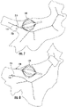
- FIG. 1 illustrates a depiction of the linear alignment 100 according to an aspect of the present system and method.
- Alignment 100 is defined in that ostium 110 is provided with a balloon 120 included therein to perform the ablation. Attached to the balloon 120 is a sheath 130.
- Each of ostium 110, balloon 120 and sheath 130 has an associated axis.
- the axis associated with ostium 110 is illustrated as an axis indicated by the labeled ostium axis arrow 115.
- the axis associated with balloon 120 is illustrated as an axis indicated by the labeled balloon axis arrow 125.
- the axis associated with sheath 130 is illustrated as an axis indicated by the labeled sheath axis arrow 135.
- Figure 2 illustrates a depiction of the lack of alignment 200 according to an aspect of the present system and method.
- the lack of alignment 200 is defined in that ostium 110 is provided with a balloon 120 included therein to perform the ablation.
- the balloon 120 passes through the sheath 130.
- Each of ostium 110, balloon 120 and sheath 130 again has an associated axis.
- the axis associated with ostium 110 is illustrated as an axis indicated by the labeled ostium axis arrow 115.
- the axis associated with balloon 120 is illustrated as an axis indicated by the labeled balloon axis arrow 125.
- the axis associated with sheath 130 is illustrated as an axis indicated by the labeled sheath axis arrow 135.
- Figure 3 illustrates a method 300 for aligning to achieve the linear alignment of FIG. 1 .
- Method 300 includes determining the axis of the vein at step 310, determining the axis of the balloon at step 320 and determining the axis of the sheath at step 330. While method 300 includes determining the axis of all three elements in steps 310-330, one of ordinary skill in the art will appreciate that this is only an embodiment, and embodiments where the vein and the balloon axes are determined along with other combinations of the three elements.
- Method 300 further includes aligning the determined axes to achieve the linear alignment of FIG. 1 at step 340.
- the axis of the vein is determined.
- the skeleton of the vein may be generated to provide the axis of the vein in cross section.
- FIG. 4 illustrates a depiction of an image 400 in which the axis of the vein 410 is shown.
- Axis 410 is determined by as described below and displayed in image 400.
- One of the many possible methods for finding the axis of the vein is described.
- the center point of the vein is determined using a virtual slice-cut through the shell of the map at the antrum to the vein by calculating a best-fit circle of the shell at the cut point and finding its geometrical center.
- a second point is determined by moving into the vein to perform a second virtual slice-cut, in which its center is found in a similar manner to the first cut.
- a third point is determined using a next slice and performing the same slice-cut steps described above. These slice-cut centers may be repetitively performed. The centers may be connected by a best fit line in order to identify the direction of the vein.
- the axis of the balloon is determined.
- the axis of the balloon may be determined by finding the vector connecting between the magnetic location sensor at the shaft of the balloon and the center of the best-fit circle of the locations of the balloon electrodes, to provide the axis vector.
- FIG. 5 illustrates a depiction of an image 500 in which the axis of the balloon 510 is shown.
- Axis 510 is determined by determining the center of a best fit circle 550 of the location of electrodes 520 of balloon 120 and drawing a line from the magnetic sensor 530 in the shaft 540 of balloon 120 to the center 550.
- Axis 510, as shown, is the vector connecting the center of magnetic sensor 530 and the determined center 550.
- Axis 510 is displayed in image 500.
- the axis of the sheath may be determined.
- the axis of the sheath may be determined using a magnetic sensor(s) or rings to visualize the sheath and calculate the vector of the sheath.
- FIG. 6 illustrates a depiction of an image 600 in which the axis 610 of the sheath 130 is shown.
- Axis 610 is determined as the direction vector passing between the locations 620 of the distal ring electrodes placed on the sheath 130.
- the ring electrodes placement at locations 620 along the sheath 130 may be in any location that allows a direction vector of the rings to be determined.
- One example shown in FIG. 6 is to use concentric evenly spaced rings on sheath 130.
- a direction of a magnetic sensor(s) mounted around the distal edge of the sheath 130 may be used.
- Axis 610 is displayed in image 600.
- the locations 620 and directions of the ring electrodes may be performed using the location of a navigation system, such as CARTO, for example.
- a navigation system such as CARTO
- a series of currents may be transmitted through the ring electrodes.
- a series of patch-electrodes on a patient's body may be used to read the received currents. Once read the locations may be calculated using distributed current ratios.
- magnetic locations may be utilized.
- the magnetic sensors generally may be coils, and may be constructed of either printed leads on a flexible printed circuit substrate or wire-wound coils. The vectors may then be displayed on the display of the navigation system.
- an estimate of any misalignment may be provided.
- the distance between the balloon axis and the vein axis may be estimated.
- the angle between any one of the axes of the balloon, the axis of the vein and the axis of the sheath may be estimated and provided in a display.
- the display provided may include the vectors and/or the distance between the vectors.
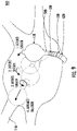
- FIG. 7 illustrates a depiction of an image in which the axis of the vein 710 and the axis of the balloon 720 are shown.
- the balloon 120 and vein 110 are also shown in the image.
- the angle between the axis of the vein 710 and the axis of the balloon 720 is provided.
- the arrow 710 is the direction vector of the vein axis and the arrow 720 is the direction vector of the balloon axis.
- FIG. 8 illustrates a depiction of an image in which the axis of the vein 710 and the axis of the balloon 720 are aligned to be in same direction. There is a shift/displacement between the balloon vector 720 and the vein axis 110. This shift/displacement may require correction in order to achieve balloon-to-vein alignment. Additionally, the balloon 120 and vein 110 are also shown in the image.
- the angle between the balloon direction vector and the vein direction vector and the shift/displacement between the vectors in each figure displays the vectors and/or the distance between the vectors until the distance between the vectors is zero indicating alignment between the axis of the balloon 720 and the axis of the vein 710. While FIGs. 7-8 depict the vein and balloon, similar configurations may be included with the sheath, and any combination of the vein, balloon and sheath.
- the present system and method for alignment of the balloon ablation catheter in the pulmonary vein may be expanded to include automated guidance of balloon position.
- This navigation may be performed by a deflectable sheath and by the deflection of the balloon.
- Such navigation may include forward and backward movement of the sheath and of the balloon, deflection of the sheath and of the balloon, and rotation of the sheath and of the balloon.
- FIG. 9 illustrates an exemplary depiction 900 of the automated guidance of balloon positioning in conjunction with the alignment described herein.
- Depiction 900 includes the balloon 120 including a deflectable balloon shaft 540, and a balloon catheter magnetic sensor 530 as described herein.
- Depiction 900 further includes a sheath 130 with a sheath locatable sensor 620 as described herein.
- Sheath 130 including magnetic sensors 620 and/or locatable electrodes on the front-end, a balloon 120 including a magnetic sensor 530 and a navigation system, such as CARTO ® 3, allows navigation by discerning the rotation, deflection and orientation of sheath 130 and balloon 120 and the relationship of each with respect to vein 110.
- the direction of sheath 130 and balloon 120 in order to occupy vein 110 may be realized via every twist/movement of the deflection knob of the sheath and of the balloon catheter.
- a pre-acquired, or concurrently acquired, 3D map of the chamber of the heart, and the current location, rotation, deflection state and orientation of sheath 130 and balloon 120 enables a prediction of the next position of balloon 120, relative to the 3D map, as a result of movement of sheath 130 and balloon 120. Additionally, or in conjunction, the optimal trajectory for placing balloon 120 into the correct position in vein 110 may be calculated.
- a step-by-step direction set for the operator to operate sheath 130 and balloon 120 advancement including rotation and deflection movements may be provided. This may allow the balloon 120 to optimally and quickly be positioned into vein 110.
- This same positioning algorithm and sensors may be also used for a robotic system, for automated guidance of sheath 130 and balloon 120 into vein 110.
- the alignment process attempts to move balloon 120 from the first initial position through a series of intermediate positions to the in-place for procedure position in vein 110.
- the balloon 120/sheath 130 are manipulated through a series of positions to arrive at vein 110. Specifically, from an initial position of balloon 120, the sheath 130 is deflected to arrive at a second intermediate position. From there the sheath 130 is deflected again to arrive at a third intermediate position. Then the sheath 130 is rotated to arrive at a fourth intermediate position. Finally, in a final alignment step the balloon 120 is advanced into the vein 110.
- exemplary maneuvers of the balloon 120 and sheath 130 in propagating to vein 110 are specific, they are provided as exemplary maneuvers. Any number of maneuvers may be required to reach vein 110. Similarly, the order of the specific maneuvers may be varied. As one would understand any combination, or order of maneuvers may be used.
- FIG. 10 illustrates a method 1000 of the automated guidance of balloon positioning associated with the depiction of FIG. 9 .
- method 1000 includes determining the current position and axis of at least one of the sheath 130 and balloon 120, This determination may be performed as described herein.
- Method 1000, at step 1020 includes determining the position and axis of vein 110. This determination may be performed as described herein.
- Method 1000, at step 1030 includes determining the steps for automated guidance from the current position of the balloon 120 to the vein 110.
- method includes the optional optimization of the steps for automated guidance in step 1030. This optimization 1035 may include minimizing the number of maneuvers required.
- the optimization at step 1035 may include a weighting of the kind of maneuvers, such as a preference for deflection for example.
- the optimization may include parameters that account for the time duration of each maneuver and the optimization at step 1035 minimizes the time required to reach vein 110, for example.
- method 1000 includes performing an initial alignment maneuver at step 1040.
- method 1000 includes performing a subsequent alignment maneuver. This subsequent maneuver may be looped at step 1055 by performing other maneuvers in sequence to guide the balloon 120 into the vein 110 as determined by the determined steps of step 1030.
- the vein 110 may be entered. Once configured in the vein 110 at step 1060, the ablation procedure may be performed at step 1070.
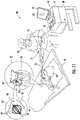
- FIG. 11 is an illustration of a catheter-based cardiac mapping system 20 comprising an ultrasound basket catheter 40, in accordance with an embodiment of the present invention.
- System 20 comprises a catheter 21, having a shaft 22 that may be navigated by a physician 30 into a heart 26 of a patient 28 lying on a table 29.
- physician 30 may insert shaft 22 through a sheath 23, while manipulating the distal end of shaft 22 using a manipulator 32 near the proximal end of the catheter and/or deflection from the sheath 23.
- basket catheter 40 may be fitted at the distal end of shaft 22.
- Basket catheter 40 may be inserted through sheath 23 in a collapsed state and may be then expanded within heart 26.
- basket catheter 40 may be configured to perform spatial mapping of a cardiac chamber of heart 26 by transmitting wide and narrow echo signals and receiving wide and narrow echo signals that were reflected from cardiac chamber surfaces 50, and which information may be used to form a map of the heart chamber and veins to which the catheter is intended to be navigated.
- the map of the chamber may be built using the locations of the electrodes of the basket or balloon catheter, through use of a 3D mapping system, such as CARTO ® .
- An inset 45 shows basket catheter 40 in an enlarged view, inside a cardiac chamber of heart 26.
- Console 24 may include a processor 41, such as a general-purpose computer, with suitable front end and interface circuits 38 for transmitting and receiving signals to and from catheter 21, as well as for controlling the other components of system 20.
- processor 41 may be further configured to receive multiple dual frequency (e.g., wide and narrow) echo signals and to calculate a map of a surface of a cardiac chamber from the echo signals.
- the surface of the surrounding anatomy may be presented to physician 30 on a display 27, e.g., in a graphical form of a mesh diagram 35.
- processor 41 may include a general-purpose computer, which may be programmed in software to carry out the functions described herein.
- the software may be downloaded to the computer in electronic form, over a network, for example, or it may, alternatively or additionally, be provided and/or stored on non-transitory tangible media, such as magnetic, optical, or electronic memory.
- non-transitory tangible media such as magnetic, optical, or electronic memory.
- FIG. 11 The example configuration shown in FIG. 11 is chosen purely for the sake of conceptual clarity. The disclosed techniques may similarly be applied using other system components and settings.
- system 20 may include additional components, such as ones for electrophysiological mapping and/or ablation.
- the elements of system 20 and the methods described herein may alternatively be applied in ultrasound mapping using catheters having other multi-arm geometries, or non-ultrasound 3D mapping using basket, balloon or other catheters types.
- the invention is based on the visualization capabilities of the system.
- the invention is aimed for linear alignment between the entities.
- the configuration could be changed according to the positioning and ablation strategy.
- This invention could be extended to other catheter types (e.g., focal catheters), if there is need for specific alignment during ablation.
Landscapes
- Health & Medical Sciences (AREA)
- Life Sciences & Earth Sciences (AREA)
- Engineering & Computer Science (AREA)
- Surgery (AREA)
- Heart & Thoracic Surgery (AREA)
- Public Health (AREA)
- Veterinary Medicine (AREA)
- Biomedical Technology (AREA)
- Animal Behavior & Ethology (AREA)
- General Health & Medical Sciences (AREA)
- Molecular Biology (AREA)
- Medical Informatics (AREA)
- Nuclear Medicine, Radiotherapy & Molecular Imaging (AREA)
- Physics & Mathematics (AREA)
- Cardiology (AREA)
- Biophysics (AREA)
- Robotics (AREA)
- Otolaryngology (AREA)
- Pathology (AREA)
- Hematology (AREA)
- Pulmonology (AREA)
- Anesthesiology (AREA)
- Plasma & Fusion (AREA)
- Child & Adolescent Psychology (AREA)
- Physiology (AREA)
- Surgical Instruments (AREA)
- Media Introduction/Drainage Providing Device (AREA)
Abstract
Description
- The subject matter disclosed herein relates to a system and method for alignment of a balloon ablation catheter in a pulmonary vein.
- The alignment of a balloon ablation catheter can be both difficult to achieve and critical to the ultimate success of the performed ablation. According to key opinion leaders in balloon ablation technologies (such as the BWI RF Heliostar, Cryoballoon, etc.), the relative orientation between the ablation balloon and the target pulmonary vein (PV) is an important parameter and considered a key predictor for generating an effective and single-shot ablation. The physicians aim for linear/axial alignment between the vein, the catheter, and the supporting sheath. This is understood to be the optimal ablation approach for using a balloon catheter. A guiding technique for alignment of the balloon ablation catheter and its sheath relative to the target pulmonary vein is considered an unmet clinical need. As such, alignment techniques to improve the alignment of the catheter and/or the ease of alignment of the catheter are needed.
- A system and method for achieving linear alignment between elements in a procedure are disclosed. The system and method include determining the axis of a first element, such as the ostium, of a plurality of elements utilized in the procedure, determining the axis of a second element, such as a catheter, of the plurality of elements utilized in the procedure, and aligning the determined axis of the first element and the determined axis of the second element. The method may include further determining the axis of a third element, such as a sheath of the catheter, of the plurality of elements utilized in the procedure and aligning the determined axis of the third element with the aligned axis of the first element and the aligned axis of the second element.
- A more detailed understanding may be had from the following description, given by way of example in conjunction with the accompanying drawings wherein:
-
FIG. 1 illustrates a depiction of the linear alignment according to an aspect of the present system and method; -
FIG. 2 illustrates a depiction of the lack of alignment according to an aspect of the present system and method; -
FIG. 3 illustrates a method of aligning to achieve the linear alignment ofFIG. 1 ; -
FIG. 4 illustrates a depiction of an image in which the axis of the vein is shown; -
FIG. 5 illustrates a depiction of an image in which the axis of the balloon is shown; -
FIG. 6 illustrates a depiction of an image in which the axis of the sheath is shown; -
FIG. 7 illustrates an exemplary depiction of an image in which the axis of the vein and the axis of the balloon are shown; -
FIG. 8 illustrates an exemplary depiction of an image in which the axis of the vein and the axis of the balloon are shown; -
FIG. 9 illustrates an exemplary depiction of the automated guidance of balloon positioning in conjunction with the alignment described herein; -
FIG. 10 illustrates a method of the automated guidance of balloon positioning associated with the depiction ofFIG. 9 ; and -
FIG. 11 is an example diagram of a catheter-based cardiac mapping system. - The present invention offers a three-dimensional (3D) visualization approach to enable the physician to achieve alignment between the target vein, the ablating catheter, and the sheath. Using an EP mapping system (such as CARTO, for example) that enables the visualization of the catheters, the sheaths, and vein anatomy, it is possible to visualize the spatial location and orientation of each. Thus, it is possible to calculate the relationship between the orientation of the catheters, the sheaths, and vein anatomy and to quantify the alignment. This quantification of the alignment may lend itself to automation and robotic alignment.
- According to one embodiment, it is possible to view the orientation vector of each of the target vein, the ablating catheter, and the sheath in the 3D space, and to provide a guide to the physicians to enable the physician to bring the catheter and/or the sheath to a desired spatial position and orientation, in accordance with the ablation strategy.
- Balloon ablation catheters, or other types of multi-electrode ablation catheters, are used in atrial fibrillation (AFIB) procedures to ablate the heart tissue at the ostium of the pulmonary veins (PVs), in order to isolate any electrical activity from within the veins to reach the left atria (LA) and therefore prevent it from causing atrial fibrillation disorder of the atria. Balloon ablation catheters, or other types of multi-electrode ablation catheters, are efficient if performing the electrical isolation of the veins through performing a single-shot isolation of the whole circumference of the vein within a single of few ablations.
-
Figure 1 illustrates a depiction of thelinear alignment 100 according to an aspect of the present system and method.Alignment 100 is defined in thatostium 110 is provided with aballoon 120 included therein to perform the ablation. Attached to theballoon 120 is asheath 130. - Each of
ostium 110,balloon 120 andsheath 130 has an associated axis. The axis associated withostium 110 is illustrated as an axis indicated by the labeledostium axis arrow 115. The axis associated withballoon 120 is illustrated as an axis indicated by the labeledballoon axis arrow 125. The axis associated withsheath 130 is illustrated as an axis indicated by the labeledsheath axis arrow 135. There is proximate alignment of the axes indicated byostium axis arrow 115,balloon axis arrow 125 andsheath axis arrow 135. -
Figure 2 illustrates a depiction of the lack ofalignment 200 according to an aspect of the present system and method. The lack ofalignment 200 is defined in thatostium 110 is provided with aballoon 120 included therein to perform the ablation. Theballoon 120 passes through thesheath 130. - Each of
ostium 110,balloon 120 andsheath 130 again has an associated axis. The axis associated withostium 110 is illustrated as an axis indicated by the labeledostium axis arrow 115. The axis associated withballoon 120 is illustrated as an axis indicated by the labeledballoon axis arrow 125. The axis associated withsheath 130 is illustrated as an axis indicated by the labeledsheath axis arrow 135. - As may be seen by comparing
ostium axis arrow 115,balloon axis arrow 125 andsheath axis arrow 135 inFigure 2 , there is substantial misalignment between the axis of the vein, balloon, and sheath. -
Figure 3 illustrates amethod 300 for aligning to achieve the linear alignment ofFIG. 1 .Method 300 includes determining the axis of the vein atstep 310, determining the axis of the balloon atstep 320 and determining the axis of the sheath atstep 330. Whilemethod 300 includes determining the axis of all three elements in steps 310-330, one of ordinary skill in the art will appreciate that this is only an embodiment, and embodiments where the vein and the balloon axes are determined along with other combinations of the three elements. -
Method 300 further includes aligning the determined axes to achieve the linear alignment ofFIG. 1 atstep 340. - In
step 310, the axis of the vein is determined. In order to perform this step ofmethod 300, the skeleton of the vein may be generated to provide the axis of the vein in cross section.FIG. 4 illustrates a depiction of animage 400 in which the axis of thevein 410 is shown.Axis 410 is determined by as described below and displayed inimage 400. One of the many possible methods for finding the axis of the vein is described. The center point of the vein is determined using a virtual slice-cut through the shell of the map at the antrum to the vein by calculating a best-fit circle of the shell at the cut point and finding its geometrical center. A second point is determined by moving into the vein to perform a second virtual slice-cut, in which its center is found in a similar manner to the first cut. A third point is determined using a next slice and performing the same slice-cut steps described above. These slice-cut centers may be repetitively performed. The centers may be connected by a best fit line in order to identify the direction of the vein. - In
step 320, the axis of the balloon is determined. The axis of the balloon may be determined by finding the vector connecting between the magnetic location sensor at the shaft of the balloon and the center of the best-fit circle of the locations of the balloon electrodes, to provide the axis vector.FIG. 5 illustrates a depiction of animage 500 in which the axis of theballoon 510 is shown.Axis 510 is determined by determining the center of a bestfit circle 550 of the location ofelectrodes 520 ofballoon 120 and drawing a line from themagnetic sensor 530 in theshaft 540 ofballoon 120 to thecenter 550.Axis 510, as shown, is the vector connecting the center ofmagnetic sensor 530 and thedetermined center 550.Axis 510 is displayed inimage 500. As would be understood by those possessing an ordinary skill in the pertinent arts, there are known algorithms for finding the best-fit circle from a set of points. For example, an algorithm based on the minimizing the sum of the squares of the distances between the locations of the electrodes to the closest points on the circle may be utilized. Alternatively, the algebraic and/or geometric distance to the points may be minimized. A combination of techniques may also be used with weighting utilized on top of the combination of algorithms. - In
step 330, the axis of the sheath may be determined. The axis of the sheath may be determined using a magnetic sensor(s) or rings to visualize the sheath and calculate the vector of the sheath.FIG. 6 illustrates a depiction of animage 600 in which theaxis 610 of thesheath 130 is shown.Axis 610 is determined as the direction vector passing between thelocations 620 of the distal ring electrodes placed on thesheath 130. The ring electrodes placement atlocations 620 along thesheath 130 may be in any location that allows a direction vector of the rings to be determined. One example shown inFIG. 6 is to use concentric evenly spaced rings onsheath 130. Alternatively, or additionally, a direction of a magnetic sensor(s) mounted around the distal edge of thesheath 130 may be used.Axis 610 is displayed inimage 600. - The
locations 620 and directions of the ring electrodes (magnetic sensors) may be performed using the location of a navigation system, such as CARTO, for example. For example, forring electrodes 620, a series of currents may be transmitted through the ring electrodes. A series of patch-electrodes on a patient's body may be used to read the received currents. Once read the locations may be calculated using distributed current ratios. - Alternatively, or additionally, magnetic locations may be utilized. By transmitting magnetic fields from static coils, such as from under a patient's bed, for example, the received magnetic fields may by measured using magnetic sensors. The magnetic sensors generally may be coils, and may be constructed of either printed leads on a flexible printed circuit substrate or wire-wound coils. The vectors may then be displayed on the display of the navigation system.
- In order to align the determined axes at
step 340 ofmethod 300, an estimate of any misalignment maybe provided. For example, the distance between the balloon axis and the vein axis may be estimated. The angle between any one of the axes of the balloon, the axis of the vein and the axis of the sheath may be estimated and provided in a display. The display provided may include the vectors and/or the distance between the vectors. -
FIG. 7 illustrates a depiction of an image in which the axis of thevein 710 and the axis of theballoon 720 are shown. Theballoon 120 andvein 110 are also shown in the image. The angle between the axis of thevein 710 and the axis of theballoon 720 is provided. Thearrow 710 is the direction vector of the vein axis and thearrow 720 is the direction vector of the balloon axis. -
FIG. 8 illustrates a depiction of an image in which the axis of thevein 710 and the axis of theballoon 720 are aligned to be in same direction. There is a shift/displacement between theballoon vector 720 and thevein axis 110. This shift/displacement may require correction in order to achieve balloon-to-vein alignment. Additionally, theballoon 120 andvein 110 are also shown in the image. - As may be observed from the images of
FIGs. 7-8 , the angle between the balloon direction vector and the vein direction vector and the shift/displacement between the vectors in each figure displays the vectors and/or the distance between the vectors until the distance between the vectors is zero indicating alignment between the axis of theballoon 720 and the axis of thevein 710. WhileFIGs. 7-8 depict the vein and balloon, similar configurations may be included with the sheath, and any combination of the vein, balloon and sheath. - As discussed herein, navigating and positioning a catheter, such as a balloon catheter into the vein often requires complicated and potentially time-consuming maneuvering and experience. As described, the present system and method for alignment of the balloon ablation catheter in the pulmonary vein may be expanded to include automated guidance of balloon position. This navigation may be performed by a deflectable sheath and by the deflection of the balloon. Such navigation may include forward and backward movement of the sheath and of the balloon, deflection of the sheath and of the balloon, and rotation of the sheath and of the balloon.
-
FIG. 9 illustrates anexemplary depiction 900 of the automated guidance of balloon positioning in conjunction with the alignment described herein.Depiction 900 includes theballoon 120 including adeflectable balloon shaft 540, and a balloon cathetermagnetic sensor 530 as described herein.Depiction 900 further includes asheath 130 with a sheathlocatable sensor 620 as described herein. -
Sheath 130 includingmagnetic sensors 620 and/or locatable electrodes on the front-end, aballoon 120 including amagnetic sensor 530 and a navigation system, such asCARTO ® 3, allows navigation by discerning the rotation, deflection and orientation ofsheath 130 andballoon 120 and the relationship of each with respect tovein 110. The direction ofsheath 130 andballoon 120 in order to occupyvein 110 may be realized via every twist/movement of the deflection knob of the sheath and of the balloon catheter. - A pre-acquired, or concurrently acquired, 3D map of the chamber of the heart, and the current location, rotation, deflection state and orientation of
sheath 130 andballoon 120 enables a prediction of the next position ofballoon 120, relative to the 3D map, as a result of movement ofsheath 130 andballoon 120. Additionally, or in conjunction, the optimal trajectory for placingballoon 120 into the correct position invein 110 may be calculated. - By calculating the optimal trajectory of
balloon 120 to arrive invein 110, a step-by-step direction set for the operator to operatesheath 130 andballoon 120 advancement including rotation and deflection movements may be provided. This may allow theballoon 120 to optimally and quickly be positioned intovein 110. This same positioning algorithm and sensors may be also used for a robotic system, for automated guidance ofsheath 130 andballoon 120 intovein 110. - In the exemplary alignment illustrated in
FIG. 9 , the alignment process attempts to moveballoon 120 from the first initial position through a series of intermediate positions to the in-place for procedure position invein 110. In the exemplary illustration, theballoon 120/sheath 130 are manipulated through a series of positions to arrive atvein 110. Specifically, from an initial position ofballoon 120, thesheath 130 is deflected to arrive at a second intermediate position. From there thesheath 130 is deflected again to arrive at a third intermediate position. Then thesheath 130 is rotated to arrive at a fourth intermediate position. Finally, in a final alignment step theballoon 120 is advanced into thevein 110. While the exemplary maneuvers of theballoon 120 andsheath 130 in propagating tovein 110 are specific, they are provided as exemplary maneuvers. Any number of maneuvers may be required to reachvein 110. Similarly, the order of the specific maneuvers may be varied. As one would understand any combination, or order of maneuvers may be used. -
FIG. 10 illustrates amethod 1000 of the automated guidance of balloon positioning associated with the depiction ofFIG. 9 . As illustrated inFIG. 10 , atstep 1010method 1000 includes determining the current position and axis of at least one of thesheath 130 andballoon 120, This determination may be performed as described herein.Method 1000, atstep 1020, includes determining the position and axis ofvein 110. This determination may be performed as described herein.Method 1000, atstep 1030, includes determining the steps for automated guidance from the current position of theballoon 120 to thevein 110. Atstep 1035, method includes the optional optimization of the steps for automated guidance instep 1030. Thisoptimization 1035 may include minimizing the number of maneuvers required. Alternatively, the optimization atstep 1035 may include a weighting of the kind of maneuvers, such as a preference for deflection for example. Similarly, the optimization may include parameters that account for the time duration of each maneuver and the optimization atstep 1035 minimizes the time required to reachvein 110, for example. - Once the steps are determined at
step 1030, and optimized atstep 1035 if desired,method 1000 includes performing an initial alignment maneuver atstep 1040. Atstep 1050,method 1000 includes performing a subsequent alignment maneuver. This subsequent maneuver may be looped atstep 1055 by performing other maneuvers in sequence to guide theballoon 120 into thevein 110 as determined by the determined steps ofstep 1030. Atstep 1060, once the maneuvers are performed, thevein 110 may be entered. Once configured in thevein 110 atstep 1060, the ablation procedure may be performed atstep 1070. -
FIG. 11 is an illustration of a catheter-basedcardiac mapping system 20 comprising anultrasound basket catheter 40, in accordance with an embodiment of the present invention. It will be understood that although a basket shape is disclosed throughout, any shape catheter comprising multiple transducers may be used to implement the embodiments disclosed herein.System 20 comprises acatheter 21, having ashaft 22 that may be navigated by aphysician 30 into aheart 26 of a patient 28 lying on a table 29. As shown inFIG. 11 ,physician 30 may insertshaft 22 through asheath 23, while manipulating the distal end ofshaft 22 using amanipulator 32 near the proximal end of the catheter and/or deflection from thesheath 23. As shown in aninset 25,basket catheter 40 may be fitted at the distal end ofshaft 22.Basket catheter 40 may be inserted throughsheath 23 in a collapsed state and may be then expanded withinheart 26. - In an embodiment,
basket catheter 40 may be configured to perform spatial mapping of a cardiac chamber ofheart 26 by transmitting wide and narrow echo signals and receiving wide and narrow echo signals that were reflected from cardiac chamber surfaces 50, and which information may be used to form a map of the heart chamber and veins to which the catheter is intended to be navigated. Alternatively, the map of the chamber may be built using the locations of the electrodes of the basket or balloon catheter, through use of a 3D mapping system, such as CARTO®. An inset 45 showsbasket catheter 40 in an enlarged view, inside a cardiac chamber ofheart 26. - The proximal end of
catheter 21 may be connected to aconsole 24.Console 24 may include aprocessor 41, such as a general-purpose computer, with suitable front end andinterface circuits 38 for transmitting and receiving signals to and fromcatheter 21, as well as for controlling the other components ofsystem 20. In some embodiments,processor 41 may be further configured to receive multiple dual frequency (e.g., wide and narrow) echo signals and to calculate a map of a surface of a cardiac chamber from the echo signals. In an embodiment, the surface of the surrounding anatomy may be presented tophysician 30 on adisplay 27, e.g., in a graphical form of a mesh diagram 35. - As noted above,
processor 41 may include a general-purpose computer, which may be programmed in software to carry out the functions described herein. The software may be downloaded to the computer in electronic form, over a network, for example, or it may, alternatively or additionally, be provided and/or stored on non-transitory tangible media, such as magnetic, optical, or electronic memory. The example configuration shown inFIG. 11 is chosen purely for the sake of conceptual clarity. The disclosed techniques may similarly be applied using other system components and settings. Additionally,system 20 may include additional components, such as ones for electrophysiological mapping and/or ablation. Although the pictured embodiment relates specifically to the use of an ultrasound basket catheter for cardiac mapping, the elements ofsystem 20 and the methods described herein may alternatively be applied in ultrasound mapping using catheters having other multi-arm geometries, or non-ultrasound 3D mapping using basket, balloon or other catheters types. - Currently, physicians navigate the catheters (based on Fluoroscopy, ICE, or a mapping system) and independently (without guidance or quantitative tools) try to understand the relative orientation between the entities and to align the moving parts. There is no quantification of the alignment degree.
- The invention is based on the visualization capabilities of the system. The invention is aimed for linear alignment between the entities. The configuration could be changed according to the positioning and ablation strategy. This invention could be extended to other catheter types (e.g., focal catheters), if there is need for specific alignment during ablation.
- While the present description details correcting linear alignment of the balloon, ostium, and sheath, this concepts in this description may be used to assist physicians in achieving non-linear, slanted, lateral ablation, or any other combination of balloon-vein-sheath configurations for an ablation approach, as needed. While generally the present examples provide for linear alignment as this is often preferred in ablations, other combinations of balloon-vein-sheath configurations, including non-linear, slanted, lateral ablations, etc., may be configured.
- Although features and elements are described above in particular combinations, one of ordinary skill in the art will appreciate that each feature or element can be used alone or in any combination with the other features and elements. In addition, the methods described herein may be implemented in a computer program, software, or firmware incorporated in a computer-readable medium for execution by a computer or processor.
-
- 1. A method for achieving linear alignment between elements in a procedure, the method comprising
- determining the axis of a first element of a plurality of elements utilized in the procedure;
- determining the axis of a second element of the plurality of elements utilized in the procedure; and
- aligning the determined axis of the first element and the determined axis of the second element.
- 2. The method of
aspect 1, further comprising determining the axis of a third element of the plurality of elements utilized in the procedure and aligning the determined axis of the third element with the aligned axis of the first element and the aligned axis of the second element. - 3. The method of
aspect 2, where the third element comprises a sheath of a surgical tool. - 4. The method of
aspect 3, wherein the sheath comprises a sheath of a catheter. - 5. The method of
aspect 1, wherein the first element comprises an ostium. - 6. The method of
aspect 1, wherein the second element comprises a surgical tool. - 7. The method of
aspect 1, wherein the second element comprises a catheter. - 8. The method of
aspect 1, wherein the second element comprises a balloon catheter. - 9. A method to assist in a robotic procedure for achieving linear alignment between elements in the procedure, the method comprising
- determining the axis of a first element of a plurality of elements utilized in the procedure;
- determining the axis of a second element of the plurality of elements utilized in the procedure; and
- aligning the determined axis of the first element and the determined axis of the second element by providing control of the first element and the second element for automatic alignment of the determined axis of the first element and the determined axis of the second element.
- 10. The method of aspect 9, further comprising determining the axis of a third element of the plurality of elements utilized in the procedure and aligning the determined axis of the third element with the aligned axis of the first element and the aligned axis of the second element.
- 11. The method of aspect 10, where the third element comprises a sheath of a surgical tool.
- 12. The method of aspect 11, wherein the sheath comprises a sheath of a catheter.
- 13. The method of aspect 9, wherein the first element comprises an ostium.
- 14. The method of aspect 9, wherein the second element comprises a surgical tool.
- 15. The method of aspect 9, wherein the second element comprises a catheter.
- 16. The method of aspect 9, wherein the second element comprises a balloon catheter.
- 17. The method of aspect 9, wherein the first element is a deflectable sheath and the second element is a deflectable catheter.
- 18. A method to assist in a robotic procedure for achieving a preferred alignment between elements in the procedure, the method comprising
- determining the axis of a first element of a plurality of elements utilized in the procedure;
- determining the axis of a second element of the plurality of elements utilized in the procedure; and
- aligning the determined axis of the first element and the determined axis of the second element by providing control of the first element and the second element for automatic alignment of the determined axis of the first element and the determined axis of the second element.
- 19. The method of aspect 18, further comprising determining the axis of a third element of the plurality of elements utilized in the procedure and aligning the determined axis of the third element with the aligned axis of the first element and the aligned axis of the second element.
- 20. The method of aspect 10, where the third element comprises a sheath of a surgical tool, the first element comprises a deflectable sheath and the second element comprises a deflectable catheter.
Claims (10)
- A system for achieving a preferred alignment between elements in a robotic procedure, comprising:
a processor configured to:determine the axis of a first element of a plurality of elements utilized in the procedure;determine the axis of a second element of the plurality of elements utilized in the procedure; andalign the determined axis of the first element and the determined axis of the second element by providing control of the first element and the second element for automatic alignment of the determined axis of the first element and the determined axis of the second element. - The system of claim 1, the processor further configure to determine the axis of a third element of the plurality of elements utilized in the procedure and align the determined axis of the third element with the aligned axis of the first element and the aligned axis of the second element.
- The system of claim 2, where the third element comprises a sheath of a surgical tool.
- The system of claim 3, wherein the sheath comprises a sheath of a catheter.
- The system of claim 1, wherein the first element comprises an ostium.
- The system of claim 1, wherein the second element comprises a surgical tool.
- The system of claim 1, wherein the second element comprises a catheter.
- The system of claim 1, wherein the second element comprises a balloon catheter.
- The system of claim 1, wherein the first element is a deflectable sheath and the second element is a deflectable catheter.
- The system of any preceding claim, wherein the preferred alignment is a linear alignment.
Applications Claiming Priority (1)
| Application Number | Priority Date | Filing Date | Title |
|---|---|---|---|
| US17/169,183 US20220249172A1 (en) | 2021-02-05 | 2021-02-05 | System and method for alignment of balloon ablation catheter in pulmonary vein |
Publications (3)
| Publication Number | Publication Date |
|---|---|
| EP4039214A1 true EP4039214A1 (en) | 2022-08-10 |
| EP4039214C0 EP4039214C0 (en) | 2025-12-03 |
| EP4039214B1 EP4039214B1 (en) | 2025-12-03 |
Family
ID=80682324
Family Applications (1)
| Application Number | Title | Priority Date | Filing Date |
|---|---|---|---|
| EP22155139.3A Active EP4039214B1 (en) | 2021-02-05 | 2022-02-04 | System for alignment of balloon ablation catheter in pulmonary vein |
Country Status (5)
| Country | Link |
|---|---|
| US (1) | US20220249172A1 (en) |
| EP (1) | EP4039214B1 (en) |
| JP (1) | JP7793402B2 (en) |
| CN (1) | CN114869445A (en) |
| IL (1) | IL290082A (en) |
Families Citing this family (2)
| Publication number | Priority date | Publication date | Assignee | Title |
|---|---|---|---|---|
| EP4326179A4 (en) * | 2021-04-21 | 2025-07-09 | Yakov Nedlin | METHOD AND DEVICE FOR HIGH-POWER ABLATION |
| EP4642322A1 (en) * | 2022-12-30 | 2025-11-05 | Boston Scientific Scimed Inc. | Catheter assembly tracking and visualization |
Citations (5)
| Publication number | Priority date | Publication date | Assignee | Title |
|---|---|---|---|---|
| WO2013192598A1 (en) * | 2012-06-21 | 2013-12-27 | Excelsius Surgical, L.L.C. | Surgical robot platform |
| WO2018017811A1 (en) * | 2016-07-21 | 2018-01-25 | Restoration Robotics, Inc. | Automated system and method for hair removal |
| WO2018064398A1 (en) * | 2016-09-28 | 2018-04-05 | Project Moray, Inc. | Arrhythmia diagnostic and/or therapy delivery methods and devices, and robotic systems for other uses |
| WO2018106569A1 (en) * | 2016-12-09 | 2018-06-14 | St. Jude Medical, Cardiology Division, Inc. | Pulmonary vein isolation balloon catheter |
| EP3960073A1 (en) * | 2020-08-28 | 2022-03-02 | Biosense Webster (Israel) Ltd | Fitting and directing an expandable catheter based on automatic pulmonary veins anatomical characterization |
Family Cites Families (22)
| Publication number | Priority date | Publication date | Assignee | Title |
|---|---|---|---|---|
| US7379574B2 (en) * | 2002-11-27 | 2008-05-27 | The Board Of Trustees Of The Leland Stanford Junior University | Quantification of vascular irregularity |
| JP4441664B2 (en) * | 2004-07-28 | 2010-03-31 | 株式会社ユネクス | Blood vessel shape measuring device and blood flow measuring device |
| WO2006079018A2 (en) * | 2005-01-19 | 2006-07-27 | The Johns Hopkins University | Method of assessing vascular reactivity using magnetic resonance imaging, applications program and media embodying same |
| AU2009100486A6 (en) * | 2009-05-23 | 2010-03-18 | Warren, Hayley Ms | HALO Disc |
| US10499984B2 (en) * | 2012-07-18 | 2019-12-10 | Bernard Boon Chye Lim | Apparatus and method for assessing tissue treatment |
| US9818231B2 (en) * | 2013-08-13 | 2017-11-14 | Boston Scientific Scimed, Inc. | Computer visualization of anatomical items |
| US20150087911A1 (en) * | 2013-09-26 | 2015-03-26 | Gyrus Acmi, Inc. D.B.A Olympus Surgical Technologies America | Endoscope sheath deflection devices |
| US9345550B2 (en) * | 2013-10-31 | 2016-05-24 | Pacesetter, Inc. | Method and system for characterizing stimulus sites and providing implant guidance |
| US9788893B2 (en) * | 2014-11-20 | 2017-10-17 | Biosense Webster (Israel) Ltd. | Catheter with soft distal tip for mapping and ablating tubular region |
| WO2017216318A1 (en) * | 2016-06-16 | 2017-12-21 | Koninklijke Philips N.V. | A method and apparatus for mapping at least part of a structure in an image of at least part of a body of a subject |
| US10702342B2 (en) * | 2016-09-08 | 2020-07-07 | Medtronic, Inc. | Navigation guidance method for complex catheters |
| US10096105B2 (en) * | 2016-09-08 | 2018-10-09 | Medtronic Cryocath Lp | Method of determining target treatment locations |
| WO2018106538A1 (en) * | 2016-12-09 | 2018-06-14 | St. Jude Medical, Cardiology Division, Inc. | Pulmonary vein isolation balloon catheter |
| EP4186450B1 (en) * | 2016-12-09 | 2025-01-22 | St. Jude Medical, Cardiology Division, Inc. | Pulmonary vein isolation balloon catheter |
| WO2018203304A1 (en) * | 2017-05-05 | 2018-11-08 | Scopis Gmbh | Surgical navigation system |
| US11026758B2 (en) * | 2017-06-28 | 2021-06-08 | Auris Health, Inc. | Medical robotics systems implementing axis constraints during actuation of one or more motorized joints |
| CN110831536B (en) * | 2017-12-06 | 2021-09-07 | 奥瑞斯健康公司 | System and method for correcting for uncommanded instrument roll |
| JP7008522B2 (en) * | 2018-02-01 | 2022-01-25 | テルモ株式会社 | Medical system |
| US20200038638A1 (en) * | 2018-08-06 | 2020-02-06 | Biosense Webster (Israel) Ltd. | Balloon positioning using magnetic resonance imaging (mri) blood flow measurements |
| WO2020131186A1 (en) * | 2018-12-20 | 2020-06-25 | Auris Health, Inc. | Systems and methods for robotic arm alignment and docking |
| CN111916183B (en) * | 2019-05-10 | 2023-03-14 | 北京航空航天大学 | Modeling method, device, equipment and storage medium of dynamic cardiovascular system |
| US10842572B1 (en) * | 2019-11-25 | 2020-11-24 | Farapulse, Inc. | Methods, systems, and apparatuses for tracking ablation devices and generating lesion lines |
-
2021
- 2021-02-05 US US17/169,183 patent/US20220249172A1/en active Pending
-
2022
- 2022-01-24 IL IL290082A patent/IL290082A/en unknown
- 2022-01-29 CN CN202210111268.7A patent/CN114869445A/en active Pending
- 2022-02-04 EP EP22155139.3A patent/EP4039214B1/en active Active
- 2022-02-04 JP JP2022016232A patent/JP7793402B2/en active Active
Patent Citations (5)
| Publication number | Priority date | Publication date | Assignee | Title |
|---|---|---|---|---|
| WO2013192598A1 (en) * | 2012-06-21 | 2013-12-27 | Excelsius Surgical, L.L.C. | Surgical robot platform |
| WO2018017811A1 (en) * | 2016-07-21 | 2018-01-25 | Restoration Robotics, Inc. | Automated system and method for hair removal |
| WO2018064398A1 (en) * | 2016-09-28 | 2018-04-05 | Project Moray, Inc. | Arrhythmia diagnostic and/or therapy delivery methods and devices, and robotic systems for other uses |
| WO2018106569A1 (en) * | 2016-12-09 | 2018-06-14 | St. Jude Medical, Cardiology Division, Inc. | Pulmonary vein isolation balloon catheter |
| EP3960073A1 (en) * | 2020-08-28 | 2022-03-02 | Biosense Webster (Israel) Ltd | Fitting and directing an expandable catheter based on automatic pulmonary veins anatomical characterization |
Also Published As
| Publication number | Publication date |
|---|---|
| EP4039214C0 (en) | 2025-12-03 |
| US20220249172A1 (en) | 2022-08-11 |
| CN114869445A (en) | 2022-08-09 |
| IL290082A (en) | 2022-09-01 |
| JP2022120831A (en) | 2022-08-18 |
| JP7793402B2 (en) | 2026-01-05 |
| EP4039214B1 (en) | 2025-12-03 |
Similar Documents
| Publication | Publication Date | Title |
|---|---|---|
| EP3766415B1 (en) | Visual guidance for positioning a distal end of a medical probe | |
| US11064930B2 (en) | Automatic tracking and adjustment of the view angle during catheter ablation treatment | |
| JP5285270B2 (en) | Automatic guide wire operation system | |
| US20060116576A1 (en) | System and use thereof to provide indication of proximity between catheter and location of interest in 3-D space | |
| EP4039214B1 (en) | System for alignment of balloon ablation catheter in pulmonary vein | |
| US20200337766A1 (en) | Device and accessories for a percutaneous endoscopic access and ablation systems | |
| US11844567B2 (en) | Fitting and directing an expandable catheter based on automatic pulmonary veins anatomical characterization | |
| EP4190257B1 (en) | Planar catheter with overlapping electrode pairs | |
| US20240277251A1 (en) | Devices, systems, and methods for improving the accuracy and utility of imaging for cardiovascular procedures | |
| US20170095289A1 (en) | System And Method For Representation And Visualization Of Catheter Applied Force And Power | |
| JP2022019680A (en) | Medical apparatus and method of use thereof | |
| EP4134006B1 (en) | Presenting the selected position of multiple electrodes and quality measurements of tissue ablation in a blood vessel using a two-dimensional map | |
| US11995849B2 (en) | Automatic registration of an anatomical map to a previous anatomical map | |
| CN119700204A (en) | View-based robotic intracardiac catheter guidance | |
| CN121196731A (en) | Readable storage media, magnetic navigation positioning systems, and interventional surgical systems |
Legal Events
| Date | Code | Title | Description |
|---|---|---|---|
| PUAI | Public reference made under article 153(3) epc to a published international application that has entered the european phase |
Free format text: ORIGINAL CODE: 0009012 |
|
| STAA | Information on the status of an ep patent application or granted ep patent |
Free format text: STATUS: THE APPLICATION HAS BEEN PUBLISHED |
|
| AK | Designated contracting states |
Kind code of ref document: A1 Designated state(s): AL AT BE BG CH CY CZ DE DK EE ES FI FR GB GR HR HU IE IS IT LI LT LU LV MC MK MT NL NO PL PT RO RS SE SI SK SM TR |
|
| STAA | Information on the status of an ep patent application or granted ep patent |
Free format text: STATUS: REQUEST FOR EXAMINATION WAS MADE |
|
| 17P | Request for examination filed |
Effective date: 20230209 |
|
| RBV | Designated contracting states (corrected) |
Designated state(s): AL AT BE BG CH CY CZ DE DK EE ES FI FR GB GR HR HU IE IS IT LI LT LU LV MC MK MT NL NO PL PT RO RS SE SI SK SM TR |
|
| STAA | Information on the status of an ep patent application or granted ep patent |
Free format text: STATUS: EXAMINATION IS IN PROGRESS |
|
| 17Q | First examination report despatched |
Effective date: 20241203 |
|
| GRAP | Despatch of communication of intention to grant a patent |
Free format text: ORIGINAL CODE: EPIDOSNIGR1 |
|
| STAA | Information on the status of an ep patent application or granted ep patent |
Free format text: STATUS: GRANT OF PATENT IS INTENDED |
|
| RIC1 | Information provided on ipc code assigned before grant |
Ipc: A61B 18/14 20060101AFI20250703BHEP Ipc: A61M 25/10 20130101ALI20250703BHEP Ipc: A61B 34/20 20160101ALI20250703BHEP Ipc: A61B 34/32 20160101ALI20250703BHEP Ipc: A61B 17/00 20060101ALN20250703BHEP Ipc: A61B 34/30 20160101ALN20250703BHEP Ipc: A61B 18/00 20060101ALN20250703BHEP Ipc: A61B 90/00 20160101ALN20250703BHEP |
|
| INTG | Intention to grant announced |
Effective date: 20250729 |
|
| GRAS | Grant fee paid |
Free format text: ORIGINAL CODE: EPIDOSNIGR3 |
|
| GRAA | (expected) grant |
Free format text: ORIGINAL CODE: 0009210 |
|
| STAA | Information on the status of an ep patent application or granted ep patent |
Free format text: STATUS: THE PATENT HAS BEEN GRANTED |
|
| AK | Designated contracting states |
Kind code of ref document: B1 Designated state(s): AL AT BE BG CH CY CZ DE DK EE ES FI FR GB GR HR HU IE IS IT LI LT LU LV MC MK MT NL NO PL PT RO RS SE SI SK SM TR |
|
| REG | Reference to a national code |
Ref country code: CH Ref legal event code: F10 Free format text: ST27 STATUS EVENT CODE: U-0-0-F10-F00 (AS PROVIDED BY THE NATIONAL OFFICE) Effective date: 20251203 Ref country code: GB Ref legal event code: FG4D |
|
| REG | Reference to a national code |
Ref country code: DE Ref legal event code: R096 Ref document number: 602022025946 Country of ref document: DE |
|
| REG | Reference to a national code |
Ref country code: IE Ref legal event code: FG4D |
|
| U01 | Request for unitary effect filed |
Effective date: 20251216 |
|
| U07 | Unitary effect registered |
Designated state(s): AT BE BG DE DK EE FI FR IT LT LU LV MT NL PT RO SE SI Effective date: 20251223 |
|
| U20 | Renewal fee for the european patent with unitary effect paid |
Year of fee payment: 5 Effective date: 20260106 |
|
| PGFP | Annual fee paid to national office [announced via postgrant information from national office to epo] |
Ref country code: GB Payment date: 20260106 Year of fee payment: 5 |
|
| PG25 | Lapsed in a contracting state [announced via postgrant information from national office to epo] |
Ref country code: ES Free format text: LAPSE BECAUSE OF FAILURE TO SUBMIT A TRANSLATION OF THE DESCRIPTION OR TO PAY THE FEE WITHIN THE PRESCRIBED TIME-LIMIT Effective date: 20251203 |
|
| PG25 | Lapsed in a contracting state [announced via postgrant information from national office to epo] |
Ref country code: NO Free format text: LAPSE BECAUSE OF FAILURE TO SUBMIT A TRANSLATION OF THE DESCRIPTION OR TO PAY THE FEE WITHIN THE PRESCRIBED TIME-LIMIT Effective date: 20260303 |
|
| PG25 | Lapsed in a contracting state [announced via postgrant information from national office to epo] |
Ref country code: HR Free format text: LAPSE BECAUSE OF FAILURE TO SUBMIT A TRANSLATION OF THE DESCRIPTION OR TO PAY THE FEE WITHIN THE PRESCRIBED TIME-LIMIT Effective date: 20251203 |
|
| PG25 | Lapsed in a contracting state [announced via postgrant information from national office to epo] |
Ref country code: RS Free format text: LAPSE BECAUSE OF FAILURE TO SUBMIT A TRANSLATION OF THE DESCRIPTION OR TO PAY THE FEE WITHIN THE PRESCRIBED TIME-LIMIT Effective date: 20260303 |
|
| PG25 | Lapsed in a contracting state [announced via postgrant information from national office to epo] |
Ref country code: PL Free format text: LAPSE BECAUSE OF FAILURE TO SUBMIT A TRANSLATION OF THE DESCRIPTION OR TO PAY THE FEE WITHIN THE PRESCRIBED TIME-LIMIT Effective date: 20251203 |