EP4039072A1 - Agricultural or work vehicle equipped with a hydraulic lift - Google Patents
Agricultural or work vehicle equipped with a hydraulic lift Download PDFInfo
- Publication number
- EP4039072A1 EP4039072A1 EP22155207.8A EP22155207A EP4039072A1 EP 4039072 A1 EP4039072 A1 EP 4039072A1 EP 22155207 A EP22155207 A EP 22155207A EP 4039072 A1 EP4039072 A1 EP 4039072A1
- Authority
- EP
- European Patent Office
- Prior art keywords
- hydraulic
- lift
- expansion chambers
- arms
- control device
- Prior art date
- Legal status (The legal status is an assumption and is not a legal conclusion. Google has not performed a legal analysis and makes no representation as to the accuracy of the status listed.)
- Granted
Links
Images


Classifications
-
- A—HUMAN NECESSITIES
- A01—AGRICULTURE; FORESTRY; ANIMAL HUSBANDRY; HUNTING; TRAPPING; FISHING
- A01B—SOIL WORKING IN AGRICULTURE OR FORESTRY; PARTS, DETAILS, OR ACCESSORIES OF AGRICULTURAL MACHINES OR IMPLEMENTS, IN GENERAL
- A01B59/00—Devices specially adapted for connection between animals or tractors and agricultural machines or implements
- A01B59/04—Devices specially adapted for connection between animals or tractors and agricultural machines or implements for machines pulled or pushed by a tractor
- A01B59/042—Devices specially adapted for connection between animals or tractors and agricultural machines or implements for machines pulled or pushed by a tractor having pulling means arranged on the rear part of the tractor
- A01B59/043—Devices specially adapted for connection between animals or tractors and agricultural machines or implements for machines pulled or pushed by a tractor having pulling means arranged on the rear part of the tractor supported at three points, e.g. by quick-release couplings
-
- F—MECHANICAL ENGINEERING; LIGHTING; HEATING; WEAPONS; BLASTING
- F15—FLUID-PRESSURE ACTUATORS; HYDRAULICS OR PNEUMATICS IN GENERAL
- F15B—SYSTEMS ACTING BY MEANS OF FLUIDS IN GENERAL; FLUID-PRESSURE ACTUATORS, e.g. SERVOMOTORS; DETAILS OF FLUID-PRESSURE SYSTEMS, NOT OTHERWISE PROVIDED FOR
- F15B11/00—Servomotor systems without provision for follow-up action ; Circuits therefor
- F15B11/16—Servomotor systems without provision for follow-up action ; Circuits therefor with two or more servomotors
- F15B11/22—Synchronisation of the movement of two or more servomotors
-
- F—MECHANICAL ENGINEERING; LIGHTING; HEATING; WEAPONS; BLASTING
- F15—FLUID-PRESSURE ACTUATORS; HYDRAULICS OR PNEUMATICS IN GENERAL
- F15B—SYSTEMS ACTING BY MEANS OF FLUIDS IN GENERAL; FLUID-PRESSURE ACTUATORS, e.g. SERVOMOTORS; DETAILS OF FLUID-PRESSURE SYSTEMS, NOT OTHERWISE PROVIDED FOR
- F15B2211/00—Circuits for servomotor systems
- F15B2211/30—Directional control
- F15B2211/305—Directional control characterised by the type of valves
- F15B2211/3052—Shuttle valves
-
- F—MECHANICAL ENGINEERING; LIGHTING; HEATING; WEAPONS; BLASTING
- F15—FLUID-PRESSURE ACTUATORS; HYDRAULICS OR PNEUMATICS IN GENERAL
- F15B—SYSTEMS ACTING BY MEANS OF FLUIDS IN GENERAL; FLUID-PRESSURE ACTUATORS, e.g. SERVOMOTORS; DETAILS OF FLUID-PRESSURE SYSTEMS, NOT OTHERWISE PROVIDED FOR
- F15B2211/00—Circuits for servomotor systems
- F15B2211/30—Directional control
- F15B2211/305—Directional control characterised by the type of valves
- F15B2211/30525—Directional control valves, e.g. 4/3-directional control valve
- F15B2211/3053—In combination with a pressure compensating valve
- F15B2211/30535—In combination with a pressure compensating valve the pressure compensating valve is arranged between pressure source and directional control valve
-
- F—MECHANICAL ENGINEERING; LIGHTING; HEATING; WEAPONS; BLASTING
- F15—FLUID-PRESSURE ACTUATORS; HYDRAULICS OR PNEUMATICS IN GENERAL
- F15B—SYSTEMS ACTING BY MEANS OF FLUIDS IN GENERAL; FLUID-PRESSURE ACTUATORS, e.g. SERVOMOTORS; DETAILS OF FLUID-PRESSURE SYSTEMS, NOT OTHERWISE PROVIDED FOR
- F15B2211/00—Circuits for servomotor systems
- F15B2211/30—Directional control
- F15B2211/305—Directional control characterised by the type of valves
- F15B2211/3056—Assemblies of multiple valves
- F15B2211/30565—Assemblies of multiple valves having multiple valves for a single output member, e.g. for creating higher valve function by use of multiple valves like two 2/2-valves replacing a 5/3-valve
- F15B2211/3057—Assemblies of multiple valves having multiple valves for a single output member, e.g. for creating higher valve function by use of multiple valves like two 2/2-valves replacing a 5/3-valve having two valves, one for each port of a double-acting output member
-
- F—MECHANICAL ENGINEERING; LIGHTING; HEATING; WEAPONS; BLASTING
- F15—FLUID-PRESSURE ACTUATORS; HYDRAULICS OR PNEUMATICS IN GENERAL
- F15B—SYSTEMS ACTING BY MEANS OF FLUIDS IN GENERAL; FLUID-PRESSURE ACTUATORS, e.g. SERVOMOTORS; DETAILS OF FLUID-PRESSURE SYSTEMS, NOT OTHERWISE PROVIDED FOR
- F15B2211/00—Circuits for servomotor systems
- F15B2211/30—Directional control
- F15B2211/305—Directional control characterised by the type of valves
- F15B2211/3056—Assemblies of multiple valves
- F15B2211/3059—Assemblies of multiple valves having multiple valves for multiple output members
-
- F—MECHANICAL ENGINEERING; LIGHTING; HEATING; WEAPONS; BLASTING
- F15—FLUID-PRESSURE ACTUATORS; HYDRAULICS OR PNEUMATICS IN GENERAL
- F15B—SYSTEMS ACTING BY MEANS OF FLUIDS IN GENERAL; FLUID-PRESSURE ACTUATORS, e.g. SERVOMOTORS; DETAILS OF FLUID-PRESSURE SYSTEMS, NOT OTHERWISE PROVIDED FOR
- F15B2211/00—Circuits for servomotor systems
- F15B2211/30—Directional control
- F15B2211/32—Directional control characterised by the type of actuation
- F15B2211/327—Directional control characterised by the type of actuation electrically or electronically
-
- F—MECHANICAL ENGINEERING; LIGHTING; HEATING; WEAPONS; BLASTING
- F15—FLUID-PRESSURE ACTUATORS; HYDRAULICS OR PNEUMATICS IN GENERAL
- F15B—SYSTEMS ACTING BY MEANS OF FLUIDS IN GENERAL; FLUID-PRESSURE ACTUATORS, e.g. SERVOMOTORS; DETAILS OF FLUID-PRESSURE SYSTEMS, NOT OTHERWISE PROVIDED FOR
- F15B2211/00—Circuits for servomotor systems
- F15B2211/40—Flow control
- F15B2211/405—Flow control characterised by the type of flow control means or valve
- F15B2211/40523—Flow control characterised by the type of flow control means or valve with flow dividers
- F15B2211/4053—Flow control characterised by the type of flow control means or valve with flow dividers using valves
-
- F—MECHANICAL ENGINEERING; LIGHTING; HEATING; WEAPONS; BLASTING
- F15—FLUID-PRESSURE ACTUATORS; HYDRAULICS OR PNEUMATICS IN GENERAL
- F15B—SYSTEMS ACTING BY MEANS OF FLUIDS IN GENERAL; FLUID-PRESSURE ACTUATORS, e.g. SERVOMOTORS; DETAILS OF FLUID-PRESSURE SYSTEMS, NOT OTHERWISE PROVIDED FOR
- F15B2211/00—Circuits for servomotor systems
- F15B2211/40—Flow control
- F15B2211/415—Flow control characterised by the connections of the flow control means in the circuit
- F15B2211/41527—Flow control characterised by the connections of the flow control means in the circuit being connected to an output member and a directional control valve
- F15B2211/41545—Flow control characterised by the connections of the flow control means in the circuit being connected to an output member and a directional control valve being connected to multiple output members
-
- F—MECHANICAL ENGINEERING; LIGHTING; HEATING; WEAPONS; BLASTING
- F15—FLUID-PRESSURE ACTUATORS; HYDRAULICS OR PNEUMATICS IN GENERAL
- F15B—SYSTEMS ACTING BY MEANS OF FLUIDS IN GENERAL; FLUID-PRESSURE ACTUATORS, e.g. SERVOMOTORS; DETAILS OF FLUID-PRESSURE SYSTEMS, NOT OTHERWISE PROVIDED FOR
- F15B2211/00—Circuits for servomotor systems
- F15B2211/40—Flow control
- F15B2211/455—Control of flow in the feed line, i.e. meter-in control
-
- F—MECHANICAL ENGINEERING; LIGHTING; HEATING; WEAPONS; BLASTING
- F15—FLUID-PRESSURE ACTUATORS; HYDRAULICS OR PNEUMATICS IN GENERAL
- F15B—SYSTEMS ACTING BY MEANS OF FLUIDS IN GENERAL; FLUID-PRESSURE ACTUATORS, e.g. SERVOMOTORS; DETAILS OF FLUID-PRESSURE SYSTEMS, NOT OTHERWISE PROVIDED FOR
- F15B2211/00—Circuits for servomotor systems
- F15B2211/40—Flow control
- F15B2211/46—Control of flow in the return line, i.e. meter-out control
-
- F—MECHANICAL ENGINEERING; LIGHTING; HEATING; WEAPONS; BLASTING
- F15—FLUID-PRESSURE ACTUATORS; HYDRAULICS OR PNEUMATICS IN GENERAL
- F15B—SYSTEMS ACTING BY MEANS OF FLUIDS IN GENERAL; FLUID-PRESSURE ACTUATORS, e.g. SERVOMOTORS; DETAILS OF FLUID-PRESSURE SYSTEMS, NOT OTHERWISE PROVIDED FOR
- F15B2211/00—Circuits for servomotor systems
- F15B2211/50—Pressure control
- F15B2211/505—Pressure control characterised by the type of pressure control means
- F15B2211/50509—Pressure control characterised by the type of pressure control means the pressure control means controlling a pressure upstream of the pressure control means
- F15B2211/50518—Pressure control characterised by the type of pressure control means the pressure control means controlling a pressure upstream of the pressure control means using pressure relief valves
-
- F—MECHANICAL ENGINEERING; LIGHTING; HEATING; WEAPONS; BLASTING
- F15—FLUID-PRESSURE ACTUATORS; HYDRAULICS OR PNEUMATICS IN GENERAL
- F15B—SYSTEMS ACTING BY MEANS OF FLUIDS IN GENERAL; FLUID-PRESSURE ACTUATORS, e.g. SERVOMOTORS; DETAILS OF FLUID-PRESSURE SYSTEMS, NOT OTHERWISE PROVIDED FOR
- F15B2211/00—Circuits for servomotor systems
- F15B2211/50—Pressure control
- F15B2211/515—Pressure control characterised by the connections of the pressure control means in the circuit
- F15B2211/5159—Pressure control characterised by the connections of the pressure control means in the circuit being connected to an output member and a return line
-
- F—MECHANICAL ENGINEERING; LIGHTING; HEATING; WEAPONS; BLASTING
- F15—FLUID-PRESSURE ACTUATORS; HYDRAULICS OR PNEUMATICS IN GENERAL
- F15B—SYSTEMS ACTING BY MEANS OF FLUIDS IN GENERAL; FLUID-PRESSURE ACTUATORS, e.g. SERVOMOTORS; DETAILS OF FLUID-PRESSURE SYSTEMS, NOT OTHERWISE PROVIDED FOR
- F15B2211/00—Circuits for servomotor systems
- F15B2211/50—Pressure control
- F15B2211/55—Pressure control for limiting a pressure up to a maximum pressure, e.g. by using a pressure relief valve
-
- F—MECHANICAL ENGINEERING; LIGHTING; HEATING; WEAPONS; BLASTING
- F15—FLUID-PRESSURE ACTUATORS; HYDRAULICS OR PNEUMATICS IN GENERAL
- F15B—SYSTEMS ACTING BY MEANS OF FLUIDS IN GENERAL; FLUID-PRESSURE ACTUATORS, e.g. SERVOMOTORS; DETAILS OF FLUID-PRESSURE SYSTEMS, NOT OTHERWISE PROVIDED FOR
- F15B2211/00—Circuits for servomotor systems
- F15B2211/70—Output members, e.g. hydraulic motors or cylinders or control therefor
- F15B2211/71—Multiple output members, e.g. multiple hydraulic motors or cylinders
- F15B2211/7107—Multiple output members, e.g. multiple hydraulic motors or cylinders the output members being mechanically linked
-
- F—MECHANICAL ENGINEERING; LIGHTING; HEATING; WEAPONS; BLASTING
- F15—FLUID-PRESSURE ACTUATORS; HYDRAULICS OR PNEUMATICS IN GENERAL
- F15B—SYSTEMS ACTING BY MEANS OF FLUIDS IN GENERAL; FLUID-PRESSURE ACTUATORS, e.g. SERVOMOTORS; DETAILS OF FLUID-PRESSURE SYSTEMS, NOT OTHERWISE PROVIDED FOR
- F15B2211/00—Circuits for servomotor systems
- F15B2211/70—Output members, e.g. hydraulic motors or cylinders or control therefor
- F15B2211/71—Multiple output members, e.g. multiple hydraulic motors or cylinders
- F15B2211/7114—Multiple output members, e.g. multiple hydraulic motors or cylinders with direct connection between the chambers of different actuators
- F15B2211/7128—Multiple output members, e.g. multiple hydraulic motors or cylinders with direct connection between the chambers of different actuators the chambers being connected in parallel
-
- F—MECHANICAL ENGINEERING; LIGHTING; HEATING; WEAPONS; BLASTING
- F15—FLUID-PRESSURE ACTUATORS; HYDRAULICS OR PNEUMATICS IN GENERAL
- F15B—SYSTEMS ACTING BY MEANS OF FLUIDS IN GENERAL; FLUID-PRESSURE ACTUATORS, e.g. SERVOMOTORS; DETAILS OF FLUID-PRESSURE SYSTEMS, NOT OTHERWISE PROVIDED FOR
- F15B2211/00—Circuits for servomotor systems
- F15B2211/70—Output members, e.g. hydraulic motors or cylinders or control therefor
- F15B2211/76—Control of force or torque of the output member
- F15B2211/761—Control of a negative load, i.e. of a load generating hydraulic energy
-
- F—MECHANICAL ENGINEERING; LIGHTING; HEATING; WEAPONS; BLASTING
- F15—FLUID-PRESSURE ACTUATORS; HYDRAULICS OR PNEUMATICS IN GENERAL
- F15B—SYSTEMS ACTING BY MEANS OF FLUIDS IN GENERAL; FLUID-PRESSURE ACTUATORS, e.g. SERVOMOTORS; DETAILS OF FLUID-PRESSURE SYSTEMS, NOT OTHERWISE PROVIDED FOR
- F15B2211/00—Circuits for servomotor systems
- F15B2211/70—Output members, e.g. hydraulic motors or cylinders or control therefor
- F15B2211/78—Control of multiple output members
- F15B2211/782—Concurrent control, e.g. synchronisation of two or more actuators
Definitions
- the present invention relates to the field of agricultural or work vehicles equipped with a hydraulic lift for lifting loads or devices to be associated to the vehicle itself.
- Agricultural or work vehicles are equipped with a hydraulic lift located at the rear of the vehicle.
- ISO730 standardizes the mechanical and dimensional characteristics of these lifting systems.
- Figures 1a and 1b show an example of hydraulic lift L according to the known art, while figure 2 shows a hydraulic control circuit of the lift according to the known art.
- Figure 1a shows the lift from the side. It is generally formed by a 3-point articulation comprising:
- Each upper arm (4s and 4d) is moved by a hydraulic cylinder, generally double-action type, Cs, Cd which acts between a part of the vehicle frame and an intermediate point of the upper arm, so that an extension of the actuator brings the upper arm to lift the opposite end to the one hinged to the vehicle frame.
- This opposite end being hinged to the rod 3s, 3d leading the latter to impose a proportional lifting to the lower lever.
- connection rod 4 Since the connecting rod 4 is hinged for one end to the vehicle frame and for the opposite end to the load frame LD (generally an agricultural tool or transport system), the connection rod is also induced to rise following its own trajectory to the load.
- load frame LD generally an agricultural tool or transport system
- stiffening bar CL which has the purpose of interconnecting the right rod with the left one.
- Figure 2 shows a hydraulic control circuit of the hydraulic cylinders Cs, Cd.
- expansion chambers Since these chambers tend to extend their respective hydraulic actuators, they are hereinafter referred to as "expansion chambers".
- each cylinder is connected to a common source of supply of hydraulic oil, wherein control valves V1, V2, V3 are shown in the EHR block, connecting the pressure source with the expansion chambers of the hydraulic cylinders Cs, CD.
- the first valve V1 is a local compensator, which regulates the flow rate on the supply branch according to the Load Sensing LS signal of the lift and the pressure on the supply branch itself.
- the second valve V2 controls, with a proportional regulation, the lifting of the load LD.
- the third valve V3 proportionally controls the lowering of the load, connecting the hydraulic cylinders to the exhaust.
- the overpressure valve RV has the task of releasing any hydraulic oil into the recovery tank T in case of exceeding a predetermined threshold pressure on the hydraulic line L which interconnects the EHR block with the expansion chambers of the hydraulic cylinders.
- control block EHR has the task of controlling the flow from the source of hydraulic oil such as a hydraulic pump to the expansion chambers and that of controlling the flow of hydraulic oil from the expansion chambers to the recovery tank (Tank) of hydraulic oil, from which the hydraulic pump draws the oil to send it back into circulation.
- expansion chambers of the cylinders are connected with the EHR control block by means of a single hydraulic line Sc, through which the hydraulic oil can pass in both directions depending on the lifting or lowering of the lift.
- a proportionally strong and heavy stiffening bar CL In relation to the type of lift, a proportionally strong and heavy stiffening bar CL must be provided. All this entails an overall weighting of the vehicle and a greater cost of production of the hydraulic lift.
- the object of the present invention is to make the hydraulic lift less sensitive to a loading asymmetry of the quadrilaterals defining the hydraulic lift and of the respective hydraulic cylinders.
- the basic idea of the present invention is to modify the hydraulic circuit for feeding the expansion chambers of the hydraulic cylinders enslaved to the articulated quadrilaterals defining the hydraulic lift described above, so as to keep the expansion chambers interconnected during lifting, but to disconnect them from each other when the lift is in stationary conditions.
- the idea is to connect the single hydraulic line with the expansion chambers by means of a shuttle valve, so that each of them is independently connected to the single connection line, so that in stationary conditions, the cylinder subject to the greatest load can communicate with the pressure relief valve without transferring hydraulic fluid to the expansion chamber of the other hydraulic cylinder.
- a spool valve is arranged to connect the single hydraulic line with the expansion chambers to bypass the shuttle valve.
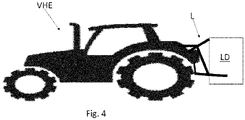
- an agricultural or work vehicle VHE equipped with a hydraulic lift L shown on figure 1 , the latter comprises two hydraulic cylinders Cs, Cd arranged to lift the same number of arms 2s, 2d of the hydraulic lift, with the arms interconnected by means of a stiffening bar CL.
- Each hydraulic cylinder comprises an expansion chamber and a hydraulic circuit HC comprising
- the control device EHR is arranged to control a flow of hydraulic oil from a source of hydraulic oil, indicated by the relative line having the label "Pressure”, towards both expansion chambers during the lifting of the arms and from the expansion chambers towards a recovery tank, indicated with the label “Tank” attributed to the relative line, during the lowering of the arms.
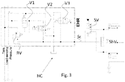
- Both expansion chambers are connected to the single and common hydraulic line Sc by means of a shuttle valve ShV and an ON/OFF valve SV arranged to bypass the shuttle valve during the lifting or lowering of the arms.
- the ON/OFF valve SV comprises a port operatively connected to a port of the control device EHR and at least one port operatively connected to both expansion chambers and to opposite ports of the shuttle valve ShV.
- the ON/OF valve SV is arranged to simultaneously connect both expansion chambers of both cylinders to the pressure source to effect lifting/lowering of the load.
- the ON/OFF valve is preferably controlled by the Load sensing signal LS which controls the valves V1 and V2.
- valve V2 when the valve V2 is controlled to command the lifting of the load and therefore the pressurization of the cylinder chambers, it generates a positive signal ("High") on the Load sensing line. This causes the valve SV to switch to open and therefore pressurizing the cylinder chambers.
- This solution is particularly advantageous because it allows to keep the control system of the hydraulic cylinders completely hydraulic, that is, without the aid of electrical control lines.
- control device EHR is controlled by a pressure signal
- SV valve is controlled by an electrical signal
- the entire EHR device, hydraulically controlled can be converted into an electro-hydraulic device, i.e. electrically controlled and with it the valve SV added to the known control device EHR.
- control device EHR preferably comprises an overpressure valve RV arranged to connect said single hydraulic Sc with said recovery Tank.
- the ON/OFF valve SV and the control device EHR are operationally controlled by means of a common control line (Load sensing).
- the hydraulic lift L preferably comprises a pair of articulated quadrilaterals, each comprising a lower arm 1s, 1d having a first end hinged to a vehicle frame, an upper connecting rod 2s, 2d having a first end hinged to the vehicle frame, a connecting rod 3s, 3d hinged with its opposite ends to the lower arm and to the lower connecting rod and each of said two hydraulic cylinders Cs, Cd is arranged to act between a part of the vehicle frame and an intermediate point of the upper connecting rod, so that an extension of the actuator brings the upper connecting rod to raise the opposite end to that hinged to the vehicle frame.
- the present invention relates to a method which provides a first step of operatively interconnecting the expansion chambers only when simultaneously connected with the source of hydraulic oil or with the recovery tank and a second step of mutually disconnecting them when the lift is in stationary conditions.
Landscapes
- Life Sciences & Earth Sciences (AREA)
- Zoology (AREA)
- Engineering & Computer Science (AREA)
- Mechanical Engineering (AREA)
- Soil Sciences (AREA)
- Environmental Sciences (AREA)
- Fluid-Pressure Circuits (AREA)
- Lifting Devices For Agricultural Implements (AREA)
Abstract
Description
- The present invention relates to the field of agricultural or work vehicles equipped with a hydraulic lift for lifting loads or devices to be associated to the vehicle itself.
- Agricultural or work vehicles are equipped with a hydraulic lift located at the rear of the vehicle. ISO730 standardizes the mechanical and dimensional characteristics of these lifting systems.
-
Figures 1a and 1b show an example of hydraulic lift L according to the known art, whilefigure 2 shows a hydraulic control circuit of the lift according to the known art. -
Figure 1a shows the lift from the side. It is generally formed by a 3-point articulation comprising: - two
lower levers - two
upper arms - two connecting
rods - a connecting rod or "third point" 4 directly hinged to the vehicle frame (not shown) as well as the lower levers and upper arms.
- Each upper arm (4s and 4d) is moved by a hydraulic cylinder, generally double-action type, Cs, Cd which acts between a part of the vehicle frame and an intermediate point of the upper arm, so that an extension of the actuator brings the upper arm to lift the opposite end to the one hinged to the vehicle frame. This opposite end, being hinged to the
rod - Since the connecting rod 4 is hinged for one end to the vehicle frame and for the opposite end to the load frame LD (generally an agricultural tool or transport system), the connection rod is also induced to rise following its own trajectory to the load.
- It is clear that the load connected to the lift is shown schematically.
- Between the upper right connecting
rod 2d and the upper left connectingrod 2s there is a stiffening bar CL which has the purpose of interconnecting the right rod with the left one. -
Figure 2 shows a hydraulic control circuit of the hydraulic cylinders Cs, Cd. - For convenience, only the chambers of the hydraulic cylinders intended to expand when it is necessary to lift a load are taken into consideration, while any opposite chambers are connected to the hydraulic circuit in a per se known manner.
- Since these chambers tend to extend their respective hydraulic actuators, they are hereinafter referred to as "expansion chambers".
- The expansion chamber of each cylinder is connected to a common source of supply of hydraulic oil, wherein control valves V1, V2, V3 are shown in the EHR block, connecting the pressure source with the expansion chambers of the hydraulic cylinders Cs, CD.
- The first valve V1 is a local compensator, which regulates the flow rate on the supply branch according to the Load Sensing LS signal of the lift and the pressure on the supply branch itself.
- The second valve V2 controls, with a proportional regulation, the lifting of the load LD.
- The third valve V3 proportionally controls the lowering of the load, connecting the hydraulic cylinders to the exhaust. The overpressure valve RV has the task of releasing any hydraulic oil into the recovery tank T in case of exceeding a predetermined threshold pressure on the hydraulic line L which interconnects the EHR block with the expansion chambers of the hydraulic cylinders.
- As a whole, the control block EHR has the task of controlling the flow from the source of hydraulic oil such as a hydraulic pump to the expansion chambers and that of controlling the flow of hydraulic oil from the expansion chambers to the recovery tank (Tank) of hydraulic oil, from which the hydraulic pump draws the oil to send it back into circulation.
- It can be seen that the expansion chambers of the cylinders are connected with the EHR control block by means of a single hydraulic line Sc, through which the hydraulic oil can pass in both directions depending on the lifting or lowering of the lift.
- When the load applied to the lift is arranged in such a way as to weigh in a different way on the hydraulic cylinders Cs and Cd, since the chambers of the same cylinders are interconnected, a displacement of hydraulic oil from one chamber to the other is determined which causes the cylinder to be less loaded to extend further. This unbalanced loading of the quadrilaterals and the distribution of hydraulic oil in the respective expansion chambers of the hydraulic cylinders is balanced by the stiffening bar CL. The set of 2s and 2d upper connecting rods and the stiffening bar therefore works as a torsion bar.
- In relation to the type of lift, a proportionally strong and heavy stiffening bar CL must be provided. All this entails an overall weighting of the vehicle and a greater cost of production of the hydraulic lift.
- This problem is particularly felt when the lifted load is asymmetrical with respect to the tractor axis, as happens with many attachments. In this case, asymmetrical loads are generated on the two sides of the lift, often with oscillating characteristics, during transport on rough terrain or while working of the soil, which must be fully absorbed by the stiffening bar.
- If not specifically excluded in the detailed description that follows, what is described in this chapter is to be considered as an integral part of the detailed description.
- The object of the present invention is to make the hydraulic lift less sensitive to a loading asymmetry of the quadrilaterals defining the hydraulic lift and of the respective hydraulic cylinders.
- The basic idea of the present invention is to modify the hydraulic circuit for feeding the expansion chambers of the hydraulic cylinders enslaved to the articulated quadrilaterals defining the hydraulic lift described above, so as to keep the expansion chambers interconnected during lifting, but to disconnect them from each other when the lift is in stationary conditions.
- More specifically, the idea is to connect the single hydraulic line with the expansion chambers by means of a shuttle valve, so that each of them is independently connected to the single connection line, so that in stationary conditions, the cylinder subject to the greatest load can communicate with the pressure relief valve without transferring hydraulic fluid to the expansion chamber of the other hydraulic cylinder.
- A spool valve is arranged to connect the single hydraulic line with the expansion chambers to bypass the shuttle valve.
- The dependent claims describe preferred variants of the invention, forming an integral part of this description.
- Further objects and advantages of the present invention will become clear from the following detailed description of an example of its embodiment (and its variants) and from the attached drawings given purely by way of non-limiting explanation, wherein:
-
Figures 1a and 1b show the side and front views respectively of an example of a hydraulic lift of the prior art object of the present invention; -
Figure 2 shows a hydraulic circuit, according to the known art, for controlling the hydraulic actuators of the lift of the previous figures; -
Figure 3 shows a modified hydraulic circuit according to the present invention for controlling the hydraulic lift according toFigures 1a and 1b ; -
Figure 4 shows an example of an agricultural or work vehicle associated with a hydraulic lift controlled by means of a hydraulic circuit according to the present invention. - The same reference numbers and letters in the figures identify the same elements or components or functions.
- For convenience and simplicity of understanding the invention, the same numbers and letters have been used for corresponding parts of the prior art diagrams and diagrams object of the present invention.
- It should also be noted that the terms "first", "second", "third", "upper", "lower" and the like can be used here to distinguish various elements. These terms do not imply a spatial, sequential or hierarchical order for the modified elements unless specifically indicated or inferred from the text.
- The elements and features illustrated in the various preferred embodiments, including the drawings, can be combined with each other without however departing from the scope of this application as described below.
- With reference to
figure 4 , an agricultural or work vehicle VHE is disclosed, equipped with a hydraulic lift L shown onfigure 1 , the latter comprises two hydraulic cylinders Cs, Cd arranged to lift the same number ofarms - a control device EHR and
- a single and common hydraulic line Sc arranged to connect the control device with both expansion chambers of the two hydraulic cylinders.
- The control device EHR is arranged to control a flow of hydraulic oil from a source of hydraulic oil, indicated by the relative line having the label "Pressure", towards both expansion chambers during the lifting of the arms and from the expansion chambers towards a recovery tank, indicated with the label "Tank" attributed to the relative line, during the lowering of the arms.
- Both expansion chambers are connected to the single and common hydraulic line Sc by means of a shuttle valve ShV and an ON/OFF valve SV arranged to bypass the shuttle valve during the lifting or lowering of the arms.
- The ON/OFF valve SV comprises a port operatively connected to a port of the control device EHR and at least one port operatively connected to both expansion chambers and to opposite ports of the shuttle valve ShV.
- Therefore, the ON/OF valve SV is arranged to simultaneously connect both expansion chambers of both cylinders to the pressure source to effect lifting/lowering of the load.
- The ON/OFF valve is preferably controlled by the Load sensing signal LS which controls the valves V1 and V2.
- In particular, when the valve V2 is controlled to command the lifting of the load and therefore the pressurization of the cylinder chambers, it generates a positive signal ("High") on the Load sensing line. This causes the valve SV to switch to open and therefore pressurizing the cylinder chambers.
- This solution is particularly advantageous because it allows to keep the control system of the hydraulic cylinders completely hydraulic, that is, without the aid of electrical control lines.
- However, a mixed solution can be envisaged in which the control device EHR is controlled by a pressure signal, while the SV valve is controlled by an electrical signal. Alternatively, the entire EHR device, hydraulically controlled, can be converted into an electro-hydraulic device, i.e. electrically controlled and with it the valve SV added to the known control device EHR.
- Furthermore, the control device EHR preferably comprises an overpressure valve RV arranged to connect said single hydraulic Sc with said recovery Tank.
- Preferably, the ON/OFF valve SV and the control device EHR are operationally controlled by means of a common control line (Load sensing).
- The "State of the art" paragraph forms an integral part of this detailed description and therefore, the hydraulic lift L preferably comprises a pair of articulated quadrilaterals, each comprising a
lower arm rod rod - In general terms, the present invention relates to a method which provides a first step of operatively interconnecting the expansion chambers only when simultaneously connected with the source of hydraulic oil or with the recovery tank and a second step of mutually disconnecting them when the lift is in stationary conditions.
- For the purposes of the present invention, by "stationary conditions" it is meant that the lift is stationary remaining still in any of the admissible positions. Implementation variants of the described non-limiting example are possible, without however departing from the scope of the present invention, including all the equivalent embodiments for a person skilled in the art, to the content of the claims.
- From the above description, the person skilled in the art is able to realize the object of the invention without introducing further construction details.
Claims (8)
- Agricultural or work vehicle (VHE) equipped with a hydraulic lift (L) comprising- two hydraulic cylinders (Cs, Cd) arranged to lift the same number of arms (2s, 2d) of the hydraulic lift, with the arms interconnected by means of a stiffening bar (CL), each hydraulic cylinder comprising an expansion chamber,- a hydraulic circuit (HC) comprising. a control device (EHR) and. a single and common hydraulic line (Sc) arranged to connect the control device with both expansion chambers of the two hydraulic cylinders,wherein the control device (EHR) is arranged to control a flow of hydraulic oil from a hydraulic oil source (Pressure) to both expansion chambers during the lifting of the arms and from the expansion chambers to a recovery tank (Tank) during lowering the arms,and wherein both expansion chambers are connected to said single and common hydraulic line by means of a shuttle valve (ShV) and an ON/OFF valve (SV) arranged to bypass the shuttle valve during the lifting or lowering procedure of the arms.
- Vehicle according to claim 1, wherein said ON/OFF valve comprises a door operatively connected with a door of the control device (EHR) and at least one door operatively connected with both expansion chambers and with opposite doors of the shuttle valve (ShV).
- Vehicle according to any one of the preceding claims wherein said control device (EHR) comprises an overpressure valve (RV) arranged to connect said single hydraulic (Sc) with said recovery tank (Tank).
- Vehicle according to any one of the preceding claims, wherein said ON/OFF valve (SV) and said control device (EHR) are operationally controlled by means of a common hydraulic control line (Load sensing), so that the entire control system is purely hydraulic.
- Vehicle according to any one of the preceding claims wherein said hydraulic lift (L) comprises a pair of articulated quadrilaterals, each comprising two lower levers (1s, 1d) having a first end hinged to a vehicle frame, two upper arms (2s, 2d) having a first end hinged to the vehicle frame, two connecting tie rods (3s, 3d) hinged with their opposite ends to the upper arm and to the lower lever and each of said two hydraulic cylinders (Cs, Cd) is arranged to act between a part of the vehicle frame and an intermediate point of the corresponding upper arm, so that an extension of the actuator brings the upper arm to raise the opposite end to the one hinged to the vehicle frame.
- Control method of a hydraulic circuit (HC) for controlling a hydraulic lift (L) of an agricultural or work vehicle (VHE) wherein the hydraulic lift (L) comprising two hydraulic cylinders (Cs, Cd) arranged for raise as many arms (2s, 2d) of the hydraulic lift, with the arms interconnected by means of a stiffening bar (CL), each hydraulic cylinder including an expansion chamber, and wherein the hydraulic circuit (HC) comprises. a control device (EHR) ed. a single and common hydraulic line (Sc) arranged to connect the control device with both expansion chambers of the two hydraulic cylinders,wherein the control device (EHR) is arranged to control a flow of hydraulic oil from a hydraulic oil source (Pressure) to both expansion chambers during the lifting of the arms and from the expansion chambers to a recovery tank (Tank) during lowering the arms,the method comprising a first step of operatively interconnecting said expansion chambers only when simultaneously connected with said source of hydraulic oil or with said recovery tank and a second step of mutually disconnecting them when the lift is in stationary conditions.
- Method according to claim 6, wherein said second step comprises connecting both expansion chambers with said recovery tank independently of each other.
- Method according to claim 7, wherein said independent connection of the expansion chambers with the recovery tank is made by means of a shuttle valve.
Applications Claiming Priority (1)
| Application Number | Priority Date | Filing Date | Title |
|---|---|---|---|
| IT102021000002648A IT202100002648A1 (en) | 2021-02-05 | 2021-02-05 | AGRICULTURAL OR WORKING VEHICLE EQUIPPED WITH A HYDRAULIC LIFT |
Publications (2)
| Publication Number | Publication Date |
|---|---|
| EP4039072A1 true EP4039072A1 (en) | 2022-08-10 |
| EP4039072B1 EP4039072B1 (en) | 2023-12-13 |
Family
ID=75439376
Family Applications (1)
| Application Number | Title | Priority Date | Filing Date |
|---|---|---|---|
| EP22155207.8A Active EP4039072B1 (en) | 2021-02-05 | 2022-02-04 | Agricultural or work vehicle equipped with a hydraulic lift |
Country Status (2)
| Country | Link |
|---|---|
| EP (1) | EP4039072B1 (en) |
| IT (1) | IT202100002648A1 (en) |
Citations (5)
| Publication number | Priority date | Publication date | Assignee | Title |
|---|---|---|---|---|
| FR2139153A1 (en) * | 1971-05-27 | 1973-01-05 | Fiat Spa | |
| JPH09133102A (en) * | 1995-11-10 | 1997-05-20 | Kubota Corp | Hydraulic circuit for lifting work equipment |
| EP2765844A1 (en) * | 2011-10-13 | 2014-08-20 | AGCO International GmbH | Vehicle control system |
| EP2884118A1 (en) * | 2013-10-30 | 2015-06-17 | AGCO International GmbH | Hydraulic supply system |
| EP2889515A1 (en) * | 2013-12-23 | 2015-07-01 | AGCO International GmbH | Vehicle control system |
-
2021
- 2021-02-05 IT IT102021000002648A patent/IT202100002648A1/en unknown
-
2022
- 2022-02-04 EP EP22155207.8A patent/EP4039072B1/en active Active
Patent Citations (5)
| Publication number | Priority date | Publication date | Assignee | Title |
|---|---|---|---|---|
| FR2139153A1 (en) * | 1971-05-27 | 1973-01-05 | Fiat Spa | |
| JPH09133102A (en) * | 1995-11-10 | 1997-05-20 | Kubota Corp | Hydraulic circuit for lifting work equipment |
| EP2765844A1 (en) * | 2011-10-13 | 2014-08-20 | AGCO International GmbH | Vehicle control system |
| EP2884118A1 (en) * | 2013-10-30 | 2015-06-17 | AGCO International GmbH | Hydraulic supply system |
| EP2889515A1 (en) * | 2013-12-23 | 2015-07-01 | AGCO International GmbH | Vehicle control system |
Also Published As
| Publication number | Publication date |
|---|---|
| IT202100002648A1 (en) | 2022-08-05 |
| EP4039072B1 (en) | 2023-12-13 |
Similar Documents
| Publication | Publication Date | Title |
|---|---|---|
| KR100228810B1 (en) | Hydraulics for Construction Equipment | |
| US9303632B2 (en) | Energy recovery control circuit and work machine | |
| US7752842B2 (en) | Circuit for controlling a double-action hydraulic drive cylinder | |
| US5490384A (en) | Hydraulic flow priority system | |
| US6951103B2 (en) | Hydraulic control arrangement for a mobile operating machine | |
| WO2005031172A1 (en) | Hydraulic control device of industrial machinery | |
| US11339041B2 (en) | Power lift | |
| JPWO2001055603A1 (en) | Hydraulic drive unit | |
| US20150361998A1 (en) | Hydraulic system with energy recovery | |
| EP1403102B1 (en) | Hitch device for attaching farm implements to a tractor and associated hydraulic circuit | |
| US6161467A (en) | Fluid control system with regeneration | |
| US7059237B2 (en) | Multiple-directional switching valve | |
| WO1999035407A1 (en) | Control arrangement for a hydraulic motor | |
| EP4039072B1 (en) | Agricultural or work vehicle equipped with a hydraulic lift | |
| US6761027B2 (en) | Pressure-compensated hydraulic circuit with regeneration | |
| US12320368B2 (en) | Ride control for work machines | |
| US20050098329A1 (en) | Control system for a three point implement hitch assembly | |
| US20030115864A1 (en) | Hydraulic power boost system for a work vehicle | |
| WO2023006238A1 (en) | Ride control for work machines | |
| US20230354733A1 (en) | Hydraulic adjustment device | |
| CA1083089A (en) | Implement circuit for motor with slow and fast dump | |
| US7117670B2 (en) | Control device | |
| WO2023188593A1 (en) | Construction machine | |
| US20200385952A1 (en) | An implement attachment device | |
| GB2055977A (en) | Hydraulic control systems |
Legal Events
| Date | Code | Title | Description |
|---|---|---|---|
| PUAI | Public reference made under article 153(3) epc to a published international application that has entered the european phase |
Free format text: ORIGINAL CODE: 0009012 |
|
| STAA | Information on the status of an ep patent application or granted ep patent |
Free format text: STATUS: THE APPLICATION HAS BEEN PUBLISHED |
|
| AK | Designated contracting states |
Kind code of ref document: A1 Designated state(s): AL AT BE BG CH CY CZ DE DK EE ES FI FR GB GR HR HU IE IS IT LI LT LU LV MC MK MT NL NO PL PT RO RS SE SI SK SM TR |
|
| STAA | Information on the status of an ep patent application or granted ep patent |
Free format text: STATUS: REQUEST FOR EXAMINATION WAS MADE |
|
| 17P | Request for examination filed |
Effective date: 20230210 |
|
| RBV | Designated contracting states (corrected) |
Designated state(s): AL AT BE BG CH CY CZ DE DK EE ES FI FR GB GR HR HU IE IS IT LI LT LU LV MC MK MT NL NO PL PT RO RS SE SI SK SM TR |
|
| GRAP | Despatch of communication of intention to grant a patent |
Free format text: ORIGINAL CODE: EPIDOSNIGR1 |
|
| RAP3 | Party data changed (applicant data changed or rights of an application transferred) |
Owner name: CNH INDUSTRIAL ITALIA S.P.A. |
|
| STAA | Information on the status of an ep patent application or granted ep patent |
Free format text: STATUS: GRANT OF PATENT IS INTENDED |
|
| RIC1 | Information provided on ipc code assigned before grant |
Ipc: F15B 11/22 20060101ALN20230530BHEP Ipc: A01B 59/043 20060101AFI20230530BHEP |
|
| INTG | Intention to grant announced |
Effective date: 20230629 |
|
| GRAS | Grant fee paid |
Free format text: ORIGINAL CODE: EPIDOSNIGR3 |
|
| GRAA | (expected) grant |
Free format text: ORIGINAL CODE: 0009210 |
|
| STAA | Information on the status of an ep patent application or granted ep patent |
Free format text: STATUS: THE PATENT HAS BEEN GRANTED |
|
| AK | Designated contracting states |
Kind code of ref document: B1 Designated state(s): AL AT BE BG CH CY CZ DE DK EE ES FI FR GB GR HR HU IE IS IT LI LT LU LV MC MK MT NL NO PL PT RO RS SE SI SK SM TR |
|
| REG | Reference to a national code |
Ref country code: GB Ref legal event code: FG4D |
|
| REG | Reference to a national code |
Ref country code: CH Ref legal event code: EP |
|
| REG | Reference to a national code |
Ref country code: DE Ref legal event code: R096 Ref document number: 602022001242 Country of ref document: DE |
|
| REG | Reference to a national code |
Ref country code: IE Ref legal event code: FG4D |
|
| PG25 | Lapsed in a contracting state [announced via postgrant information from national office to epo] |
Ref country code: GR Free format text: LAPSE BECAUSE OF FAILURE TO SUBMIT A TRANSLATION OF THE DESCRIPTION OR TO PAY THE FEE WITHIN THE PRESCRIBED TIME-LIMIT Effective date: 20240314 |
|
| REG | Reference to a national code |
Ref country code: LT Ref legal event code: MG9D |
|
| PG25 | Lapsed in a contracting state [announced via postgrant information from national office to epo] |
Ref country code: LT Free format text: LAPSE BECAUSE OF FAILURE TO SUBMIT A TRANSLATION OF THE DESCRIPTION OR TO PAY THE FEE WITHIN THE PRESCRIBED TIME-LIMIT Effective date: 20231213 |
|
| REG | Reference to a national code |
Ref country code: NL Ref legal event code: MP Effective date: 20231213 |
|
| PG25 | Lapsed in a contracting state [announced via postgrant information from national office to epo] |
Ref country code: ES Free format text: LAPSE BECAUSE OF FAILURE TO SUBMIT A TRANSLATION OF THE DESCRIPTION OR TO PAY THE FEE WITHIN THE PRESCRIBED TIME-LIMIT Effective date: 20231213 |
|
| PG25 | Lapsed in a contracting state [announced via postgrant information from national office to epo] |
Ref country code: LT Free format text: LAPSE BECAUSE OF FAILURE TO SUBMIT A TRANSLATION OF THE DESCRIPTION OR TO PAY THE FEE WITHIN THE PRESCRIBED TIME-LIMIT Effective date: 20231213 Ref country code: GR Free format text: LAPSE BECAUSE OF FAILURE TO SUBMIT A TRANSLATION OF THE DESCRIPTION OR TO PAY THE FEE WITHIN THE PRESCRIBED TIME-LIMIT Effective date: 20240314 Ref country code: ES Free format text: LAPSE BECAUSE OF FAILURE TO SUBMIT A TRANSLATION OF THE DESCRIPTION OR TO PAY THE FEE WITHIN THE PRESCRIBED TIME-LIMIT Effective date: 20231213 Ref country code: BG Free format text: LAPSE BECAUSE OF FAILURE TO SUBMIT A TRANSLATION OF THE DESCRIPTION OR TO PAY THE FEE WITHIN THE PRESCRIBED TIME-LIMIT Effective date: 20240313 |
|
| REG | Reference to a national code |
Ref country code: AT Ref legal event code: MK05 Ref document number: 1639609 Country of ref document: AT Kind code of ref document: T Effective date: 20231213 |
|
| PG25 | Lapsed in a contracting state [announced via postgrant information from national office to epo] |
Ref country code: NL Free format text: LAPSE BECAUSE OF FAILURE TO SUBMIT A TRANSLATION OF THE DESCRIPTION OR TO PAY THE FEE WITHIN THE PRESCRIBED TIME-LIMIT Effective date: 20231213 |
|
| PG25 | Lapsed in a contracting state [announced via postgrant information from national office to epo] |
Ref country code: SE Free format text: LAPSE BECAUSE OF FAILURE TO SUBMIT A TRANSLATION OF THE DESCRIPTION OR TO PAY THE FEE WITHIN THE PRESCRIBED TIME-LIMIT Effective date: 20231213 Ref country code: RS Free format text: LAPSE BECAUSE OF FAILURE TO SUBMIT A TRANSLATION OF THE DESCRIPTION OR TO PAY THE FEE WITHIN THE PRESCRIBED TIME-LIMIT Effective date: 20231213 Ref country code: NO Free format text: LAPSE BECAUSE OF FAILURE TO SUBMIT A TRANSLATION OF THE DESCRIPTION OR TO PAY THE FEE WITHIN THE PRESCRIBED TIME-LIMIT Effective date: 20240313 Ref country code: NL Free format text: LAPSE BECAUSE OF FAILURE TO SUBMIT A TRANSLATION OF THE DESCRIPTION OR TO PAY THE FEE WITHIN THE PRESCRIBED TIME-LIMIT Effective date: 20231213 Ref country code: LV Free format text: LAPSE BECAUSE OF FAILURE TO SUBMIT A TRANSLATION OF THE DESCRIPTION OR TO PAY THE FEE WITHIN THE PRESCRIBED TIME-LIMIT Effective date: 20231213 Ref country code: HR Free format text: LAPSE BECAUSE OF FAILURE TO SUBMIT A TRANSLATION OF THE DESCRIPTION OR TO PAY THE FEE WITHIN THE PRESCRIBED TIME-LIMIT Effective date: 20231213 |
|
| PG25 | Lapsed in a contracting state [announced via postgrant information from national office to epo] |
Ref country code: IS Free format text: LAPSE BECAUSE OF FAILURE TO SUBMIT A TRANSLATION OF THE DESCRIPTION OR TO PAY THE FEE WITHIN THE PRESCRIBED TIME-LIMIT Effective date: 20240413 |
|
| PG25 | Lapsed in a contracting state [announced via postgrant information from national office to epo] |
Ref country code: CZ Free format text: LAPSE BECAUSE OF FAILURE TO SUBMIT A TRANSLATION OF THE DESCRIPTION OR TO PAY THE FEE WITHIN THE PRESCRIBED TIME-LIMIT Effective date: 20231213 Ref country code: AT Free format text: LAPSE BECAUSE OF FAILURE TO SUBMIT A TRANSLATION OF THE DESCRIPTION OR TO PAY THE FEE WITHIN THE PRESCRIBED TIME-LIMIT Effective date: 20231213 |
|
| PG25 | Lapsed in a contracting state [announced via postgrant information from national office to epo] |
Ref country code: SK Free format text: LAPSE BECAUSE OF FAILURE TO SUBMIT A TRANSLATION OF THE DESCRIPTION OR TO PAY THE FEE WITHIN THE PRESCRIBED TIME-LIMIT Effective date: 20231213 |
|
| PG25 | Lapsed in a contracting state [announced via postgrant information from national office to epo] |
Ref country code: SM Free format text: LAPSE BECAUSE OF FAILURE TO SUBMIT A TRANSLATION OF THE DESCRIPTION OR TO PAY THE FEE WITHIN THE PRESCRIBED TIME-LIMIT Effective date: 20231213 Ref country code: SK Free format text: LAPSE BECAUSE OF FAILURE TO SUBMIT A TRANSLATION OF THE DESCRIPTION OR TO PAY THE FEE WITHIN THE PRESCRIBED TIME-LIMIT Effective date: 20231213 Ref country code: RO Free format text: LAPSE BECAUSE OF FAILURE TO SUBMIT A TRANSLATION OF THE DESCRIPTION OR TO PAY THE FEE WITHIN THE PRESCRIBED TIME-LIMIT Effective date: 20231213 Ref country code: IS Free format text: LAPSE BECAUSE OF FAILURE TO SUBMIT A TRANSLATION OF THE DESCRIPTION OR TO PAY THE FEE WITHIN THE PRESCRIBED TIME-LIMIT Effective date: 20240413 Ref country code: EE Free format text: LAPSE BECAUSE OF FAILURE TO SUBMIT A TRANSLATION OF THE DESCRIPTION OR TO PAY THE FEE WITHIN THE PRESCRIBED TIME-LIMIT Effective date: 20231213 Ref country code: CZ Free format text: LAPSE BECAUSE OF FAILURE TO SUBMIT A TRANSLATION OF THE DESCRIPTION OR TO PAY THE FEE WITHIN THE PRESCRIBED TIME-LIMIT Effective date: 20231213 Ref country code: AT Free format text: LAPSE BECAUSE OF FAILURE TO SUBMIT A TRANSLATION OF THE DESCRIPTION OR TO PAY THE FEE WITHIN THE PRESCRIBED TIME-LIMIT Effective date: 20231213 |
|
| PG25 | Lapsed in a contracting state [announced via postgrant information from national office to epo] |
Ref country code: PL Free format text: LAPSE BECAUSE OF FAILURE TO SUBMIT A TRANSLATION OF THE DESCRIPTION OR TO PAY THE FEE WITHIN THE PRESCRIBED TIME-LIMIT Effective date: 20231213 Ref country code: PT Free format text: LAPSE BECAUSE OF FAILURE TO SUBMIT A TRANSLATION OF THE DESCRIPTION OR TO PAY THE FEE WITHIN THE PRESCRIBED TIME-LIMIT Effective date: 20240415 |
|
| PG25 | Lapsed in a contracting state [announced via postgrant information from national office to epo] |
Ref country code: PT Free format text: LAPSE BECAUSE OF FAILURE TO SUBMIT A TRANSLATION OF THE DESCRIPTION OR TO PAY THE FEE WITHIN THE PRESCRIBED TIME-LIMIT Effective date: 20240415 Ref country code: PL Free format text: LAPSE BECAUSE OF FAILURE TO SUBMIT A TRANSLATION OF THE DESCRIPTION OR TO PAY THE FEE WITHIN THE PRESCRIBED TIME-LIMIT Effective date: 20231213 |
|
| REG | Reference to a national code |
Ref country code: DE Ref legal event code: R097 Ref document number: 602022001242 Country of ref document: DE |
|
| PG25 | Lapsed in a contracting state [announced via postgrant information from national office to epo] |
Ref country code: MC Free format text: LAPSE BECAUSE OF FAILURE TO SUBMIT A TRANSLATION OF THE DESCRIPTION OR TO PAY THE FEE WITHIN THE PRESCRIBED TIME-LIMIT Effective date: 20231213 |
|
| PG25 | Lapsed in a contracting state [announced via postgrant information from national office to epo] |
Ref country code: DK Free format text: LAPSE BECAUSE OF FAILURE TO SUBMIT A TRANSLATION OF THE DESCRIPTION OR TO PAY THE FEE WITHIN THE PRESCRIBED TIME-LIMIT Effective date: 20231213 |
|
| PG25 | Lapsed in a contracting state [announced via postgrant information from national office to epo] |
Ref country code: LU Free format text: LAPSE BECAUSE OF NON-PAYMENT OF DUE FEES Effective date: 20240204 |
|
| PLBE | No opposition filed within time limit |
Free format text: ORIGINAL CODE: 0009261 |
|
| STAA | Information on the status of an ep patent application or granted ep patent |
Free format text: STATUS: NO OPPOSITION FILED WITHIN TIME LIMIT |
|
| PG25 | Lapsed in a contracting state [announced via postgrant information from national office to epo] |
Ref country code: SI Free format text: LAPSE BECAUSE OF FAILURE TO SUBMIT A TRANSLATION OF THE DESCRIPTION OR TO PAY THE FEE WITHIN THE PRESCRIBED TIME-LIMIT Effective date: 20231213 |
|
| PG25 | Lapsed in a contracting state [announced via postgrant information from national office to epo] |
Ref country code: SI Free format text: LAPSE BECAUSE OF FAILURE TO SUBMIT A TRANSLATION OF THE DESCRIPTION OR TO PAY THE FEE WITHIN THE PRESCRIBED TIME-LIMIT Effective date: 20231213 Ref country code: LU Free format text: LAPSE BECAUSE OF NON-PAYMENT OF DUE FEES Effective date: 20240204 Ref country code: DK Free format text: LAPSE BECAUSE OF FAILURE TO SUBMIT A TRANSLATION OF THE DESCRIPTION OR TO PAY THE FEE WITHIN THE PRESCRIBED TIME-LIMIT Effective date: 20231213 |
|
| 26N | No opposition filed |
Effective date: 20240916 |
|
| REG | Reference to a national code |
Ref country code: BE Ref legal event code: MM Effective date: 20240229 |
|
| PG25 | Lapsed in a contracting state [announced via postgrant information from national office to epo] |
Ref country code: BE Free format text: LAPSE BECAUSE OF NON-PAYMENT OF DUE FEES Effective date: 20240229 |
|
| PG25 | Lapsed in a contracting state [announced via postgrant information from national office to epo] |
Ref country code: IE Free format text: LAPSE BECAUSE OF NON-PAYMENT OF DUE FEES Effective date: 20240204 |
|
| PG25 | Lapsed in a contracting state [announced via postgrant information from national office to epo] |
Ref country code: IE Free format text: LAPSE BECAUSE OF NON-PAYMENT OF DUE FEES Effective date: 20240204 Ref country code: BE Free format text: LAPSE BECAUSE OF NON-PAYMENT OF DUE FEES Effective date: 20240229 |
|
| PG25 | Lapsed in a contracting state [announced via postgrant information from national office to epo] |
Ref country code: CY Free format text: LAPSE BECAUSE OF FAILURE TO SUBMIT A TRANSLATION OF THE DESCRIPTION OR TO PAY THE FEE WITHIN THE PRESCRIBED TIME-LIMIT; INVALID AB INITIO Effective date: 20220204 |
|
| REG | Reference to a national code |
Ref country code: CH Ref legal event code: PL |
|
| PG25 | Lapsed in a contracting state [announced via postgrant information from national office to epo] |
Ref country code: FI Free format text: LAPSE BECAUSE OF FAILURE TO SUBMIT A TRANSLATION OF THE DESCRIPTION OR TO PAY THE FEE WITHIN THE PRESCRIBED TIME-LIMIT Effective date: 20231213 |
|
| PG25 | Lapsed in a contracting state [announced via postgrant information from national office to epo] |
Ref country code: CH Free format text: LAPSE BECAUSE OF NON-PAYMENT OF DUE FEES Effective date: 20250228 |
|
| PG25 | Lapsed in a contracting state [announced via postgrant information from national office to epo] |
Ref country code: TR Free format text: LAPSE BECAUSE OF FAILURE TO SUBMIT A TRANSLATION OF THE DESCRIPTION OR TO PAY THE FEE WITHIN THE PRESCRIBED TIME-LIMIT Effective date: 20231213 |
|
| PGFP | Annual fee paid to national office [announced via postgrant information from national office to epo] |
Ref country code: GB Payment date: 20260223 Year of fee payment: 5 |
|
| PGFP | Annual fee paid to national office [announced via postgrant information from national office to epo] |
Ref country code: DE Payment date: 20260220 Year of fee payment: 5 |
|
| PGFP | Annual fee paid to national office [announced via postgrant information from national office to epo] |
Ref country code: IT Payment date: 20260220 Year of fee payment: 5 |
|
| PGFP | Annual fee paid to national office [announced via postgrant information from national office to epo] |
Ref country code: FR Payment date: 20260227 Year of fee payment: 5 |
|
| PG25 | Lapsed in a contracting state [announced via postgrant information from national office to epo] |
Ref country code: CH Free format text: THE PATENT HAS BEEN ANNULLED BY A DECISION OF A NATIONAL AUTHORITY Effective date: 20250228 |
|
| PG25 | Lapsed in a contracting state [announced via postgrant information from national office to epo] |
Ref country code: HU Free format text: LAPSE BECAUSE OF FAILURE TO SUBMIT A TRANSLATION OF THE DESCRIPTION OR TO PAY THE FEE WITHIN THE PRESCRIBED TIME-LIMIT; INVALID AB INITIO Effective date: 20220204 |