EP4038676B1 - A method for bonding components of a fuel cell - Google Patents
A method for bonding components of a fuel cell Download PDFInfo
- Publication number
- EP4038676B1 EP4038676B1 EP20731457.6A EP20731457A EP4038676B1 EP 4038676 B1 EP4038676 B1 EP 4038676B1 EP 20731457 A EP20731457 A EP 20731457A EP 4038676 B1 EP4038676 B1 EP 4038676B1
- Authority
- EP
- European Patent Office
- Prior art keywords
- adhesive
- frame
- components
- membrane
- electromagnetic radiation
- Prior art date
- Legal status (The legal status is an assumption and is not a legal conclusion. Google has not performed a legal analysis and makes no representation as to the accuracy of the status listed.)
- Active
Links
Images


Classifications
-
- H—ELECTRICITY
- H01—ELECTRIC ELEMENTS
- H01M—PROCESSES OR MEANS, e.g. BATTERIES, FOR THE DIRECT CONVERSION OF CHEMICAL ENERGY INTO ELECTRICAL ENERGY
- H01M8/00—Fuel cells; Manufacture thereof
- H01M8/02—Details
- H01M8/0271—Sealing or supporting means around electrodes, matrices or membranes
- H01M8/0286—Processes for forming seals
-
- C—CHEMISTRY; METALLURGY
- C09—DYES; PAINTS; POLISHES; NATURAL RESINS; ADHESIVES; COMPOSITIONS NOT OTHERWISE PROVIDED FOR; APPLICATIONS OF MATERIALS NOT OTHERWISE PROVIDED FOR
- C09J—ADHESIVES; NON-MECHANICAL ASPECTS OF ADHESIVE PROCESSES IN GENERAL; ADHESIVE PROCESSES NOT PROVIDED FOR ELSEWHERE; USE OF MATERIALS AS ADHESIVES
- C09J163/00—Adhesives based on epoxy resins; Adhesives based on derivatives of epoxy resins
-
- C—CHEMISTRY; METALLURGY
- C09—DYES; PAINTS; POLISHES; NATURAL RESINS; ADHESIVES; COMPOSITIONS NOT OTHERWISE PROVIDED FOR; APPLICATIONS OF MATERIALS NOT OTHERWISE PROVIDED FOR
- C09J—ADHESIVES; NON-MECHANICAL ASPECTS OF ADHESIVE PROCESSES IN GENERAL; ADHESIVE PROCESSES NOT PROVIDED FOR ELSEWHERE; USE OF MATERIALS AS ADHESIVES
- C09J5/00—Adhesive processes in general; Adhesive processes not provided for elsewhere, e.g. relating to primers
- C09J5/06—Adhesive processes in general; Adhesive processes not provided for elsewhere, e.g. relating to primers involving heating of the applied adhesive
-
- H—ELECTRICITY
- H01—ELECTRIC ELEMENTS
- H01M—PROCESSES OR MEANS, e.g. BATTERIES, FOR THE DIRECT CONVERSION OF CHEMICAL ENERGY INTO ELECTRICAL ENERGY
- H01M8/00—Fuel cells; Manufacture thereof
- H01M8/02—Details
- H01M8/0202—Collectors; Separators, e.g. bipolar separators; Interconnectors
- H01M8/0267—Collectors; Separators, e.g. bipolar separators; Interconnectors having heating or cooling means, e.g. heaters or coolant flow channels
-
- H—ELECTRICITY
- H01—ELECTRIC ELEMENTS
- H01M—PROCESSES OR MEANS, e.g. BATTERIES, FOR THE DIRECT CONVERSION OF CHEMICAL ENERGY INTO ELECTRICAL ENERGY
- H01M8/00—Fuel cells; Manufacture thereof
- H01M8/02—Details
- H01M8/0271—Sealing or supporting means around electrodes, matrices or membranes
- H01M8/0273—Sealing or supporting means around electrodes, matrices or membranes with sealing or supporting means in the form of a frame
-
- H—ELECTRICITY
- H01—ELECTRIC ELEMENTS
- H01M—PROCESSES OR MEANS, e.g. BATTERIES, FOR THE DIRECT CONVERSION OF CHEMICAL ENERGY INTO ELECTRICAL ENERGY
- H01M8/00—Fuel cells; Manufacture thereof
- H01M8/02—Details
- H01M8/0271—Sealing or supporting means around electrodes, matrices or membranes
- H01M8/028—Sealing means characterised by their material
- H01M8/0284—Organic resins; Organic polymers
-
- H—ELECTRICITY
- H01—ELECTRIC ELEMENTS
- H01M—PROCESSES OR MEANS, e.g. BATTERIES, FOR THE DIRECT CONVERSION OF CHEMICAL ENERGY INTO ELECTRICAL ENERGY
- H01M8/00—Fuel cells; Manufacture thereof
- H01M8/10—Fuel cells with solid electrolytes
- H01M8/1004—Fuel cells with solid electrolytes characterised by membrane-electrode assemblies [MEA]
-
- C—CHEMISTRY; METALLURGY
- C09—DYES; PAINTS; POLISHES; NATURAL RESINS; ADHESIVES; COMPOSITIONS NOT OTHERWISE PROVIDED FOR; APPLICATIONS OF MATERIALS NOT OTHERWISE PROVIDED FOR
- C09J—ADHESIVES; NON-MECHANICAL ASPECTS OF ADHESIVE PROCESSES IN GENERAL; ADHESIVE PROCESSES NOT PROVIDED FOR ELSEWHERE; USE OF MATERIALS AS ADHESIVES
- C09J2203/00—Applications of adhesives in processes or use of adhesives in the form of films or foils
- C09J2203/33—Applications of adhesives in processes or use of adhesives in the form of films or foils for batteries or fuel cells
-
- C—CHEMISTRY; METALLURGY
- C09—DYES; PAINTS; POLISHES; NATURAL RESINS; ADHESIVES; COMPOSITIONS NOT OTHERWISE PROVIDED FOR; APPLICATIONS OF MATERIALS NOT OTHERWISE PROVIDED FOR
- C09J—ADHESIVES; NON-MECHANICAL ASPECTS OF ADHESIVE PROCESSES IN GENERAL; ADHESIVE PROCESSES NOT PROVIDED FOR ELSEWHERE; USE OF MATERIALS AS ADHESIVES
- C09J2301/00—Additional features of adhesives in the form of films or foils
- C09J2301/30—Additional features of adhesives in the form of films or foils characterized by the chemical, physicochemical or physical properties of the adhesive or the carrier
- C09J2301/304—Additional features of adhesives in the form of films or foils characterized by the chemical, physicochemical or physical properties of the adhesive or the carrier the adhesive being heat-activatable, i.e. not tacky at temperatures inferior to 30°C
-
- C—CHEMISTRY; METALLURGY
- C09—DYES; PAINTS; POLISHES; NATURAL RESINS; ADHESIVES; COMPOSITIONS NOT OTHERWISE PROVIDED FOR; APPLICATIONS OF MATERIALS NOT OTHERWISE PROVIDED FOR
- C09J—ADHESIVES; NON-MECHANICAL ASPECTS OF ADHESIVE PROCESSES IN GENERAL; ADHESIVE PROCESSES NOT PROVIDED FOR ELSEWHERE; USE OF MATERIALS AS ADHESIVES
- C09J2463/00—Presence of epoxy resin
-
- H—ELECTRICITY
- H01—ELECTRIC ELEMENTS
- H01M—PROCESSES OR MEANS, e.g. BATTERIES, FOR THE DIRECT CONVERSION OF CHEMICAL ENERGY INTO ELECTRICAL ENERGY
- H01M8/00—Fuel cells; Manufacture thereof
- H01M8/10—Fuel cells with solid electrolytes
- H01M2008/1095—Fuel cells with polymeric electrolytes
-
- Y—GENERAL TAGGING OF NEW TECHNOLOGICAL DEVELOPMENTS; GENERAL TAGGING OF CROSS-SECTIONAL TECHNOLOGIES SPANNING OVER SEVERAL SECTIONS OF THE IPC; TECHNICAL SUBJECTS COVERED BY FORMER USPC CROSS-REFERENCE ART COLLECTIONS [XRACs] AND DIGESTS
- Y02—TECHNOLOGIES OR APPLICATIONS FOR MITIGATION OR ADAPTATION AGAINST CLIMATE CHANGE
- Y02E—REDUCTION OF GREENHOUSE GAS [GHG] EMISSIONS, RELATED TO ENERGY GENERATION, TRANSMISSION OR DISTRIBUTION
- Y02E60/00—Enabling technologies; Technologies with a potential or indirect contribution to GHG emissions mitigation
- Y02E60/30—Hydrogen technology
- Y02E60/50—Fuel cells
Definitions
- the invention relates to a method for bonding components of a fuel cell with a frame and/or with one another, according to the type defined in greater detail in the preamble of claim 1.
- the invention further relates to the use of such a method in the manner specified in claims 11 and 12.
- DE 10 2015 117 077 A1 also describes the bonding of components of a PEM fuel cell within a so-called membrane electrode assembly (MEA).
- MEA membrane electrode assembly
- a UV-curable adhesive is used as well, which here and in the similar document JP 2016-201183 A1 is firstly activated, in order to then connect the corresponding components to one another, and achieve a final curing of the adhesive not before the components are placed with respect to one the other, and the adhesive accordingly wetted the components to which it had originally not been applied.
- the components are bonded amongst one another, such as e.g. the gas diffusion layers on to the membrane, as well as also with the frame, such as e.g. the membrane with the frame and one of the gas diffusion layers to the frame.
- a characteristic in a such method lies with the fact that firstly the activation of the UV curable adhesive occurs by means of a small amount of radiation. Curing of the adhesive then starts from this point in time. Activation without having the adhesive cured causes a slow hardening of the adhesive, so that this adhesive continues to harden more and more during the process, and becomes more and more viscous, so that a wetting of all the surfaces to be bonded with the adhesive is difficult as a result.
- CCM catalyst coated membrane
- Catalyst Coated Membrane Catalyst Coated Membrane
- the bonding of a catalyst coated membrane (CCM) (Catalyst Coated Membrane) with frames is also of crucial importance for the sealing of fuel cells.
- CCM catalyst coated membrane
- the edges of the membranes, which are bonded to the frame are then free of catalyst. They can therefore bond correspondingly well with the frame, so that there is a close adhesion of the membrane material to
- an adhesive which comprises, on the one hand, thermally curable components and, on the other hand, UV-curable components.
- the UV-curable components once the adhesive is put in place, it remains there and no longer flows.
- the frame and the membrane are joined, wherein ultimately the curing of the previously positioned, precisely placed adhesive takes place by thermal effects in which heat is introduced, for example, with a UV irradiation of a frame made of polyethylene naphthalate (PEN), which per se is not permeable or only very slightly permeable to UV radiation in the wavelength of typically 365 nm that is necessary for the curing of adhesive, so that predominantly heat is released via the UV radiation.
- PEN polyethylene naphthalate
- DE 10 2012 014 756 A1 discloses a method and a device for bonding at least two components of a fuel cell by means of adhesive, wherein the adhesive is applied directly to at least one predetermined area of at least one component by means of a screen printing process and then irradiated at least to adjust its viscosity and/or to activate the adhesive.
- the object of the present invention is now to provide an improved method for bonding components of a PEM fuel cell with a frame and/or amongst one another. This object is achieved by a method having the features in claim 1. Advantageous embodiments and further developments are specified in the dependent claims. Preferred uses are indicated in claims 11 and 12. Advantageous embodiments likewise result from the sub-claims dependent thereon.
- an adhesive curable by electromagnetic radiation such as preferably a light or UV-curable adhesive
- the adhesive is reduced in viscosity through heat input after the activation of the adhesive, i.e. the adhesive has a lower viscosity.
- this allows to counteract the initial stages of curing, and on the other hand, to achieve a good penetration into in particular porous or especially microporous surfaces on the components, due to the very low-viscous characteristics of the adhesive achievable thereby.
- the adhesive that penetrates the porous surfaces which, due to its largely reduced viscosity, owing to heat, is absorbed also by the smallest pores, allows complete or at least almost complete penetration of the porous surfaces. Therefore a much higher adhesive strength in the bonding is achieved due to the adhesives contact with the basematerial of the component, i.e. in the case of the membrane with the ionomer.
- the method according to the invention offers two different approaches to achieve this great advantage.
- the adhesive is activated by light or preferably UV before the components and the frame and/or the components to one another are brought into contact. Thereafter the heat is applied.
- the components and the frame and/or the components to one another are brought into contact.
- the adhesive is thereafter activated and heated by UV or preferably light in one shot.
- Cationic epoxy allows the activation by UV light as well as with blue visible light as the inventors find out. It is therefore ideal for the two cases of the two methods (pre-activation and one shot) according to the invention.
- the content of water, i.e. between 100 ppm and up to 1,5% weight, but not limited thereon, adhesive causes the adhesive to cure delayed. This delay in curing after the activation with light or UV in comparison to the much faster start of the curing of a water-free cationic epoxy is ideal for the use in the invention.
- the small content of water allows a faster curing after it has started delayed also in comparison to a water-free cationic epoxy. This is also advantageous for the inventive methods as the fast curing after the delayed start thereof reduces the flow of the adhesive into unwanted areas.
- the water content is about 100 to 500 ppm, preferably 200 to 450 ppm.
- the used cationic epoxy has a viscosity of less than 100 mPas at 75°C. This typically lowers further with rising heat.
- a temperature of about 120 to 170°C which according to a further embodiment of the invention is the preferred temperature rage to bond the components together it might be less than 10 mPas.
- An advantageous further embodiment of the invention is characterized in that the components of the PEM fuel cell having a microporous surface at least on a surface bonded to the other component and/or the frame.
- those components with such microporous surface layers such as the catalyst on the CCM or the microporous layer (MPL) on the gas diffusion layer (GDL) benefits from the inventive bonding method which allows a at least almost direct bonding of the base materials under the microporous surface layer without the need of removing the same or omitting its application in the bonding regions.
- the heat is produced in the components through the application of electromagnetic radiation, preferably in the range of visible light or UV.
- electromagnetic radiation preferably in the range of visible light or UV.
- Such a heating with electromagnetic radiation, especially visible light or UV allows a very direct application of the heat to exactly the region where the heat is needed, such as the microporous surface layer.
- the heat typically arises at the layer which has the least transparency, which is generally the microporous catalyst coating of the membrane or the MPL of the gas diffusion layer. Typically, these can be equated approximately with the properties of a black body that absorbs all of the light and converts it to heat.
- the heat input is thus produced through the irradiation from the side of the frame or the rear side of the component, mainly in the region in which the adhesive is to be liquefied to a very low viscosity, so that it can take place via capillary forces through the pores of the very strong heating catalyst, which is due to its low thermal mass also being heated very quickly.
- the heating is achieved by two different methods or a combination thereof.
- the first one is the production of the heat in the microporous surface layer itself.
- the microporous surface layer i.e. the catalyst layer of the CCM or the MPL of the GDL, is typically of a very dark color. It is acting as a kind of black body wherein the heat from the exposure to light or UV is produced. As this is the surface or layer to be penetrated with the adhesive while its viscosity is lowered this is ideal. Furthermore the heating of the adhesiveis confined to the irradiated region. Therefore the danger of adhesive flowing into regions where it is not wanted is reduced.
- the second one is the production of heat in and or through the frame. Typically the frame is transparent. But even though it is transparent, e.g.
- the PEN frame is transparent. Therefore the first method applies alone.
- the previously activated adhesive can penetrate the pores of the microporous surface layer before it finally cures.
- the structure also has the advantage that the heat is introduced in a very targeted manner and almost exclusively in the region of the catalyst or of the gas diffusion layer and the adhesive. A penetration of neighboring components with the adhesive, in particular of the electrochemically active regions in the later structure of the PEM fuel cell of the catalyst coated membrane and/or of the gas diffusion layer respectively arranged adjacent thereto, can be prevented as a result.
- the use of electromagnetic radiation, preferably in the range of visible light or UV, to heat up the adhesive has a further advantage.
- the use of light or UV allows a high ramp rate of the heat.
- the heating in the region where it is needed can be achieved in typically less than 5 seconds. This allows the penetration of the microporous surface layer and a very fast and effective bonding process.
- the method according to this embodiment is therefore ideal for an effective industrial production.
- the adhesive is free of thermally crosslinking constituents and thus differs significantly from the approach in the above-mentioned prior art. Unlike in this prior art, it is not the intention of the inventors to hold the adhesive in place. Rather, the activated (once via UV radiation, for example, a short pulse of UV radiation) but still liquid adhesive between the catalyst coated membrane or other components and the frame is applied and heated. Unlike in the prior art, no immediate crosslinking is initiated through the heating of the adhesive. Rather, the adhesive becomes much thinner through the heating, so that its viscosity is thus reduced. The adhesive is already essentially at the place where it should be at this time.
- the adhesive will flow and pass through the microporous catalyst surface or layer on the membrane or the MPL of a gas diffusion layer through capillary forces, whereby further flow in plane is limited by fast curing.
- the catalyst layer is porous only to very low viscosity liquids, so that a very thin adhesive having very low viscosity can pass the pores by means of the capillary forces.
- the adhesive which has become very thin due to the heating, penetrates the entire layer of the catalyst in its thickness in the region in which the adhesive is applied, so that, in spite of the existing catalytic coating, ultimately, there is bonding between the material of the frame on the one hand and the ionomer, that is, the actual membrane material of the catalyst coated membrane on the other hand.
- Corresponding sectional images which have been investigated by electron microscopy, prove this. The same applies to a gas diffusion layer.
- This layer is also, due to its porosity, deeply penetrated into the material by the adhesive that has become very low-viscous, so that this bonding achieves an ideal adhesion, e.g. also to the frame or on the catalyst-coated membrane, the coating material of which has likewise been penetrated.
- An advantageous development of the method according to the invention further provides that the components and/or the frame are held one on to the other or pressed against one another by means of a hold-down device, with the application by electromagnetic radiation occurring through at least one window in the hold-down device, transparent to the radiation.
- a hold-down device or also a pressing tool with suitably, not too high pressing forces can thus be used in order to position the components and/or the frame with respect to each other.
- Windows transparent to the radiation can now be provided on the respective points, so that the radiation can advance through the windows, e.g. as far as to the components, in particular to the gas diffusion layers, and thus the required heat can be input, before the adhesive activated by the radiation finally hardens.
- the heat input can occur via the radiation, which ultimately ensures heating of the component itself or of the catalyst coating of the component, in a very punctual and targeted manner.
- the heat input can be restricted to the section corresponding to the transparent window in a very targeted manner, so that the membrane and/or the gas diffusion layers as well as the frame as the components to be bonded are not unnecessarily thermally stressed beyond the gluing spot.
- the cooling respectively active cooling, which might be implemented passively, for example via cooling fins, or actively by means of a cooling fluid, is e.g. moved alongside cooling fins or through cooling conduits within these regions, further contributes to heat being dissipated in the edge regions and does not return into the region of the bonding. This way, ultimately the cycle time for forming the bonds can be reduced, achieving economic advantages.
- the application of electromagnetic radiation at least for heating is carried out from the side of the frame through the same. This allows very easy handling and enables the method in an ideal way to be used in an industrial production line without the need of a complex turnover of the not jet bonded materials or a second source of radiation.
- a further development provides in the case of bringing the frame and/or the components into contact and heating the adhesive by electromagnetic radiation, the activation and the heating is done by the electromagnetic radiation in the same single exposure of the adhesive to the electromagnetic radiation. This can be done preferably with visible blue light in the range of 430 nm but is not restricted thereon.
- a very advantageous use of the method according to the invention provides for bonding a membrane that is full-surface coated, with a frame.
- the completely catalyst coated membrane as one of the components can be bonded to the frame securely and reliably by using the method according to the invention, as would otherwise only be possible with a membrane that is exempt of the catalyst coating in the region of the bonding, which, however, would result in the above-described disadvantages.
- An alternative, but equally suitable use of the method according to the invention is to implement said method in order to bond at least one gas diffusion layer as a component with a catalyst coated membrane as the further component and/or the frame.
- a gas-diffusion layer with an MEA typically comprising two of such gas diffusion layers, one on the anode side and one on the cathode side, is microporous at least on the side that faces the membrane, in order to distribute the arriving gases as uniformly as possible to the available area of the membrane.
- the described method is therefore particularly suitable for bonding such a gas diffusion layer, which is in particular directly bonded to the respective side of the membrane and, as required, to the frame.
- a particularly favorable combination of this use provides that at least one, but preferably two gas-diffusion layers are bonded to a previously bonded and cured composite of the catalyst full-surface coated membrane, and the frame.
- This particularly favorable use of the method according to the invention provides that in a first method step, a catalyst coated membrane (CCM) is accordingly bonded to a frame enclosing said membrane.
- the adhesive can preferably be applied to the edge region of the catalyst coated membrane and be correspondingly activated. Then, the frame is placed-on, and the irradiation is continued through the frame.
- the radiation either heats up the PEN film and consequently heats the adhesive and/or directly heats the catalyst layer and consequently the adhesive with the above described effect of the adhesive becoming very low-viscous and completely penetrating the catalytic coating, so that a removal of the catalytic coating of the membrane can be eliminated around the edge regions.
- This composite of the catalyst full-surface coated membrane and the frame is subsequently correspondingly cured and held available as so-called semi-finished products.
- This composite is bonded using one, preferably two gas diffusion layers.
- One diffusion layer for example that of the anode side, is positioned on the catalyst coated membrane within the frame, and is provided with an adhesive in the edge region, which adhesive comes to rest between the gas diffusion layer and the membrane, while the other gas diffusion layer overlaps the entire membrane and preferably protrudes minimally beyond said membrane. In the edge region, it is likewise coated with the adhesive. In this case, the adhesive is again activated by means of radiation.
- the components are then joined accordingly and held in position one with respect to the other, using a hold-down device or a pressing device, and is irradiated with radiation preferably through transparent windows of said hold-down device, in order to accordingly heat-up the adhesive and to achieve an ideal bonding of the composite with the two gas diffusion layers, so that as a whole, an intrinsically dense and stably-bonded structure results for the membrane electrode assembly.
- the invention uses a full-surface membrane coated with catalyst for producing a composite of frame and catalyst coated membrane (CCM) for a PEM fuel cell, in which there are no sections provided for bonding, in which the membrane has not been coated with the catalyst or the catalyst catalytic coating has been removed.
- CCM frame and catalyst coated membrane
- the catalyst coated membrane is bonded to the frame in order to produce the composite.
- this composite is subsequently bonded to two gas diffusion layers, in order to then form the core of the membrane electrode assembly (MEA).
- MEA membrane electrode assembly
- the method can also be used for other bonding tasks, or only part of the described bonds.
- FIG. 1 A part of this frame is shown and designated 1 in the illustration of Figure 1 .
- An adhesive 2 activatable by UV radiation is attached on the frame 1, for example applied via screen printing or inkjet printing in a designated region.
- the applied adhesive 2 is then briefly irradiated with UV radiation via a UV source 3 in order to activate it.
- the adhesive 2 remains liquid in this case, the length and/or introduced energy activation via the UV source 3 must therefore be adjusted accordingly.
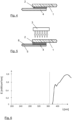
- the spectral irradiance E is plotted in a diagram on the y-axis, for example, in mW/cm 2 /nm, while the wavelength is plotted in nm on the x-axis.
- the UV source 3 emits the UV radiation directly onto the adhesive 2 in the structure shown in Figure 1 . Its peak is at 365 nm.
- the UV-curable adhesive 2 which is free of thermal curing constituents, is thus only activated, but remains liquid in the region in which it was applied.
- an irradiation is also possible at, e.g., a wave length of approximately 430 nm, which means in the range of visible light. Everything said and described thereafter can be used with radiation at such a wavelength analogously.
- the frame 1 is made of transparent material, preferably polyethylene naphthalate (PEN).
- PEN polyethylene naphthalate
- PEN has the property of the UV radiation not passing through the material or only to a very small extent, so that in the case of the renewed irradiation of the structure with the UV source 3 shown in Figure 5 , only a very small amount of UV is introduced into the adhesive 2, which is not the main contributor to curing the adhesive as it is already activated by the procedure illustrated in figure 1 . But the UV radiation is converted into heat in the PEN frame 1 which results in a heating of the adhesive 2 in direct contact thereto.
- PEN polyethylene naphthalate
- the adhesive 2 could also be applied directly on to the full-surface catalyst coated membrane 4 .
- Activating the adhesive 2 by means of UV radiation through the UV source 3 can accordingly take place from above.
- the frame 1 can be positioned over the applied and activated adhesive 3, and without having to flip-over or to move the structure.
- the UV radiation can be made use of to heat the catalytic coating of the membrane 4 through the frame 1. This structure is again simpler in terms of handling.
- FIG. 6 shows, in a diagram analogous to that in Figure 2 , which amounts of energy and which wavelengths penetrate the frame 1 made of PEN. It is noticeable that virtually no UV radiation occurs below 375 nm. The peak of the UV radiation is now at about 385 nm which is, much lower than in the case of the irradiation according to Figure 2 . In the region above 400 nm, part of the light also occurs as visible light in the violet and blue regions. This means that for a wavelength of 365 nm, the PEN causes a wavelength shift, whereby a small proportion of UV radiation and visible light penetrates through the frame 1 made of PEN, while most of the UV energy is converted to heat which heats up the transparent adhesive 2.
- the very thin adhesive 2 which is not yet cured at this time, since the curing via the UV irradiation in Figure 1 has been activated but not yet completed, can thus very easily penetrate through the heat-induced thinning into the pores of the catalytic layer on the membrane 4. It thus essentially penetrates the porous catalytic layer and joins directly with the ionomer of the catalyst coated membrane 4, so that a very deep and stable connection occurs, although the catalytic coating 5, 8 has not been removed in the region of the bonding.
- LOCTITE EA 3060 LC is an adhesive.
- This is an UV-curable cationic epoxy. It has a water content specification of 300 +/- 150 PPM.
- the actual data the inventors collected over >200 units confirm that range with water contents of 200 - 450 PPM with an average of 369 PPM.
- the temperature is controlled to 21+/-1.5°C. They expect that the humidity of the room affects the water content of the adhesive slightly when it is exposed to it for a while.
- the viscosity specification of the LOCTITE EA 3060 LC is 10-14 Pas at room temperature which was comfirmed by measurements of the applicant. The inventors find that it reaches a viscosity of less than 100 mPas at 75°C. They expect that in the temperatures used in the bonding process, which are at about 150 +/- 20°C the viscosity might be less than 10mPas and close to the viscosity of water (1 mPas).
- the catalytic coatings 5, 8 forms microporous surfaces or layers on the ionomer 6. Again, this is followed by a layer of the adhesive 2.
- a tear test with a bonding according to the prior art has now yielded the image shown in Figure 7 , namely that the bonding takes place in such a way that the adhesive 2 is superficially bonded to the surface catalytic coating with limited adhesive penetration, here the catalytic coating 8 of the anode side, and thus cohesively break within the catalyst layer when torn. This corresponds to the problem according to the prior art.
- an alternative method can also be used, preferably with visible light.
- the adhesive 2 can be applied to the frame 1 and/or the membrane 4.
- the previous described step of activating the adhesive 2 with a first exposure to the electromagnetic radiation is obvious. Instead the activation and the heating is carried out with the same exposure to the electromagnetic radiation, preferably blue visible light with a wavelength of about 430 nm.
- the inventors have found out that light at about this wavelength enables the activation and thereby the time delayed curing of the adhesive, i.e. a cationic epoxy with a small content of water, as well as the heating before the adhesive is finally cured.
- Such a single exposure or shot with the light allows a very fast processing of the bonding method.
- a next step can provide that two gas diffusion layers (GDL) 9 are coated with the adhesive 2 in their edge regions, e.g. in turn by means of a deposition method such as screen printing or inkjet printing, as before with the frame 1 or the membrane 4.
- GDL gas diffusion layers
- one of the gas diffusion layers 9 is coated in the edge region in a relatively large portion, the other one in a corresponding smaller portion.
- the two gas diffusion layers are to be, on the left, the gas diffusion layer 9 for the cathode of the fuel cell and on the right, the one for the anode of the fuel cell.
- Each of the gas diffusion layers 9 is provided with a microporous layer MPL 10 on the side which is later made to face towards the membrane 4.
- the adhesive 2 is applied to said MPL 10 of the respective gas diffusion layer 9 and, as is indicated in the illustration of Figure 9 by the arrows and the UV or light source 3, briefly irradiated with electromagnetic radiation to activate the adhesive 2.
- FIG. 11 shows the prepared structure for bonding the two gas diffusion layers 9 to the composite of frame 1 and membrane 4, which composite is already cured.
- the frame 1 with the membrane 4 is introduced in between the two gas diffusion layers 2 with the respective adhesive 2.
- the gas diffusion layer 9 for the anode of the fuel cell which is illustrated in the upper part here, rests within the frame 1 on the membrane 4, and is coated with said adhesive in the edge region.
- the gas diffusion layer 9 of the cathode 9 illustrated below the composite of frame 1 and membrane 4 has a correspondingly wider coating of adhesive, so that it is also bonded to the membrane 4 in the same portion in which the other one of the gas diffusion layers is bonded to the membrane 4, and, at the same time, ensures that the region of the membrane 4 that is already bonded to the frame 1 is bonded to said gas diffusion layer 4 as well.
- the width of the applied adhesive 2 is so large that a bonding between the illustrated gas diffusion layer 9 of the cathode and the frame 1 is also achieved in the edge region.
- the components which are shown so as to form-fit to one another but nevertheless spaced from one another, are now positioned one with respect to the other using a hold-down device 100 or a pressing tool, and are held against each other under slight pressure.
- the hold-down device here comprises a lower part 11 and an upper part 12, which are pressed against each other under slight pressure, in order to position the frame 1 as well as the membrane 4 and the two gas-diffusion layers 9 as the components to be bonded, one against the other in a reliable manner.
- the already activated, UV-curable adhesive is correspondingly heated by means of UV radiation source 3 as an example but not limited to, through two indicated transparent windows 13 in the two parts 11, 12 of the hold-down device 100.
- the transparent window 13 is preferably transparent, e.g. made of glass, quartz or similar. That is, the UV radiation penetrated said transparent window 13 and therefore heats up the respective gas diffusion layer 9 by means of black body effect in the region that has the transparent window 13 formed therein, i.e. in particular in the region where the adhesive 2 was applied as well. Finally, the adhesive 2 is heated, in order for it to become low-viscous, and on the other hand, in order to penetrate through the microporous layer 10 of the respective gas diffusion layer 9 and, on the other hand, the catalytic coating 5, 8 of the membrane 4 in the already-described ways and manners.
- adhesion of the adhesive 2 occurs on the side of the frame 1 on the anode side of the structure, as well as adhesion of the GDL or of the MPL 10 thereof occurs on the frame 1, penetrated by the adhesive 2 laterally next to the membrane 4, so that an overall very dense structure is formed, which is again shown in the illustration of Figure 13 .
- the region indicated with I indicates the connection between the catalyst coated membrane 4 and the frame 1, with the catalytic coating 8 of the anode side of the membrane 4 being penetrated by the adhesive 2.
- the two regions indicated by II show the bonding between the gas diffusion layer 9 or the MPL 10 thereof and the membrane 4.
- the adhesive 2 penetrated into the respective MPL 10 and the respective catalytic coating 5, 8.
- the region indicated by III shows the bonding between the lower one of the gas diffusion layers assigned to the cathode of the fuel cell or of the MPL 10 thereof, and the frame 1.
- the face side of the frame 1 in the region of the other gas diffusion layer 9 is also wetted by an adhesive in the region indicated by IV, so that a sealing of the structure occurs here as well.
- the active region of membrane 4 and gas diffusion layers 9 usable for the active reaction of the substances in the fuel cell then starts in the illustration of Figure 13 , on the right and next to the adhesive 2.
- a cooled region is provided in the upper part 12 and/or the lower part 11 of the hold-down device 100.
- two cooled regions are respectively provided on the right next to the transparent windows 13, both regions indicated by 14.
- other regions in the more or less direct neighborhood of the windows 13 could be cooled as well.
- the cooling in the regions 14 allows for a very targeted heat input and for a very targeted time at which the heat input can be stopped, without allowing for the heat accumulated in the regions of the gas diffusion layers 9 located next to the transparent windows 13 to get back into the region of the adhesive 2.
- a third advantageous effect results in that the temperature decreases in the portions of the gas diffusion layers and of the catalyst coated membrane 4 neighboring the cooled regions 14.
- the adhesive 2 increases in viscosity in these regions, so that the preferably active cooling of the regions 14 also impacts the spatial extent of the adhesive 2 in an advantageous manner or can be limited, respectively.
- this construction allows an ideal bonding of the crucial elements of the membrane electrode arrangement, i.e. in particular the frame 1 and the membrane 4 and the gas diffusion layers 9, which are jointly referred to as the components.
- the adhesive 2 could be cationic epoxy.
- this cationic epoxy contains a small amount of water.
- the diagram in Figure 14 shows the effect of water in the cationic epoxy.
- the horizontal axis is the time.
- the vertical axis shows the epoxide conversion.
- the solid line is a reference to a cationic epoxy completely free of water.
- the dashed and dotted lines showing the curing of the epoxy when having a content of water, i.e. between some 100 ppm and up to 1,5 wt.-%.
- the content of water increases with the changing pattern of the lines as indicated in the explanation box of the diagram.
- Such a small amount of water has the effect, that the curing after the initial activation is delayed in comparison to the cationic epoxy which has no water content.
- This delay in the curing time t is ideal for the methods of the invention as the timely delay can be used for heating and helps to get a good penetration of the micropourous surface with the thinned adhesive 2. Furthermore the faster curing thereafter ensures that the curing is finalized before the thinned adhesive 2 can flow into areas where no adhesive is wanted.
Landscapes
- Chemical & Material Sciences (AREA)
- Life Sciences & Earth Sciences (AREA)
- Engineering & Computer Science (AREA)
- Manufacturing & Machinery (AREA)
- Sustainable Development (AREA)
- Sustainable Energy (AREA)
- Chemical Kinetics & Catalysis (AREA)
- Electrochemistry (AREA)
- General Chemical & Material Sciences (AREA)
- Organic Chemistry (AREA)
- Fuel Cell (AREA)
Description
- The invention relates to a method for bonding components of a fuel cell with a frame and/or with one another, according to the type defined in greater detail in the preamble of
claim 1. The invention further relates to the use of such a method in the manner specified in claims 11 and 12. - The bonding of components of a PEM fuel cell with a frame and/or with one another by means of UV-curable adhesive is known from the prior art. For example,
US 2018/0159160 A1 discloses a frame which is completely permeable to ultraviolet light, in order to be able to have the bonding cured through the frame. Here, the frame is bonded to a membrane having a catalytic coating, with gas diffusion layers also being incorporated in the composite. The structure comes with the disadvantage, that on the one hand, it requires a frame largely transparent to UV radiation, which is not the case with the typically used frames from polyethylene naphthalate (PEN).DE 10 2015 117 077 A1 also describes the bonding of components of a PEM fuel cell within a so-called membrane electrode assembly (MEA). In this case, a UV-curable adhesive is used as well, which here and in the similar documentJP 2016-201183 A1 - A characteristic in a such method lies with the fact that firstly the activation of the UV curable adhesive occurs by means of a small amount of radiation. Curing of the adhesive then starts from this point in time. Activation without having the adhesive cured causes a slow hardening of the adhesive, so that this adhesive continues to harden more and more during the process, and becomes more and more viscous, so that a wetting of all the surfaces to be bonded with the adhesive is difficult as a result.
- The bonding of a catalyst coated membrane (CCM) (Catalyst Coated Membrane) with frames is also of crucial importance for the sealing of fuel cells. Typically, when bonding a full-surface coated membrane, only the surface of the catalyst is bonded to the surface of the frame. Due to a poor adhesion of the catalyst to the actual membrane or its ionomer, leaks, which ensure a mixing of hydrogen and oxygen and thus a defective fuel cell, are now very common, which, with correspondingly high leakage rates, can lead to the failure of the entire fuel cell stack. In practice, it is therefore common and conventional to coat the material of the membranes with catalyst only in the region in which it is also necessary. The edges of the membranes, which are bonded to the frame, are then free of catalyst. They can therefore bond correspondingly well with the frame, so that there is a close adhesion of the membrane material to the frame, without catalyst lying there between.
- However, this structure has the serious disadvantage that the membranes, which are only partially coated with the catalyst, must be positioned very precisely. In addition, the membrane material in the uncoated region is typically dimensioned relatively large in order to ensure secure bonding. The excess material is then cut off and disposed of, so that there is a disproportionate amount of material used in the production.
- Furthermore the coating of sections of the membrane only is very complex and requires specialized equipment and ink catalysts compatible with direct membrane coating. This is a further disadvantage.
- It would therefore be desirable to use a membrane fully coated with catalyst, so that the entire material, which is unrolled, for example, over a roll, can also be used in the structure of the fuel cell. In addition, the required positioning accuracy in a membrane fully coated with catalyst is much less critical than is the case with only partially coated membranes.
-
US 9,831,504 B2 - However, the inventors of the present invention have not been able to determine appreciably better properties of the bonding compared to the prior art mentioned at the outset in experiments with such methods.
- Reference may also be made to
US 2008/0118802 A1 for further prior art. -
DE 10 2012 014 756 A1 discloses a method and a device for bonding at least two components of a fuel cell by means of adhesive, wherein the adhesive is applied directly to at least one predetermined area of at least one component by means of a screen printing process and then irradiated at least to adjust its viscosity and/or to activate the adhesive. - Further prior art is disclosed in the documents
JP 2007 134234 A US 2016/260989 A1 . - The object of the present invention is now to provide an improved method for bonding components of a PEM fuel cell with a frame and/or amongst one another. This object is achieved by a method having the features in
claim 1. Advantageous embodiments and further developments are specified in the dependent claims. Preferred uses are indicated in claims 11 and 12. Advantageous embodiments likewise result from the sub-claims dependent thereon. - The inventors have discovered in their experiments that an adhesive curable by electromagnetic radiation, such as preferably a light or UV-curable adhesive, which is applied to the components and/or to the frame is ideally suited for such bonding. The decisive knowledge of the inventors now is that the adhesive is reduced in viscosity through heat input after the activation of the adhesive, i.e. the adhesive has a lower viscosity. On the one hand, this allows to counteract the initial stages of curing, and on the other hand, to achieve a good penetration into in particular porous or especially microporous surfaces on the components, due to the very low-viscous characteristics of the adhesive achievable thereby. Here, the adhesive that penetrates the porous surfaces, which, due to its largely reduced viscosity, owing to heat, is absorbed also by the smallest pores, allows complete or at least almost complete penetration of the porous surfaces. Therefore a much higher adhesive strength in the bonding is achieved due to the adhesives contact with the basematerial of the component, i.e. in the case of the membrane with the ionomer.
- The method according to the invention offers two different approaches to achieve this great advantage. In the first case the adhesive is activated by light or preferably UV before the components and the frame and/or the components to one another are brought into contact. Thereafter the heat is applied. In the other case the components and the frame and/or the components to one another are brought into contact. The adhesive is thereafter activated and heated by UV or preferably light in one shot.
- In both cases a cationic epoxy which contains water is used to achieve a very good penetration of the porous or microporous surface or layer of the component, involving the respective advantages in view of quality and useful life of the respective fuel cell, or the membrane electrode assembly thereof.
- Cationic epoxy allows the activation by UV light as well as with blue visible light as the inventors find out. It is therefore ideal for the two cases of the two methods (pre-activation and one shot) according to the invention. The content of water, i.e. between 100 ppm and up to 1,5% weight, but not limited thereon, adhesive causes the adhesive to cure delayed. This delay in curing after the activation with light or UV in comparison to the much faster start of the curing of a water-free cationic epoxy is ideal for the use in the invention. Furthermore the small content of water allows a faster curing after it has started delayed also in comparison to a water-free cationic epoxy. This is also advantageous for the inventive methods as the fast curing after the delayed start thereof reduces the flow of the adhesive into unwanted areas.
- According to one embodiment of the invention the water content is about 100 to 500 ppm, preferably 200 to 450 ppm. Furthermore the used cationic epoxy has a viscosity of less than 100 mPas at 75°C. This typically lowers further with rising heat. At a temperature of about 120 to 170°C which according to a further embodiment of the invention is the preferred temperature rage to bond the components together it might be less than 10 mPas.
- An advantageous further embodiment of the invention is characterized in that the components of the PEM fuel cell having a microporous surface at least on a surface bonded to the other component and/or the frame. Especially those components with such microporous surface layers, such as the catalyst on the CCM or the microporous layer (MPL) on the gas diffusion layer (GDL) benefits from the inventive bonding method which allows a at least almost direct bonding of the base materials under the microporous surface layer without the need of removing the same or omitting its application in the bonding regions.
- In a preferred further development of the inventive method the heat is produced in the components through the application of electromagnetic radiation, preferably in the range of visible light or UV. Such a heating with electromagnetic radiation, especially visible light or UV allows a very direct application of the heat to exactly the region where the heat is needed, such as the microporous surface layer. The heat typically arises at the layer which has the least transparency, which is generally the microporous catalyst coating of the membrane or the MPL of the gas diffusion layer. Typically, these can be equated approximately with the properties of a black body that absorbs all of the light and converts it to heat. The heat input is thus produced through the irradiation from the side of the frame or the rear side of the component, mainly in the region in which the adhesive is to be liquefied to a very low viscosity, so that it can take place via capillary forces through the pores of the very strong heating catalyst, which is due to its low thermal mass also being heated very quickly.
- The heating is achieved by two different methods or a combination thereof. The first one is the production of the heat in the microporous surface layer itself. The microporous surface layer, i.e. the catalyst layer of the CCM or the MPL of the GDL, is typically of a very dark color. It is acting as a kind of black body wherein the heat from the exposure to light or UV is produced. As this is the surface or layer to be penetrated with the adhesive while its viscosity is lowered this is ideal. Furthermore the heating of the adhesiveis confined to the irradiated region. Therefore the danger of adhesive flowing into regions where it is not wanted is reduced. The second one is the production of heat in and or through the frame. Typically the frame is transparent. But even though it is transparent, e.g. made of PEN, it will transmit little or even no UV radiation in the wavelength of, for example 365 nm. However, there will be a corresponding heat input due to the radiation being transferred into heat partly in the PEN frame and partly by causing a shift in the wavelength. The radiation shifted in the wavelength can then pass the PEN frame and causes the black body effect in the microporous surface layer. This means that the first and the second method applies here in the kind of a mixture between those. For the use of radiation in the range of visible light, e.g. at 430 nm, the PEN frame is transparent. Therefore the first method applies alone.
- The previously activated adhesive can penetrate the pores of the microporous surface layer before it finally cures. The structure also has the advantage that the heat is introduced in a very targeted manner and almost exclusively in the region of the catalyst or of the gas diffusion layer and the adhesive. A penetration of neighboring components with the adhesive, in particular of the electrochemically active regions in the later structure of the PEM fuel cell of the catalyst coated membrane and/or of the gas diffusion layer respectively arranged adjacent thereto, can be prevented as a result.
- The use of electromagnetic radiation, preferably in the range of visible light or UV, to heat up the adhesive has a further advantage. The use of light or UV allows a high ramp rate of the heat. The heating in the region where it is needed can be achieved in typically less than 5 seconds. This allows the penetration of the microporous surface layer and a very fast and effective bonding process. The method according to this embodiment is therefore ideal for an effective industrial production.
- According to an advantageous further development of the invention, the adhesive is free of thermally crosslinking constituents and thus differs significantly from the approach in the above-mentioned prior art. Unlike in this prior art, it is not the intention of the inventors to hold the adhesive in place. Rather, the activated (once via UV radiation, for example, a short pulse of UV radiation) but still liquid adhesive between the catalyst coated membrane or other components and the frame is applied and heated. Unlike in the prior art, no immediate crosslinking is initiated through the heating of the adhesive. Rather, the adhesive becomes much thinner through the heating, so that its viscosity is thus reduced. The adhesive is already essentially at the place where it should be at this time. The adhesive will flow and pass through the microporous catalyst surface or layer on the membrane or the MPL of a gas diffusion layer through capillary forces, whereby further flow in plane is limited by fast curing. The catalyst layer is porous only to very low viscosity liquids, so that a very thin adhesive having very low viscosity can pass the pores by means of the capillary forces. As a result, trials with investigations of the cross-sectional area under the electron microscope and corresponding trials to pull the bonded layers apart have achieved a much higher bond strength.
- The inventors assume that the adhesive, which has become very thin due to the heating, penetrates the entire layer of the catalyst in its thickness in the region in which the adhesive is applied, so that, in spite of the existing catalytic coating, ultimately, there is bonding between the material of the frame on the one hand and the ionomer, that is, the actual membrane material of the catalyst coated membrane on the other hand. Corresponding sectional images, which have been investigated by electron microscopy, prove this. The same applies to a gas diffusion layer. This layer is also, due to its porosity, deeply penetrated into the material by the adhesive that has become very low-viscous, so that this bonding achieves an ideal adhesion, e.g. also to the frame or on the catalyst-coated membrane, the coating material of which has likewise been penetrated.
- An advantageous development of the method according to the invention further provides that the components and/or the frame are held one on to the other or pressed against one another by means of a hold-down device, with the application by electromagnetic radiation occurring through at least one window in the hold-down device, transparent to the radiation. Such a hold-down device or also a pressing tool with suitably, not too high pressing forces can thus be used in order to position the components and/or the frame with respect to each other. Windows transparent to the radiation can now be provided on the respective points, so that the radiation can advance through the windows, e.g. as far as to the components, in particular to the gas diffusion layers, and thus the required heat can be input, before the adhesive activated by the radiation finally hardens.
- As had already been stated, the heat input can occur via the radiation, which ultimately ensures heating of the component itself or of the catalyst coating of the component, in a very punctual and targeted manner. Nevertheless, it can be provided in a very advantageous embodiment of the method that at least one region of the hold-down device adjacent to the transparent window of the hold-down device is cooled, in particular actively cooled. In this way, the heat input can be restricted to the section corresponding to the transparent window in a very targeted manner, so that the membrane and/or the gas diffusion layers as well as the frame as the components to be bonded are not unnecessarily thermally stressed beyond the gluing spot. The cooling, respectively active cooling, which might be implemented passively, for example via cooling fins, or actively by means of a cooling fluid, is e.g. moved alongside cooling fins or through cooling conduits within these regions, further contributes to heat being dissipated in the edge regions and does not return into the region of the bonding. This way, ultimately the cycle time for forming the bonds can be reduced, achieving economic advantages.
- In the case of bonding a frame to a component, such as a catalyst coated membrane, according to an improved embodiment of the invention the application of electromagnetic radiation at least for heating is carried out from the side of the frame through the same. This allows very easy handling and enables the method in an ideal way to be used in an industrial production line without the need of a complex turnover of the not jet bonded materials or a second source of radiation.
- In the scenario of the invention described as the one shot method a further development provides in the case of bringing the frame and/or the components into contact and heating the adhesive by electromagnetic radiation, the activation and the heating is done by the electromagnetic radiation in the same single exposure of the adhesive to the electromagnetic radiation. This can be done preferably with visible blue light in the range of 430 nm but is not restricted thereon.
- As already indicated, a very advantageous use of the method according to the invention provides for bonding a membrane that is full-surface coated, with a frame. The completely catalyst coated membrane as one of the components can be bonded to the frame securely and reliably by using the method according to the invention, as would otherwise only be possible with a membrane that is exempt of the catalyst coating in the region of the bonding, which, however, would result in the above-described disadvantages.
- An alternative, but equally suitable use of the method according to the invention is to implement said method in order to bond at least one gas diffusion layer as a component with a catalyst coated membrane as the further component and/or the frame. A gas-diffusion layer, with an MEA typically comprising two of such gas diffusion layers, one on the anode side and one on the cathode side, is microporous at least on the side that faces the membrane, in order to distribute the arriving gases as uniformly as possible to the available area of the membrane. The described method is therefore particularly suitable for bonding such a gas diffusion layer, which is in particular directly bonded to the respective side of the membrane and, as required, to the frame.
- A particularly favorable combination of this use provides that at least one, but preferably two gas-diffusion layers are bonded to a previously bonded and cured composite of the catalyst full-surface coated membrane, and the frame. This particularly favorable use of the method according to the invention provides that in a first method step, a catalyst coated membrane (CCM) is accordingly bonded to a frame enclosing said membrane. To that end, the adhesive can preferably be applied to the edge region of the catalyst coated membrane and be correspondingly activated. Then, the frame is placed-on, and the irradiation is continued through the frame. Depending on the wavelength used, the radiation either heats up the PEN film and consequently heats the adhesive and/or directly heats the catalyst layer and consequently the adhesive with the above described effect of the adhesive becoming very low-viscous and completely penetrating the catalytic coating, so that a removal of the catalytic coating of the membrane can be eliminated around the edge regions. This composite of the catalyst full-surface coated membrane and the frame is subsequently correspondingly cured and held available as so-called semi-finished products. This composite is bonded using one, preferably two gas diffusion layers. One diffusion layer, for example that of the anode side, is positioned on the catalyst coated membrane within the frame, and is provided with an adhesive in the edge region, which adhesive comes to rest between the gas diffusion layer and the membrane, while the other gas diffusion layer overlaps the entire membrane and preferably protrudes minimally beyond said membrane. In the edge region, it is likewise coated with the adhesive. In this case, the adhesive is again activated by means of radiation. The components are then joined accordingly and held in position one with respect to the other, using a hold-down device or a pressing device, and is irradiated with radiation preferably through transparent windows of said hold-down device, in order to accordingly heat-up the adhesive and to achieve an ideal bonding of the composite with the two gas diffusion layers, so that as a whole, an intrinsically dense and stably-bonded structure results for the membrane electrode assembly.
- Further advantageous embodiments arise from the exemplary embodiment, which is described in more detail below with reference to the figures.
- Shown are:
- Fig. 1
- a first step of a first method according to the invention;
- Fig. 2
- a plot of the energy of UV radiation of a UV source over the wavelength;
- Fig. 3
- a second step of the a first method according to the invention;
- Fig. 4
- a third step of the first method according to the invention;
- Fig. 5
- a fourth step of the first method according to the invention;
- Fig. 6
- a diagram of the energy of the frame-penetrating radiation of the radiation source according to
Fig. 2 ; - Fig. 7
- a schematic representation of an electron micrograph of a cross-section through a structure having a bonding according to the prior art;
- Fig. 8
- a schematic representation of an electron micrograph of a cross-section through a structure having a bonding according to the invention;
- Fig. 9
- a step from a second method according to the invention;
- Fig. 10
- a schematic representation of an application with UV radiation and activation of the adhesive on two gas diffusion layers;
- Fig. 11
- a schematic illustration of the components provided with the activated adhesive, prior to bonding;
- Fig. 12
- an illustration similar to that of
Figure 11 , with an additional hold-down device for positioning the components during bonding; - Fig. 13
- a schematic illustration of the bonded structure of gas diffusion layers, catalyst coated membrane and frame; and
- Fig. 14
- a schematic diagram illustrating the effect of the water content of a cationic epoxy on curing.
- The invention uses a full-surface membrane coated with catalyst for producing a composite of frame and catalyst coated membrane (CCM) for a PEM fuel cell, in which there are no sections provided for bonding, in which the membrane has not been coated with the catalyst or the catalyst catalytic coating has been removed. The catalyst coated membrane is bonded to the frame in order to produce the composite. In addition, this composite is subsequently bonded to two gas diffusion layers, in order to then form the core of the membrane electrode assembly (MEA). However, the method can also be used for other bonding tasks, or only part of the described bonds.
- A part of this frame is shown and designated 1 in the illustration of
Figure 1 . An adhesive 2 activatable by UV radiation is attached on theframe 1, for example applied via screen printing or inkjet printing in a designated region. The applied adhesive 2 is then briefly irradiated with UV radiation via aUV source 3 in order to activate it. The adhesive 2 remains liquid in this case, the length and/or introduced energy activation via theUV source 3 must therefore be adjusted accordingly. In the illustration ofFigure 2 , the spectral irradiance E is plotted in a diagram on the y-axis, for example, in mW/cm2/nm, while the wavelength is plotted in nm on the x-axis. Under normal conditions, theUV source 3 emits the UV radiation directly onto the adhesive 2 in the structure shown inFigure 1 . Its peak is at 365 nm. As already mentioned, the UV-curable adhesive 2, which is free of thermal curing constituents, is thus only activated, but remains liquid in the region in which it was applied. Instead of the UV radiation, e.g. at the mentioned wavelength and with the parameters mentioned above, an irradiation is also possible at, e.g., a wave length of approximately 430 nm, which means in the range of visible light. Everything said and described thereafter can be used with radiation at such a wavelength analogously. - In the illustration of
Figure 3 , it can be seen how now the catalyst coatedmembrane 4 is placed in exact position on theframe 1 and the adhesive 2. In the illustration ofFigure 4 , it can be seen then that the previous structure of theframe 1, the adhesive 2 and the catalyst coatedmembrane 4 is reversed. Theframe 1 is made of transparent material, preferably polyethylene naphthalate (PEN). PEN has the property of the UV radiation not passing through the material or only to a very small extent, so that in the case of the renewed irradiation of the structure with theUV source 3 shown inFigure 5 , only a very small amount of UV is introduced into the adhesive 2, which is not the main contributor to curing the adhesive as it is already activated by the procedure illustrated infigure 1 . But the UV radiation is converted into heat in thePEN frame 1 which results in a heating of the adhesive 2 in direct contact thereto. - The course that has been described could, of course, also be achieved differently from that described and illustrated here. For example, the adhesive 2 could also be applied directly on to the full-surface catalyst coated
membrane 4 . Activating the adhesive 2 by means of UV radiation through theUV source 3 can accordingly take place from above. Subsequently, theframe 1 can be positioned over the applied and activated adhesive 3, and without having to flip-over or to move the structure. Now, via thesame UV source 3, the UV radiation can be made use of to heat the catalytic coating of themembrane 4 through theframe 1. This structure is again simpler in terms of handling. - The illustration of
Figure 6 shows, in a diagram analogous to that inFigure 2 , which amounts of energy and which wavelengths penetrate theframe 1 made of PEN. It is noticeable that virtually no UV radiation occurs below 375 nm. The peak of the UV radiation is now at about 385 nm which is, much lower than in the case of the irradiation according toFigure 2 . In the region above 400 nm, part of the light also occurs as visible light in the violet and blue regions. This means that for a wavelength of 365 nm, the PEN causes a wavelength shift, whereby a small proportion of UV radiation and visible light penetrates through theframe 1 made of PEN, while most of the UV energy is converted to heat which heats up thetransparent adhesive 2. For a wavelength of 430 nm, most of the UV radiation passes throughframe 1 and likewise through largelytransparent adhesive 2 to the catalytic coating of themembrane 4. There it meets the catalytic coating, which is relatively dark and ultimately acts in the nature of a black body. It therefore absorbs the light energy and converts it largely into heat. Due to the relatively low thermal mass, there is a comparatively strong heating of the adhesive. The adhesive thins, thus obtaining a very low viscosity, since its viscosity decreases with increasing heat. The verythin adhesive 2, which is not yet cured at this time, since the curing via the UV irradiation inFigure 1 has been activated but not yet completed, can thus very easily penetrate through the heat-induced thinning into the pores of the catalytic layer on themembrane 4. It thus essentially penetrates the porous catalytic layer and joins directly with the ionomer of the catalyst coatedmembrane 4, so that a very deep and stable connection occurs, although thecatalytic coating - In a successful series of experiments the inventors used LOCTITE EA 3060 LC as an adhesive. This is an UV-curable cationic epoxy. It has a water content specification of 300 +/- 150 PPM. The actual data the inventors collected over >200 units confirm that range with water contents of 200 - 450 PPM with an average of 369 PPM. In the cleanroom where they run the trials they have a relative humidity of 42 +/- 2%. The temperature is controlled to 21+/-1.5°C. They expect that the humidity of the room affects the water content of the adhesive slightly when it is exposed to it for a while.
- The viscosity specification of the LOCTITE EA 3060 LC is 10-14 Pas at room temperature which was comfirmed by measurements of the applicant. The inventors find that it reaches a viscosity of less than 100 mPas at 75°C. They expect that in the temperatures used in the bonding process, which are at about 150 +/- 20°C the viscosity might be less than 10mPas and close to the viscosity of water (1 mPas).
- Experiments by the inventors in cross-sections which have been studied by electron microscopy confirm this. In the illustration of
Figure 7 , such an image is indicated purely by way of example. A section having a thickness of about 30 µm shows, from bottom to top in the right region of the adhesive 2, the catalytic coating on the cathode side, which is designated here by 5. Then follows the ionomer (denoted by 6) of themembrane 4 and a reinforcing ply, denoted by 7, enclosed with a second layer ofionomer 6. On theother ionomer layer 6, the catalytic coating with the anode catalyst is shown (and denoted by 8) with thecatalytic coating 5, therefore, being the cathode catalyst. Thecatalytic coatings ionomer 6. Again, this is followed by a layer of the adhesive 2. A tear test with a bonding according to the prior art has now yielded the image shown inFigure 7 , namely that the bonding takes place in such a way that the adhesive 2 is superficially bonded to the surface catalytic coating with limited adhesive penetration, here thecatalytic coating 8 of the anode side, and thus cohesively break within the catalyst layer when torn. This corresponds to the problem according to the prior art. - In the illustration of
Figure 8 , the same image is shown again with the type of bonding described here. InFigure 8 , on the left, the construction is again shown, in which it has been recognized by inspection via the electron microscopic evaluation that the catalyst has changed somewhat in this region and obviously is completely penetrated by the adhesive 2. This illustration has been omitted here due to the limited display options in the line drawing. However, what is decisive is the result of a tear test shown in the right region ofFigure 8 . It will be recognized that, unlike the prior art, theionomer 6 ruptures along the reinforcingply 7 and remains firmly bonded to thecatalytic coating 8 of the anode side and the adhesive 2. The strength of the bonding surface is therefore obviously higher than the strength of theactual membrane 4, so that a structure to be realized particularly solid and tight could be achieved by the method according to the invention. - An alternative method can also be used, preferably with visible light. As illustrated in
figure 9 which in fact shows almost the same asfigure 5 the adhesive 2 can be applied to theframe 1 and/or themembrane 4. The previous described step of activating the adhesive 2 with a first exposure to the electromagnetic radiation is obvious. Instead the activation and the heating is carried out with the same exposure to the electromagnetic radiation, preferably blue visible light with a wavelength of about 430 nm. The inventors have found out that light at about this wavelength enables the activation and thereby the time delayed curing of the adhesive, i.e. a cationic epoxy with a small content of water, as well as the heating before the adhesive is finally cured. Such a single exposure or shot with the light allows a very fast processing of the bonding method. - This composite described in the previous Figures of
frame 1 and themembrane 4 can now be held available as some kind of semi-finished product. A next step can provide that two gas diffusion layers (GDL) 9 are coated with the adhesive 2 in their edge regions, e.g. in turn by means of a deposition method such as screen printing or inkjet printing, as before with theframe 1 or themembrane 4. This is explained in greater detail in the illustration ofFigure 10 using the example of two gas diffusion layers 9. As an example design and process but not limited to, one of the gas diffusion layers 9 is coated in the edge region in a relatively large portion, the other one in a corresponding smaller portion. In this case, the two gas diffusion layers are to be, on the left, thegas diffusion layer 9 for the cathode of the fuel cell and on the right, the one for the anode of the fuel cell. Each of the gas diffusion layers 9 is provided with amicroporous layer MPL 10 on the side which is later made to face towards themembrane 4. The adhesive 2 is applied to saidMPL 10 of the respectivegas diffusion layer 9 and, as is indicated in the illustration ofFigure 9 by the arrows and the UV orlight source 3, briefly irradiated with electromagnetic radiation to activate the adhesive 2. - The illustration of
Figure 11 shows the prepared structure for bonding the twogas diffusion layers 9 to the composite offrame 1 andmembrane 4, which composite is already cured. Theframe 1 with themembrane 4 is introduced in between the twogas diffusion layers 2 with therespective adhesive 2. Thegas diffusion layer 9 for the anode of the fuel cell, which is illustrated in the upper part here, rests within theframe 1 on themembrane 4, and is coated with said adhesive in the edge region. Thegas diffusion layer 9 of thecathode 9 illustrated below the composite offrame 1 andmembrane 4 has a correspondingly wider coating of adhesive, so that it is also bonded to themembrane 4 in the same portion in which the other one of the gas diffusion layers is bonded to themembrane 4, and, at the same time, ensures that the region of themembrane 4 that is already bonded to theframe 1 is bonded to saidgas diffusion layer 4 as well. In addition, the width of the applied adhesive 2 is so large that a bonding between the illustratedgas diffusion layer 9 of the cathode and theframe 1 is also achieved in the edge region. The components, which are shown so as to form-fit to one another but nevertheless spaced from one another, are now positioned one with respect to the other using a hold-down device 100 or a pressing tool, and are held against each other under slight pressure. This is accordingly indicated in the illustration ofFigure 12 . The hold-down device here comprises a lower part 11 and an upper part 12, which are pressed against each other under slight pressure, in order to position theframe 1 as well as themembrane 4 and the two gas-diffusion layers 9 as the components to be bonded, one against the other in a reliable manner. The already activated, UV-curable adhesive is correspondingly heated by means ofUV radiation source 3 as an example but not limited to, through two indicatedtransparent windows 13 in the two parts 11, 12 of the hold-down device 100. In this case, thetransparent window 13 is preferably transparent, e.g. made of glass, quartz or similar. That is, the UV radiation penetrated saidtransparent window 13 and therefore heats up the respectivegas diffusion layer 9 by means of black body effect in the region that has thetransparent window 13 formed therein, i.e. in particular in the region where the adhesive 2 was applied as well. Finally, the adhesive 2 is heated, in order for it to become low-viscous, and on the other hand, in order to penetrate through themicroporous layer 10 of the respectivegas diffusion layer 9 and, on the other hand, thecatalytic coating membrane 4 in the already-described ways and manners. - At the same time, adhesion of the adhesive 2 occurs on the side of the
frame 1 on the anode side of the structure, as well as adhesion of the GDL or of theMPL 10 thereof occurs on theframe 1, penetrated by the adhesive 2 laterally next to themembrane 4, so that an overall very dense structure is formed, which is again shown in the illustration ofFigure 13 . Here, the region indicated with I indicates the connection between the catalyst coatedmembrane 4 and theframe 1, with thecatalytic coating 8 of the anode side of themembrane 4 being penetrated by the adhesive 2. The two regions indicated by II show the bonding between thegas diffusion layer 9 or theMPL 10 thereof and themembrane 4. Here, the adhesive 2 penetrated into therespective MPL 10 and the respectivecatalytic coating MPL 10 thereof, and theframe 1. The face side of theframe 1 in the region of the othergas diffusion layer 9 is also wetted by an adhesive in the region indicated by IV, so that a sealing of the structure occurs here as well. The active region ofmembrane 4 andgas diffusion layers 9 usable for the active reaction of the substances in the fuel cell then starts in the illustration ofFigure 13 , on the right and next to the adhesive 2. - In order to, on the one hand, protect this electrochemically-active region, and to maintain the heat input for liquefying the adhesive 2 within the desired range in a targeted manner, it can be provided that a cooled region is provided in the upper part 12 and/or the lower part 11 of the hold-down device 100. In the illustration of
Figure 12 , two cooled regions are respectively provided on the right next to thetransparent windows 13, both regions indicated by 14. Furthermore other regions in the more or less direct neighborhood of thewindows 13 could be cooled as well. These cooledregions 14 ensure that the heat only builds up in the region of the adhesive 2 in a targeted manner, or is induced into said region respectively, and that the later electrochemically active region cannot be impaired due to this heat input. In addition, the cooling in theregions 14 allows for a very targeted heat input and for a very targeted time at which the heat input can be stopped, without allowing for the heat accumulated in the regions of thegas diffusion layers 9 located next to thetransparent windows 13 to get back into the region of the adhesive 2. A third advantageous effect results in that the temperature decreases in the portions of the gas diffusion layers and of the catalyst coatedmembrane 4 neighboring the cooledregions 14. In other words, the adhesive 2 increases in viscosity in these regions, so that the preferably active cooling of theregions 14 also impacts the spatial extent of the adhesive 2 in an advantageous manner or can be limited, respectively. - All in all, this construction allows an ideal bonding of the crucial elements of the membrane electrode arrangement, i.e. in particular the
frame 1 and themembrane 4 and the gas diffusion layers 9, which are jointly referred to as the components. - As already mentioned above the adhesive 2 could be cationic epoxy. Preferably this cationic epoxy contains a small amount of water. The diagram in
Figure 14 shows the effect of water in the cationic epoxy. The horizontal axis is the time. The vertical axis shows the epoxide conversion. The solid line is a reference to a cationic epoxy completely free of water. The dashed and dotted lines showing the curing of the epoxy when having a content of water, i.e. between some 100 ppm and up to 1,5 wt.-%. The content of water increases with the changing pattern of the lines as indicated in the explanation box of the diagram. Such a small amount of water has the effect, that the curing after the initial activation is delayed in comparison to the cationic epoxy which has no water content. After such a timely delay the curing of the cationic epoxy with water will then be even faster than of the cationic epoxy which has no water content. Therefor a very small amount of water is enough. This might be introduced into the epoxy by using it in a surrounding with high air humidity. - This delay in the curing time t is ideal for the methods of the invention as the timely delay can be used for heating and helps to get a good penetration of the micropourous surface with the thinned
adhesive 2. Furthermore the faster curing thereafter ensures that the curing is finalized before the thinned adhesive 2 can flow into areas where no adhesive is wanted.
Claims (14)
- A method for bonding components (4, 9) of a PEM fuel cell with a frame (1) and/or amongst one another, wherefore an adhesive (2) curable by electromagnetic radiation in the range of visible light or UV is applied to the frame (1) and/or the at least one component (4, 9), wherein the adhesive (2) is activated by the electromagnetic radiation and heated after the frame (1) and/or the components (4, 9) are brought into contact; orthe frame (1) and/or the components (4, 9) are brought into contact and the adhesive (2) is exposed to electromagnetic radiation for activating and heating; wherein the heat reduces the viscosity of the adhesive (2) before it is finally cured; characterized in thatthe adhesive (2) is a cationic epoxy which contains water.
- The method according to claim 1,
characterized in that
the cationic epoxy having a water content of 100 to 500 ppm, preferably 200 to 450 ppm. - The method according to claim 1 or 2,
characterized in that
the cationic epoxy having a viscosity of less than 100 mPas at 75°C. - The method according to claim 1, 2 or 3
characterized in that
the heating is done up to temperatures of 100 to 200°C, preferably up to 120 to 170°C. - The method according to one of claims 1 to 4,
characterized in that
the components (4, 9) of the PEM fuel cell having a microporous surface layer (5,8,10) at least on a surface bonded to the other component (4,9) and/or the frame. - The method according to one of claims 1 to 5,
characterized in that
the heat is produced in the components (4,9) through application of electromagnetic radiation, preferably in the range of visible light or UV. - The method according to anyone of claims 1 to 6,
characterized in that
the adhesive (2) is free of thermally crosslinking constituents. - The method according to anyone of claims 1 to 7,
characterized in that
the components (4, 9) and/or the frame (1) are held one on to the other by means of a hold-down device, wherein the irradiation with electromagnetic radiation occurs through at least one window (13) in the hold-down device, transparent to the radiation. - The method according to claim 8,
characterized in that
at least one region adjacent to the transparent window (13) in the hold-down device is cooled, in particular actively cooled. - The method according to anyone of claims 1 to 9,
characterized in that
in the case of bonding a frame (1) to a component (4,9), such as a catalyst coated membrane (4), the application of electromagnetic radiation at least for heating is carried out from the side of the frame (1) through the same. - The method according to anyone of claims 1 to 10,
characterized in that
in the case of bringing the frame (1) and/or the components (4, 9) into contact and heating the adhesive (2) by electromagnetic radiation, the activation and the heating is done by the electromagnetic radiation in the same single exposure of the adhesive to the electromagnetic radiation. - Use of the method according to one of claims 1 to 11
for bonding a full-surface catalyst coated membrane (4) as one of the components, to the frame (1). - Use of the method according to one of claims 1 to 11
for bonding at least one gas-diffusion layer (9) as the component with a catalyst coated membrane (4) as a further component and/or with the frame (1). - The use according to claim 12 or 13,
characterized in that
at least one, preferably two gas-diffusion layers (9) are bonded to a previously bonded and cured composite of the full-surface catalyst coated membrane (4) and the frame (1).
Applications Claiming Priority (2)
| Application Number | Priority Date | Filing Date | Title |
|---|---|---|---|
| DE102019006820.3A DE102019006820A1 (en) | 2019-09-30 | 2019-09-30 | Method for bonding components of a fuel cell |
| PCT/EP2020/065804 WO2021063550A1 (en) | 2019-09-30 | 2020-06-08 | A method for bonding components of a fuel cell |
Publications (4)
| Publication Number | Publication Date |
|---|---|
| EP4038676A1 EP4038676A1 (en) | 2022-08-10 |
| EP4038676B1 true EP4038676B1 (en) | 2023-09-27 |
| EP4038676C0 EP4038676C0 (en) | 2023-09-27 |
| EP4038676B8 EP4038676B8 (en) | 2024-03-06 |
Family
ID=68733031
Family Applications (2)
| Application Number | Title | Priority Date | Filing Date |
|---|---|---|---|
| EP19812944.7A Pending EP4038675A1 (en) | 2019-09-30 | 2019-11-26 | A method for bonding components of a fuel cell |
| EP20731457.6A Active EP4038676B8 (en) | 2019-09-30 | 2020-06-08 | A method for bonding components of a fuel cell |
Family Applications Before (1)
| Application Number | Title | Priority Date | Filing Date |
|---|---|---|---|
| EP19812944.7A Pending EP4038675A1 (en) | 2019-09-30 | 2019-11-26 | A method for bonding components of a fuel cell |
Country Status (7)
| Country | Link |
|---|---|
| US (2) | US12438163B2 (en) |
| EP (2) | EP4038675A1 (en) |
| JP (2) | JP7373058B2 (en) |
| KR (2) | KR102818028B1 (en) |
| CN (2) | CN114503315A (en) |
| DE (1) | DE102019006820A1 (en) |
| WO (2) | WO2021063525A1 (en) |
Families Citing this family (3)
| Publication number | Priority date | Publication date | Assignee | Title |
|---|---|---|---|---|
| DE102019006820A1 (en) | 2019-09-30 | 2021-04-01 | Daimler Ag | Method for bonding components of a fuel cell |
| US20240282983A1 (en) * | 2021-05-19 | 2024-08-22 | Threebond Co., Ltd. | Gasket molding method, fuel cell, fuel cell production method, sealing method, and gasket molding device |
| CN116111130B (en) * | 2022-12-30 | 2025-09-30 | 重庆创新燃料电池技术产业研究院有限公司 | A wet-wet layered gluing composite sealing method for air-cooled proton exchange membrane fuel cells |
Family Cites Families (23)
| Publication number | Priority date | Publication date | Assignee | Title |
|---|---|---|---|---|
| FR1379264A (en) * | 1963-12-24 | 1964-11-20 | Thomson Houston Comp Francaise | Method of assembling elements of an electric motor |
| US4507340A (en) | 1980-07-31 | 1985-03-26 | Raychem Corporation | Adhesives and devices coated therewith |
| JP2002363506A (en) * | 2001-05-29 | 2002-12-18 | Three M Innovative Properties Co | UV activated adhesive film |
| US6955739B2 (en) * | 2001-06-19 | 2005-10-18 | 3M Innovative Properties Company | Method for adhering substrates using ultraviolet activatable adhesive film and an ultraviolet irradiation apparatus |
| JP4498664B2 (en) | 2002-05-15 | 2010-07-07 | 大日本印刷株式会社 | Separator member for flat-type polymer electrolyte fuel cell and polymer electrolyte fuel cell using the separator member |
| JP2007134234A (en) | 2005-11-11 | 2007-05-31 | Nissan Motor Co Ltd | Sealing material coating method and separator for fuel cell separator |
| JP5068052B2 (en) * | 2006-09-29 | 2012-11-07 | 昭和電工株式会社 | FUEL CELL SEPARATOR, FUEL CELL CELL, FUEL CELL CELL UNIT, AND METHOD FOR PRODUCING FUEL CELL SEPARATOR AND FUEL CELL CELL UNIT |
| US20080118802A1 (en) | 2006-11-16 | 2008-05-22 | Peter Szrama | Fully Catalyzed Membrane Assembly With Attached Border |
| US8268510B2 (en) | 2008-12-22 | 2012-09-18 | GM Global Technology Operations LLC | Fuel cell fabrication using photopolymer based processes |
| WO2013069491A1 (en) | 2011-11-10 | 2013-05-16 | 本田技研工業株式会社 | Fuel cell assembly and method of manufacturing same, and bonding part manufacturing method and device |
| DE102012014756A1 (en) * | 2012-07-26 | 2014-01-30 | Daimler Ag | Method and device for connecting at least two components of a fuel cell |
| JPWO2014017524A1 (en) | 2012-07-26 | 2016-07-11 | デンカ株式会社 | Resin composition |
| DE102012014757A1 (en) | 2012-07-26 | 2014-01-30 | Daimler Ag | Method and device for connecting components of a fuel cell |
| KR101245356B1 (en) | 2012-08-30 | 2013-03-19 | (주)정원기술 | Pressure head for flip chip bonder |
| JP6222143B2 (en) | 2014-03-18 | 2017-11-01 | トヨタ自動車株式会社 | Fuel cell and fuel cell manufacturing method |
| JP6079741B2 (en) | 2014-10-08 | 2017-02-15 | トヨタ自動車株式会社 | Method for producing a single fuel cell |
| JP6237675B2 (en) | 2015-03-03 | 2017-11-29 | トヨタ自動車株式会社 | FUEL CELL SINGLE CELL AND METHOD FOR PRODUCING FUEL CELL SINGLE CELL |
| JP6485178B2 (en) | 2015-04-07 | 2019-03-20 | トヨタ自動車株式会社 | Method for producing a single fuel cell |
| EP3386284B1 (en) * | 2015-11-30 | 2021-05-05 | Hitachi Automotive Systems, Ltd. | Electronic control device and method for manufacturing electronic control device |
| JP6547729B2 (en) | 2016-12-01 | 2019-07-24 | トヨタ自動車株式会社 | Fuel cell manufacturing method |
| US10569298B2 (en) * | 2017-09-27 | 2020-02-25 | Intel Corporation | Substrate with epoxy cured by ultraviolet laser |
| JP6863264B2 (en) | 2017-12-19 | 2021-04-21 | トヨタ自動車株式会社 | Fuel cell manufacturing method |
| DE102019006820A1 (en) | 2019-09-30 | 2021-04-01 | Daimler Ag | Method for bonding components of a fuel cell |
-
2019
- 2019-09-30 DE DE102019006820.3A patent/DE102019006820A1/en active Pending
- 2019-11-26 JP JP2022516595A patent/JP7373058B2/en active Active
- 2019-11-26 EP EP19812944.7A patent/EP4038675A1/en active Pending
- 2019-11-26 US US17/764,662 patent/US12438163B2/en active Active
- 2019-11-26 CN CN201980100904.2A patent/CN114503315A/en active Pending
- 2019-11-26 KR KR1020227009794A patent/KR102818028B1/en active Active
- 2019-11-26 WO PCT/EP2019/082500 patent/WO2021063525A1/en not_active Ceased
-
2020
- 2020-06-08 EP EP20731457.6A patent/EP4038676B8/en active Active
- 2020-06-08 WO PCT/EP2020/065804 patent/WO2021063550A1/en not_active Ceased
- 2020-06-08 KR KR1020227009795A patent/KR102803372B1/en active Active
- 2020-06-08 US US17/764,674 patent/US20220328850A1/en active Pending
- 2020-06-08 JP JP2022516596A patent/JP7320670B2/en active Active
- 2020-06-08 CN CN202080067797.0A patent/CN114450828B/en active Active
Also Published As
| Publication number | Publication date |
|---|---|
| CN114450828A (en) | 2022-05-06 |
| CN114450828B (en) | 2024-11-01 |
| WO2021063550A1 (en) | 2021-04-08 |
| KR20220052979A (en) | 2022-04-28 |
| DE102019006820A1 (en) | 2021-04-01 |
| EP4038675A1 (en) | 2022-08-10 |
| KR102803372B1 (en) | 2025-05-02 |
| EP4038676A1 (en) | 2022-08-10 |
| US20220328850A1 (en) | 2022-10-13 |
| JP2022548361A (en) | 2022-11-18 |
| EP4038676C0 (en) | 2023-09-27 |
| KR102818028B1 (en) | 2025-06-10 |
| JP2022548360A (en) | 2022-11-18 |
| JP7320670B2 (en) | 2023-08-03 |
| EP4038676B8 (en) | 2024-03-06 |
| WO2021063525A1 (en) | 2021-04-08 |
| US20220344679A1 (en) | 2022-10-27 |
| CN114503315A (en) | 2022-05-13 |
| KR20220054628A (en) | 2022-05-03 |
| JP7373058B2 (en) | 2023-11-01 |
| US12438163B2 (en) | 2025-10-07 |
Similar Documents
| Publication | Publication Date | Title |
|---|---|---|
| EP4038676B1 (en) | A method for bonding components of a fuel cell | |
| CA2908287C (en) | Method of manufacturing unit fuel cell | |
| CN106133971A (en) | Fuel cell, fuel cell manufacturing method | |
| JP5695086B2 (en) | 5-layer membrane electrode assembly having peripheral portions bonded thereto and manufacturing method thereof | |
| US20160260993A1 (en) | Single fuel cell and method of manufacturing single fuel cell | |
| JP4882541B2 (en) | Manufacturing method of electrolyte membrane for fuel cell and membrane electrode assembly | |
| JP2005005012A (en) | Method for applying adhesive to fuel cell separator | |
| JP2005249937A (en) | Color filter manufacturing method and apparatus | |
| US10964958B2 (en) | Method for manufacturing integrated sheet | |
| US20200251752A1 (en) | Method for manufacturing separator for fuel cell | |
| JP2016162652A (en) | Method for manufacturing fuel battery single cell | |
| JP2019096389A (en) | Method of manufacturing fuel battery cell | |
| EP4039659A1 (en) | Heat-reflecting member, and method for manufacturing glass member having heat-reflecting layer included therein | |
| JP2008269909A (en) | Method for manufacturing membrane electrode assembly used in fuel cell, and membrane electrode assembly | |
| CN115917806B (en) | Method for producing a laminate of at least two sub-layers of a membrane electrode unit | |
| CN115832353B (en) | A sealing structure for a fuel cell membrane electrode. | |
| JP2020064814A (en) | Manufacturing method of fuel battery cell | |
| KR20240092926A (en) | Manufacturing method of fuel cell | |
| JP2022150046A (en) | Manufacturing method of fuel cell |
Legal Events
| Date | Code | Title | Description |
|---|---|---|---|
| STAA | Information on the status of an ep patent application or granted ep patent |
Free format text: STATUS: UNKNOWN |
|
| STAA | Information on the status of an ep patent application or granted ep patent |
Free format text: STATUS: THE INTERNATIONAL PUBLICATION HAS BEEN MADE |
|
| PUAI | Public reference made under article 153(3) epc to a published international application that has entered the european phase |
Free format text: ORIGINAL CODE: 0009012 |
|
| STAA | Information on the status of an ep patent application or granted ep patent |
Free format text: STATUS: REQUEST FOR EXAMINATION WAS MADE |
|
| 17P | Request for examination filed |
Effective date: 20220303 |
|
| AK | Designated contracting states |
Kind code of ref document: A1 Designated state(s): AL AT BE BG CH CY CZ DE DK EE ES FI FR GB GR HR HU IE IS IT LI LT LU LV MC MK MT NL NO PL PT RO RS SE SI SK SM TR |
|
| DAV | Request for validation of the european patent (deleted) | ||
| DAX | Request for extension of the european patent (deleted) | ||
| GRAP | Despatch of communication of intention to grant a patent |
Free format text: ORIGINAL CODE: EPIDOSNIGR1 |
|
| STAA | Information on the status of an ep patent application or granted ep patent |
Free format text: STATUS: GRANT OF PATENT IS INTENDED |
|
| RIC1 | Information provided on ipc code assigned before grant |
Ipc: H01M 8/10 20160101ALN20230424BHEP Ipc: H01M 8/1018 20160101ALI20230424BHEP Ipc: H01M 8/1004 20160101ALI20230424BHEP Ipc: H01M 8/0286 20160101ALI20230424BHEP Ipc: H01M 8/0284 20160101ALI20230424BHEP Ipc: H01M 8/0273 20160101AFI20230424BHEP |
|
| INTG | Intention to grant announced |
Effective date: 20230515 |
|
| GRAS | Grant fee paid |
Free format text: ORIGINAL CODE: EPIDOSNIGR3 |
|
| GRAA | (expected) grant |
Free format text: ORIGINAL CODE: 0009210 |
|
| STAA | Information on the status of an ep patent application or granted ep patent |
Free format text: STATUS: THE PATENT HAS BEEN GRANTED |
|
| AK | Designated contracting states |
Kind code of ref document: B1 Designated state(s): AL AT BE BG CH CY CZ DE DK EE ES FI FR GB GR HR HU IE IS IT LI LT LU LV MC MK MT NL NO PL PT RO RS SE SI SK SM TR |
|
| REG | Reference to a national code |
Ref country code: GB Ref legal event code: FG4D |
|
| REG | Reference to a national code |
Ref country code: CH Ref legal event code: EP |
|
| RIN2 | Information on inventor provided after grant (corrected) |
Inventor name: PATTERSON, COLE Inventor name: MAASSEN, THOMAS Inventor name: SZPERKOWICZ, MICHAEL Inventor name: MEDINA, MICHAEL |
|
| REG | Reference to a national code |
Ref country code: DE Ref legal event code: R096 Ref document number: 602020018298 Country of ref document: DE |
|
| REG | Reference to a national code |
Ref country code: IE Ref legal event code: FG4D |
|
| U01 | Request for unitary effect filed |
Effective date: 20230927 |
|
| U07 | Unitary effect registered |
Designated state(s): AT BE BG DE DK EE FI FR IT LT LU LV MT NL PT SE SI Effective date: 20231005 |
|
| PG25 | Lapsed in a contracting state [announced via postgrant information from national office to epo] |
Ref country code: GR Free format text: LAPSE BECAUSE OF FAILURE TO SUBMIT A TRANSLATION OF THE DESCRIPTION OR TO PAY THE FEE WITHIN THE PRESCRIBED TIME-LIMIT Effective date: 20231228 |
|
| PG25 | Lapsed in a contracting state [announced via postgrant information from national office to epo] |
Ref country code: RS Free format text: LAPSE BECAUSE OF FAILURE TO SUBMIT A TRANSLATION OF THE DESCRIPTION OR TO PAY THE FEE WITHIN THE PRESCRIBED TIME-LIMIT Effective date: 20230927 Ref country code: NO Free format text: LAPSE BECAUSE OF FAILURE TO SUBMIT A TRANSLATION OF THE DESCRIPTION OR TO PAY THE FEE WITHIN THE PRESCRIBED TIME-LIMIT Effective date: 20231227 Ref country code: HR Free format text: LAPSE BECAUSE OF FAILURE TO SUBMIT A TRANSLATION OF THE DESCRIPTION OR TO PAY THE FEE WITHIN THE PRESCRIBED TIME-LIMIT Effective date: 20230927 Ref country code: GR Free format text: LAPSE BECAUSE OF FAILURE TO SUBMIT A TRANSLATION OF THE DESCRIPTION OR TO PAY THE FEE WITHIN THE PRESCRIBED TIME-LIMIT Effective date: 20231228 |
|
| REG | Reference to a national code |
Ref country code: CH Ref legal event code: PK Free format text: BERICHTIGUNG B8 |
|
| PG25 | Lapsed in a contracting state [announced via postgrant information from national office to epo] |
Ref country code: IS Free format text: LAPSE BECAUSE OF FAILURE TO SUBMIT A TRANSLATION OF THE DESCRIPTION OR TO PAY THE FEE WITHIN THE PRESCRIBED TIME-LIMIT Effective date: 20240127 |
|
| PG25 | Lapsed in a contracting state [announced via postgrant information from national office to epo] |
Ref country code: ES Free format text: LAPSE BECAUSE OF FAILURE TO SUBMIT A TRANSLATION OF THE DESCRIPTION OR TO PAY THE FEE WITHIN THE PRESCRIBED TIME-LIMIT Effective date: 20230927 |
|
| PG25 | Lapsed in a contracting state [announced via postgrant information from national office to epo] |
Ref country code: SM Free format text: LAPSE BECAUSE OF FAILURE TO SUBMIT A TRANSLATION OF THE DESCRIPTION OR TO PAY THE FEE WITHIN THE PRESCRIBED TIME-LIMIT Effective date: 20230927 Ref country code: RO Free format text: LAPSE BECAUSE OF FAILURE TO SUBMIT A TRANSLATION OF THE DESCRIPTION OR TO PAY THE FEE WITHIN THE PRESCRIBED TIME-LIMIT Effective date: 20230927 Ref country code: IS Free format text: LAPSE BECAUSE OF FAILURE TO SUBMIT A TRANSLATION OF THE DESCRIPTION OR TO PAY THE FEE WITHIN THE PRESCRIBED TIME-LIMIT Effective date: 20240127 Ref country code: ES Free format text: LAPSE BECAUSE OF FAILURE TO SUBMIT A TRANSLATION OF THE DESCRIPTION OR TO PAY THE FEE WITHIN THE PRESCRIBED TIME-LIMIT Effective date: 20230927 Ref country code: CZ Free format text: LAPSE BECAUSE OF FAILURE TO SUBMIT A TRANSLATION OF THE DESCRIPTION OR TO PAY THE FEE WITHIN THE PRESCRIBED TIME-LIMIT Effective date: 20230927 Ref country code: SK Free format text: LAPSE BECAUSE OF FAILURE TO SUBMIT A TRANSLATION OF THE DESCRIPTION OR TO PAY THE FEE WITHIN THE PRESCRIBED TIME-LIMIT Effective date: 20230927 |
|
| PG25 | Lapsed in a contracting state [announced via postgrant information from national office to epo] |
Ref country code: PL Free format text: LAPSE BECAUSE OF FAILURE TO SUBMIT A TRANSLATION OF THE DESCRIPTION OR TO PAY THE FEE WITHIN THE PRESCRIBED TIME-LIMIT Effective date: 20230927 |
|
| REG | Reference to a national code |
Ref country code: DE Ref legal event code: R097 Ref document number: 602020018298 Country of ref document: DE |
|
| U20 | Renewal fee for the european patent with unitary effect paid |
Year of fee payment: 5 Effective date: 20240613 |
|
| PLBE | No opposition filed within time limit |
Free format text: ORIGINAL CODE: 0009261 |
|
| STAA | Information on the status of an ep patent application or granted ep patent |
Free format text: STATUS: NO OPPOSITION FILED WITHIN TIME LIMIT |
|
| 26N | No opposition filed |
Effective date: 20240628 |
|
| PG25 | Lapsed in a contracting state [announced via postgrant information from national office to epo] |
Ref country code: MC Free format text: LAPSE BECAUSE OF FAILURE TO SUBMIT A TRANSLATION OF THE DESCRIPTION OR TO PAY THE FEE WITHIN THE PRESCRIBED TIME-LIMIT Effective date: 20230927 |
|
| REG | Reference to a national code |
Ref country code: CH Ref legal event code: PL |
|
| U1N | Appointed representative for the unitary patent procedure changed after the registration of the unitary effect |
Representative=s name: PLATZOEDER PATENTANWALTSGESELLSCHAFT MBH; DE |
|
| PG25 | Lapsed in a contracting state [announced via postgrant information from national office to epo] |
Ref country code: IE Free format text: LAPSE BECAUSE OF NON-PAYMENT OF DUE FEES Effective date: 20240608 |
|
| PG25 | Lapsed in a contracting state [announced via postgrant information from national office to epo] |
Ref country code: CH Free format text: LAPSE BECAUSE OF NON-PAYMENT OF DUE FEES Effective date: 20240630 |
|
| PGFP | Annual fee paid to national office [announced via postgrant information from national office to epo] |
Ref country code: GB Payment date: 20250620 Year of fee payment: 6 |
|
| U20 | Renewal fee for the european patent with unitary effect paid |
Year of fee payment: 6 Effective date: 20250623 |
|
| PG25 | Lapsed in a contracting state [announced via postgrant information from national office to epo] |
Ref country code: CY Free format text: LAPSE BECAUSE OF FAILURE TO SUBMIT A TRANSLATION OF THE DESCRIPTION OR TO PAY THE FEE WITHIN THE PRESCRIBED TIME-LIMIT; INVALID AB INITIO Effective date: 20200608 |
|
| PG25 | Lapsed in a contracting state [announced via postgrant information from national office to epo] |
Ref country code: HU Free format text: LAPSE BECAUSE OF FAILURE TO SUBMIT A TRANSLATION OF THE DESCRIPTION OR TO PAY THE FEE WITHIN THE PRESCRIBED TIME-LIMIT; INVALID AB INITIO Effective date: 20200608 |