EP4038594B1 - Electronic tag - Google Patents
Electronic tag Download PDFInfo
- Publication number
- EP4038594B1 EP4038594B1 EP20790039.0A EP20790039A EP4038594B1 EP 4038594 B1 EP4038594 B1 EP 4038594B1 EP 20790039 A EP20790039 A EP 20790039A EP 4038594 B1 EP4038594 B1 EP 4038594B1
- Authority
- EP
- European Patent Office
- Prior art keywords
- electronic tag
- proximity
- threshold
- response
- receive
- Prior art date
- Legal status (The legal status is an assumption and is not a legal conclusion. Google has not performed a legal analysis and makes no representation as to the accuracy of the status listed.)
- Active
Links
Images

Classifications
-
- G—PHYSICS
- G08—SIGNALLING
- G08B—SIGNALLING SYSTEMS, e.g. PERSONAL CALLING SYSTEMS; ORDER TELEGRAPHS; ALARM SYSTEMS
- G08B21/00—Alarms responsive to a single specified undesired or abnormal condition and not otherwise provided for
- G08B21/18—Status alarms
- G08B21/22—Status alarms responsive to presence or absence of persons
-
- G—PHYSICS
- G01—MEASURING; TESTING
- G01S—RADIO DIRECTION-FINDING; RADIO NAVIGATION; DETERMINING DISTANCE OR VELOCITY BY USE OF RADIO WAVES; LOCATING OR PRESENCE-DETECTING BY USE OF THE REFLECTION OR RERADIATION OF RADIO WAVES; ANALOGOUS ARRANGEMENTS USING OTHER WAVES
- G01S19/00—Satellite radio beacon positioning systems; Determining position, velocity or attitude using signals transmitted by such systems
- G01S19/01—Satellite radio beacon positioning systems transmitting time-stamped messages, e.g. GPS [Global Positioning System], GLONASS [Global Orbiting Navigation Satellite System] or GALILEO
- G01S19/13—Receivers
- G01S19/21—Interference related issues ; Issues related to cross-correlation, spoofing or other methods of denial of service
-
- G—PHYSICS
- G08—SIGNALLING
- G08B—SIGNALLING SYSTEMS, e.g. PERSONAL CALLING SYSTEMS; ORDER TELEGRAPHS; ALARM SYSTEMS
- G08B21/00—Alarms responsive to a single specified undesired or abnormal condition and not otherwise provided for
- G08B21/02—Alarms for ensuring the safety of persons
- G08B21/0202—Child monitoring systems using a transmitter-receiver system carried by the parent and the child
-
- G—PHYSICS
- G08—SIGNALLING
- G08B—SIGNALLING SYSTEMS, e.g. PERSONAL CALLING SYSTEMS; ORDER TELEGRAPHS; ALARM SYSTEMS
- G08B21/00—Alarms responsive to a single specified undesired or abnormal condition and not otherwise provided for
- G08B21/02—Alarms for ensuring the safety of persons
- G08B21/0202—Child monitoring systems using a transmitter-receiver system carried by the parent and the child
- G08B21/0236—Threshold setting
-
- G—PHYSICS
- G08—SIGNALLING
- G08B—SIGNALLING SYSTEMS, e.g. PERSONAL CALLING SYSTEMS; ORDER TELEGRAPHS; ALARM SYSTEMS
- G08B21/00—Alarms responsive to a single specified undesired or abnormal condition and not otherwise provided for
- G08B21/02—Alarms for ensuring the safety of persons
- G08B21/0202—Child monitoring systems using a transmitter-receiver system carried by the parent and the child
- G08B21/0241—Data exchange details, e.g. data protocol
- G08B21/0247—System arrangements wherein the alarm criteria uses signal strength
-
- G—PHYSICS
- G08—SIGNALLING
- G08B—SIGNALLING SYSTEMS, e.g. PERSONAL CALLING SYSTEMS; ORDER TELEGRAPHS; ALARM SYSTEMS
- G08B21/00—Alarms responsive to a single specified undesired or abnormal condition and not otherwise provided for
- G08B21/02—Alarms for ensuring the safety of persons
- G08B21/0202—Child monitoring systems using a transmitter-receiver system carried by the parent and the child
- G08B21/0241—Data exchange details, e.g. data protocol
- G08B21/025—System arrangements wherein the alarm criteria uses absence of reply signal after an elapsed time
-
- G—PHYSICS
- G08—SIGNALLING
- G08B—SIGNALLING SYSTEMS, e.g. PERSONAL CALLING SYSTEMS; ORDER TELEGRAPHS; ALARM SYSTEMS
- G08B21/00—Alarms responsive to a single specified undesired or abnormal condition and not otherwise provided for
- G08B21/02—Alarms for ensuring the safety of persons
- G08B21/0202—Child monitoring systems using a transmitter-receiver system carried by the parent and the child
- G08B21/0269—System arrangements wherein the object is to detect the exact location of child or item using a navigation satellite system, e.g. GPS
-
- G—PHYSICS
- G08—SIGNALLING
- G08B—SIGNALLING SYSTEMS, e.g. PERSONAL CALLING SYSTEMS; ORDER TELEGRAPHS; ALARM SYSTEMS
- G08B21/00—Alarms responsive to a single specified undesired or abnormal condition and not otherwise provided for
- G08B21/02—Alarms for ensuring the safety of persons
- G08B21/0202—Child monitoring systems using a transmitter-receiver system carried by the parent and the child
- G08B21/0286—Tampering or removal detection of the child unit from child or article
-
- G—PHYSICS
- G08—SIGNALLING
- G08B—SIGNALLING SYSTEMS, e.g. PERSONAL CALLING SYSTEMS; ORDER TELEGRAPHS; ALARM SYSTEMS
- G08B21/00—Alarms responsive to a single specified undesired or abnormal condition and not otherwise provided for
- G08B21/02—Alarms for ensuring the safety of persons
- G08B21/0202—Child monitoring systems using a transmitter-receiver system carried by the parent and the child
- G08B21/0288—Attachment of child unit to child/article
-
- G—PHYSICS
- G08—SIGNALLING
- G08B—SIGNALLING SYSTEMS, e.g. PERSONAL CALLING SYSTEMS; ORDER TELEGRAPHS; ALARM SYSTEMS
- G08B21/00—Alarms responsive to a single specified undesired or abnormal condition and not otherwise provided for
- G08B21/18—Status alarms
- G08B21/182—Level alarms, e.g. alarms responsive to variables exceeding a threshold
-
- G—PHYSICS
- G08—SIGNALLING
- G08B—SIGNALLING SYSTEMS, e.g. PERSONAL CALLING SYSTEMS; ORDER TELEGRAPHS; ALARM SYSTEMS
- G08B29/00—Checking or monitoring of signalling or alarm systems; Prevention or correction of operating errors, e.g. preventing unauthorised operation
- G08B29/02—Monitoring continuously signalling or alarm systems
-
- H—ELECTRICITY
- H04—ELECTRIC COMMUNICATION TECHNIQUE
- H04W—WIRELESS COMMUNICATION NETWORKS
- H04W4/00—Services specially adapted for wireless communication networks; Facilities therefor
- H04W4/02—Services making use of location information
- H04W4/021—Services related to particular areas, e.g. point of interest [POI] services, venue services or geofences
-
- H—ELECTRICITY
- H04—ELECTRIC COMMUNICATION TECHNIQUE
- H04W—WIRELESS COMMUNICATION NETWORKS
- H04W4/00—Services specially adapted for wireless communication networks; Facilities therefor
- H04W4/02—Services making use of location information
- H04W4/023—Services making use of location information using mutual or relative location information between multiple location based services [LBS] targets or of distance thresholds
-
- H—ELECTRICITY
- H04—ELECTRIC COMMUNICATION TECHNIQUE
- H04W—WIRELESS COMMUNICATION NETWORKS
- H04W4/00—Services specially adapted for wireless communication networks; Facilities therefor
- H04W4/02—Services making use of location information
- H04W4/029—Location-based management or tracking services
Definitions
- the present invention relates to an electronic tag, such as an electronic tag for monitoring the location of a person.
- An offender may be fitted with an electronic tag in order to enforce conditions prescribed to the offender as a punishment for an offence, as a condition of their release on bail or as a condition of their early release from prison.
- conditions prescribed to the offender are curfews (which prevent the offender leaving their home at certain times, especially at night) and exclusion zones (which prevent the offender from visiting certain places, such as a victim's home).
- Electronic tags can also be used to monitor the location of vulnerable patients, such as the elderly or people with mental health disorders.
- Electronic tags typically send and receive radiofrequency communications with other devices. For example, the electronic tag may determine its location by exchanging radiofrequency signals between the electronic tag and a fixed monitoring unit, or by receiving GPS signals from GPS satellites. Also, the electronic tag may send radiofrequency communications, for example, to raise an alarm when a prescribed condition is breached.
- the person wearing the electronic tag would like to disguise their location, for example, to allow them to break their curfew or visit a location in one of their exclusion zones. Removing the electronic tag is usually not an option as electronic tags tend to be securely attached to the person and have tamper detection, making it impossible to remove the electronic tag without detection. So, the person wearing the tag may instead try to prevent the electronic tag from making and receiving radiofrequency communications in an attempt to disguise their real location or in an attempt to prevent the electronic tag from reporting or raising an alarm.
- EP 2,290,391 A1 attempts to determine if the radiofrequency communications are being deliberately blocked by measuring reflections caused by the metal foil.
- this technique cannot distinguish metal foil from other objects surrounding the electronic tag, including the body of the person wearing the electronic tag. This tends to lead to false positives which need to be investigated, wasting resources.
- EP 2,290,391 A1 and US 8,723,669 B2 both disclose tracking devices that are able to determine if radio-frequency communications to or from the tracking device are being deliberately blocked by an object, such as metal foil, placed in proximity to the device.
- an electronic tag configured to be secured to a body of a person.
- the electronic tag comprises an antenna configured to transmit or receive an electromagnetic signal and an inductive proximity sensor.
- the inductive proximity sensor is configured to determine a proximity of a metallic object to the electronic tag, based on electromagnetic coupling between the inductive proximity sensor and the metallic object.
- the inductive proximity sensor is also configured to determine, based on the proximity being below a proximity threshold, that a metallic object is attenuating the electromagnetic signal transmitted or received by the antenna.
- the inductive proximity sensor includes an inductor (such as a coil) configured to generate a first alternating magnetic field which has no effect on a non-metallic object but which is coupled into nearby metallic objects (such as metal foil wrapped around the electronic tag) inducing eddy currents.
- the inductive proximity sensor can more accurately identify deliberate blocking (such as that caused by metal foil wrapped around the electronic tag), the inductive proximity sensor is much less prone to false positives.
- a metallic object is attenuating the electromagnetic signal transmitted or received by the antenna in response to both the proximity being below the proximity threshold and based on a signal strength of the electromagnetic signal.
- the signal strength may indicate that the electronic tag is unable to receive an electromagnetic signal.
- the signal strength may have reduced while the proximity has been below the proximity threshold and optionally the signal strength may vary with the value of the proximity.
- the electronic tag may more reliably distinguish metallic objects that happen to be in the vicinity of the person (such as furniture, radiators, etc) from deliberate attempts to block transmission or reception of electromagnetic signals caused by, for example, wrapping metal foil around the electronic tag. This is because metallic objects in the vicinity of the person may be detected as having a proximity below the proximity threshold but will tend not to block or significantly attenuate the reception of electromagnetic signals. In contrast, deliberate attempts to block transmission or reception of electromagnetic signals, for example, by wrapping metal foil around the electronic tag, will cause detection of a proximity below the proximity threshold and block (or at least attenuate) the reception of electromagnetic signals.
- the electronic tag being unable to receive an electromagnetic signal may mean that the antenna received an electromagnetic signal (such as a location signal from a GPS satellite) below a detection threshold or noise floor.
- the inductive proximity sensor may be activated in response to the electronic tag being unable to receive an electromagnetic signal for a period of time.
- the inductive proximity sensor may be activated in response to the electronic tag being unable to receive a reply to a transmitted electromagnetic signal within a period of time.
- the inductive proximity sensor may check for obstructions only if the electronic tag is unable to communicate with the outside world, that is, if the electronic tag does not receive an electromagnetic signal for a period of time, or does not receive a reply to a transmitted electromagnetic signal within a period of time, as the lack of communications may indicate that an attempt is being made to deliberately block electromagnetic signals to/from the electronic tag.
- the proximity sensor may be activated if no external location signal has been received for a particular period of time which might indicate that the electronic tag has been wrapped in metal foil.
- the electronic tag may be configured to determine the location of the electronic tag based on an external location signal.
- the inductive proximity sensor may be activated in response to the electronic tag being unable to receive the external location signal for a period of time.
- the external location signal may be a GPS signal (for example, from a GPS satellite).
- the electronic tag may determine the location of the electronic tag based on the GPS signal.
- the inductive proximity sensor determines periodically the proximity of the metallic object to the electronic tag. It may be desirable to check periodically for metallic objects in proximity of the electronic tag, regardless of whether or not the electronic tag is able to transmit/receive electromagnetic signals (for example, even if the electronic tag is able to receive an external location signal) because an attempt may have been made to block the electromagnetic signals with a metallic object which does not completely block receipt of electromagnetic signals.
- the electronic tag further comprises a computer-readable storage medium (such as a memory) configured to store a blocked state.
- the blocked state indicates that the electronic tag is blocked based on a plurality of proximity determinations being below the proximity threshold.
- the blocked state indicates that the electronic tag is unblocked based on a plurality of proximity determinations being above the proximity threshold.
- the blocked state is based on a value of a counter.
- the value of the counter is configured to be changed (for example, incremented) towards a blocked threshold in response to a proximity determination of the plurality of proximity determinations being below the proximity threshold.
- the value of the counter is configured to be changed (for example, decremented) towards an unblocked threshold in response to a proximity determination of the plurality of proximity determinations being above the proximity threshold.
- the blocked state is set to blocked in response to the value of the counter reaching the blocked threshold.
- the blocked state is set to unblocked in response to the value of the counter reaching the unblocked threshold.
- the electronic tag By determining the blocked state in this way, using a plurality of proximity determinations recorded, for example, with a counter, the electronic tag is better able to distinguish between deliberate attempts to block the electromagnetic tag from metallic objects which are detected that happen to be in the vicinity of the electronic tag.
- the electronic tag may be configured to generate a message indicating a change in the blocked state.
- the message may be transmitted to a monitoring station in response to the electronic tag being able to transmit and/or receive an electromagnetic signal. It may be determined that the electronic tag is able to transmit and/or receive an electromagnetic signal based on determining that the proximity is above the proximity threshold. While the metallic object, such as the metal foil, is obstructing the antenna, the electronic tag may be prevented from transmitting an alarm signal to the monitoring centre. At these times, a record of the times when the proximity was below the proximity threshold is recorded on the computer-readable storage medium.
- the proximity changes to being above the proximity threshold which indicates to the electronic tag to send the record to the monitoring centre for investigation.
- a metallic object is attenuating the electromagnetic signal in response to the proximity being below a proximity threshold for one or more of: a period of time; a plurality of proximity measurements; and a plurality of failed attempts to obtain an external location signal.
- the metallic object may be metal foil, for example, aluminium foil.
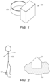
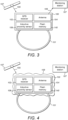
- Figure 1 illustrates an electronic tag 100 with a tether 101 for securing the electronic tag 100 to an offender 103, typically securing the electronic tag 100 around their ankle (as shown in Figure 2 ).
- the electronic tag 100 monitors the position of the offender 103, so it can be determined whether the offender 103 is adhering to one or more prescribed conditions, such as remaining outside an exclusion zone 120 around a victim's house 121 prescribed as a condition of the early release of offender 103 from prison.
- FIG 3 shows how the electronic tag 100 determines the position of the offender 103.
- the electronic tag 100 has a GPS receiver 102 which periodically receives GPS signals 105 from GPS satellites 107.
- the GPS receiver 102 uses the received GPS signals 105 to determine the location of the electronic tag 100, and hence the location of the offender 103.
- the electronic tag 100 sends location information 109 indicating the location of the offender 103 to a monitoring station 107 via antenna 104 as a radiofrequency signal, so that the monitoring station 107 can monitor where the offender 103 is in relation to their exclusion zone 120.
- the offender 103 may attempt to disguise their location (for example, to allow the offender 103 to visit a location inside the exclusion zone 120). As shown in Figure 4 , the offender 103 may do this by wrapping the electronic tag 100 in metal foil 108 (such as aluminium foil) to prevent the electronic tag 100 from receiving the GPS signals 105 and to prevent the electronic tag 100 from sending location information 109 to the monitoring station 107.
- metal foil 108 such as aluminium foil
- Figure 5 illustrates an inductive proximity sensor 106 for detecting whether there is metal in proximity to the electronic tag 100 which might indicate that metal foil 108 has been wrapped around the electronic tag 100 in an attempt to block the receipt of GPS signals 105 and the transmission of location information 109.
- the inductive proximity sensor 106 has a coil 112 connected to a capacitor 113 to form a resonant circuit 115.
- a resonant drive circuit 116 provides an alternating current drive signal to match the frequency of the resonant circuit 115 which generates a first alternating magnetic field 110 which is coupled into any metallic object (such as metal foil 108) in the vicinity, inducing eddy currents 111 in the metallic object.
- These eddy currents 111 generate a second alternating magnetic field 113 which is coupled back into the coil 112, which increases the load on the resonant circuit 115 influencing the amplitude and/or frequency of the resonant circuit 115.
- the changes in amplitude and/or frequency of the resonant circuit 115 can be determined by detector 114 to give an output which is related to the proximity of the metal object.
- a proximity threshold can be determined by determining a first output of the proximity sensor 106 with metal foil 108 wrapped around it and determining a second output without any metal nearby.
- the proximity threshold is, for example, the average of these first and second outputs.
- the metallic object detected by the electronic tag 100 as being in the vicinity of the electronic tag 100 might not be metal foil 108 but could instead be some incidental metallic object that happens to be in the vicinity (such as furniture, a radiator, etc.) that has not been placed there deliberately in an attempt to block the electronic tag 100.
- metal foil 108 is in proximity of the electronic tag 100 when the output of the proximity sensor 106 is below the proximity threshold on a number of occasions when the GPS receiver 102 also fails to receive GPS signals 105 from GPS satellites 107, or when a reduction in the strength of the GPS signals 105 coincides with the output of the proximity sensor 106 falling below the proximity threshold.
- the output of the proximity sensor 106 may be below the proximity threshold for a minimum number of occasions before it can be established that a deliberate attempt is being made to block the electronic tag 100 with metal foil 108.
- the inductive proximity sensor 106 may be activated periodically (for example, on a regular schedule) to check for metal in proximity of the electronic tag 100.
- the inductive proximity sensor 106 may be activated when the strength of the GPS signals 105 is suddenly reduced, or when the GPS receiver 102 has failed to receive any GPS signals 105 for a selected period of time or on a number of occasions when the GPS receiver 102 has polled for GPS signals 105.
- the inductive proximity sensor 106 may be activated when the electronic tag 100 has been unable to receive a reply to a transmitted signal (such as a reply from the monitoring station 107 to confirm that the monitoring station 107 has received location information 109) within a selected period of time or on a number of occasions.
- Memory 140 (such as flash memory or another computer-readable storage medium) stores a counter which is initially set to zero when the electronic tag 100 is manufactured or reset. Each time the inductive proximity sensor 106 is activated, the output of the inductive proximity sensor 106 is compared with the proximity threshold and it is confirmed whether the GPS receiver 102 is able to receive GPS signals 105. If the output from the proximity sensor 106 is below the proximity threshold and the GPS receiver 105 is unable to receive a GPS signal 105, the electronic tag 100 increments the counter. If the output from the proximity sensor 106 is above the proximity threshold and the GPS receiver 105 is able to receive a GPS signal 105, the electronic tag 100 decrements the counter. When the counter reaches an upper (blocked) threshold, this indicates that it is likely that metal foil 108 has been detected wrapped around the electronic tag 100 and a blocked state stored in memory 140 is set to blocked, and a record of the blocking start time is recorded in the memory 140.
- an upper (blocked) threshold this indicates that it is likely that metal foil 108 has been detected
- the electronic tag 100 continues to activate the inductive proximity sensor 106 periodically, to check for changes in the blocked state. Again, each time the inductive proximity sensor 106 is activated, the output of the inductive proximity sensor 106 is compared with the proximity threshold and it is confirmed whether the GPS receiver 102 is able to receive GPS signals 105. If the output from the proximity sensor 106 is below the proximity threshold and the GPS receiver 105 is unable to receive a GPS signal 105, the electronic tag 100 increments the counter but caps the counter at the upper threshold. If the output from the proximity sensor 106 is above the proximity threshold and the GPS receiver 105 is able to receive a GPS signal 105, the electronic tag 100 decrements the counter.
- the electronic tag 100 In response to the blocked state changing to blocked, the electronic tag 100 will generate a message to be sent to the monitoring station 107 via antenna 104 the next time the blocked state changes to unblocked.
- the message may include the blocking start time and the blocking end time.
- the message will alert operators at the monitoring station 107 that the offender 103 was attempting to block the electronic tag 100 using metal foil 108 so that they can investigate and, if necessary, reprimand the person for tampering with their electronic tag 100.
Landscapes
- General Physics & Mathematics (AREA)
- Physics & Mathematics (AREA)
- Emergency Management (AREA)
- Business, Economics & Management (AREA)
- Child & Adolescent Psychology (AREA)
- Health & Medical Sciences (AREA)
- General Health & Medical Sciences (AREA)
- Engineering & Computer Science (AREA)
- Computer Networks & Wireless Communication (AREA)
- Signal Processing (AREA)
- Radar, Positioning & Navigation (AREA)
- Remote Sensing (AREA)
- Computer Security & Cryptography (AREA)
- Burglar Alarm Systems (AREA)
- Surgical Instruments (AREA)
- Apparatuses And Processes For Manufacturing Resistors (AREA)
- Adhesives Or Adhesive Processes (AREA)
Description
- The present invention relates to an electronic tag, such as an electronic tag for monitoring the location of a person.
- An offender may be fitted with an electronic tag in order to enforce conditions prescribed to the offender as a punishment for an offence, as a condition of their release on bail or as a condition of their early release from prison. Examples of conditions that can be enforced by an electronic tag are curfews (which prevent the offender leaving their home at certain times, especially at night) and exclusion zones (which prevent the offender from visiting certain places, such as a victim's home). Electronic tags can also be used to monitor the location of vulnerable patients, such as the elderly or people with mental health disorders.
- Electronic tags typically send and receive radiofrequency communications with other devices. For example, the electronic tag may determine its location by exchanging radiofrequency signals between the electronic tag and a fixed monitoring unit, or by receiving GPS signals from GPS satellites. Also, the electronic tag may send radiofrequency communications, for example, to raise an alarm when a prescribed condition is breached.
- Sometimes, the person wearing the electronic tag would like to disguise their location, for example, to allow them to break their curfew or visit a location in one of their exclusion zones. Removing the electronic tag is usually not an option as electronic tags tend to be securely attached to the person and have tamper detection, making it impossible to remove the electronic tag without detection. So, the person wearing the tag may instead try to prevent the electronic tag from making and receiving radiofrequency communications in an attempt to disguise their real location or in an attempt to prevent the electronic tag from reporting or raising an alarm.
- One way to attempt this is to deliberately block the radiofrequency communications, for example, by wrapping a sheet of metal foil around the electronic tag.
EP 2,290,391 A1 attempts to determine if the radiofrequency communications are being deliberately blocked by measuring reflections caused by the metal foil. However, this technique cannot distinguish metal foil from other objects surrounding the electronic tag, including the body of the person wearing the electronic tag. This tends to lead to false positives which need to be investigated, wasting resources. - It would, therefore, be desirable to find a way to more accurately identify deliberate blocking caused by metal foil being wrapped around an electronic tag.
-
EP 2,290,391 A1 andUS 8,723,669 B2 both disclose tracking devices that are able to determine if radio-frequency communications to or from the tracking device are being deliberately blocked by an object, such as metal foil, placed in proximity to the device. - According to a first aspect of the invention, there is provided an electronic tag configured to be secured to a body of a person. The electronic tag comprises an antenna configured to transmit or receive an electromagnetic signal and an inductive proximity sensor. The inductive proximity sensor is configured to determine a proximity of a metallic object to the electronic tag, based on electromagnetic coupling between the inductive proximity sensor and the metallic object. The inductive proximity sensor is also configured to determine, based on the proximity being below a proximity threshold, that a metallic object is attenuating the electromagnetic signal transmitted or received by the antenna.
- By using an inductive proximity sensor, it is possible to distinguish metallic obstructions (such as metal foil wrapped around the electronic tag) which are likely to represent deliberate attempts to block the electromagnetic signal transmitted or received by the antenna, from everyday non-metallic objects in the vicinity of the electronic tag (such as the body of the person wearing the electronic tag). The inductive proximity sensor includes an inductor (such as a coil) configured to generate a first alternating magnetic field which has no effect on a non-metallic object but which is coupled into nearby metallic objects (such as metal foil wrapped around the electronic tag) inducing eddy currents. These eddy currents generate a second alternating magnetic field in the metallic object which is coupled back into the inductor, leading to a measurable change in the inductance of the inductor which can be related to the proximity of the metallic object. Since the inductive proximity sensor can more accurately identify deliberate blocking (such as that caused by metal foil wrapped around the electronic tag), the inductive proximity sensor is much less prone to false positives.
- It may be determined that a metallic object is attenuating the electromagnetic signal transmitted or received by the antenna in response to both the proximity being below the proximity threshold and based on a signal strength of the electromagnetic signal. For example, the signal strength may indicate that the electronic tag is unable to receive an electromagnetic signal. Alternatively, the signal strength may have reduced while the proximity has been below the proximity threshold and optionally the signal strength may vary with the value of the proximity.
- By using both the proximity being below the proximity threshold and the signal strength of the electronic signal, the electronic tag may more reliably distinguish metallic objects that happen to be in the vicinity of the person (such as furniture, radiators, etc) from deliberate attempts to block transmission or reception of electromagnetic signals caused by, for example, wrapping metal foil around the electronic tag. This is because metallic objects in the vicinity of the person may be detected as having a proximity below the proximity threshold but will tend not to block or significantly attenuate the reception of electromagnetic signals. In contrast, deliberate attempts to block transmission or reception of electromagnetic signals, for example, by wrapping metal foil around the electronic tag, will cause detection of a proximity below the proximity threshold and block (or at least attenuate) the reception of electromagnetic signals. The electronic tag being unable to receive an electromagnetic signal may mean that the antenna received an electromagnetic signal (such as a location signal from a GPS satellite) below a detection threshold or noise floor.
- The inductive proximity sensor may be activated in response to the electronic tag being unable to receive an electromagnetic signal for a period of time. The inductive proximity sensor may be activated in response to the electronic tag being unable to receive a reply to a transmitted electromagnetic signal within a period of time.
- The inductive proximity sensor may check for obstructions only if the electronic tag is unable to communicate with the outside world, that is, if the electronic tag does not receive an electromagnetic signal for a period of time, or does not receive a reply to a transmitted electromagnetic signal within a period of time, as the lack of communications may indicate that an attempt is being made to deliberately block electromagnetic signals to/from the electronic tag. For example, the proximity sensor may be activated if no external location signal has been received for a particular period of time which might indicate that the electronic tag has been wrapped in metal foil. By providing an initial check for whether the electronic tag might be obstructed by an object before activating the inductive proximity sensor to confirm whether that object is metallic, power consumption may be reduced and battery life may be improved.
- The electronic tag may be configured to determine the location of the electronic tag based on an external location signal. The inductive proximity sensor may be activated in response to the electronic tag being unable to receive the external location signal for a period of time. The external location signal may be a GPS signal (for example, from a GPS satellite). The electronic tag may determine the location of the electronic tag based on the GPS signal.
- The inductive proximity sensor determines periodically the proximity of the metallic object to the electronic tag. It may be desirable to check periodically for metallic objects in proximity of the electronic tag, regardless of whether or not the electronic tag is able to transmit/receive electromagnetic signals (for example, even if the electronic tag is able to receive an external location signal) because an attempt may have been made to block the electromagnetic signals with a metallic object which does not completely block receipt of electromagnetic signals.
- The electronic tag further comprises a computer-readable storage medium (such as a memory) configured to store a blocked state. The blocked state indicates that the electronic tag is blocked based on a plurality of proximity determinations being below the proximity threshold. The blocked state indicates that the electronic tag is unblocked based on a plurality of proximity determinations being above the proximity threshold.
- The blocked state is based on a value of a counter. The value of the counter is configured to be changed (for example, incremented) towards a blocked threshold in response to a proximity determination of the plurality of proximity determinations being below the proximity threshold. The value of the counter is configured to be changed (for example, decremented) towards an unblocked threshold in response to a proximity determination of the plurality of proximity determinations being above the proximity threshold.
- The blocked state is set to blocked in response to the value of the counter reaching the blocked threshold. The blocked state is set to unblocked in response to the value of the counter reaching the unblocked threshold.
- By determining the blocked state in this way, using a plurality of proximity determinations recorded, for example, with a counter, the electronic tag is better able to distinguish between deliberate attempts to block the electromagnetic tag from metallic objects which are detected that happen to be in the vicinity of the electronic tag.
- The electronic tag may be configured to generate a message indicating a change in the blocked state. The message may be transmitted to a monitoring station in response to the electronic tag being able to transmit and/or receive an electromagnetic signal. It may be determined that the electronic tag is able to transmit and/or receive an electromagnetic signal based on determining that the proximity is above the proximity threshold. While the metallic object, such as the metal foil, is obstructing the antenna, the electronic tag may be prevented from transmitting an alarm signal to the monitoring centre. At these times, a record of the times when the proximity was below the proximity threshold is recorded on the computer-readable storage medium. As soon as the metallic object obstructing the antenna is removed, for example, as soon as the person wearing the electronic tag removes the metal foil they had wrapped around it, the proximity changes to being above the proximity threshold which indicates to the electronic tag to send the record to the monitoring centre for investigation.
- It may be determined that a metallic object is attenuating the electromagnetic signal in response to the proximity being below a proximity threshold for one or more of: a period of time; a plurality of proximity measurements; and a plurality of failed attempts to obtain an external location signal.
- The metallic object may be metal foil, for example, aluminium foil.
- The invention shall now be described, by way of example only, with reference to the accompanying drawings in which:
-
Figure 1 shows an electronic tag with a tether for attaching the electronic tag to a person; -
Figure 2 shows the electronic tag secured around the ankle of a person using the tether; -
Figure 3 shows an electronic tag which determines the position of the person based on GPS signals received by the electronic tag; -
Figure 4 shows an electronic tag where receipt of the GPS signals is blocked by metal foil wrapped around the electronic tag; and -
Figure 5 shows an inductive proximity sensor for detecting whether metal foil has been wrapped around the electronic tag. -
Figure 1 illustrates anelectronic tag 100 with atether 101 for securing theelectronic tag 100 to anoffender 103, typically securing theelectronic tag 100 around their ankle (as shown inFigure 2 ). Theelectronic tag 100 monitors the position of theoffender 103, so it can be determined whether theoffender 103 is adhering to one or more prescribed conditions, such as remaining outside anexclusion zone 120 around a victim'shouse 121 prescribed as a condition of the early release ofoffender 103 from prison. -
Figure 3 shows how theelectronic tag 100 determines the position of theoffender 103. Theelectronic tag 100 has aGPS receiver 102 which periodically receives GPS signals 105 fromGPS satellites 107. TheGPS receiver 102 uses the receivedGPS signals 105 to determine the location of theelectronic tag 100, and hence the location of theoffender 103. Theelectronic tag 100 sendslocation information 109 indicating the location of theoffender 103 to amonitoring station 107 viaantenna 104 as a radiofrequency signal, so that themonitoring station 107 can monitor where theoffender 103 is in relation to theirexclusion zone 120. - The
offender 103 may attempt to disguise their location (for example, to allow theoffender 103 to visit a location inside the exclusion zone 120). As shown inFigure 4 , theoffender 103 may do this by wrapping theelectronic tag 100 in metal foil 108 (such as aluminium foil) to prevent theelectronic tag 100 from receiving the GPS signals 105 and to prevent theelectronic tag 100 from sendinglocation information 109 to themonitoring station 107. -
Figure 5 illustrates aninductive proximity sensor 106 for detecting whether there is metal in proximity to theelectronic tag 100 which might indicate thatmetal foil 108 has been wrapped around theelectronic tag 100 in an attempt to block the receipt ofGPS signals 105 and the transmission oflocation information 109. - The
inductive proximity sensor 106 has acoil 112 connected to acapacitor 113 to form aresonant circuit 115. Aresonant drive circuit 116 provides an alternating current drive signal to match the frequency of theresonant circuit 115 which generates a first alternatingmagnetic field 110 which is coupled into any metallic object (such as metal foil 108) in the vicinity, inducingeddy currents 111 in the metallic object. Theseeddy currents 111 generate a second alternatingmagnetic field 113 which is coupled back into thecoil 112, which increases the load on theresonant circuit 115 influencing the amplitude and/or frequency of theresonant circuit 115. The closer the metal object is, the greater the inducededdy currents 111 and the more effect the secondmagnetic field 113 has on the magnitude and frequency of oscillation of theresonant circuit 115. The changes in amplitude and/or frequency of theresonant circuit 115 can be determined bydetector 114 to give an output which is related to the proximity of the metal object. - A proximity threshold can be determined by determining a first output of the
proximity sensor 106 withmetal foil 108 wrapped around it and determining a second output without any metal nearby. The proximity threshold is, for example, the average of these first and second outputs. When it is determined that the output of theproximity sensor 106 is below the proximity threshold, it can be confirmed that a metallic object is in the vicinity of theelectronic tag 100, which could bemetal foil 108 which the offender has wrapped aroundelectronic tag 100 in an attempt to block theelectronic tag 100 from receiving theGPS signal 105 or transmitting thelocation information 109. - However, it is possible that the metallic object detected by the
electronic tag 100 as being in the vicinity of theelectronic tag 100 might not bemetal foil 108 but could instead be some incidental metallic object that happens to be in the vicinity (such as furniture, a radiator, etc.) that has not been placed there deliberately in an attempt to block theelectronic tag 100. To distinguish between deliberate attempts to block theelectronic tag 100 withmetal foil 108 and incidental metallic objects in the vicinity of theelectronic tag 100, it may only be determined thatmetal foil 108 is in proximity of theelectronic tag 100 when the output of theproximity sensor 106 is below the proximity threshold on a number of occasions when theGPS receiver 102 also fails to receiveGPS signals 105 fromGPS satellites 107, or when a reduction in the strength of the GPS signals 105 coincides with the output of theproximity sensor 106 falling below the proximity threshold. - To prevent false alarms, for example, due to noise causing the output of the
proximity sensor 106 to fluctuate above/below the proximity threshold or due to transient metallic objects in the vicinity of theelectronic tag 100, it may be necessary for the output of theproximity sensor 106 to be below the proximity threshold for a minimum number of occasions before it can be established that a deliberate attempt is being made to block theelectronic tag 100 withmetal foil 108. - The
inductive proximity sensor 106 may be activated periodically (for example, on a regular schedule) to check for metal in proximity of theelectronic tag 100. Theinductive proximity sensor 106 may be activated when the strength of the GPS signals 105 is suddenly reduced, or when theGPS receiver 102 has failed to receive anyGPS signals 105 for a selected period of time or on a number of occasions when theGPS receiver 102 has polled for GPS signals 105. Theinductive proximity sensor 106 may be activated when theelectronic tag 100 has been unable to receive a reply to a transmitted signal (such as a reply from themonitoring station 107 to confirm that themonitoring station 107 has received location information 109) within a selected period of time or on a number of occasions. - Memory 140 (such as flash memory or another computer-readable storage medium) stores a counter which is initially set to zero when the
electronic tag 100 is manufactured or reset. Each time theinductive proximity sensor 106 is activated, the output of theinductive proximity sensor 106 is compared with the proximity threshold and it is confirmed whether theGPS receiver 102 is able to receive GPS signals 105. If the output from theproximity sensor 106 is below the proximity threshold and theGPS receiver 105 is unable to receive aGPS signal 105, theelectronic tag 100 increments the counter. If the output from theproximity sensor 106 is above the proximity threshold and theGPS receiver 105 is able to receive aGPS signal 105, theelectronic tag 100 decrements the counter. When the counter reaches an upper (blocked) threshold, this indicates that it is likely thatmetal foil 108 has been detected wrapped around theelectronic tag 100 and a blocked state stored inmemory 140 is set to blocked, and a record of the blocking start time is recorded in thememory 140. - The
electronic tag 100 continues to activate theinductive proximity sensor 106 periodically, to check for changes in the blocked state. Again, each time theinductive proximity sensor 106 is activated, the output of theinductive proximity sensor 106 is compared with the proximity threshold and it is confirmed whether theGPS receiver 102 is able to receive GPS signals 105. If the output from theproximity sensor 106 is below the proximity threshold and theGPS receiver 105 is unable to receive aGPS signal 105, theelectronic tag 100 increments the counter but caps the counter at the upper threshold. If the output from theproximity sensor 106 is above the proximity threshold and theGPS receiver 105 is able to receive aGPS signal 105, theelectronic tag 100 decrements the counter. When the counter reaches a lower (unblocked) threshold, this indicates that it is likely that themetal foil 108 has now been removed from theelectronic tag 100 and the blocked state stored inmemory 140 is set to unblocked, and a record of the blocking end time is recorded in thememory 140. - In response to the blocked state changing to blocked, the
electronic tag 100 will generate a message to be sent to themonitoring station 107 viaantenna 104 the next time the blocked state changes to unblocked. The message may include the blocking start time and the blocking end time. The message will alert operators at themonitoring station 107 that theoffender 103 was attempting to block theelectronic tag 100 usingmetal foil 108 so that they can investigate and, if necessary, reprimand the person for tampering with theirelectronic tag 100. - Although the invention has been described in terms of specific embodiments, the skilled person will appreciate that various modifications could be made that would fall within the scope of the claimed invention.
Claims (9)
- An electronic tag (100) configured to be secured to a body of a person, the electronic tag (100) comprising:an antenna (104) configured to transmit or receive an electromagnetic signal; andan inductive proximity sensor (106) configured to:determine a proximity of a metallic object to the electronic tag (100), based on electromagnetic coupling between the inductive proximity sensor (106) and the metallic object; anddetermine, based on the proximity being below a proximity threshold, that a metallic object is attenuating the electromagnetic signal transmitted or received by the antenna (104); wherein the inductive proximity sensor (106) periodically determines the proximity of the metallic object to the electronic tag (100);characterised by:a counter configured to have a value that is changed towards a blocked threshold in response to a proximity determination being below the proximity threshold and changed towards an unblocked threshold in response to a proximity determination being above the proximity threshold, anda computer-readable storage medium configured to store a blocked state, wherein the blocked state is set to blocked in response to the value of the counter reaching the blocked threshold and the blocked state is set to unblocked in response to the value of the counter reaching the unblocked threshold.
- The electronic tag (100) of claim 1, wherein it is determined that a metallic object is attenuating the electromagnetic signal transmitted or received by the antenna (104) in response to both the proximity being below the proximity threshold and the electronic tag (100) being unable to receive an electromagnetic signal.
- The electronic tag (100) of either of claims 1 or 2, wherein the inductive proximity sensor (106) is activated either in response to the electronic tag (100) being unable to receive an electromagnetic signal for a period of time, or in response to the electronic tag (100) being unable to receive a reply to a transmitted electromagnetic signal within a period of time.
- The electronic tag (100) of any preceding claim, further configured to determine the location of the electronic tag (100) based on an external location signal, and the inductive proximity sensor (106) is activated in response to the electronic tag (100) being unable to receive the external location signal for a period of time.
- The electronic tag (100) of any preceding claim, wherein the electronic tag (100) is configured to generate a message indicating a change in the blocked state.
- The electronic tag (100) of claim 5, wherein the message is transmitted to a monitoring station in response to the electronic tag (100) being able to transmit and receive an electromagnetic signal.
- The electronic tag (100) of claim 6, wherein it is determined that the electronic tag (100) is able to transmit and receive an electromagnetic signal based on determining that the proximity is above the proximity threshold.
- The electronic tag (100) of any preceding claim, wherein it is determined that a metallic object is attenuating the electromagnetic signal in response to the proximity being below a proximity threshold for one or more of: a period of time; a plurality of proximity measurements; and a plurality of failed attempts to obtain an external location signal.
- The electronic tag (100) of any preceding claim, wherein the metallic object is a metal foil, for example, aluminium foil.
Applications Claiming Priority (2)
| Application Number | Priority Date | Filing Date | Title |
|---|---|---|---|
| GB1914109.2A GB2588371A (en) | 2019-09-30 | 2019-09-30 | Electronic tag |
| PCT/GB2020/052306 WO2021064354A1 (en) | 2019-09-30 | 2020-09-23 | Electronic tag |
Publications (3)
| Publication Number | Publication Date |
|---|---|
| EP4038594A1 EP4038594A1 (en) | 2022-08-10 |
| EP4038594B1 true EP4038594B1 (en) | 2025-01-29 |
| EP4038594C0 EP4038594C0 (en) | 2025-01-29 |
Family
ID=68539047
Family Applications (1)
| Application Number | Title | Priority Date | Filing Date |
|---|---|---|---|
| EP20790039.0A Active EP4038594B1 (en) | 2019-09-30 | 2020-09-23 | Electronic tag |
Country Status (7)
| Country | Link |
|---|---|
| US (1) | US12170013B2 (en) |
| EP (1) | EP4038594B1 (en) |
| AU (1) | AU2020357900B2 (en) |
| ES (1) | ES3020107T3 (en) |
| GB (1) | GB2588371A (en) |
| IL (1) | IL291755B2 (en) |
| WO (1) | WO2021064354A1 (en) |
Family Cites Families (7)
| Publication number | Priority date | Publication date | Assignee | Title |
|---|---|---|---|---|
| US8542717B2 (en) * | 2003-03-03 | 2013-09-24 | Veroscan, Inc. | Interrogator and interrogation system employing the same |
| DE102006032226B4 (en) * | 2006-07-07 | 2009-12-10 | Pilz Gmbh & Co. Kg | Method and device for safe distance monitoring |
| US8723669B2 (en) * | 2008-10-10 | 2014-05-13 | Satellite Tracking Of People Llc | Technique for detecting tracking device tampering |
| GB2477917B (en) * | 2010-02-15 | 2012-02-22 | Guidance Ip Ltd | Proximity sensors |
| GB2473067B (en) * | 2009-09-01 | 2011-08-17 | Guidance Monitoring Ltd | Proximity sensors |
| ES2859780T3 (en) * | 2009-09-01 | 2021-10-04 | G4S Monitoring Tech Limited | Proximity sensors |
| US9041535B2 (en) * | 2012-12-26 | 2015-05-26 | 3M Innovative Properties Company | Signal blocking detection in offender monitoring systems |
-
2019
- 2019-09-30 GB GB1914109.2A patent/GB2588371A/en not_active Withdrawn
-
2020
- 2020-09-23 ES ES20790039T patent/ES3020107T3/en active Active
- 2020-09-23 US US17/764,243 patent/US12170013B2/en active Active
- 2020-09-23 EP EP20790039.0A patent/EP4038594B1/en active Active
- 2020-09-23 AU AU2020357900A patent/AU2020357900B2/en active Active
- 2020-09-23 IL IL291755A patent/IL291755B2/en unknown
- 2020-09-23 WO PCT/GB2020/052306 patent/WO2021064354A1/en not_active Ceased
Also Published As
| Publication number | Publication date |
|---|---|
| GB201914109D0 (en) | 2019-11-13 |
| IL291755B2 (en) | 2026-06-01 |
| IL291755A (en) | 2022-06-01 |
| AU2020357900B2 (en) | 2026-04-23 |
| US12170013B2 (en) | 2024-12-17 |
| ES3020107T3 (en) | 2025-05-22 |
| AU2020357900A1 (en) | 2022-04-14 |
| GB2588371A (en) | 2021-04-28 |
| EP4038594A1 (en) | 2022-08-10 |
| WO2021064354A1 (en) | 2021-04-08 |
| IL291755B1 (en) | 2026-02-01 |
| EP4038594C0 (en) | 2025-01-29 |
| US20220351602A1 (en) | 2022-11-03 |
Similar Documents
| Publication | Publication Date | Title |
|---|---|---|
| EP2290391B1 (en) | Proximity sensors | |
| US9666056B2 (en) | Apparatus and method for detecting a firearm in a communication system | |
| US5396227A (en) | Electronic system and method for monitoring compliance with a protective order | |
| US9355579B2 (en) | Systems and methods for image based tamper detection | |
| CA2682072C (en) | Technique for detecting tracking device tampering | |
| EP2543025B1 (en) | Method and system for reducing effect of interference in integrated metal detection/electronic article surveillance systems | |
| US9746543B2 (en) | Localisation system | |
| US12170013B2 (en) | Electronic tag | |
| US8604911B2 (en) | Signal power mapping for detection of buried objects and other changes to the RF environment | |
| EP3475929B1 (en) | Offender monitoring system | |
| WO2007105295A1 (en) | Mobile terminal monitoring device and mobile terminal monitoring method | |
| GB2382959A (en) | Asset protection system | |
| JP2003006753A (en) | Microwave intrusion detector | |
| GB2473067A (en) | Proximity sensor for detecting an attempt to disable a monitoring tag or portable GPS tracking device | |
| EP3227868B1 (en) | Surveillance method and system. | |
| US20090167525A1 (en) | System, method and apparatus for avoiding loss of portable devices | |
| JPH11154286A (en) | Security sensor system with pet measures | |
| GB2477917A (en) | Proximity sensor for detecting an attempt to disable a monitoring tag or portable GPS tracking device | |
| JP3457796B2 (en) | Theft monitoring device | |
| KR20230059578A (en) | System for preventing disappearance |
Legal Events
| Date | Code | Title | Description |
|---|---|---|---|
| STAA | Information on the status of an ep patent application or granted ep patent |
Free format text: STATUS: UNKNOWN |
|
| STAA | Information on the status of an ep patent application or granted ep patent |
Free format text: STATUS: THE INTERNATIONAL PUBLICATION HAS BEEN MADE |
|
| PUAI | Public reference made under article 153(3) epc to a published international application that has entered the european phase |
Free format text: ORIGINAL CODE: 0009012 |
|
| STAA | Information on the status of an ep patent application or granted ep patent |
Free format text: STATUS: REQUEST FOR EXAMINATION WAS MADE |
|
| 17P | Request for examination filed |
Effective date: 20220325 |
|
| AK | Designated contracting states |
Kind code of ref document: A1 Designated state(s): AL AT BE BG CH CY CZ DE DK EE ES FI FR GB GR HR HU IE IS IT LI LT LU LV MC MK MT NL NO PL PT RO RS SE SI SK SM TR |
|
| DAV | Request for validation of the european patent (deleted) | ||
| DAX | Request for extension of the european patent (deleted) | ||
| GRAP | Despatch of communication of intention to grant a patent |
Free format text: ORIGINAL CODE: EPIDOSNIGR1 |
|
| STAA | Information on the status of an ep patent application or granted ep patent |
Free format text: STATUS: GRANT OF PATENT IS INTENDED |
|
| INTG | Intention to grant announced |
Effective date: 20240424 |
|
| GRAJ | Information related to disapproval of communication of intention to grant by the applicant or resumption of examination proceedings by the epo deleted |
Free format text: ORIGINAL CODE: EPIDOSDIGR1 |
|
| STAA | Information on the status of an ep patent application or granted ep patent |
Free format text: STATUS: REQUEST FOR EXAMINATION WAS MADE |
|
| GRAP | Despatch of communication of intention to grant a patent |
Free format text: ORIGINAL CODE: EPIDOSNIGR1 |
|
| STAA | Information on the status of an ep patent application or granted ep patent |
Free format text: STATUS: GRANT OF PATENT IS INTENDED |
|
| INTC | Intention to grant announced (deleted) | ||
| INTG | Intention to grant announced |
Effective date: 20240820 |
|
| GRAS | Grant fee paid |
Free format text: ORIGINAL CODE: EPIDOSNIGR3 |
|
| GRAA | (expected) grant |
Free format text: ORIGINAL CODE: 0009210 |
|
| STAA | Information on the status of an ep patent application or granted ep patent |
Free format text: STATUS: THE PATENT HAS BEEN GRANTED |
|
| RAP3 | Party data changed (applicant data changed or rights of an application transferred) |
Owner name: ALLIED UNIVERSAL ELECTRONIC MONITORING LIMITED |
|
| AK | Designated contracting states |
Kind code of ref document: B1 Designated state(s): AL AT BE BG CH CY CZ DE DK EE ES FI FR GB GR HR HU IE IS IT LI LT LU LV MC MK MT NL NO PL PT RO RS SE SI SK SM TR |
|
| REG | Reference to a national code |
Ref country code: GB Ref legal event code: FG4D |
|
| REG | Reference to a national code |
Ref country code: CH Ref legal event code: EP |
|
| REG | Reference to a national code |
Ref country code: DE Ref legal event code: R096 Ref document number: 602020045544 Country of ref document: DE |
|
| REG | Reference to a national code |
Ref country code: IE Ref legal event code: FG4D |
|
| U01 | Request for unitary effect filed |
Effective date: 20250227 |
|
| U07 | Unitary effect registered |
Designated state(s): AT BE BG DE DK EE FI FR IT LT LU LV MT NL PT RO SE SI Effective date: 20250307 |
|
| REG | Reference to a national code |
Ref country code: ES Ref legal event code: FG2A Ref document number: 3020107 Country of ref document: ES Kind code of ref document: T3 Effective date: 20250522 |
|
| PG25 | Lapsed in a contracting state [announced via postgrant information from national office to epo] |
Ref country code: RS Free format text: LAPSE BECAUSE OF FAILURE TO SUBMIT A TRANSLATION OF THE DESCRIPTION OR TO PAY THE FEE WITHIN THE PRESCRIBED TIME-LIMIT Effective date: 20250429 |
|
| PG25 | Lapsed in a contracting state [announced via postgrant information from national office to epo] |
Ref country code: PL Free format text: LAPSE BECAUSE OF FAILURE TO SUBMIT A TRANSLATION OF THE DESCRIPTION OR TO PAY THE FEE WITHIN THE PRESCRIBED TIME-LIMIT Effective date: 20250129 |
|
| PG25 | Lapsed in a contracting state [announced via postgrant information from national office to epo] |
Ref country code: IS Free format text: LAPSE BECAUSE OF FAILURE TO SUBMIT A TRANSLATION OF THE DESCRIPTION OR TO PAY THE FEE WITHIN THE PRESCRIBED TIME-LIMIT Effective date: 20250529 |
|
| PG25 | Lapsed in a contracting state [announced via postgrant information from national office to epo] |
Ref country code: HR Free format text: LAPSE BECAUSE OF FAILURE TO SUBMIT A TRANSLATION OF THE DESCRIPTION OR TO PAY THE FEE WITHIN THE PRESCRIBED TIME-LIMIT Effective date: 20250129 |
|
| PG25 | Lapsed in a contracting state [announced via postgrant information from national office to epo] |
Ref country code: GR Free format text: LAPSE BECAUSE OF FAILURE TO SUBMIT A TRANSLATION OF THE DESCRIPTION OR TO PAY THE FEE WITHIN THE PRESCRIBED TIME-LIMIT Effective date: 20250430 |
|
| PG25 | Lapsed in a contracting state [announced via postgrant information from national office to epo] |
Ref country code: SM Free format text: LAPSE BECAUSE OF FAILURE TO SUBMIT A TRANSLATION OF THE DESCRIPTION OR TO PAY THE FEE WITHIN THE PRESCRIBED TIME-LIMIT Effective date: 20250129 |
|
| PGFP | Annual fee paid to national office [announced via postgrant information from national office to epo] |
Ref country code: NO Payment date: 20250923 Year of fee payment: 6 |
|
| U20 | Renewal fee for the european patent with unitary effect paid |
Year of fee payment: 6 Effective date: 20250910 |
|
| PGFP | Annual fee paid to national office [announced via postgrant information from national office to epo] |
Ref country code: GB Payment date: 20250917 Year of fee payment: 6 |
|
| PG25 | Lapsed in a contracting state [announced via postgrant information from national office to epo] |
Ref country code: CZ Free format text: LAPSE BECAUSE OF FAILURE TO SUBMIT A TRANSLATION OF THE DESCRIPTION OR TO PAY THE FEE WITHIN THE PRESCRIBED TIME-LIMIT Effective date: 20250129 |
|
| PG25 | Lapsed in a contracting state [announced via postgrant information from national office to epo] |
Ref country code: SK Free format text: LAPSE BECAUSE OF FAILURE TO SUBMIT A TRANSLATION OF THE DESCRIPTION OR TO PAY THE FEE WITHIN THE PRESCRIBED TIME-LIMIT Effective date: 20250129 |
|
| PLBE | No opposition filed within time limit |
Free format text: ORIGINAL CODE: 0009261 |
|
| STAA | Information on the status of an ep patent application or granted ep patent |
Free format text: STATUS: NO OPPOSITION FILED WITHIN TIME LIMIT |
|
| REG | Reference to a national code |
Ref country code: CH Ref legal event code: L10 Free format text: ST27 STATUS EVENT CODE: U-0-0-L10-L00 (AS PROVIDED BY THE NATIONAL OFFICE) Effective date: 20251210 |
|
| 26N | No opposition filed |
Effective date: 20251030 |
|
| PGFP | Annual fee paid to national office [announced via postgrant information from national office to epo] |
Ref country code: ES Payment date: 20251030 Year of fee payment: 6 |
|
| REG | Reference to a national code |
Ref country code: CH Ref legal event code: H13 Free format text: ST27 STATUS EVENT CODE: U-0-0-H10-H13 (AS PROVIDED BY THE NATIONAL OFFICE) Effective date: 20260504 |
|
| PG25 | Lapsed in a contracting state [announced via postgrant information from national office to epo] |
Ref country code: MC Free format text: LAPSE BECAUSE OF FAILURE TO SUBMIT A TRANSLATION OF THE DESCRIPTION OR TO PAY THE FEE WITHIN THE PRESCRIBED TIME-LIMIT Effective date: 20250129 |
|
| PG25 | Lapsed in a contracting state [announced via postgrant information from national office to epo] |
Ref country code: CH Free format text: LAPSE BECAUSE OF NON-PAYMENT OF DUE FEES Effective date: 20250930 Ref country code: IE Free format text: LAPSE BECAUSE OF NON-PAYMENT OF DUE FEES Effective date: 20250923 |