EP4037755B1 - Body electrode and body electrode unit - Google Patents
Body electrode and body electrode unit Download PDFInfo
- Publication number
- EP4037755B1 EP4037755B1 EP20792759.1A EP20792759A EP4037755B1 EP 4037755 B1 EP4037755 B1 EP 4037755B1 EP 20792759 A EP20792759 A EP 20792759A EP 4037755 B1 EP4037755 B1 EP 4037755B1
- Authority
- EP
- European Patent Office
- Prior art keywords
- electrode
- connection portion
- neutral
- active
- direction changing
- Prior art date
- Legal status (The legal status is an assumption and is not a legal conclusion. Google has not performed a legal analysis and makes no representation as to the accuracy of the status listed.)
- Active
Links
Images









Classifications
-
- A—HUMAN NECESSITIES
- A61—MEDICAL OR VETERINARY SCIENCE; HYGIENE
- A61N—ELECTROTHERAPY; MAGNETOTHERAPY; RADIATION THERAPY; ULTRASOUND THERAPY
- A61N1/00—Electrotherapy; Circuits therefor
- A61N1/18—Applying electric currents by contact electrodes
- A61N1/32—Applying electric currents by contact electrodes alternating or intermittent currents
- A61N1/36—Applying electric currents by contact electrodes alternating or intermittent currents for stimulation
- A61N1/36014—External stimulators, e.g. with patch electrodes
-
- A—HUMAN NECESSITIES
- A61—MEDICAL OR VETERINARY SCIENCE; HYGIENE
- A61B—DIAGNOSIS; SURGERY; IDENTIFICATION
- A61B5/00—Measuring for diagnostic purposes; Identification of persons
- A61B5/68—Arrangements of detecting, measuring or recording means, e.g. sensors, in relation to patient
- A61B5/6801—Arrangements of detecting, measuring or recording means, e.g. sensors, in relation to patient specially adapted to be attached to or worn on the body surface
- A61B5/683—Means for maintaining contact with the body
- A61B5/6832—Means for maintaining contact with the body using adhesives
- A61B5/68335—Means for maintaining contact with the body using adhesives including release sheets or liners
-
- A—HUMAN NECESSITIES
- A61—MEDICAL OR VETERINARY SCIENCE; HYGIENE
- A61B—DIAGNOSIS; SURGERY; IDENTIFICATION
- A61B5/00—Measuring for diagnostic purposes; Identification of persons
- A61B5/05—Detecting, measuring or recording for diagnosis by means of electric currents or magnetic fields; Measuring using microwaves or radio waves
- A61B5/053—Measuring electrical impedance or conductance of a portion of the body
- A61B5/0531—Measuring skin impedance
-
- A—HUMAN NECESSITIES
- A61—MEDICAL OR VETERINARY SCIENCE; HYGIENE
- A61B—DIAGNOSIS; SURGERY; IDENTIFICATION
- A61B5/00—Measuring for diagnostic purposes; Identification of persons
- A61B5/24—Detecting, measuring or recording bioelectric or biomagnetic signals of the body or parts thereof
- A61B5/25—Bioelectric electrodes therefor
- A61B5/251—Means for maintaining electrode contact with the body
- A61B5/257—Means for maintaining electrode contact with the body using adhesive means, e.g. adhesive pads or tapes
-
- A—HUMAN NECESSITIES
- A61—MEDICAL OR VETERINARY SCIENCE; HYGIENE
- A61B—DIAGNOSIS; SURGERY; IDENTIFICATION
- A61B5/00—Measuring for diagnostic purposes; Identification of persons
- A61B5/24—Detecting, measuring or recording bioelectric or biomagnetic signals of the body or parts thereof
- A61B5/25—Bioelectric electrodes therefor
- A61B5/263—Bioelectric electrodes therefor characterised by the electrode materials
- A61B5/266—Bioelectric electrodes therefor characterised by the electrode materials containing electrolytes, conductive gels or pastes
-
- A—HUMAN NECESSITIES
- A61—MEDICAL OR VETERINARY SCIENCE; HYGIENE
- A61B—DIAGNOSIS; SURGERY; IDENTIFICATION
- A61B5/00—Measuring for diagnostic purposes; Identification of persons
- A61B5/24—Detecting, measuring or recording bioelectric or biomagnetic signals of the body or parts thereof
- A61B5/25—Bioelectric electrodes therefor
- A61B5/279—Bioelectric electrodes therefor specially adapted for particular uses
- A61B5/296—Bioelectric electrodes therefor specially adapted for particular uses for electromyography [EMG]
-
- A—HUMAN NECESSITIES
- A61—MEDICAL OR VETERINARY SCIENCE; HYGIENE
- A61B—DIAGNOSIS; SURGERY; IDENTIFICATION
- A61B5/00—Measuring for diagnostic purposes; Identification of persons
- A61B5/24—Detecting, measuring or recording bioelectric or biomagnetic signals of the body or parts thereof
- A61B5/30—Input circuits therefor
-
- A—HUMAN NECESSITIES
- A61—MEDICAL OR VETERINARY SCIENCE; HYGIENE
- A61B—DIAGNOSIS; SURGERY; IDENTIFICATION
- A61B5/00—Measuring for diagnostic purposes; Identification of persons
- A61B5/24—Detecting, measuring or recording bioelectric or biomagnetic signals of the body or parts thereof
- A61B5/316—Modalities, i.e. specific diagnostic methods
- A61B5/389—Electromyography [EMG]
- A61B5/395—Details of stimulation, e.g. nerve stimulation to elicit EMG response
-
- A—HUMAN NECESSITIES
- A61—MEDICAL OR VETERINARY SCIENCE; HYGIENE
- A61B—DIAGNOSIS; SURGERY; IDENTIFICATION
- A61B5/00—Measuring for diagnostic purposes; Identification of persons
- A61B5/68—Arrangements of detecting, measuring or recording means, e.g. sensors, in relation to patient
- A61B5/6801—Arrangements of detecting, measuring or recording means, e.g. sensors, in relation to patient specially adapted to be attached to or worn on the body surface
- A61B5/6813—Specially adapted to be attached to a specific body part
- A61B5/6824—Arm or wrist
-
- A—HUMAN NECESSITIES
- A61—MEDICAL OR VETERINARY SCIENCE; HYGIENE
- A61N—ELECTROTHERAPY; MAGNETOTHERAPY; RADIATION THERAPY; ULTRASOUND THERAPY
- A61N1/00—Electrotherapy; Circuits therefor
- A61N1/02—Details
- A61N1/04—Electrodes
- A61N1/0404—Electrodes for external use
- A61N1/0408—Use-related aspects
- A61N1/0452—Specially adapted for transcutaneous muscle stimulation [TMS]
-
- A—HUMAN NECESSITIES
- A61—MEDICAL OR VETERINARY SCIENCE; HYGIENE
- A61N—ELECTROTHERAPY; MAGNETOTHERAPY; RADIATION THERAPY; ULTRASOUND THERAPY
- A61N1/00—Electrotherapy; Circuits therefor
- A61N1/02—Details
- A61N1/04—Electrodes
- A61N1/0404—Electrodes for external use
- A61N1/0472—Structure-related aspects
- A61N1/0476—Array electrodes (including any electrode arrangement with more than one electrode for at least one of the polarities)
-
- A—HUMAN NECESSITIES
- A61—MEDICAL OR VETERINARY SCIENCE; HYGIENE
- A61N—ELECTROTHERAPY; MAGNETOTHERAPY; RADIATION THERAPY; ULTRASOUND THERAPY
- A61N1/00—Electrotherapy; Circuits therefor
- A61N1/02—Details
- A61N1/04—Electrodes
- A61N1/0404—Electrodes for external use
- A61N1/0472—Structure-related aspects
- A61N1/0492—Patch electrodes
-
- A—HUMAN NECESSITIES
- A61—MEDICAL OR VETERINARY SCIENCE; HYGIENE
- A61B—DIAGNOSIS; SURGERY; IDENTIFICATION
- A61B2562/00—Details of sensors; Constructional details of sensor housings or probes; Accessories for sensors
- A61B2562/02—Details of sensors specially adapted for in-vivo measurements
- A61B2562/0209—Special features of electrodes classified in A61B5/24, A61B5/25, A61B5/283, A61B5/291, A61B5/296, A61B5/053
-
- A—HUMAN NECESSITIES
- A61—MEDICAL OR VETERINARY SCIENCE; HYGIENE
- A61B—DIAGNOSIS; SURGERY; IDENTIFICATION
- A61B2562/00—Details of sensors; Constructional details of sensor housings or probes; Accessories for sensors
- A61B2562/04—Arrangements of multiple sensors of the same type
- A61B2562/043—Arrangements of multiple sensors of the same type in a linear array
-
- A—HUMAN NECESSITIES
- A61—MEDICAL OR VETERINARY SCIENCE; HYGIENE
- A61B—DIAGNOSIS; SURGERY; IDENTIFICATION
- A61B2562/00—Details of sensors; Constructional details of sensor housings or probes; Accessories for sensors
- A61B2562/06—Arrangements of multiple sensors of different types
- A61B2562/063—Arrangements of multiple sensors of different types in a linear array
-
- A—HUMAN NECESSITIES
- A61—MEDICAL OR VETERINARY SCIENCE; HYGIENE
- A61B—DIAGNOSIS; SURGERY; IDENTIFICATION
- A61B2562/00—Details of sensors; Constructional details of sensor housings or probes; Accessories for sensors
- A61B2562/16—Details of sensor housings or probes; Details of structural supports for sensors
- A61B2562/164—Details of sensor housings or probes; Details of structural supports for sensors the sensor is mounted in or on a conformable substrate or carrier
-
- A—HUMAN NECESSITIES
- A61—MEDICAL OR VETERINARY SCIENCE; HYGIENE
- A61B—DIAGNOSIS; SURGERY; IDENTIFICATION
- A61B2562/00—Details of sensors; Constructional details of sensor housings or probes; Accessories for sensors
- A61B2562/16—Details of sensor housings or probes; Details of structural supports for sensors
- A61B2562/166—Details of sensor housings or probes; Details of structural supports for sensors the sensor is mounted on a specially adapted printed circuit board
-
- A—HUMAN NECESSITIES
- A61—MEDICAL OR VETERINARY SCIENCE; HYGIENE
- A61B—DIAGNOSIS; SURGERY; IDENTIFICATION
- A61B2562/00—Details of sensors; Constructional details of sensor housings or probes; Accessories for sensors
- A61B2562/18—Shielding or protection of sensors from environmental influences, e.g. protection from mechanical damage
-
- A—HUMAN NECESSITIES
- A61—MEDICAL OR VETERINARY SCIENCE; HYGIENE
- A61B—DIAGNOSIS; SURGERY; IDENTIFICATION
- A61B2562/00—Details of sensors; Constructional details of sensor housings or probes; Accessories for sensors
- A61B2562/24—Hygienic packaging for medical sensors; Maintaining apparatus for sensor hygiene
- A61B2562/247—Hygienic covers, i.e. for covering the sensor or apparatus during use
-
- A—HUMAN NECESSITIES
- A61—MEDICAL OR VETERINARY SCIENCE; HYGIENE
- A61N—ELECTROTHERAPY; MAGNETOTHERAPY; RADIATION THERAPY; ULTRASOUND THERAPY
- A61N1/00—Electrotherapy; Circuits therefor
- A61N1/18—Applying electric currents by contact electrodes
- A61N1/32—Applying electric currents by contact electrodes alternating or intermittent currents
- A61N1/36—Applying electric currents by contact electrodes alternating or intermittent currents for stimulation
- A61N1/36003—Applying electric currents by contact electrodes alternating or intermittent currents for stimulation of motor muscles, e.g. for walking assistance
Definitions
- the presently disclosed subject matter relates to a body electrode and body electrode unit configured to be used in measurement of physiological information.
- a related art body electrode is provided in a state where a face on which an adhesive gel is disposed is attached to a release sheet.
- the body electrode is peeled off from the release sheet, the face on which the adhesive gel is disposed is attached to a body (a subject).
- the body electrode may have a plurality of electrodes mounted on the surface of a substrate sheet (see, e.g., JPH09-313454A).
- the plurality of electrodes are mounted on the one substrate sheet while being separated from one another. Therefore, the body electrode can be attached to a body while maintaining predetermined intervals.
- the plurality of electrodes are pattern-printed to the one substrate sheet. That is, the electrodes are mounted at fixed positions, respectively.
- the body electrode may not be attached to a desired position depending on the size of the hand of the subject.
- US 2014/0235991 discloses an electrode system for use with neuromuscular monitoring systems.
- a body electrode includes a first electrode configured to stimulate a muscle of a body, a second electrode, and a third electrode.
- the second electrode and the third electrode are configured to detect a physiological signal from the muscle that is stimulated by the first electrode.
- the body electrode also includes a first connection portion arranged between the first electrode and the second electrode, and a second connection portion arranged between the third electrode and one of the first electrode and the second electrode.
- the first connection portion has at least one first direction changing part configured to change a direction in which the first connection portion extends, such that at least one of a distance and an angle between the first electrode and the second electrode is adjustable.
- a body electrode unit includes the body electrode and a release sheet to which the body electrode is attached.
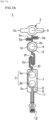
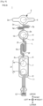
- FIG. 1A is a front view of the body electrode 1
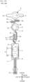
- FIG. 1B is a back view of the body electrode 1.
- the body electrode 1 is used to stimulate a nerve leading to a muscle of a body (a subject to which the body electrode 1 is attached), and to monitor the degree of relaxation of the reacting muscle based on a physiological signal of the muscle.
- the body electrode 1 is used in the case where the degree of relaxation of a muscle of a body is monitored by the TOF (Train of Four) method in which muscle stimulation is successively performed four times every 0.5 seconds, and the process of four successive muscle stimulations is repeated every 15 seconds.
- TOF Train of Four
- a stimulation electrode 3, an active electrode 4, a reference electrode 5, and a neutral electrode 6 are mounted on a base 2.
- the base 2 includes an upper island portion 2a on which the reference electrode 5 is mounted, an intermediate island portion 2b on which the active electrode 4 is mounted, a lower island portion 2c on which the stimulation electrode 3 and the neutral electrode 6 are mounted, a first connection portion 2d provided between the intermediate island portion 2b and the lower island portion 2c, and a second connection portion 2e provided between the upper island portion 2a and the intermediate island portion 2b.
- the first connection portion 2d has a first direction changing part 2f configured to change the direction in which the first connection portion 2d extends. Since the first connection portion 2d has the first direction changing part 2f, at least one of the distance and the angle between the stimulation electrode 3 and the active electrode 4 is adjustable.
- the second connection portion 2e has a second direction changing part 2g configured to change the direction in which the second connection portion 2e extends. Since the second connection portion 2e has the second direction changing part 2g, at least one of the distance and the angle between the active electrode 4 and the reference electrode 5 is adjustable.
- the first direction changing part 2f is configured to change the direction in which the first connection portion 2d extends in the longitudinal direction of the body electrode 1.
- the second direction changing part 2g is configured to change the direction in which the second connection portion 2e extends in the lateral direction of the body electrode 1. That is, the first direction changing part 2f and the second direction changing part 2g are configured to change the direction in which the first connection portion 2d extends and the direction in which the second connection portion 2e extends in different directions, respectively.
- the first direction changing part 2f is configured to change the direction in which the first connection portion 2d extends in the longitudinal direction of the body electrode 1 to prevent, when attaching the body electrode 1 to the subject, the first connection portion 2d from rising up and from contacting the wrist of the subject to stimulate the sensation of pain.
- the second direction changing part 2g is configured to change the direction in which the second connection portion 2e extends in the lateral direction of the body electrode 1 to prevent, when attaching the body electrode 1 the subject, the second connection portion 2e from rising up and from contacting the hypothenar to stimulate the sensation of pain.
- the stimulation electrode 3 is disposed at a position closer to a connector 12 in the longitudinal direction of the body electrode 1 as compared with the reference electrode 5, and is configured to apply electrical stimulation to a nerve leading to a muscle of the body (for example, the ulnar nerve).
- the stimulation electrode 3 includes a negative electrode 3a and a positive electrode 3b.
- the active electrode 4 is disposed between the stimulation electrode 3 and the reference electrode 5, and provided to detect a physiological signal from a muscle that responds to the electrical stimulation applied by the stimulation electrode 3.
- the active electrode 4 is configured by a cathode.
- the active electrode 4 is mounted corresponding to, for example, the abductor digiti minimi muscle.
- the reference electrode 5 is disposed at a position farther from the connector 12 in the longitudinal direction of the body electrode 2 with respect to the stimulation electrode 3 and the active electrode 4, and is configured to detect a physiological signal from a muscle that responds to the electrical stimulation applied by the stimulation electrode 3.
- the reference electrode 5 is a positive electrode.
- the reference electrode 5 is mounted corresponding to, for example, the abductor digiti minimi muscle.
- the neutral electrode 6 is provided to block noises flowing through the body electrode 1.
- the neutral electrode 6 is disposed proximal to the negative electrode 3a. More specifically, the neutral electrode 6 is mounted on an upper side of the negative electrode 3a. In other words, the neutral electrode 6 is mounted in a direction toward the active electrode 4 from the negative electrode 3a, or a direction toward the active electrode 4 from the connector 12. Furthermore, it can be said also that the neutral electrode 6 is mounted in a region between the negative electrode 3a and the active electrode 4. Therefore, noises that are generated in the case where the negative electrode 3a and the active electrode 4 are close to each other are easily blocked.
- a negative electrode wiring part 7 is provided to connect the negative electrode 3a and the connector 12 to each other. Based on an operation performed on an electric stimulator (not illustrated), therefore, the negative electrode 3a applies stimulation to the body through the negative electrode wiring part 7.
- a positive electrode wiring part 8 is provided to connect the positive electrode 3b and the connector 12 to each other. Based on an operation performed on the electric stimulator, therefore, the positive electrode 3b applies stimulation to the body through the positive electrode wiring part 8.
- An active electrode wiring part 9 is provided to connect the active electrode 4 and the connector 12 to each other. Based on a detection of a physiological signal of the living bode, therefore, the active electrode 4 outputs the physiological signal to the electric stimulator through the active electrode wiring part 9. A part of the active electrode wiring part 9 is arranged in the first connection portion 2d.
- a reference electrode wiring part 10 is provided to connect the reference electrode 5 and the connector 12 to each other. Based on a detection of a physiological signal of the living bode, therefore, the reference electrode 5 outputs the physiological signal to the electric stimulator through the reference electrode wiring part 10. A part of the reference electrode wiring part 10 is arranged in the second connection portion 2e.
- a neutral electrode wiring part 11 is provided to connect the neutral electrode 6 and the connector 12 to each other.
- the connector 12 is provided to connect the wiring parts respectively connected to the electrodes. Specifically, the negative electrode wiring part 7 connected to the negative electrode 3a, the positive electrode wiring part 8 connected to the positive electrode 3b, the active electrode wiring part 9 connected to the active electrode 4, the reference electrode wiring part 10 connected to the reference electrode 5, and the neutral electrode wiring part 11 connected to the neutral electrode 6 are connected to the connector 12.
- the connector 12 is further connected to the electric stimulator. Spare connecting parts that are not connected to any wiring part are disposed in the connector 12.
- An adhesive gel 13 is provided to attach the electrodes to the body, and covers the back sides of the electrodes.
- the adhesive gel 13 includes a negative electrode adhesive gel 13a that covers the back side of the negative electrode 3a, a positive electrode adhesive gel 13b that covers the back side of the positive electrode 3b, an active electrode adhesive gel 13c that covers the back side of the active electrode 4, a reference electrode adhesive gel 13d that covers the back side of the reference electrode 5; and a neutral electrode adhesive gel 13e that covers the back side of the neutral electrode 6.
- An adhesive tape 14 is provided to attach the body electrode 1 to a release sheet 100 that will be described later, and has an adhesiveness.
- the adhesive tape 14 has a configuration including: a stimulation electrode adhesive tape 14a that is disposed on the back side of the lower island portion 2c, and in the peripheries of the negative electrode adhesive gel 13a, the positive electrode 3b, and the neutral electrode adhesive gel 13e; an active electrode adhesive tape 14b that is disposed on the back side of the intermediate island portion 2b, and in the periphery of the active electrode adhesive gel 13c; and a reference electrode adhesive tape 14c that is disposed on the back side of the upper island portion 2a, and in the periphery of the reference electrode adhesive gel 13d.
- a configuration in which paste is attached to the upper island portion 2a, the intermediate island portion 2b, and the lower island portion 2c, and which is attached to the release sheet 100 may be employed. That is, it is requested only to perform a process so as to provide the upper island portion 2a, the intermediate island portion 2b, and the lower island portion 2c with an adhesiveness.
- adhesiveness means possession of a viscosity of a degree at which the portions are stuck and held to the release sheet 100 or the skin of the subject.
- An adhesive tape is not disposed on the back side of the first connection portion 2d, and that of the second connection portion 2e. That is, the back side of the first connection portion 2d, and that of the second connection portion 2e do not have an adhesiveness.
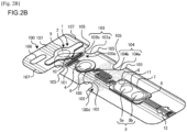
- FIG. 2A is an exploded perspective view of the body electrode unit U
- FIG. 2B is a perspective view of the body electrode unit U.
- the release sheet 100 is a sheet to which the body electrode 1 is to be attached, and can transmit light. During a process for producing the body electrode unit U, therefore, it is easily check whether the adhesive gel 13 is provided cover the back sides of the electrodes.
- the release sheet 100 has: an upper sheet portion 100a to which the reference electrode adhesive tape 14c of the upper island portion 2a is to be attached; an intermediate sheet portion 100b to which the active electrode adhesive tape 14b of the intermediate island portion 2b is to be attached; and a lower sheet portion 100c to which the stimulation electrode adhesive tape 14a of the lower island portion 2c is to be attached.
- the release sheet 100 includes a first processed part 101, a second processed part 102, a first notch 103, a second notch 104, rounded parts 105, a positioning hole 106, and patterned portions 107.
- a process for facilitating separation and/or bending of the upper sheet portion 100a and the intermediate sheet portion 100b is applied to the first processed part 101.
- a process for facilitating separation and/or bending of the intermediate sheet portion 100b and the lower sheet portion 100c is applied to the second processed part 102.
- a perforation process is performed in the first processed part 101 and the second processed part 102 as a mode in which the release sheet 100 can be separated and/or bent.
- the mode is not limited to this, and any mode may be used in so far as it can separate and/or bend the release sheet 100.
- a half-cut process in which a part of the thickness of the release sheet 100 is cut may be applied to the first processed part 101 and the second processed part 102.
- the cutting is performed at a predetermined thickness (e.g., about 50 ⁇ m) that is smaller than the thickness of the release sheet 100, thereby enabling the release sheet 100 to be separated and/or bent.
- the first processed part 101 may be disposed at any position in so far as it is in a first area 100d that, in the case where the body electrode 1 is attached to the release sheet 100, is between the lower end of the intermediate island portion 2b and the upper end of the lower island portion 2c.
- the second processed part 102 may be disposed at any position in so far as it is in a second area 100e that, in the case where the body electrode 1 is attached to the release sheet 100, is between the lower end of the upper island portion 2a and the upper end of the intermediate island portion 2b.
- the first notch 103 is disposed in the both side ends of the first processed part 101.
- the first notch 103 has a configuration including a first right notch 103a that is disposed in the right side end of the first processed part 101, and a first left notch 103b that is disposed in the left side end of the first processed part 101.
- Each of the notches has an approximately semicircular shape.
- the second notch 104 is disposed in the both side ends of the second processed part 102.
- the second notch 104 has a configuration including a second right notch 104a that is disposed in the right side end of the second processed part 102, and a second left notch 104b that is disposed in the left side end of the second processed part 102.
- Each of the notches has an approximately semicircular shape.
- the width of the first processed part 101 is smaller than that of the release sheet 100.
- the second notch 104 is disposed, the width of the second processed part 102 is smaller than that of the release sheet 100. Because of these, a situation can be prevented from occurring where, when the upper sheet portion 100a and the intermediate sheet portion 100b are to be separated from each other along the first processed part 101, or when the intermediate sheet portion 100b and the lower sheet portion 100c are to be separated from each other along the second processed part 102, the first connection portion 2d or the second connection portion 2e is stretched without slack during the course of the separation, and the release sheet 100 cannot be cut off up to the end.
- the shape of the first notch 103, and that of the second notch 104 are not limited to an approximately semicircular shape, and may be any shape in so far as it can make the width of the first processed part 101 smaller than that of the release sheet 100, and that of the second processed part 102 smaller than that of the release sheet 100.
- the rounded parts 105 are disposed in end parts of the first notch 103 and the second notch 104. Since the rounded parts 105 are disposed, here, a situation can be prevented from occurring where, when the release sheet 100 is to be cut off along the first processed part 101, or when the release sheet 100 is to be cut off along the second processed part 102, sharp edges are formed, and someone is injured.
- the positioning hole 106 is provided to fix the release sheet 100 during a process for producing the body electrode unit U.
- the patterned portions 107 are provided linearly in the longitudinal direction of the release sheet 100. Since the patterned portions 107 are disposed, the release sheet 100 can be easily recognized when it is transparent and is dropped on the floor. Therefore, it is possible to prevent someone from slipping by stepping on the release sheet 100.
- the patterned portions 107 may have any pattern in so far as the pattern enables the release sheet 100 to be easily recognized.
- the body electrode 1 is configured such that the stimulation electrode 3, the active electrode 4, and the reference electrode 5 are put together to form a single continuous shape.
- the intermediate island portion 2b where the active electrode 4 is mounted, and the lower island portion 2c where the stimulation electrode 3 is mounted are connected to each other by the first connection portion 2d.
- the upper island portion 2a where the reference electrode 5 is mounted, and the intermediate island portion 2b where the active electrode 4 is mounted are connected to each other by the second connection portion 2e. This is how the stimulation electrode 3, the active electrode 4, and the reference electrode 5 are put together to form a single continuous shape in this example.
- the body electrode 1 is attached to the release sheet 100.
- the release sheet 100 is first moved in the direction of the arrow Ar1 as illustrated in FIG. 4A , whereby the attaching between the lower sheet portion 100c and the stimulation electrode adhesive tape 14a is released.
- the release sheet 100 is peeled off in a range extending to the second processed part 102.
- the release sheet 100 is moved in the direction of the arrow Ar2, thereby bending the release sheet 100 along the second processed part 102.
- the lower sheet portion 100c may be separated from the release sheet 100 along the second processed part 102.
- the stimulation electrode adhesive tape 14a is attached so that the negative electrode adhesive gel 13a and the positive electrode adhesive gel 13b correspond to the ulnar nerve of the subject.
- the release sheet 100 is moved in the direction of the arrow Ar3, whereby the attaching between the intermediate sheet portion 100b and the active electrode adhesive tape 14b is released. As a result, the release sheet 100 is peeled off in a range extending to the first processed part 101.
- the release sheet 100 is moved in the direction of the arrow Ar4, thereby bending the release sheet 100 along the first processed part 101.
- the intermediate sheet portion 100b may be separated from the upper sheet portion 100a along the first processed part 101.
- the active electrode adhesive tape 14b is attached so that the active electrode adhesive gel 13c corresponds to the abductor digiti minimi muscle of the subject.
- the first direction changing part 2f that can change at least one of the distance and angle between the stimulation electrode 3 and the active electrode 4 is disposed in the first connection portion 2d, and therefore the first connection portion 2d elongates in the direction of the arrow Ar5.
- the release sheet 100 is moved in the direction of the arrow Ar6, whereby the attaching between the upper sheet portion 100a and the reference electrode adhesive tape 14c is released. As a result, the release sheet 100 is peeled off from the body electrode 1.
- the reference electrode adhesive tape 14c is attached so that the reference electrode adhesive gel 13d corresponds to the abductor digiti minimi muscle of the subject.
- the second direction changing part 2g that can change at least the distance and angle between the active electrode 4 and the reference electrode 5 is disposed in the second connection portion 2e, and therefore the second connection portion 2e elongates in the direction of the arrow Ar7.
- the first direction changing part 2f is disposed in the first connection portion 2d in the embodiment, and therefore the first connection portion 2d can elongate.
- the second direction changing part 2g is disposed in the second connection portion 2e in the embodiment, and therefore the second connection portion 2e can elongate. Because of these, in the body electrode 1 in which the stimulation electrode 3, the active electrode 4, and the reference electrode 5 are put together to form a single continuous shape, even in the case where the subject has a large hand, the lower island portion 2c where the stimulation electrode 3 is mounted, the intermediate island portion 2b where the active electrode 4 is mounted, and the upper island portion 2a where the reference electrode 5 is mounted can be attached to desired positions respectively.
- the body electrode 1 of the embodiment can be used not only while the lower island portion 2c where the stimulation electrode 3 is mounted, the intermediate island portion 2b where the active electrode 4 is mounted, and the upper island portion 2a where the reference electrode 5 is mounted are attached to the hand or arm of the subject, but also while these portions are attached to the foot of the subject.
- the first direction changing part 2f is disposed in the first connection portion 2d, and therefore the first connection portion 2d can be shortened.
- the second direction changing part 2g is disposed in the second connection portion 2e, and therefore the second connection portion 2e can be shortened. Because of these, in the body electrode 1 in which the stimulation electrode 3, the active electrode 4, and the reference electrode 5 put together to form a single continuous shape, even in the case where the subject has a small hand, the lower island portion 2c where the stimulation electrode 3 is mounted, the intermediate island portion 2b where the active electrode 4 is mounted, and the upper island portion 2a where the reference electrode 5 is mounted can be attached to desired positions.
- the negative electrode 3a configured by a cathode, and the active electrode 4 configured by a cathode are close to each other. Therefore, it may be considered that a detected physiological signal is made unstable by noises.
- the neutral electrode 6 is disposed proximal to the negative electrode 3a. Even in the case where the negative electrode 3a and the active electrode 4 are close to each other, therefore, noises can be efficiently blocked, and hence a detected physiological signal can be stabilized.
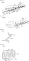
- FIG. 6A illustrates an example of the first connection portion 2d and the second connection portion 2e.
- each of the first direction changing part 2f and the second direction changing part 2g is disposed at two locations, and are configured to change the directions in which the first connection portion 2d and the second connection portion 2e extend in oblique directions.
- FIG. 6B illustrates another example of the first connection portion 2d and the second connection portion 2e.
- each of the first direction changing part 2f and the second direction changing part 2g is disposed at six locations, and are configured to change the first connection portion 2d and the second connection portion 2e in the longitudinal direction of the body electrode.
- FIG. 6C illustrates another example of the first connection portion 2d and the second connection portion 2e.
- each of the first direction changing part 2f and the second direction changing part 2g is disposed at one location, and are configured to change the direction in which the first connection portion 2d and the second connection portion 2ec extend in a rotational direction.
- the direction in which the first connection portion 2d is changed by the first direction changing part 2f, and the direction in which the second connection portion 2e is changed by the second direction changing part 2g can be adequately set.
- the number of the first direction changing part 2f that is provided in the first connection portion 2d is required to be at least one, and may be adequately set.
- the number of the second direction changing part 2g that is provided in the second connection portion 2e is required to be at least one, and may be adequately set.
- the neutral electrode 6 is disposed proximal to the negative electrode 3a.
- the position where the neutral electrode 6 is disposed can be adequately set in so far as noises flowing through the body electrode 1 can be blocked.
- a preferred example of the position where the neutral electrode 6 is disposed will be described.
- the neutral electrode 6 of this example is disposed at a position that is closer to the connector 12 as compared with the stimulation electrode 3.
- the distance with respect to the connector 12 is short, and therefore the neutral electrode wiring part 11 can be shortened. Consequently, the production cost can be reduced.
- the neutral electrode 6 In the case where the neutral electrode 6 is disposed in the upper island portion 2a or the intermediate island portion 2b, a part of the neutral electrode wiring part 11 must be disposed in the first connection portion 2d or the second connection portion 2e, and therefore it is required to thicken the first connection portion 2d or the second connection portion 2e. As a result, the production cost is raised by an amount corresponding to the thickened part of the first connection portion 2d or the second connection portion 2e. As compared with the case where the neutral electrode 6 is disposed in the upper island portion 2a or the intermediate island portion 2b, therefore, the production cost can be reduced.
- the timing Ta in FIG. 8 is a timing when a stimulation current has not flown through the body electrode 1.
- the stimulation current does not flow through the body electrode 1, and therefore there is no potential difference among the stimulation electrode 3, the active electrode 4, and the reference electrode 5.
- the timing Tb in FIG. 8 is a timing when the stimulation current begins to flow through the body electrode 1.
- a potential difference is produced between the negative electrode 3a and the positive electrode 3b.
- an impedance having a value that is a product of the stimulation current flowing through the body electrode 1, and the impedance between the negative electrode 3a and the positive electrode 3b is produced.
- the timing Tc in FIG. 8 is a timing when the stimulation current stops to flow through the body electrode 1.
- the flow of the stimulation current through the body electrode 1 is ended, electric charges are discharged from the active electrode 4 and the reference electrode 5 toward the negative electrode 3a.
- the timing Td in FIG. 8 is a timing when the detection of artifact noise is started.
- the rate of the discharge is inversely proportional to a CR time constant that is a product of the capacitance C and the resistance R.
- the impedances have a positive correlation with the distance on the surface of the living body.
- the neutral electrode 6 is mounted in a place remote from the negative electrode 3a, such as the position of the neutral electrode 6 in the example of FIGS. 7A and 7B , therefore, the impedance between the neutral electrode 6 and the negative electrode 3a is increased. Therefore, the amount of charges that are discharged through the internal circuit of the electric stimulator is reduced, and the rate of discharge becomes low, with the result that the level of artifact noise is increased. Because of these, the neutral electrode 6 is preferably mounted proximal to the negative electrode 3a from the view point of the reduction of artifact noise.
- the neutral electrode 6 When the neutral electrode 6 is mounted on a lower side of the negative electrode 3a and the positive electrode 3b, the charges are hardly separated into charges that are discharged from the active electrode 4 to the negative electrode 3a through the living body, and charges that are discharged from the neutral electrode 6 to the negative electrode 3a through the active electrode 4 and the internal circuit of the electric stimulator. It is desirable from this viewpoint that the neutral electrode 6 be mounted on an upper side of the negative electrode 3a and the positive electrode 3b than being mounted on the lower side of the negative electrode 3a and the positive electrode 3b.
- An electromyogram is measured after the timing Td. Specifically, the measurement of an electromyogram is started at a first timing that is after 1,200 ⁇ s, and ended at a second timing that is after the first timing.
- the neutral electrode 6 of this example is mounted in the lower island portion 2c. Moreover, the neutral electrode 6 is mounted on the upper side of the negative electrode 3a. As compared with the position where the neutral electrode 6 of FIGS. 7A and 7B is mounted, the neutral electrode 6 is mounted proximal to the negative electrode 3a.
- the impedance between the neutral electrode 6 and the negative electrode 3a is reduced.
- the amount of charges that are discharged through the internal circuit of the electric stimulator is increased, and the rate of discharge becomes high, with the result that artifact noise can be reduced.
- the neutral electrode 6 of this example is mounted on a line segment L connecting the center of the negative electrode 3a and the center of the active electrode 4. As compared with the body electrode 1 of the example of FIGS. 1A and 1B , therefore, the line connecting the center of the negative electrode 3a and the center of the neutral electrode 6 is shortened, and consequently the neutral electrode 6 is proximal to the negative electrode 3a.
- the impedance between the neutral electrode 6 and the negative electrode 3a is reduced.
- the amount of charges that are discharged through the internal circuit of the electric stimulator is increased, and the rate of discharge becomes high, with the result that artifact noise can be reduced.
- the neutral electrode 6 of this example is mounted on the upper side of the negative electrode 3a and in the intermediate island portion 2b.
- the neutral electrode 6 is mounted on the line segment L connecting the center of the negative electrode 3a and the center of the active electrode 4.
- the neutral electrode 6 is mounted in the intermediate island portion 2b and in a place other than that on the line segment L, therefore, the line connecting the center of the negative electrode 3a and the center of the neutral electrode 6 is shortened, and consequently the neutral electrode 6 is proximal to the negative electrode 3a.
- the impedance between the neutral electrode 6 and the negative electrode 3a is reduced.
- the amount of charges that are discharged through the internal circuit of the electric stimulator is increased, and the rate of discharge becomes high, with the result that artifact noise can be reduced.
- the body electrode 1 of FIG. 11A has a right island portion 2h disposed on the right side of the first connection portion 2d.
- the neutral electrode 6 is mounted in the right island portion 2h.
- the neutral electrode 6 is mounted on an upper side of the negative electrode 3a. According to this configuration, artifact noise that is produced in the body electrode 1 can be reduced.
- the neutral electrode 6 is mounted in the right island portion 2h that is located between the negative electrode 3a and the active electrode 4, and therefore artifact noise that is produced in the body electrode 1 can be reduced as compared with the case where the neutral electrode 6 is mounted in a region other than the region between the negative electrode 3a and the active electrode 4.
- a left island portion 2i may be disposed on the left side of the first connection portion 2d, and the neutral electrode 6 may be mounted in the left island portion 2i.
- the neutral electrode 6 is mounted on the upper side of the negative electrode 3a, and therefore artifact noise that is produced in the body electrode 1 can be reduced.
- the neutral electrode 6 is mounted in the left island portion 2i, it can be said that the neutral electrode 6 is mounted in the region between the negative electrode 3a and the active electrode 4, and therefore artifact noise that is produced in the body electrode 1 can be reduced as compared with the case where the neutral electrode 6 is mounted in a region other than the region between the negative electrode 3a and the active electrode 4.
- the stimulation electrode 3, the active electrode 4, and the reference electrode 5 are mounted so that a straight line connects their centers.
- the stimulation electrode 3, the active electrode 4, and the reference electrode 5 may be mounted such that they are deviated in the lateral direction of the body electrode 1.
- the reference electrode 5 is mounted in the upper island portion 2a, and the active electrode 4 is mounted in the intermediate island portion 2b.
- the active electrode 4 may be mounted on the upper island portion 2a, and the reference electrode 5 may be mounted on the intermediate island portion 2b.
- the negative electrode 3a is disposed at a position that is remoter from the connector 12 with respect to the positive electrode 3b, and the positive electrode 3b is disposed at a position that is closer to the connector 12 with respect to the negative electrode 3a.
- the position where the positive electrode 3b is mounted and the position where the negative electrode 3a is mounted may be reversed.
- the first direction changing part 2f changes the direction in which the first connection portion 2d extends in the longitudinal direction of the body electrode 1
- the direction in which the first connection portion 2d extends may be changed in the lateral direction of the body electrode 1.
- the second direction changing part 2g changes the direction in which the second connection portion 2e extends in the lateral direction
- the direction in which the second connection portion 2e extends may be changed in the longitudinal direction.
- the first direction changing part 2f and the second direction changing part 2g change the directions of the first connection portion 2d and the second connection portion 2e in different directions, respectively, the directions of the first connection portion 2d and the second connection portion 2e may be changed in the same direction.
- a perforation process and a half-cut process have been described as specific examples of the first processed part 101 and the second processed part 102, the presently disclosed subject matter is not limited to this.
- a spot fixing process in which the both ends of the first processed part 101 and the second processed part 102 are spot-fixed, and the spot-fixed ends are separated from each other may be applied.
- a cut may be provided at least one side of the first processed part 101 and the second processed part 102.
- the first processed part 101 and the second processed part 102 employ the same process as a mode in which the release sheet 100 can be separated and/or bent
- the parts may employ different processes.
- the first processed part 101 may employ a perforation process
- the second processed part 102 may employ a half-cut process.
- the first processed part 101 and the second processed part 102 enable the release sheet 100 to be separated and/or bent in a horizontal direction
- the presently disclosed subject matter is not limited to this.
- the release sheet 100 may be separated and/or bent in any direction.
- the first processed part 101 and the second processed part 102 may have a mode in which the release sheet 100 can be separated and/or bent in an oblique direction.
- first notch 103 and the second notch 104 are disposed in the respective both side ends, the presently disclosed subject matter is not limited to this.
- the first notch 103 and the second notch 104 may be disposed in only one side, i.e., the right side end or the left side end.
- the electrodes and the electric stimulator are connected to each other through the respective wiring parts, the electrodes and the electric stimulator may be connected to each other through a wireless function.
- the way the body electrode unit U is used is not limited to the example illustrated in FIGS. 4A to 5D . That is, as described in the following examples, the body electrode unit U may be used in different ways. Thus, it is possible to provide options for a medical person in using the body electrode unit U.
- the lower sheet portion 100c is separated along the first processed part 101, the lower island portion 2c is peeled off from the lower sheet portion 100c, and the stimulation electrode adhesive tape 14a is attached to the subject.
- the intermediate sheet portion 100b is separated along the second processed part 102, the intermediate island portion 2b is peeled off from the intermediate sheet portion 100b, and the active electrode adhesive tape 14b is attached to the subject.
- the upper island portion 2a is peeled off from the upper sheet portion 100a, and the reference electrode adhesive tape 14c is attached to the subject.
- the upper island portion 2a is peeled off from the upper sheet portion 100a, the release sheet 100 is bent along the second processed part 102, and the reference electrode adhesive tape 14c is attached to the subject.
- the intermediate island portion 2b is peeled off from the intermediate sheet portion 100b, the release sheet 100 is bent along the first processed part 101, and the active electrode adhesive tape 14b is attached to the subject.
- the lower island portion 2c is peeled off from the lower sheet portion 100c, and the stimulation electrode adhesive tape 14a is attached to the subject.
- the upper sheet portion 100a is separated along the second processed part 102, the upper island portion 2a is peeled off from the upper sheet portion 100a, and the reference electrode adhesive tape 14c is attached to the subject.
- the intermediate sheet portion 100b is separated along the first processed part 101, the intermediate island portion 2b is peeled off from the intermediate sheet portion 100b, and the active electrode adhesive tape 14b is attached to the subject.
- the lower island portion 2c is peeled off from the lower sheet portion 100c, and the stimulation electrode adhesive tape 14a is attached to the subject.
- the body electrode 1 includes the stimulation electrode 3, the active electrode 4, and the reference electrode 5.
- the first connection portion 2d is disposed between the stimulation electrode 3 and the active electrode 4, and the second connection portion 2e is disposed between the active electrode 4 and the reference electrode 5.
- the first connection portion 2d has the first direction changing part 2f configured to change the direction in which the first connection portion 2d extends, so that at least one of the distance and the angle between the stimulation electrode 3 and the active electrode 4 is adjustable. According to the configuration, the first connection portion 2d can be elongated and shortened. Therefore, it is possible to provide a body electrode and body electrode unit in which an electrode can be attached to a desired position.
- a body electrode includes a first electrode (for example, the stimulation electrode 3) configured to stimulate a muscle of a body, a second electrode (for example, the active electrode 4) and a third electrode (for example, the reference electrode 5) configured to detect a physiological signal from the muscle that is stimulated by the first electrode, a first connection portion (for example, the first connection portion 2d) arranged between the first electrode and the second electrode, and a second connection portion (for example, the second connection portion 2e) arranged between the third electrode and one of the first electrode and the second electrode.
- a first electrode for example, the stimulation electrode 3
- a second electrode for example, the active electrode
- a third electrode for example, the reference electrode 5
- a first connection portion for example, the first connection portion 2d
- a second connection portion for example, the second connection portion 2e
- the first connection portion has at least one first direction changing part (for example, the first direction changing part 2f) configured to change a direction in which the first connection portion extends, such that at least one of a distance and an angle between the first electrode and the second electrode is adjustable.
- the at least one first direction changing part is configured to allow a movement of the second electrode relative to the first electrode, the movement of the second electrode including at least one of a linear movement and a rotational movement.
- the second connection portion may have at least one second direction changing part (for example, the second direction changing parts 2g) configured to change a direction in which the second connection portion extends, such that at least one of a distance and an angle between the third electrode and the one of the first electrode and the second electrode is adjustable.
- the at least one second direction changing part is configured to allow a movement of the third electrode relative to the one of the first electrode and the second electrode, the movement of the third electrode including at least one of a linear movement and a rotational movement.
- the first electrode, the second electrode, and the third electrode may be arranged in a row.
- the first direction changing part and the second direction changing part may be configured to change the direction in which the first connection portion extends and the direction in which the second connection portion extends in different directions.
- the first direction changing part may be configured to change the direction in which the first connection portion extends in a longitudinal direction of the body electrode
- the second direction changing part may be configured to change the direction in which the second connection portion extends in a lateral direction of the body electrode
- the body electrode may further include a first electrode mounting portion (for example, the lower island portion 2c) having an adhesiveness and on which the first electrode is mounted, a second electrode mounting portion (for example, the intermediate island portion 2b) having an adhesiveness and on which the second electrode is mounted, and a third electrode mounting portion (for example, the upper island portion 2a) having an adhesiveness and on which the third electrode is mounted.
- the first connection portion connects the first electrode mounting portion and the second electrode mounting portion to each other, and does not have an adhesiveness.
- the second connection portion connects the second electrode mounting portion and the third electrode mounting portion to each other, and does not have an adhesiveness.
- the first electrode mounting portion may include a neutral electrode (for example, the neutral electrode 6) configured to eliminate a noise flowing through the body electrode.
- a neutral electrode for example, the neutral electrode 6
- the first electrode may include a negative electrode (for example, the negative electrode 3a) and a positive electrode (for example, the positive electrode 3b), and the neutral electrode may be mounted closer to the negative electrode than to the positive electrode.
- the first electrode may include a negative electrode (for example, the negative electrode 3a), and a positive electrode (for example, the positive electrode 3b), and the neutral electrode may be mounted on an upper side of the negative electrode.
- the neutral electrode may be mounted between the negative electrode and the second electrode.
- the neutral electrode may be mounted on a line segment (for example, the line segment L) connecting the center of the negative electrode and the center of the second electrode.
- a body electrode unit includes the body electrode (for example, the body electrode 1), and a release sheet (for example, the release sheet 100) to which the body electrode is attached.
Landscapes
- Health & Medical Sciences (AREA)
- Life Sciences & Earth Sciences (AREA)
- Engineering & Computer Science (AREA)
- Biomedical Technology (AREA)
- Animal Behavior & Ethology (AREA)
- General Health & Medical Sciences (AREA)
- Public Health (AREA)
- Veterinary Medicine (AREA)
- Heart & Thoracic Surgery (AREA)
- Biophysics (AREA)
- Physics & Mathematics (AREA)
- Pathology (AREA)
- Medical Informatics (AREA)
- Molecular Biology (AREA)
- Surgery (AREA)
- Radiology & Medical Imaging (AREA)
- Nuclear Medicine, Radiotherapy & Molecular Imaging (AREA)
- Dermatology (AREA)
- Electrotherapy Devices (AREA)
- Measurement And Recording Of Electrical Phenomena And Electrical Characteristics Of The Living Body (AREA)
Description
- The presently disclosed subject matter relates to a body electrode and body electrode unit configured to be used in measurement of physiological information.
- A related art body electrode is provided in a state where a face on which an adhesive gel is disposed is attached to a release sheet. When using the body electrode, the body electrode is peeled off from the release sheet, the face on which the adhesive gel is disposed is attached to a body (a subject).
- The body electrode may have a plurality of electrodes mounted on the surface of a substrate sheet (see, e.g., JPH09-313454A). In such a body electrode, the plurality of electrodes are mounted on the one substrate sheet while being separated from one another. Therefore, the body electrode can be attached to a body while maintaining predetermined intervals.
- In such a body electrode, however, the plurality of electrodes are pattern-printed to the one substrate sheet. That is, the electrodes are mounted at fixed positions, respectively. With this configuration, when attaching the body electrode to a hand of a subject, for example, the body electrode may not be attached to a desired position depending on the size of the hand of the subject.
US 2014/0235991 discloses an electrode system for use with neuromuscular monitoring systems. - The invention is defined by the
independent claim 1. Illustrative aspects of the presently disclosed subject matter provide a body electrode and body electrode unit in which an electrode can be attached to a desired position. - According to an aspect of the presently disclosed subject matter, a body electrode includes a first electrode configured to stimulate a muscle of a body, a second electrode, and a third electrode. The second electrode and the third electrode are configured to detect a physiological signal from the muscle that is stimulated by the first electrode. The body electrode also includes a first connection portion arranged between the first electrode and the second electrode, and a second connection portion arranged between the third electrode and one of the first electrode and the second electrode. The first connection portion has at least one first direction changing part configured to change a direction in which the first connection portion extends, such that at least one of a distance and an angle between the first electrode and the second electrode is adjustable.
- According to another aspect of the presently disclosed subject matter, a body electrode unit includes the body electrode and a release sheet to which the body electrode is attached.
-
- [
fig.1A] FIG. 1A is a view illustrating a front side a body electrode. - [
fig.1B] FIG. 1B is a view illustrating a back side a body electrode. - [
fig.2A] FIG. 2A is a view illustrating a body electrode unit. - [
fig.2B] FIG. 2B is another view illustrating a body electrode unit. - [
fig.3] FIG. 3 is a view illustrating a lateral side of the body electrode unit. - [
fig.4A] FIG. 4A is a view illustrating how the body electrode unit is used. - [
fig.4B] FIG. 4B is another view illustrating how the body electrode unit is used. - [
fig.4C] FIG. 4C is another view illustrating how the body electrode unit is used. - [
fig.4D] FIG. 4D is another view illustrating how the body electrode unit is used. - [
fig.5A] FIG. 5A is another view illustrating how the body electrode unit is used. - [
fig.5B] FIG. 5B is another view illustrating how the body electrode unit is used. - [
fig.5C] FIG. 5C is another view illustrating how the body electrode unit is used. - [
fig.5D] FIG. 5D is another view illustrating how the body electrode unit is used. - [
fig.6A] FIG. 6A is a view illustrating an example of first and second connection portions. - [
fig.6B] FIG. 6B is a view illustrating another example of first and second connection portions. - [
fig.6C] FIG. 6C is a view illustrating another example of first and second connection portions. - [
fig.7A] FIG. 7A is a view illustrating an example a neutral electrode. - [
fig.7B] FIG. 7B is another view illustrating the example the neutral electrode. - [
fig.8] FIG. 8 is a view illustrating a potential waveform of an active electrode. - [
fig.9] FIG. 9 is a view illustrating another example the neutral electrode. - [
fig.10] FIG. 10 is a view illustrating yet another example the neutral electrode. - [
fig.11A] FIG. 11A is a view illustrating yet another example the neutral electrode. - [
fig.11B] FIG. 11B is a view illustrating yet another example of the neutral electrode. - Hereinafter, embodiments of the presently disclosed subject matter will be described with reference to the drawings.
- First, a structure of a
body electrode 1 will be described with reference toFIGS. 1A and1B .FIG. 1A is a front view of thebody electrode 1, andFIG. 1B is a back view of thebody electrode 1. - In this example, the
body electrode 1 is used to stimulate a nerve leading to a muscle of a body (a subject to which thebody electrode 1 is attached), and to monitor the degree of relaxation of the reacting muscle based on a physiological signal of the muscle. For example, thebody electrode 1 is used in the case where the degree of relaxation of a muscle of a body is monitored by the TOF (Train of Four) method in which muscle stimulation is successively performed four times every 0.5 seconds, and the process of four successive muscle stimulations is repeated every 15 seconds. - A
stimulation electrode 3, anactive electrode 4, areference electrode 5, and aneutral electrode 6 are mounted on abase 2. Thebase 2 includes anupper island portion 2a on which thereference electrode 5 is mounted, anintermediate island portion 2b on which theactive electrode 4 is mounted, alower island portion 2c on which thestimulation electrode 3 and theneutral electrode 6 are mounted, afirst connection portion 2d provided between theintermediate island portion 2b and thelower island portion 2c, and asecond connection portion 2e provided between theupper island portion 2a and theintermediate island portion 2b. - The
first connection portion 2d has a firstdirection changing part 2f configured to change the direction in which thefirst connection portion 2d extends. Since thefirst connection portion 2d has the firstdirection changing part 2f, at least one of the distance and the angle between thestimulation electrode 3 and theactive electrode 4 is adjustable. - The
second connection portion 2e has a seconddirection changing part 2g configured to change the direction in which thesecond connection portion 2e extends. Since thesecond connection portion 2e has the seconddirection changing part 2g, at least one of the distance and the angle between theactive electrode 4 and thereference electrode 5 is adjustable. - The first
direction changing part 2f is configured to change the direction in which thefirst connection portion 2d extends in the longitudinal direction of thebody electrode 1. The seconddirection changing part 2g is configured to change the direction in which thesecond connection portion 2e extends in the lateral direction of thebody electrode 1. That is, the firstdirection changing part 2f and the seconddirection changing part 2g are configured to change the direction in which thefirst connection portion 2d extends and the direction in which thesecond connection portion 2e extends in different directions, respectively. - The first
direction changing part 2f is configured to change the direction in which thefirst connection portion 2d extends in the longitudinal direction of thebody electrode 1 to prevent, when attaching thebody electrode 1 to the subject, thefirst connection portion 2d from rising up and from contacting the wrist of the subject to stimulate the sensation of pain. - The second
direction changing part 2g is configured to change the direction in which thesecond connection portion 2e extends in the lateral direction of thebody electrode 1 to prevent, when attaching thebody electrode 1 the subject, thesecond connection portion 2e from rising up and from contacting the hypothenar to stimulate the sensation of pain. - The
stimulation electrode 3 is disposed at a position closer to aconnector 12 in the longitudinal direction of thebody electrode 1 as compared with thereference electrode 5, and is configured to apply electrical stimulation to a nerve leading to a muscle of the body (for example, the ulnar nerve). Thestimulation electrode 3 includes anegative electrode 3a and apositive electrode 3b. - The
active electrode 4 is disposed between thestimulation electrode 3 and thereference electrode 5, and provided to detect a physiological signal from a muscle that responds to the electrical stimulation applied by thestimulation electrode 3. In the embodiment, theactive electrode 4 is configured by a cathode. Here, theactive electrode 4 is mounted corresponding to, for example, the abductor digiti minimi muscle. - The
reference electrode 5 is disposed at a position farther from theconnector 12 in the longitudinal direction of thebody electrode 2 with respect to thestimulation electrode 3 and theactive electrode 4, and is configured to detect a physiological signal from a muscle that responds to the electrical stimulation applied by thestimulation electrode 3. In the embodiment, thereference electrode 5 is a positive electrode. Here, thereference electrode 5 is mounted corresponding to, for example, the abductor digiti minimi muscle. - The
neutral electrode 6 is provided to block noises flowing through thebody electrode 1. Theneutral electrode 6 is disposed proximal to thenegative electrode 3a. More specifically, theneutral electrode 6 is mounted on an upper side of thenegative electrode 3a. In other words, theneutral electrode 6 is mounted in a direction toward theactive electrode 4 from thenegative electrode 3a, or a direction toward theactive electrode 4 from theconnector 12. Furthermore, it can be said also that theneutral electrode 6 is mounted in a region between thenegative electrode 3a and theactive electrode 4. Therefore, noises that are generated in the case where thenegative electrode 3a and theactive electrode 4 are close to each other are easily blocked. - A negative
electrode wiring part 7 is provided to connect thenegative electrode 3a and theconnector 12 to each other. Based on an operation performed on an electric stimulator (not illustrated), therefore, thenegative electrode 3a applies stimulation to the body through the negativeelectrode wiring part 7. - A positive
electrode wiring part 8 is provided to connect thepositive electrode 3b and theconnector 12 to each other. Based on an operation performed on the electric stimulator, therefore, thepositive electrode 3b applies stimulation to the body through the positiveelectrode wiring part 8. - An active
electrode wiring part 9 is provided to connect theactive electrode 4 and theconnector 12 to each other. Based on a detection of a physiological signal of the living bode, therefore, theactive electrode 4 outputs the physiological signal to the electric stimulator through the activeelectrode wiring part 9. A part of the activeelectrode wiring part 9 is arranged in thefirst connection portion 2d. - A reference
electrode wiring part 10 is provided to connect thereference electrode 5 and theconnector 12 to each other. Based on a detection of a physiological signal of the living bode, therefore, thereference electrode 5 outputs the physiological signal to the electric stimulator through the referenceelectrode wiring part 10. A part of the referenceelectrode wiring part 10 is arranged in thesecond connection portion 2e. - A neutral
electrode wiring part 11 is provided to connect theneutral electrode 6 and theconnector 12 to each other. - The
connector 12 is provided to connect the wiring parts respectively connected to the electrodes. Specifically, the negativeelectrode wiring part 7 connected to thenegative electrode 3a, the positiveelectrode wiring part 8 connected to thepositive electrode 3b, the activeelectrode wiring part 9 connected to theactive electrode 4, the referenceelectrode wiring part 10 connected to thereference electrode 5, and the neutralelectrode wiring part 11 connected to theneutral electrode 6 are connected to theconnector 12. Theconnector 12 is further connected to the electric stimulator. Spare connecting parts that are not connected to any wiring part are disposed in theconnector 12. - An
adhesive gel 13 is provided to attach the electrodes to the body, and covers the back sides of the electrodes. Specifically, theadhesive gel 13 includes a negative electrodeadhesive gel 13a that covers the back side of thenegative electrode 3a, a positive electrodeadhesive gel 13b that covers the back side of thepositive electrode 3b, an active electrodeadhesive gel 13c that covers the back side of theactive electrode 4, a referenceelectrode adhesive gel 13d that covers the back side of thereference electrode 5; and a neutral electrodeadhesive gel 13e that covers the back side of theneutral electrode 6. - An
adhesive tape 14 is provided to attach thebody electrode 1 to arelease sheet 100 that will be described later, and has an adhesiveness. As illustrated inFIG. 1B , theadhesive tape 14 has a configuration including: a stimulation electrodeadhesive tape 14a that is disposed on the back side of thelower island portion 2c, and in the peripheries of the negative electrodeadhesive gel 13a, thepositive electrode 3b, and the neutral electrodeadhesive gel 13e; an active electrodeadhesive tape 14b that is disposed on the back side of theintermediate island portion 2b, and in the periphery of the active electrodeadhesive gel 13c; and a reference electrodeadhesive tape 14c that is disposed on the back side of theupper island portion 2a, and in the periphery of the referenceelectrode adhesive gel 13d. - In place of the
adhesive tape 14, for example, a configuration in which paste is attached to theupper island portion 2a, theintermediate island portion 2b, and thelower island portion 2c, and which is attached to therelease sheet 100 may be employed. That is, it is requested only to perform a process so as to provide theupper island portion 2a, theintermediate island portion 2b, and thelower island portion 2c with an adhesiveness. Here, "adhesiveness" means possession of a viscosity of a degree at which the portions are stuck and held to therelease sheet 100 or the skin of the subject. - An adhesive tape is not disposed on the back side of the
first connection portion 2d, and that of thesecond connection portion 2e. That is, the back side of thefirst connection portion 2d, and that of thesecond connection portion 2e do not have an adhesiveness. When the stimulation electrodeadhesive tape 14a, the active electrodeadhesive tape 14b, and the reference electrodeadhesive tape 14c are to be attached to the subject, therefore, a situation where the tapes are attached to unintended positions can be prevented from occurring. - Referring to
FIGS. 2A and2B , next, a body electrode unit U will be described.FIG. 2A is an exploded perspective view of the body electrode unit U, andFIG. 2B is a perspective view of the body electrode unit U. - As illustrated in
FIG. 2A , the body electrode unit U has thebody electrode 1 that has been described with reference toFIGS. 1A and1B , and therelease sheet 100. - The
release sheet 100 is a sheet to which thebody electrode 1 is to be attached, and can transmit light. During a process for producing the body electrode unit U, therefore, it is easily check whether theadhesive gel 13 is provided cover the back sides of the electrodes. - The
release sheet 100 has: anupper sheet portion 100a to which the reference electrodeadhesive tape 14c of theupper island portion 2a is to be attached; an intermediate sheet portion 100b to which the active electrodeadhesive tape 14b of theintermediate island portion 2b is to be attached; and alower sheet portion 100c to which the stimulation electrodeadhesive tape 14a of thelower island portion 2c is to be attached. Therelease sheet 100 includes a first processedpart 101, a second processedpart 102, afirst notch 103, asecond notch 104,rounded parts 105, apositioning hole 106, and patternedportions 107. - A process for facilitating separation and/or bending of the
upper sheet portion 100a and the intermediate sheet portion 100b is applied to the first processedpart 101. - A process for facilitating separation and/or bending of the intermediate sheet portion 100b and the
lower sheet portion 100c is applied to the second processedpart 102. - In the embodiment, a perforation process is performed in the first processed
part 101 and the second processedpart 102 as a mode in which therelease sheet 100 can be separated and/or bent. However, the mode is not limited to this, and any mode may be used in so far as it can separate and/or bend therelease sheet 100. For example, a half-cut process in which a part of the thickness of therelease sheet 100 is cut may be applied to the first processedpart 101 and the second processedpart 102. In the thickness (e.g., about 75 µm) of therelease sheet 100, specifically, the cutting is performed at a predetermined thickness (e.g., about 50 µm) that is smaller than the thickness of therelease sheet 100, thereby enabling therelease sheet 100 to be separated and/or bent. - In the embodiment, the first processed
part 101 may be disposed at any position in so far as it is in afirst area 100d that, in the case where thebody electrode 1 is attached to therelease sheet 100, is between the lower end of theintermediate island portion 2b and the upper end of thelower island portion 2c. In the same or similar manner, the second processedpart 102 may be disposed at any position in so far as it is in asecond area 100e that, in the case where thebody electrode 1 is attached to therelease sheet 100, is between the lower end of theupper island portion 2a and the upper end of theintermediate island portion 2b. - The
first notch 103 is disposed in the both side ends of the first processedpart 101. In the embodiment, as illustrated inFIGS. 2A and2B , thefirst notch 103 has a configuration including a firstright notch 103a that is disposed in the right side end of the first processedpart 101, and a firstleft notch 103b that is disposed in the left side end of the first processedpart 101. Each of the notches has an approximately semicircular shape. - The
second notch 104 is disposed in the both side ends of the second processedpart 102. In the embodiment, as illustrated inFIGS. 2A and2B , thesecond notch 104 has a configuration including a secondright notch 104a that is disposed in the right side end of the second processedpart 102, and a secondleft notch 104b that is disposed in the left side end of the second processedpart 102. Each of the notches has an approximately semicircular shape. - Since the
first notch 103 is disposed, the width of the first processedpart 101 is smaller than that of therelease sheet 100. In the same or similar manner, since thesecond notch 104 is disposed, the width of the second processedpart 102 is smaller than that of therelease sheet 100. Because of these, a situation can be prevented from occurring where, when theupper sheet portion 100a and the intermediate sheet portion 100b are to be separated from each other along the first processedpart 101, or when the intermediate sheet portion 100b and thelower sheet portion 100c are to be separated from each other along the second processedpart 102, thefirst connection portion 2d or thesecond connection portion 2e is stretched without slack during the course of the separation, and therelease sheet 100 cannot be cut off up to the end. - The shape of the
first notch 103, and that of thesecond notch 104 are not limited to an approximately semicircular shape, and may be any shape in so far as it can make the width of the first processedpart 101 smaller than that of therelease sheet 100, and that of the second processedpart 102 smaller than that of therelease sheet 100. - The
rounded parts 105 are disposed in end parts of thefirst notch 103 and thesecond notch 104. Since therounded parts 105 are disposed, here, a situation can be prevented from occurring where, when therelease sheet 100 is to be cut off along the first processedpart 101, or when therelease sheet 100 is to be cut off along the second processedpart 102, sharp edges are formed, and someone is injured. - The
positioning hole 106 is provided to fix therelease sheet 100 during a process for producing the body electrode unit U. - The
patterned portions 107 are provided linearly in the longitudinal direction of therelease sheet 100. Since the patternedportions 107 are disposed, therelease sheet 100 can be easily recognized when it is transparent and is dropped on the floor. Therefore, it is possible to prevent someone from slipping by stepping on therelease sheet 100. Thepatterned portions 107 may have any pattern in so far as the pattern enables therelease sheet 100 to be easily recognized. - Referring to
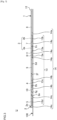
Fig. 3 , next, a side view of the body electrode unit U will be described. - As illustrated in
FIG. 3 , thebody electrode 1 is configured such that thestimulation electrode 3, theactive electrode 4, and thereference electrode 5 are put together to form a single continuous shape. Specifically, theintermediate island portion 2b where theactive electrode 4 is mounted, and thelower island portion 2c where thestimulation electrode 3 is mounted are connected to each other by thefirst connection portion 2d. Theupper island portion 2a where thereference electrode 5 is mounted, and theintermediate island portion 2b where theactive electrode 4 is mounted are connected to each other by thesecond connection portion 2e. This is how thestimulation electrode 3, theactive electrode 4, and thereference electrode 5 are put together to form a single continuous shape in this example. - Referring to
FIGS. 4 and5 , next, a use mode of the body electrode unit U will be described. - As described above, the
body electrode 1 is attached to therelease sheet 100. In the case where thebody electrode 1 is to be used, therefore, therelease sheet 100 is first moved in the direction of the arrow Ar1 as illustrated inFIG. 4A , whereby the attaching between thelower sheet portion 100c and the stimulation electrodeadhesive tape 14a is released. As a result, therelease sheet 100 is peeled off in a range extending to the second processedpart 102. - As illustrated in
FIG. 4B , next, therelease sheet 100 is moved in the direction of the arrow Ar2, thereby bending therelease sheet 100 along the second processedpart 102. In the case where the second processedpart 102 is configured by tearable perforations, although not illustrated, thelower sheet portion 100c may be separated from therelease sheet 100 along the second processedpart 102. - As illustrated in
FIG. 4C , next, the stimulation electrodeadhesive tape 14a is attached so that the negative electrodeadhesive gel 13a and the positive electrodeadhesive gel 13b correspond to the ulnar nerve of the subject. - As illustrated in
FIG. 4D , next, therelease sheet 100 is moved in the direction of the arrow Ar3, whereby the attaching between the intermediate sheet portion 100b and the active electrodeadhesive tape 14b is released. As a result, therelease sheet 100 is peeled off in a range extending to the first processedpart 101. - As illustrated in
FIG. 5A , next, therelease sheet 100 is moved in the direction of the arrow Ar4, thereby bending therelease sheet 100 along the first processedpart 101. In the case where the first processedpart 101 is configured by tearable perforations, although not illustrated, the intermediate sheet portion 100b may be separated from theupper sheet portion 100a along the first processedpart 101. - As illustrated in
FIG. 5B , next, the active electrodeadhesive tape 14b is attached so that the active electrodeadhesive gel 13c corresponds to the abductor digiti minimi muscle of the subject. - At this time, the first
direction changing part 2f that can change at least one of the distance and angle between thestimulation electrode 3 and theactive electrode 4 is disposed in thefirst connection portion 2d, and therefore thefirst connection portion 2d elongates in the direction of the arrow Ar5. - As illustrated in
FIG. 5C , next, therelease sheet 100 is moved in the direction of the arrow Ar6, whereby the attaching between theupper sheet portion 100a and the reference electrodeadhesive tape 14c is released. As a result, therelease sheet 100 is peeled off from thebody electrode 1. - As illustrated in
FIG. 5D , next, the reference electrodeadhesive tape 14c is attached so that the referenceelectrode adhesive gel 13d corresponds to the abductor digiti minimi muscle of the subject. - At this time, the second
direction changing part 2g that can change at least the distance and angle between theactive electrode 4 and thereference electrode 5 is disposed in thesecond connection portion 2e, and therefore thesecond connection portion 2e elongates in the direction of the arrow Ar7. - As described above, the first
direction changing part 2f is disposed in thefirst connection portion 2d in the embodiment, and therefore thefirst connection portion 2d can elongate. Moreover, the seconddirection changing part 2g is disposed in thesecond connection portion 2e in the embodiment, and therefore thesecond connection portion 2e can elongate. Because of these, in thebody electrode 1 in which thestimulation electrode 3, theactive electrode 4, and thereference electrode 5 are put together to form a single continuous shape, even in the case where the subject has a large hand, thelower island portion 2c where thestimulation electrode 3 is mounted, theintermediate island portion 2b where theactive electrode 4 is mounted, and theupper island portion 2a where thereference electrode 5 is mounted can be attached to desired positions respectively. - Since the
first connection portion 2d can elongate, and thesecond connection portion 2e can elongate, thebody electrode 1 of the embodiment can be used not only while thelower island portion 2c where thestimulation electrode 3 is mounted, theintermediate island portion 2b where theactive electrode 4 is mounted, and theupper island portion 2a where thereference electrode 5 is mounted are attached to the hand or arm of the subject, but also while these portions are attached to the foot of the subject. - On the other hand, also in the case where the
body electrode 1 in which thestimulation electrode 3, theactive electrode 4, and thereference electrode 5 are put together to form a single continuous shape is used in a subject having a small hand, there is a problem in that thestimulation electrode 3, theactive electrode 4, and thereference electrode 5 are hardly attached to desired positions. - In the embodiment, by contrast, the first
direction changing part 2f is disposed in thefirst connection portion 2d, and therefore thefirst connection portion 2d can be shortened. In the embodiment, furthermore, the seconddirection changing part 2g is disposed in thesecond connection portion 2e, and therefore thesecond connection portion 2e can be shortened. Because of these, in thebody electrode 1 in which thestimulation electrode 3, theactive electrode 4, and thereference electrode 5 put together to form a single continuous shape, even in the case where the subject has a small hand, thelower island portion 2c where thestimulation electrode 3 is mounted, theintermediate island portion 2b where theactive electrode 4 is mounted, and theupper island portion 2a where thereference electrode 5 is mounted can be attached to desired positions. - In the case where the subject has a small hand, when the
first connection portion 2d is shortened by the firstdirection changing part 2f, thenegative electrode 3a configured by a cathode, and theactive electrode 4 configured by a cathode are close to each other. Therefore, it may be considered that a detected physiological signal is made unstable by noises. However, theneutral electrode 6 is disposed proximal to thenegative electrode 3a. Even in the case where thenegative electrode 3a and theactive electrode 4 are close to each other, therefore, noises can be efficiently blocked, and hence a detected physiological signal can be stabilized. - Referring to
FIGS. 6A to 6C , other examples of thefirst connection portion 2d and thesecond connection portion 2e will be described. -
FIG. 6A illustrates an example of thefirst connection portion 2d and thesecond connection portion 2e. In this example, in thefirst connection portion 2d and thesecond connection portion 2e, each of the firstdirection changing part 2f and the seconddirection changing part 2g is disposed at two locations, and are configured to change the directions in which thefirst connection portion 2d and thesecond connection portion 2e extend in oblique directions. -
FIG. 6B illustrates another example of thefirst connection portion 2d and thesecond connection portion 2e. In this example, in thefirst connection portion 2d and thesecond connection portion 2e, each of the firstdirection changing part 2f and the seconddirection changing part 2g is disposed at six locations, and are configured to change thefirst connection portion 2d and thesecond connection portion 2e in the longitudinal direction of the body electrode. -
FIG. 6C illustrates another example of thefirst connection portion 2d and thesecond connection portion 2e. In this example, in thefirst connection portion 2d and thesecond connection portion 2e, each of the firstdirection changing part 2f and the seconddirection changing part 2g is disposed at one location, and are configured to change the direction in which thefirst connection portion 2d and the second connection portion 2ec extend in a rotational direction. - As described above, the direction in which the
first connection portion 2d is changed by the firstdirection changing part 2f, and the direction in which thesecond connection portion 2e is changed by the seconddirection changing part 2g can be adequately set. - The number of the first
direction changing part 2f that is provided in thefirst connection portion 2d is required to be at least one, and may be adequately set. - In the same or similar manner, the number of the second
direction changing part 2g that is provided in thesecond connection portion 2e is required to be at least one, and may be adequately set. - Referring to
FIGS. 7A and7B , next, another example of theneutral electrode 6 will be described. - In the above-described embodiment, the
neutral electrode 6 is disposed proximal to thenegative electrode 3a. However, the position where theneutral electrode 6 is disposed can be adequately set in so far as noises flowing through thebody electrode 1 can be blocked. Hereinafter, a preferred example of the position where theneutral electrode 6 is disposed will be described. - As illustrated in
FIGS. 7A and7B , theneutral electrode 6 of this example is disposed at a position that is closer to theconnector 12 as compared with thestimulation electrode 3. The distance with respect to theconnector 12 is short, and therefore the neutralelectrode wiring part 11 can be shortened. Consequently, the production cost can be reduced. - In the case where the
neutral electrode 6 is disposed in theupper island portion 2a or theintermediate island portion 2b, a part of the neutralelectrode wiring part 11 must be disposed in thefirst connection portion 2d or thesecond connection portion 2e, and therefore it is required to thicken thefirst connection portion 2d or thesecond connection portion 2e. As a result, the production cost is raised by an amount corresponding to the thickened part of thefirst connection portion 2d or thesecond connection portion 2e. As compared with the case where theneutral electrode 6 is disposed in theupper island portion 2a or theintermediate island portion 2b, therefore, the production cost can be reduced. - Next, the potential waveform of the
active electrode 4 will be described with reference toFIG. 8 . - First, the timing Ta in
FIG. 8 is a timing when a stimulation current has not flown through thebody electrode 1. Here, although impedances exist among thestimulation electrode 3, theactive electrode 4, and thereference electrode 5, the stimulation current does not flow through thebody electrode 1, and therefore there is no potential difference among thestimulation electrode 3, theactive electrode 4, and thereference electrode 5. - Next, the timing Tb in
FIG. 8 is a timing when the stimulation current begins to flow through thebody electrode 1. When the stimulation current flows through thebody electrode 1, a potential difference is produced between thenegative electrode 3a and thepositive electrode 3b. Specifically, an impedance having a value that is a product of the stimulation current flowing through thebody electrode 1, and the impedance between thenegative electrode 3a and thepositive electrode 3b is produced. - When the
body electrode 1 is attached to the living body as illustrated inFIG. 5D , potential differences are produced also between thenegative electrode 3a and theactive electrode 4, and between thenegative electrode 3a and thereference electrode 5 through the impedances in and under the skin. The potential differences are produced during the time period when the stimulation current is caused to flow (specifically, the time period between the timing Tb and the timing Tc). - Next, the timing Tc in
FIG. 8 is a timing when the stimulation current stops to flow through thebody electrode 1. When the flow of the stimulation current through thebody electrode 1 is ended, electric charges are discharged from theactive electrode 4 and thereference electrode 5 toward thenegative electrode 3a. - Next, the timing Td in
FIG. 8 is a timing when the detection of artifact noise is started. The shorter the discharging time period when electric charges are discharged from theactive electrode 4 and thereference electrode 5 toward thenegative electrode 3a, the lower the level of artifact noise. - The rate of the discharge is inversely proportional to a CR time constant that is a product of the capacitance C and the resistance R. When the
neutral electrode 6 is mounted proximal to theactive electrode 4 and thereference electrode 5, therefore, the charges are separated into charges that are discharged from theactive electrode 4 to thenegative electrode 3a through the living body, and those that are discharged from theneutral electrode 6 to thenegative electrode 3a through theactive electrode 4 and the internal circuit of the electric stimulator. - The impedances have a positive correlation with the distance on the surface of the living body. When the
neutral electrode 6 is mounted in a place remote from thenegative electrode 3a, such as the position of theneutral electrode 6 in the example ofFIGS. 7A and7B , therefore, the impedance between theneutral electrode 6 and thenegative electrode 3a is increased. Therefore, the amount of charges that are discharged through the internal circuit of the electric stimulator is reduced, and the rate of discharge becomes low, with the result that the level of artifact noise is increased. Because of these, theneutral electrode 6 is preferably mounted proximal to thenegative electrode 3a from the view point of the reduction of artifact noise. - When the
neutral electrode 6 is mounted on a lower side of thenegative electrode 3a and thepositive electrode 3b, the charges are hardly separated into charges that are discharged from theactive electrode 4 to thenegative electrode 3a through the living body, and charges that are discharged from theneutral electrode 6 to thenegative electrode 3a through theactive electrode 4 and the internal circuit of the electric stimulator. It is desirable from this viewpoint that theneutral electrode 6 be mounted on an upper side of thenegative electrode 3a and thepositive electrode 3b than being mounted on the lower side of thenegative electrode 3a and thepositive electrode 3b. - An electromyogram is measured after the timing Td. Specifically, the measurement of an electromyogram is started at a first timing that is after 1,200 µs, and ended at a second timing that is after the first timing.
- Next, another example of the
neutral electrode 6 will be described with reference toFIG. 9 . - As illustrated in
FIG. 9 , theneutral electrode 6 of this example is mounted in thelower island portion 2c. Moreover, theneutral electrode 6 is mounted on the upper side of thenegative electrode 3a. As compared with the position where theneutral electrode 6 ofFIGS. 7A and7B is mounted, theneutral electrode 6 is mounted proximal to thenegative electrode 3a. - As compared with the case where the
neutral electrode 6 is mounted on the lower side of thenegative electrode 3a and thepositive electrode 3b, therefore, the impedance between theneutral electrode 6 and thenegative electrode 3a is reduced. The amount of charges that are discharged through the internal circuit of the electric stimulator is increased, and the rate of discharge becomes high, with the result that artifact noise can be reduced. - The
neutral electrode 6 of this example is mounted on a line segment L connecting the center of thenegative electrode 3a and the center of theactive electrode 4. As compared with thebody electrode 1 of the example ofFIGS. 1A and1B , therefore, the line connecting the center of thenegative electrode 3a and the center of theneutral electrode 6 is shortened, and consequently theneutral electrode 6 is proximal to thenegative electrode 3a. - As compared with the case where the
neutral electrode 6 is not mounted on the line segment L connecting the center of thenegative electrode 3a and the center of theactive electrode 4, therefore, the impedance between theneutral electrode 6 and thenegative electrode 3a is reduced. The amount of charges that are discharged through the internal circuit of the electric stimulator is increased, and the rate of discharge becomes high, with the result that artifact noise can be reduced. - Next, another example of the
neutral electrode 6 will be described with reference toFIG. 10 . - As illustrated in
FIG. 10 , theneutral electrode 6 of this example is mounted on the upper side of thenegative electrode 3a and in theintermediate island portion 2b. Theneutral electrode 6 is mounted on the line segment L connecting the center of thenegative electrode 3a and the center of theactive electrode 4. - As compared with the case where the
neutral electrode 6 is mounted in theintermediate island portion 2b and in a place other than that on the line segment L, therefore, the line connecting the center of thenegative electrode 3a and the center of theneutral electrode 6 is shortened, and consequently theneutral electrode 6 is proximal to thenegative electrode 3a. - Therefore, the impedance between the
neutral electrode 6 and thenegative electrode 3a is reduced. The amount of charges that are discharged through the internal circuit of the electric stimulator is increased, and the rate of discharge becomes high, with the result that artifact noise can be reduced. - As indicated in the examples of
FIGS. 9 and10 , when theneutral electrode 6 is mounted on the upper side of thenegative electrode 3a and thepositive electrode 3b, and on the line segment L, artifact noise can be efficiently reduced as compared with the case where theneutral electrode 6 is mounted at another position. - Next, another example of the
neutral electrode 6 will be described with reference toFIGS. 11A and11B . - The
body electrode 1 ofFIG. 11A has aright island portion 2h disposed on the right side of thefirst connection portion 2d. Theneutral electrode 6 is mounted in theright island portion 2h. In other words, theneutral electrode 6 is mounted on an upper side of thenegative electrode 3a. According to this configuration, artifact noise that is produced in thebody electrode 1 can be reduced. In thebody electrode 1 of the fourth modification, theneutral electrode 6 is mounted in theright island portion 2h that is located between thenegative electrode 3a and theactive electrode 4, and therefore artifact noise that is produced in thebody electrode 1 can be reduced as compared with the case where theneutral electrode 6 is mounted in a region other than the region between thenegative electrode 3a and theactive electrode 4. - As illustrated in
FIG. 11B , alternatively, aleft island portion 2i may be disposed on the left side of thefirst connection portion 2d, and theneutral electrode 6 may be mounted in theleft island portion 2i. Also in this case, in the same or similar manner as thebody electrode 1 illustrated inFIG. 11A , theneutral electrode 6 is mounted on the upper side of thenegative electrode 3a, and therefore artifact noise that is produced in thebody electrode 1 can be reduced. Also in the case where theneutral electrode 6 is mounted in theleft island portion 2i, it can be said that theneutral electrode 6 is mounted in the region between thenegative electrode 3a and theactive electrode 4, and therefore artifact noise that is produced in thebody electrode 1 can be reduced as compared with the case where theneutral electrode 6 is mounted in a region other than the region between thenegative electrode 3a and theactive electrode 4. - Other examples will be described below.
- In the
body electrode 1 of the above-described embodiment, thestimulation electrode 3, theactive electrode 4, and thereference electrode 5 are mounted so that a straight line connects their centers. However, thestimulation electrode 3, theactive electrode 4, and thereference electrode 5 may be mounted such that they are deviated in the lateral direction of thebody electrode 1. - In the
body electrode 1 of the above-described embodiment, thereference electrode 5 is mounted in theupper island portion 2a, and theactive electrode 4 is mounted in theintermediate island portion 2b. Alternatively, theactive electrode 4 may be mounted on theupper island portion 2a, and thereference electrode 5 may be mounted on theintermediate island portion 2b. - In the
body electrode 1 of the above-described embodiment, thenegative electrode 3a is disposed at a position that is remoter from theconnector 12 with respect to thepositive electrode 3b, and thepositive electrode 3b is disposed at a position that is closer to theconnector 12 with respect to thenegative electrode 3a. Alternatively, the position where thepositive electrode 3b is mounted and the position where thenegative electrode 3a is mounted may be reversed. - Although, in the above-described embodiment, the first
direction changing part 2f changes the direction in which thefirst connection portion 2d extends in the longitudinal direction of thebody electrode 1, the direction in which thefirst connection portion 2d extends may be changed in the lateral direction of thebody electrode 1. Likewise, although the seconddirection changing part 2g changes the direction in which thesecond connection portion 2e extends in the lateral direction, the direction in which thesecond connection portion 2e extends may be changed in the longitudinal direction. - Although, in the above-described embodiment, the first
direction changing part 2f and the seconddirection changing part 2g change the directions of thefirst connection portion 2d and thesecond connection portion 2e in different directions, respectively, the directions of thefirst connection portion 2d and thesecond connection portion 2e may be changed in the same direction. - Although, in the above-described embodiment, a perforation process and a half-cut process have been described as specific examples of the first processed
part 101 and the second processedpart 102, the presently disclosed subject matter is not limited to this. For example, a spot fixing process in which the both ends of the first processedpart 101 and the second processedpart 102 are spot-fixed, and the spot-fixed ends are separated from each other may be applied. Alternatively, a cut may be provided at least one side of the first processedpart 101 and the second processedpart 102. - Although, in the above-described embodiment, the first processed
part 101 and the second processedpart 102 employ the same process as a mode in which therelease sheet 100 can be separated and/or bent, the parts may employ different processes. For example, the first processedpart 101 may employ a perforation process, and the second processedpart 102 may employ a half-cut process. - Although, in the above-described embodiment, the first processed
part 101 and the second processedpart 102 enable therelease sheet 100 to be separated and/or bent in a horizontal direction, the presently disclosed subject matter is not limited to this. Therelease sheet 100 may be separated and/or bent in any direction. For example, the first processedpart 101 and the second processedpart 102 may have a mode in which therelease sheet 100 can be separated and/or bent in an oblique direction. - Although, in the above-described embodiment, the
first notch 103 and thesecond notch 104 are disposed in the respective both side ends, the presently disclosed subject matter is not limited to this. Thefirst notch 103 and thesecond notch 104 may be disposed in only one side, i.e., the right side end or the left side end. - Although, in the above-described embodiment, the electrodes and the electric stimulator are connected to each other through the respective wiring parts, the electrodes and the electric stimulator may be connected to each other through a wireless function.
- The way the body electrode unit U is used is not limited to the example illustrated in
FIGS. 4A to 5D . That is, as described in the following examples, the body electrode unit U may be used in different ways. Thus, it is possible to provide options for a medical person in using the body electrode unit U. - According to a first example, first, the
lower sheet portion 100c is separated along the first processedpart 101, thelower island portion 2c is peeled off from thelower sheet portion 100c, and the stimulation electrodeadhesive tape 14a is attached to the subject. Next, the intermediate sheet portion 100b is separated along the second processedpart 102, theintermediate island portion 2b is peeled off from the intermediate sheet portion 100b, and the active electrodeadhesive tape 14b is attached to the subject. Then, theupper island portion 2a is peeled off from theupper sheet portion 100a, and the reference electrodeadhesive tape 14c is attached to the subject. - According to a second example, first, the
upper island portion 2a is peeled off from theupper sheet portion 100a, therelease sheet 100 is bent along the second processedpart 102, and the reference electrodeadhesive tape 14c is attached to the subject. Next, theintermediate island portion 2b is peeled off from the intermediate sheet portion 100b, therelease sheet 100 is bent along the first processedpart 101, and the active electrodeadhesive tape 14b is attached to the subject. Then, thelower island portion 2c is peeled off from thelower sheet portion 100c, and the stimulation electrodeadhesive tape 14a is attached to the subject. - According to a third example, first, the
upper sheet portion 100a is separated along the second processedpart 102, theupper island portion 2a is peeled off from theupper sheet portion 100a, and the reference electrodeadhesive tape 14c is attached to the subject. Next, the intermediate sheet portion 100b is separated along the first processedpart 101, theintermediate island portion 2b is peeled off from the intermediate sheet portion 100b, and the active electrodeadhesive tape 14b is attached to the subject. Then, thelower island portion 2c is peeled off from thelower sheet portion 100c, and the stimulation electrodeadhesive tape 14a is attached to the subject. - As described above, the
body electrode 1 includes thestimulation electrode 3, theactive electrode 4, and thereference electrode 5. Thefirst connection portion 2d is disposed between thestimulation electrode 3 and theactive electrode 4, and thesecond connection portion 2e is disposed between theactive electrode 4 and thereference electrode 5. Thefirst connection portion 2d has the firstdirection changing part 2f configured to change the direction in which thefirst connection portion 2d extends, so that at least one of the distance and the angle between thestimulation electrode 3 and theactive electrode 4 is adjustable. According to the configuration, thefirst connection portion 2d can be elongated and shortened. Therefore, it is possible to provide a body electrode and body electrode unit in which an electrode can be attached to a desired position. - According to an aspect of the embodiments described above, a body electrode includes a first electrode (for example, the stimulation electrode 3) configured to stimulate a muscle of a body, a second electrode (for example, the active electrode 4) and a third electrode (for example, the reference electrode 5) configured to detect a physiological signal from the muscle that is stimulated by the first electrode, a first connection portion (for example, the
first connection portion 2d) arranged between the first electrode and the second electrode, and a second connection portion (for example, thesecond connection portion 2e) arranged between the third electrode and one of the first electrode and the second electrode. The first connection portion has at least one first direction changing part (for example, the firstdirection changing part 2f) configured to change a direction in which the first connection portion extends, such that at least one of a distance and an angle between the first electrode and the second electrode is adjustable. In other words, the at least one first direction changing part is configured to allow a movement of the second electrode relative to the first electrode, the movement of the second electrode including at least one of a linear movement and a rotational movement. - According to another aspect of the embodiments described above, the second connection portion may have at least one second direction changing part (for example, the second
direction changing parts 2g) configured to change a direction in which the second connection portion extends, such that at least one of a distance and an angle between the third electrode and the one of the first electrode and the second electrode is adjustable. In other words, the at least one second direction changing part is configured to allow a movement of the third electrode relative to the one of the first electrode and the second electrode, the movement of the third electrode including at least one of a linear movement and a rotational movement. - According to another aspect of the embodiments described above, the first electrode, the second electrode, and the third electrode may be arranged in a row.
- According to another aspect of the embodiments described above, the first direction changing part and the second direction changing part may be configured to change the direction in which the first connection portion extends and the direction in which the second connection portion extends in different directions.
- According to another aspect of the embodiments described above, the first direction changing part may be configured to change the direction in which the first connection portion extends in a longitudinal direction of the body electrode, and the second direction changing part may be configured to change the direction in which the second connection portion extends in a lateral direction of the body electrode.
- According to another aspect of the embodiments described above, the body electrode may further include a first electrode mounting portion (for example, the
lower island portion 2c) having an adhesiveness and on which the first electrode is mounted, a second electrode mounting portion (for example, theintermediate island portion 2b) having an adhesiveness and on which the second electrode is mounted, and a third electrode mounting portion (for example, theupper island portion 2a) having an adhesiveness and on which the third electrode is mounted. The first connection portion connects the first electrode mounting portion and the second electrode mounting portion to each other, and does not have an adhesiveness. The second connection portion connects the second electrode mounting portion and the third electrode mounting portion to each other, and does not have an adhesiveness. - According to another aspect of the embodiments described above, the first electrode mounting portion may include a neutral electrode (for example, the neutral electrode 6) configured to eliminate a noise flowing through the body electrode.
- According to another aspect of the embodiments described above, the first electrode may include a negative electrode (for example, the
negative electrode 3a) and a positive electrode (for example, thepositive electrode 3b), and the neutral electrode may be mounted closer to the negative electrode than to the positive electrode. - According to another aspect of the embodiments described above, the first electrode may include a negative electrode (for example, the
negative electrode 3a), and a positive electrode (for example, thepositive electrode 3b), and the neutral electrode may be mounted on an upper side of the negative electrode. - According to another aspect of the embodiments described above, the neutral electrode may be mounted between the negative electrode and the second electrode.
- According to another aspect of the embodiments described above, the neutral electrode may be mounted on a line segment (for example, the line segment L) connecting the center of the negative electrode and the center of the second electrode.
- According to another aspect of the embodiments described above, a body electrode unit includes the body electrode (for example, the body electrode 1), and a release sheet (for example, the release sheet 100) to which the body electrode is attached.
- The invention is set out in the
independent claim 1. Preferred embodiments are set out in the dependent claims.
Claims (12)
- A body electrode (1) comprising:a first electrode (3) configured to stimulate a muscle of a body;a second electrode (4) and a third electrode (5), the second electrode and the third electrode being configured to detect a physiological signal from the muscle that is stimulated by the first electrode;a first connection portion (2d) arranged between the first electrode and the second electrode; anda second connection (2e) portion arranged between the third electrode and one of the first electrode and the second electrode,wherein the first connection portion comprises at least one first direction changing part (2f) configured to change a direction in which the first connection portion extends in a longitudinal direction of the body electrode, such that a distance and an angle between the first electrode and the second electrode is adjustable.
- The body electrode according to claim 1, wherein the second connection portion comprises at least one second direction changing part (2g) configured to change a direction in which the second connection portion extends, such that at least one of a distance and an angle between the third electrode and the one of the first electrode and the second electrode is adjustable.
- The body electrode according to claim 1 or 2, wherein the first electrode, the second electrode, and the third electrode are arranged in a row.
- The body electrode according to claim 2, wherein the first direction changing part and the second direction changing part are configured to change the direction in which the first connection portion extends and the direction in which the second connection portion extends in different directions.
- The body electrode according to claim 4, wherein the first direction changing part is configured to change the direction in which the first connection portion extends in a longitudinal direction of the body electrode, and
wherein the second direction changing part is configured to change the direction in which the second connection portion extends in a lateral direction of the body electrode. - The body electrode according to any one of claims 1 to 5, further comprising:a first electrode mounting portion (2c) on which the first electrode is mounted, the first electrode mounting portion being adhesive;a second electrode mounting portion (2b) on which the second electrode is mounted, the second electrode mounting portion being adhesive; anda third electrode mounting portion (2a) on which the third electrode is mounted, the third electrode mounting portion being adhesive,wherein the first connection portion connects the first electrode mounting portion and the second electrode mounting portion to each other, the first connection portion being non-adhesiveness, andwherein the second connection portion connects the second electrode mounting portion and the third electrode mounting portion to each other, the second connection portion being non-adhesive.
- The body electrode according to claim 6, wherein the first electrode mounting portion comprises a neutral electrode (6) configured to eliminate a noise flowing through the body electrode.
- The body electrode according to claim 7, wherein the first electrode comprises a negative electrode (3a) and a positive electrode (3b), the neutral electrode being closer to the negative electrode than to the positive electrode.
- The body electrode according to claim 7, wherein the first electrode comprises a negative electrode and a positive electrode, the neutral electrode being mounted on an upper side of the negative electrode.
- The body electrode according to claim 9, wherein the neutral electrode is mounted between the negative electrode and the second electrode.
- The body electrode according to claim 9 or 10, wherein the neutral electrode is mounted on a line segment connecting a center of the negative electrode and a center of the second electrode.
- A body electrode unit comprising:the body electrode according to any one of claims 1 to 11; anda release sheet (100) to which the body electrode is attached.
Applications Claiming Priority (3)
| Application Number | Priority Date | Filing Date | Title |
|---|---|---|---|
| JP2019183802 | 2019-10-04 | ||
| JP2020157337A JP7520657B2 (en) | 2019-10-04 | 2020-09-18 | Bioelectrode and bioelectrode unit |
| PCT/JP2020/037346 WO2021066077A1 (en) | 2019-10-04 | 2020-09-30 | Body electrode and body electrode unit |
Publications (2)
| Publication Number | Publication Date |
|---|---|
| EP4037755A1 EP4037755A1 (en) | 2022-08-10 |
| EP4037755B1 true EP4037755B1 (en) | 2024-07-17 |
Family
ID=72896031
Family Applications (1)
| Application Number | Title | Priority Date | Filing Date |
|---|---|---|---|
| EP20792759.1A Active EP4037755B1 (en) | 2019-10-04 | 2020-09-30 | Body electrode and body electrode unit |
Country Status (4)
| Country | Link |
|---|---|
| US (1) | US20220323014A1 (en) |
| EP (1) | EP4037755B1 (en) |
| CN (1) | CN114502236B (en) |
| WO (1) | WO2021066077A1 (en) |
Families Citing this family (2)
| Publication number | Priority date | Publication date | Assignee | Title |
|---|---|---|---|---|
| JP7767288B2 (en) | 2019-12-23 | 2025-11-11 | アリメトリー リミテッド | Electrode Patch and Connection System |
| JP2024007673A (en) * | 2022-07-06 | 2024-01-19 | 日本光電工業株式会社 | Stimulation system, stimulation electrode unit, relay cable, and stimulation control device |
Family Cites Families (13)
| Publication number | Priority date | Publication date | Assignee | Title |
|---|---|---|---|---|
| JP3320306B2 (en) * | 1996-05-29 | 2002-09-03 | 積水化成品工業株式会社 | Method for manufacturing multipolar bioelectrode |
| US7628761B2 (en) * | 1997-07-01 | 2009-12-08 | Neurometrix, Inc. | Apparatus and method for performing nerve conduction studies with localization of evoked responses |
| GB2368017B (en) * | 2000-06-20 | 2004-05-12 | Bournemouth University Higher | Apparatus for electrical stimulation of the leg |
| US20070129771A1 (en) * | 2005-04-20 | 2007-06-07 | Kurtz Ronald L | Device, method and stimulus unit for testing neuromuscular function |
| US20100210965A1 (en) * | 2009-02-13 | 2010-08-19 | Gozani Shai N | Apparatus and method for the detection of neuromuscular signals |
| US9901273B2 (en) * | 2012-07-04 | 2018-02-27 | I Medex Co., Ltd. | Bioelectrode |
| JP2016508400A (en) * | 2013-02-15 | 2016-03-22 | アカシア・デザインズ・ベスローテン・フェンノートシャップ | Electrode system for use in medical monitoring systems |
| JP2017006644A (en) * | 2015-06-17 | 2017-01-12 | 株式会社 Mtg | Muscle electrostimulator |
| JP6746300B2 (en) * | 2015-11-30 | 2020-08-26 | 株式会社リコー | Neurostimulator, biomagnetic field measurement system |
| JP7152845B2 (en) * | 2017-04-27 | 2022-10-13 | 株式会社 Mtg | muscle electrostimulator |
| JP2019183802A (en) | 2018-04-17 | 2019-10-24 | 株式会社日立製作所 | Wind generator system |
| JP7272840B2 (en) | 2019-03-26 | 2023-05-12 | コマツ産機株式会社 | punch press machine |
| JP7446757B2 (en) * | 2019-10-04 | 2024-03-11 | 日本光電工業株式会社 | Bioelectrode unit |
-
2020
- 2020-09-30 US US17/754,440 patent/US20220323014A1/en active Pending
- 2020-09-30 WO PCT/JP2020/037346 patent/WO2021066077A1/en not_active Ceased
- 2020-09-30 EP EP20792759.1A patent/EP4037755B1/en active Active
- 2020-09-30 CN CN202080070274.1A patent/CN114502236B/en active Active
Also Published As
| Publication number | Publication date |
|---|---|
| US20220323014A1 (en) | 2022-10-13 |
| EP4037755A1 (en) | 2022-08-10 |
| CN114502236B (en) | 2025-12-09 |
| CN114502236A (en) | 2022-05-13 |
| WO2021066077A1 (en) | 2021-04-08 |
Similar Documents
| Publication | Publication Date | Title |
|---|---|---|
| EP4037561B1 (en) | Body electrode unit | |
| EP1552785B1 (en) | Body surface bio-potential sensor having multiple electrodes and apparatus comprising the body surface bio-potential sensor | |
| US6024702A (en) | Implantable electrode manufactured with flexible printed circuit | |
| CA2154773A1 (en) | Intravascular sensing device | |
| EP0855168A1 (en) | ECG electrode strip with elongated slots | |
| US20070185409A1 (en) | Method and system for determining an operable stimulus intensity for nerve conduction testing | |
| JP5767434B2 (en) | Electrode set for patient monitoring device | |
| WO2021066077A1 (en) | Body electrode and body electrode unit | |
| EP0509689A2 (en) | Multiple electrode strip | |
| KR102683830B1 (en) | Biosignal Measurement Patch Structure and Its Use Method | |
| KR20100039617A (en) | A flexible, multi-channel microelectrode for recording laboratory animal eeg and method for recording laboratory animal eeg using the same | |
| US20140142410A1 (en) | Nerve Stimulation Electrodes | |
| US20100210965A1 (en) | Apparatus and method for the detection of neuromuscular signals | |
| KR101785287B1 (en) | Microneedle electrode patch and fabrication method of the microneedle electrode patch | |
| WO2019126340A1 (en) | Disposable sensor for neuromuscular transmission measurement | |
| WO2010135463A2 (en) | Method and apparatus for neural signal determination and therapy enhancement | |
| US20240041411A1 (en) | Bio-signal measuring device and method of using the same | |
| EP2033575B1 (en) | Method for continuously or step by step manufacturing of biomedical multiple electrodes for single use, and matrix electrode system consisting of same | |
| JP2021058579A (en) | Bioelectrode and bioelectrode unit | |
| WO2003089062A1 (en) | Method and device for maintaining wakefulness and preventing undesired sleep | |
| ITTO20060584A1 (en) | SYSTEM AND METHOD OF ACQUISITION OF BIOELECTRIC SIGNALS THROUGH SKIN ELECTRODES | |
| US20200069213A1 (en) | Electrode apparatus and method for using the same | |
| US7079884B1 (en) | Biomedical electrode having a mating configuration and its associated method of application to the body | |
| US20230113963A1 (en) | Neuromuscular transmission monitoring system and kinemyography sensor | |
| KR20160091474A (en) | Dry electrode sensor for excellent ventilation |
Legal Events
| Date | Code | Title | Description |
|---|---|---|---|
| STAA | Information on the status of an ep patent application or granted ep patent |
Free format text: STATUS: UNKNOWN |
|
| STAA | Information on the status of an ep patent application or granted ep patent |
Free format text: STATUS: THE INTERNATIONAL PUBLICATION HAS BEEN MADE |
|
| PUAI | Public reference made under article 153(3) epc to a published international application that has entered the european phase |
Free format text: ORIGINAL CODE: 0009012 |
|
| STAA | Information on the status of an ep patent application or granted ep patent |
Free format text: STATUS: REQUEST FOR EXAMINATION WAS MADE |
|
| 17P | Request for examination filed |
Effective date: 20220325 |
|
| AK | Designated contracting states |
Kind code of ref document: A1 Designated state(s): AL AT BE BG CH CY CZ DE DK EE ES FI FR GB GR HR HU IE IS IT LI LT LU LV MC MK MT NL NO PL PT RO RS SE SI SK SM TR |
|
| DAV | Request for validation of the european patent (deleted) | ||
| DAX | Request for extension of the european patent (deleted) | ||
| STAA | Information on the status of an ep patent application or granted ep patent |
Free format text: STATUS: EXAMINATION IS IN PROGRESS |
|
| 17Q | First examination report despatched |
Effective date: 20230707 |
|
| RIC1 | Information provided on ipc code assigned before grant |
Ipc: A61B 5/00 20060101ALI20230703BHEP Ipc: A61B 5/389 20210101ALI20230703BHEP Ipc: A61B 5/266 20210101ALI20230703BHEP Ipc: A61B 5/259 20210101ALI20230703BHEP Ipc: A61B 5/0531 20210101ALI20230703BHEP Ipc: A61N 1/36 20060101ALI20230703BHEP Ipc: A61N 1/04 20060101AFI20230703BHEP |
|
| GRAP | Despatch of communication of intention to grant a patent |
Free format text: ORIGINAL CODE: EPIDOSNIGR1 |
|
| STAA | Information on the status of an ep patent application or granted ep patent |
Free format text: STATUS: GRANT OF PATENT IS INTENDED |
|
| INTG | Intention to grant announced |
Effective date: 20240220 |
|
| GRAS | Grant fee paid |
Free format text: ORIGINAL CODE: EPIDOSNIGR3 |
|
| GRAA | (expected) grant |
Free format text: ORIGINAL CODE: 0009210 |
|
| STAA | Information on the status of an ep patent application or granted ep patent |
Free format text: STATUS: THE PATENT HAS BEEN GRANTED |
|
| AK | Designated contracting states |
Kind code of ref document: B1 Designated state(s): AL AT BE BG CH CY CZ DE DK EE ES FI FR GB GR HR HU IE IS IT LI LT LU LV MC MK MT NL NO PL PT RO RS SE SI SK SM TR |
|
| REG | Reference to a national code |
Ref country code: CH Ref legal event code: EP |
|
| REG | Reference to a national code |
Ref country code: DE Ref legal event code: R096 Ref document number: 602020034200 Country of ref document: DE |
|
| REG | Reference to a national code |
Ref country code: IE Ref legal event code: FG4D |
|
| REG | Reference to a national code |
Ref country code: LT Ref legal event code: MG9D |
|
| REG | Reference to a national code |
Ref country code: NL Ref legal event code: MP Effective date: 20240717 |
|
| PG25 | Lapsed in a contracting state [announced via postgrant information from national office to epo] |
Ref country code: PT Free format text: LAPSE BECAUSE OF FAILURE TO SUBMIT A TRANSLATION OF THE DESCRIPTION OR TO PAY THE FEE WITHIN THE PRESCRIBED TIME-LIMIT Effective date: 20241118 |
|
| REG | Reference to a national code |
Ref country code: AT Ref legal event code: MK05 Ref document number: 1703575 Country of ref document: AT Kind code of ref document: T Effective date: 20240717 |
|
| PG25 | Lapsed in a contracting state [announced via postgrant information from national office to epo] |
Ref country code: NL Free format text: LAPSE BECAUSE OF FAILURE TO SUBMIT A TRANSLATION OF THE DESCRIPTION OR TO PAY THE FEE WITHIN THE PRESCRIBED TIME-LIMIT Effective date: 20240717 |
|
| PG25 | Lapsed in a contracting state [announced via postgrant information from national office to epo] |
Ref country code: PT Free format text: LAPSE BECAUSE OF FAILURE TO SUBMIT A TRANSLATION OF THE DESCRIPTION OR TO PAY THE FEE WITHIN THE PRESCRIBED TIME-LIMIT Effective date: 20241118 Ref country code: NL Free format text: LAPSE BECAUSE OF FAILURE TO SUBMIT A TRANSLATION OF THE DESCRIPTION OR TO PAY THE FEE WITHIN THE PRESCRIBED TIME-LIMIT Effective date: 20240717 |
|
| PG25 | Lapsed in a contracting state [announced via postgrant information from national office to epo] |
Ref country code: NO Free format text: LAPSE BECAUSE OF FAILURE TO SUBMIT A TRANSLATION OF THE DESCRIPTION OR TO PAY THE FEE WITHIN THE PRESCRIBED TIME-LIMIT Effective date: 20241017 |
|
| PG25 | Lapsed in a contracting state [announced via postgrant information from national office to epo] |
Ref country code: PL Free format text: LAPSE BECAUSE OF FAILURE TO SUBMIT A TRANSLATION OF THE DESCRIPTION OR TO PAY THE FEE WITHIN THE PRESCRIBED TIME-LIMIT Effective date: 20240717 Ref country code: GR Free format text: LAPSE BECAUSE OF FAILURE TO SUBMIT A TRANSLATION OF THE DESCRIPTION OR TO PAY THE FEE WITHIN THE PRESCRIBED TIME-LIMIT Effective date: 20241018 Ref country code: FI Free format text: LAPSE BECAUSE OF FAILURE TO SUBMIT A TRANSLATION OF THE DESCRIPTION OR TO PAY THE FEE WITHIN THE PRESCRIBED TIME-LIMIT Effective date: 20240717 |
|
| PG25 | Lapsed in a contracting state [announced via postgrant information from national office to epo] |
Ref country code: BG Free format text: LAPSE BECAUSE OF FAILURE TO SUBMIT A TRANSLATION OF THE DESCRIPTION OR TO PAY THE FEE WITHIN THE PRESCRIBED TIME-LIMIT Effective date: 20240717 |
|
| PG25 | Lapsed in a contracting state [announced via postgrant information from national office to epo] |
Ref country code: LV Free format text: LAPSE BECAUSE OF FAILURE TO SUBMIT A TRANSLATION OF THE DESCRIPTION OR TO PAY THE FEE WITHIN THE PRESCRIBED TIME-LIMIT Effective date: 20240717 |
|
| PG25 | Lapsed in a contracting state [announced via postgrant information from national office to epo] |
Ref country code: IS Free format text: LAPSE BECAUSE OF FAILURE TO SUBMIT A TRANSLATION OF THE DESCRIPTION OR TO PAY THE FEE WITHIN THE PRESCRIBED TIME-LIMIT Effective date: 20241117 Ref country code: AT Free format text: LAPSE BECAUSE OF FAILURE TO SUBMIT A TRANSLATION OF THE DESCRIPTION OR TO PAY THE FEE WITHIN THE PRESCRIBED TIME-LIMIT Effective date: 20240717 |
|
| PG25 | Lapsed in a contracting state [announced via postgrant information from national office to epo] |
Ref country code: HR Free format text: LAPSE BECAUSE OF FAILURE TO SUBMIT A TRANSLATION OF THE DESCRIPTION OR TO PAY THE FEE WITHIN THE PRESCRIBED TIME-LIMIT Effective date: 20240717 |
|
| PG25 | Lapsed in a contracting state [announced via postgrant information from national office to epo] |
Ref country code: ES Free format text: LAPSE BECAUSE OF FAILURE TO SUBMIT A TRANSLATION OF THE DESCRIPTION OR TO PAY THE FEE WITHIN THE PRESCRIBED TIME-LIMIT Effective date: 20240717 Ref country code: RS Free format text: LAPSE BECAUSE OF FAILURE TO SUBMIT A TRANSLATION OF THE DESCRIPTION OR TO PAY THE FEE WITHIN THE PRESCRIBED TIME-LIMIT Effective date: 20241017 |
|
| PG25 | Lapsed in a contracting state [announced via postgrant information from national office to epo] |
Ref country code: RS Free format text: LAPSE BECAUSE OF FAILURE TO SUBMIT A TRANSLATION OF THE DESCRIPTION OR TO PAY THE FEE WITHIN THE PRESCRIBED TIME-LIMIT Effective date: 20241017 Ref country code: PL Free format text: LAPSE BECAUSE OF FAILURE TO SUBMIT A TRANSLATION OF THE DESCRIPTION OR TO PAY THE FEE WITHIN THE PRESCRIBED TIME-LIMIT Effective date: 20240717 Ref country code: NO Free format text: LAPSE BECAUSE OF FAILURE TO SUBMIT A TRANSLATION OF THE DESCRIPTION OR TO PAY THE FEE WITHIN THE PRESCRIBED TIME-LIMIT Effective date: 20241017 Ref country code: LV Free format text: LAPSE BECAUSE OF FAILURE TO SUBMIT A TRANSLATION OF THE DESCRIPTION OR TO PAY THE FEE WITHIN THE PRESCRIBED TIME-LIMIT Effective date: 20240717 Ref country code: IS Free format text: LAPSE BECAUSE OF FAILURE TO SUBMIT A TRANSLATION OF THE DESCRIPTION OR TO PAY THE FEE WITHIN THE PRESCRIBED TIME-LIMIT Effective date: 20241117 Ref country code: HR Free format text: LAPSE BECAUSE OF FAILURE TO SUBMIT A TRANSLATION OF THE DESCRIPTION OR TO PAY THE FEE WITHIN THE PRESCRIBED TIME-LIMIT Effective date: 20240717 Ref country code: GR Free format text: LAPSE BECAUSE OF FAILURE TO SUBMIT A TRANSLATION OF THE DESCRIPTION OR TO PAY THE FEE WITHIN THE PRESCRIBED TIME-LIMIT Effective date: 20241018 Ref country code: FI Free format text: LAPSE BECAUSE OF FAILURE TO SUBMIT A TRANSLATION OF THE DESCRIPTION OR TO PAY THE FEE WITHIN THE PRESCRIBED TIME-LIMIT Effective date: 20240717 Ref country code: ES Free format text: LAPSE BECAUSE OF FAILURE TO SUBMIT A TRANSLATION OF THE DESCRIPTION OR TO PAY THE FEE WITHIN THE PRESCRIBED TIME-LIMIT Effective date: 20240717 Ref country code: BG Free format text: LAPSE BECAUSE OF FAILURE TO SUBMIT A TRANSLATION OF THE DESCRIPTION OR TO PAY THE FEE WITHIN THE PRESCRIBED TIME-LIMIT Effective date: 20240717 Ref country code: AT Free format text: LAPSE BECAUSE OF FAILURE TO SUBMIT A TRANSLATION OF THE DESCRIPTION OR TO PAY THE FEE WITHIN THE PRESCRIBED TIME-LIMIT Effective date: 20240717 |
|
| PG25 | Lapsed in a contracting state [announced via postgrant information from national office to epo] |
Ref country code: DK Free format text: LAPSE BECAUSE OF FAILURE TO SUBMIT A TRANSLATION OF THE DESCRIPTION OR TO PAY THE FEE WITHIN THE PRESCRIBED TIME-LIMIT Effective date: 20240717 Ref country code: RO Free format text: LAPSE BECAUSE OF FAILURE TO SUBMIT A TRANSLATION OF THE DESCRIPTION OR TO PAY THE FEE WITHIN THE PRESCRIBED TIME-LIMIT Effective date: 20240717 Ref country code: SM Free format text: LAPSE BECAUSE OF FAILURE TO SUBMIT A TRANSLATION OF THE DESCRIPTION OR TO PAY THE FEE WITHIN THE PRESCRIBED TIME-LIMIT Effective date: 20240717 |
|
| REG | Reference to a national code |
Ref country code: DE Ref legal event code: R097 Ref document number: 602020034200 Country of ref document: DE |
|
| PG25 | Lapsed in a contracting state [announced via postgrant information from national office to epo] |
Ref country code: MC Free format text: LAPSE BECAUSE OF FAILURE TO SUBMIT A TRANSLATION OF THE DESCRIPTION OR TO PAY THE FEE WITHIN THE PRESCRIBED TIME-LIMIT Effective date: 20240717 Ref country code: EE Free format text: LAPSE BECAUSE OF FAILURE TO SUBMIT A TRANSLATION OF THE DESCRIPTION OR TO PAY THE FEE WITHIN THE PRESCRIBED TIME-LIMIT Effective date: 20240717 |
|
| PG25 | Lapsed in a contracting state [announced via postgrant information from national office to epo] |
Ref country code: CZ Free format text: LAPSE BECAUSE OF FAILURE TO SUBMIT A TRANSLATION OF THE DESCRIPTION OR TO PAY THE FEE WITHIN THE PRESCRIBED TIME-LIMIT Effective date: 20240717 |
|
| PG25 | Lapsed in a contracting state [announced via postgrant information from national office to epo] |
Ref country code: SK Free format text: LAPSE BECAUSE OF FAILURE TO SUBMIT A TRANSLATION OF THE DESCRIPTION OR TO PAY THE FEE WITHIN THE PRESCRIBED TIME-LIMIT Effective date: 20240717 |
|
| REG | Reference to a national code |
Ref country code: CH Ref legal event code: PL |
|
| PG25 | Lapsed in a contracting state [announced via postgrant information from national office to epo] |
Ref country code: LU Free format text: LAPSE BECAUSE OF NON-PAYMENT OF DUE FEES Effective date: 20240930 |
|
| PLBE | No opposition filed within time limit |
Free format text: ORIGINAL CODE: 0009261 |
|
| STAA | Information on the status of an ep patent application or granted ep patent |
Free format text: STATUS: NO OPPOSITION FILED WITHIN TIME LIMIT |
|
| 26N | No opposition filed |
Effective date: 20250422 |
|
| GBPC | Gb: european patent ceased through non-payment of renewal fee |
Effective date: 20241017 |
|
| PG25 | Lapsed in a contracting state [announced via postgrant information from national office to epo] |
Ref country code: GB Free format text: LAPSE BECAUSE OF NON-PAYMENT OF DUE FEES Effective date: 20241017 |
|
| REG | Reference to a national code |
Ref country code: BE Ref legal event code: MM Effective date: 20240930 |
|
| PG25 | Lapsed in a contracting state [announced via postgrant information from national office to epo] |
Ref country code: BE Free format text: LAPSE BECAUSE OF NON-PAYMENT OF DUE FEES Effective date: 20240930 |
|
| PG25 | Lapsed in a contracting state [announced via postgrant information from national office to epo] |
Ref country code: CH Free format text: LAPSE BECAUSE OF NON-PAYMENT OF DUE FEES Effective date: 20240930 |
|
| PG25 | Lapsed in a contracting state [announced via postgrant information from national office to epo] |
Ref country code: IE Free format text: LAPSE BECAUSE OF NON-PAYMENT OF DUE FEES Effective date: 20240930 |
|
| PG25 | Lapsed in a contracting state [announced via postgrant information from national office to epo] |
Ref country code: SE Free format text: LAPSE BECAUSE OF FAILURE TO SUBMIT A TRANSLATION OF THE DESCRIPTION OR TO PAY THE FEE WITHIN THE PRESCRIBED TIME-LIMIT Effective date: 20240717 |
|
| PGFP | Annual fee paid to national office [announced via postgrant information from national office to epo] |
Ref country code: DE Payment date: 20250805 Year of fee payment: 6 |
|
| PGFP | Annual fee paid to national office [announced via postgrant information from national office to epo] |
Ref country code: FR Payment date: 20250808 Year of fee payment: 6 |
|
| PG25 | Lapsed in a contracting state [announced via postgrant information from national office to epo] |
Ref country code: IT Free format text: LAPSE BECAUSE OF NON-PAYMENT OF DUE FEES Effective date: 20240930 |
|
| PG25 | Lapsed in a contracting state [announced via postgrant information from national office to epo] |
Ref country code: CY Free format text: LAPSE BECAUSE OF FAILURE TO SUBMIT A TRANSLATION OF THE DESCRIPTION OR TO PAY THE FEE WITHIN THE PRESCRIBED TIME-LIMIT; INVALID AB INITIO Effective date: 20200930 |
|
| PG25 | Lapsed in a contracting state [announced via postgrant information from national office to epo] |
Ref country code: HU Free format text: LAPSE BECAUSE OF FAILURE TO SUBMIT A TRANSLATION OF THE DESCRIPTION OR TO PAY THE FEE WITHIN THE PRESCRIBED TIME-LIMIT; INVALID AB INITIO Effective date: 20200930 |
|
| PG25 | Lapsed in a contracting state [announced via postgrant information from national office to epo] |
Ref country code: IT Free format text: LAPSE BECAUSE OF NON-PAYMENT OF DUE FEES Effective date: 20240930 |
|
| PGFP | Annual fee paid to national office [announced via postgrant information from national office to epo] |
Ref country code: IT Payment date: 20250825 Year of fee payment: 6 |
|
| PGRI | Patent reinstated in contracting state [announced from national office to epo] |
Ref country code: IT Effective date: 20250131 |