EP4037601B1 - Dental handpiece with embedded wireless communication device - Google Patents
Dental handpiece with embedded wireless communication device Download PDFInfo
- Publication number
- EP4037601B1 EP4037601B1 EP20871726.4A EP20871726A EP4037601B1 EP 4037601 B1 EP4037601 B1 EP 4037601B1 EP 20871726 A EP20871726 A EP 20871726A EP 4037601 B1 EP4037601 B1 EP 4037601B1
- Authority
- EP
- European Patent Office
- Prior art keywords
- dental handpiece
- wireless communication
- communication device
- housing
- internal cavity
- Prior art date
- Legal status (The legal status is an assumption and is not a legal conclusion. Google has not performed a legal analysis and makes no representation as to the accuracy of the status listed.)
- Active
Links
Images


Classifications
-
- A—HUMAN NECESSITIES
- A61—MEDICAL OR VETERINARY SCIENCE; HYGIENE
- A61C—DENTISTRY; APPARATUS OR METHODS FOR ORAL OR DENTAL HYGIENE
- A61C1/00—Dental machines for boring or cutting ; General features of dental machines or apparatus, e.g. hand-piece design
- A61C1/08—Machine parts specially adapted for dentistry
-
- A—HUMAN NECESSITIES
- A61—MEDICAL OR VETERINARY SCIENCE; HYGIENE
- A61B—DIAGNOSIS; SURGERY; IDENTIFICATION
- A61B90/00—Instruments, implements or accessories specially adapted for surgery or diagnosis and not covered by any of the groups A61B1/00 - A61B50/00, e.g. for luxation treatment or for protecting wound edges
- A61B90/90—Identification means for patients or instruments, e.g. tags
- A61B90/98—Identification means for patients or instruments, e.g. tags using electromagnetic means, e.g. transponders
-
- A—HUMAN NECESSITIES
- A61—MEDICAL OR VETERINARY SCIENCE; HYGIENE
- A61C—DENTISTRY; APPARATUS OR METHODS FOR ORAL OR DENTAL HYGIENE
- A61C1/00—Dental machines for boring or cutting ; General features of dental machines or apparatus, e.g. hand-piece design
- A61C1/02—Dental machines for boring or cutting ; General features of dental machines or apparatus, e.g. hand-piece design characterised by the drive of the dental tools
- A61C1/05—Dental machines for boring or cutting ; General features of dental machines or apparatus, e.g. hand-piece design characterised by the drive of the dental tools with turbine drive
-
- A—HUMAN NECESSITIES
- A61—MEDICAL OR VETERINARY SCIENCE; HYGIENE
- A61C—DENTISTRY; APPARATUS OR METHODS FOR ORAL OR DENTAL HYGIENE
- A61C1/00—Dental machines for boring or cutting ; General features of dental machines or apparatus, e.g. hand-piece design
- A61C1/02—Dental machines for boring or cutting ; General features of dental machines or apparatus, e.g. hand-piece design characterised by the drive of the dental tools
- A61C1/05—Dental machines for boring or cutting ; General features of dental machines or apparatus, e.g. hand-piece design characterised by the drive of the dental tools with turbine drive
- A61C1/052—Ducts for supplying driving or cooling fluid, e.g. air, water
-
- A—HUMAN NECESSITIES
- A61—MEDICAL OR VETERINARY SCIENCE; HYGIENE
- A61B—DIAGNOSIS; SURGERY; IDENTIFICATION
- A61B90/00—Instruments, implements or accessories specially adapted for surgery or diagnosis and not covered by any of the groups A61B1/00 - A61B50/00, e.g. for luxation treatment or for protecting wound edges
- A61B90/08—Accessories or related features not otherwise provided for
- A61B2090/0803—Counting the number of times an instrument is used
-
- A—HUMAN NECESSITIES
- A61—MEDICAL OR VETERINARY SCIENCE; HYGIENE
- A61C—DENTISTRY; APPARATUS OR METHODS FOR ORAL OR DENTAL HYGIENE
- A61C1/00—Dental machines for boring or cutting ; General features of dental machines or apparatus, e.g. hand-piece design
- A61C1/0007—Control devices or systems
- A61C1/0015—Electrical systems
-
- A—HUMAN NECESSITIES
- A61—MEDICAL OR VETERINARY SCIENCE; HYGIENE
- A61C—DENTISTRY; APPARATUS OR METHODS FOR ORAL OR DENTAL HYGIENE
- A61C1/00—Dental machines for boring or cutting ; General features of dental machines or apparatus, e.g. hand-piece design
- A61C1/08—Machine parts specially adapted for dentistry
- A61C1/12—Angle hand-pieces
-
- A—HUMAN NECESSITIES
- A61—MEDICAL OR VETERINARY SCIENCE; HYGIENE
- A61C—DENTISTRY; APPARATUS OR METHODS FOR ORAL OR DENTAL HYGIENE
- A61C19/00—Dental auxiliary appliances
- A61C19/002—Cleaning devices specially adapted for dental instruments
-
- A—HUMAN NECESSITIES
- A61—MEDICAL OR VETERINARY SCIENCE; HYGIENE
- A61C—DENTISTRY; APPARATUS OR METHODS FOR ORAL OR DENTAL HYGIENE
- A61C2204/00—Features not otherwise provided for
- A61C2204/005—Features not otherwise provided for using chip tag or any electronic identification mean, e.g. RFID
Definitions
- Embodiments described herein relate generally to a dental handpiece, and more particularly, to a pneumatic dental handpiece with an embedded wireless communication device for tracking details of the handpiece, such as the usage, cleaning and/or maintenance history, and the like.
- these methods were subject to wear as the handpiece was used, cleaned, and autoclaved. Colored bands or bar code labels would fade or detach from the handpiece.
- the dental handpiece of the claimed invention is defined in the appended claims.
- the dental handpiece including a head portion supporting a turbine configured for receiving a removable dental tool for rotation therewith, and a handle portion having a first end, an opposing second end, and an internal cavity.
- the head portion is disposed at the first end of the handle portion and the second end of the handle portion is configured for removable connection to a supply hose.
- One or more conduits extend at least partially through the internal cavity of the handle portion toward the head portion.
- At least one of the one or more conduits is a drive fluid tube configured to deliver a drive fluid to the head portion for rotating the turbine.
- a wireless communication device is disposed within the internal cavity of the handle portion and is attached to at least one of the one or more conduits.
- At least a section of the handle portion surrounding the wireless communication device is formed of a dielectric material.
- the wireless communication device is configured to wirelessly communicate with a reader or writer external to the dental handpiece and is configured to store data related to at least one of identification, use, or maintenance of the dental handpiece.
- An electrically inert substrate material encapsulates the wireless communication device.
- the wireless communication device is electrically isolated from other components of the dental handpiece.
- the handle portion is formed from a first housing encompassing the first end and a second housing encompassing the second end.
- the first and second housings together define the internal cavity.
- the second housing contains the wireless communication device.
- the second housing is formed of the dielectric material.
- a dental handpiece including a handle portion formed from a first housing having a head portion at a first end thereof and a second end removably connected to a first end of a second housing.
- the second housing has a second end configured for connection to a supply hose.
- the first and second housings define an internal cavity.
- the second housing defines a longitudinally extending handle axis and is made from a dielectric material.
- the first housing includes a bend such that a portion of the first housing extends at an angle transverse to the handle axis.
- a turbine is supported in the head portion and is configured to removably receive a dental tool for rotation therewith.
- a manifold is disposed within the internal cavity and is contained in the second housing.
- the RFID chip is configured to wirelessly communicate with a reader or writer external to the dental handpiece and is configured to store data related to at least one of identification, use, or maintenance of the dental handpiece.
- An electrically inert substrate material encapsulates the RFID chip.
- the RFID chip is electrically isolated from other components of the dental handpiece.
- the fore housing 12a further preferably includes a fiber-optic cable 34 extending from the aft end of the fore housing 12a toward the head portion 14, terminating in a light opening 36 in the head portion 14.
- the fiber-optic cable 34 preferably directs light provided by the supply hose toward the dental tool 18 and work site through the light opening 36.
- the fiber-optic cable 34 may optically couple to a lamp (not shown), such as an LED, that is mounted within the fore or aft housing 12a, 12b, which may receive power from the supply hose or from a power source within the dental handpiece 10.
- the fiber-optic cable 34 may be omitted altogether and there may be a lamp (e.g., and LED) mounted at or near the head portion 14 that receives power from the supply hose and a power cable (not shown) running through the fore and aft housings 12a, 12b.
- a lamp e.g., and LED
- the drive fluid, cooling air, and cooling fluid tubes 24, 26, 28 and the fiber-optic cable 34 preferably extend beyond the aft end of the fore housing 12a for ease of connection with the manifold 38, but the manifold 38 could just as easily extend into the fore housing 12a to make the appropriate connections.
- the manifold 38 is preferably kept from rotating with the aft housing 12b, allowing the aft housing 12b to be screwed onto the fore housing 12a without disrupting the necessary fluid and cable connections.
- the wireless communication device 42 be electrically isolated from other components in the dental handpiece 10. That is, the wireless communication device 42 preferably has no physical connection or contact with any other electrical, electronic, or energy-emitting component or device of the dental handpiece 10.
- the wireless communication device 42 is further shown in Figs. 1-4 to be encapsulated in a substrate material 44 that may be made from silicone, a polymeric material, a silicone-polymer composite, or a like electrically inert material that allows wireless signals to pass substantially unimpeded from and to the wireless communication device 42.
- the fiber-optic cable 34 or one of the tubes 24, 26, 28, 30 may be made at least partially from metal or other like material capable of reflecting the wireless signal.
- components such as the fiber-optic cable 34 may enable an improved wireless signal accessible by the external reader or writer since the signals transmitted by the wireless communication device 42 are not emanated in multiple different directions, but are better focused.
- the wireless communication device 42 can be attached to an interior wall of the aft housing 12b or the fore housing 12a.
- the wireless communication device 42 embedded within the dental handpiece 10 and within the substrate material 44, it is suitably protected during use, cleaning, autoclaving, and like processes performed on the dental handpiece 10.
- the threaded connection of the fore and aft housings 12a, 12b further permits access to the wireless communication device 42 for removal and/or replacement, as necessary.
- the wireless communication device 42 be mounted such that a central, longitudinal axis A ( Fig. 3 ) thereof is oriented substantially perpendicularly with respect to handle axis H. Such an orientation may enhance the wireless signal propagation in convenient directions, thereby making reading and writing operations easier.
- dental handpiece 10 shown and described herein is shown to be a pneumatic handpiece, other types of handpieces, as are conventionally known, may also be used within the scope of the present invention as defined by the appended claims.
Landscapes
- Health & Medical Sciences (AREA)
- Life Sciences & Earth Sciences (AREA)
- Oral & Maxillofacial Surgery (AREA)
- Animal Behavior & Ethology (AREA)
- General Health & Medical Sciences (AREA)
- Public Health (AREA)
- Veterinary Medicine (AREA)
- Surgery (AREA)
- Dentistry (AREA)
- Epidemiology (AREA)
- Electromagnetism (AREA)
- Nuclear Medicine, Radiotherapy & Molecular Imaging (AREA)
- Pathology (AREA)
- Physics & Mathematics (AREA)
- Engineering & Computer Science (AREA)
- Biomedical Technology (AREA)
- Heart & Thoracic Surgery (AREA)
- Medical Informatics (AREA)
- Molecular Biology (AREA)
- Dental Tools And Instruments Or Auxiliary Dental Instruments (AREA)
Description
- This application claims the benefit of
U.S. Provisional Patent Application No. 62/907,981, filed September 30, 2019 - Embodiments described herein relate generally to a dental handpiece, and more particularly, to a pneumatic dental handpiece with an embedded wireless communication device for tracking details of the handpiece, such as the usage, cleaning and/or maintenance history, and the like.
- Dentists need an easy method for keeping track of handpieces, e.g., a way to determine whether a handpiece has been cleaned, lubricated, autoclaved, used in a dental procedure, or the like. This is particularly challenging when visually assessing a large supply of handpieces. Previous attempts were made to visually or electronically track handpieces using exterior color bands, or by attaching a bar code or the like to the handpiece for scanning and tracking. However, these methods were subject to wear as the handpiece was used, cleaned, and autoclaved. Colored bands or bar code labels would fade or detach from the handpiece.
- It is desired to provide a more robust and reliable method of tracking a dental handpiece through its use and maintenance.
- Document
US 2008/027997 describes a handpiece and a girdle wrap around handpiece head. - The dental handpiece of the claimed invention is defined in the appended claims. The dental handpiece including a head portion supporting a turbine configured for receiving a removable dental tool for rotation therewith, and a handle portion having a first end, an opposing second end, and an internal cavity. The head portion is disposed at the first end of the handle portion and the second end of the handle portion is configured for removable connection to a supply hose. One or more conduits extend at least partially through the internal cavity of the handle portion toward the head portion. At least one of the one or more conduits is a drive fluid tube configured to deliver a drive fluid to the head portion for rotating the turbine. A wireless communication device is disposed within the internal cavity of the handle portion and is attached to at least one of the one or more conduits. At least a section of the handle portion surrounding the wireless communication device is formed of a dielectric material. The wireless communication device is configured to wirelessly communicate with a reader or writer external to the dental handpiece and is configured to store data related to at least one of identification, use, or maintenance of the dental handpiece. An electrically inert substrate material encapsulates the wireless communication device. The wireless communication device is electrically isolated from other components of the dental handpiece.
- In one aspect, the handle portion is formed from a first housing encompassing the first end and a second housing encompassing the second end. The first and second housings together define the internal cavity.
- In another aspect, the second housing contains the wireless communication device.
- In yet another aspect, the second housing is formed of the dielectric material.
- In still another aspect, the second housing attaches to the first housing using a threaded connection.
- In another aspect, the handle portion extends from the second end in an initial direction that defines a handle axis.
- In yet another aspect, the wireless communication device has a central, longitudinal axis that is oriented substantially perpendicularly with respect to the handle axis.
- In another aspect, the one or more conduits includes a fiber-optic cable.
- In yet another aspect, the wireless communication device is attached to the fiber-optic cable.
- In another aspect, the at least one of the one or more conduits to which the wireless communication device is attached is made from metal.
- In yet another aspect, the substrate material is made from one of silicone, a polymeric material, or a silicone-polymer composite.
- In still another aspect, the dielectric material is polyether ether ketone.
- In another aspect, the wireless communication device is configured to be powered by a signal from the external reader or writer.
- In yet another aspect, the wireless communication device is an RFID chip.
- In still another aspect, the data includes at least one of dates, times, or durations of at least one of use, cleaning, lubricating, or autoclaving of the dental handpiece.
- In another aspect, the data includes a unique identifier of the dental handpiece.
- Another embodiment comprises a dental handpiece including a handle portion formed from a first housing having a head portion at a first end thereof and a second end removably connected to a first end of a second housing. The second housing has a second end configured for connection to a supply hose. The first and second housings define an internal cavity. The second housing defines a longitudinally extending handle axis and is made from a dielectric material. The first housing includes a bend such that a portion of the first housing extends at an angle transverse to the handle axis. A turbine is supported in the head portion and is configured to removably receive a dental tool for rotation therewith. A manifold is disposed within the internal cavity and is contained in the second housing. The manifold includes a plurality of connection openings and is configured for receiving the supply hose. A compressed air tube connects to one of the connection openings of the manifold and extends through the internal cavity to the head portion. The compressed air tube is configured to supply compressed air to the head portion for rotating the turbine. A fiber-optic cable is connected to another of the connection openings of the manifold and extends through the internal cavity and terminates at a light opening in the head portion. The fiber-optic cable is made at least partially from metal. An RFID chip is contained in the second housing and attaches to the fiber-optic cable within the internal cavity. The RFID chip has a central, longitudinal axis that is oriented substantially perpendicularly with respect to the handle axis. The RFID chip is configured to wirelessly communicate with a reader or writer external to the dental handpiece and is configured to store data related to at least one of identification, use, or maintenance of the dental handpiece. An electrically inert substrate material encapsulates the RFID chip. The RFID chip is electrically isolated from other components of the dental handpiece.
- The following detailed description of preferred embodiments will be better understood when read in conjunction with the appended drawings. For the purpose of illustration, there are shown in the drawings embodiments which are presently preferred. It should be understood, however, that the invention is not limited to the precise arrangements and instrumentalities shown, but by the appended claims.
- In the drawings:
-
Fig. 1 is a left side elevational partial cut-away view of a dental handpiece according to a first preferred embodiment; -
Fig. 2 is a left side elevational cross-sectional view of the dental handpiece ofFig. 1 ; -
Fig. 3 is a top plan cross-sectional view of the dental handpiece ofFig. 1 , taken along the line III-III inFig. 2 ; and -
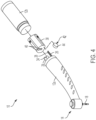
Fig. 4 is a top left perspective partial exploded view of the dental handpiece ofFig. 1 . - Certain terminology is used in the following description for convenience only and is not limiting. The words "right", "left", "lower", and "upper" designate directions in the drawings to which reference is made. The words "inwardly" and "outwardly" refer to directions toward and away from, respectively, the geometric center of the device and designated parts thereof. The terminology includes the above-listed words, derivatives thereof, and words of similar import. Additionally, the words "a" and "an", as used in the claims and in the corresponding portions of the specification, mean "at least one."
- It should also be understood that the terms "about," "approximately," "generally," "substantially" and like terms, used herein when referring to a dimension or characteristic of a component, indicate that the described dimension/characteristic is not a strict boundary or parameter and does not exclude minor variations therefrom that are functionally similar. At a minimum, such references that include a numerical parameter would include variations that, using mathematical and industrial principles accepted in the art (e.g., rounding, measurement or other systematic errors, manufacturing tolerances, etc.), would not vary the least significant digit.
- Referring to
Figs. 1-4 , there is shown a first preferred embodiment of adental handpiece 10, which preferably includes ahandle portion 12 and ahead portion 14. Thehead portion 14 preferably supports a high-speed, air-driventurbine 16 to which adental tool 18, such as a burr, drill bit, or the like, may be attached for rotation therewith. Thedental tool 18 may be removable from theturbine 16 andhead portion 14 for maintenance, replacement, or the like. At an end opposite thehead portion 14, thehandle portion 12 is preferably connected to a supply hose (not shown), which provides compressed air or a similar fluid for driving theturbine 16. - The
handle portion 12 preferably is formed from afore housing 12a with thehead portion 14 located at a fore end thereof, and an opposite aft end removably connected to anaft housing 12b. Thehead portion 14 may be integrally formed with thefore housing 12a, or may be a separate component attached to the fore end of thefore housing 12a via threading, welding, or other like connecting methods. The aft end of thefore housing 12a preferably includes athread 20 for coupling to acomplementary thread 22 on theaft housing 12b. Both the fore andaft housings aft housings - The
fore housing 12a preferably includes adrive fluid tube 24 that extends from the aft end of thefore housing 12a to thehead portion 14 for introducing the drive fluid (e.g., compressed air) to theturbine 16. Thefore housing 12a further includes a coolingair tube 26 and a cooling fluid tube 28 that extend from the aft end of thefore housing 12a. The cooling air and coolingfluid tubes 26, 28 preferably transport air and fluid (e.g., water) provided by the supply hose. The cooling air and coolingfluid tubes 26, 28 may merge into a coolingmist tube 30, which is shown in the drawings within thefore housing 12a. There, the air and fluid combine to form a mist, which is transported by the coolingmist tube 30 to thehead portion 14, where the mist is emitted from one or more ports 32 toward thedental tool 18. The mist allows for cooling and/or cleaning of thedental tool 18 and/or the work site in the patient's mouth. In alternative embodiments, the cooling air and cooling fluid may be mixed prior to reaching thedental handpiece 10, such that only the coolingmist tube 30 is required. In other embodiments, only the coolingair tube 26 or the cooling fluid tube 28 may be required. - The
fore housing 12a further preferably includes a fiber-optic cable 34 extending from the aft end of thefore housing 12a toward thehead portion 14, terminating in alight opening 36 in thehead portion 14. The fiber-optic cable 34 preferably directs light provided by the supply hose toward thedental tool 18 and work site through thelight opening 36. In alternative embodiments, the fiber-optic cable 34 may optically couple to a lamp (not shown), such as an LED, that is mounted within the fore oraft housing dental handpiece 10. In still other embodiments, the fiber-optic cable 34 may be omitted altogether and there may be a lamp (e.g., and LED) mounted at or near thehead portion 14 that receives power from the supply hose and a power cable (not shown) running through the fore andaft housings - A manifold 38 is preferably disposed within the
aft housing 12b to couple the drive fluid, cooling air, and coolingfluid tubes optic cable 34 to corresponding supply lines (not shown) from the supply hose. The manifold 38 preferably is formed as a solid body with a plurality of connection openings 40 formed therethrough for receiving respective ones of the drive fluid, cooling air, and coolingfluid tubes optic cable 34 at a fore end thereof, as well as respective supply lines from the supply hose at an aft end thereof. The drive fluid, cooling air, and coolingfluid tubes optic cable 34 preferably couple to the respective connection openings via an interference fit, although other types of like connections can be made as well. In the embodiment shown inFigs. 1-4 , the drive fluid, cooling air, and coolingfluid tubes optic cable 34 preferably extend beyond the aft end of thefore housing 12a for ease of connection with the manifold 38, but the manifold 38 could just as easily extend into thefore housing 12a to make the appropriate connections. By connecting to the various tubes and cables from thefore housing 12a, the manifold 38 is preferably kept from rotating with theaft housing 12b, allowing theaft housing 12b to be screwed onto thefore housing 12a without disrupting the necessary fluid and cable connections. - The
aft housing 12b preferably defines a longitudinally extending handle axis H. For ease of use within the patient's mouth, thefore housing 12a may include a bend such that a portion of thefore housing 12a preferably extends at an angle transverse to the handle axis H, placing thehead portion 14, and thedental tool 18 off-center with respect to the handle axis H. However, in some embodiments, the bend may occur in theaft housing 12b. - The
aft housing 12b preferably contains awireless communication device 42, preferably in the form of a radio frequency identification (RFID) chip, containing at least an antenna and a memory (not shown). The memory preferably stores information related to use and/or maintenance of thedental handpiece 10, for example, dates, times, and/or durations of use, cleaning, lubricating, autoclaving, and the like. In simpler embodiments, the memory may simply store a binary indicator regarding whether thedental handpiece 10 has been used, cleaned, lubricated, autoclaved, and/or the like. Additional information may also be stored, such as a unique identifier of thedental handpiece 10, a manufacturing date, the number of times of use, cleaning, or the like, whether thedental tool 18 has been replaced, and other like information useful to the operator for tracking or determining a condition of thedental handpiece 10. It is preferred that the data be encrypted to prevent illicit reading or writing functions in connection with thewireless communication device 42. - The stored data may be written to the
wireless communication device 42 by one or more external writers. For example, an external writer may be present at various dedicated locations, e.g., an external writer may be associated with an autoclave, another external writer may reside near a dental chair to register use, another external writer may be located near a lubrication station, and the like. Alternatively, for example, a single external writer may be used to write all data to thewireless communication device 42. Similarly, reading and writing functions may be combined within a single external device or spread out among different external devices at various locations. - While the
wireless communication device 42 in the preferred embodiment is an RFID chip, other types of wireless communication devices can be used as well, such as near-field communication (NFC) chips, a BLUETOOTH low energy (BLE) chip, or the like. Moreover, it is preferred that thewireless communication device 42 be powered solely by an interrogation or other signal from an external reader and/or writer (not shown), although a separate local power supply (not shown) can be provided within thedental handpiece 10 for thewireless communication device 42, or power can be provided externally from the supply hose. - It is further preferred that the
wireless communication device 42 be electrically isolated from other components in thedental handpiece 10. That is, thewireless communication device 42 preferably has no physical connection or contact with any other electrical, electronic, or energy-emitting component or device of thedental handpiece 10. Thewireless communication device 42 is further shown inFigs. 1-4 to be encapsulated in asubstrate material 44 that may be made from silicone, a polymeric material, a silicone-polymer composite, or a like electrically inert material that allows wireless signals to pass substantially unimpeded from and to thewireless communication device 42. - The
substrate material 44 may also serve as a bonding agent to secure thewireless communication device 42 to another component of thedental handpiece 10. InFigs. 1 and2 , thewireless communication device 42 is shown attached to the fiber-optic cable 34 within theaft housing 12b. In alternative embodiments, thewireless communication device 42 may be attached to one or more other components, such as thedrive fluid tube 24, the cooling air or coolingfluid tubes 26, 28, the coolingmist tube 30, the manifold 38, or the like. However, it is preferred that the one or more components to which thewireless communication device 42 is attached be of a construction so as to provide constructive interference to signals being sent and/or received by thewireless communication device 42. For example, the fiber-optic cable 34 or one of thetubes optic cable 34 may enable an improved wireless signal accessible by the external reader or writer since the signals transmitted by thewireless communication device 42 are not emanated in multiple different directions, but are better focused. In still other embodiments, thewireless communication device 42 can be attached to an interior wall of theaft housing 12b or thefore housing 12a. - Conventional dental handpieces are primarily made from a metal material (e.g., stainless steel or the like), which is not conducive to the transmission of wireless signals. To accommodate the
wireless communication device 42, theaft housing 12b, or at least portions thereof surrounding thewireless communication device 42, are preferably made from a dielectric material, for example polyether ether ketone (PEEK) or the like, which allows for transmission and/or emissions of wireless signal energy. Thefore housing 12a may nonetheless continue to be made from a more conventional material, unless thewireless communication device 42 is housed or partially housed therein, in which case at least a portion of thefore housing 12a should be made from a dielectric material. - With the
wireless communication device 42 embedded within thedental handpiece 10 and within thesubstrate material 44, it is suitably protected during use, cleaning, autoclaving, and like processes performed on thedental handpiece 10. The threaded connection of the fore andaft housings wireless communication device 42 for removal and/or replacement, as necessary. - It is further preferred that the
wireless communication device 42 be mounted such that a central, longitudinal axis A (Fig. 3 ) thereof is oriented substantially perpendicularly with respect to handle axis H. Such an orientation may enhance the wireless signal propagation in convenient directions, thereby making reading and writing operations easier. - While the
dental handpiece 10 shown and described herein is shown to be a pneumatic handpiece, other types of handpieces, as are conventionally known, may also be used within the scope of the present invention as defined by the appended claims. - While specific and distinct embodiments have been shown in the drawings, various individual elements or combinations of elements from the different embodiments may be combined with one another within the scope of the appended claims. Thus, an individual feature described herein only with respect to one embodiment should not be construed as being incompatible with other embodiments described herein or otherwise encompassed by the invention.
- It will be appreciated by those skilled in the art that changes could be made to the embodiments described above without departing from the scope of the present invention as defined by the appended claims.
Claims (17)
- A dental handpiece (10) comprising:a head portion (14) supporting a turbine (16) configured for receiving a removable dental tool (18) for rotation therewith;a handle portion (12) having a first end, an opposing second end, and an internal cavity, the head portion (14) being disposed at the first end of the handle portion (12) and the second end of the handle portion (12) being configured for removable connection to a supply hose;one or more conduits (24, 26, 28) extending at least partially through the internal cavity of the handle portion (12) toward the head portion (14), at least one of the one or more conduits being a drive fluid tube (24) configured to deliver a drive fluid to the head portion (14) for rotating the turbine (16);a wireless communication device (42) disposed within the internal cavity of the handle portion (12) and attached to at least one of the one or more conduits (24), at least a section of the handle portion (12) surrounding the wireless communication device (42) being formed of a dielectric material, the wireless communication device (42) being configured to wirelessly communicate with a reader or writer external to the dental handpiece and configured to store data related to at least one of identification, use, or maintenance of the dental handpiece; andan electrically inert substrate material (44) encapsulating the wireless communication device (42), the wireless communication device (42) being electrically isolated from other components of the dental handpiece (10).
- The dental handpiece (10) of claim 1, wherein the handle portion (12) is formed from a first housing (12a) encompassing the first end and a second housing (12b) encompassing the second end, the first and second housings (12a, 12b) together defining the internal cavity.
- The dental handpiece (10) of claim 2, wherein the second housing (12b) contains the wireless communication device (42).
- The dental handpiece (10) of claim 3, wherein the second housing (12b) is formed of the dielectric material.
- The dental handpiece (10) of claim 4, wherein:the second housing (12b) defines a longitudinally extending handle axis (H);the first housing (12a) includes a bend such that a portion of the first housing extends at an angle transverse to the handle axis (H);a manifold (38) is disposed within the internal cavity and contained in the second housing (12b), the manifold (38) including a plurality of connection openings (40) and being configured for receiving the supply hose;a the drive tube (24) is a compressed air tube connected to one of the connection openings of the manifold (38) and the drive fluid is compressed air;the one or more conduits (24, 26, 28) include a fiber-optic cable (34) connected to another of the connection openings (40) of the manifold (38) and extending through the internal cavity and terminating at a light opening (36) in the head portion (14), the fiber-optic cable being made at least partially from metal, and;the wireless communication device (42) is an RFID chip attached to the fiber-optic cable (34) within the internal cavity, the RFID chip having a central, longitudinal axis (A) that is oriented substantially perpendicularly with respect to the handle axis (H).
- The dental handpiece (10) of claim 2, wherein the second housing (12b) attaches to the first housing (12a) using a threaded connection (20, 22).
- The dental handpiece (10) of claim 1, wherein the handle portion (12) extends from the second end in an initial direction that defines a handle axis (H).
- The dental handpiece (10) of claim 7, wherein the wireless communication device (42) has a central, longitudinal axis (A) that is oriented substantially perpendicularly with respect to the handle axis (H).
- The dental handpiece (10) of claim 1, wherein the one or more conduits (24, 26, 28) includes a fiber-optic cable (34).
- The dental handpiece (10) of claim 7, wherein the wireless communication device (42) is attached to the fiber-optic cable (34).
- The dental handpiece (10) of claim 1, wherein the at least one of the one or more conduits (24, 26, 28) to which the wireless communication device (42) is attached is made from metal.
- The dental handpiece (10) of claim 1, wherein the substrate material (44) is made from one of silicone, a polymeric material, or a silicone-polymer composite.
- The dental handpiece (10) of claim 1, wherein the dielectric material is polyether ether ketone.
- The dental handpiece (10) of claim 1, wherein the wireless communication device (42) is configured to be powered by a signal from the external reader or writer.
- The dental handpiece (10) of claim 1, wherein the wireless communication device (42) is an RFID chip.
- The dental handpiece (10) of claim 1, wherein the data includes at least one of dates, times, or durations of at least one of use, cleaning, lubricating, or autoclaving of the dental handpiece (10).
- The dental handpiece (10) of claim 1, wherein the data includes a unique identifier of the dental handpiece (10).
Applications Claiming Priority (2)
| Application Number | Priority Date | Filing Date | Title |
|---|---|---|---|
| US201962907981P | 2019-09-30 | 2019-09-30 | |
| PCT/US2020/048753 WO2021066978A1 (en) | 2019-09-30 | 2020-08-31 | Dental handpiece with embedded wireless communication device |
Publications (4)
| Publication Number | Publication Date |
|---|---|
| EP4037601A1 EP4037601A1 (en) | 2022-08-10 |
| EP4037601A4 EP4037601A4 (en) | 2023-10-04 |
| EP4037601B1 true EP4037601B1 (en) | 2025-02-26 |
| EP4037601C0 EP4037601C0 (en) | 2025-02-26 |
Family
ID=75338517
Family Applications (1)
| Application Number | Title | Priority Date | Filing Date |
|---|---|---|---|
| EP20871726.4A Active EP4037601B1 (en) | 2019-09-30 | 2020-08-31 | Dental handpiece with embedded wireless communication device |
Country Status (4)
| Country | Link |
|---|---|
| US (1) | US12533209B2 (en) |
| EP (1) | EP4037601B1 (en) |
| JP (2) | JP7460764B2 (en) |
| WO (1) | WO2021066978A1 (en) |
Families Citing this family (1)
| Publication number | Priority date | Publication date | Assignee | Title |
|---|---|---|---|---|
| US12539201B2 (en) * | 2020-04-27 | 2026-02-03 | Innovative Bioceramix Inc. | Endodontic handpiece systems and methods |
Family Cites Families (57)
| Publication number | Priority date | Publication date | Assignee | Title |
|---|---|---|---|---|
| JP3897962B2 (en) | 2000-07-19 | 2007-03-28 | 株式会社モリタ製作所 | Identification-type instrument body, identification-type adapter, identification-type tube, and medical device using these |
| US7092605B2 (en) | 2003-01-30 | 2006-08-15 | Commscope Properties, Llc | Fiber optic cable with composite polymeric/metallic armor |
| FR2864442B1 (en) * | 2003-11-25 | 2006-08-04 | Micro Mega Int Mfg Sa | DENTAL HANDPIECE WITH A SINGLE PIECE BODY COMPRISING AN ELECTRICAL AND ELASTIC BONDING MEMBER BETWEEN THE MECHANICAL TRANSMISSION BODIES AND THE HEAD OF THE INSTRUMENT |
| JP3920281B2 (en) | 2004-06-07 | 2007-05-30 | 株式会社ナカニシ | Dental handpiece and manufacturing method thereof |
| US20060142744A1 (en) | 2004-07-27 | 2006-06-29 | Dmitri Boutoussov | Identification connector for a medical laser handpiece |
| US7473097B2 (en) | 2004-12-17 | 2009-01-06 | 3M Innovative Properties Company | RFID tracking of patient-specific orthodontic materials |
| FR2881341B1 (en) | 2005-02-02 | 2007-05-11 | Satelec Sa | DENTAL TREATMENT APPARATUS WITH AUTOMATIC INSERT RECOGNITION |
| US20060234185A1 (en) | 2005-02-17 | 2006-10-19 | Discus Dental Impressions Inc. | Ultrasonic dental tool having a light source |
| JP2006269086A (en) | 2005-03-22 | 2006-10-05 | Matsushita Electric Ind Co Ltd | Lead acid battery |
| US7837694B2 (en) | 2005-04-28 | 2010-11-23 | Warsaw Orthopedic, Inc. | Method and apparatus for surgical instrument identification |
| FR2891132B1 (en) | 2005-09-29 | 2007-11-30 | Fkg Dentaire Sa | METHOD AND DEVICE FOR IDENTIFYING AND CONTROLLING A MEDICAL INSTRUMENT |
| US7630791B2 (en) | 2005-12-09 | 2009-12-08 | CareFusion 303 Inc. | System and method for storing items and tracking item usage |
| US8303304B2 (en) | 2006-12-18 | 2012-11-06 | Dentsply International, Inc. | Closed loop speed control for a pneumatic dental handpiece |
| EP2077519B1 (en) | 2006-02-22 | 2014-04-02 | Toyo Seikan Kaisha, Ltd. | RFID tag substrate for metal component |
| US20080014550A1 (en) | 2006-07-13 | 2008-01-17 | Henry Schein, Inc. | Dental handpiece performance sensor |
| JP5009576B2 (en) | 2006-09-19 | 2012-08-22 | 新光電気工業株式会社 | Manufacturing method of semiconductor device |
| JP2008113632A (en) * | 2006-11-07 | 2008-05-22 | Hitachi Ltd | RFID tag for living body implantation and its insertion |
| US8204612B2 (en) | 2006-11-16 | 2012-06-19 | James Feine | Tip-based computer controlled system for a hand-held dental delivery device |
| JP2008210032A (en) | 2007-02-23 | 2008-09-11 | Fujitsu Ltd | RFID tag |
| US20090148810A1 (en) | 2007-02-21 | 2009-06-11 | Randall Maxwell | Wireless root canal apex locator |
| US20090047624A1 (en) | 2007-08-13 | 2009-02-19 | Chih-I Tsai | Ultrasonic scaler |
| CA2722328A1 (en) | 2008-04-24 | 2009-10-29 | Pourya Dehnadi | Payload aware medical cart, system and method |
| US8235716B2 (en) | 2008-06-24 | 2012-08-07 | Marc Lemchen | Method for using radio frequency identification microchips in orthodontic brackets |
| EP2201907B1 (en) | 2008-12-24 | 2013-12-18 | W & H Dentalwerk Bürmoos GmbH | Method and apparatus for programming a cordless handpiece serving the preparation of a root canal |
| EP2233103B1 (en) * | 2009-03-26 | 2017-11-15 | W & H Dentalwerk Bürmoos GmbH | Medical, in particular dental handpiece |
| US10098708B2 (en) | 2009-04-30 | 2018-10-16 | Inter-Med, Inc. | Ultrasonic device having memory capabilities |
| US20110039229A1 (en) * | 2009-08-11 | 2011-02-17 | Discus Dental, Llc | Computer aided canal instrumentation system and a unique endodontic instrument design |
| WO2011118379A1 (en) | 2010-03-24 | 2011-09-29 | 株式会社村田製作所 | Rfid system |
| US9789295B2 (en) * | 2010-11-02 | 2017-10-17 | Yuchen Zhou | Customized skin care and method to provide same |
| WO2012156496A2 (en) | 2011-05-19 | 2012-11-22 | W & H Dentalwerk Bürmoos GmbH | Medical instrument, in particular dental instrument, with a temperature measurement device |
| EP2581061B1 (en) | 2011-10-10 | 2017-04-19 | W & H Dentalwerk Bürmoos GmbH | Coupling device for a releasable connection of a medical, in particular dental instrument with a drive unit or a supply hose |
| US10011050B2 (en) | 2011-10-12 | 2018-07-03 | Ormco Corporation | Fabrication of an orthodontic aligner from a negative mold designed by a computational device |
| US20160345917A1 (en) | 2011-10-28 | 2016-12-01 | Navigate Surgical Technologies, Inc. | Method for making a three-dimensionally trackable apparatus |
| US9204804B2 (en) | 2012-03-09 | 2015-12-08 | 3Shape A/S | 3D scanner with steam autoclavable tip containing a heated optical element |
| US20150084745A1 (en) | 2012-05-23 | 2015-03-26 | Allen D. Hertz | Misplaced Article Recovery Process |
| US9820827B2 (en) | 2012-06-13 | 2017-11-21 | James Feine | Ablation method and device |
| US20150150647A1 (en) | 2012-07-03 | 2015-06-04 | NOVENDO Sarl | Dental tool comprising a versatile tip |
| CA2886005C (en) | 2012-09-24 | 2017-04-11 | Satyatek Sa | Radio frequency identification capsule (rfid) |
| US9636195B2 (en) | 2012-09-28 | 2017-05-02 | Stephen H. Wolpo | Hands free oral hygiene system |
| US8937544B2 (en) | 2012-11-05 | 2015-01-20 | DePuy Synthes Products, LLC | Systems and methods for tagging and tracking surgical devices and surgical accessories using radio frequency identification tags |
| CA3132712A1 (en) | 2013-02-04 | 2014-08-07 | Sonendo, Inc. | Dental treatment system |
| WO2014123904A2 (en) | 2013-02-05 | 2014-08-14 | Convergent Dental, Inc. | Dental laser apparatus and method of use with interchangeable hand piece and variable foot pedal |
| FI127821B (en) | 2013-05-17 | 2019-03-15 | Lm Instr Oy | A medical or a dental instrument and a method for manufacturing the same |
| CA2977547A1 (en) | 2015-02-23 | 2016-09-01 | Universal Implant Technologies Pty Limited | Dental implant identification system |
| DE102015111757A1 (en) | 2015-03-09 | 2016-09-15 | Sycotec Gmbh & Co. Kg | Dental or surgical handpiece |
| EP3120803A1 (en) | 2015-07-24 | 2017-01-25 | Nobel Biocare Services AG | Retention element for attaching a first dental component to a second dental component and dental assembly comprising the retention element |
| JP6643182B2 (en) * | 2016-05-18 | 2020-02-12 | 株式会社吉田製作所 | Treatment instrument temperature information management device |
| US11529213B2 (en) * | 2016-05-30 | 2022-12-20 | David Akselrod | Backscatter device-based dental imaging apparatus |
| US20180092712A1 (en) | 2016-09-30 | 2018-04-05 | Kerr Corporation | Tool recognition system with impedance sensing for dental devices |
| EP3551034A1 (en) * | 2016-12-07 | 2019-10-16 | Progenity, Inc. | Gastrointestinal tract detection methods, devices and systems |
| JP6333935B2 (en) | 2016-12-15 | 2018-05-30 | 株式会社モリタ製作所 | Medical medical device and medical treatment tool |
| US20180256287A1 (en) | 2017-03-13 | 2018-09-13 | Kerr Corporation | Tool rfid recognition system for dental devices |
| US10881490B2 (en) | 2017-06-08 | 2021-01-05 | Kavo Dental Technologies, Llc | Handpiece maintenance system and dental instruments for predictive maintenance |
| US20190069980A1 (en) | 2017-09-07 | 2019-03-07 | Ormco Corporation | Orthodontic storage and dispensing systems, packages, and methods of making and using same |
| JP6746245B2 (en) * | 2018-01-24 | 2020-08-26 | 株式会社吉田製作所 | Dental handpiece management system |
| EP3784163B1 (en) * | 2018-04-25 | 2022-12-07 | DENTSPLY SIRONA Inc. | Dental tool, dental handpiece and dental system |
| JP6453514B2 (en) * | 2018-07-13 | 2019-01-16 | 株式会社モリタ製作所 | Dental medical device and dental treatment tool |
-
2020
- 2020-08-31 EP EP20871726.4A patent/EP4037601B1/en active Active
- 2020-08-31 JP JP2022519993A patent/JP7460764B2/en active Active
- 2020-08-31 WO PCT/US2020/048753 patent/WO2021066978A1/en not_active Ceased
- 2020-08-31 US US17/764,783 patent/US12533209B2/en active Active
-
2023
- 2023-12-07 JP JP2023206978A patent/JP7743486B2/en active Active
Also Published As
| Publication number | Publication date |
|---|---|
| JP2022550184A (en) | 2022-11-30 |
| EP4037601C0 (en) | 2025-02-26 |
| EP4037601A1 (en) | 2022-08-10 |
| US12533209B2 (en) | 2026-01-27 |
| JP7743486B2 (en) | 2025-09-24 |
| EP4037601A4 (en) | 2023-10-04 |
| JP7460764B2 (en) | 2024-04-02 |
| JP2024028908A (en) | 2024-03-05 |
| WO2021066978A1 (en) | 2021-04-08 |
| US20220354616A1 (en) | 2022-11-10 |
Similar Documents
| Publication | Publication Date | Title |
|---|---|---|
| US9730765B2 (en) | Medical or dental handpiece with inductive coupling | |
| JP5872053B2 (en) | Connecting means for detachable connection of a medical, in particular dental instrument, to a drive unit or supply hose | |
| US10485405B2 (en) | Coupling device for releasable connection of a medical or dental handpiece to a drive unit or to a supply tubing | |
| ES2345191T3 (en) | SMART FIBER FOR THERAPY. | |
| US7887559B2 (en) | Surgical cutting accessory with encapsulated RFID chip | |
| US20040122419A1 (en) | Medical device recognition system with write-back feature | |
| WO2018169565A1 (en) | Tool rfid recognition system for dental devices | |
| US12533209B2 (en) | Dental handpiece with embedded wireless communication device | |
| US11576692B2 (en) | System for crushing and/or removing body stones, method for providing such a system and adapter element | |
| CA2977547A1 (en) | Dental implant identification system | |
| CN112543621A (en) | System and method for connecting instruments | |
| US20080221564A1 (en) | Method and Device for Identifying and Monitoring a Medical Instrument | |
| EP3866706A2 (en) | Tool having a working end determining device in the shaft region | |
| RU2742238C2 (en) | Core bit crown | |
| CN112739286A (en) | Dental or surgical handpiece with RFID transponder | |
| CN111727019A (en) | Dental handpiece, dental handpiece management system, and manufacturing method of dental handpiece | |
| CN109715326B (en) | Coring bit |
Legal Events
| Date | Code | Title | Description |
|---|---|---|---|
| STAA | Information on the status of an ep patent application or granted ep patent |
Free format text: STATUS: THE INTERNATIONAL PUBLICATION HAS BEEN MADE |
|
| PUAI | Public reference made under article 153(3) epc to a published international application that has entered the european phase |
Free format text: ORIGINAL CODE: 0009012 |
|
| STAA | Information on the status of an ep patent application or granted ep patent |
Free format text: STATUS: REQUEST FOR EXAMINATION WAS MADE |
|
| 17P | Request for examination filed |
Effective date: 20220331 |
|
| AK | Designated contracting states |
Kind code of ref document: A1 Designated state(s): AL AT BE BG CH CY CZ DE DK EE ES FI FR GB GR HR HU IE IS IT LI LT LU LV MC MK MT NL NO PL PT RO RS SE SI SK SM TR |
|
| DAV | Request for validation of the european patent (deleted) | ||
| DAX | Request for extension of the european patent (deleted) | ||
| A4 | Supplementary search report drawn up and despatched |
Effective date: 20230905 |
|
| RIC1 | Information provided on ipc code assigned before grant |
Ipc: A61C 1/05 20060101ALI20230831BHEP Ipc: A61B 90/96 20160101ALI20230831BHEP Ipc: A61B 90/90 20160101ALI20230831BHEP Ipc: A61B 34/30 20160101ALI20230831BHEP Ipc: A61B 34/20 20160101ALI20230831BHEP Ipc: A61B 90/98 20160101AFI20230831BHEP |
|
| GRAP | Despatch of communication of intention to grant a patent |
Free format text: ORIGINAL CODE: EPIDOSNIGR1 |
|
| STAA | Information on the status of an ep patent application or granted ep patent |
Free format text: STATUS: GRANT OF PATENT IS INTENDED |
|
| INTG | Intention to grant announced |
Effective date: 20240925 |
|
| GRAS | Grant fee paid |
Free format text: ORIGINAL CODE: EPIDOSNIGR3 |
|
| GRAA | (expected) grant |
Free format text: ORIGINAL CODE: 0009210 |
|
| STAA | Information on the status of an ep patent application or granted ep patent |
Free format text: STATUS: THE PATENT HAS BEEN GRANTED |
|
| AK | Designated contracting states |
Kind code of ref document: B1 Designated state(s): AL AT BE BG CH CY CZ DE DK EE ES FI FR GB GR HR HU IE IS IT LI LT LU LV MC MK MT NL NO PL PT RO RS SE SI SK SM TR |
|
| REG | Reference to a national code |
Ref country code: GB Ref legal event code: FG4D |
|
| REG | Reference to a national code |
Ref country code: CH Ref legal event code: EP |
|
| REG | Reference to a national code |
Ref country code: DE Ref legal event code: R096 Ref document number: 602020046959 Country of ref document: DE |
|
| REG | Reference to a national code |
Ref country code: IE Ref legal event code: FG4D |
|
| U01 | Request for unitary effect filed |
Effective date: 20250324 |
|
| U07 | Unitary effect registered |
Designated state(s): AT BE BG DE DK EE FI FR IT LT LU LV MT NL PT RO SE SI Effective date: 20250328 |
|
| PG25 | Lapsed in a contracting state [announced via postgrant information from national office to epo] |
Ref country code: RS Free format text: LAPSE BECAUSE OF FAILURE TO SUBMIT A TRANSLATION OF THE DESCRIPTION OR TO PAY THE FEE WITHIN THE PRESCRIBED TIME-LIMIT Effective date: 20250526 |
|
| PG25 | Lapsed in a contracting state [announced via postgrant information from national office to epo] |
Ref country code: PL Free format text: LAPSE BECAUSE OF FAILURE TO SUBMIT A TRANSLATION OF THE DESCRIPTION OR TO PAY THE FEE WITHIN THE PRESCRIBED TIME-LIMIT Effective date: 20250226 |
|
| PG25 | Lapsed in a contracting state [announced via postgrant information from national office to epo] |
Ref country code: ES Free format text: LAPSE BECAUSE OF FAILURE TO SUBMIT A TRANSLATION OF THE DESCRIPTION OR TO PAY THE FEE WITHIN THE PRESCRIBED TIME-LIMIT Effective date: 20250226 |
|
| PG25 | Lapsed in a contracting state [announced via postgrant information from national office to epo] |
Ref country code: NO Free format text: LAPSE BECAUSE OF FAILURE TO SUBMIT A TRANSLATION OF THE DESCRIPTION OR TO PAY THE FEE WITHIN THE PRESCRIBED TIME-LIMIT Effective date: 20250526 Ref country code: IS Free format text: LAPSE BECAUSE OF FAILURE TO SUBMIT A TRANSLATION OF THE DESCRIPTION OR TO PAY THE FEE WITHIN THE PRESCRIBED TIME-LIMIT Effective date: 20250626 |
|
| PG25 | Lapsed in a contracting state [announced via postgrant information from national office to epo] |
Ref country code: HR Free format text: LAPSE BECAUSE OF FAILURE TO SUBMIT A TRANSLATION OF THE DESCRIPTION OR TO PAY THE FEE WITHIN THE PRESCRIBED TIME-LIMIT Effective date: 20250226 |
|
| PG25 | Lapsed in a contracting state [announced via postgrant information from national office to epo] |
Ref country code: GR Free format text: LAPSE BECAUSE OF FAILURE TO SUBMIT A TRANSLATION OF THE DESCRIPTION OR TO PAY THE FEE WITHIN THE PRESCRIBED TIME-LIMIT Effective date: 20250527 |
|
| U20 | Renewal fee for the european patent with unitary effect paid |
Year of fee payment: 6 Effective date: 20250827 |
|
| PG25 | Lapsed in a contracting state [announced via postgrant information from national office to epo] |
Ref country code: SM Free format text: LAPSE BECAUSE OF FAILURE TO SUBMIT A TRANSLATION OF THE DESCRIPTION OR TO PAY THE FEE WITHIN THE PRESCRIBED TIME-LIMIT Effective date: 20250226 |
|
| PG25 | Lapsed in a contracting state [announced via postgrant information from national office to epo] |
Ref country code: CZ Free format text: LAPSE BECAUSE OF FAILURE TO SUBMIT A TRANSLATION OF THE DESCRIPTION OR TO PAY THE FEE WITHIN THE PRESCRIBED TIME-LIMIT Effective date: 20250226 |
|
| PG25 | Lapsed in a contracting state [announced via postgrant information from national office to epo] |
Ref country code: SK Free format text: LAPSE BECAUSE OF FAILURE TO SUBMIT A TRANSLATION OF THE DESCRIPTION OR TO PAY THE FEE WITHIN THE PRESCRIBED TIME-LIMIT Effective date: 20250226 |
|
| PLBE | No opposition filed within time limit |
Free format text: ORIGINAL CODE: 0009261 |
|
| STAA | Information on the status of an ep patent application or granted ep patent |
Free format text: STATUS: NO OPPOSITION FILED WITHIN TIME LIMIT |
|
| REG | Reference to a national code |
Ref country code: CH Ref legal event code: L10 Free format text: ST27 STATUS EVENT CODE: U-0-0-L10-L00 (AS PROVIDED BY THE NATIONAL OFFICE) Effective date: 20260107 |
|
| 26N | No opposition filed |
Effective date: 20251127 |
|
| REG | Reference to a national code |
Ref country code: CH Ref legal event code: H13 Free format text: ST27 STATUS EVENT CODE: U-0-0-H10-H13 (AS PROVIDED BY THE NATIONAL OFFICE) Effective date: 20260324 |
|
| PG25 | Lapsed in a contracting state [announced via postgrant information from national office to epo] |
Ref country code: MC Free format text: LAPSE BECAUSE OF FAILURE TO SUBMIT A TRANSLATION OF THE DESCRIPTION OR TO PAY THE FEE WITHIN THE PRESCRIBED TIME-LIMIT Effective date: 20250226 |
|
| PG25 | Lapsed in a contracting state [announced via postgrant information from national office to epo] |
Ref country code: CH Free format text: LAPSE BECAUSE OF NON-PAYMENT OF DUE FEES Effective date: 20250831 |
|
| GBPC | Gb: european patent ceased through non-payment of renewal fee |
Effective date: 20250831 |