EP4037334A1 - Electronic device with display panel - Google Patents
Electronic device with display panel Download PDFInfo
- Publication number
- EP4037334A1 EP4037334A1 EP21182898.3A EP21182898A EP4037334A1 EP 4037334 A1 EP4037334 A1 EP 4037334A1 EP 21182898 A EP21182898 A EP 21182898A EP 4037334 A1 EP4037334 A1 EP 4037334A1
- Authority
- EP
- European Patent Office
- Prior art keywords
- layer
- electronic device
- generating unit
- piezoelectric
- flexible display
- Prior art date
- Legal status (The legal status is an assumption and is not a legal conclusion. Google has not performed a legal analysis and makes no representation as to the accuracy of the status listed.)
- Granted
Links
Images

Classifications
-
- H—ELECTRICITY
- H04—ELECTRIC COMMUNICATION TECHNIQUE
- H04M—TELEPHONIC COMMUNICATION
- H04M1/00—Substation equipment, e.g. for use by subscribers
- H04M1/02—Constructional features of telephone sets
- H04M1/0202—Portable telephone sets, e.g. cordless phones, mobile phones or bar type handsets
- H04M1/026—Details of the structure or mounting of specific components
- H04M1/0266—Details of the structure or mounting of specific components for a display module assembly
-
- H—ELECTRICITY
- H04—ELECTRIC COMMUNICATION TECHNIQUE
- H04R—LOUDSPEAKERS, MICROPHONES, GRAMOPHONE PICK-UPS OR LIKE ACOUSTIC ELECTROMECHANICAL TRANSDUCERS; ELECTRIC HEARING AIDS; PUBLIC ADDRESS SYSTEMS
- H04R17/00—Piezoelectric transducers; Electrostrictive transducers
-
- G—PHYSICS
- G06—COMPUTING OR CALCULATING; COUNTING
- G06F—ELECTRIC DIGITAL DATA PROCESSING
- G06F1/00—Details not covered by groups G06F3/00 - G06F13/00 and G06F21/00
- G06F1/16—Constructional details or arrangements
- G06F1/1613—Constructional details or arrangements for portable computers
- G06F1/1633—Constructional details or arrangements of portable computers not specific to the type of enclosures covered by groups G06F1/1615 - G06F1/1626
- G06F1/1684—Constructional details or arrangements related to integrated I/O peripherals not covered by groups G06F1/1635 - G06F1/1675
- G06F1/1688—Constructional details or arrangements related to integrated I/O peripherals not covered by groups G06F1/1635 - G06F1/1675 the I/O peripheral being integrated loudspeakers
-
- G—PHYSICS
- G09—EDUCATION; CRYPTOGRAPHY; DISPLAY; ADVERTISING; SEALS
- G09F—DISPLAYING; ADVERTISING; SIGNS; LABELS OR NAME-PLATES; SEALS
- G09F9/00—Indicating arrangements for variable information in which the information is built-up on a support by selection or combination of individual elements
- G09F9/30—Indicating arrangements for variable information in which the information is built-up on a support by selection or combination of individual elements in which the desired character or characters are formed by combining individual elements
- G09F9/301—Indicating arrangements for variable information in which the information is built-up on a support by selection or combination of individual elements in which the desired character or characters are formed by combining individual elements flexible foldable or roll-able electronic displays, e.g. thin LCD, OLED
-
- H—ELECTRICITY
- H04—ELECTRIC COMMUNICATION TECHNIQUE
- H04M—TELEPHONIC COMMUNICATION
- H04M1/00—Substation equipment, e.g. for use by subscribers
- H04M1/02—Constructional features of telephone sets
- H04M1/0202—Portable telephone sets, e.g. cordless phones, mobile phones or bar type handsets
- H04M1/026—Details of the structure or mounting of specific components
-
- H—ELECTRICITY
- H04—ELECTRIC COMMUNICATION TECHNIQUE
- H04M—TELEPHONIC COMMUNICATION
- H04M1/00—Substation equipment, e.g. for use by subscribers
- H04M1/02—Constructional features of telephone sets
- H04M1/0202—Portable telephone sets, e.g. cordless phones, mobile phones or bar type handsets
- H04M1/026—Details of the structure or mounting of specific components
- H04M1/0266—Details of the structure or mounting of specific components for a display module assembly
- H04M1/0268—Details of the structure or mounting of specific components for a display module assembly including a flexible display panel
-
- H—ELECTRICITY
- H04—ELECTRIC COMMUNICATION TECHNIQUE
- H04M—TELEPHONIC COMMUNICATION
- H04M1/00—Substation equipment, e.g. for use by subscribers
- H04M1/02—Constructional features of telephone sets
- H04M1/03—Constructional features of telephone transmitters or receivers, e.g. telephone hand-sets
-
- H—ELECTRICITY
- H04—ELECTRIC COMMUNICATION TECHNIQUE
- H04M—TELEPHONIC COMMUNICATION
- H04M1/00—Substation equipment, e.g. for use by subscribers
- H04M1/02—Constructional features of telephone sets
- H04M1/03—Constructional features of telephone transmitters or receivers, e.g. telephone hand-sets
- H04M1/035—Improving the acoustic characteristics by means of constructional features of the housing, e.g. ribs, walls, resonating chambers or cavities
-
- H—ELECTRICITY
- H04—ELECTRIC COMMUNICATION TECHNIQUE
- H04R—LOUDSPEAKERS, MICROPHONES, GRAMOPHONE PICK-UPS OR LIKE ACOUSTIC ELECTROMECHANICAL TRANSDUCERS; ELECTRIC HEARING AIDS; PUBLIC ADDRESS SYSTEMS
- H04R17/00—Piezoelectric transducers; Electrostrictive transducers
- H04R17/005—Piezoelectric transducers; Electrostrictive transducers using a piezoelectric polymer
-
- H—ELECTRICITY
- H04—ELECTRIC COMMUNICATION TECHNIQUE
- H04R—LOUDSPEAKERS, MICROPHONES, GRAMOPHONE PICK-UPS OR LIKE ACOUSTIC ELECTROMECHANICAL TRANSDUCERS; ELECTRIC HEARING AIDS; PUBLIC ADDRESS SYSTEMS
- H04R7/00—Diaphragms for electromechanical transducers; Cones
- H04R7/02—Diaphragms for electromechanical transducers; Cones characterised by the construction
- H04R7/04—Plane diaphragms
-
- H—ELECTRICITY
- H04—ELECTRIC COMMUNICATION TECHNIQUE
- H04R—LOUDSPEAKERS, MICROPHONES, GRAMOPHONE PICK-UPS OR LIKE ACOUSTIC ELECTROMECHANICAL TRANSDUCERS; ELECTRIC HEARING AIDS; PUBLIC ADDRESS SYSTEMS
- H04R7/00—Diaphragms for electromechanical transducers; Cones
- H04R7/02—Diaphragms for electromechanical transducers; Cones characterised by the construction
- H04R7/04—Plane diaphragms
- H04R7/06—Plane diaphragms comprising a plurality of sections or layers
- H04R7/10—Plane diaphragms comprising a plurality of sections or layers comprising superposed layers in contact
-
- H—ELECTRICITY
- H04—ELECTRIC COMMUNICATION TECHNIQUE
- H04R—LOUDSPEAKERS, MICROPHONES, GRAMOPHONE PICK-UPS OR LIKE ACOUSTIC ELECTROMECHANICAL TRANSDUCERS; ELECTRIC HEARING AIDS; PUBLIC ADDRESS SYSTEMS
- H04R2499/00—Aspects covered by H04R or H04S not otherwise provided for in their subgroups
- H04R2499/10—General applications
- H04R2499/11—Transducers incorporated or for use in hand-held devices, e.g. mobile phones, PDA's, camera's
-
- H—ELECTRICITY
- H04—ELECTRIC COMMUNICATION TECHNIQUE
- H04R—LOUDSPEAKERS, MICROPHONES, GRAMOPHONE PICK-UPS OR LIKE ACOUSTIC ELECTROMECHANICAL TRANSDUCERS; ELECTRIC HEARING AIDS; PUBLIC ADDRESS SYSTEMS
- H04R2499/00—Aspects covered by H04R or H04S not otherwise provided for in their subgroups
- H04R2499/10—General applications
- H04R2499/15—Transducers incorporated in visual displaying devices, e.g. televisions, computer displays, laptops
Definitions
- the present disclosure relates to the technical field of display panels, and more particularly to a display panel for an electronic device.
- the present disclosure provides an electronic device, to solve the shortcomings in the related art.
- an electronic device includes: a display panel assembly; a piezoelectric sound-generating unit bonded to the display panel assembly along a thickness direction of the electronic device; and a structural member connected to the display panel assembly to define a cavity having the piezoelectric sound-generating unit arranged in the cavity; or connected to the piezoelectric sound-generating unit.
- a gap between the structural member and the piezoelectric sound-generating unit.
- the display panel assembly includes: a flexible display layer; and a support layer bonded to the flexible display layer along the thickness direction of the electronic device, the piezoelectric sound-generating unit being connected to the flexible display layer or the support layer.
- the structural member includes a first avoiding groove.
- the support layer is connected to the structural member to seal the first avoiding groove, to form the cavity, and the piezoelectric sound-generating unit is connected to an area, sealing the first avoiding groove, of the support layer.
- the support layer includes an accommodation chamber extending from a side away from the flexible display layer towards the flexible display layer, and the piezoelectric sound-generating unit is arranged in the accommodation chamber and connected to the flexible display layer or the support layer; preferably the structural member is connected to the side of the support layer away from the flexible display layer to seal the accommodation chamber, to form the cavity.
- the support layer includes a bonding layer and a main body layer, and the bonding layer bonds the main body layer with the flexible display layer; the accommodation chamber penetrates the bonding layer and the main body layer, and the piezoelectric sound-generating unit is connected to the flexible display layer.
- the support layer includes a bonding layer and a main body layer, and the bonding layer bonds the main body layer with the flexible display layer; the accommodation chamber penetrates the main body layer; and the piezoelectric sound-generating unit is connected to the bonding layer, in which the bonding layer includes a light-shielding bonding layer.
- the piezoelectric sound-generating unit has a thickness less than a depth of the accommodation chamber, and a side of the structural member towards the support layer is planar.
- the piezoelectric sound-generating unit has a thickness greater than a depth of the accommodation chamber
- the structural member includes a second avoiding groove recessed from a side towards the support layer to a side away from the support layer, in which the second avoiding groove is in communication with the accommodation chamber to form the cavity.
- the structural member includes a middle frame.
- the cavity has a height of greater than 0.08 mm and less than 0.2 mm in a thickness direction of the piezoelectric sound-generating unit; and/or, the piezoelectric sound-generating unit includes a piezoelectric ceramic unit or a piezoelectric film unit.
- the piezoelectric ceramic unit includes a piezoelectric ceramic sheet, and the piezoelectric ceramic sheet includes a lead zirconate titanate sheet.
- the piezoelectric film unit includes a piezoelectric material layer
- the piezoelectric material layer includes a polyvinylidene fluoride film layer, a polyvinylidene fluoride film composite layer, or a polyvinylidene fluoride film copolymer.
- the support layer includes a bonding layer and a main body layer
- the main body layer includes at least one of a foam layer and a copper foil layer.
- a gap exists between the piezoelectric sound-generating unit and the second avoiding groove in a depth direction of the accommodation chamber.
- a difference between sound pressure on a first side where the flexible display layer is located and sound pressure on a second side away from the flexible display layer is between -10dB and -15dB.
- first may also be referred to as the second information
- second information may also be referred to as the first information.
- the term “if' used here may be interpreted as "when” or “upon” or “in response to determining.”
- Fig. 1 is a schematic diagram of an electronic device 100 according to an exemplary embodiment
- Fig. 2 is a partial schematic diagram of an electronic device 100 according to an exemplary embodiment
- the electronic device 100 may include a display panel assembly 1, a piezoelectric sound-generating unit 2 and a structural member 3.
- the display panel assembly 1 may include a flexible display layer 11 and a support layer 12 stacked on the flexible display layer 11.
- the piezoelectric sound-generating unit 2 may be bonded to the support layer 12 along a thickness direction of the display panel assembly 1.
- the piezoelectric sound-generating unit 2 may be bonded to the support layer 12 through a first tape 4.
- the structural member 3 may include a first avoiding groove 31.
- the support layer 12 may also be bonded to the structural member 3 to close the first avoiding groove 31.
- the piezoelectric sound-generating unit 2 is connected to an area, which closes the first avoiding groove 31, of the support layer 12, such that a cavity is defined by the support layer 12 and the structural member 3, and the piezoelectric sound-generating unit 2 is arranged in the cavity.
- the flexible display layer 11 Based on an application scenario when a user is holding the electronic device and talking, the flexible display layer 11 usually faces the user's face and a back of the electronic device faces the ambient environment, such that a sound pressure condition on a first side where the flexible display layer 11 is located and a sound pressure condition on a second side away from the flexible display layer 11 are obtained, as shown in Fig. 3 .
- the difference between sound pressure on the first side where the flexible display layer 11 is located and sound pressure on the second side away from the flexible display layer 11 is obtained by using the sound pressure condition on the first side where the flexible display layer 11 is located as a horizontal reference line.
- the sound pressure difference is substantially between -10dB and -15dB, which may reduce the sound leakage.
- the piezoelectric sound-generating unit 2 may include a piezoelectric film sound-generating unit or a piezoelectric ceramic sound-generating unit.
- the piezoelectric ceramic sound-generating unit may include a piezoelectric ceramic sheet.
- the piezoelectric ceramic sheet may include a lead zirconate titanate sheet.
- the piezoelectric film sound-generating unit may include a piezoelectric material layer, and the piezoelectric material layer may include a polyvinylidene fluoride film layer; or the piezoelectric material layer may include a polyvinylidene fluoride film composite layer, for example, a composite film layer of a polyvinylidene fluoride film and carbon nanotubes, or a composite film layer of a polyvinylidene fluoride film and piezoelectric ceramic; or the piezoelectric material layer may include a polyvinylidene fluoride film copolymer, such as a PVDF+TrFE (polyvinylidene fluoride-trifluoroethylene) copolymer.
- PVDF+TrFE polyvinylidene fluoride-trifluoroethylene
- the support layer 12 may include an accommodation chamber 121 extending from the side away from the flexible display layer 11 toward the flexible display layer 11.
- the structural member 3 may be connected to the side of the support layer 12 away from the flexible display layer 11 to seal and cover the accommodation chamber 121, to form a cavity.
- the piezoelectric sound-generating unit 2 may be arranged in the accommodation chamber 121. When the accommodation chamber 121 extends to the flexible display layer 11, the piezoelectric sound-generating unit 2 may be connected to the flexible display layer 11. When the accommodation chamber 121 does not extend to the flexible display layer, the piezoelectric sound-generating unit 2 may be connected to the support layer 12, to shorten a vibration propagation path to a display side of the flexible display layer 11 and improve the efficiency of sound generation.
- the support layer 12 may include a bonding layer 122 and a main body layer 123.
- the bonding layer 122 may bond the main body layer 123 with the flexible display layer 11.
- the main body layer 123 may include a foam layer 1231 and a copper foil layer 1232. In other embodiments, the main body layer 123 may also include a foam layer 1231 or a copper foil layer 1232.
- the accommodation chamber 121 penetrates the bonding layer 122 and the main body layer 123, and the piezoelectric sound-generating unit 2 may be connected to the flexible display layer 11 through a second tape 5.
- the accommodation chamber 121 may penetrate the main body layer 123, and the piezoelectric sound-generating unit 2 may be bonded to the bonding layer 122, in which the bonding layer 122 may include a light-shielding bonding layer, to avoid light leakage of the flexible display layer 11 by using a shielding function of the light-shielding bonding layer, compared with technical solution shown in Fig. 4 .
- the piezoelectric sound-generating unit 2 has a thickness less than a depth of the accommodation chamber 121, and a side of the structural member 3 towards the support layer 12 may be planar to close the accommodation chamber 121, which can maintain the integrity of the structural member 3 and avoid weakening the strength of the structural member 3.
- the structural member 3 is a middle frame of the electronic device 100, the overall strength of the electronic device 100 can be improved.
- Fig. 4 shows that the piezoelectric sound-generating unit 2 has a thickness less than a depth of the accommodation chamber 121, and a side of the structural member 3 towards the support layer 12 may be planar to close the accommodation chamber 121, which can maintain the integrity of the structural member 3 and avoid weakening the strength of the structural member 3.
- the structural member 3 is a middle frame of the electronic device 100, the overall strength of the electronic device 100 can be improved.
- the structural member 3 may include a second avoiding groove 32 recessed from a first side of the structural member 3 towards the support layer 12 to a second side of the structural member 3 away from the support layer 12, and the second avoiding groove 32 is in communication with the accommodation chamber 121.
- the piezoelectric sound-generating unit 2 In a depth direction of the accommodation chamber 121, there is a gap between the piezoelectric sound-generating unit 2 and the second avoiding groove 32, to reduce the vibration propagation away from the flexible display layer 11 and the sound leakage.
- Fig. 4 an example in which the piezoelectric sound-generating unit 2 is connected with the flexible display layer 11 and the thickness of the piezoelectric sound-generating unit 2 is less than the depth of the accommodation chamber 121 is illustrated.
- Fig. 5 an example in which the piezoelectric sound-generating unit 2 is connected with the bonding layer 122 and the thickness of the piezoelectric sound-generating unit 2 is greater than the depth of the accommodation chamber 121 is illustrated.
- the piezoelectric sound-generating unit 2 may be connected with the flexible display layer 11 and the thickness of the piezoelectric sound-generating unit 2 is greater than the depth of the accommodation chamber 121; the piezoelectric sound-generating unit 2 is connected with the bonding layer 122 and the thickness of the piezoelectric sound-generating unit 2 is less than the depth of the accommodation chamber 121, which is not limited by the present disclosure.
- the structural member 3 may be the middle frame of the electronic device 100. In other embodiments, the structural member 3 may also be other parts, which is not limited by the present disclosure.
- the above description illustrates a technical solution in which the structural member 3 and the display panel assembly 1 together define a cavity to reduce sound leakage.
- the structural member 3 may also be connected to the piezoelectric sound-generating unit 2, and an avoiding area may be formed on the structural member 3, so that after the structural member 3 is connected to the piezoelectric sound-generating unit 2, a separation distance between the structural member 3 and the piezoelectric sound-generating unit 2 may be greater than zero.
- the structural member 3 may include a middle frame to avoid the vibration propagation in a direction away from the flexible display layer 11.
- the piezoelectric sound-generating unit 2 connected to the structural member 3 may be connected with the side of the support layer 12 away from the flexible display layer 11 through a tape, or the piezoelectric sound-generating unit 2 may also be arranged in the accommodation chamber of the support layer 12, to shorten the vibration propagation path and improve the efficiency of sound generation.
- the gap between the structural member 3 and the piezoelectric sound-generating unit 2 is greater than 0.08 mm and less than 0.2 mm, to avoid a poor effect of preventing sound leakage due to a too small gap, and avoid an increase in the overall thickness of the electronic device due to a too large gap.
Landscapes
- Engineering & Computer Science (AREA)
- Signal Processing (AREA)
- Physics & Mathematics (AREA)
- Acoustics & Sound (AREA)
- Theoretical Computer Science (AREA)
- Computer Hardware Design (AREA)
- General Physics & Mathematics (AREA)
- Multimedia (AREA)
- Human Computer Interaction (AREA)
- General Engineering & Computer Science (AREA)
- Piezo-Electric Transducers For Audible Bands (AREA)
- Telephone Set Structure (AREA)
- Obtaining Desirable Characteristics In Audible-Bandwidth Transducers (AREA)
- Casings For Electric Apparatus (AREA)
Abstract
Description
- The present disclosure relates to the technical field of display panels, and more particularly to a display panel for an electronic device.
- At present, with the development of scientific research and technology, some communication device models on the market can produce sound through screen vibration of a display panel. However, in the related art, when vibrating, internal sound-generating elements can propagate the vibration not only to a screen side to produce sound, but also to a side away from the screen, which leads to sound leakage, and fails to protect privacy while users are making calls with the communication device.
- The present disclosure provides an electronic device, to solve the shortcomings in the related art.
- According to an embodiment of the present disclosure, an electronic device is provided. The electronic device includes: a display panel assembly; a piezoelectric sound-generating unit bonded to the display panel assembly along a thickness direction of the electronic device; and a structural member connected to the display panel assembly to define a cavity having the piezoelectric sound-generating unit arranged in the cavity; or connected to the piezoelectric sound-generating unit. In the thickness direction of the electronic device, there is a gap between the structural member and the piezoelectric sound-generating unit.
- Preferably, the display panel assembly includes: a flexible display layer; and a support layer bonded to the flexible display layer along the thickness direction of the electronic device, the piezoelectric sound-generating unit being connected to the flexible display layer or the support layer.
- Preferably, the structural member includes a first avoiding groove. The support layer is connected to the structural member to seal the first avoiding groove, to form the cavity, and the piezoelectric sound-generating unit is connected to an area, sealing the first avoiding groove, of the support layer.
- Preferably, the support layer includes an accommodation chamber extending from a side away from the flexible display layer towards the flexible display layer, and the piezoelectric sound-generating unit is arranged in the accommodation chamber and connected to the flexible display layer or the support layer; preferably the structural member is connected to the side of the support layer away from the flexible display layer to seal the accommodation chamber, to form the cavity.
- Preferably, the support layer includes a bonding layer and a main body layer, and the bonding layer bonds the main body layer with the flexible display layer; the accommodation chamber penetrates the bonding layer and the main body layer, and the piezoelectric sound-generating unit is connected to the flexible display layer.
- Preferably, the support layer includes a bonding layer and a main body layer, and the bonding layer bonds the main body layer with the flexible display layer; the accommodation chamber penetrates the main body layer; and the piezoelectric sound-generating unit is connected to the bonding layer, in which the bonding layer includes a light-shielding bonding layer.
- Preferably, the piezoelectric sound-generating unit has a thickness less than a depth of the accommodation chamber, and a side of the structural member towards the support layer is planar.
- Preferably, the piezoelectric sound-generating unit has a thickness greater than a depth of the accommodation chamber, and the structural member includes a second avoiding groove recessed from a side towards the support layer to a side away from the support layer, in which the second avoiding groove is in communication with the accommodation chamber to form the cavity.
- Preferably, the structural member includes a middle frame.
- Preferably, the cavity has a height of greater than 0.08 mm and less than 0.2 mm in a thickness direction of the piezoelectric sound-generating unit; and/or, the piezoelectric sound-generating unit includes a piezoelectric ceramic unit or a piezoelectric film unit.
- Preferably, the piezoelectric ceramic unit includes a piezoelectric ceramic sheet, and the piezoelectric ceramic sheet includes a lead zirconate titanate sheet.
- Preferably, the piezoelectric film unit includes a piezoelectric material layer, and the piezoelectric material layer includes a polyvinylidene fluoride film layer, a polyvinylidene fluoride film composite layer, or a polyvinylidene fluoride film copolymer.
- Preferably, the support layer includes a bonding layer and a main body layer, and the main body layer includes at least one of a foam layer and a copper foil layer.
- Preferably, a gap exists between the piezoelectric sound-generating unit and the second avoiding groove in a depth direction of the accommodation chamber.
- Preferably, a difference between sound pressure on a first side where the flexible display layer is located and sound pressure on a second side away from the flexible display layer is between -10dB and -15dB.
- The technical solutions provided by the embodiments of the present disclosure may include the following beneficial effects.
- It can be seen from the above embodiments that, in the present disclosure, since there is the gap between the structural member and the piezoelectric sound-generating unit in the thickness direction of the
electronic device 100, the structural member and the piezoelectric sound-generating unit are not directly connected, which can reduce the sound leakage caused by the vibration propagation in a direction away from the display panel assembly and protect call privacy. - It should be understood that the above general description and the following detailed description are only exemplary and explanatory and do not limit the present disclosure.
- The accompanying drawings incorporated into the specification and forming part of the specification, illustrate embodiments in accordance with the present disclosure, and are used with the specification to explain the principles of the present disclosure.
-
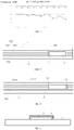
Fig. 1 is a schematic diagram of an electronic device with a display panel according to an exemplary embodiment. -
Fig. 2 is a partial schematic diagram of an electronic device with a display panel according to an exemplary embodiment. -
Fig. 3 is a graph illustrating sound pressure comparison between a display side and a non-display side of the electronic device inFig. 1 . -
Fig. 4 is a partial schematic diagram of another electronic device with a display panel according to an exemplary embodiment. -
Fig. 5 is a partial schematic diagram of still another electronic device with a display panel according to an exemplary embodiment. -
Fig. 6 is a partial schematic diagram of yet another electronic device with a display panel according to an exemplary embodiment. - Exemplary embodiments will be described in detail, and examples of the embodiments will be shown in the drawings. When the following description relates to the drawings, the same numbers in different drawings represent the same or similar elements unless otherwise indicated. The implementations described in the following exemplary embodiments do not represent all implementations consistent with the present disclosure. Instead, they are only examples of devices and methods consistent with some aspects of the present disclosure as detailed in the appended claims.
- Terms used in the present disclosure are only for the purpose of describing specific embodiments, and are not intended to limit the present disclosure. As used in the specification and the appended claims, "a/an," "said" and "the" in singular forms are also intended to include plural forms, unless otherwise clearly indicated in the context. It should also be understood that the term "and/or" used herein represents and includes any and all possible combinations of one or more associated listed items.
- It should be understood that although terms such as "first," "second," and "third" may be used to describe various kinds of information in the present disclosure, such information shall not be limited by these terms. These terms are only used to distinguish information of the same type from each other. For example, without departing from the scope of the present disclosure, the first information may also be referred to as the second information, and similarly, the second information may also be referred to as the first information. Depending on the context, the term "if' used here may be interpreted as "when" or "upon" or "in response to determining."
-
Fig. 1 is a schematic diagram of anelectronic device 100 according to an exemplary embodiment, andFig. 2 is a partial schematic diagram of anelectronic device 100 according to an exemplary embodiment. As shown inFig. 1 and Fig. 2 , theelectronic device 100 may include adisplay panel assembly 1, a piezoelectric sound-generatingunit 2 and astructural member 3. Thedisplay panel assembly 1 may include aflexible display layer 11 and asupport layer 12 stacked on theflexible display layer 11. As shown inFig. 2 , the piezoelectric sound-generatingunit 2 may be bonded to thesupport layer 12 along a thickness direction of thedisplay panel assembly 1. Specifically, the piezoelectric sound-generatingunit 2 may be bonded to thesupport layer 12 through afirst tape 4. Thestructural member 3 may include a first avoidinggroove 31. Thesupport layer 12 may also be bonded to thestructural member 3 to close the first avoidinggroove 31. The piezoelectric sound-generatingunit 2 is connected to an area, which closes the first avoidinggroove 31, of thesupport layer 12, such that a cavity is defined by thesupport layer 12 and thestructural member 3, and the piezoelectric sound-generatingunit 2 is arranged in the cavity. In a thickness direction of theelectronic device 100, there is a gap between thestructural member 3 and the piezoelectric sound-generatingunit 2, to prevent vibration from propagating in a direction away from thedisplay panel assembly 1, resulting in sound leakage. - Based on an application scenario when a user is holding the electronic device and talking, the
flexible display layer 11 usually faces the user's face and a back of the electronic device faces the ambient environment, such that a sound pressure condition on a first side where theflexible display layer 11 is located and a sound pressure condition on a second side away from theflexible display layer 11 are obtained, as shown inFig. 3 . The difference between sound pressure on the first side where theflexible display layer 11 is located and sound pressure on the second side away from theflexible display layer 11 is obtained by using the sound pressure condition on the first side where theflexible display layer 11 is located as a horizontal reference line. As shown inFig. 3 , the sound pressure difference is substantially between -10dB and -15dB, which may reduce the sound leakage. - In an embodiment shown in
Fig. 2 , the piezoelectric sound-generatingunit 2 may include a piezoelectric film sound-generating unit or a piezoelectric ceramic sound-generating unit. The piezoelectric ceramic sound-generating unit may include a piezoelectric ceramic sheet. The piezoelectric ceramic sheet may include a lead zirconate titanate sheet. The piezoelectric film sound-generating unit may include a piezoelectric material layer, and the piezoelectric material layer may include a polyvinylidene fluoride film layer; or the piezoelectric material layer may include a polyvinylidene fluoride film composite layer, for example, a composite film layer of a polyvinylidene fluoride film and carbon nanotubes, or a composite film layer of a polyvinylidene fluoride film and piezoelectric ceramic; or the piezoelectric material layer may include a polyvinylidene fluoride film copolymer, such as a PVDF+TrFE (polyvinylidene fluoride-trifluoroethylene) copolymer. - In the embodiment of
Fig. 2 , an example in which the piezoelectric sound-generatingunit 2 is connected to a side of thesupport layer 12 away from theflexible display layer 11 is illustrated. In other embodiments, as shown inFig. 4 , thesupport layer 12 may include anaccommodation chamber 121 extending from the side away from theflexible display layer 11 toward theflexible display layer 11. Thestructural member 3 may be connected to the side of thesupport layer 12 away from theflexible display layer 11 to seal and cover theaccommodation chamber 121, to form a cavity. The piezoelectric sound-generatingunit 2 may be arranged in theaccommodation chamber 121. When theaccommodation chamber 121 extends to theflexible display layer 11, the piezoelectric sound-generatingunit 2 may be connected to theflexible display layer 11. When theaccommodation chamber 121 does not extend to the flexible display layer, the piezoelectric sound-generatingunit 2 may be connected to thesupport layer 12, to shorten a vibration propagation path to a display side of theflexible display layer 11 and improve the efficiency of sound generation. - Specifically, as shown in
Fig. 4 , thesupport layer 12 may include abonding layer 122 and amain body layer 123. Thebonding layer 122 may bond themain body layer 123 with theflexible display layer 11. Themain body layer 123 may include afoam layer 1231 and acopper foil layer 1232. In other embodiments, themain body layer 123 may also include afoam layer 1231 or acopper foil layer 1232. Theaccommodation chamber 121 penetrates thebonding layer 122 and themain body layer 123, and the piezoelectric sound-generatingunit 2 may be connected to theflexible display layer 11 through asecond tape 5. In another embodiment, as shown inFig. 5 , theaccommodation chamber 121 may penetrate themain body layer 123, and the piezoelectric sound-generatingunit 2 may be bonded to thebonding layer 122, in which thebonding layer 122 may include a light-shielding bonding layer, to avoid light leakage of theflexible display layer 11 by using a shielding function of the light-shielding bonding layer, compared with technical solution shown inFig. 4 . - In an embodiment shown in
Fig. 4 , the piezoelectric sound-generatingunit 2 has a thickness less than a depth of theaccommodation chamber 121, and a side of thestructural member 3 towards thesupport layer 12 may be planar to close theaccommodation chamber 121, which can maintain the integrity of thestructural member 3 and avoid weakening the strength of thestructural member 3. Especially when thestructural member 3 is a middle frame of theelectronic device 100, the overall strength of theelectronic device 100 can be improved. However, in some other embodiments, as shown inFig. 5 , if the thickness of the piezoelectric sound-generatingunit 2 is greater than the depth of theaccommodation chamber 121, thestructural member 3 may include a second avoidinggroove 32 recessed from a first side of thestructural member 3 towards thesupport layer 12 to a second side of thestructural member 3 away from thesupport layer 12, and the second avoidinggroove 32 is in communication with theaccommodation chamber 121. In a depth direction of theaccommodation chamber 121, there is a gap between the piezoelectric sound-generatingunit 2 and the second avoidinggroove 32, to reduce the vibration propagation away from theflexible display layer 11 and the sound leakage. - In the embodiment of
Fig. 4 , an example in which the piezoelectric sound-generatingunit 2 is connected with theflexible display layer 11 and the thickness of the piezoelectric sound-generatingunit 2 is less than the depth of theaccommodation chamber 121 is illustrated. In an embodiment ofFig. 5 , an example in which the piezoelectric sound-generatingunit 2 is connected with thebonding layer 122 and the thickness of the piezoelectric sound-generatingunit 2 is greater than the depth of theaccommodation chamber 121 is illustrated. In other embodiments, the piezoelectric sound-generatingunit 2 may be connected with theflexible display layer 11 and the thickness of the piezoelectric sound-generatingunit 2 is greater than the depth of theaccommodation chamber 121; the piezoelectric sound-generatingunit 2 is connected with thebonding layer 122 and the thickness of the piezoelectric sound-generatingunit 2 is less than the depth of theaccommodation chamber 121, which is not limited by the present disclosure. - In the above embodiments, the
structural member 3 may be the middle frame of theelectronic device 100. In other embodiments, thestructural member 3 may also be other parts, which is not limited by the present disclosure. The above description illustrates a technical solution in which thestructural member 3 and thedisplay panel assembly 1 together define a cavity to reduce sound leakage. In other embodiments, as shown inFig. 6 , thestructural member 3 may also be connected to the piezoelectric sound-generatingunit 2, and an avoiding area may be formed on thestructural member 3, so that after thestructural member 3 is connected to the piezoelectric sound-generatingunit 2, a separation distance between thestructural member 3 and the piezoelectric sound-generatingunit 2 may be greater than zero. Thestructural member 3 may include a middle frame to avoid the vibration propagation in a direction away from theflexible display layer 11. The piezoelectric sound-generatingunit 2 connected to thestructural member 3 may be connected with the side of thesupport layer 12 away from theflexible display layer 11 through a tape, or the piezoelectric sound-generatingunit 2 may also be arranged in the accommodation chamber of thesupport layer 12, to shorten the vibration propagation path and improve the efficiency of sound generation. - In various embodiments described above, in the thickness direction of the electronic device, the gap between the
structural member 3 and the piezoelectric sound-generatingunit 2 is greater than 0.08 mm and less than 0.2 mm, to avoid a poor effect of preventing sound leakage due to a too small gap, and avoid an increase in the overall thickness of the electronic device due to a too large gap. - Other examples of the present disclosure will be apparent to those skilled in the art from consideration of the specification and practice of the present disclosure. The present disclosure is intended to cover any change, use or adaptation of the present disclosure, which complies with the general principles of the present disclosure and includes common knowledge or conventional technical means in the art that are not disclosed herein. The specification and examples are considered to be merely exemplary, and the true scope of the present disclosure are indicated by the following claims.
- It should be understood that the present disclosure is not limited to the specific structures described above and shown in the accompanying drawings, and various modifications and changes may be made without departing from the scope of the present disclosure. The scope of the present disclosure is limited only by the appended claims.
Claims (15)
- An electronic device (100), comprising:a display panel assembly (1);a piezoelectric sound-generating unit (2) bonded to the display panel assembly (1) along a thickness direction of the electronic device (100); anda structural member (3) connected to the display panel assembly (1) to define a cavity having the piezoelectric sound-generating unit (2) arranged in the cavity; or connected to the piezoelectric sound-generating unit (2);wherein a gap exists between the structural member (3) and the piezoelectric sound-generating unit (2) in the thickness direction of the electronic device (100).
- The electronic device (100) according to claim 1, wherein the display panel assembly (1) comprises:a flexible display layer (11); anda support layer (12) bonded to the flexible display layer (11) along the thickness direction of the electronic device (100), the piezoelectric sound-generating unit (2) being connected to the flexible display layer (11) or the support layer (12).
- The electronic device (100) according to claim 2, wherein the structural member (3) comprises a first avoiding groove (31), and the support layer (12) is connected to the structural member (3) to seal the first avoiding groove (31), to form the cavity, wherein the piezoelectric sound-generating unit (2) is connected to an area, sealing the first avoiding groove (31), of the support layer (12).
- The electronic device (100) according to claim 2, wherein the support layer (12) comprises an accommodation chamber (121) extending from a side of the support layer (12) away from the flexible display layer (11) towards the flexible display layer (11), and the piezoelectric sound-generating unit (2) is arranged in the accommodation chamber (121) and connected to the flexible display layer (11) or the support layer (12);
wherein preferably the structural member (3) is connected to the side of the support layer (12) away from the flexible display layer (11) to seal the accommodation chamber (121), to form the cavity. - The electronic device (100) according to claim 4, wherein the support layer (12) comprises a bonding layer (122) and a main body layer (123), and the bonding layer (122) bonds the main body layer (123) with the flexible display layer (11);
the accommodation chamber (121) penetrates the bonding layer (122) and the main body layer (123), and the piezoelectric sound-generating unit (2) is connected to the flexible display layer (11). - The electronic device (100) according to claim 4, wherein the support layer (12) comprises a bonding layer (122) and a main body layer (123), and the bonding layer (122) bonds the main body layer (123) with the flexible display layer (11); the accommodation chamber (121) penetrates the main body layer (123), and the piezoelectric sound-generating unit (2) is connected to the bonding layer (122), wherein the bonding layer (122) comprises a light-shielding bonding layer.
- The electronic device (100) according to any of claims 4 to 6, wherein the piezoelectric sound-generating unit (2) has a thickness less than a depth of the accommodation chamber (121), and a side of the structural member (3) towards the support layer (12) is planar.
- The electronic device (100) according to any of claims 4 to 6, wherein the piezoelectric sound-generating unit (2) has a thickness greater than a depth of the accommodation chamber (121), and the structural member (3) comprises a second avoiding groove (32) recessed from a first side of the structural member (3) towards the support layer (12) to a second side of the structural member (3) away from the support layer (12), wherein the second avoiding groove (32) is in communication with the accommodation chamber (121) to form the cavity.
- The electronic device (100) according to any one of claims 1 to 8, wherein the structural member (3) comprises a middle frame and /or wherein the cavity has a height of greater than 0.08 mm and less than 0.2 mm in a thickness direction of the piezoelectric sound-generating unit (2).
- The electronic device (100) according to any one of claims 1 to 9, wherein the piezoelectric sound-generating unit (2) comprises a piezoelectric ceramic unit or a piezoelectric film unit.
- The electronic device (100) according to claim 10, wherein the piezoelectric ceramic unit comprises a piezoelectric ceramic sheet, and the piezoelectric ceramic sheet comprises a lead zirconate titanate sheet.
- The electronic device (100) according to claim 10, wherein the piezoelectric film unit comprises a piezoelectric material layer, and
wherein the piezoelectric material layer comprises a polyvinylidene fluoride film layer, a polyvinylidene fluoride film composite layer, or a polyvinylidene fluoride film copolymer. - The electronic device (100) according to any one of claims 4 to 12, wherein the support layer (12) comprises a bonding layer (122) and a main body layer (123), and the main body layer (123) comprises at least one of a foam layer (1231) and a copper foil layer (1232).
- The electronic device (100) according to any one of claims 8 to 13, wherein a gap exists between the piezoelectric sound-generating unit (2) and the second avoiding groove (32) in a depth direction of the accommodation chamber (121).
- The electronic device (100) according to any one of claims 2 to 14, wherein a difference between sound pressure on a first side where the flexible display layer (11) is located and sound pressure on a second side away from the flexible display layer (11) is between -10dB and -15dB.
Applications Claiming Priority (1)
| Application Number | Priority Date | Filing Date | Title |
|---|---|---|---|
| CN202110130198.5A CN114827318B (en) | 2021-01-29 | 2021-01-29 | electronic devices |
Publications (2)
| Publication Number | Publication Date |
|---|---|
| EP4037334A1 true EP4037334A1 (en) | 2022-08-03 |
| EP4037334B1 EP4037334B1 (en) | 2026-02-25 |
Family
ID=76730435
Family Applications (1)
| Application Number | Title | Priority Date | Filing Date |
|---|---|---|---|
| EP21182898.3A Active EP4037334B1 (en) | 2021-01-29 | 2021-06-30 | Electronic device with display panel |
Country Status (5)
| Country | Link |
|---|---|
| US (1) | US11785125B2 (en) |
| EP (1) | EP4037334B1 (en) |
| JP (1) | JP7245290B2 (en) |
| KR (1) | KR102593050B1 (en) |
| CN (1) | CN114827318B (en) |
Families Citing this family (1)
| Publication number | Priority date | Publication date | Assignee | Title |
|---|---|---|---|---|
| WO2023000795A1 (en) * | 2021-07-23 | 2023-01-26 | 北京荣耀终端有限公司 | Audio playing method, failure detection method for screen sound-production device, and electronic apparatus |
Citations (3)
| Publication number | Priority date | Publication date | Assignee | Title |
|---|---|---|---|---|
| US20190227603A1 (en) * | 2018-01-23 | 2019-07-25 | Samsung Display Co., Ltd. | Display device |
| US20200004364A1 (en) * | 2018-06-27 | 2020-01-02 | Samsung Display Co., Ltd. | Panel bottom member and display device including the same |
| US20200293084A1 (en) * | 2017-08-10 | 2020-09-17 | Samsung Display Co., Ltd. | Display panel, bracket and display device including the same |
Family Cites Families (20)
| Publication number | Priority date | Publication date | Assignee | Title |
|---|---|---|---|---|
| JP2007228610A (en) * | 2007-03-30 | 2007-09-06 | Nec Tokin Corp | Acoustic vibration generating element |
| CN201616895U (en) | 2010-02-08 | 2010-10-27 | 华为终端有限公司 | Sound cavity and electronic equipment |
| JP2013255212A (en) | 2011-09-13 | 2013-12-19 | Kddi Corp | Telephone call device |
| JP5968050B2 (en) * | 2012-04-26 | 2016-08-10 | 京セラ株式会社 | Electronics |
| JP6151490B2 (en) * | 2012-07-27 | 2017-06-21 | 京セラ株式会社 | Electronic device mounting member and combination of electronic device and mounting member |
| JP6148122B2 (en) * | 2013-08-30 | 2017-06-14 | 京セラ株式会社 | Electronics |
| KR102204384B1 (en) | 2013-09-16 | 2021-01-18 | 삼성디스플레이 주식회사 | Display device |
| KR102367975B1 (en) * | 2017-07-06 | 2022-02-25 | 삼성디스플레이 주식회사 | Panel bottom member and display device including the same |
| KR101880465B1 (en) * | 2017-09-22 | 2018-07-20 | 엘지전자 주식회사 | Mobile terminal |
| CN108881523B (en) * | 2018-04-28 | 2020-10-16 | 歌尔股份有限公司 | Electronic display device and electronic device |
| CN108810765B (en) * | 2018-08-01 | 2019-09-06 | 刘博文 | Electronic display devices and electronic devices |
| CN109842701B (en) * | 2018-12-24 | 2023-11-17 | 歌尔股份有限公司 | Screen vibration sounding device and electronic product |
| KR102676694B1 (en) * | 2019-01-09 | 2024-06-19 | 삼성전자주식회사 | Electronic device with display panel speaker |
| US11476883B2 (en) * | 2019-02-14 | 2022-10-18 | Apple Inc. | Electronic devices having optical and audio components |
| TWI861847B (en) | 2019-02-28 | 2024-11-11 | 南韓商樂金顯示科技股份有限公司 | Electronic apparatus |
| CN110234058A (en) * | 2019-05-23 | 2019-09-13 | 武汉华星光电技术有限公司 | A kind of liquid crystal display die set and mobile terminal |
| CN110187538B (en) * | 2019-06-04 | 2022-02-22 | 武汉华星光电技术有限公司 | Display device |
| CN110493697A (en) * | 2019-07-31 | 2019-11-22 | 武汉华星光电技术有限公司 | Vibration sounding type display panel |
| CN111371930A (en) * | 2020-02-22 | 2020-07-03 | 深圳市泰衡诺科技有限公司 | Screen sound production device and electronic equipment |
| CN211720577U (en) * | 2020-04-29 | 2020-10-20 | 北京小米移动软件有限公司 | Screen module and electronic equipment |
-
2021
- 2021-01-29 CN CN202110130198.5A patent/CN114827318B/en active Active
- 2021-06-25 KR KR1020210083237A patent/KR102593050B1/en active Active
- 2021-06-29 US US17/362,596 patent/US11785125B2/en active Active
- 2021-06-30 JP JP2021108712A patent/JP7245290B2/en active Active
- 2021-06-30 EP EP21182898.3A patent/EP4037334B1/en active Active
Patent Citations (3)
| Publication number | Priority date | Publication date | Assignee | Title |
|---|---|---|---|---|
| US20200293084A1 (en) * | 2017-08-10 | 2020-09-17 | Samsung Display Co., Ltd. | Display panel, bracket and display device including the same |
| US20190227603A1 (en) * | 2018-01-23 | 2019-07-25 | Samsung Display Co., Ltd. | Display device |
| US20200004364A1 (en) * | 2018-06-27 | 2020-01-02 | Samsung Display Co., Ltd. | Panel bottom member and display device including the same |
Also Published As
| Publication number | Publication date |
|---|---|
| US20220247847A1 (en) | 2022-08-04 |
| US11785125B2 (en) | 2023-10-10 |
| CN114827318A (en) | 2022-07-29 |
| EP4037334B1 (en) | 2026-02-25 |
| KR20220110035A (en) | 2022-08-05 |
| KR102593050B1 (en) | 2023-10-25 |
| JP2022117388A (en) | 2022-08-10 |
| JP7245290B2 (en) | 2023-03-23 |
| CN114827318B (en) | 2025-10-03 |
Similar Documents
| Publication | Publication Date | Title |
|---|---|---|
| JP7708841B2 (en) | Display device | |
| CN110351402B (en) | Display module and mobile terminal | |
| KR102530589B1 (en) | Display apparatus and computing apparatus using the same | |
| US20110317868A1 (en) | Electroacoustic transducer | |
| WO2021129263A1 (en) | Loudspeaker inner core, loudspeaker module and electronic device | |
| KR20190081969A (en) | Display apparatus | |
| WO2024001979A1 (en) | Electronic device | |
| WO2020020129A1 (en) | Sound generation structure, and terminal | |
| CN110047392A (en) | A kind of display device | |
| US11937060B2 (en) | Surface sound-emitting apparatus and electronic device | |
| WO2020232947A1 (en) | Liquid crystal display module and mobile terminal | |
| KR102689715B1 (en) | Display apparatus | |
| US11785125B2 (en) | Electronic device | |
| JP5986417B2 (en) | Electronics | |
| CN211720577U (en) | Screen module and electronic equipment | |
| US20220014854A1 (en) | Display device | |
| US8565470B2 (en) | Electroacoustic transducer | |
| CN108810678B (en) | Mobile terminal | |
| CN217935881U (en) | Pickup structure and electronic equipment | |
| JP4642335B2 (en) | Speaker, speaker module, and electronic device using the same | |
| JP5865774B2 (en) | Electronic device, control method, and control program | |
| WO2025050930A1 (en) | Electronic device | |
| US12604136B2 (en) | Assembled screen unit and display module | |
| JP2013219720A (en) | Electronic apparatus | |
| JP4196104B2 (en) | Speaker |
Legal Events
| Date | Code | Title | Description |
|---|---|---|---|
| PUAI | Public reference made under article 153(3) epc to a published international application that has entered the european phase |
Free format text: ORIGINAL CODE: 0009012 |
|
| STAA | Information on the status of an ep patent application or granted ep patent |
Free format text: STATUS: THE APPLICATION HAS BEEN PUBLISHED |
|
| AK | Designated contracting states |
Kind code of ref document: A1 Designated state(s): AL AT BE BG CH CY CZ DE DK EE ES FI FR GB GR HR HU IE IS IT LI LT LU LV MC MK MT NL NO PL PT RO RS SE SI SK SM TR |
|
| STAA | Information on the status of an ep patent application or granted ep patent |
Free format text: STATUS: REQUEST FOR EXAMINATION WAS MADE |
|
| 17P | Request for examination filed |
Effective date: 20230119 |
|
| RBV | Designated contracting states (corrected) |
Designated state(s): AL AT BE BG CH CY CZ DE DK EE ES FI FR GB GR HR HU IE IS IT LI LT LU LV MC MK MT NL NO PL PT RO RS SE SI SK SM TR |
|
| STAA | Information on the status of an ep patent application or granted ep patent |
Free format text: STATUS: EXAMINATION IS IN PROGRESS |
|
| 17Q | First examination report despatched |
Effective date: 20240402 |
|
| GRAP | Despatch of communication of intention to grant a patent |
Free format text: ORIGINAL CODE: EPIDOSNIGR1 |
|
| STAA | Information on the status of an ep patent application or granted ep patent |
Free format text: STATUS: GRANT OF PATENT IS INTENDED |
|
| INTG | Intention to grant announced |
Effective date: 20251010 |
|
| GRAS | Grant fee paid |
Free format text: ORIGINAL CODE: EPIDOSNIGR3 |
|
| GRAA | (expected) grant |
Free format text: ORIGINAL CODE: 0009210 |
|
| STAA | Information on the status of an ep patent application or granted ep patent |
Free format text: STATUS: THE PATENT HAS BEEN GRANTED |
|
| AK | Designated contracting states |
Kind code of ref document: B1 Designated state(s): AL AT BE BG CH CY CZ DE DK EE ES FI FR GB GR HR HU IE IS IT LI LT LU LV MC MK MT NL NO PL PT RO RS SE SI SK SM TR |
|
| REG | Reference to a national code |
Ref country code: CH Ref legal event code: F10 Free format text: ST27 STATUS EVENT CODE: U-0-0-F10-F00 (AS PROVIDED BY THE NATIONAL OFFICE) Effective date: 20260225 Ref country code: GB Ref legal event code: FG4D |
|
| REG | Reference to a national code |
Ref country code: DE Ref legal event code: R096 Ref document number: 602021048554 Country of ref document: DE |
|
| REG | Reference to a national code |
Ref country code: IE Ref legal event code: FG4D |