EP4037212A1 - Controller-to-controller interface for multi-layer network abstraction - Google Patents
Controller-to-controller interface for multi-layer network abstraction Download PDFInfo
- Publication number
- EP4037212A1 EP4037212A1 EP22162323.4A EP22162323A EP4037212A1 EP 4037212 A1 EP4037212 A1 EP 4037212A1 EP 22162323 A EP22162323 A EP 22162323A EP 4037212 A1 EP4037212 A1 EP 4037212A1
- Authority
- EP
- European Patent Office
- Prior art keywords
- network
- controller
- layer
- format
- topology
- Prior art date
- Legal status (The legal status is an assumption and is not a legal conclusion. Google has not performed a legal analysis and makes no representation as to the accuracy of the status listed.)
- Granted
Links
Images



Classifications
-
- H—ELECTRICITY
- H04—ELECTRIC COMMUNICATION TECHNIQUE
- H04L—TRANSMISSION OF DIGITAL INFORMATION, e.g. TELEGRAPHIC COMMUNICATION
- H04L69/00—Network arrangements, protocols or services independent of the application payload and not provided for in the other groups of this subclass
- H04L69/08—Protocols for interworking; Protocol conversion
-
- H—ELECTRICITY
- H04—ELECTRIC COMMUNICATION TECHNIQUE
- H04L—TRANSMISSION OF DIGITAL INFORMATION, e.g. TELEGRAPHIC COMMUNICATION
- H04L41/00—Arrangements for maintenance, administration or management of data switching networks, e.g. of packet switching networks
- H04L41/12—Discovery or management of network topologies
-
- H—ELECTRICITY
- H04—ELECTRIC COMMUNICATION TECHNIQUE
- H04L—TRANSMISSION OF DIGITAL INFORMATION, e.g. TELEGRAPHIC COMMUNICATION
- H04L43/00—Arrangements for monitoring or testing data switching networks
- H04L43/06—Generation of reports
-
- H—ELECTRICITY
- H04—ELECTRIC COMMUNICATION TECHNIQUE
- H04L—TRANSMISSION OF DIGITAL INFORMATION, e.g. TELEGRAPHIC COMMUNICATION
- H04L67/00—Network arrangements or protocols for supporting network services or applications
- H04L67/50—Network services
- H04L67/56—Provisioning of proxy services
- H04L67/565—Conversion or adaptation of application format or content
-
- H—ELECTRICITY
- H04—ELECTRIC COMMUNICATION TECHNIQUE
- H04L—TRANSMISSION OF DIGITAL INFORMATION, e.g. TELEGRAPHIC COMMUNICATION
- H04L69/00—Network arrangements, protocols or services independent of the application payload and not provided for in the other groups of this subclass
- H04L69/18—Multiprotocol handlers, e.g. single devices capable of handling multiple protocols
-
- H—ELECTRICITY
- H04—ELECTRIC COMMUNICATION TECHNIQUE
- H04L—TRANSMISSION OF DIGITAL INFORMATION, e.g. TELEGRAPHIC COMMUNICATION
- H04L69/00—Network arrangements, protocols or services independent of the application payload and not provided for in the other groups of this subclass
- H04L69/30—Definitions, standards or architectural aspects of layered protocol stacks
- H04L69/32—Architecture of open systems interconnection [OSI] 7-layer type protocol stacks, e.g. the interfaces between the data link level and the physical level
- H04L69/322—Intralayer communication protocols among peer entities or protocol data unit [PDU] definitions
-
- H—ELECTRICITY
- H04—ELECTRIC COMMUNICATION TECHNIQUE
- H04L—TRANSMISSION OF DIGITAL INFORMATION, e.g. TELEGRAPHIC COMMUNICATION
- H04L49/00—Packet switching elements
- H04L49/60—Software-defined switches
- H04L49/602—Multilayer or multiprotocol switching, e.g. IP switching
Definitions
- Some embodiments described herein relate generally to network systems, and more particularly, to systems and methods relating to abstracting layers of a multi-layer network.
- Multi-layer networks have been widely used as a way of organizing network resources in a number of different ways to describe different network functionality and/or purposes.
- Each layer (also described herein as a domain) in a network can use different foundational technologies, which may not be inherently compatible with one another.
- optical network layers and IP network layers often use different communication protocols, represent links between network devices differently, are controlled differently, and/or the like.
- GPLS Generalized Multi-Protocol Label Switching
- LMP Link Management Protocol
- RVP Resource Reservation Protocol
- OSPF Open Shortest Path First
- the present disclosure can provide systems and methods that can allow network layers to communicate and share information with each other, while allowing for the network layers to continue to use protocols, network representation formats, and/or the like that are more specifically suited for the particular network layer.
- network layers can use the combination of a controller-to-controller interface (CCI) and a layer mapping function (LMF) module in tandem with various network inputs, to send, receive, and translate various communications between network layers.
- CCI controller-to-controller interface
- LMF layer mapping function
- the CCI and LMF at a first network controller at a first network layer can be used to translate network topology maps and/or like domain link representations into a common link abstraction model (CAM).
- the CAM can be interpreted by any of the network layers via their own CCI, and/or can be used to translate ingoing and/or outgoing communications into a format that can be interpreted by the recipient of the data.
- Some implementations are directed to a system comprising a network entity at a first layer of a multilayer network, the entity at the first layer configured to receive a request for a network topology from a network entity at a second layer of a multilayer network.
- the network entity can use a layer mapping function module operatively coupled to the network entity at the first layer and configured to generate a translation protocol.
- the translation protocol is configured to determine common attributes between a first topology format and a second topology format.
- the network entity at the first layer of the multilayer network is configured to use the translation protocol to convert a topology map in the first topology format into a topology map in a third topology format.
- a multilayer network translation interface module is configured to use the topology map in the third topology format to generate a topology map in the second topology format.
- the network entity at the first layer is configured to send the topology map in the second topology format to the network entity at the second layer such that the entity at the second layer determines a path between a first network node and a second network node based on the topology map in the second topology format.
- a system comprises a controller at a first layer of a multilayer network including a layer mapping function module.
- the layer mapping function module is configured to translate a network topology map in a first format and at the first layer of the multilayer network into a second format in response to a request for a network topology from a controller at a second layer.
- the controller at the first layer can be further configured to provide the network topology map in the second format to a controller-to-controller interface module configured to convert the network topology map to a third format and provide the network topology map in the third format to the controller at the second layer.
- a method comprises receiving a signal, at a first controller at a first layer of a multilayer network from a second controller at a second layer in the multilayer network, requesting a network topology map in a second layer topology format.
- the method includes, in response to the signal, retrieving a network topology map in a first layer topology format at the first controller.
- the method further comprises translating the network topology map in the first layer topology format into a network topology map in an intermediary topology format using a layer mapping function module at the first controller, and translating the topology map in the intermediary topology format into a topology map in the second layer topology format using a controller-to-controller interface module.
- the method further comprises sending the topology map in the second layer topology format to the second controller.
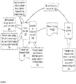
- FIG. 1 is a schematic illustration of a multi-layer network employing a multilayer network translation interface module (e.g., controller-to-controller interface 112a or 112b), according to an embodiment.
- a multi-layer network can include network nodes 102, 104, and 106.
- Each network node 102, 104, and 106 can be a network device including but not limited to a network switch, a network router, a network storage device, a network access device, and/or a similar network computing device.
- Each network node can include at least a memory and a processor and/or a set of processors, and can be configured to store processor-executable instructions in the memory to carry out various functions in the network.
- network nodes 102 , 104, and 106 can be operatively coupled to a network entity, such as a server layer controller 108 (e.g., including but not limited to a data link layer and/or a Layer 2 (L2) controller) situated in the second layer of the multi-layer network.
- a server layer controller 108 e.g., including but not limited to a data link layer and/or a Layer 2 (L2) controller
- Each of the network nodes 102, 104, and 106 can be operatively coupled to the Server controller 108, for example, via a wired connection between at least one port 108c on the Server controller 108, and ports 102a, 104a, and 106a on the network nodes 102, 104, and 106, respectively.
- the second layer of the multi-layer network can be, for example, an optical (e.g., server) layer and/or domain, and can use formats such as but not limited to Device Management Interface (DMI) formats to represent the network topology of the network nodes 102, 104, and 106.
- the Server controller 108 can be a switch device and/or other core server layer device, which can manage incoming and outgoing data in the optical layer of the network, e.g., by managing routing, processing, authenticating, and/or other actions performed on the data in the network.
- the Server controller 108 can include at least a memory 108a and a processor 108b and/or a set of processors, and can be configured to store processor-executable instructions in the memory, the instructions informing the processor of how to manage the network nodes 102, 104, and 106 and/or how to manage data being passed to and/or from the network nodes 102, 104, and 106.
- the Server controller can also include a control module 108e for managing control of network operations and/or data (e.g., such as managing processing and encapsulation of data packets sent between network nodes 102, 104, and 106, and/or controlling network nodes 102, 104, and 106's access to data), and a storage module 108f for persistent data storage. While not shown, multiple Server controllers can exist on the optical layer of the network, and can each be operatively coupled to a number of network nodes.
- a Layer Mapping Function (LMF) module 110 can be a module operative within the Server controller 108, and can be embodied in hardware (e.g., a modular hardware chip including processing hardware and data storage hardware, the modular hardware chip being operatively coupled to a network controller such as Server controller 108) and/or software (e.g., a computer code module and/or a software object) stored or implemented in hardware.
- the LMF module 110 can be configured to define the connectivity between network layers and can extract common attributes between various network layers to define a function, model, and/or method of abstracting data (e.g., topology data) from any of the network layers.
- the LMF module 110 can be configured to provide this function, model, and/or abstraction method to the Server controller 108 to enable the Server controller 108 to define abstractions of data in, for example, an optical layer format (e.g., abstracting network topology representations described in an optical layer format). These abstractions can be translated and/or interpreted by other controllers in other network layers.
- An example of a LMF module model that describes communication between a server layer node (e.g., a network node on the data link and/or L2 layer) and a client layer controller 114 (e.g., including but not limited to a network layer and/or a Layer 3 (L3) controller) can take a form similar to the following:
- an example of an abstraction may be a common link abstraction model (CAM).
- a CAM can be a network layer-dependent model and/or representation of network layer data.
- a CAM derived from a network topology map maintained at an optical layer of the network can specify a manner of describing links between network devices, which can be independent of the structure of the optical network layer and/or other specific constraints and/or properties of the optical network layer.
- the CAM can then be sent to other controllers in other network layers, e.g., can be sent to a Client controller 114, which can interpret the CAM and generate a network topology map in its own client layer format (e.g., an Internet Protocol (IP) layer format defining IP-specific links and network properties).
- IP Internet Protocol
- An example of a CAM description can take a form similar to the following:
- a controller-to-controller interface 112a and 112b can be operatively coupled to the Server controller 110 and the Client controller 114, respectively.
- the controller-to-controller interfaces 112a-b can be embodied in hardware (e.g., a modular hardware chip including processing hardware and data storage hardware, the modular hardware chip being operatively coupled to a network controller) and/or software (e.g., a computer code module stored or implemented in hardware, firmware, processor-executable instructions stored in memory, and/or the like stored or implemented in hardware).
- the controller-to-controller interfaces 112a-b can be configured to transfer the defined CAM to another network controller on another network layer, and/or to receive CAMs from other network controllers.
- the controller-to-controller interfaces 112a-b can also be configured to translate CAMs into formats associated with the particular network layer at which they are received.
- the controller-to-controller interface 112a can be configured to send a CAM representing the network topology map (e.g., defined in an optical layer format and maintained by the Server controller 108) to Client controller 114.
- the controller-to-controller interface 112b can also be configured to receive CAMs, e.g., from the Server controller 108, and translate them into a client layer format (e.g., an IP layer format) for quick processing of the network topology map.
- controller-to-controller interface 112a may automatically translate a CAM into an client layer format, and send the client-layer-formatted network topology map to Client controller 114, such that Client controller may not need a controller-to-controller interface 112b and/or other techniques for interpreting the CAM.
- Client controller 114 may be able to interpret the CAM without the use of a controller-to-controller interface 112b to translate the CAM into a client layer format, and may directly receive the CAM for processing.
- the functionality of a controller-to-controller interface can be included within a controller, and the controller-to-controller interface 112b and Client controller 114 need not be separate devices.
- the LMF module 110 can reside in the controller-to-controller interface 112a instead of the Server controller 108.
- the LMF module 110 can use a modified communication protocol (e.g., a modified version of LMP) to provide the CAM to the Server controller 108, and/or the like.
- a modified communication protocol e.g., a modified version of LMP
- Client controller 114 can be a network controller (e.g., a switch device and/or other core client layer device) situated in the third layer of the multi-layer network.
- the third layer of the multi-layer network can be an IP (e.g., client) layer and/or domain, and can use formats such as but not limited to Link State Database (LSDB) and/or Traffic-Engineering Database (TED) formats in order to represent the network topology of the network nodes 102, 104, and 106.
- LSDB Link State Database
- TED Traffic-Engineering Database
- the Client controller 114 can manage incoming and outgoing data in the IP layer of the network, e.g., by managing routing, processing, authenticating, and/or other actions performed on the data in the network.
- the Client controller 114 can also include at least a memory and a processor and/or a set of processors, and can be configured to store processor-executable instructions in the memory, the instructions informing the processor of how to manage network nodes and/or how to manage data being passed to and/or from the network nodes.
- Client controller 114 can be operatively connected to a controller-to-controller interface 112b, which can receive and/or translate CAMs received by the Client controller 114 into a client layer (e.g., IP layer) format, e.g., an IP layer network topology map format, and/or the like.
- a client layer e.g., IP layer
- Client controller 114 may not be directly coupled to a controller-to-controller interface 112b, and may instead directly receive CAMs and/or IP-layer-formatted network topology map data from the controller-to-controller interface 112a operatively coupled to the Server controller.
- multiple Client controllers can operate on the IP layer of the network, and can each be operatively coupled to at least one Server controller at the optical layer of the network.
- Client controller 114 and/or other Client controllers in the network can also be operatively coupled to network nodes 102, 104, and 106, and/or other network nodes in the network.
- FIGs. 2-6 provide example implementations of the system described in FIG. 1 , it should be understood that the processes and functionality described in FIGs. 2-6 can be implemented using a variety of other network configurations and/or system arrangements, and are not limited to the structure embodied in FIG. 1 .
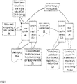
- FIG. 2 is a flow diagram of providing a network topology map to a Client controller from a Server controller with a controller-to-controller interface 112a, according to an embodiment.
- the Server controller 108 can, using the LMF module 110 (e.g., shown in FIG. 1 ), determine common attributes, at 202, between the network topology format used by the optical layer and the Server controller 108, and the network topology format used by the IP layer and the Client controller 114. Determining common attributes can include determining common indicia each layer's format uses to describe a network link in a network topology map, to describe a path between network nodes, and/or the like.
- the LMF module 110 can derive the common attributes based on a comparison of network topology maps in the two layers' formats, based on receiving attributes and/or descriptions of the layers' formats being compared, and/or the like.
- the LMF module 110 can alternatively receive data indicating the common attributes (e.g., from a network administrator, from data embedded in the LMF module 110, and/or the like) instead of determining the attributes on its own.
- the Client controller 114 can also generate and send a network topology map request 204 to the Server controller 108.
- the network topology map request 204 can request a copy of the network topology map maintained by the Server controller 108.
- the Client controller 114 can use the network topology map to determine how to route and/or manage data packets in the network, how to link and/or otherwise associate network nodes, how to generate virtual network nodes to fulfill various network functions, and/or the like.
- the network topology map stored at the Server controller 108 and retrieved, at 206, as a result of the request may not be in a format readable by the Client controller 114 (e.g., the network topology map can be in an optical layer format rather than an IP layer format, and/or the like).
- Storing the network topology map in an optical layer format can allow for faster processing of network information, as it can allow the optical layer to process data using a network topology map in a format that the optical layer can easily interpret, and can allow the optical layer to use optimizations inherent in the optical layer format to process the data.
- the Server controller 108 can use the LMF module 110 to translate, at 208, the network topology map into a CAM 210.
- the LMF module can, for example, generate, as the CAM 210, a representation of the network topology map that uses the attributes common to the two layers' formats to describe the network links and communications.
- Translating the network topology map into a CAM when the network topology map is requested by a controller at another layer allows the optical layer controllers (e.g., the Server controller 108) to maintain the network topology map in a format optimized and/or streamlined for the functionality of the optical layer. Maintaining the network topology map in the optical layer format also allows the optical layer to include attributes and/or information specific to the nature of the optical layer. Translating the CAM also allows the Server controller 108 to still communicate the current topology of the network to other layers. Storing the CAM itself and/or a representation in a single common format would not allow for the same efficiency and/or ability to fully describe the network topology at the optical layer.
- the CAM 210 generated by the LMF module 110 can be sent to a controller-to-controller interface 112a, which can be operatively coupled to the Server controller 108.
- the controller-to-controller interface 112a can be configured to translate, at 212, the CAM into a network topology map 214 in the IP layer format.
- the controller-to-controller interface 112a can also provide the network topology map 214 to the Client controller 114 via a signal to the Client controller 114, which includes a representation of the network topology map 214.
- the Client controller 114 can then determine paths (e.g., optimized paths, shortest paths, fastest paths, and/or the like) between a first network node in the network and a second network node 216 in the network based on the network topology map.
- the CAM 210 can also be sent directly to the Client controller 114, which can be configured to interpret the CAM 210 directly, and/or may be operatively coupled to a second controller-to-controller interface 112b (e.g., see FIGs. 3-4 ), which is configured to translate the CAM into an IP layer format.
- the Client controller 114 can be configured to interpret the CAM 210 directly, and/or may be operatively coupled to a second controller-to-controller interface 112b (e.g., see FIGs. 3-4 ), which is configured to translate the CAM into an IP layer format.
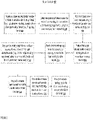
- FIG. 3 is a flow diagram of providing a network topology map to a Client controller 114 operatively coupled to a controller-to-controller interface 112b, from a Server controller 108, according to a second embodiment.
- the Server controller 108 can use a LMF module 110 (e.g., shown in FIG. 1 ) to determine common attributes, at 302, between the layer formats of the Server controller 108 and the Client controller 114.
- the Server controller can also retrieve, at 306, the network topology map in the optical layer format, and the LMF module 110 can use the retrieved network topology map to translate, at 308, the network topology map into a CAM 310.
- the Server controller 108 can send the CAM 310 to the controller-to-controller interface 112b, e.g., via a signal to the controller-to-controller interface 112b including a representation of the CAM 310.
- the controller-to-controller interface 112b can then translate, at 312, the CAM 310 into a network topology map, e.g., in an IP layer format.
- the Client controller 114 can then use the network topology map in the IP layer format to determine, at 316, paths between a first network node in the network and a second network node in the network.
- the Client controller 114 can directly receive the CAM 310, instead of receiving the translated network topology map from the controller-to-controller interface 112b.
- the Client controller 114 can be configured to interpret the CAM 310 directly, e.g., to update a network topology map stored at the Client controller 114, in place of a network topology map in an IP layer format, and/or the like.
- the Client controller 114 can also translate the CAM 310 into a network topology map, e.g., to store and/or process at the Client controller 114.
- FIG. 4 is a flow diagram of providing a network topology map to an Client controller 114 with a controller-to-controller interface 112b from an Server controller 108 with a controller-to-controller interface 112a, according to a third embodiment.
- multiple controllers in the multi-layer network can be operatively coupled to a given controller-to-controller interface configured to translate and/or process network topology maps for the particular controller(s) to which it is attached.
- the controller-to-controller interfaces can also be operatively coupled to a LMF module (not shown in Fig. 4 ), e.g., instead of a controller being operatively coupled to a LMF controller.
- a LMF module not shown in Fig. 4
- the Server controller 108 can determine, at 402, common attributes between the optical layer format and the IP layer format.
- the Server controller 108 can retrieve, at 406, its representation of the network topology map 408 (e.g., in the optical layer format), and can provide the network topology map 408 to the controller-to-controller interface 112a.
- the controller-to-controller interface 112a can translate, at 410, the network topology map 408 into a CAM 412 of the network topology map, e.g., via the LMF module operatively coupled to the controller-to-controller interface 112a.
- the controller-to-controller interface 112a can send the CAM 412 to the controller-to-controller interface 112b operatively coupled to the Client controller 114.
- the controller-to-controller interface 112b can translate, at 414, the CAM 412 into a network topology map, e.g., in an IP layer format, and can provide the translated network topology map to the Client controller 114.
- the controller-to-controller interface 112b can provide the Client controller 114 with the CAM directly.
- the Client controller 114 can then determine, at 416, paths between a first network node in the network and a second network node in the network.
- FIG. 5 is a flow diagram of providing a network topology map to a Client controller from a Server controller with a controller-to-controller interface, according to an embodiment.
- a Server controller 108 can receive (e.g., at a LMF module 110, and/or directly at the Server controller 108) attributes and/or descriptions relating to an optical layer's network topology format, as well as attributes and/or descriptions relating to an IP layer's network topology format, at 502.
- the LMF module 110 can determine common attributes and/or indicia between the optical layer's and the IP layer's network topology formats, at 504, which can be used later to generate a CAM of the network topology map.
- the Server controller 108 can receive a request from a Client controller 114 for a network topology map, at 506, and can retrieve, in response to the request, a network topology map in an optical layer format, at 508.
- the Server controller 108 can provide, at 510, the network topology map to the LMF module 110.
- the LMF module 110 translates, at 512, the network topology map in the optical layer format into a CAM representing the network topology map, e.g., based on the common attributes derived by the LMF module 110.
- the CAM can be an intermediary network topology map format, which can abstract the layer-specific details of the network topology map stored at the Server controller 108, and can be used to translate the network topology map into other layer formats, and/or to interpret the network topology map at other network layers.
- the LMF 110 can provide, at 514, the CAM to a controller-to-controller interface 112a operatively coupled to the Server controller 108.
- the controller-to-controller interface 112a can be configured to translate the common layer abstraction model into a network topology map in an IP layer format, at 516.
- the network topology map in an IP layer and/or other client layer topology format can then be provided, at 518, to the Client controller 114 for processing (e.g., to determine how to route data packets, and/or the like).
- the controller-to-controller interface 112a can send the CAM directly to the Client controller 114, without translating it into an IP layer format, and the Client controller 114 can directly interpret the CAM to determine paths between network nodes.
- FIG. 6 is a flow diagram of providing a network topology map to a Client controller 114 operatively coupled to a controller-to-controller interface, from a Server controller 108, according to an embodiment.
- a Server controller 108 can receive (e.g., at a LMF module 110, and/or directly at the Server controller 108) attributes and/or descriptions relating to an optical layer's network topology format, as well as attributes and/or descriptions relating to an IP layer's network topology format, at 602.
- the LMF module 110 can determine common attributes and/or indicia between the optical layer's and the IP layer's network topology formats, at 604, which can be used later to generate a CAM of the network topology map.
- the Server controller 108 can receive a request from a Client controller 114 for a network topology map, at 606, and can retrieve, in response to the request, a network topology map in an optical layer format at 608.
- the Server controller 108 can provide, at 610, the network topology map to the LMF module 110, the LMF module 110 being configured to translate, at 612, the network topology map in the optical layer format into a CAM representing the network topology map, e.g., based on the common attributes derived by the LMF module 110.
- the LMF module 110 can be configured to provide, at 614, the CAM to a controller-to-controller interface 112b at the Client controller 114.
- the controller-to-controller interface 112b at the Client controller 114 receives the CAM, at 616, and translates the CAM into a network topology map, at 618, in an IP layer and/or other client layer topology format.
- the network topology map in the IP layer format can then be used by the Client controller to determine paths between a first network node in the network and a second network node in the network, at 620.
- the controller-to-controller interface 112b can provide the CAM directly to the Client controller for processing.
- embodiments herein relate to communications between an optical layer of a multi-layer network and a client layer of a multi-layer network, it should be understood that the embodiments can also be used with controllers on other layers of the multi-layer network.
- Some embodiments described herein relate to devices with a computer-readable medium (also can be referred to as a processor-readable medium or memory) having instructions or computer code thereon for performing various computer-implemented operations.
- the computer-readable medium (or processor-readable medium) may be either transitory or non-transitory, where a medium may be non-transitory in the sense that it does not include transitory propagating signals per se (e.g., a propagating electromagnetic wave carrying information on a transmission medium such as space or a cable).
- the media and computer code also can be referred to as code
- code may be those designed and constructed for the specific purpose or purposes.
- non-transitory computer-readable media include, but are not limited to: magnetic storage media such as hard disks, floppy disks, and magnetic tape; optical storage media such as Compact Disc/Digital Video Discs (CD/DVDs), Compact Disc-Read Only Memories (CD-ROMs), and holographic devices; magneto-optical storage media such as optical disks; carrier wave signal processing modules; and hardware devices that are specially configured to store and execute program code, such as Application-Specific Integrated Circuits (ASICs), Programmable Logic Devices (PLDs), Read-Only Memory (ROM) and Random-Access Memory (RAM) devices.
- ASICs Application-Specific Integrated Circuits
- PLDs Programmable Logic Devices
- ROM Read-Only Memory
- RAM Random-Access Memory
- Other embodiments described herein relate to a computer program product, which can include, for example, the instructions and/or computer code discussed herein.
- a controller at an IP (e.g., client) layer in a multi-layer network can request a network topology map from another controller at an optical (e.g., server) layer in the multi-layer network.
- the controller at the optical layer of the network can use a layer mapping function and common attributes between the formats used to describe the network topology map at the two layers to generate a common layer abstraction model representing the network topology map stored at the controller at the optical layer of the network.
- a controller-to-controller interface can translate and/or send the common layer abstraction model to the controller at the IP layer for processing data on the network.
Landscapes
- Engineering & Computer Science (AREA)
- Computer Networks & Wireless Communication (AREA)
- Signal Processing (AREA)
- Computer Security & Cryptography (AREA)
- Data Exchanges In Wide-Area Networks (AREA)
- Optical Communication System (AREA)
Abstract
Description
- Some embodiments described herein relate generally to network systems, and more particularly, to systems and methods relating to abstracting layers of a multi-layer network.
- Multi-layer networks have been widely used as a way of organizing network resources in a number of different ways to describe different network functionality and/or purposes. Each layer (also described herein as a domain) in a network can use different foundational technologies, which may not be inherently compatible with one another. For example optical network layers and IP network layers often use different communication protocols, represent links between network devices differently, are controlled differently, and/or the like.
- Known networks have historically employed shared cross-layer formats for both optical network layers and IP network layers to represent links between network devices and/or like network attributes. For example, Generalized Multi-Protocol Label Switching (GMPLS) employs a single common control-plane representation for multiple layers of a multi-layer network. It also defines protocols such as Link Management Protocol (LMP), Resource Reservation Protocol (RSVP), and Open Shortest Path First (OSPF) to handle communications within and between network layers. This common representation for blending characteristics between the network layers, however, is often lacking in layer-specific optimizations that allow for faster processing of network functions within a particular layer. Additionally, a single common representation may prevent each layer from being able to evolve independently from other layers in the network, e.g., by requiring that each layer develop according to common constraints defined by the common representation.
- Particular aspects are set out in the appended independent claims.
- Viewed from one perspective, the present disclosure can provide systems and methods that can allow network layers to communicate and share information with each other, while allowing for the network layers to continue to use protocols, network representation formats, and/or the like that are more specifically suited for the particular network layer.
- In some implementations, network layers can use the combination of a controller-to-controller interface (CCI) and a layer mapping function (LMF) module in tandem with various network inputs, to send, receive, and translate various communications between network layers. For example, the CCI and LMF at a first network controller at a first network layer can be used to translate network topology maps and/or like domain link representations into a common link abstraction model (CAM). The CAM can be interpreted by any of the network layers via their own CCI, and/or can be used to translate ingoing and/or outgoing communications into a format that can be interpreted by the recipient of the data.
- Some implementations are directed to a system comprising a network entity at a first layer of a multilayer network, the entity at the first layer configured to receive a request for a network topology from a network entity at a second layer of a multilayer network. The network entity can use a layer mapping function module operatively coupled to the network entity at the first layer and configured to generate a translation protocol. The translation protocol is configured to determine common attributes between a first topology format and a second topology format. The network entity at the first layer of the multilayer network is configured to use the translation protocol to convert a topology map in the first topology format into a topology map in a third topology format. A multilayer network translation interface module is configured to use the topology map in the third topology format to generate a topology map in the second topology format. The network entity at the first layer is configured to send the topology map in the second topology format to the network entity at the second layer such that the entity at the second layer determines a path between a first network node and a second network node based on the topology map in the second topology format.
- In further implementations, a system comprises a controller at a first layer of a multilayer network including a layer mapping function module. The layer mapping function module is configured to translate a network topology map in a first format and at the first layer of the multilayer network into a second format in response to a request for a network topology from a controller at a second layer. The controller at the first layer can be further configured to provide the network topology map in the second format to a controller-to-controller interface module configured to convert the network topology map to a third format and provide the network topology map in the third format to the controller at the second layer.
- In further implementations, a method comprises receiving a signal, at a first controller at a first layer of a multilayer network from a second controller at a second layer in the multilayer network, requesting a network topology map in a second layer topology format. The method includes, in response to the signal, retrieving a network topology map in a first layer topology format at the first controller. The method further comprises translating the network topology map in the first layer topology format into a network topology map in an intermediary topology format using a layer mapping function module at the first controller, and translating the topology map in the intermediary topology format into a topology map in the second layer topology format using a controller-to-controller interface module. Finally, the method further comprises sending the topology map in the second layer topology format to the second controller.
-
-
FIGURE 1 is a schematic illustration of a network employing a controller-to-controller interface, according to an embodiment. -
FIGURE 2 is a flow diagram of providing a network topology map to a Client controller from a Server controller with a controller-to-controller interface, according to a first embodiment. -
FIGURE 3 is a flow diagram of providing a network topology map to a Client controller with a controller-to-controller interface from a Server controller, according to a second embodiment. -
FIGURE 4 is a flow diagram of providing a network topology map to a Client controller with a controller-to-controller interface from a Server controller with a controller-to-controller interface, according to a third embodiment. -
FIGURE 5 is a flow diagram of providing a network topology map to a Client controller from a Server controller with a controller-to-controller interface, according to an embodiment. -
FIGURE 6 is a flow diagram of providing a network topology map to a Client controller with a controller-to-controller interface from a Server controller, according to an embodiment. -
FIG. 1 is a schematic illustration of a multi-layer network employing a multilayer network translation interface module (e.g., controller-to-controller interface network nodes network node - In some implementations,
network nodes network nodes Server controller 108, for example, via a wired connection between at least oneport 108c on theServer controller 108, andports network nodes network nodes Server controller 108 can be a switch device and/or other core server layer device, which can manage incoming and outgoing data in the optical layer of the network, e.g., by managing routing, processing, authenticating, and/or other actions performed on the data in the network. TheServer controller 108 can include at least amemory 108a and aprocessor 108b and/or a set of processors, and can be configured to store processor-executable instructions in the memory, the instructions informing the processor of how to manage thenetwork nodes network nodes control module 108e for managing control of network operations and/or data (e.g., such as managing processing and encapsulation of data packets sent betweennetwork nodes network nodes storage module 108f for persistent data storage. While not shown, multiple Server controllers can exist on the optical layer of the network, and can each be operatively coupled to a number of network nodes. - A Layer Mapping Function (LMF)
module 110 can be a module operative within theServer controller 108, and can be embodied in hardware (e.g., a modular hardware chip including processing hardware and data storage hardware, the modular hardware chip being operatively coupled to a network controller such as Server controller 108) and/or software (e.g., a computer code module and/or a software object) stored or implemented in hardware. TheLMF module 110 can be configured to define the connectivity between network layers and can extract common attributes between various network layers to define a function, model, and/or method of abstracting data (e.g., topology data) from any of the network layers. TheLMF module 110 can be configured to provide this function, model, and/or abstraction method to theServer controller 108 to enable theServer controller 108 to define abstractions of data in, for example, an optical layer format (e.g., abstracting network topology representations described in an optical layer format). These abstractions can be translated and/or interpreted by other controllers in other network layers. An example of a LMF module model that describes communication between a server layer node (e.g., a network node on the data link and/or L2 layer) and a client layer controller 114 (e.g., including but not limited to a network layer and/or a Layer 3 (L3) controller) can take a form similar to the following:
     1.1.1.1 1.1.1.2
     +-------------+ +-----------------+
      | IP Node1 | <-----LMF------>| Optical node |
     +-------------+ +------------------+
     Add: 10.1.1.1 10.1.1.2
     ID: 12345 54321
     100G Ethernet ODU4
     NodeID: 1.1.1.1
     To: 1.1.1.2, LocalIPaddr: 10.1.1.1, RemoteIPaddr: 10.1.1.2
     LocalIfIndex: 12345, RemoteIfIndex: 54321
     Metric: 23
     Bandwidth: 100 Gbps
     Interface Switching Capability:
     Local: Ethernet
     Remote: Lambda
     +------------------------+
      | Optical Controller |----CAM--->
     +------------------------+
      II
     +----------DMI--------------------------------------------+
      I I I
     1.1.1.2 V 1.1.1.3 V V 1.1.1.4
     +-----------------+ +-----------------+ +-----------------+
      I Optical Nodel |<---------->| Optical node2 |<---------->| Optical node3 |
     +-----------------+ +-----------------+ +-----------------+
     <-------------------------link-ABC------------------------ >
     Add: 10.1.2.1 10.1.2.2
     ID: 78901 10987
     100G Lambda Lambda
     NodeID: 1.1.1.2
     To: 1.1.1.4, LocalIPaddr: 10.1.2.1, RemoteIPaddr: 10.1.2.2
     LocalIfIndex: 78901, RemoteIfIndex: 10987
     Metric: 47
     Bandwidth: 100 Gbps
     Interface Switching Capability:
     Local: Lambda
     Remote: Lambda
     Encoding: ODU4
     Attributes:
     SRLG: 5
     Admin-group: Blue
     Protected: False
- [Clause 1] A system, comprising: a network entity at a first layer of a multilayer network, the entity at the first layer configured to receive a request for a network topology from a network entity at a second layer of a multilayer network; a layer mapping function module operatively coupled to the network entity at the first layer and configured to generate a translation protocol,
- the translation protocol configured to determine common attributes between a first topology format and a second topology format, the network entity at the first layer of the multilayer network configured to use the translation protocol to convert a topology map in the first topology format into a topology map in a third topology format; and a multilayer network translation interface module configured to use the topology map in the third topology format to generate a topology map in the second topology format; the network entity at the first layer configured to send the topology map in the second topology format to the network entity at the second layer such that the entity at the second layer determines a path between a first network node and a second network node based on the topology map in the second topology format.
- [Clause 2] The system of
clause 1, wherein the network entity in the first layer of the multilayer network is a first controller in a first layer domain. - [Clause 3] The system of
clause 1 or 2, wherein: the network entity in the first layer of the multilayer network is a first controller in a first layer domain; and the first layer domain is an optical domain on a server layer. - [Clause 4] The system of
clause 1, 2 or 3, wherein: the network entity in the first layer of the multilayer network is a first controller in a first layer domain; and the network entity in the second layer of the multilayer network is a second controller in a second layer domain. - [Clause 5] The system of any preceding clause, wherein: the network entity in the first layer of the multilayer network is a first controller in a first layer do main; the network entity in the second layer of the multilayer network is a second controller in a second layer domain; and the second layer domain is an IP domain on a client layer.
- [Clause 6] The system of any preceding clause, wherein: the first topology format is an optical network topology format; and the second topology format is an internet protocol (IP) topology format.
- [Clause 7] The system of any preceding clause. wherein the third topology format is a common link abstraction model format.
- [Clause 8] A system, comprising: a controller at a first layer of a multilayer network including a layer mapping function module, the layer mapping function module configured to translate a network topology map in a first format and at the first layer of the multilayer network into a second format in response to a request for a network topology from a controller at a second layer; the controller at the first layer configured to provide the network topology map in the second format to a controller-to-controller interface module configured to convert the network topology map to a third format and provide the network topology map in the third format to the controller at the second layer.
- [Clause 9] The system of clause 8, wherein: the first layer is a server layer of the multilayer network, and the server layer is configured to use an optical domain protocol.
- [Clause 10] The system of clause 8 or 9, wherein: the second layer is a client layer of the multilayer network, and the client layer is configured to use an internet protocol (IP) domain protocol.
- [Clause 11] The system of clause 8, 9 or 10, wherein: the first topology format is an optical network topology format; the second topology format is a common link abstraction model format; and the third topology format is an internet protocol (IP) topology format.
- [Clause 12] The system of any of clauses 8 to 11, wherein: the first format is an optical network topology format, the third format is an internet protocol (IP) topology format, and the layer mapping function module is configured to determine common attributes between the optical network topology format and the IP topology format.
- [Clause 13] The system of any of clauses 8 to 12, wherein: the first format is an optical network topology format, the second topology format is a common link abstraction model format; the third format is an internet protocol (IP) topology format, and the common link abstraction model format is configured to describe the network topology map in the optical network topology format using common attributes between the optical network topology format and the IP topology format.
- [Clause 14] A method, comprising: receiving a signal at a first controller at a first layer of a multilayer network from a second controller at a second layer in the multilayer network, the signal requesting a network topology map in a second layer topology format; in response to the signal, retrieving a network topology map in a first layer topology format at the first controller; translating the network topology map in the first layer topology format into a network topology map in an intermediary topology format using a layer mapping function module at the first controller; translating the topology map in the intermediary topology format into a topology map in the second layer topology format using a controller-to-controller interface module; and sending the topology map in the second layer topology format to the second controller.
- [Clause 15] The method of clause 14, wherein: the first layer is a client layer of the multilayer network, and the client layer uses an internet protocol (IP) domain protocol.
- [Clause 16] The method of clause 14 or 15, wherein: the second layer is a server layer of the multilayer network, and the server layer uses an optical domain protocol.
- [Clause 17]. The method of clause 14. 15 or 16, wherein the first layer topology format is an optical network topology format.
- [Clause 18] The method of any of clauses 14 to 17, wherein the second layer topology format is an internet protocol (IP) topology format.
- [Clause 19] The method of any of clauses 14 to 18, wherein the intermediary topology format is a common link abstraction model format.
- [Clause 20] The method of any of clauses 14 to 19, wherein: the second layer topology format is an internet protocol (IP) topology format, the first layer topology format is format an optical network topology, and the layer mapping function module is configured to determine common attributes between the optical network topology format and the IP topology format.
- [Clause 21] A system, comprising: a network entity at a first layer of a multilayer network, the entity at the first layer configured to receive a request for a network topology from a network entity at a second layer of a multilayer network; a layer mapping function module operatively coupled to the network entity at the first layer and configured to generate a translation protocol, the translation protocol configured to determine common attributes between a first topology format and a second topology format, the network entity at the first layer of the multilayer network configured to use the translation protocol to convert a topology map in the first topology format into a topology map in a third topology format; and a multilayer network translation interface module configured to use the topology map in the third topology format to generate a topology map in the second topology format; the network entity at the first layer configured to send the topology map in the second topology format to the network entity at the second layer such that the entity at the second layer determines a path between a first network node and a second network node based on the topology map in the second topology format.
- [Clause 22] The system of clause 21, wherein the network entity in the first layer of the multilayer network is a first controller in a first layer domain.
- [Clause 23] The system of clause 21 or 22, wherein: the network entity in the first layer of the multilayer network is a first controller in a first layer domain; and the first layer domain is an optical domain on a server layer; and/or the network entity in the second layer of the multilayer network is a second controller in a second layer domain, optionally wherein the second layer domain is an IP domain on a client layer.
- [Clause 24] The system any of clauses 21 to 23, wherein: the first topology format is an optical network topology format; and the second topology format is an internet protocol (IP) topology format.
- [Clause 25] The system of any of clauses 21 to 24, wherein the third topology format is a common link abstraction model format.
- [Clause 26] A system, comprising: a controller at a first layer of a multilayer network including a layer mapping function module, the layer mapping function module configured to translate a network topology map in a first format and at the first layer of the multilayer network into a second format in response to a request for a network topology from a controller at a second layer; the controller at the first layer configured to provide the network topology map in the second format to a controller-to-controller interface module configured to convert the network topology map to a third format and provide the network topology map in the third format to the controller at the second layer.
- [Clause 27] The system of clause 26, wherein: the first layer is a server layer of the multilayer network, and the server layer is configured to use an optical domain protocol.
- [Clause 28] The system of clause 26 or 27, wherein: the second layer is a client layer of the multilayer network, and the client layer is configured to use an internet protocol (IP) domain protocol.
- [Clause 29] The system of any of clauses 26 to 28, wherein: the first format is an optical network topology format, the third format is an internet protocol (IP) topology format, and the layer mapping function module is configured to determine common attributes between the optical network topology format and the IP topology format; and/or the second topology format is a common link abstraction model format; optionally wherein the common link abstraction model format is configured to describe the network topology map in the optical network topology format using common attributes between the optical network topology format and the IP topology format.
- [Clause 30] A method, comprising: receiving a signal at a first controller at a first layer of a multilayer network from a second controller at a second layer in the multilayer network, the signal requesting a network topology map in a second layer topology format; in response to the signal, retrieving a network topology map in a first layer topology format at the first controller; translating the network topology map in the first layer topology format into a network topology map in an intermediary topology format using a layer mapping function module at the first controller; translating the topology map in the intermediary topology format into a topology map in the second layer topology format using a controller-to-controller interface module; and sending the topology map in the second layer topology format to the second controller.
- [Clause 31] The method of clause 30, wherein: the first layer is a client layer of the multilayer network, and the client layer uses an internet protocol (IP) domain protocol.
- [Clause 32] The method of clause 30 or 31, wherein: the second layer is a server layer of the multilayer network, and the server layer uses an optical domain protocol.
- [Clause 33] The method of clause 30, 31 or 32, wherein the first layer topology format is an optical network topology format, and/or wherein the second layer topology format is an internet protocol (IP) topology format.
- [Clause 34] The method of any of clauses 30 to 33, wherein the intermediary topology format is a common link abstraction model format.
- [Clause 35] The method of any of clauses 30 to 34, wherein: the second layer topology format is an internet protocol (IP) topology format, the first layer topology format is format an optical network topology, and the layer mapping function module is configured to determine common attributes between the optical network topology format and the IP topology format.
- 1. A system, comprising:
- a controller at a first layer of a multilayer network including a layer mapping function module, the layer mapping function module configured to translate a network topology map in a first format and at the first layer of the multilayer network into a second format in response to a request for a network topology from a controller at a second layer;
- the controller at the first layer configured to provide the network topology map in the second format to a controller-to-controller interface module configured to convert the network topology map to a third format and provide the network topology map in the third format to the controller at the second layer.
- 2. The system of
clause 1, wherein:- the first layer is a server layer of the multilayer network, and
- the server layer is configured to use an optical domain protocol.
- 3. The system of
clause 1 or 2, wherein:- the second layer is a client layer of the multilayer network, and
- the client layer is configured to use an internet protocol (IP) domain protocol.
- 4. The system of
clause 1, 2 or 3, wherein the first format is an optical network topology format, and/or wherein the second format is an internet protocol (IP) topology format. - 5. The system of any of
clause 1 to 4, wherein:- the first format is an optical network topology format,
- the third format is an internet protocol (IP) topology format, and
- the layer mapping function module is configured to determine common attributes between the optical network topology format and the IP topology format.
- 6. The system of any of
clause 1 to 5, wherein:- the first format is an optical network topology format,
- the third format is an internet protocol (IP) topology format, and
- the second format is a common link abstraction model format; optionally wherein the common link abstraction model format is configured to describe the network topology map in the optical network topology format using common attributes between the optical network topology format and the IP topology format.
- 7. The system of any
clauses 1 to 4, wherein the third topology format is a common link abstraction model format. - 8. A method, comprising:
- translating, at a controller at a first layer, a network topology map in a first format and at the first layer of a multilayer network into a second format in response to a request for a network topology from a controller at a second layer; and
- providing, at the controller at the first layer, the network topology map in the second format to a controller-to-controller interface module configured to convert the network topology map to a third format and provide the network topology map in the third format to the controller at the second layer.
- 9. The method of clause 8, wherein:
- the first layer is a server layer of the multilayer network, and
- the server layer is configured to use an optical domain protocol.
- 10. The method of clause 8 or 9, wherein:
- the second layer is a client layer of the multilayer network, and
- the client layer is configured to use an internet protocol (IP) domain protocol.
- 11. The method of clause 8, 9 or 10, wherein the first format is an optical network topology format, and/or wherein the second format is an internet protocol (IP) topology format.
- 12. The method of any of clauses 8 to 11, wherein:
- the first format is an optical network topology format,
- the third format is an internet protocol (IP) topology format, and
- the method further comprising:
determining common attributes between the optical network topology format and the IP topology format.
- 13. The method of any of clauses 8 to 12, wherein:
- the first format is an optical network topology format,
- the third format is an internet protocol (IP) topology format, and
- the second format is a common link abstraction model format; optionally wherein the common link abstraction model format is configured to describe the network topology map in the optical network topology format using common attributes between the optical network topology format and the IP topology format.
- 14. The method of any clauses 8 to 11 wherein the third topology format is a common link abstraction model format.
Claims (15)
- A method, comprising:sending, from a client controller (114) that uses a client layer topology format and is at a first layer of a multilayer network, a request for a network topology map to a server controller (108) that uses an optical network topology format and is at a second layer of the multilayer network, the server controller configured to translate a network topology map in the optical network topology format included in the server controller to a network topology map in a common link abstraction model format;receiving, at the client controller, a network topology map in the client layer topology format from a controller-to-controller interface (112a, 112b) configured to generate the network topology map in the client layer topology format based on the network topology map in the common link abstraction model; anddetermining, at the client controller, at least one path between a first network node (102) and a second network node (104) using the network topology map in the client layer topology format.
- The method of claim 1, wherein the client layer topology format is an Internet Protocol, IP, layer format.
- The method of any preceding claim, wherein the controller-to-controller interface and the client controller are not separate devices.
- The method of any preceding claim, wherein the controller-to-controller interface is operatively coupled to the client controller.
- The method of any preceding claim, wherein the controller-to-controller interface is operatively coupled to the server controller.
- The method of any preceding claim, wherein the client controller is not directly coupled to the controller-to-controller interface.
- The method of any preceding claim, wherein the server controller is further configured to determine common attributes between the optical network topology format and the client layer topology format, and the network topology map in the common link abstraction model generated based on the common attributes.
- The method of any preceding claim, wherein the at least one path includes a shortest path between the first network node and the second network node.
- The method of any preceding claim, wherein the at least one path includes a fastest path between the first network node and the second network node.
- The method of any preceding claim, wherein the first layer is a network layer.
- The method of any preceding claim, wherein the second layer is a data link layer.
- The method any preceding claim, wherein the first network node is at least one of a first network switch, a first network router, a first network storage device, or a first network access device, and the second network node is at least one of a second network switch, a second network router, a second network storage device, or a second network access device.
- A computer program which, when executed by one or more processors, causes the one or more processors to carry out a method according to any one of claims 1 to 12.
- A computer readable medium storing a computer program according to claim 13.
- A system arranged to carry out the method of any one of claims 1 to 12.
Priority Applications (1)
| Application Number | Priority Date | Filing Date | Title |
|---|---|---|---|
| EP25186735.4A EP4607899A3 (en) | 2014-10-15 | 2015-10-09 | Controller-to-controller interface for multi-layer network abstraction |
Applications Claiming Priority (3)
| Application Number | Priority Date | Filing Date | Title |
|---|---|---|---|
| US14/515,074 US20160112271A1 (en) | 2014-10-15 | 2014-10-15 | Controller-to-controller interface for multi-layer network abstraction |
| EP18162903.1A EP3370392B1 (en) | 2014-10-15 | 2015-10-09 | Controller-to-controller interface for multi-layer network abstraction |
| EP15189190.0A EP3010203B1 (en) | 2014-10-15 | 2015-10-09 | Controller-to-controller interface for multi-layer network abstraction |
Related Parent Applications (3)
| Application Number | Title | Priority Date | Filing Date |
|---|---|---|---|
| EP15189190.0A Division EP3010203B1 (en) | 2014-10-15 | 2015-10-09 | Controller-to-controller interface for multi-layer network abstraction |
| EP18162903.1A Division EP3370392B1 (en) | 2014-10-15 | 2015-10-09 | Controller-to-controller interface for multi-layer network abstraction |
| EP18162903.1A Division-Into EP3370392B1 (en) | 2014-10-15 | 2015-10-09 | Controller-to-controller interface for multi-layer network abstraction |
Related Child Applications (1)
| Application Number | Title | Priority Date | Filing Date |
|---|---|---|---|
| EP25186735.4A Division EP4607899A3 (en) | 2014-10-15 | 2015-10-09 | Controller-to-controller interface for multi-layer network abstraction |
Publications (2)
| Publication Number | Publication Date |
|---|---|
| EP4037212A1 true EP4037212A1 (en) | 2022-08-03 |
| EP4037212B1 EP4037212B1 (en) | 2025-07-16 |
Family
ID=54557209
Family Applications (4)
| Application Number | Title | Priority Date | Filing Date |
|---|---|---|---|
| EP15189190.0A Active EP3010203B1 (en) | 2014-10-15 | 2015-10-09 | Controller-to-controller interface for multi-layer network abstraction |
| EP25186735.4A Pending EP4607899A3 (en) | 2014-10-15 | 2015-10-09 | Controller-to-controller interface for multi-layer network abstraction |
| EP22162323.4A Active EP4037212B1 (en) | 2014-10-15 | 2015-10-09 | Controller-to-controller interface for multi-layer network abstraction |
| EP18162903.1A Active EP3370392B1 (en) | 2014-10-15 | 2015-10-09 | Controller-to-controller interface for multi-layer network abstraction |
Family Applications Before (2)
| Application Number | Title | Priority Date | Filing Date |
|---|---|---|---|
| EP15189190.0A Active EP3010203B1 (en) | 2014-10-15 | 2015-10-09 | Controller-to-controller interface for multi-layer network abstraction |
| EP25186735.4A Pending EP4607899A3 (en) | 2014-10-15 | 2015-10-09 | Controller-to-controller interface for multi-layer network abstraction |
Family Applications After (1)
| Application Number | Title | Priority Date | Filing Date |
|---|---|---|---|
| EP18162903.1A Active EP3370392B1 (en) | 2014-10-15 | 2015-10-09 | Controller-to-controller interface for multi-layer network abstraction |
Country Status (3)
| Country | Link |
|---|---|
| US (3) | US20160112271A1 (en) |
| EP (4) | EP3010203B1 (en) |
| CN (2) | CN105530119B (en) |
Families Citing this family (4)
| Publication number | Priority date | Publication date | Assignee | Title |
|---|---|---|---|---|
| US20160112271A1 (en) | 2014-10-15 | 2016-04-21 | Juniper Networks, Inc. | Controller-to-controller interface for multi-layer network abstraction |
| US20170041186A1 (en) * | 2015-08-04 | 2017-02-09 | International Business Machines Corporation | Managing network connectivity of a virtual machine related to a shared pool of configurable computing resources |
| US10419296B1 (en) * | 2016-08-30 | 2019-09-17 | Amdocs Development Limited | Apparatus, computer program, and method for displaying a configuration of a communications network as an overlay on another configuration |
| CN107566151B (en) * | 2017-05-22 | 2020-06-16 | 广东科学技术职业学院 | A method and device for automatically generating topology between layers in a hierarchical network |
Citations (1)
| Publication number | Priority date | Publication date | Assignee | Title |
|---|---|---|---|---|
| US20070280265A1 (en) * | 2006-06-01 | 2007-12-06 | Cisco Technology, Inc. | Method for Separation of IP+Optical Management Domains |
Family Cites Families (29)
| Publication number | Priority date | Publication date | Assignee | Title |
|---|---|---|---|---|
| US6731876B1 (en) * | 1998-02-23 | 2004-05-04 | Nippon Telegraph And Telephone Corporation | Packet transmission device and packet transmission system |
| US6714549B1 (en) * | 1998-12-23 | 2004-03-30 | Worldcom, Inc. | High resiliency network infrastructure |
| JP3538076B2 (en) * | 1999-08-12 | 2004-06-14 | 日本電信電話株式会社 | Packet transmission equipment |
| US6549513B1 (en) * | 1999-10-12 | 2003-04-15 | Alcatel | Method and apparatus for fast distributed restoration of a communication network |
| JP4320980B2 (en) * | 2001-06-19 | 2009-08-26 | 株式会社日立製作所 | Packet communication device |
| US7698412B2 (en) * | 2003-12-31 | 2010-04-13 | Alcatel Lucent | Parallel data link layer controllers in a network switching device |
| WO2006031816A2 (en) * | 2004-09-13 | 2006-03-23 | Tekelec | Methods, systems, and computer program products for post-global-title-translation (gtt) load sharing |
| WO2006040903A1 (en) * | 2004-10-14 | 2006-04-20 | Tokyo Denki University | Exchange node and exchange node control method |
| US20070140271A1 (en) * | 2005-12-21 | 2007-06-21 | Amante Shane M | Method and system for terminating SONET/SDH circuits in an IP network |
| US7852789B2 (en) * | 2007-06-20 | 2010-12-14 | At&T Intellectual Property Ii, L.P. | Methods, systems, and/or devices for providing network access |
| JP5028179B2 (en) * | 2007-08-03 | 2012-09-19 | 株式会社日立製作所 | PON system |
| US8401387B2 (en) * | 2007-08-30 | 2013-03-19 | Calix, Inc. | Optical network interface devices and methods |
| US8254386B2 (en) * | 2010-03-26 | 2012-08-28 | Verizon Patent And Licensing, Inc. | Internet protocol multicast on passive optical networks |
| WO2011128002A1 (en) * | 2010-04-14 | 2011-10-20 | Telefonaktiebolaget L M Ericsson (Publ) | Link advertisement for path computation in a communications network |
| US20140040476A1 (en) * | 2010-08-26 | 2014-02-06 | Nec Corporation | Method and system for network restructuring in multilayer network |
| US8743679B2 (en) * | 2011-02-28 | 2014-06-03 | Cisco Technology, Inc. | Client diversity policy sharing with the transport layer |
| CN103460653A (en) * | 2011-03-31 | 2013-12-18 | 日本电气株式会社 | Computer system, and communication method |
| US8606105B2 (en) * | 2011-09-15 | 2013-12-10 | Ciena Corporation | Virtual core router and switch systems and methods with a hybrid control architecture |
| US20150134842A1 (en) * | 2012-06-25 | 2015-05-14 | Rangaprasad Sampath | Translated session information to provision a network path |
| CN103873277B (en) * | 2012-12-12 | 2017-08-25 | 中国科学院声学研究所 | The network topology method for visualizing and system of a kind of layering |
| KR102028485B1 (en) * | 2013-01-31 | 2019-10-04 | 한국전자통신연구원 | Broadcast and data stream transmission method and system, and conversion method and apparatus in hfc based cable network |
| US9391704B2 (en) * | 2013-02-17 | 2016-07-12 | Cisco Technology, Inc. | Replacing an existing network communications path with a new path using some exclusive physical resources of the existing path |
| US9634924B2 (en) * | 2013-03-10 | 2017-04-25 | Cisco Technology, Inc. | Server-layer shared link risk group analysis to identify potential client-layer network connectivity loss |
| US9049266B2 (en) * | 2013-03-13 | 2015-06-02 | Cisco Technology, Inc. | Network server layer providing disjoint channels in response to client-layer disjoint path requests |
| US9154859B2 (en) * | 2013-07-18 | 2015-10-06 | Cisco Technology, Inc. | Proactive optical restoration system |
| US20160112271A1 (en) | 2014-10-15 | 2016-04-21 | Juniper Networks, Inc. | Controller-to-controller interface for multi-layer network abstraction |
| WO2016157194A2 (en) * | 2015-04-02 | 2016-10-06 | Sedonasys Systems Ltd | Systems and methods for managing multi-layer communication networks |
| EP3735767B1 (en) * | 2018-01-04 | 2024-02-14 | Sedonasys Systems Ltd. | Method and system for assigning resource failure severity in communication networks |
| US11489715B2 (en) * | 2018-05-27 | 2022-11-01 | Sedonasys Systems Ltd | Method and system for assessing network resource failures using passive shared risk resource groups |
-
2014
- 2014-10-15 US US14/515,074 patent/US20160112271A1/en not_active Abandoned
-
2015
- 2015-10-09 EP EP15189190.0A patent/EP3010203B1/en active Active
- 2015-10-09 EP EP25186735.4A patent/EP4607899A3/en active Pending
- 2015-10-09 EP EP22162323.4A patent/EP4037212B1/en active Active
- 2015-10-09 EP EP18162903.1A patent/EP3370392B1/en active Active
- 2015-10-14 CN CN201510663140.1A patent/CN105530119B/en active Active
- 2015-10-14 CN CN201910448442.5A patent/CN110233835B/en active Active
-
2021
- 2021-02-01 US US17/164,043 patent/US12388913B2/en active Active
-
2025
- 2025-06-16 US US19/239,091 patent/US20250310426A1/en active Pending
Patent Citations (1)
| Publication number | Priority date | Publication date | Assignee | Title |
|---|---|---|---|---|
| US20070280265A1 (en) * | 2006-06-01 | 2007-12-06 | Cisco Technology, Inc. | Method for Separation of IP+Optical Management Domains |
Non-Patent Citations (1)
| Title |
|---|
| RAJAGOPALAN CONSULTANT J LUCIANI MARCONI COMMUNICATIONS D AWDUCHE MCI B: "IP over Optical Networks: A Framework; rfc3717.txt", IP OVER OPTICAL NETWORKS: A FRAMEWORK; RFC3717.TXT, INTERNET ENGINEERING TASK FORCE, IETF; STANDARD, INTERNET SOCIETY (ISOC) 4, RUE DES FALAISES CH- 1205 GENEVA, SWITZERLAND, 1 March 2004 (2004-03-01), XP015009497 * |
Also Published As
| Publication number | Publication date |
|---|---|
| US20160112271A1 (en) | 2016-04-21 |
| EP4607899A2 (en) | 2025-08-27 |
| CN110233835B (en) | 2022-01-18 |
| CN105530119B (en) | 2019-06-14 |
| US12388913B2 (en) | 2025-08-12 |
| CN105530119A (en) | 2016-04-27 |
| US20210211358A1 (en) | 2021-07-08 |
| EP4037212B1 (en) | 2025-07-16 |
| EP4607899A3 (en) | 2025-11-05 |
| EP3010203B1 (en) | 2018-03-21 |
| CN110233835A (en) | 2019-09-13 |
| EP3370392A1 (en) | 2018-09-05 |
| US20250310426A1 (en) | 2025-10-02 |
| EP3010203A1 (en) | 2016-04-20 |
| EP3370392B1 (en) | 2022-04-20 |
Similar Documents
| Publication | Publication Date | Title |
|---|---|---|
| US20250310426A1 (en) | Controller-to-controller interface for multi-layer network abstraction | |
| US9197569B2 (en) | Hierarchical control in software-defined network (SDN) | |
| CN104426766B (en) | Dynamic end-to-end network path establishment across multiple network layers | |
| US7373401B1 (en) | Label switched path OAM wrapper | |
| EP3468116A1 (en) | Method for calculating forwarding path and network device | |
| US20140173018A1 (en) | Content Based Traffic Engineering in Software Defined Information Centric Networks | |
| US20170373966A1 (en) | Packet Transmission Method, Node, Path Management Server and Storage Medium | |
| WO2013054344A2 (en) | Method and apparatus for end-end communication and inter-domain routing in omnipresent ethernet networks with an option to migrate to mpls-tp | |
| US8971320B2 (en) | Control layer for multistage optical burst switching system and method | |
| US9391796B1 (en) | Methods and apparatus for using border gateway protocol (BGP) for converged fibre channel (FC) control plane | |
| US10404531B2 (en) | Network element of a software-defined network | |
| US10554500B2 (en) | Modeling access networks as trees in software-defined network controllers | |
| CN111226422B (en) | Method for establishing path in optical domain and network node in communication network | |
| US9467374B2 (en) | Supporting multiple IEC-101/IEC-104 masters on an IEC-101/IEC-104 translation gateway | |
| US20180026933A1 (en) | Service aware label address resolution protocol switched path instantiation | |
| CN104348744B (en) | A path calculation method and path calculation unit | |
| CN117176543A (en) | Data transmission method, device, equipment and storage medium | |
| CN103916322A (en) | Method and device for defining look-up system for network element of software-defined network | |
| US9525615B2 (en) | Systems and methods for implementing multiple ISIS routing instances on a network element | |
| CN102036126A (en) | Method and system for realizing communication between automatic exchange optical network and traditional optical network | |
| WO2024055634A1 (en) | Information notification method, network device and computer-readable storage medium | |
| CN117749691A (en) | Data transmission method, system and electronic equipment | |
| JPWO2015093476A1 (en) | Network system, control device, control method, and program | |
| JP2015192260A (en) | Control device, communication system, communication method and program |
Legal Events
| Date | Code | Title | Description |
|---|---|---|---|
| PUAI | Public reference made under article 153(3) epc to a published international application that has entered the european phase |
Free format text: ORIGINAL CODE: 0009012 |
|
| STAA | Information on the status of an ep patent application or granted ep patent |
Free format text: STATUS: THE APPLICATION HAS BEEN PUBLISHED |
|
| AC | Divisional application: reference to earlier application |
Ref document number: 3010203 Country of ref document: EP Kind code of ref document: P Ref document number: 3370392 Country of ref document: EP Kind code of ref document: P |
|
| AK | Designated contracting states |
Kind code of ref document: A1 Designated state(s): AL AT BE BG CH CY CZ DE DK EE ES FI FR GB GR HR HU IE IS IT LI LT LU LV MC MK MT NL NO PL PT RO RS SE SI SK SM TR |
|
| STAA | Information on the status of an ep patent application or granted ep patent |
Free format text: STATUS: REQUEST FOR EXAMINATION WAS MADE |
|
| 17P | Request for examination filed |
Effective date: 20230202 |
|
| RBV | Designated contracting states (corrected) |
Designated state(s): AL AT BE BG CH CY CZ DE DK EE ES FI FR GB GR HR HU IE IS IT LI LT LU LV MC MK MT NL NO PL PT RO RS SE SI SK SM TR |
|
| STAA | Information on the status of an ep patent application or granted ep patent |
Free format text: STATUS: EXAMINATION IS IN PROGRESS |
|
| 17Q | First examination report despatched |
Effective date: 20240510 |
|
| GRAP | Despatch of communication of intention to grant a patent |
Free format text: ORIGINAL CODE: EPIDOSNIGR1 |
|
| STAA | Information on the status of an ep patent application or granted ep patent |
Free format text: STATUS: GRANT OF PATENT IS INTENDED |
|
| INTG | Intention to grant announced |
Effective date: 20250213 |
|
| GRAS | Grant fee paid |
Free format text: ORIGINAL CODE: EPIDOSNIGR3 |
|
| GRAA | (expected) grant |
Free format text: ORIGINAL CODE: 0009210 |
|
| STAA | Information on the status of an ep patent application or granted ep patent |
Free format text: STATUS: THE PATENT HAS BEEN GRANTED |
|
| AC | Divisional application: reference to earlier application |
Ref document number: 3370392 Country of ref document: EP Kind code of ref document: P Ref document number: 3010203 Country of ref document: EP Kind code of ref document: P |
|
| AK | Designated contracting states |
Kind code of ref document: B1 Designated state(s): AL AT BE BG CH CY CZ DE DK EE ES FI FR GB GR HR HU IE IS IT LI LT LU LV MC MK MT NL NO PL PT RO RS SE SI SK SM TR |
|
| REG | Reference to a national code |
Ref country code: GB Ref legal event code: FG4D |
|
| P01 | Opt-out of the competence of the unified patent court (upc) registered |
Free format text: CASE NUMBER: APP_29453/2025 Effective date: 20250620 |
|
| REG | Reference to a national code |
Ref country code: CH Ref legal event code: EP Ref country code: DE Ref legal event code: R096 Ref document number: 602015092036 Country of ref document: DE |
|
| REG | Reference to a national code |
Ref country code: IE Ref legal event code: FG4D |
|
| PGFP | Annual fee paid to national office [announced via postgrant information from national office to epo] |
Ref country code: GB Payment date: 20250923 Year of fee payment: 11 |
|
| PGFP | Annual fee paid to national office [announced via postgrant information from national office to epo] |
Ref country code: FR Payment date: 20250924 Year of fee payment: 11 |
|
| REG | Reference to a national code |
Ref country code: NL Ref legal event code: MP Effective date: 20250716 |
|
| PG25 | Lapsed in a contracting state [announced via postgrant information from national office to epo] |
Ref country code: PT Free format text: LAPSE BECAUSE OF FAILURE TO SUBMIT A TRANSLATION OF THE DESCRIPTION OR TO PAY THE FEE WITHIN THE PRESCRIBED TIME-LIMIT Effective date: 20251117 |
|
| PG25 | Lapsed in a contracting state [announced via postgrant information from national office to epo] |
Ref country code: NL Free format text: LAPSE BECAUSE OF FAILURE TO SUBMIT A TRANSLATION OF THE DESCRIPTION OR TO PAY THE FEE WITHIN THE PRESCRIBED TIME-LIMIT Effective date: 20250716 |
|
| REG | Reference to a national code |
Ref country code: AT Ref legal event code: MK05 Ref document number: 1815057 Country of ref document: AT Kind code of ref document: T Effective date: 20250716 |
|
| PG25 | Lapsed in a contracting state [announced via postgrant information from national office to epo] |
Ref country code: IS Free format text: LAPSE BECAUSE OF FAILURE TO SUBMIT A TRANSLATION OF THE DESCRIPTION OR TO PAY THE FEE WITHIN THE PRESCRIBED TIME-LIMIT Effective date: 20251116 |
|
| PGFP | Annual fee paid to national office [announced via postgrant information from national office to epo] |
Ref country code: DE Payment date: 20250923 Year of fee payment: 11 |
|
| PG25 | Lapsed in a contracting state [announced via postgrant information from national office to epo] |
Ref country code: NO Free format text: LAPSE BECAUSE OF FAILURE TO SUBMIT A TRANSLATION OF THE DESCRIPTION OR TO PAY THE FEE WITHIN THE PRESCRIBED TIME-LIMIT Effective date: 20251016 |
|
| REG | Reference to a national code |
Ref country code: LT Ref legal event code: MG9D |
|
| PG25 | Lapsed in a contracting state [announced via postgrant information from national office to epo] |
Ref country code: AT Free format text: LAPSE BECAUSE OF FAILURE TO SUBMIT A TRANSLATION OF THE DESCRIPTION OR TO PAY THE FEE WITHIN THE PRESCRIBED TIME-LIMIT Effective date: 20250716 |
|
| PG25 | Lapsed in a contracting state [announced via postgrant information from national office to epo] |
Ref country code: FI Free format text: LAPSE BECAUSE OF FAILURE TO SUBMIT A TRANSLATION OF THE DESCRIPTION OR TO PAY THE FEE WITHIN THE PRESCRIBED TIME-LIMIT Effective date: 20250716 |
|
| PG25 | Lapsed in a contracting state [announced via postgrant information from national office to epo] |
Ref country code: HR Free format text: LAPSE BECAUSE OF FAILURE TO SUBMIT A TRANSLATION OF THE DESCRIPTION OR TO PAY THE FEE WITHIN THE PRESCRIBED TIME-LIMIT Effective date: 20250716 |
|
| PG25 | Lapsed in a contracting state [announced via postgrant information from national office to epo] |
Ref country code: GR Free format text: LAPSE BECAUSE OF FAILURE TO SUBMIT A TRANSLATION OF THE DESCRIPTION OR TO PAY THE FEE WITHIN THE PRESCRIBED TIME-LIMIT Effective date: 20251017 |
|
| PG25 | Lapsed in a contracting state [announced via postgrant information from national office to epo] |
Ref country code: SE Free format text: LAPSE BECAUSE OF FAILURE TO SUBMIT A TRANSLATION OF THE DESCRIPTION OR TO PAY THE FEE WITHIN THE PRESCRIBED TIME-LIMIT Effective date: 20250716 |
|
| PG25 | Lapsed in a contracting state [announced via postgrant information from national office to epo] |
Ref country code: LV Free format text: LAPSE BECAUSE OF FAILURE TO SUBMIT A TRANSLATION OF THE DESCRIPTION OR TO PAY THE FEE WITHIN THE PRESCRIBED TIME-LIMIT Effective date: 20250716 |
|
| PG25 | Lapsed in a contracting state [announced via postgrant information from national office to epo] |
Ref country code: PL Free format text: LAPSE BECAUSE OF FAILURE TO SUBMIT A TRANSLATION OF THE DESCRIPTION OR TO PAY THE FEE WITHIN THE PRESCRIBED TIME-LIMIT Effective date: 20250716 Ref country code: BG Free format text: LAPSE BECAUSE OF FAILURE TO SUBMIT A TRANSLATION OF THE DESCRIPTION OR TO PAY THE FEE WITHIN THE PRESCRIBED TIME-LIMIT Effective date: 20250716 |
|
| PG25 | Lapsed in a contracting state [announced via postgrant information from national office to epo] |
Ref country code: RS Free format text: LAPSE BECAUSE OF FAILURE TO SUBMIT A TRANSLATION OF THE DESCRIPTION OR TO PAY THE FEE WITHIN THE PRESCRIBED TIME-LIMIT Effective date: 20251016 |
|
| PG25 | Lapsed in a contracting state [announced via postgrant information from national office to epo] |
Ref country code: ES Free format text: LAPSE BECAUSE OF FAILURE TO SUBMIT A TRANSLATION OF THE DESCRIPTION OR TO PAY THE FEE WITHIN THE PRESCRIBED TIME-LIMIT Effective date: 20250716 |
|
| PG25 | Lapsed in a contracting state [announced via postgrant information from national office to epo] |
Ref country code: RO Free format text: LAPSE BECAUSE OF FAILURE TO SUBMIT A TRANSLATION OF THE DESCRIPTION OR TO PAY THE FEE WITHIN THE PRESCRIBED TIME-LIMIT Effective date: 20250716 |
|
| PG25 | Lapsed in a contracting state [announced via postgrant information from national office to epo] |
Ref country code: SM Free format text: LAPSE BECAUSE OF FAILURE TO SUBMIT A TRANSLATION OF THE DESCRIPTION OR TO PAY THE FEE WITHIN THE PRESCRIBED TIME-LIMIT Effective date: 20250716 |
|
| PG25 | Lapsed in a contracting state [announced via postgrant information from national office to epo] |
Ref country code: DK Free format text: LAPSE BECAUSE OF FAILURE TO SUBMIT A TRANSLATION OF THE DESCRIPTION OR TO PAY THE FEE WITHIN THE PRESCRIBED TIME-LIMIT Effective date: 20250716 |
|
| PG25 | Lapsed in a contracting state [announced via postgrant information from national office to epo] |
Ref country code: IT Free format text: LAPSE BECAUSE OF FAILURE TO SUBMIT A TRANSLATION OF THE DESCRIPTION OR TO PAY THE FEE WITHIN THE PRESCRIBED TIME-LIMIT Effective date: 20250716 |
|
| PG25 | Lapsed in a contracting state [announced via postgrant information from national office to epo] |
Ref country code: CZ Free format text: LAPSE BECAUSE OF FAILURE TO SUBMIT A TRANSLATION OF THE DESCRIPTION OR TO PAY THE FEE WITHIN THE PRESCRIBED TIME-LIMIT Effective date: 20250716 |
|
| PG25 | Lapsed in a contracting state [announced via postgrant information from national office to epo] |
Ref country code: EE Free format text: LAPSE BECAUSE OF FAILURE TO SUBMIT A TRANSLATION OF THE DESCRIPTION OR TO PAY THE FEE WITHIN THE PRESCRIBED TIME-LIMIT Effective date: 20250716 Ref country code: SK Free format text: LAPSE BECAUSE OF FAILURE TO SUBMIT A TRANSLATION OF THE DESCRIPTION OR TO PAY THE FEE WITHIN THE PRESCRIBED TIME-LIMIT Effective date: 20250716 |