EP4037078A1 - Battery module comprising constant-force spring, and battery pack comprising same - Google Patents
Battery module comprising constant-force spring, and battery pack comprising same Download PDFInfo
- Publication number
- EP4037078A1 EP4037078A1 EP21846398.2A EP21846398A EP4037078A1 EP 4037078 A1 EP4037078 A1 EP 4037078A1 EP 21846398 A EP21846398 A EP 21846398A EP 4037078 A1 EP4037078 A1 EP 4037078A1
- Authority
- EP
- European Patent Office
- Prior art keywords
- battery
- battery module
- case
- battery cell
- force spring
- Prior art date
- Legal status (The legal status is an assumption and is not a legal conclusion. Google has not performed a legal analysis and makes no representation as to the accuracy of the status listed.)
- Granted
Links
Images



Classifications
-
- H—ELECTRICITY
- H01—ELECTRIC ELEMENTS
- H01M—PROCESSES OR MEANS, e.g. BATTERIES, FOR THE DIRECT CONVERSION OF CHEMICAL ENERGY INTO ELECTRICAL ENERGY
- H01M50/00—Constructional details or processes of manufacture of the non-active parts of electrochemical cells other than fuel cells, e.g. hybrid cells
- H01M50/20—Mountings; Secondary casings or frames; Racks, modules or packs; Suspension devices; Shock absorbers; Transport or carrying devices; Holders
-
- H—ELECTRICITY
- H01—ELECTRIC ELEMENTS
- H01M—PROCESSES OR MEANS, e.g. BATTERIES, FOR THE DIRECT CONVERSION OF CHEMICAL ENERGY INTO ELECTRICAL ENERGY
- H01M10/00—Secondary cells; Manufacture thereof
- H01M10/04—Construction or manufacture in general
- H01M10/0481—Compression means other than compression means for stacks of electrodes and separators
-
- H—ELECTRICITY
- H01—ELECTRIC ELEMENTS
- H01M—PROCESSES OR MEANS, e.g. BATTERIES, FOR THE DIRECT CONVERSION OF CHEMICAL ENERGY INTO ELECTRICAL ENERGY
- H01M50/00—Constructional details or processes of manufacture of the non-active parts of electrochemical cells other than fuel cells, e.g. hybrid cells
- H01M50/20—Mountings; Secondary casings or frames; Racks, modules or packs; Suspension devices; Shock absorbers; Transport or carrying devices; Holders
- H01M50/289—Mountings; Secondary casings or frames; Racks, modules or packs; Suspension devices; Shock absorbers; Transport or carrying devices; Holders characterised by spacing elements or positioning means within frames, racks or packs
- H01M50/291—Mountings; Secondary casings or frames; Racks, modules or packs; Suspension devices; Shock absorbers; Transport or carrying devices; Holders characterised by spacing elements or positioning means within frames, racks or packs characterised by their shape
-
- H—ELECTRICITY
- H01—ELECTRIC ELEMENTS
- H01M—PROCESSES OR MEANS, e.g. BATTERIES, FOR THE DIRECT CONVERSION OF CHEMICAL ENERGY INTO ELECTRICAL ENERGY
- H01M50/00—Constructional details or processes of manufacture of the non-active parts of electrochemical cells other than fuel cells, e.g. hybrid cells
- H01M50/20—Mountings; Secondary casings or frames; Racks, modules or packs; Suspension devices; Shock absorbers; Transport or carrying devices; Holders
- H01M50/204—Racks, modules or packs for multiple batteries or multiple cells
- H01M50/207—Racks, modules or packs for multiple batteries or multiple cells characterised by their shape
- H01M50/209—Racks, modules or packs for multiple batteries or multiple cells characterised by their shape adapted for prismatic or rectangular cells
-
- H—ELECTRICITY
- H01—ELECTRIC ELEMENTS
- H01M—PROCESSES OR MEANS, e.g. BATTERIES, FOR THE DIRECT CONVERSION OF CHEMICAL ENERGY INTO ELECTRICAL ENERGY
- H01M50/00—Constructional details or processes of manufacture of the non-active parts of electrochemical cells other than fuel cells, e.g. hybrid cells
- H01M50/20—Mountings; Secondary casings or frames; Racks, modules or packs; Suspension devices; Shock absorbers; Transport or carrying devices; Holders
- H01M50/233—Mountings; Secondary casings or frames; Racks, modules or packs; Suspension devices; Shock absorbers; Transport or carrying devices; Holders characterised by physical properties of casings or racks, e.g. dimensions
- H01M50/24—Mountings; Secondary casings or frames; Racks, modules or packs; Suspension devices; Shock absorbers; Transport or carrying devices; Holders characterised by physical properties of casings or racks, e.g. dimensions adapted for protecting batteries from their environment, e.g. from corrosion
-
- H—ELECTRICITY
- H01—ELECTRIC ELEMENTS
- H01M—PROCESSES OR MEANS, e.g. BATTERIES, FOR THE DIRECT CONVERSION OF CHEMICAL ENERGY INTO ELECTRICAL ENERGY
- H01M50/00—Constructional details or processes of manufacture of the non-active parts of electrochemical cells other than fuel cells, e.g. hybrid cells
- H01M50/20—Mountings; Secondary casings or frames; Racks, modules or packs; Suspension devices; Shock absorbers; Transport or carrying devices; Holders
- H01M50/233—Mountings; Secondary casings or frames; Racks, modules or packs; Suspension devices; Shock absorbers; Transport or carrying devices; Holders characterised by physical properties of casings or racks, e.g. dimensions
- H01M50/242—Mountings; Secondary casings or frames; Racks, modules or packs; Suspension devices; Shock absorbers; Transport or carrying devices; Holders characterised by physical properties of casings or racks, e.g. dimensions adapted for protecting batteries against vibrations, collision impact or swelling
-
- H—ELECTRICITY
- H01—ELECTRIC ELEMENTS
- H01M—PROCESSES OR MEANS, e.g. BATTERIES, FOR THE DIRECT CONVERSION OF CHEMICAL ENERGY INTO ELECTRICAL ENERGY
- H01M50/00—Constructional details or processes of manufacture of the non-active parts of electrochemical cells other than fuel cells, e.g. hybrid cells
- H01M50/20—Mountings; Secondary casings or frames; Racks, modules or packs; Suspension devices; Shock absorbers; Transport or carrying devices; Holders
- H01M50/244—Secondary casings; Racks; Suspension devices; Carrying devices; Holders characterised by their mounting method
-
- H—ELECTRICITY
- H01—ELECTRIC ELEMENTS
- H01M—PROCESSES OR MEANS, e.g. BATTERIES, FOR THE DIRECT CONVERSION OF CHEMICAL ENERGY INTO ELECTRICAL ENERGY
- H01M50/00—Constructional details or processes of manufacture of the non-active parts of electrochemical cells other than fuel cells, e.g. hybrid cells
- H01M50/50—Current conducting connections for cells or batteries
- H01M50/502—Interconnectors for connecting terminals of adjacent batteries; Interconnectors for connecting cells outside a battery casing
- H01M50/505—Interconnectors for connecting terminals of adjacent batteries; Interconnectors for connecting cells outside a battery casing comprising a single busbar
-
- H—ELECTRICITY
- H01—ELECTRIC ELEMENTS
- H01M—PROCESSES OR MEANS, e.g. BATTERIES, FOR THE DIRECT CONVERSION OF CHEMICAL ENERGY INTO ELECTRICAL ENERGY
- H01M2220/00—Batteries for particular applications
- H01M2220/10—Batteries in stationary systems, e.g. emergency power source in plant
-
- H—ELECTRICITY
- H01—ELECTRIC ELEMENTS
- H01M—PROCESSES OR MEANS, e.g. BATTERIES, FOR THE DIRECT CONVERSION OF CHEMICAL ENERGY INTO ELECTRICAL ENERGY
- H01M2220/00—Batteries for particular applications
- H01M2220/20—Batteries in motive systems, e.g. vehicle, ship, plane
-
- Y—GENERAL TAGGING OF NEW TECHNOLOGICAL DEVELOPMENTS; GENERAL TAGGING OF CROSS-SECTIONAL TECHNOLOGIES SPANNING OVER SEVERAL SECTIONS OF THE IPC; TECHNICAL SUBJECTS COVERED BY FORMER USPC CROSS-REFERENCE ART COLLECTIONS [XRACs] AND DIGESTS
- Y02—TECHNOLOGIES OR APPLICATIONS FOR MITIGATION OR ADAPTATION AGAINST CLIMATE CHANGE
- Y02E—REDUCTION OF GREENHOUSE GAS [GHG] EMISSIONS, RELATED TO ENERGY GENERATION, TRANSMISSION OR DISTRIBUTION
- Y02E60/00—Enabling technologies; Technologies with a potential or indirect contribution to GHG emissions mitigation
- Y02E60/10—Energy storage using batteries
-
- Y—GENERAL TAGGING OF NEW TECHNOLOGICAL DEVELOPMENTS; GENERAL TAGGING OF CROSS-SECTIONAL TECHNOLOGIES SPANNING OVER SEVERAL SECTIONS OF THE IPC; TECHNICAL SUBJECTS COVERED BY FORMER USPC CROSS-REFERENCE ART COLLECTIONS [XRACs] AND DIGESTS
- Y02—TECHNOLOGIES OR APPLICATIONS FOR MITIGATION OR ADAPTATION AGAINST CLIMATE CHANGE
- Y02T—CLIMATE CHANGE MITIGATION TECHNOLOGIES RELATED TO TRANSPORTATION
- Y02T10/00—Road transport of goods or passengers
- Y02T10/60—Other road transportation technologies with climate change mitigation effect
- Y02T10/62—Hybrid vehicles
Definitions
- the present invention relates to a battery module including a constant force spring and a battery pack including the same.
- lithium secondary batteries such as lithium ion batteries and lithium ion polymer batteries having advantages such as high energy density, discharge voltage, and output stability.
- Such a secondary battery is formed in a structure such that an electrode assembly including a positive electrode, a negative electrode, and a separator disposed therebetween is built in a battery case, and positive and negative electrode tabs are welded to two electrode leads and are sealed to be exposed to the outside of the battery case.
- the electrode tab is electrically connected to the external device through contact with the external device, and the secondary battery supplies power to the external device through the electrode tab or receives power from the external device.
- FIG. 1 is a cross-sectional view of a conventional battery module.
- the conventional battery module includes a battery cell stack inside a case. Meanwhile, gas may be generated inside the battery cell in the charge/discharge process, and a swelling phenomenon, in which the battery cell is expanded or shrunk, may repeatedly occur due to the generated gas.
- a swelling phenomenon in which the battery cell is expanded or shrunk, may repeatedly occur due to the generated gas.
- the present disclosure has been devised to solve the problems of the prior art, and an object of the present disclosure is to provide a battery module including a constant force spring and a battery pack including the same.
- a battery module including a constant force spring.
- a battery module according to the present disclosure includes: a battery cell stack comprising n battery cells; a case having one open end and accommodating the battery cell stack inside thereof; an upper plate stacked on an upper end of the battery cell stack; and a constant force spring configured to be positioned inside the case and be fixed on a lower portion of the case, wherein the n is an integer equal to or greater than 2.
- the constant force spring includes a winding end and a free end, and the winding end is fixed at a lower portion of the case, and the free end is fixed at the upper plate.
- the constant force spring is located at two or more spots which are symmetrical to each other with respect to a stacking surface.
- the battery module according to the present disclosure includes a case cover configured to cover the one open end of the case.
- one or more stopper blocks are provided between the cover and the upper plate, so as to limit movement of the upper plate in an upward direction.
- a compression pad is formed at each of the upper end and the lower end of the battery cell stack. Further, m (m is an integer equal to or greater than 2) battery cell stacks are provided, and a compression pad is interposed between respective battery cell stacks.
- the battery cell stack further includes a bus bar assembly electrically connecting the n battery cells.
- the case further includes a holder or a spring mounting portion for fixing a region where the constant force spring is wound in a spring form.
- the free end of the constant force spring has a fixing hole formed thereon, and
- a fixing pin, through which the fixing hole penetrates, may be formed at a side surface of the upper plate.
- the present disclosure provides a battery pack including the above-described battery module.
- a battery module including a constant force spring and a battery pack including the same of the present disclosure, by including a constant force spring, even if a swelling phenomenon occurs in battery cells accommodated in a battery module, the surface pressure of the battery cells can be maintained constant.
- the battery module includes: a battery cell stack comprising n (n is an integer equal to or greater than 2) battery cells; a case having one open end and accommodating the battery cell stack inside thereof; an upper plate stacked on an upper end of the battery cell stack; and a constant force spring configured to be positioned inside the case and be fixed on a lower portion of the case, wherein the constant force spring includes a winding end and a free end, and wherein the winding end is fixed at a lower portion of the case, and the free end is fixed at the upper plate.
- the present disclosure provides a battery module including a constant force spring and a battery pack including the same. More specifically, the present disclosure provides a battery module capable of allowing an expansion displacement by a swelling phenomenon while compressing n battery cells, which are accommodated in a battery module, with a constant force using the constant force spring.
- the constant force spring is a spring which is wound in a spring type, and means a spring which is wound in a direction, in which a spring type spring pulls with tension, and is formed to be restored to its original state by elastic force when elastic force is released.
- the load of the constant force spring does not linearly increase as the displacement increases, and the load of the constant force spring may be maintained constant even when the displacement increases at a certain load.
- the constant force spring presses the battery cells accommodated in the case by a constant load. Even if a battery cell swelling phenomenon occurs in the battery cells, the surface pressure of the battery cells may be maintained constant.
- the inventors of the present disclosure have found that by fastening the battery cell stack with the constant force spring, the surface pressure of the battery cells is maintained constant even when a swelling phenomenon occurs in the battery cells.
- the constant force spring is a spring which is wound in a spring form, and includes a winding end and a free end.
- the winding end means a region which has been wound in a constant force spring
- the free end means an opposite region of the winding end.
- the winding end of the constant force spring is fixed at the lower portion of the case, and the free end is fixed at the upper plate.
- a holder or mounting portion for fixing a wound region of the constant force spring may be included in the lower portion of the case.
- the winding end has a spring form having an empty space in the center, and the holder or mounting portion may fix the constant force spring by penetrating the central portion of the winding end.
- the free end of the constant force spring has a fixing hole, and a fixing pin, through which the fixing hole penetrates, is formed at the side surface of the upper plate.
- the fixing hole of the free end may be coupled with and fixed at the fixing pin of the upper plate.
- the free end of such a constant force spring is fixed at the upper plate in a state that is mounted on the mounting portion or the holder in the case.
- the constant force spring applies elastic force to pull the battery cell stack in the case toward the lower end of the case, thereby pressing the battery cells by a designed load.
- the constant force spring is located at two or more spots which are symmetrical to each other with respect to a stacking surface of the battery cell stack.
- the constant force spring may be located at both sides of the battery cell stack where the electrode lead has not been formed. If the constant force spring is not located at spots which are symmetrical to each other with respect to a stacking surface of the battery cell stack, when a swelling phenomenon of the battery cell occurs, problems such as case deformation may occur due to the tilt of the battery cell stack in one direction.
- the constant force spring is located at both sides of the battery cell stack, and two or more constant force springs may be located at each side.
- the battery cell stack has a structure in which n (n is an integer equal to or greater than 2) battery cells are laminated.
- the number (n) of laminated battery cells may be changed depending on the number of battery cells which need electric connection or depending on the capacity of the battery module.
- the number (n) of laminated battery cells of the battery cell stack is in a range of 2 to 100, 2 to 50, 2 to 10, or 3 to 7.
- each battery cell constituting the battery cell stack is a pouch type unit cell, and an electrode assembly of a positive electrode/separator/negative electrode structure is built in a laminate sheet exterior material in a manner that is connected to electrode leads formed outside the exterior material.
- the electrode leads may be drawn to the outside of the sheet and may be extended in the same or opposite direction to each other.
- the battery cell stack further includes a bus bar assembly which electrically connects the n battery cells.
- the bus bar assembly includes a bus bar or an insulating bar, and respective battery cells are electrically connected by such bars.
- the battery cell stack may electrically connect battery cells in series or in parallel according to the positions where the bus bar and the insulating bar are disposed in the bus bar assembly.
- the bus bar assembly may be a conventional bus bar assembly.
- the battery module according to the present disclosure includes a case having a structure in which one side is opened.
- the case means a housing for accommodating a battery cell stack, and an accommodation space for accommodating a battery cell stack is included in the case. Meanwhile, when the battery cell stack is accommodated in a case, the battery cell stack may be accommodated such that the laminated surface of the battery cell stack may be parallel to the bottom surface of the case.
- the battery module according to the present disclosure further includes a case cover which is coupled with one surface of the case and covers one surface of the case.
- the case may be a conventional U-case used as a battery module, and the case cover may be welded with the U-case.
- the battery module according to the present disclosure includes an upper plate.
- the upper plate is laminated on the upper portion of the battery cell stack and may limit the movement at the upper portion of the battery cell stack by fastening a constant force spring.
- the upper plate may be plate-shaped and may be made of an electrically insulating material.
- the battery module according to the present disclosure has spaces at regular intervals between the upper plate and the cover.
- the upper plate moves in an upward direction as the wound region of the constant force spring is unwound.
- the battery module according to the present disclosure may include one or more stopper blocks between the case cover and the upper plate.
- the stopper block limits the movement in the upward direction of the upper plate and is attached on the inner side of the case cover or the upper portion of the upper plate.
- the stopper block limits the movement in the upward direction of the upper plate and is attached on the inner side of the case cover or the upper portion of the upper plate.
- the upper plate moves in an upward direction as the wound region of the constant force spring is unwound. Meanwhile, there is a predetermined space between the case cover and the upper plate. If the swelling displacement of the battery cell goes beyond the predetermined space, the movement in the upward direction of the upper plate may be limited by the stopper block.
- the stopper block may be made of any material if it is a material for limiting the movement of the upper plate. For example, it may be an insulating plastic.
- the upper plate includes a protrusion ( ) of a predetermined height in an upward direction.
- the protrusion may be included in both ends of the upper plate, and a stopper block may be attached to the cover. At this time, the stopper block may be located to contact the inner surface of the protrusion. Namely, the protrusion is used to limit the movement of the upper plate in a horizontal direction.
- the battery module according to the present disclosure includes a compression pad.
- a compression pad may be formed at each of the upper end and the lower end of battery cell stacks of the battery module according to the present disclosure.
- m (m is an integer equal to or greater than 2) battery cell stacks are provided in the battery module according to the present disclosure, and a compression pad may be interposed between respective battery cell stacks.
- the compression pad may be made of a polyurethane series material, and when thickness is modified by the swelling phenomenon of the battery cell, the change in the battery cell by the external impact may be absorbed.
- the present disclosure provides a battery pack including a battery module described above.
- the present disclosure provides a battery pack generated by combining one or two or more battery modules.
- the battery pack is applicable to various types of energy storage devices and power sources.
- the energy storage device is an Energy Storage System (ESS) that stores a large amount of electrical energy.
- the power source is applicable to the power source of a moving means such as a vehicle.
- the vehicle refers to any type of vehicle which uses secondary batteries as its auxiliary power source or main power source.
- the vehicle includes a hybrid (HEV), a plug-in hybrid (PHEV), or a pure electric car (BEV, EV), and the like.
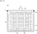
- FIG. 2 is a schematic diagram showing a battery module according to one exemplary embodiment of the present disclosure
- FIG. 3 is a side view of a battery module according to the one exemplary embodiment of the present disclosure.
- a battery module 100 according to the present disclosure includes: a battery cell stack 110 comprising n (n is an integer equal to or greater than 2) battery cells 111; a case 120 having one open end and accommodating the battery cell stack 110 inside thereof; an upper plate 130 laminated on an upper end of the battery cell stack 110; and a constant force spring 140 configured to be positioned inside the case 120 and be fixed on a lower portion of the case 120.
- the battery module 100 has a structure in which a compression pad 160 is formed at each of the upper end and the lower end of the battery cell stack 110 of the battery module, and the compression pad 160 is interposed between respective battery cell stacks. Further, the battery module 100 includes a case cover 121 configured to cover the one open end of the case 120.
- the constant force spring 140 is located at two or more spots which are symmetrical to each other with respect to a stacking surface. Specifically, the constant force spring 140 may be located at both sides of the battery cell stack 110 where the electrode lead has not been formed.
- the constant force spring 140 is a spring which has been wound in a spring form and includes a winding end 141 and a free end 142.
- the winding end 141 means a region which has been wound in a constant force spring
- the free end 142 means an opposite region of the winding end 141.
- winding end 141 of the constant force spring 140 is fixed at the lower portion of the case 120, and the free end 142 is fixed at the upper plate 130. Meanwhile, a holder or mounting portion for fixing a wound region of the constant force spring 140 may be included in the lower portion of the case 120.
- the winding end 141 has a spring form having an empty space in the center, and the holder or mounting portion may fix the constant force spring 140 by penetrating the central portion of the winding end 141.
- the free end 142 of the constant force spring 140 has a fixing hole 143 formed thereon, and a fixing pin (not shown), through which the fixing hole 143 penetrates, is formed at the side surface of the upper plate 130.
- the fixing hole 143 of the free end 142 may be coupled with and fixed at the fixing pin of the upper plate 130.
- the free end 142 of such a constant force spring 140 is fixed at the upper plate 130 in a state that is mounted on the mounting portion or the holder in the case 120.
- the constant force spring 140 applies elastic force to pull the battery cell stack 110 in the case toward the lower end of the case 120, thereby pressing the battery cells 111 by a designed load.
- FIG. 4 is a schematic diagram showing a battery module according to another exemplary embodiment of the present disclosure.
- a battery module 200 includes: a battery cell stack 210 comprising n (n is an integer equal to or greater than 2) battery cells 211; a case 220 having one open end and accommodating the battery cell stack 210 inside thereof; an upper plate 230 laminated on an upper end of the battery cell stack 210; and a constant force spring 240 configured to be positioned inside the case 220 and be fixed on a lower portion of the case 220.
- the battery module 200 has a structure in which a compression pad 260 is formed at each of the upper end and the lower end of the battery cell stack 210 of the battery module, and the compression pad 260 is interposed between respective battery cell stacks. Further, the battery module 200 includes a case cover 221 configured to cover the one open end of the case 220.
- the battery module 200 includes one or more stopper blocks 250 between the case cover 221 and the upper plate 230.
- FIG. 4 it is shown that two stopper blocks 250 are provided, but the present disclosure is not limited thereto.
- the stopper block 250 is configured to limit the movement in the upward direction of the upper plate 230 and is attached to the inner side of the case cover 221 and the upper portion of the upper plate 230.
- a swelling phenomenon of the battery cell 211 in the battery module 200 occurs by more than a designed load, the upper plate 230 moves in the upward direction as the wound region of the constant force spring is unwound. Meanwhile, there is a predetermined space between the case cover 221 and the upper plate 230. If the swelling displacement of the battery cell goes beyond the predetermined space, the movement in the upward direction of the upper plate 230 may be limited by the stopper block 250.
Landscapes
- Chemical & Material Sciences (AREA)
- Chemical Kinetics & Catalysis (AREA)
- Electrochemistry (AREA)
- General Chemical & Material Sciences (AREA)
- Engineering & Computer Science (AREA)
- Manufacturing & Machinery (AREA)
- Battery Mounting, Suspending (AREA)
- Connection Of Batteries Or Terminals (AREA)
Abstract
Description
- The present invention relates to a battery module including a constant force spring and a battery pack including the same.
- This application claims the benefit of priority based on
Korean Patent Application No. 10-2020-0089333, filed on July 20, 2020 - In recent years, as the price of energy sources increases due to the depletion of fossil fuels and the interest of environmental pollution is amplified, the demand for environmentally friendly alternative energy sources has become an indispensable factor for future life. As such, various researches on power generation technologies such as nuclear power, solar power, wind power, and tidal power have been continued, and electric power storage devices for more efficient use of such generated energy have also been attracting much attention.
- In particular, with the development of technology and demand for mobile devices, the demand for batteries as energy sources is rapidly increasing, and accordingly, a lot of researches on batteries capable of meeting various demands have been conducted.
- Typically, in terms of the shape of the battery, there is a high demand for a prismatic secondary battery and a pouch-type secondary battery that can be applied to products such as mobile phones with a small thickness. In terms of materials, there is a high demand for lithium secondary batteries such as lithium ion batteries and lithium ion polymer batteries having advantages such as high energy density, discharge voltage, and output stability.
- Such a secondary battery is formed in a structure such that an electrode assembly including a positive electrode, a negative electrode, and a separator disposed therebetween is built in a battery case, and positive and negative electrode tabs are welded to two electrode leads and are sealed to be exposed to the outside of the battery case. The electrode tab is electrically connected to the external device through contact with the external device, and the secondary battery supplies power to the external device through the electrode tab or receives power from the external device.
-
FIG. 1 is a cross-sectional view of a conventional battery module. As shown inFIG. 1 , the conventional battery module includes a battery cell stack inside a case. Meanwhile, gas may be generated inside the battery cell in the charge/discharge process, and a swelling phenomenon, in which the battery cell is expanded or shrunk, may repeatedly occur due to the generated gas. In particular, there was a problem that as the thickness of the battery cell increased by the repetition of charge/discharge of the battery cell, the case of the battery module was deformed. - As such, there is a need for a technology for preventing the deformation of the case by maintaining the swelling force according to the charge/discharge of the battery cell constant.
- The present disclosure has been devised to solve the problems of the prior art, and an object of the present disclosure is to provide a battery module including a constant force spring and a battery pack including the same.
- The present disclosure provides a battery module including a constant force spring. In one embodiment, a battery module according to the present disclosure includes: a battery cell stack comprising n battery cells; a case having one open end and accommodating the battery cell stack inside thereof; an upper plate stacked on an upper end of the battery cell stack; and a constant force spring configured to be positioned inside the case and be fixed on a lower portion of the case, wherein the n is an integer equal to or greater than 2. At this time, the constant force spring includes a winding end and a free end, and the winding end is fixed at a lower portion of the case, and the free end is fixed at the upper plate.
- In one example, the constant force spring is located at two or more spots which are symmetrical to each other with respect to a stacking surface.
- In one embodiment, the battery module according to the present disclosure includes a case cover configured to cover the one open end of the case.
- In another embodiment, one or more stopper blocks are provided between the cover and the upper plate, so as to limit movement of the upper plate in an upward direction.
- In further another embodiment, a compression pad is formed at each of the upper end and the lower end of the battery cell stack. Further, m (m is an integer equal to or greater than 2) battery cell stacks are provided, and a compression pad is interposed between respective battery cell stacks.
- Further, the battery cell stack further includes a bus bar assembly electrically connecting the n battery cells.
- In one embodiment, the case further includes a holder or a spring mounting portion for fixing a region where the constant force spring is wound in a spring form.
- At this time, the free end of the constant force spring has a fixing hole formed thereon, and
- A fixing pin, through which the fixing hole penetrates, may be formed at a side surface of the upper plate.
- Further, the present disclosure provides a battery pack including the above-described battery module.
- According to a battery module including a constant force spring, and a battery pack including the same of the present disclosure, by including a constant force spring, even if a swelling phenomenon occurs in battery cells accommodated in a battery module, the surface pressure of the battery cells can be maintained constant.
-
-
FIG. 1 is a cross-sectional view of a conventional battery module. -
FIG. 2 is a schematic diagram showing a battery module according to one embodiment of the present disclosure. -
FIG. 3 is a side view of a battery module according to one embodiment of the present disclosure. -
FIG. 4 is a schematic diagram showing a battery module according to another embodiment of the present disclosure. - Hereinafter, the present disclosure will be described in detail with reference to the drawings. The terms and words used in the present specification and claims should not be construed as limited to ordinary or dictionary terms and the inventor may properly define the concept of the terms in order to best describe its disclosure. The terms and words should be construed as meaning and concept consistent with the technical idea of the present disclosure.
- The present disclosure relates to a battery module, and more particularly, to a battery module including a constant force spring. In one embodiment, the battery module includes: a battery cell stack comprising n (n is an integer equal to or greater than 2) battery cells; a case having one open end and accommodating the battery cell stack inside thereof; an upper plate stacked on an upper end of the battery cell stack; and a constant force spring configured to be positioned inside the case and be fixed on a lower portion of the case, wherein the constant force spring includes a winding end and a free end, and wherein the winding end is fixed at a lower portion of the case, and the free end is fixed at the upper plate.
- Generally, gas may be generated inside the battery cell in the charge/discharge process, and as such, a swelling phenomenon, in which the battery cell is expanded or shrunk, may repeatedly occur. In particular, there was a problem that as the thickness of the battery cell increased by the repetition of charge/discharge of the battery cell, the case of the battery module was deformed. As such, the present disclosure provides a battery module including a constant force spring and a battery pack including the same. More specifically, the present disclosure provides a battery module capable of allowing an expansion displacement by a swelling phenomenon while compressing n battery cells, which are accommodated in a battery module, with a constant force using the constant force spring.
- In the present disclosure, the constant force spring is a spring which is wound in a spring type, and means a spring which is wound in a direction, in which a spring type spring pulls with tension, and is formed to be restored to its original state by elastic force when elastic force is released. Unlike a general spring, the load of the constant force spring does not linearly increase as the displacement increases, and the load of the constant force spring may be maintained constant even when the displacement increases at a certain load. Namely, in the battery module of the present disclosure, the constant force spring presses the battery cells accommodated in the case by a constant load. Even if a battery cell swelling phenomenon occurs in the battery cells, the surface pressure of the battery cells may be maintained constant.
- Through various and repeated experiments observations, the inventors of the present disclosure have found that by fastening the battery cell stack with the constant force spring, the surface pressure of the battery cells is maintained constant even when a swelling phenomenon occurs in the battery cells.
- In one embodiment, the constant force spring is a spring which is wound in a spring form, and includes a winding end and a free end. Herein, the winding end means a region which has been wound in a constant force spring, and the free end means an opposite region of the winding end. In a specific example, the winding end of the constant force spring is fixed at the lower portion of the case, and the free end is fixed at the upper plate. Meanwhile, a holder or mounting portion for fixing a wound region of the constant force spring may be included in the lower portion of the case. For example, the winding end has a spring form having an empty space in the center, and the holder or mounting portion may fix the constant force spring by penetrating the central portion of the winding end.
- Further, the free end of the constant force spring has a fixing hole, and a fixing pin, through which the fixing hole penetrates, is formed at the side surface of the upper plate. Namely, the fixing hole of the free end may be coupled with and fixed at the fixing pin of the upper plate.
- The free end of such a constant force spring is fixed at the upper plate in a state that is mounted on the mounting portion or the holder in the case. As such, the constant force spring applies elastic force to pull the battery cell stack in the case toward the lower end of the case, thereby pressing the battery cells by a designed load.
- Meanwhile, the constant force spring is located at two or more spots which are symmetrical to each other with respect to a stacking surface of the battery cell stack. In a specific example, the constant force spring may be located at both sides of the battery cell stack where the electrode lead has not been formed. If the constant force spring is not located at spots which are symmetrical to each other with respect to a stacking surface of the battery cell stack, when a swelling phenomenon of the battery cell occurs, problems such as case deformation may occur due to the tilt of the battery cell stack in one direction. For example, the constant force spring is located at both sides of the battery cell stack, and two or more constant force springs may be located at each side.
- In one example, the battery cell stack has a structure in which n (n is an integer equal to or greater than 2) battery cells are laminated. The number (n) of laminated battery cells may be changed depending on the number of battery cells which need electric connection or depending on the capacity of the battery module. For example, the number (n) of laminated battery cells of the battery cell stack is in a range of 2 to 100, 2 to 50, 2 to 10, or 3 to 7.
- On the other hand, if the battery cell is a secondary battery capable of charging and discharging, it is not particularly limited. In a specific example, each battery cell constituting the battery cell stack is a pouch type unit cell, and an electrode assembly of a positive electrode/separator/negative electrode structure is built in a laminate sheet exterior material in a manner that is connected to electrode leads formed outside the exterior material. The electrode leads may be drawn to the outside of the sheet and may be extended in the same or opposite direction to each other.
- Further, the battery cell stack further includes a bus bar assembly which electrically connects the n battery cells. In one example, the bus bar assembly includes a bus bar or an insulating bar, and respective battery cells are electrically connected by such bars. Meanwhile, the battery cell stack may electrically connect battery cells in series or in parallel according to the positions where the bus bar and the insulating bar are disposed in the bus bar assembly. The bus bar assembly may be a conventional bus bar assembly.
- In one embodiment, the battery module according to the present disclosure includes a case having a structure in which one side is opened. The case means a housing for accommodating a battery cell stack, and an accommodation space for accommodating a battery cell stack is included in the case. Meanwhile, when the battery cell stack is accommodated in a case, the battery cell stack may be accommodated such that the laminated surface of the battery cell stack may be parallel to the bottom surface of the case.
- Further, the battery module according to the present disclosure further includes a case cover which is coupled with one surface of the case and covers one surface of the case. For example, the case may be a conventional U-case used as a battery module, and the case cover may be welded with the U-case.
- In one embodiment, the battery module according to the present disclosure includes an upper plate. The upper plate is laminated on the upper portion of the battery cell stack and may limit the movement at the upper portion of the battery cell stack by fastening a constant force spring. The upper plate may be plate-shaped and may be made of an electrically insulating material.
- In one embodiment, the battery module according to the present disclosure has spaces at regular intervals between the upper plate and the cover. In a specific example, when the swelling phenomenon of the battery cells occurs by more than a designed load limit, the upper plate moves in an upward direction as the wound region of the constant force spring is unwound.
- At this time, if there is no space between the upper plate and the cover, the case may be deformed by upward movement of the upper plate. Hence, the space between the upper plate and the cover is necessary to prevent the case deformation.
- In another embodiment, the battery module according to the present disclosure may include one or more stopper blocks between the case cover and the upper plate. The stopper block limits the movement in the upward direction of the upper plate and is attached on the inner side of the case cover or the upper portion of the upper plate.
- The stopper block limits the movement in the upward direction of the upper plate and is attached on the inner side of the case cover or the upper portion of the upper plate.
- In a specific example, when the swelling phenomenon of the battery cells occurs by more than a designed load limit, the upper plate moves in an upward direction as the wound region of the constant force spring is unwound. Meanwhile, there is a predetermined space between the case cover and the upper plate. If the swelling displacement of the battery cell goes beyond the predetermined space, the movement in the upward direction of the upper plate may be limited by the stopper block. The stopper block may be made of any material if it is a material for limiting the movement of the upper plate. For example, it may be an insulating plastic.
- In further another embodiment, the upper plate includes a protrusion () of a predetermined height in an upward direction. In a specific example, the protrusion may be included in both ends of the upper plate, and a stopper block may be attached to the cover. At this time, the stopper block may be located to contact the inner surface of the protrusion. Namely, the protrusion is used to limit the movement of the upper plate in a horizontal direction.

- In one embodiment, the battery module according to the present disclosure includes a compression pad. In a specific example, a compression pad may be formed at each of the upper end and the lower end of battery cell stacks of the battery module according to the present disclosure.
- In another embodiment, m (m is an integer equal to or greater than 2) battery cell stacks are provided in the battery module according to the present disclosure, and a compression pad may be interposed between respective battery cell stacks. The compression pad may be made of a polyurethane series material, and when thickness is modified by the swelling phenomenon of the battery cell, the change in the battery cell by the external impact may be absorbed.
- Further, the present disclosure provides a battery pack including a battery module described above.
- In a specific example, the present disclosure provides a battery pack generated by combining one or two or more battery modules.
- The battery pack is applicable to various types of energy storage devices and power sources. For example, the energy storage device is an Energy Storage System (ESS) that stores a large amount of electrical energy. In addition, the power source is applicable to the power source of a moving means such as a vehicle. The vehicle refers to any type of vehicle which uses secondary batteries as its auxiliary power source or main power source. Specifically, the vehicle includes a hybrid (HEV), a plug-in hybrid (PHEV), or a pure electric car (BEV, EV), and the like.
- Hereinafter, the present disclosure will be described in more detail through drawings and examples. As the inventive concept allows for various changes and numerous embodiments, particular embodiments will be illustrated in the drawings and described in detail in the text. However, this is not intended to limit the present disclosure to the specific form disclosed, and it should be understood to include all changes, equivalents, and substitutes included in the spirit and scope of the present disclosure.
-
FIG. 2 is a schematic diagram showing a battery module according to one exemplary embodiment of the present disclosure, andFIG. 3 is a side view of a battery module according to the one exemplary embodiment of the present disclosure. Referring toFIGS. 2 and3 , abattery module 100 according to the present disclosure includes: abattery cell stack 110 comprising n (n is an integer equal to or greater than 2)battery cells 111; acase 120 having one open end and accommodating thebattery cell stack 110 inside thereof; anupper plate 130 laminated on an upper end of thebattery cell stack 110; and aconstant force spring 140 configured to be positioned inside thecase 120 and be fixed on a lower portion of thecase 120. - Further, the
battery module 100 according to one example of the present disclosure has a structure in which acompression pad 160 is formed at each of the upper end and the lower end of thebattery cell stack 110 of the battery module, and thecompression pad 160 is interposed between respective battery cell stacks. Further, thebattery module 100 includes acase cover 121 configured to cover the one open end of thecase 120. - Meanwhile, the
constant force spring 140 is located at two or more spots which are symmetrical to each other with respect to a stacking surface. Specifically, theconstant force spring 140 may be located at both sides of thebattery cell stack 110 where the electrode lead has not been formed. - Further, the
constant force spring 140 is a spring which has been wound in a spring form and includes a windingend 141 and afree end 142. Herein, the windingend 141 means a region which has been wound in a constant force spring, and thefree end 142 means an opposite region of the windingend 141. - Specifically, winding
end 141 of theconstant force spring 140 is fixed at the lower portion of thecase 120, and thefree end 142 is fixed at theupper plate 130. Meanwhile, a holder or mounting portion for fixing a wound region of theconstant force spring 140 may be included in the lower portion of thecase 120. For example, the windingend 141 has a spring form having an empty space in the center, and the holder or mounting portion may fix theconstant force spring 140 by penetrating the central portion of the windingend 141. - Further, the
free end 142 of theconstant force spring 140 has a fixinghole 143 formed thereon, and a fixing pin (not shown), through which thefixing hole 143 penetrates, is formed at the side surface of theupper plate 130. Namely, the fixinghole 143 of thefree end 142 may be coupled with and fixed at the fixing pin of theupper plate 130. - The
free end 142 of such aconstant force spring 140 is fixed at theupper plate 130 in a state that is mounted on the mounting portion or the holder in thecase 120. As such, theconstant force spring 140 applies elastic force to pull thebattery cell stack 110 in the case toward the lower end of thecase 120, thereby pressing thebattery cells 111 by a designed load. -
FIG. 4 is a schematic diagram showing a battery module according to another exemplary embodiment of the present disclosure. - Referring to
FIG. 4 , abattery module 200 according to the present disclosure includes: abattery cell stack 210 comprising n (n is an integer equal to or greater than 2)battery cells 211; acase 220 having one open end and accommodating thebattery cell stack 210 inside thereof; anupper plate 230 laminated on an upper end of thebattery cell stack 210; and aconstant force spring 240 configured to be positioned inside thecase 220 and be fixed on a lower portion of thecase 220. - Further, the
battery module 200 according to one example of the present disclosure has a structure in which acompression pad 260 is formed at each of the upper end and the lower end of thebattery cell stack 210 of the battery module, and thecompression pad 260 is interposed between respective battery cell stacks. Further, thebattery module 200 includes acase cover 221 configured to cover the one open end of thecase 220. - Further, the
battery module 200 according to the present disclosure includes one or more stopper blocks 250 between thecase cover 221 and theupper plate 230. InFIG. 4 , it is shown that twostopper blocks 250 are provided, but the present disclosure is not limited thereto. - The
stopper block 250 is configured to limit the movement in the upward direction of theupper plate 230 and is attached to the inner side of thecase cover 221 and the upper portion of theupper plate 230. - Specifically, a swelling phenomenon of the
battery cell 211 in thebattery module 200 occurs by more than a designed load, theupper plate 230 moves in the upward direction as the wound region of the constant force spring is unwound. Meanwhile, there is a predetermined space between thecase cover 221 and theupper plate 230. If the swelling displacement of the battery cell goes beyond the predetermined space, the movement in the upward direction of theupper plate 230 may be limited by thestopper block 250. - Although preferred examples of the present disclosure have been described with reference to drawings, it can be understood that those skilled in the art can make various modifications and changes to the present disclosure without departing from the spirit and scope of the disclosure as set forth in the claims below.
- Therefore, the technical scope of the present disclosure should not be limited to the contents described in the detailed description of the specification but should be defined by the claims.
-
- 1, 100: battery module
- 10, 110, 210: battery cell stack
- 11, 111, 211: battery cell
- 112, 212: bus bar assembly
- 12, 120, 220: case
- 16, 121, 221: cover
- 130, 230: upper plate
- 140, 240: constant force spring
- 141: winding end
- 142: free end
- 143: fixing hole
- 250: stopper block
- 160, 260: compression Pad
Claims (10)
- A battery module comprising:a battery cell stack comprising n battery cells;a case having one open end and accommodating the battery cell stack inside thereof;an upper plate stacked on an upper end of the battery cell stack; anda constant force spring positioned inside the case and fixed on a lower portion of the case,wherein the constant force spring includes a winding end and a free end,wherein the winding end is fixed at a lower portion of the case, and the free end is fixed at the upper plate, andwherein the n is an integer equal to or greater than 2.
- The battery module of claim 1, wherein the constant force spring is located at two or more spots which are symmetrical to each other with respect to a stacking surface of the battery cell stack.
- The battery module of claim 1, further comprising a case cover covering the one open end of the case.
- The battery module of claim 3, wherein one or more stopper blocks are provided between the case cover and the upper plate so as to limit movement of the upper plate in an upward direction.
- The battery module of claim 1, wherein a compression pad is formed at each of a lower end and an upper end of the battery cell stack.
- The battery module of claim 1, wherein m battery cell stacks are provided, wherein the m is an integer equal to or greater than 2, and
wherein a compression pad is formed between respective battery cell stacks. - The battery module of claim 1, wherein the battery cell stack further includes a bus bar assembly electrically connecting the n battery cells.
- The battery module of claim 1, wherein the case further includes a holder or a spring mounting portion for fixing a region where the constant force spring is wound in a spring form.
- The battery module of claim 1, wherein the free end of the constant force spring comprises a fixing hole formed thereon, and
wherein a fixing pin, which penetrates the fixing hole, is formed at a side surface of the upper plate. - A battery pack comprising the battery module according to claim 1.
Applications Claiming Priority (2)
| Application Number | Priority Date | Filing Date | Title |
|---|---|---|---|
| KR1020200089333A KR102773545B1 (en) | 2020-07-20 | 2020-07-20 | Battery module including constant force spring and battery pack including the same |
| PCT/KR2021/005514 WO2022019445A1 (en) | 2020-07-20 | 2021-04-30 | Battery module comprising constant-force spring, and battery pack comprising same |
Publications (3)
| Publication Number | Publication Date |
|---|---|
| EP4037078A1 true EP4037078A1 (en) | 2022-08-03 |
| EP4037078A4 EP4037078A4 (en) | 2023-05-10 |
| EP4037078B1 EP4037078B1 (en) | 2025-04-16 |
Family
ID=79729224
Family Applications (1)
| Application Number | Title | Priority Date | Filing Date |
|---|---|---|---|
| EP21846398.2A Active EP4037078B1 (en) | 2020-07-20 | 2021-04-30 | Battery module comprising constant-force spring, and battery pack comprising same |
Country Status (9)
| Country | Link |
|---|---|
| US (1) | US20220376349A1 (en) |
| EP (1) | EP4037078B1 (en) |
| JP (1) | JP7566288B2 (en) |
| KR (1) | KR102773545B1 (en) |
| CN (1) | CN114600305A (en) |
| ES (1) | ES3026463T3 (en) |
| HU (1) | HUE071260T2 (en) |
| PL (1) | PL4037078T3 (en) |
| WO (1) | WO2022019445A1 (en) |
Families Citing this family (3)
| Publication number | Priority date | Publication date | Assignee | Title |
|---|---|---|---|---|
| CN115377602A (en) * | 2022-09-15 | 2022-11-22 | 中创新航科技股份有限公司 | Energy storage battery box |
| KR102925813B1 (en) * | 2023-12-22 | 2026-02-10 | 주식회사 엘지에너지솔루션 | Compression pad, battery cell stack and battery module including the same |
| CN120728149A (en) * | 2025-08-22 | 2025-09-30 | 宁德时代新能源科技股份有限公司 | Battery devices and power-consuming devices |
Family Cites Families (18)
| Publication number | Priority date | Publication date | Assignee | Title |
|---|---|---|---|---|
| US825702A (en) * | 1905-04-24 | 1906-07-10 | Morgan Spring Company | Detachable hook for spring-beds. |
| JPH07122252A (en) * | 1993-10-25 | 1995-05-12 | Sony Corp | Battery pack |
| JP2001167745A (en) | 1999-12-08 | 2001-06-22 | Power System:Kk | Pressurized structure of cell stack structure |
| US7855024B2 (en) * | 2006-12-27 | 2010-12-21 | Proton Energy Systems, Inc. | Compartmentalized storage tank for electrochemical cell system |
| JP2010040295A (en) | 2008-08-04 | 2010-02-18 | Toyota Motor Corp | Battery device |
| US8157225B2 (en) * | 2009-08-03 | 2012-04-17 | Richard Earl Kephart | Monopod for camera |
| US9634295B2 (en) * | 2010-01-15 | 2017-04-25 | Pellion Technologies, Inc. | Expandable battery pack containment device for pouch battery cells |
| AT511669B1 (en) | 2011-06-30 | 2015-06-15 | Avl List Gmbh | RECHARGEABLE ELECTRIC BATTERY |
| US9281548B2 (en) * | 2013-03-14 | 2016-03-08 | GM Global Technology Operations LLC | Battery module for mitigating gas accumulation and methods thereof |
| KR101787634B1 (en) * | 2014-10-31 | 2017-10-18 | 주식회사 엘지화학 | End plate with reinforcing structure for swelling of battery cell and battery module having the same |
| WO2017068705A1 (en) * | 2015-10-22 | 2017-04-27 | 日産自動車株式会社 | Method for assembling assembled battery, and assembled battery |
| DE102016201605A1 (en) * | 2016-02-03 | 2017-08-03 | Robert Bosch Gmbh | Battery module with a plurality of battery cells, method for its production and battery |
| US10784477B2 (en) * | 2016-11-28 | 2020-09-22 | Viking Power Systems Pte. Ltd. | Rechargeable battery with elastically compliant housing |
| JP6885791B2 (en) * | 2017-06-05 | 2021-06-16 | 積水化学工業株式会社 | Thermal runaway prevention sheet |
| KR102229410B1 (en) * | 2017-09-18 | 2021-03-17 | 주식회사 엘지화학 | Battery module and battery pack including the same |
| IL257010B (en) | 2018-01-18 | 2021-10-31 | Israel Aerospace Ind Ltd | Camera-based automatic aircraft control for radar operation |
| KR102506446B1 (en) | 2018-03-07 | 2023-03-06 | 삼성전자주식회사 | Battery housing structure and battery apparatus adopting the same |
| WO2020018618A1 (en) * | 2018-07-18 | 2020-01-23 | Gopro, Inc. | Apparatus for battery cooling considering battery expansion |
-
2020
- 2020-07-20 KR KR1020200089333A patent/KR102773545B1/en active Active
-
2021
- 2021-04-30 US US17/770,966 patent/US20220376349A1/en active Pending
- 2021-04-30 PL PL21846398.2T patent/PL4037078T3/en unknown
- 2021-04-30 HU HUE21846398A patent/HUE071260T2/en unknown
- 2021-04-30 EP EP21846398.2A patent/EP4037078B1/en active Active
- 2021-04-30 ES ES21846398T patent/ES3026463T3/en active Active
- 2021-04-30 JP JP2022524683A patent/JP7566288B2/en active Active
- 2021-04-30 CN CN202180006129.1A patent/CN114600305A/en active Pending
- 2021-04-30 WO PCT/KR2021/005514 patent/WO2022019445A1/en not_active Ceased
Also Published As
| Publication number | Publication date |
|---|---|
| KR20220010796A (en) | 2022-01-27 |
| JP2022554001A (en) | 2022-12-27 |
| KR102773545B1 (en) | 2025-02-27 |
| CN114600305A (en) | 2022-06-07 |
| WO2022019445A1 (en) | 2022-01-27 |
| EP4037078B1 (en) | 2025-04-16 |
| HUE071260T2 (en) | 2025-08-28 |
| JP7566288B2 (en) | 2024-10-15 |
| ES3026463T3 (en) | 2025-06-11 |
| EP4037078A4 (en) | 2023-05-10 |
| PL4037078T3 (en) | 2025-07-21 |
| US20220376349A1 (en) | 2022-11-24 |
Similar Documents
| Publication | Publication Date | Title |
|---|---|---|
| AU2019344239B2 (en) | Battery module and battery pack comprising battery module | |
| US11121395B2 (en) | Battery module with movable end plate responsive to cell swelling and battery pack including same | |
| EP3675239B1 (en) | Battery module, and battery pack and automobile comprising same | |
| CN108140763B (en) | Battery modules, battery packs including battery modules, and vehicles including battery packs | |
| DK2779269T3 (en) | The battery cell having a novel structure | |
| EP4037079A1 (en) | Battery module, battery module system, and battery pack comprising battery module | |
| KR20170135597A (en) | Battery module, battery pack comprising the battery module and vehicle comprising the battery pack | |
| US12322816B2 (en) | Battery module, battery rack comprising same battery module, and power storage device | |
| EP4037078B1 (en) | Battery module comprising constant-force spring, and battery pack comprising same | |
| EP2416399A1 (en) | Secondary battery and battery system | |
| EP3582286A1 (en) | Battery cell frame and battery module comprising same | |
| EP4207452B1 (en) | Battery module, battery pack including battery module, and vehicle including battery pack | |
| EP3907811B1 (en) | Battery module and battery pack including the same | |
| CN120810122B (en) | Battery device and electric equipment | |
| US20260051617A1 (en) | Battery cell, battery, and electric apparatus | |
| EP4138189A1 (en) | Secondary battery module and method for manufacturing same | |
| US12255357B2 (en) | Battery cell having asymmetric electrode leads, and battery module comprising same and having reinforced mechanical strength | |
| WO2013094168A1 (en) | Secondary battery | |
| KR20190008654A (en) | Battery Pack | |
| KR20230164556A (en) | Battery module and manufacturing method of the same | |
| CN120709594A (en) | Battery pack and power-consuming device | |
| KR20220056104A (en) | Battery cell and manufacturing method thereof |
Legal Events
| Date | Code | Title | Description |
|---|---|---|---|
| STAA | Information on the status of an ep patent application or granted ep patent |
Free format text: STATUS: THE INTERNATIONAL PUBLICATION HAS BEEN MADE |
|
| PUAI | Public reference made under article 153(3) epc to a published international application that has entered the european phase |
Free format text: ORIGINAL CODE: 0009012 |
|
| STAA | Information on the status of an ep patent application or granted ep patent |
Free format text: STATUS: REQUEST FOR EXAMINATION WAS MADE |
|
| 17P | Request for examination filed |
Effective date: 20220429 |
|
| AK | Designated contracting states |
Kind code of ref document: A1 Designated state(s): AL AT BE BG CH CY CZ DE DK EE ES FI FR GB GR HR HU IE IS IT LI LT LU LV MC MK MT NL NO PL PT RO RS SE SI SK SM TR |
|
| REG | Reference to a national code |
Ref country code: DE Ref legal event code: R079 Free format text: PREVIOUS MAIN CLASS: H01M0050200000 Ipc: H01M0050209000 Ref document number: 602021029363 Country of ref document: DE |
|
| A4 | Supplementary search report drawn up and despatched |
Effective date: 20230412 |
|
| RIC1 | Information provided on ipc code assigned before grant |
Ipc: H01M 10/04 20060101ALI20230404BHEP Ipc: H01M 50/242 20210101ALI20230404BHEP Ipc: H01M 50/209 20210101AFI20230404BHEP |
|
| DAV | Request for validation of the european patent (deleted) | ||
| DAX | Request for extension of the european patent (deleted) | ||
| GRAP | Despatch of communication of intention to grant a patent |
Free format text: ORIGINAL CODE: EPIDOSNIGR1 |
|
| STAA | Information on the status of an ep patent application or granted ep patent |
Free format text: STATUS: GRANT OF PATENT IS INTENDED |
|
| INTG | Intention to grant announced |
Effective date: 20250124 |
|
| GRAS | Grant fee paid |
Free format text: ORIGINAL CODE: EPIDOSNIGR3 |
|
| P01 | Opt-out of the competence of the unified patent court (upc) registered |
Free format text: CASE NUMBER: APP_6054/2025 Effective date: 20250205 |
|
| GRAA | (expected) grant |
Free format text: ORIGINAL CODE: 0009210 |
|
| STAA | Information on the status of an ep patent application or granted ep patent |
Free format text: STATUS: THE PATENT HAS BEEN GRANTED |
|
| AK | Designated contracting states |
Kind code of ref document: B1 Designated state(s): AL AT BE BG CH CY CZ DE DK EE ES FI FR GB GR HR HU IE IS IT LI LT LU LV MC MK MT NL NO PL PT RO RS SE SI SK SM TR |
|
| REG | Reference to a national code |
Ref country code: GB Ref legal event code: FG4D |
|
| REG | Reference to a national code |
Ref country code: CH Ref legal event code: EP Ref country code: DE Ref legal event code: R096 Ref document number: 602021029363 Country of ref document: DE |
|
| REG | Reference to a national code |
Ref country code: IE Ref legal event code: FG4D |
|
| REG | Reference to a national code |
Ref country code: SE Ref legal event code: TRGR |
|
| REG | Reference to a national code |
Ref country code: ES Ref legal event code: FG2A Ref document number: 3026463 Country of ref document: ES Kind code of ref document: T3 Effective date: 20250611 |
|
| PGFP | Annual fee paid to national office [announced via postgrant information from national office to epo] |
Ref country code: DE Payment date: 20250422 Year of fee payment: 5 |
|
| PGFP | Annual fee paid to national office [announced via postgrant information from national office to epo] |
Ref country code: ES Payment date: 20250516 Year of fee payment: 5 |
|
| PGFP | Annual fee paid to national office [announced via postgrant information from national office to epo] |
Ref country code: HU Payment date: 20250623 Year of fee payment: 5 |
|
| REG | Reference to a national code |
Ref country code: NL Ref legal event code: MP Effective date: 20250416 |
|
| REG | Reference to a national code |
Ref country code: HU Ref legal event code: AG4A Ref document number: E071260 Country of ref document: HU |
|
| PG25 | Lapsed in a contracting state [announced via postgrant information from national office to epo] |
Ref country code: NL Free format text: LAPSE BECAUSE OF FAILURE TO SUBMIT A TRANSLATION OF THE DESCRIPTION OR TO PAY THE FEE WITHIN THE PRESCRIBED TIME-LIMIT Effective date: 20250416 |
|
| REG | Reference to a national code |
Ref country code: AT Ref legal event code: MK05 Ref document number: 1786439 Country of ref document: AT Kind code of ref document: T Effective date: 20250416 |
|
| PG25 | Lapsed in a contracting state [announced via postgrant information from national office to epo] |
Ref country code: PT Free format text: LAPSE BECAUSE OF FAILURE TO SUBMIT A TRANSLATION OF THE DESCRIPTION OR TO PAY THE FEE WITHIN THE PRESCRIBED TIME-LIMIT Effective date: 20250818 Ref country code: FI Free format text: LAPSE BECAUSE OF FAILURE TO SUBMIT A TRANSLATION OF THE DESCRIPTION OR TO PAY THE FEE WITHIN THE PRESCRIBED TIME-LIMIT Effective date: 20250416 |
|
| REG | Reference to a national code |
Ref country code: LT Ref legal event code: MG9D |
|
| PG25 | Lapsed in a contracting state [announced via postgrant information from national office to epo] |
Ref country code: GR Free format text: LAPSE BECAUSE OF FAILURE TO SUBMIT A TRANSLATION OF THE DESCRIPTION OR TO PAY THE FEE WITHIN THE PRESCRIBED TIME-LIMIT Effective date: 20250717 Ref country code: NO Free format text: LAPSE BECAUSE OF FAILURE TO SUBMIT A TRANSLATION OF THE DESCRIPTION OR TO PAY THE FEE WITHIN THE PRESCRIBED TIME-LIMIT Effective date: 20250716 |
|
| PG25 | Lapsed in a contracting state [announced via postgrant information from national office to epo] |
Ref country code: BG Free format text: LAPSE BECAUSE OF FAILURE TO SUBMIT A TRANSLATION OF THE DESCRIPTION OR TO PAY THE FEE WITHIN THE PRESCRIBED TIME-LIMIT Effective date: 20250416 |
|
| PG25 | Lapsed in a contracting state [announced via postgrant information from national office to epo] |
Ref country code: HR Free format text: LAPSE BECAUSE OF FAILURE TO SUBMIT A TRANSLATION OF THE DESCRIPTION OR TO PAY THE FEE WITHIN THE PRESCRIBED TIME-LIMIT Effective date: 20250416 |
|
| PG25 | Lapsed in a contracting state [announced via postgrant information from national office to epo] |
Ref country code: AT Free format text: LAPSE BECAUSE OF FAILURE TO SUBMIT A TRANSLATION OF THE DESCRIPTION OR TO PAY THE FEE WITHIN THE PRESCRIBED TIME-LIMIT Effective date: 20250416 |
|
| PG25 | Lapsed in a contracting state [announced via postgrant information from national office to epo] |
Ref country code: RS Free format text: LAPSE BECAUSE OF FAILURE TO SUBMIT A TRANSLATION OF THE DESCRIPTION OR TO PAY THE FEE WITHIN THE PRESCRIBED TIME-LIMIT Effective date: 20250716 |
|
| PG25 | Lapsed in a contracting state [announced via postgrant information from national office to epo] |
Ref country code: IS Free format text: LAPSE BECAUSE OF FAILURE TO SUBMIT A TRANSLATION OF THE DESCRIPTION OR TO PAY THE FEE WITHIN THE PRESCRIBED TIME-LIMIT Effective date: 20250816 |
|
| PG25 | Lapsed in a contracting state [announced via postgrant information from national office to epo] |
Ref country code: LV Free format text: LAPSE BECAUSE OF FAILURE TO SUBMIT A TRANSLATION OF THE DESCRIPTION OR TO PAY THE FEE WITHIN THE PRESCRIBED TIME-LIMIT Effective date: 20250416 |
|
| REG | Reference to a national code |
Ref country code: CH Ref legal event code: H13 Free format text: ST27 STATUS EVENT CODE: U-0-0-H10-H13 (AS PROVIDED BY THE NATIONAL OFFICE) Effective date: 20251125 |
|
| PG25 | Lapsed in a contracting state [announced via postgrant information from national office to epo] |
Ref country code: LU Free format text: LAPSE BECAUSE OF NON-PAYMENT OF DUE FEES Effective date: 20250430 |
|
| PG25 | Lapsed in a contracting state [announced via postgrant information from national office to epo] |
Ref country code: SM Free format text: LAPSE BECAUSE OF FAILURE TO SUBMIT A TRANSLATION OF THE DESCRIPTION OR TO PAY THE FEE WITHIN THE PRESCRIBED TIME-LIMIT Effective date: 20250416 Ref country code: DK Free format text: LAPSE BECAUSE OF FAILURE TO SUBMIT A TRANSLATION OF THE DESCRIPTION OR TO PAY THE FEE WITHIN THE PRESCRIBED TIME-LIMIT Effective date: 20250416 |
|
| PG25 | Lapsed in a contracting state [announced via postgrant information from national office to epo] |
Ref country code: CH Free format text: LAPSE BECAUSE OF NON-PAYMENT OF DUE FEES Effective date: 20250430 |
|
| REG | Reference to a national code |
Ref country code: DE Ref legal event code: R097 Ref document number: 602021029363 Country of ref document: DE |
|
| PG25 | Lapsed in a contracting state [announced via postgrant information from national office to epo] |
Ref country code: CZ Free format text: LAPSE BECAUSE OF FAILURE TO SUBMIT A TRANSLATION OF THE DESCRIPTION OR TO PAY THE FEE WITHIN THE PRESCRIBED TIME-LIMIT Effective date: 20250416 |
|
| PG25 | Lapsed in a contracting state [announced via postgrant information from national office to epo] |
Ref country code: EE Free format text: LAPSE BECAUSE OF FAILURE TO SUBMIT A TRANSLATION OF THE DESCRIPTION OR TO PAY THE FEE WITHIN THE PRESCRIBED TIME-LIMIT Effective date: 20250416 |
|
| PG25 | Lapsed in a contracting state [announced via postgrant information from national office to epo] |
Ref country code: SK Free format text: LAPSE BECAUSE OF FAILURE TO SUBMIT A TRANSLATION OF THE DESCRIPTION OR TO PAY THE FEE WITHIN THE PRESCRIBED TIME-LIMIT Effective date: 20250416 |
|
| PG25 | Lapsed in a contracting state [announced via postgrant information from national office to epo] |
Ref country code: IT Free format text: LAPSE BECAUSE OF FAILURE TO SUBMIT A TRANSLATION OF THE DESCRIPTION OR TO PAY THE FEE WITHIN THE PRESCRIBED TIME-LIMIT Effective date: 20250416 |
|
| PG25 | Lapsed in a contracting state [announced via postgrant information from national office to epo] |
Ref country code: MC Free format text: LAPSE BECAUSE OF FAILURE TO SUBMIT A TRANSLATION OF THE DESCRIPTION OR TO PAY THE FEE WITHIN THE PRESCRIBED TIME-LIMIT Effective date: 20250416 |
|
| PG25 | Lapsed in a contracting state [announced via postgrant information from national office to epo] |
Ref country code: RO Free format text: LAPSE BECAUSE OF FAILURE TO SUBMIT A TRANSLATION OF THE DESCRIPTION OR TO PAY THE FEE WITHIN THE PRESCRIBED TIME-LIMIT Effective date: 20250416 |
|
| PLBE | No opposition filed within time limit |
Free format text: ORIGINAL CODE: 0009261 |
|
| STAA | Information on the status of an ep patent application or granted ep patent |
Free format text: STATUS: NO OPPOSITION FILED WITHIN TIME LIMIT |
|
| REG | Reference to a national code |
Ref country code: CH Ref legal event code: L10 Free format text: ST27 STATUS EVENT CODE: U-0-0-L10-L00 (AS PROVIDED BY THE NATIONAL OFFICE) Effective date: 20260225 |
|
| 26N | No opposition filed |
Effective date: 20260119 |
|
| PGFP | Annual fee paid to national office [announced via postgrant information from national office to epo] |
Ref country code: SE Payment date: 20260323 Year of fee payment: 6 |
|
| PGFP | Annual fee paid to national office [announced via postgrant information from national office to epo] |
Ref country code: GB Payment date: 20260324 Year of fee payment: 6 |
|
| PG25 | Lapsed in a contracting state [announced via postgrant information from national office to epo] |
Ref country code: IE Free format text: LAPSE BECAUSE OF NON-PAYMENT OF DUE FEES Effective date: 20250430 |
|
| PGFP | Annual fee paid to national office [announced via postgrant information from national office to epo] |
Ref country code: BE Payment date: 20260323 Year of fee payment: 6 |
|
| PGFP | Annual fee paid to national office [announced via postgrant information from national office to epo] |
Ref country code: FR Payment date: 20260323 Year of fee payment: 6 |
|
| PGFP | Annual fee paid to national office [announced via postgrant information from national office to epo] |
Ref country code: PL Payment date: 20260325 Year of fee payment: 6 |