EP4036856A1 - Updating of annotated points in a digital image - Google Patents
Updating of annotated points in a digital image Download PDFInfo
- Publication number
- EP4036856A1 EP4036856A1 EP21154728.6A EP21154728A EP4036856A1 EP 4036856 A1 EP4036856 A1 EP 4036856A1 EP 21154728 A EP21154728 A EP 21154728A EP 4036856 A1 EP4036856 A1 EP 4036856A1
- Authority
- EP
- European Patent Office
- Prior art keywords
- digital image
- keypoints
- camera
- movement
- annotated
- Prior art date
- Legal status (The legal status is an assumption and is not a legal conclusion. Google has not performed a legal analysis and makes no representation as to the accuracy of the status listed.)
- Granted
Links
Images



Classifications
-
- G—PHYSICS
- G06—COMPUTING OR CALCULATING; COUNTING
- G06T—IMAGE DATA PROCESSING OR GENERATION, IN GENERAL
- G06T7/00—Image analysis
- G06T7/20—Analysis of motion
- G06T7/246—Analysis of motion using feature-based methods, e.g. the tracking of corners or segments
-
- G—PHYSICS
- G06—COMPUTING OR CALCULATING; COUNTING
- G06V—IMAGE OR VIDEO RECOGNITION OR UNDERSTANDING
- G06V20/00—Scenes; Scene-specific elements
- G06V20/70—Labelling scene content, e.g. deriving syntactic or semantic representations
-
- G—PHYSICS
- G06—COMPUTING OR CALCULATING; COUNTING
- G06T—IMAGE DATA PROCESSING OR GENERATION, IN GENERAL
- G06T7/00—Image analysis
- G06T7/70—Determining position or orientation of objects or cameras
- G06T7/73—Determining position or orientation of objects or cameras using feature-based methods
-
- G—PHYSICS
- G06—COMPUTING OR CALCULATING; COUNTING
- G06T—IMAGE DATA PROCESSING OR GENERATION, IN GENERAL
- G06T11/00—Two-dimensional [2D] image generation
- G06T11/60—Creating or editing images; Combining images with text
-
- G—PHYSICS
- G06—COMPUTING OR CALCULATING; COUNTING
- G06T—IMAGE DATA PROCESSING OR GENERATION, IN GENERAL
- G06T7/00—Image analysis
- G06T7/20—Analysis of motion
- G06T7/246—Analysis of motion using feature-based methods, e.g. the tracking of corners or segments
- G06T7/248—Analysis of motion using feature-based methods, e.g. the tracking of corners or segments involving reference images or patches
-
- G—PHYSICS
- G06—COMPUTING OR CALCULATING; COUNTING
- G06V—IMAGE OR VIDEO RECOGNITION OR UNDERSTANDING
- G06V10/00—Arrangements for image or video recognition or understanding
- G06V10/40—Extraction of image or video features
- G06V10/46—Descriptors for shape, contour or point-related descriptors, e.g. scale invariant feature transform [SIFT] or bags of words [BoW]; Salient regional features
-
- G—PHYSICS
- G06—COMPUTING OR CALCULATING; COUNTING
- G06T—IMAGE DATA PROCESSING OR GENERATION, IN GENERAL
- G06T2207/00—Indexing scheme for image analysis or image enhancement
- G06T2207/20—Special algorithmic details
- G06T2207/20112—Image segmentation details
- G06T2207/20164—Salient point detection; Corner detection
-
- G—PHYSICS
- G06—COMPUTING OR CALCULATING; COUNTING
- G06T—IMAGE DATA PROCESSING OR GENERATION, IN GENERAL
- G06T2207/00—Indexing scheme for image analysis or image enhancement
- G06T2207/30—Subject of image; Context of image processing
- G06T2207/30232—Surveillance
-
- G—PHYSICS
- G06—COMPUTING OR CALCULATING; COUNTING
- G06T—IMAGE DATA PROCESSING OR GENERATION, IN GENERAL
- G06T2207/00—Indexing scheme for image analysis or image enhancement
- G06T2207/30—Subject of image; Context of image processing
- G06T2207/30244—Camera pose
Definitions
- Embodiments presented herein relate to a method, an image processing device, a computer program, and a computer program product for updating a coordinate of an annotated point in a digital image due to camera movement.
- surveillance cameras are video cameras used for the purpose of observing an area.
- Surveillance cameras are often connected to a recording device or a network, such as an internet protocol (IP) network.
- IP internet protocol
- images recorded by the surveillance cameras are monitored in real-time by a security guard or law enforcement officer.
- Cameras and other type of recording equipment used to be relatively expensive and required human personnel to monitor camera footage, but automated software has been developed for analysis of footage in terms of digital images captured by digital image video cameras.
- automated software can be configured for digital image analysis as well as organization of the thus captured digital video footage into a searchable database.
- a surveillance zone In some surveillance scenarios, there could be a need to capture a scene having a Field of View (FoV) including one or more regions for which privacy should be preserved. The image content of such one or more regions should thus be excluded from any recording in the video surveillance system.
- FoV Field of View
- a surveillance zone where a surveillance zone is defined there could be a need to capture a scene having a FoV that is wider than the surveillance zone. Since only image content from inside the surveillance zone need to be analyzed, any image content outside the surveillance zone should be excluded from any analysis in the video surveillance system (although the image content outside the surveillance zone does not need to be excluded from any recording in the video surveillance system).
- a region of interest can be defined as a portion of an image that is to be subjected to filtering or other type of operation.
- An ROI can thus be defined such that the one or more regions for which privacy should be preserved is filtered out.
- An ROI can be defined by a binary mask. The binary mask is of the same size as the image to be processed. In the binary mask, pixels that define the ROI are set to 1 whereas all other pixels are set to 0 (or vice versa, depending on the purpose of the binary mask; to include or exclude the image content inside the ROI).
- a virtual line extending between two end-points, and defining a virtual trip wire could by the video surveillance system be added in the scene for crossline detection; an alarm, or other type of indication, is to be issued whenever an object (such as a human being, vehicle, or other type of object) crosses the virtual line in the scene.
- an object such as a human being, vehicle, or other type of object
- One way to define the corner points of an ROI and/or the end-points of the virtual line is to use annotated points.
- Each annotated point has a coordinate which commonly is manually or semi-automatically set.
- the coordinates of the annotated points might suffer from camera drifting due to vibration, camera position drift, FoV orientation shift, temperature changes, mechanical aging, and so on. This might cause the corner points of the ROI and/or the end-points of the virtual line to change, thereby affecting the location of the privacy mask, which part of the surveillance zone that is actually under surveillance, and/or the location of the virtual line.
- the annotated points need to be manually relabelled.
- An object of embodiments herein is to address the above issues by providing a method, an image processing device, a computer program, and a computer program product for updating a coordinate of an annotated point in a digital image due to camera movement (where, as above, the camera movement is caused by any of: camera drifting due to vibration, camera position drift, FoV orientation shift, temperature changes, mechanical aging, camera replacement).
- a method for updating a coordinate of an annotated point in a digital image due to camera movement is performed by an image processing device.
- the method comprises obtaining a current digital image of a scene.
- the current digital image has been captured by a camera subsequent to movement of the camera relative the scene.
- the current digital image is associated with at least one annotated point.
- Each at least one annotated point has a respective coordinate in the current digital image.
- the method comprises identifying an amount of the movement by comparing position indicative information in the current digital image to position indicative information in a previous digital image of the scene.
- the previous digital image has been captured prior to movement of the camera.
- the method comprises updating the coordinate of each at least one annotated point in accordance with the identified amount of movement and a camera homography.
- an image processing device for updating a coordinate of an annotated point in a digital image due to camera movement.
- the image processing device comprises processing circuitry.
- the processing circuitry is configured to cause the image processing device to obtain a current digital image of a scene.
- the current digital image has been captured by a camera subsequent to movement of the camera relative the scene.
- the current digital image is associated with at least one annotated point.
- Each at least one annotated point has a respective coordinate in the current digital image.
- the processing circuitry is configured to cause the image processing device to identify an amount of the movement by comparing position indicative information in the current digital image to position indicative information in a previous digital image of the scene.
- the previous digital image has been captured prior to movement of the camera.
- the processing circuitry is configured to cause the image processing device to update the coordinate of each at least one annotated point in accordance with the identified amount of movement and a camera homography.
- the video surveillance system comprises a camera and an image processing device according to the second aspect.
- a computer program for updating a coordinate of an annotated point in a digital image due to camera movement comprising computer program code which, when run on an image processing device, causes the image processing device to perform a method according to the first aspect.
- a computer program product comprising a computer program according to the fourth aspect and a computer readable storage medium on which the computer program is stored.
- the computer readable storage medium could be a non-transitory computer readable storage medium.
- these aspects provide accurate updating of the coordinate of the annotated point in the digital image due to camera movement.
- these aspects enable automatic re-location, or recalibration, of annotated points when they shift due to camera movement.
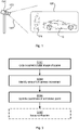
- Fig. 1 is a schematic diagram illustrating a scenario where embodiments presented herein can be applied.
- the schematic diagram of Fig. 1 represents a surveillance scenario.
- a camera 130 is configured to capture digital images, within a FoV 140, of a scene 100.
- the scene 100 comprises a vehicle 110 and a person 120.
- the camera 130 comprises an image processing device 150.
- the camera 130 and the image processing device 150 might be part of a video surveillance system. Such a video surveillance system could be applied to any of the above surveillance scenarios.
- the embodiments disclosed herein therefore relate to mechanisms for updating a coordinate of an annotated point in a digital image due to camera movement.
- an image processing device 150 a method performed by the image processing device 150, and a computer program product comprising code, for example in the form of a computer program, that when run on an image processing device 150, causes the image processing device 150 to perform the method.
- the embodiments disclosed herein enable feature-linked annotated points (of a previous digital image) to automatically calibrate the annotated points (of the current digital image) to solve the above issues relating to camera movement caused by any of camera drifting due to vibration, camera position drift, FoV orientation shift, temperature changes, mechanical aging, camera replacement.
- the embodiments disclosed herein are based on detecting movement of the camera 130 and updating at least one coordinate of an annotated points by comparing position indicative information of a current digital image to that of a previous digital image of the same scene 100. This will now be illustrated with reference to Fig. 2.
- FIG. 2 at (a) schematically illustrates annotated points a 1 , a 2 as well as position indicative information in terms of key points k 1 , k 2 , k 3 , k 4 , k 5 , k 6 in a previous digital image 200a.
- Fig. 2 at (b) schematically illustrates the same annotated points a 1 ⁇ , a 2 ⁇ and key points k 1 ⁇ , k 2 ⁇ , k 3 ⁇ , k 4 ⁇ , k 5 ⁇ , k 6 ⁇ as in the previous digital image 200a but in a current digital image 200b of the same scene as the previous digital image 200a.
- Fig. 2 at (b) schematically illustrates the same annotated points a 1 ⁇ , a 2 ⁇ and key points k 1 ⁇ , k 2 ⁇ , k 3 ⁇ , k 4 ⁇ , k 5 ⁇ , k 6 ⁇ as in the previous
- FIG. 2 is also marked at C the image center and a radius r extending from the image center C. Possible usage of the parameters C and r will be disclosed below. It is assumed that camera movement has occurred sometime in between capturing of the previous digital image 200a and capturing of the current digital image 200b. Therefore, as can be seen by comparing Fig. 2 at (b) to Fig. 2 at (a), the camera movement has caused the coordinates of the annotated points a 1 , a 2 (as well as the coordinates of the key points k 1 : k 6 ) to be shifted.
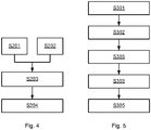
- Fig. 3 is a flowchart illustrating embodiments of methods for updating a coordinate of an annotated point a 1 , a 2 in a digital image 200b due to camera movement.
- the camera movement can be due to either one and the same camera 130 having been moved so that the FoV 140 changes, or that one camera 130 is replaced by another camera 130 (which, potentially, also causes the FoV 140 to change).
- the methods are performed by the image processing device 150.
- the methods are advantageously provided as computer programs 920.
- the image processing device 150 is configured to perform steps S102, S104, S106:
- This method enables automatic re-location, or recalibration, of annotated points when they shift due to camera movement.
- Embodiments relating to further details of updating a coordinate of an annotated point a 1 ⁇ , a 2 ⁇ in a digital image 200b due to camera movement as performed by the image processing device 150 will now be disclosed.
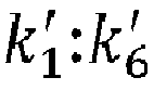
- the position indicative information in the current digital image 200b and the previous digital image 200a is defined by a respective set of keypoints k 1 :k 6 , k 1 ⁇ : k 6 ⁇ .
- the position indicative information in the current digital image 200b is represented by a first set of keypoints k 1 ⁇ : k 6 ⁇ extracted from the current digital image 200b
- the position indicative information in the previous digital image 200a is represented by a second set of keypoints k 1 : k 6 extracted from the previous digital image 200a.
- the comparing involves location-wise matching of the first set of keypoints k 1 ⁇ : k 6 ⁇ to the second set of keypoints k 1 : k 6 .
- the amount of movement is then identified from how much the coordinates in the current digital image 200b of the first set of keypoints k 1 : k 6 differ from the coordinates in the previous digital image 200a of the second set of keypoints k 1 :k 6 .
- the matching is performed by means of minimizing the distance between feature vectors in the current digital image 200b and feature vectors in the previous digital image 200a.
- a respective first feature vector is determined for each keypoint k 1 : k 6 in the first set of keypoints k 1 ⁇ : k 6 ⁇ and a respective second feature vector is determined for each keypoint k 1 : k 6 in the second set of keypoints k 1 :k 6 .
- the first set of keypoints k 1 ⁇ : k 6 ⁇ is then matched to the second set of keypoints k 1 : k 6 by finding a set of pairs of one of the first feature vectors and one of the second feature vectors that yields minimum distance between the first feature vectors and the second feature vectors among all sets of pairs of one of the first feature vectors and one of the second feature vectors.
- the second set of keypoints k 1 : k 6 is a subset of all keypoints k 1 : k 6 extractable from the previous digital image 200a. How selection of the most appropriate keypoints can be performed, in terms of how this subset of all keypoints k 1 : k 6 can be determined, will now be disclosed.
- any keypoints k 1 : k 6 with similar pairs of feature vectors are excluded from being included in the second set of keypoints k 1 :k 6 . That is, in some embodiments, those of all keypoints k 1 : k 6 with second feature vectors most similar to a second feature vector of another keypoint k 1 : k 6 extracted from the previous digital image 200a are excluded from being included in the second set of keypoints k 1 :k 6 .
- location information is used when determining which of all keypoints k 1 : k 6 to be included in the second set of keypoints k 1 :k 6 .
- which of all keypoints k 1 : k 6 to be included in the second set of keypoints k 1 : k 6 is dependent on their location in the previous digital image 200a. In this respect, as will be disclosed next, the location could be relative to the image center and/or the annotated points.
- those of all keypoints k 1 : k 6 located closest to the image center are candidates to be included in the second set of keypoints k 1 :k 6 .
- the second set of keypoints k 1 : k 6 is restricted to only include keypoints k 1 : k 6 located within a predefined radius, denoted r in Fig. 2 , from a center, denoted C in Fig. 2 , of the previous digital image 200a.
- those of all keypoints k 1 : k 6 located closest to the annotated points a 1 , a 2 are candidates to be included in the in the second set of keypoints k 1 :k 6 .
- the previous digital image 200a is associated with at least one annotated point a 1 , a 2 , where each at least one annotated point a 1 , a 2 has a respective coordinate in the previous digital image 200a, and the second set of keypoints k 1 : k 6 is restricted to only include keypoints k 1 : k 6 located within a predefined radius from the coordinate of the at least one annotated point a 1 , a 2 in the previous digital image 200a.
- the above embodiments, aspects, and examples enable the most appropriate keypoints to be selected according to the coordinate of the at least one annotated point, and the image centre.
- the previous digital image 200a is selected from a set of previous digital images 200a of the scene 100. Examples of how the previous digital image 200a can be selected from this set of previous digital images 200a of the scene 100 will now be disclosed.
- each of the previous digital images 200a in the set of previous digital images 200a has its own time stamp, and which previous digital image 200a to select is based on comparing the time stamps to a time stamp of the current digital image 200b.
- the previous digital image 200a can thus be selected based on a time stamp comparison such that the previous digital image 200a has been captured at the same time of day as the current digital image 200b, or closest in time to the current digital image 200b.
- previous digital image 200a to select is based on illumination, image quality, etc. Also combination of such parameters is envisioned. For example, in order to get the best image quality for optimizing the matching of the keypoints, the previous digital image 200a as well as the current digital image 200b can be extracted within a certain time interval, for example, during daytime. Further, similar time stamps could yield most similar image quality and illumination with respect to the previous digital image 200a and the current digital image 200b.
- the coordinate of each at least one annotated point a 1 , a 2 is updated by application of a homography matrix to the coordinate of each at least one annotated point a 1 ⁇ , a 2 ⁇ in the current digital image 200b.
- the homography matrix is dependent on the identified amount of movement and the camera homography.
- an alarm is triggered if the camera movement causes any annotated point a 1 ⁇ , a 2 ⁇ to move out from the image. That is, in some embodiments, the digital image processing device 150 is configured to perform (optional) step S108: S108: A notification is issued in case updating the coordinate of each at least one annotated point a 1 ⁇ , a 2 ⁇ causes any of the at least one annotated point a 1 ⁇ , a 2 ⁇ to have a coordinate outside the current digital image 200b.
- the herein disclosed embodiments can be described in two stages; a feature extraction stage and a calibration stage.
- the feature extraction stage involves the processing of the previous digital image whereas the calibration stage is applied after camera movement.
- S201 At least one annotated point is set in the digital image.
- Each such annotated point might represent a corner of an ROI or an end-point of a virtual line.
- the keypoints might be searched for using a keypoint detector.
- keypoint detectors are a Harris corner detector, a scale-invariant feature transform (SIFT) detector, and descriptors based on convolutional neural network (CNN).
- SIFT scale-invariant feature transform
- CNN convolutional neural network
- the keypoint detector identifies the coordinates of each keypoint as well as an associated descriptor (or feature vector). In some non-limiting examples the descriptor is provided as a 32 to 128 variable vector.
- the descriptors make each of the keypoints distinct and identifiable from the other keypoints. Without loss of generality, the total number of keypoints found is denoted K.
- Step S203 might be implemented in terms of a number of sub-steps, or sub-routines.
- M ⁇ K discriminative keypoints are selected by ranking their similarity.
- the similarity between a pair of two keypoints is computed from the Euclidean distance between the descriptors (or feature vectors) of the two keypoints. If the Euclidean distance is smaller than a pre-set threshold distance, this pair of keypoints are defined as similar, and therefore discarded.
- the M keypoints may be divided randomly into g subsets S g . Each such subset consists of N keypoints from the original M keypoints, where N « M . In some examples, at least 4 keypoints are selected, that is N ⁇ 4.
- d ( k i , a j ) is the Euclidean distance, in terms of coordinates, between each keypoint k i to each annotated point a j in the digital image
- d ( k i , C) is the Euclidean distance, in terms of coordinates, between each keypoint k i to the image center C
- w k and w c are their respective weights.
- J denotes the total number of annotated points.
- the weights can be used to either prioritize keypoints closer to the annotation points, or keypoints closer to the image center.
- the minimization criterion in (1) is used because the closer the distance, in terms of coordinates, between the keypoints and the annotation points in the digital image, the less the probability is for the keypoints to get lost, or even be moved out from the digital image, when the camera 130 is moved.
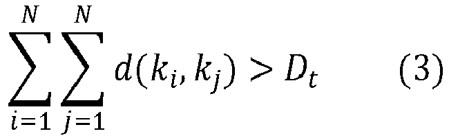
- the summation of distances d ( k i , k j ) between each two keypoints is larger than a threshold D t , which avoids the possibility of keypoints converging together.
- This can be implemented by different techniques, for example, the RANdom SAmple Consensus (RANSAC) algorithm.
- keypoints k 1 - k 4 have smaller distance, in terms of coordinates, to the annotated points and the image centre than keypoints k 5 and k 6 , and thus keypoints k 1 -k 4 are selected whilst keypoints k 5 and k 6 are discarded.
- the locations of the annotated points and the image centre are usually the most important positions.
- S204 The coordinates and descriptors (feature vectors) of the selected keypoints, as well as the coordinates of the annotated points, are stored.
- camera settings e.g. the camera focal length might be stored to enable calibration, or normalization, of the camera view, etc.
- S301 The coordinates of the annotated points and the keypoints (with their coordinates and descriptors) of a previous digital image of the same scene are obtained.
- the homography matrix is applied in order to account for camera movement, in terms of camera rotation and/or translation, between the previous digital image and the current digital image.
- the digital images are assumed to be normalized with respect to each other. Normalization can be achieved using information of the camera focal length used when the previous digital image was captured, and the camera focal length used when the current digital image was captured.
- the homography matrix H is computed from the matched annotated points by using Single Value Decomposition (SVD). Further aspects of how the homography matrix can be determined will be disclosed below.
- S305 The homography matrix is applied to the at least one annotated point in the current digital image.
- the homography matrix H can be reshaped from h. In order to improve homography matrix H, by minimizing the estimation error, a cost function could be applied.
- a ⁇ H ⁇ a
- Fig. 6 schematically illustrates a first scenario where the herein disclosed embodiments can be applied.
- a is illustrated a previous digital image 600a of a scene 610 as captured by a camera 130 of a video surveillance system.
- the scene comprises a building 620.
- the windows 630a:630f (not shown in Fig. 6(a) ) of the building are to be excluded from the surveillance.
- Six different privacy masks 640a:640f, each covering a window 630a:630f, are therefore applied.
- the lower-left corners of the privacy masks are defined by annotated points a 1 :a 6 .
- a current digital image 600b of the scene as captured by the camera 130 after camera movement.
- the camera movement causes the privacy masks to be moved, thus partly revealing the windows 630a:630f.
- the current digital image 600b' of the scene as captured by the camera 130 after camera movement upon application of at least some of the herein disclosed embodiments for updating the coordinates of the annotated points a 1 ⁇ : a 6 ⁇ in the current digital image due to the camera movement.
- the updating causes the privacy masks to be moved back to their correct positions, thus again properly covering the windows 630a:630f.
- Fig. 7 schematically illustrates a second scenario where the herein disclosed embodiments can be applied.
- a is illustrated a previous digital image 700a of a scene as captured by a camera 130 of a video surveillance system.
- the scene comprises buildings 710 and a parking lot 720.
- the parking lot defines a ROI 730 and is under surveillance.
- An ROI is therefore defined based on the corners of the parking lot.
- the corners of the ROI are defined by annotated points (represented by the single annotated point a 1 ).
- a current digital image 700b of the scene as captured by the camera 130 after camera movement.
- the camera movement causes the ROI 730 to be moved, thus partly excluding some parts of the parking lot 720 from surveillance.
- the current digital image 700b' of the scene as captured by the camera 130 after camera movement upon application of at least some of the herein disclosed embodiments for updating the coordinates of the annotated points (represented by the single annotated point a 1 ⁇ ) in the current digital image due to the camera movement.
- the updating causes the ROI 730 to be moved back to its correct position, thus again properly covering the parking lot 720.
- Fig. 8 schematically illustrates, in terms of a number of functional units, the components of an image processing device 150 according to an embodiment.
- Processing circuitry 810 is provided using any combination of one or more of a suitable central processing unit (CPU), multiprocessor, microcontroller, digital signal processor (DSP), etc., capable of executing software instructions stored in a computer program product 910 (as in Fig. 9 ), e.g. in the form of a storage medium 830.
- the processing circuitry 810 may further be provided as at least one application specific integrated circuit (ASIC), or field programmable gate array (FPGA).
- ASIC application specific integrated circuit
- FPGA field programmable gate array
- the processing circuitry 810 is configured to cause the image processing device 150 to perform a set of operations, or steps, as disclosed above.
- the storage medium 830 may store the set of operations
- the processing circuitry 810 may be configured to retrieve the set of operations from the storage medium 830 to cause the image processing device 150 to perform the set of operations.
- the set of operations may be provided as a set of executable instructions.
- the processing circuitry 810 is thereby arranged to execute methods as herein disclosed.
- the storage medium 830 may also comprise persistent storage, which, for example, can be any single one or combination of magnetic memory, optical memory, solid state memory or even remotely mounted memory.
- the image processing device 150 may further comprise a communications interface 820 at least configured for communications with the camera 130, potentially with other functions, nodes, entities and/or devices, such as functions, nodes, entities and/or devices of a video surveillance system.
- the communications interface 820 may comprise one or more transmitters and receivers, comprising analogue and digital components.
- the processing circuitry 810 controls the general operation of the image processing device 150, e.g., by sending data and control signals to the communications interface 820 and the storage medium 830, by receiving data and reports from the communications interface 820, and by retrieving data and instructions from the storage medium 830.
- Other components, as well as the related functionality, of the image processing device 150 are omitted in order not to obscure the concepts presented herein.
- the image processing device 150 may be provided as a standalone device or as a part of at least one further device.
- the image processing device 150 and the camera 130 might be part of a video surveillance system.
- a first portion of the instructions performed by the image processing device 150 may be executed in a first device, and a second portion of the of the instructions performed by the image processing device 150 may be executed in a second device; the herein disclosed embodiments are not limited to any particular number of devices on which the instructions performed by the image processing device 150 may be executed.
- the methods according to the herein disclosed embodiments are suitable to be performed by an image processing device 150 residing in a cloud computational environment. Therefore, although a single processing circuitry 810 is illustrated in Fig. 8 the processing circuitry 810 may be distributed among a plurality of devices, or nodes. The same applies to the computer program 920 of Fig. 9 .
- Fig. 9 shows one example of a computer program product 910 comprising computer readable storage medium 930.
- a computer program 920 can be stored, which computer program 920 can cause the processing circuitry 810 and thereto operatively coupled entities and devices, such as the communications interface 820 and the storage medium 830, to execute methods according to embodiments described herein.
- the computer program 920 and/or computer program product 910 may thus provide means for performing any steps as herein disclosed.
- the computer program product 910 is illustrated as an optical disc, such as a CD (compact disc) or a DVD (digital versatile disc) or a Blu-Ray disc.
- the computer program product 910 could also be embodied as a memory, such as a random access memory (RAM), a read-only memory (ROM), an erasable programmable read-only memory (EPROM), or an electrically erasable programmable read-only memory (EEPROM) and more particularly as a non-volatile storage medium of a device in an external memory such as a USB (Universal Serial Bus) memory or a Flash memory, such as a compact Flash memory.
- the computer program 920 is here schematically shown as a track on the depicted optical disk, the computer program 920 can be stored in any way which is suitable for the computer program product 910.
Landscapes
- Engineering & Computer Science (AREA)
- Physics & Mathematics (AREA)
- General Physics & Mathematics (AREA)
- Theoretical Computer Science (AREA)
- Multimedia (AREA)
- Computer Vision & Pattern Recognition (AREA)
- Computational Linguistics (AREA)
- Image Analysis (AREA)
Abstract
Description
- Embodiments presented herein relate to a method, an image processing device, a computer program, and a computer program product for updating a coordinate of an annotated point in a digital image due to camera movement.
- In general terms, surveillance cameras are video cameras used for the purpose of observing an area. Surveillance cameras are often connected to a recording device or a network, such as an internet protocol (IP) network. In some examples, images recorded by the surveillance cameras are monitored in real-time by a security guard or law enforcement officer. Cameras and other type of recording equipment used to be relatively expensive and required human personnel to monitor camera footage, but automated software has been developed for analysis of footage in terms of digital images captured by digital image video cameras. Such automated software can be configured for digital image analysis as well as organization of the thus captured digital video footage into a searchable database.
- In some surveillance scenarios, there could be a need to capture a scene having a Field of View (FoV) including one or more regions for which privacy should be preserved. The image content of such one or more regions should thus be excluded from any recording in the video surveillance system. In some surveillance scenarios, where a surveillance zone is defined there could be a need to capture a scene having a FoV that is wider than the surveillance zone. Since only image content from inside the surveillance zone need to be analyzed, any image content outside the surveillance zone should be excluded from any analysis in the video surveillance system (although the image content outside the surveillance zone does not need to be excluded from any recording in the video surveillance system). In respect to both these scenarios, a region of interest (ROI) can be defined as a portion of an image that is to be subjected to filtering or other type of operation. An ROI can thus be defined such that the one or more regions for which privacy should be preserved is filtered out. An ROI can be defined by a binary mask. The binary mask is of the same size as the image to be processed. In the binary mask, pixels that define the ROI are set to 1 whereas all other pixels are set to 0 (or vice versa, depending on the purpose of the binary mask; to include or exclude the image content inside the ROI).
- In other surveillance scenarios, a virtual line extending between two end-points, and defining a virtual trip wire, could by the video surveillance system be added in the scene for crossline detection; an alarm, or other type of indication, is to be issued whenever an object (such as a human being, vehicle, or other type of object) crosses the virtual line in the scene.
- One way to define the corner points of an ROI and/or the end-points of the virtual line is to use annotated points. Each annotated point has a coordinate which commonly is manually or semi-automatically set. However, once set, the coordinates of the annotated points might suffer from camera drifting due to vibration, camera position drift, FoV orientation shift, temperature changes, mechanical aging, and so on. This might cause the corner points of the ROI and/or the end-points of the virtual line to change, thereby affecting the location of the privacy mask, which part of the surveillance zone that is actually under surveillance, and/or the location of the virtual line. Further, when the camera is replaced, the annotated points need to be manually relabelled.
- Hence, there is a need for an improved handling of annotated points when a camera is subjected to camera movement (as, for example, caused by any of: camera drifting due to vibration, camera position drift, FoV orientation shift, temperature changes, mechanical aging, camera replacement).
- An object of embodiments herein is to address the above issues by providing a method, an image processing device, a computer program, and a computer program product for updating a coordinate of an annotated point in a digital image due to camera movement (where, as above, the camera movement is caused by any of: camera drifting due to vibration, camera position drift, FoV orientation shift, temperature changes, mechanical aging, camera replacement).
- According to a first aspect there is presented a method for updating a coordinate of an annotated point in a digital image due to camera movement. The method is performed by an image processing device. The method comprises obtaining a current digital image of a scene. The current digital image has been captured by a camera subsequent to movement of the camera relative the scene. The current digital image is associated with at least one annotated point. Each at least one annotated point has a respective coordinate in the current digital image. The method comprises identifying an amount of the movement by comparing position indicative information in the current digital image to position indicative information in a previous digital image of the scene. The previous digital image has been captured prior to movement of the camera. The method comprises updating the coordinate of each at least one annotated point in accordance with the identified amount of movement and a camera homography.
- According to a second aspect there is presented an image processing device for updating a coordinate of an annotated point in a digital image due to camera movement. The image processing device comprises processing circuitry. The processing circuitry is configured to cause the image processing device to obtain a current digital image of a scene. The current digital image has been captured by a camera subsequent to movement of the camera relative the scene. The current digital image is associated with at least one annotated point. Each at least one annotated point has a respective coordinate in the current digital image. The processing circuitry is configured to cause the image processing device to identify an amount of the movement by comparing position indicative information in the current digital image to position indicative information in a previous digital image of the scene. The previous digital image has been captured prior to movement of the camera. The processing circuitry is configured to cause the image processing device to update the coordinate of each at least one annotated point in accordance with the identified amount of movement and a camera homography.
- According to a third aspect there is presented a video surveillance system. The video surveillance system comprises a camera and an image processing device according to the second aspect.
- According to a fourth aspect there is presented a computer program for updating a coordinate of an annotated point in a digital image due to camera movement, the computer program comprising computer program code which, when run on an image processing device, causes the image processing device to perform a method according to the first aspect.
- According to a fifth aspect there is presented a computer program product comprising a computer program according to the fourth aspect and a computer readable storage medium on which the computer program is stored. The computer readable storage medium could be a non-transitory computer readable storage medium.
- Advantageously, these aspects resolve the issues noted above with respect to camera movement.
- Advantageously, these aspects provide accurate updating of the coordinate of the annotated point in the digital image due to camera movement.
- Advantageously, these aspects enable automatic re-location, or recalibration, of annotated points when they shift due to camera movement.
- Other objectives, features and advantages of the enclosed embodiments will be apparent from the following detailed disclosure, from the attached dependent claims as well as from the drawings.
- Generally, all terms used in the claims are to be interpreted according to their ordinary meaning in the technical field, unless explicitly defined otherwise herein. All references to "a/an/the element, apparatus, component, means, module, step, etc." are to be interpreted openly as referring to at least one instance of the element, apparatus, component, means, module, step, etc., unless explicitly stated otherwise. The steps of any method disclosed herein do not have to be performed in the exact order disclosed, unless explicitly stated.
- The inventive concept is now described, by way of example, with reference to the accompanying drawings, in which:
-
Fig. 1 is a schematic diagram illustrating a scenario according to embodiments; -
Fig. 2 schematically illustrates annotated points and position indicative information in digital images according to an embodiment; -
Fig. 3 ,Fig. 4, and Fig. 5 are flowcharts of methods according to embodiments; -
Fig. 6 andFig. 7 schematically illustrate example scenarios according to embodiments; -
Fig. 8 is a schematic diagram showing functional units of an image processing device according to an embodiment; and -
Fig. 9 shows one example of a computer program product comprising computer readable storage medium according to an embodiment. - The inventive concept will now be described more fully hereinafter with reference to the accompanying drawings, in which certain embodiments of the inventive concept are shown. This inventive concept may, however, be embodied in many different forms and should not be construed as limited to the embodiments set forth herein; rather, these embodiments are provided by way of example so that this disclosure will be thorough and complete, and will fully convey the scope of the inventive concept to those skilled in the art. Like numbers refer to like elements throughout the description. Any step or feature illustrated by dashed lines should be regarded as optional.
-
Fig. 1 is a schematic diagram illustrating a scenario where embodiments presented herein can be applied. The schematic diagram ofFig. 1 represents a surveillance scenario. Acamera 130 is configured to capture digital images, within aFoV 140, of ascene 100. In the illustrative example ofFig. 1 thescene 100 comprises avehicle 110 and aperson 120. Thecamera 130 comprises animage processing device 150. Thecamera 130 and theimage processing device 150 might be part of a video surveillance system. Such a video surveillance system could be applied to any of the above surveillance scenarios. - As noted above there is a need for an improved handling of annotated points when a
camera 130 is subjected to camera movement (as, for example, caused by any of:
camera drifting due to vibration, camera position drift, FoV orientation shift, temperature changes, mechanical aging, camera replacement). - The embodiments disclosed herein therefore relate to mechanisms for updating a coordinate of an annotated point in a digital image due to camera movement. In order to obtain such mechanisms there is provided an
image processing device 150, a method performed by theimage processing device 150, and a computer program product comprising code, for example in the form of a computer program, that when run on animage processing device 150, causes theimage processing device 150 to perform the method. - The embodiments disclosed herein enable feature-linked annotated points (of a previous digital image) to automatically calibrate the annotated points (of the current digital image) to solve the above issues relating to camera movement caused by any of camera drifting due to vibration, camera position drift, FoV orientation shift, temperature changes, mechanical aging, camera replacement. The embodiments disclosed herein are based on detecting movement of the
camera 130 and updating at least one coordinate of an annotated points by comparing position indicative information of a current digital image to that of a previous digital image of thesame scene 100. This will now be illustrated with reference toFig. 2. Fig. 2 at (a) schematically illustrates annotated points a 1, a 2 as well as position indicative information in terms of key points k 1 , k 2 , k 3 , k 4 , k 5 , k 6 in a previousdigital image 200a.Fig. 2 at (b) schematically illustrates the same annotated points


digital image 200a but in a currentdigital image 200b of the same scene as the previousdigital image 200a. InFig. 2 is also marked at C the image center and a radius r extending from the image center C. Possible usage of the parameters C and r will be disclosed below. It is assumed that camera movement has occurred sometime in between capturing of the previousdigital image 200a and capturing of the currentdigital image 200b. Therefore, as can be seen by comparingFig. 2 at (b) toFig. 2 at (a), the camera movement has caused the coordinates of the annotated points a 1, a 2 (as well as the coordinates of the key points k 1:k 6) to be shifted. -
Fig. 3 is a flowchart illustrating embodiments of methods for updating a coordinate of an annotated point a 1, a 2 in adigital image 200b due to camera movement. The camera movement can be due to either one and thesame camera 130 having been moved so that theFoV 140 changes, or that onecamera 130 is replaced by another camera 130 (which, potentially, also causes theFoV 140 to change). The methods are performed by theimage processing device 150. The methods are advantageously provided ascomputer programs 920. In particular, theimage processing device 150 is configured to perform steps S102, S104, S106: - S102: The
image processing device 150 obtains a currentdigital image 200b of ascene 100. The currentdigital image 200b has been captured by thecamera 130 subsequent to movement of thecamera 130 relative thescene 100. The currentdigital image 200b is associated with at least one annotated point


digital image 200b. - S104: The
image processing device 150 identifies the amount of the movement by comparing position indicative information in the currentdigital image 200b to position indicative information in a previousdigital image 200a of thescene 100. The previousdigital image 200a has been captured prior to movement of the camera 130 (either by thesame camera 130 or by another camera 130). - S106: The
image processing device 150 updates the coordinate of each at least one annotated point (from a 1, a 2 to

- This method enables automatic re-location, or recalibration, of annotated points when they shift due to camera movement.
- Embodiments relating to further details of updating a coordinate of an annotated point


digital image 200b due to camera movement as performed by theimage processing device 150 will now be disclosed. - There can be different examples of position indicative information. In some aspects, the position indicative information in the current
digital image 200b and the previousdigital image 200a is defined by a respective set of keypoints k 1 :k 6 ,
digital image 200b is represented by a first set of keypoints
digital image 200b, and the position indicative information in the previousdigital image 200a is represented by a second set of keypoints k 1:k 6 extracted from the previousdigital image 200a. - In some aspects, it is the matching between the keypoints

digital image 200b and the keypoints k 1:k 6 in the previousdigital image 200a that yields the amount of camera movement. In particular, in some embodiments, the comparing involves location-wise matching of the first set of keypoints
digital image 200b of the first set of keypoints k 1:k 6 differ from the coordinates in the previousdigital image 200a of the second set of keypoints k 1 :k 6 . - How discriminative keypoints can be selected based on ranking their similarity will be disclosed next. In some aspects, the matching is performed by means of minimizing the distance between feature vectors in the current
digital image 200b and feature vectors in the previousdigital image 200a. In particular, in some embodiments, a respective first feature vector is determined for each keypoint k 1:k 6 in the first set of keypoints
- Properties of the second set of keypoints k 1:k 6 will now be disclosed. In some embodiments, the second set of keypoints k 1:k 6 is a subset of all keypoints k 1:k 6 extractable from the previous
digital image 200a. How selection of the most appropriate keypoints can be performed, in terms of how this subset of all keypoints k 1:k 6 can be determined, will now be disclosed. - In some aspects, any keypoints k 1:k 6 with similar pairs of feature vectors are excluded from being included in the second set of keypoints k 1 :k 6 . That is, in some embodiments, those of all keypoints k 1:k 6 with second feature vectors most similar to a second feature vector of another keypoint k 1:k 6 extracted from the previous
digital image 200a are excluded from being included in the second set of keypoints k 1 :k 6 . - In some aspects, location information is used when determining which of all keypoints k 1:k 6 to be included in the second set of keypoints k 1 :k 6 . In particular, in some embodiments, which of all keypoints k 1:k 6 to be included in the second set of keypoints k 1:k 6 is dependent on their location in the previous
digital image 200a. In this respect, as will be disclosed next, the location could be relative to the image center and/or the annotated points. - In some aspects, those of all keypoints k 1:k 6 located closest to the image center are candidates to be included in the second set of keypoints k 1 :k 6 . In particular, in some embodiments, the second set of keypoints k 1:k 6 is restricted to only include keypoints k 1:k 6 located within a predefined radius, denoted r in
Fig. 2 , from a center, denoted C inFig. 2 , of the previousdigital image 200a. - In some aspects, those of all keypoints k 1:k 6 located closest to the annotated points a 1 , a 2 are candidates to be included in the in the second set of keypoints k 1 :k 6 . In particular, in some embodiments, the previous
digital image 200a is associated with at least one annotated point a 1 , a 2 , where each at least one annotated point a 1 , a 2 has a respective coordinate in the previousdigital image 200a, and the second set of keypoints k 1:k 6 is restricted to only include keypoints k 1:k 6 located within a predefined radius from the coordinate of the at least one annotated point a 1 , a 2 in the previousdigital image 200a. - Thereby, the above embodiments, aspects, and examples enable the most appropriate keypoints to be selected according to the coordinate of the at least one annotated point, and the image centre.
- In some aspects, the previous
digital image 200a is selected from a set of previousdigital images 200a of thescene 100. Examples of how the previousdigital image 200a can be selected from this set of previousdigital images 200a of thescene 100 will now be disclosed. - In some embodiments, each of the previous
digital images 200a in the set of previousdigital images 200a has its own time stamp, and which previousdigital image 200a to select is based on comparing the time stamps to a time stamp of the currentdigital image 200b. The previousdigital image 200a can thus be selected based on a time stamp comparison such that the previousdigital image 200a has been captured at the same time of day as the currentdigital image 200b, or closest in time to the currentdigital image 200b. - In further examples, which previous
digital image 200a to select is based on illumination, image quality, etc. Also combination of such parameters is envisioned. For example, in order to get the best image quality for optimizing the matching of the keypoints, the previousdigital image 200a as well as the currentdigital image 200b can be extracted within a certain time interval, for example, during daytime. Further, similar time stamps could yield most similar image quality and illumination with respect to the previousdigital image 200a and the currentdigital image 200b. - Aspects of how the coordinate of each at least one annotated point a 1 , a 2 can be updated will now be disclosed. In some embodiments, the coordinate of each at least one annotated point


digital image 200b. The homography matrix is dependent on the identified amount of movement and the camera homography. - Further aspects of further possible actions taken by the digital
image processing device 150 will now be disclosed. In some examples, an alarm is triggered if the camera movement causes any annotated point

image processing device 150 is configured to perform (optional) step S108:
S108: A notification is issued in case updating the coordinate of each at least one annotated point


digital image 200b. - Thereby, if a surveillance region of interest has moved out from the
FoV 140, then an alarm can be triggered. - In some aspects, the herein disclosed embodiments can be described in two stages; a feature extraction stage and a calibration stage. The feature extraction stage involves the processing of the previous digital image whereas the calibration stage is applied after camera movement.
- Aspects of the feature extraction stage will now be disclosed with reference to the flowchart of
Fig. 4 . - S201: At least one annotated point is set in the digital image.
- Each such annotated point might represent a corner of an ROI or an end-point of a virtual line.
- S202: Keypoints are searched for in the digital image.
- The keypoints might be searched for using a keypoint detector. Non-limiting examples of keypoint detectors are a Harris corner detector, a scale-invariant feature transform (SIFT) detector, and descriptors based on convolutional neural network (CNN). The keypoint detector identifies the coordinates of each keypoint as well as an associated descriptor (or feature vector). In some non-limiting examples the descriptor is provided as a 32 to 128 variable vector. The descriptors make each of the keypoints distinct and identifiable from the other keypoints. Without loss of generality, the total number of keypoints found is denoted K.
- S203: The most appropriate keypoints (descriptors) are selected.
- Step S203 might be implemented in terms of a number of sub-steps, or sub-routines.
- M ≤ K discriminative keypoints are selected by ranking their similarity. In one example, the similarity between a pair of two keypoints is computed from the Euclidean distance between the descriptors (or feature vectors) of the two keypoints. If the Euclidean distance is smaller than a pre-set threshold distance, this pair of keypoints are defined as similar, and therefore discarded.
- The M keypoints may be divided randomly into g subsets Sg. Each such subset consists of N keypoints from the original M keypoints, where N « M. In some examples, at least 4 keypoints are selected, that is N ≥ 4. The N keypoints are selected as having the minimum distances, in terms of coordinates, to the image centre and/or the annotated points, as defined by the minimization criterion in (1):


- In (2), d(ki, aj ) is the Euclidean distance, in terms of coordinates, between each keypoint ki to each annotated point aj in the digital image, and d(ki, C) is the Euclidean distance, in terms of coordinates, between each keypoint ki to the image center C, and wk and wc are their respective weights. Further, J denotes the total number of annotated points. The weights can be used to either prioritize keypoints closer to the annotation points, or keypoints closer to the image center. The minimization criterion in (1) is used because the closer the distance, in terms of coordinates, between the keypoints and the annotation points in the digital image, the less the probability is for the keypoints to get lost, or even be moved out from the digital image, when the
camera 130 is moved. - Further, the distance between each two keypoints ki, kj in each subset might fulfil:
- The summation of distances d(ki, kj ) between each two keypoints is larger than a threshold Dt, which avoids the possibility of keypoints converging together. This can be implemented by different techniques, for example, the RANdom SAmple Consensus (RANSAC) algorithm.
- For example, as illustrated in
Fig. 2 , keypoints k 1-k 4 have smaller distance, in terms of coordinates, to the annotated points and the image centre than keypoints k 5 and k 6, and thus keypoints k 1 -k 4 are selected whilst keypoints k 5 and k 6 are discarded. - In surveillance applications, the locations of the annotated points and the image centre are usually the most important positions.
- S204: The coordinates and descriptors (feature vectors) of the selected keypoints, as well as the coordinates of the annotated points, are stored.
- Also camera settings, e.g. the camera focal length might be stored to enable calibration, or normalization, of the camera view, etc.
- Aspects of the calibration stage (as applied after the
camera 130 has been moved or replaced) will now be disclosed with reference to the flowchart ofFig. 5 . - S301: The coordinates of the annotated points and the keypoints (with their coordinates and descriptors) of a previous digital image of the same scene are obtained.
- S302: Keypoints in the current image are identified. How to identify the keypoints in the current image has been disclosed above with reference to the description of
Fig. 3 . - S303: Matching keypoints are identified using feature vectors determined from the keypoints

digital image 200b and the keypoints k 1:k 6, in the previousdigital image 200a - S304: The homography matrix is determined from the matching keypoints.
- In this respect, the homography matrix is applied in order to account for camera movement, in terms of camera rotation and/or translation, between the previous digital image and the current digital image. The digital images are assumed to be normalized with respect to each other. Normalization can be achieved using information of the camera focal length used when the previous digital image was captured, and the camera focal length used when the current digital image was captured. In some non-limiting examples, the homography matrix H is computed from the matched annotated points by using Single Value Decomposition (SVD). Further aspects of how the homography matrix can be determined will be disclosed below.
- S305: The homography matrix is applied to the at least one annotated point in the current digital image.
- The updated coordinates, denoted A', of the at least one annotated point in the current digital image is then determined from the coordinates, denoted A, of the corresponding at least one annotated point in the previous digital image according to:

- Further aspects of how the homography matrix H can be determined will now be disclosed.
- Assume, without loss of generality, that there are four pairs of corresponding annotated points. Denote by a 1, a 2 , a 3 , a 4 the annotated points in the previous digital image and denote by


- First, determine the following 2-by-9 matrices:


- Expression (4) is thus equivalent to:

- Assume further that the matrix P has an SVD decomposition as follows:


- That is:

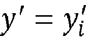
- The coordinates for annotated point pi' can thus be found by inserting x = xi, y = yi,

-
Fig. 6 schematically illustrates a first scenario where the herein disclosed embodiments can be applied. At (a) is illustrated a previousdigital image 600a of ascene 610 as captured by acamera 130 of a video surveillance system. The scene comprises abuilding 620. For privacy reasons, thewindows 630a:630f (not shown inFig. 6(a) ) of the building are to be excluded from the surveillance. Sixdifferent privacy masks 640a:640f, each covering awindow 630a:630f, are therefore applied. The lower-left corners of the privacy masks are defined by annotated points a 1 :a 6 . At (b) is illustrated a currentdigital image 600b of the scene as captured by thecamera 130 after camera movement. As noted at (b), since the annotated points a 1:a 6 have the same coordinates as in the previousdigital image 600a, the camera movement causes the privacy masks to be moved, thus partly revealing thewindows 630a:630f. At (c) is illustrated the currentdigital image 600b' of the scene as captured by thecamera 130 after camera movement upon application of at least some of the herein disclosed embodiments for updating the coordinates of the annotated points
windows 630a:630f. -
Fig. 7 schematically illustrates a second scenario where the herein disclosed embodiments can be applied. At (a) is illustrated a previousdigital image 700a of a scene as captured by acamera 130 of a video surveillance system. The scene comprises buildings 710 and aparking lot 720. The parking lot defines a ROI 730 and is under surveillance. An ROI is therefore defined based on the corners of the parking lot. The corners of the ROI are defined by annotated points (represented by the single annotated point a 1). At (b) is illustrated a currentdigital image 700b of the scene as captured by thecamera 130 after camera movement. As noted at (b), since the annotated points (again represented by the single annotated point a 1) have the same coordinates as in the previousdigital image 700a, the camera movement causes the ROI 730 to be moved, thus partly excluding some parts of theparking lot 720 from surveillance. At (c) is illustrated the currentdigital image 700b' of the scene as captured by thecamera 130 after camera movement upon application of at least some of the herein disclosed embodiments for updating the coordinates of the annotated points (represented by the single annotated point
parking lot 720. -
Fig. 8 schematically illustrates, in terms of a number of functional units, the components of animage processing device 150 according to an embodiment.Processing circuitry 810 is provided using any combination of one or more of a suitable central processing unit (CPU), multiprocessor, microcontroller, digital signal processor (DSP), etc., capable of executing software instructions stored in a computer program product 910 (as inFig. 9 ), e.g. in the form of astorage medium 830. Theprocessing circuitry 810 may further be provided as at least one application specific integrated circuit (ASIC), or field programmable gate array (FPGA). - Particularly, the
processing circuitry 810 is configured to cause theimage processing device 150 to perform a set of operations, or steps, as disclosed above. For example, thestorage medium 830 may store the set of operations, and theprocessing circuitry 810 may be configured to retrieve the set of operations from thestorage medium 830 to cause theimage processing device 150 to perform the set of operations. The set of operations may be provided as a set of executable instructions. - Thus, the
processing circuitry 810 is thereby arranged to execute methods as herein disclosed. Thestorage medium 830 may also comprise persistent storage, which, for example, can be any single one or combination of magnetic memory, optical memory, solid state memory or even remotely mounted memory. Theimage processing device 150 may further comprise acommunications interface 820 at least configured for communications with thecamera 130, potentially with other functions, nodes, entities and/or devices, such as functions, nodes, entities and/or devices of a video surveillance system. As such thecommunications interface 820 may comprise one or more transmitters and receivers, comprising analogue and digital components. Theprocessing circuitry 810 controls the general operation of theimage processing device 150, e.g., by sending data and control signals to thecommunications interface 820 and thestorage medium 830, by receiving data and reports from thecommunications interface 820, and by retrieving data and instructions from thestorage medium 830. Other components, as well as the related functionality, of theimage processing device 150 are omitted in order not to obscure the concepts presented herein. - The
image processing device 150 may be provided as a standalone device or as a part of at least one further device. For example, theimage processing device 150 and thecamera 130 might be part of a video surveillance system. - A first portion of the instructions performed by the
image processing device 150 may be executed in a first device, and a second portion of the of the instructions performed by theimage processing device 150 may be executed in a second device; the herein disclosed embodiments are not limited to any particular number of devices on which the instructions performed by theimage processing device 150 may be executed. Hence, the methods according to the herein disclosed embodiments are suitable to be performed by animage processing device 150 residing in a cloud computational environment. Therefore, although asingle processing circuitry 810 is illustrated inFig. 8 theprocessing circuitry 810 may be distributed among a plurality of devices, or nodes. The same applies to thecomputer program 920 ofFig. 9 . -
Fig. 9 shows one example of acomputer program product 910 comprising computerreadable storage medium 930. On this computerreadable storage medium 930, acomputer program 920 can be stored, whichcomputer program 920 can cause theprocessing circuitry 810 and thereto operatively coupled entities and devices, such as thecommunications interface 820 and thestorage medium 830, to execute methods according to embodiments described herein. Thecomputer program 920 and/orcomputer program product 910 may thus provide means for performing any steps as herein disclosed. - In the example of
Fig. 9 , thecomputer program product 910 is illustrated as an optical disc, such as a CD (compact disc) or a DVD (digital versatile disc) or a Blu-Ray disc. Thecomputer program product 910 could also be embodied as a memory, such as a random access memory (RAM), a read-only memory (ROM), an erasable programmable read-only memory (EPROM), or an electrically erasable programmable read-only memory (EEPROM) and more particularly as a non-volatile storage medium of a device in an external memory such as a USB (Universal Serial Bus) memory or a Flash memory, such as a compact Flash memory. Thus, while thecomputer program 920 is here schematically shown as a track on the depicted optical disk, thecomputer program 920 can be stored in any way which is suitable for thecomputer program product 910. - The inventive concept has mainly been described above with reference to a few embodiments. However, as is readily appreciated by a person skilled in the art, other embodiments than the ones disclosed above are equally possible within the scope of the inventive concept, as defined by the appended patent claims.
Claims (15)
- A method for updating a coordinate of an annotated point (

 obtaining (S102) a current digital image (200b) of a scene (100), the current digital image (200b) having been captured by a camera (130) subsequent to movement of the camera (130) relative the scene (100), wherein the current digital image (200b) is associated with at least one annotated point (


 identifying (S104) an amount of the movement by comparing position indicative information in the current digital image (200b) to position indicative information in a previous digital image (200a) of the scene (100), the previous digital image (200a) having been captured prior to movement of the camera (130); andupdating (S106) the coordinate of each at least one annotated point (

- The method according to claim 1, wherein the position indicative information in the current digital image (200b) is represented by a first set of keypoints (

- The method according to claim 2, wherein the comparing involves location-wise matching of the first set of keypoints (


- The method according to claim 2 or 3, wherein a respective first feature vector is determined for each keypoint (


- The method according to any of claims 2 to 4, wherein the second set of keypoints (k 1:k 6) is a subset of all keypoints (k 1:k 6) extractable from the previous digital image (200a).
- The method according to claim 5, wherein those of all keypoints (k 1:k 6) with second feature vectors most similar to a second feature vector of another keypoint (k 1:k 6) extracted from the previous digital image (200a) are excluded from being included in the second set of keypoints (k 1:k 6).
- The method according to claim 5 or 6, wherein which of all keypoints (k 1:k 6) to be included in the second set of keypoints (k 1:k 6) is dependent on their location in the previous digital image (200a).
- The method according to any of claims 5 to 7, wherein the second set of keypoints (k 1:k 6) is restricted to only include keypoints (k 1:k 6) located within a predefined radius (r) from a center (C) of the previous digital image (200a).
- The method according to any of claims 5 to 8, wherein the previous digital image (200a) is associated with at least one annotated point (a 1, a 2) having a respective coordinate in the previous digital image (200a), and wherein the second set of keypoints (k 1:k 6) is restricted to only include keypoints (k 1:k 6) located within a predefined radius from the coordinate of the at least one annotated point (a 1, a 2) in the previous digital image (200a).
- The method according to any preceding claim, wherein the previous digital image (200a) is selected from a set of previous digital images (200a) of the scene (100), wherein each of the previous digital images (200a) in the set of previous digital images (200a) has its own time stamp, and wherein which previous digital image (200a) to select is based on comparing the time stamps to a time stamp of the current digital image (200b).
- The method according to any preceding claim, wherein the coordinate of each at least one annotated point (


- The method according to any preceding claim, wherein the method further comprises:
issuing (S108) a notification in case updating the coordinate of each at least one annotated point (


- The method according to any preceding claim, wherein there are at least two annotated points (


- An image processing device (150) for updating a coordinate of an annotated point (

 obtain a current digital image (200b) of a scene (100), the current digital image (200b) having been captured by a camera (130) subsequent to movement of the camera (130) relative the scene (100), wherein the current digital image (200b) is associated with at least one annotated point (


 identify an amount of the movement by comparing position indicative information in the current digital image (200b) to position indicative information in a previous digital image (200a) of the scene (100), the previous digital image (200a) having been captured prior to movement of the camera (130); andupdate the coordinate of each at least one annotated point (

- A computer program (920) for updating a coordinate of an annotated point (

 obtain (S102) a current digital image (200b) of a scene (100), the current digital image (200b) having been captured by a camera (130) subsequent to movement of the camera (130) relative the scene (100), wherein the current digital image (200b) is associated with at least one annotated point (


 identify (S104) an amount of the movement by comparing position indicative information in the current digital image (200b) to position indicative information in a previous digital image (200a) of the scene (100), the previous digital image (200a) having been captured prior to movement of the camera (130); andupdate (S106) the coordinate of each at least one annotated point (

Priority Applications (3)
| Application Number | Priority Date | Filing Date | Title |
|---|---|---|---|
| EP21154728.6A EP4036856B1 (en) | 2021-02-02 | 2021-02-02 | Updating of annotated points in a digital image |
| US17/552,738 US11972622B2 (en) | 2021-02-02 | 2021-12-16 | Updating of annotated points in a digital image |
| CN202210020624.4A CN114842076A (en) | 2021-02-02 | 2022-01-10 | Updating annotation points in digital images |
Applications Claiming Priority (1)
| Application Number | Priority Date | Filing Date | Title |
|---|---|---|---|
| EP21154728.6A EP4036856B1 (en) | 2021-02-02 | 2021-02-02 | Updating of annotated points in a digital image |
Publications (3)
| Publication Number | Publication Date |
|---|---|
| EP4036856A1 true EP4036856A1 (en) | 2022-08-03 |
| EP4036856C0 EP4036856C0 (en) | 2025-04-30 |
| EP4036856B1 EP4036856B1 (en) | 2025-04-30 |
Family
ID=74572628
Family Applications (1)
| Application Number | Title | Priority Date | Filing Date |
|---|---|---|---|
| EP21154728.6A Active EP4036856B1 (en) | 2021-02-02 | 2021-02-02 | Updating of annotated points in a digital image |
Country Status (3)
| Country | Link |
|---|---|
| US (1) | US11972622B2 (en) |
| EP (1) | EP4036856B1 (en) |
| CN (1) | CN114842076A (en) |
Families Citing this family (1)
| Publication number | Priority date | Publication date | Assignee | Title |
|---|---|---|---|---|
| US12041378B2 (en) * | 2021-09-17 | 2024-07-16 | BCD International, Inc. | Combined security and video camera control system |
Citations (1)
| Publication number | Priority date | Publication date | Assignee | Title |
|---|---|---|---|---|
| US9646571B1 (en) * | 2013-06-04 | 2017-05-09 | Bentley Systems, Incorporated | Panoramic video augmented reality |
Family Cites Families (19)
| Publication number | Priority date | Publication date | Assignee | Title |
|---|---|---|---|---|
| JP4874280B2 (en) * | 2008-03-19 | 2012-02-15 | 三洋電機株式会社 | Image processing apparatus and method, driving support system, and vehicle |
| US20120294537A1 (en) | 2008-05-02 | 2012-11-22 | Eyeic, Inc. | System for using image alignment to map objects across disparate images |
| US9955056B2 (en) | 2015-03-16 | 2018-04-24 | Qualcomm Incorporated | Real time calibration for multi-camera wireless device |
| JP6573744B2 (en) * | 2017-03-06 | 2019-09-11 | 三菱電機株式会社 | Object tracking device and object tracking method |
| CN109584295B (en) * | 2017-09-29 | 2022-08-26 | 阿里巴巴集团控股有限公司 | Method, device and system for automatically labeling target object in image |
| CN108682036B (en) * | 2018-04-27 | 2022-10-25 | 腾讯科技(深圳)有限公司 | Pose determination method, pose determination device and storage medium |
| US10701336B2 (en) | 2018-08-24 | 2020-06-30 | Samsung Electronics Co., Ltd. | Rectifying a sequence of stereo images |
| US10778916B2 (en) * | 2018-10-24 | 2020-09-15 | Honeywell International Inc. | Applying an annotation to an image based on keypoints |
| CN110285793B (en) * | 2019-07-08 | 2020-05-15 | 中原工学院 | Intelligent vehicle track measuring method based on binocular stereo vision system |
| CN110335292B (en) * | 2019-07-09 | 2021-04-30 | 北京猫眼视觉科技有限公司 | Method, system and terminal for realizing simulation scene tracking based on picture tracking |
| CN110706251B (en) * | 2019-09-03 | 2022-09-23 | 北京正安维视科技股份有限公司 | Cross-lens tracking method for pedestrians |
| CN110569810B (en) * | 2019-09-11 | 2022-02-08 | 浙江大华技术股份有限公司 | Method and device for acquiring coordinate information, storage medium and electronic device |
| CN111126304B (en) * | 2019-12-25 | 2023-07-07 | 鲁东大学 | Augmented reality navigation method based on indoor natural scene image deep learning |
| CN111260555A (en) * | 2020-01-15 | 2020-06-09 | 东华大学 | Improved image splicing method based on SURF |
| CN111914049B (en) * | 2020-07-29 | 2025-02-28 | 北京天睿空间科技股份有限公司 | Mapping method between latitude and longitude coordinates and image coordinates |
| US12159359B2 (en) * | 2021-03-11 | 2024-12-03 | Quintar, Inc. | Use of multiple registrations for augmented reality system for viewing an event |
| US12243296B2 (en) * | 2021-07-06 | 2025-03-04 | Samsung Electronics Co., Ltd. | Method of determining visual interference using a weighted combination of CIS and DVS measurement |
| US20230068798A1 (en) * | 2021-09-02 | 2023-03-02 | Amazon Technologies, Inc. | Active speaker detection using image data |
| TWI817680B (en) * | 2021-12-21 | 2023-10-01 | 鴻海精密工業股份有限公司 | Image data augmentation method and device |
-
2021
- 2021-02-02 EP EP21154728.6A patent/EP4036856B1/en active Active
- 2021-12-16 US US17/552,738 patent/US11972622B2/en active Active
-
2022
- 2022-01-10 CN CN202210020624.4A patent/CN114842076A/en active Pending
Patent Citations (1)
| Publication number | Priority date | Publication date | Assignee | Title |
|---|---|---|---|---|
| US9646571B1 (en) * | 2013-06-04 | 2017-05-09 | Bentley Systems, Incorporated | Panoramic video augmented reality |
Non-Patent Citations (2)
| Title |
|---|
| ONG S K ET AL: "Tracking points using projective reconstruction for augmented reality", COMPUTER GRAPHICS AND INTERACTIVE TECHNIQUES IN AUSTRALASIA AND SOUTH EAST ASIA, ACM, 2 PENN PLAZA, SUITE 701 NEW YORK NY 10121-0701 USA, 29 November 2005 (2005-11-29), pages 421 - 424, XP058291539, ISBN: 978-1-59593-201-3, DOI: 10.1145/1101389.1101472 * |
| SATOSHI YONEMOTO: "A Video Annotation Tool Using Vision-based AR Technology", CYBERWORLDS (CW), 2012 INTERNATIONAL CONFERENCE ON, IEEE, 25 September 2012 (2012-09-25), pages 226 - 230, XP032265643, ISBN: 978-1-4673-2736-7, DOI: 10.1109/CW.2012.39 * |
Also Published As
| Publication number | Publication date |
|---|---|
| EP4036856C0 (en) | 2025-04-30 |
| CN114842076A (en) | 2022-08-02 |
| US11972622B2 (en) | 2024-04-30 |
| US20220254178A1 (en) | 2022-08-11 |
| EP4036856B1 (en) | 2025-04-30 |
Similar Documents
| Publication | Publication Date | Title |
|---|---|---|
| US9773322B2 (en) | Image processing apparatus and image processing method which learn dictionary | |
| CN113793365B (en) | Target tracking method, apparatus, computer equipment and readable storage medium | |
| CN109727275B (en) | Object detection method, device, system and computer readable storage medium | |
| US12175683B2 (en) | Crowd type classification system, crowd type classification method and storage medium for storing crowd type classification program | |
| US11074698B2 (en) | Object tracking device and object tracking method | |
| Dogra et al. | Smart video summarization using mealy machine-based trajectory modelling for surveillance applications | |
| EP3549332A1 (en) | Image processing device and method for producing in real-time a digital composite image from a sequence of digital images | |
| CN116740149A (en) | Camera tracking method, device and storage medium | |
| US10762372B2 (en) | Image processing apparatus and control method therefor | |
| CN111402192B (en) | Methods and devices for detecting manhole covers | |
| CN111462188A (en) | Camera movement detection method and system | |
| US11972622B2 (en) | Updating of annotated points in a digital image | |
| CN111401239A (en) | Video analysis method, device, system, equipment and storage medium | |
| KR20180122831A (en) | Objects detecting system, method and computer readable recording medium | |
| CN112132895B (en) | Image-based position determination method, electronic device, and storage medium | |
| CN110728249A (en) | Cross-camera identification method, device and system for target pedestrian | |
| CN110781710B (en) | A target object clustering method and device | |
| CN114170417A (en) | Target object identification method and device, computer equipment and storage medium | |
| JPWO2022079841A5 (en) | Group identification device, group identification method, and program | |
| CN115830364B (en) | Method for detecting the status of opening and closing devices, computer equipment and storage devices | |
| WO2020139071A1 (en) | System and method for detecting aggressive behaviour activity | |
| CN118587765B (en) | Effective data supervision method, system and electronic equipment based on digitalization | |
| Bruckner et al. | Geometric and probabilistic image dissimilarity measures for common field of view detection | |
| CN117615119A (en) | Method and device for detecting abnormality of monitoring lens and electronic equipment | |
| CN119251772A (en) | Property abnormality monitoring method, device, equipment, and storage medium |
Legal Events
| Date | Code | Title | Description |
|---|---|---|---|
| PUAI | Public reference made under article 153(3) epc to a published international application that has entered the european phase |
Free format text: ORIGINAL CODE: 0009012 |
|
| STAA | Information on the status of an ep patent application or granted ep patent |
Free format text: STATUS: REQUEST FOR EXAMINATION WAS MADE |
|
| 17P | Request for examination filed |
Effective date: 20211008 |
|
| AK | Designated contracting states |
Kind code of ref document: A1 Designated state(s): AL AT BE BG CH CY CZ DE DK EE ES FI FR GB GR HR HU IE IS IT LI LT LU LV MC MK MT NL NO PL PT RO RS SE SI SK SM TR |
|
| STAA | Information on the status of an ep patent application or granted ep patent |
Free format text: STATUS: EXAMINATION IS IN PROGRESS |
|
| 17Q | First examination report despatched |
Effective date: 20230602 |
|
| GRAP | Despatch of communication of intention to grant a patent |
Free format text: ORIGINAL CODE: EPIDOSNIGR1 |
|
| STAA | Information on the status of an ep patent application or granted ep patent |
Free format text: STATUS: GRANT OF PATENT IS INTENDED |
|
| GRAS | Grant fee paid |
Free format text: ORIGINAL CODE: EPIDOSNIGR3 |
|
| INTG | Intention to grant announced |
Effective date: 20250221 |
|
| GRAA | (expected) grant |
Free format text: ORIGINAL CODE: 0009210 |
|
| STAA | Information on the status of an ep patent application or granted ep patent |
Free format text: STATUS: THE PATENT HAS BEEN GRANTED |
|
| AK | Designated contracting states |
Kind code of ref document: B1 Designated state(s): AL AT BE BG CH CY CZ DE DK EE ES FI FR GB GR HR HU IE IS IT LI LT LU LV MC MK MT NL NO PL PT RO RS SE SI SK SM TR |
|
| REG | Reference to a national code |
Ref country code: CH Ref legal event code: EP Ref country code: GB Ref legal event code: FG4D |
|
| REG | Reference to a national code |
Ref country code: DE Ref legal event code: R096 Ref document number: 602021029843 Country of ref document: DE |
|
| REG | Reference to a national code |
Ref country code: IE Ref legal event code: FG4D |
|
| U01 | Request for unitary effect filed |
Effective date: 20250430 |
|
| U07 | Unitary effect registered |
Designated state(s): AT BE BG DE DK EE FI FR IT LT LU LV MT NL PT RO SE SI Effective date: 20250508 |
|
| PG25 | Lapsed in a contracting state [announced via postgrant information from national office to epo] |
Ref country code: ES Free format text: LAPSE BECAUSE OF FAILURE TO SUBMIT A TRANSLATION OF THE DESCRIPTION OR TO PAY THE FEE WITHIN THE PRESCRIBED TIME-LIMIT Effective date: 20250430 |
|
| PG25 | Lapsed in a contracting state [announced via postgrant information from national office to epo] |
Ref country code: NO Free format text: LAPSE BECAUSE OF FAILURE TO SUBMIT A TRANSLATION OF THE DESCRIPTION OR TO PAY THE FEE WITHIN THE PRESCRIBED TIME-LIMIT Effective date: 20250730 Ref country code: GR Free format text: LAPSE BECAUSE OF FAILURE TO SUBMIT A TRANSLATION OF THE DESCRIPTION OR TO PAY THE FEE WITHIN THE PRESCRIBED TIME-LIMIT Effective date: 20250731 |
|
| PG25 | Lapsed in a contracting state [announced via postgrant information from national office to epo] |
Ref country code: PL Free format text: LAPSE BECAUSE OF FAILURE TO SUBMIT A TRANSLATION OF THE DESCRIPTION OR TO PAY THE FEE WITHIN THE PRESCRIBED TIME-LIMIT Effective date: 20250430 |
|
| PG25 | Lapsed in a contracting state [announced via postgrant information from national office to epo] |
Ref country code: HR Free format text: LAPSE BECAUSE OF FAILURE TO SUBMIT A TRANSLATION OF THE DESCRIPTION OR TO PAY THE FEE WITHIN THE PRESCRIBED TIME-LIMIT Effective date: 20250430 |
|
| PG25 | Lapsed in a contracting state [announced via postgrant information from national office to epo] |
Ref country code: RS Free format text: LAPSE BECAUSE OF FAILURE TO SUBMIT A TRANSLATION OF THE DESCRIPTION OR TO PAY THE FEE WITHIN THE PRESCRIBED TIME-LIMIT Effective date: 20250731 |
|
| PG25 | Lapsed in a contracting state [announced via postgrant information from national office to epo] |
Ref country code: IS Free format text: LAPSE BECAUSE OF FAILURE TO SUBMIT A TRANSLATION OF THE DESCRIPTION OR TO PAY THE FEE WITHIN THE PRESCRIBED TIME-LIMIT Effective date: 20250830 |
|
| PG25 | Lapsed in a contracting state [announced via postgrant information from national office to epo] |
Ref country code: SM Free format text: LAPSE BECAUSE OF FAILURE TO SUBMIT A TRANSLATION OF THE DESCRIPTION OR TO PAY THE FEE WITHIN THE PRESCRIBED TIME-LIMIT Effective date: 20250430 |
|
| PG25 | Lapsed in a contracting state [announced via postgrant information from national office to epo] |
Ref country code: CZ Free format text: LAPSE BECAUSE OF FAILURE TO SUBMIT A TRANSLATION OF THE DESCRIPTION OR TO PAY THE FEE WITHIN THE PRESCRIBED TIME-LIMIT Effective date: 20250430 |
|
| PG25 | Lapsed in a contracting state [announced via postgrant information from national office to epo] |
Ref country code: SK Free format text: LAPSE BECAUSE OF FAILURE TO SUBMIT A TRANSLATION OF THE DESCRIPTION OR TO PAY THE FEE WITHIN THE PRESCRIBED TIME-LIMIT Effective date: 20250430 |
|
| U20 | Renewal fee for the european patent with unitary effect paid |
Year of fee payment: 6 Effective date: 20260121 |
|
| PLBE | No opposition filed within time limit |
Free format text: ORIGINAL CODE: 0009261 |
|
| STAA | Information on the status of an ep patent application or granted ep patent |
Free format text: STATUS: NO OPPOSITION FILED WITHIN TIME LIMIT |
|
| REG | Reference to a national code |
Ref country code: CH Ref legal event code: L10 Free format text: ST27 STATUS EVENT CODE: U-0-0-L10-L00 (AS PROVIDED BY THE NATIONAL OFFICE) Effective date: 20260311 |
|
| 26N | No opposition filed |
Effective date: 20260202 |
|
| PGFP | Annual fee paid to national office [announced via postgrant information from national office to epo] |
Ref country code: GB Payment date: 20260121 Year of fee payment: 6 |