EP4036722A1 - System and method of timekeeping for a virtual machine having multiple virtual processing cores - Google Patents
System and method of timekeeping for a virtual machine having multiple virtual processing cores Download PDFInfo
- Publication number
- EP4036722A1 EP4036722A1 EP22153443.1A EP22153443A EP4036722A1 EP 4036722 A1 EP4036722 A1 EP 4036722A1 EP 22153443 A EP22153443 A EP 22153443A EP 4036722 A1 EP4036722 A1 EP 4036722A1
- Authority
- EP
- European Patent Office
- Prior art keywords
- virtual
- thread
- core
- time object
- host
- Prior art date
- Legal status (The legal status is an assumption and is not a legal conclusion. Google has not performed a legal analysis and makes no representation as to the accuracy of the status listed.)
- Granted
Links
Images


Classifications
-
- G—PHYSICS
- G06—COMPUTING OR CALCULATING; COUNTING
- G06F—ELECTRIC DIGITAL DATA PROCESSING
- G06F9/00—Arrangements for program control, e.g. control units
- G06F9/06—Arrangements for program control, e.g. control units using stored programs, i.e. using an internal store of processing equipment to receive or retain programs
- G06F9/44—Arrangements for executing specific programs
- G06F9/455—Emulation; Interpretation; Software simulation, e.g. virtualisation or emulation of application or operating system execution engines
- G06F9/45533—Hypervisors; Virtual machine monitors
- G06F9/45558—Hypervisor-specific management and integration aspects
-
- G—PHYSICS
- G06—COMPUTING OR CALCULATING; COUNTING
- G06F—ELECTRIC DIGITAL DATA PROCESSING
- G06F9/00—Arrangements for program control, e.g. control units
- G06F9/06—Arrangements for program control, e.g. control units using stored programs, i.e. using an internal store of processing equipment to receive or retain programs
- G06F9/44—Arrangements for executing specific programs
- G06F9/455—Emulation; Interpretation; Software simulation, e.g. virtualisation or emulation of application or operating system execution engines
- G06F9/45504—Abstract machines for programme code execution, e.g. Java virtual machine [JVM], interpreters, emulators
- G06F9/45529—Embedded in an application, e.g. JavaScript in a Web browser
-
- G—PHYSICS
- G06—COMPUTING OR CALCULATING; COUNTING
- G06F—ELECTRIC DIGITAL DATA PROCESSING
- G06F9/00—Arrangements for program control, e.g. control units
- G06F9/06—Arrangements for program control, e.g. control units using stored programs, i.e. using an internal store of processing equipment to receive or retain programs
- G06F9/46—Multiprogramming arrangements
- G06F9/48—Program initiating; Program switching, e.g. by interrupt
- G06F9/4806—Task transfer initiation or dispatching
- G06F9/4812—Task transfer initiation or dispatching by interrupt, e.g. masked
-
- G—PHYSICS
- G06—COMPUTING OR CALCULATING; COUNTING
- G06F—ELECTRIC DIGITAL DATA PROCESSING
- G06F9/00—Arrangements for program control, e.g. control units
- G06F9/06—Arrangements for program control, e.g. control units using stored programs, i.e. using an internal store of processing equipment to receive or retain programs
- G06F9/46—Multiprogramming arrangements
- G06F9/48—Program initiating; Program switching, e.g. by interrupt
- G06F9/4806—Task transfer initiation or dispatching
- G06F9/4812—Task transfer initiation or dispatching by interrupt, e.g. masked
- G06F9/4825—Interrupt from clock, e.g. time of day
-
- G—PHYSICS
- G06—COMPUTING OR CALCULATING; COUNTING
- G06F—ELECTRIC DIGITAL DATA PROCESSING
- G06F9/00—Arrangements for program control, e.g. control units
- G06F9/06—Arrangements for program control, e.g. control units using stored programs, i.e. using an internal store of processing equipment to receive or retain programs
- G06F9/46—Multiprogramming arrangements
- G06F9/48—Program initiating; Program switching, e.g. by interrupt
- G06F9/4806—Task transfer initiation or dispatching
- G06F9/4843—Task transfer initiation or dispatching by program, e.g. task dispatcher, supervisor, operating system
- G06F9/4881—Scheduling strategies for dispatcher, e.g. round robin, multi-level priority queues
- G06F9/4887—Scheduling strategies for dispatcher, e.g. round robin, multi-level priority queues involving deadlines, e.g. rate based, periodic
-
- G—PHYSICS
- G06—COMPUTING OR CALCULATING; COUNTING
- G06F—ELECTRIC DIGITAL DATA PROCESSING
- G06F9/00—Arrangements for program control, e.g. control units
- G06F9/06—Arrangements for program control, e.g. control units using stored programs, i.e. using an internal store of processing equipment to receive or retain programs
- G06F9/46—Multiprogramming arrangements
- G06F9/52—Program synchronisation; Mutual exclusion, e.g. by means of semaphores
-
- G—PHYSICS
- G06—COMPUTING OR CALCULATING; COUNTING
- G06F—ELECTRIC DIGITAL DATA PROCESSING
- G06F12/00—Accessing, addressing or allocating within memory systems or architectures
- G06F12/02—Addressing or allocation; Relocation
- G06F12/08—Addressing or allocation; Relocation in hierarchically structured memory systems, e.g. virtual memory systems
- G06F12/0802—Addressing of a memory level in which the access to the desired data or data block requires associative addressing means, e.g. caches
- G06F12/0806—Multiuser, multiprocessor or multiprocessing cache systems
- G06F12/0811—Multiuser, multiprocessor or multiprocessing cache systems with multilevel cache hierarchies
-
- G—PHYSICS
- G06—COMPUTING OR CALCULATING; COUNTING
- G06F—ELECTRIC DIGITAL DATA PROCESSING
- G06F12/00—Accessing, addressing or allocating within memory systems or architectures
- G06F12/02—Addressing or allocation; Relocation
- G06F12/08—Addressing or allocation; Relocation in hierarchically structured memory systems, e.g. virtual memory systems
- G06F12/0802—Addressing of a memory level in which the access to the desired data or data block requires associative addressing means, e.g. caches
- G06F12/0806—Multiuser, multiprocessor or multiprocessing cache systems
- G06F12/084—Multiuser, multiprocessor or multiprocessing cache systems with a shared cache
-
- G—PHYSICS
- G06—COMPUTING OR CALCULATING; COUNTING
- G06F—ELECTRIC DIGITAL DATA PROCESSING
- G06F9/00—Arrangements for program control, e.g. control units
- G06F9/06—Arrangements for program control, e.g. control units using stored programs, i.e. using an internal store of processing equipment to receive or retain programs
- G06F9/44—Arrangements for executing specific programs
- G06F9/455—Emulation; Interpretation; Software simulation, e.g. virtualisation or emulation of application or operating system execution engines
- G06F9/45533—Hypervisors; Virtual machine monitors
- G06F9/45558—Hypervisor-specific management and integration aspects
- G06F2009/4557—Distribution of virtual machine instances; Migration and load balancing
-
- G—PHYSICS
- G06—COMPUTING OR CALCULATING; COUNTING
- G06F—ELECTRIC DIGITAL DATA PROCESSING
- G06F2209/00—Indexing scheme relating to G06F9/00
- G06F2209/50—Indexing scheme relating to G06F9/50
- G06F2209/5018—Thread allocation
-
- G—PHYSICS
- G06—COMPUTING OR CALCULATING; COUNTING
- G06F—ELECTRIC DIGITAL DATA PROCESSING
- G06F2212/00—Indexing scheme relating to accessing, addressing or allocation within memory systems or architectures
- G06F2212/10—Providing a specific technical effect
- G06F2212/1056—Simplification
-
- G—PHYSICS
- G06—COMPUTING OR CALCULATING; COUNTING
- G06F—ELECTRIC DIGITAL DATA PROCESSING
- G06F2212/00—Indexing scheme relating to accessing, addressing or allocation within memory systems or architectures
- G06F2212/15—Use in a specific computing environment
- G06F2212/152—Virtualized environment, e.g. logically partitioned system
Definitions
- the field of the disclosure relates generally to virtualization of multicore processors and, more specifically, to tracking virtual time in a virtual machine having multiple virtual cores processing in parallel.
- Virtualization refers to the imitation of a given unit of hardware by a software program, such as a virtual machine (VM), executing on a local, or host, computer via a hypervisor. In some instances, VMs execute without a hypervisor. Virtualization enables development, testing, and execution of target software without the need for a complete target computing system, which may have limited availability.
- VM virtual machine
- At least some of those computing systems utilize a multicore processor and multi-thread, or parallel, processing of target software.
- multiprocessing hardware is used instead of, or in combination with, multicore processors to provide multiple processor cores for parallel execution.
- that target software includes multiple threads, tasks, and/or processes intended to execute in parallel on a multicore processor or on multiple processors
- execution of that target software and, more specifically, the multiple threads on multiple virtual cores demands that the threads be synchronized or coordinated in some manner.
- One solution is to execute the threads serially in an incremental manner, e.g., from interrupt to interrupt. However, this results in degradation of the VM's performance, particularly as the number of threads and target processing cores increases.
- Another solution is to synchronize virtual time, i.e., the timing within the VM, with "wall clock" time, i.e., actual time in the physical world, however, if the virtualized system cannot execute software fast enough to match wall clock time, then it is often not possible to achieve synchronization, which can be the case when processor emulation is used in the virtual machine. In other scenarios, it is desirable to run faster than wall clock time, and in this scenario wall clock time cannot easily be used as a time source and a synchronized virtual time source is required. Moreover, these conventional solutions result in an inability to produce VMs that match the desired performance characteristics for multicore applications using VMs such as test environments and trainers. Accordingly, improved timekeeping for VMs having multiple virtual processing cores is desired.
- the terms “virtualization” and “emulation” are used interchangeably to refer to a VM where any aspect of target hardware is being emulated, although the host computer may incorporate one or more other aspect of target hardware.
- the host computer includes a host memory and a host CPU.
- the host memory includes a first section of memory storing a virtual time object, and a second section storing a VM.
- the VM includes target code having a plurality of threads, wherein each thread includes a plurality of instructions configured to execute on the target multicore processor.
- the host CPU is configured to execute the VM to virtualize the target multicore processor.
- the VM is configured to execute the plurality of threads in parallel on corresponding virtual cores, including a first thread having a first plurality of instructions executing on a first virtual core and a second thread having a second plurality of instructions executing on a second virtual core.
- the VM is further configured to assign a designation to the first virtual core to increment the virtual time object by a first count of the first plurality of instructions executed in the first thread over a first duration.
- the VM is further configured to move the designation to the second virtual core in response to detecting an event that defines an end of the first duration.
- the VM is further configured to increment, by the second virtual core, the virtual time object by a second count of the second plurality of instructions executed in the second thread over a second duration.
- the method includes executing a first thread on a first virtual core, wherein the first thread includes a first plurality of instructions.
- the method includes executing a second thread on a second virtual core in parallel with the first thread, wherein the second thread includes a second plurality of instructions.
- the method includes storing a virtual time object in a section of host memory.
- the method includes assigning a designation to the first virtual core to increment the virtual time object by a first count of the first plurality of instructions executed in the first thread over a first duration.
- the method includes moving the designation to the second virtual core in response to detecting an event that defines an end of the first duration.
- the method includes incrementing, by the second virtual core, the virtual time object by a second count of the second plurality of instructions executed in the second thread over a second duration.
- Yet another aspect is directed to a computer-readable memory storing a VM having a plurality of virtual cores.
- the VM upon execution by a host CPU, is configured to execute a first thread on a first virtual core of the plurality of virtual cores, wherein the first thread includes a first plurality of instructions, and execute a second thread on a second virtual core, of the plurality of virtual cores, in parallel with the first thread, wherein the second thread includes a second plurality of instructions.
- the VM stores a virtual time object in a section of host memory, and assigns a designation to the first virtual core to increment the virtual time object by a first count of the first plurality of instructions executed in the first thread over a first duration.
- the VM moves the designation to the second virtual core in response to detecting an event that defines an end of the first duration.
- the second virtual core increments the virtual time object by a second count of the second plurality of instructions executed in the second thread over a second duration.
- the host computer disclosed provides a virtual time object stored in a memory section such that it can be used in the virtualization layer by multiple virtualized cores of the VM.
- the virtual time object may include, for example, a variable, data structure, or class in which virtual time can be stored.
- the VM designates one virtual core as the timekeeper to increment the virtual time object by a count of its instructions executed, and then the VM moves the designation to another virtual core that, likewise, increments the virtual time object by its count of its instructions executed.
- the designation may include a variable, data structure, class, Boolean, flag or other read/write software structure that can identify a given virtual core as the timekeeper.
- the designation of timekeeper may be moved, for example, in response to detecting an event, such as an interrupt or completion of execution of a translation block of code.
- a translation block is created when processor emulation is used within a VM.
- Translation blocks improve performance of processor emulation.
- target software e.g., assembly or machine code
- host code e.g., host assembly or machine code.
- Translation blocks enable blocks of target software to be translated and cached for future use during execution. This caching is possible because the target software binary does not change and most software is cyclic in nature and only executes a small percentage of all overall code in the binary.
- Translation blocks are variable in length and are designed to end at some transition in the code, such as, for example, a branch statement or a context switch. These transitions in the code cause the translation block being worked on in the processor emulator to be moved out and a new translation block loaded into the processor emulator.
- the transition of translation blocks is conceptually similar to context switches.
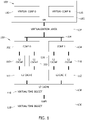
- FIG. 1 is a block diagram of an example memory structure for a host computer having a host central processing unit (CPU) 100, having one or multiple cores.
- host CPU 100 includes at least two cores including a core 0 102 and a core 1 104.
- Host CPU 100 is configured, or programmed, to execute a VM 105 using a virtualization layer 107.
- VM 105 is configured to execute target code, or software, having multiple threads, tasks, and/or processes that may be processed serially or in parallel on a target multicore processor.
- VM 105 includes a virtual multicore processor 103 having N virtual cores 116.
- FIG. 2 is an example timing diagram 200 of serial processing of the multi-threaded target code.
- FIG. 1 is a block diagram of an example memory structure for a host computer having a host central processing unit (CPU) 100, having one or multiple cores.
- host CPU 100 includes at least two cores including a core 0 102 and a core 1 104.
- FIG. 3 is an example timing diagram 300 of parallel processing of the multi-threaded target code.
- FIG. 2 illustrates four threads executing serially on respective virtual cores 202, 204, 206, 208. Sections of code 210, 212, 214, 216 in each thread execute sequentially on virtual cores 202, 204, 206, 208 over virtual time, which is represented on a virtual time axis 218.
- the time required to execute the four threads serially is a factor of four longer than executing the same threads in parallel, as shown in FIG. 3 .
- timekeeping can simply progress serially with the threads in virtual time.
- timing diagram 300 illustrates the same virtual cores 202, 204, 206, 208 processing the same target code 302, 304, 306, 308 in parallel.
- Each target code 302, 304, 306, 308 include a unique set of executable instructions that vary in the time necessary to process by their respective virtual cores 202, 204, 206, 208.
- Virtual cores 202, 204, 206, 208 process in parallel and track virtual time with a virtual time object, and without synchronizing virtual time with wall-clock time. Because each thread of target code 302, 304, 306, 308 is unequal in its time required for execution of instructions, timekeeping is distributed among all virtual cores 202, 204, 206, 208.
- FIG. 3 illustrates four virtual cores
- the disclosed timekeeping method may be embodied in a virtualized multicore processor having any number, N, of virtual cores, i.e., two or more.
- the virtual time object 118 is stored in a section of memory accessible by virtualization layer 107 for use by all virtual cores 116 in VM 105, from virtual core 0 116 to virtual core N 116.
- the memory space may include, for example, an address in random access memory (RAM) 106.
- RAM random access memory
- the target code itself, including its multiple threads, each composed of multiple executable instructions, may also be stored in RAM 106.
- target code may be stored in another memory space, such as a non-volatile RAM (NVRAM) or a mass storage device.
- NVRAM non-volatile RAM
- the memory space storing the virtual time object 118 may include an address in a shared cache, such as a layer 3 (L3) cache 108.
- a shared cache such as a layer 3 (L3) cache 108.
- each host core has one or more dedicated cache memory spaces.
- the dedicated cache may include, for example, one or more layer 1 (L1) cache 110 and one or more layer 2 (L2) cache 112.
- L1 cache 110 is typically the smallest volume of memory, but the fastest.
- L2 cache 112 is typically larger than L1 cache 110, but has slower read and write times.
- L3 cache 108 is even larger, but again has slower read and write times.
- one or more of the dedicated cache memories (L1 110 or L2 112) is incorporated with its corresponding host core, e.g., core 0 102 or core 1 104.
- the virtual time object 118 may be stored in another memory space coupled to the host cores over, for example, a memory bus 114.
- VM 105 tracks virtual time by counting the number of emulated instructions executed and then incrementing the virtual time object 118.
- only one virtual core can increment, or advance, the virtual time object 118 at a given moment in time, because that one core locks the memory space, e.g., L3 cache 108. Consequently, one or more other virtual cores may stop processing its thread to preserve cache coherency, resulting in degraded performance of virtualized multicore processor 103.
- cache coherency issues compound.
- one virtual core increments virtual time, because virtual time advances too quickly (e.g., faster than wall-clock time) when all threads increment virtual time. For example, a virtual processor with N cores advances virtual time N-times faster than with a single core or serially executing cores.
- the VM 105 designates, or assigns a designation to, a first virtual core, e.g., virtual core N 116, to increment the virtual time object 118 by its count of the instructions executed in its thread of target code over a first duration.
- the designation is then moved to another virtual core 116 in response to detecting an event that defines an end of the first duration. That virtual core 116 then increments the virtual time object 118 by its count of instructions executed in its thread of target code over a second duration. All virtual cores otherwise execute their respective threads in parallel and only the designated virtual core increments the virtual time object 118.
- the instructions, i.e., the target code, executed in a given thread by a corresponding virtual core may include, for example, a block of assembly language instructions. Those instructions may also include instructions to read the virtual time object 118 from time to time, e.g., periodically, which functions to synchronize the multiple threads and their corresponding virtual cores. Alternatively, the VM 105 may periodically instruct each virtual core to read the virtual time object 118.
- timekeeper is moved in response to an event, such as an interrupt, the completion of execution of a translation block of instructions, or the halting of the virtual core that holds the designation of timekeeper.
- the moving designation avoids locking the shared memory space, which can cause one or more virtual cores 116 to halt execution.
- processing loads of the virtual cores 116 are often unequal, or unbalanced, at a given moment in time, over a longer duration, as each virtual core 116 contributes to the incrementing, or advancing of virtual time, the unequal processing loads across the virtual cores 116 are smoothed, or tend toward average.
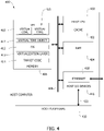
- FIG. 4 is a block diagram of an example host computer 400 for emulating a target multicore processor.
- the target multicore processor is a hardware multi-core processor to be emulated.
- a computing system i.e., the target hardware, may utilize a dual-core or quad-core processor.
- the target multicore processor may include eight or more processing cores.
- the target multicore processor includes two or more processing cores.
- Host computer 400 includes host CPU 402 coupled to a cache memory 403, and further coupled to RAM 404 and host memory 406 via a memory bus 408.
- Cache memory 403 and RAM 404 are configured to operate with host CPU 402 as multicore processor 100 operates with RAM 106 and the corresponding cache memory shown in FIG. 1 .
- Host memory 406 is a computer-readable memory (e.g., volatile or non-volatile) that includes a memory section storing a VM 410, a section storing an OS 412, a section storing a virtualization layer 413, a section storing target code 414, and a section storing a virtual time object 417, such as a variable, a data structure, or a class.
- a virtual time object 417 such as a variable, a data structure, or a class.
- one or more section of host memory 406 may be omitted and the data stored remotely.
- target code 414 may be stored remotely on a server or mass-storage device, and made available over a network to host CPU 402 and VM 410.
- VM 410 includes virtualized multicore processor 415.
- Host computer 400 also includes host I/O devices 416, which may include, for example, a communication interface such as an Ethernet controller 418, or a peripheral interface for communicating with a host peripheral device 420 over a peripheral link 422.
- host I/O devices 416 may include, for example, a GPU for operating a display peripheral over a display link.
- FIG. 5 is a flow diagram of an example method 500 of tracking virtual time in a VM having a virtual multicore processor, such as VM 410 and virtualized multicore processor 100 shown in FIGS. 4 and 1 , respectively.
- a first virtual core e.g., virtual core 0 116
- a second core e.g., virtual core N 116
- a virtual time object 417 is stored 506 in a section of host memory shared between at least the first and second virtual cores.
- the virtual time object 417 may be stored in L3 cache 108, which is shared by virtual core 0 116 and virtual core N 116.
- the VM assigns 508 a designation to the first virtual core to increment the virtual time object 417 by a first count of the first plurality of instructions executed in the first thread over a first duration.
- the designation is then moved 510 to the second virtual core in response to detecting an event that defines an end of the first duration.
- the event may include an interrupt, the completion of execution of a section of code, e.g., a translation block, or the halting of the first virtual core.
- the second virtual core increments 512 the virtual time object 417 by a second count of the second plurality of instructions executed in the second thread over a second duration.
- Virtual cores execute in parallel and only one virtual core updates virtual time.
- method 500 includes mapping the shared cache, e.g., L3 cache 108, to a shared cache for a host multicore processor.
- method 500 includes reading, by the second virtual core, the virtual time object 417 during the first duration. The reading may be by an instruction in the second thread or, alternatively, by instruction from the VM.
- An example technical effect of the methods, systems, and apparatus described herein includes at least one of: (a) tracking virtual time in a virtualized multicore processor executing multiple target code threads in parallel; (b) eliminating wall-clock synchronization of virtual time; (c) storing a virtual time object in a shared memory space without disrupting cache coherency; and (d) distributing timekeeping among the multiple virtual cores by moving the timekeeping designation on an event-driven basis.
- processors and “computer” and related terms, e.g., "processing device,” “computing device,” and “controller” are not limited to just those integrated circuits referred to in the art as a computer, but broadly refers to a processor, a processing device, a controller, a general purpose central processing unit (CPU), a graphics processing unit (GPU), a microcontroller, a microcomputer, a programmable logic controller (PLC), a reduced instruction set computer (RISC) processor, a field programmable gate array (FPGA), a digital signal processing (DSP) device, an application specific integrated circuit (ASIC), and other programmable circuits or processing devices capable of executing the functions described herein, and these terms are used interchangeably herein.
- PLC programmable logic controller
- RISC reduced instruction set computer
- FPGA field programmable gate array
- DSP digital signal processing
- ASIC application specific integrated circuit
- memory may include, but is not limited to, a non-transitory computer-readable medium, such as flash memory, a random access memory (RAM), read-only memory (ROM), erasable programmable read-only memory (EPROM), electrically erasable programmable read-only memory (EEPROM), and non-volatile RAM (NVRAM).
- a non-transitory computer-readable medium such as flash memory, a random access memory (RAM), read-only memory (ROM), erasable programmable read-only memory (EPROM), electrically erasable programmable read-only memory (EEPROM), and non-volatile RAM (NVRAM).
- RAM random access memory
- ROM read-only memory
- EPROM erasable programmable read-only memory
- EEPROM electrically erasable programmable read-only memory
- NVRAM non-volatile RAM
- non-transitory computer-readable media is intended to be representative of any tangible, computer-readable media, including, without limitation, non-transitory computer storage devices, including, without limitation, volatile and non-volatile media, and removable and non-removable media such as a firmware, physical and virtual storage, CD-ROMs, DVDs, and any other digital source such as a network or the Internet, as well as yet to be developed digital means, with the sole exception being a transitory, propagating signal.
- a floppy disk a compact disc - read only memory (CD-ROM), a magneto-optical disk (MOD), a digital versatile disc (DVD), or any other computer-based device implemented in any method or technology for short-term and long-term storage of information, such as, computer-readable instructions, data structures, program modules and sub-modules, or other data
- the methods described herein may be encoded as executable instructions, e.g., "software” and "firmware,” embodied in a non-transitory computer-readable medium.
- the terms "software” and “firmware” are interchangeable, and include any computer program stored in memory for execution by personal computers, workstations, clients and servers. Such instructions, when executed by a processor, cause the processor to perform at least a portion of the methods described herein.
- additional input channels may be, but are not limited to, computer peripherals associated with an operator interface such as a mouse and a keyboard.
- other computer peripherals may also be used that may include, for example, but not be limited to, a scanner.
- additional output channels may include, but not be limited to, an operator interface monitor.
Landscapes
- Engineering & Computer Science (AREA)
- Software Systems (AREA)
- Theoretical Computer Science (AREA)
- Physics & Mathematics (AREA)
- General Engineering & Computer Science (AREA)
- General Physics & Mathematics (AREA)
- Memory System Of A Hierarchy Structure (AREA)
Abstract
Description
- The field of the disclosure relates generally to virtualization of multicore processors and, more specifically, to tracking virtual time in a virtual machine having multiple virtual cores processing in parallel.
- Computing systems are often virtualized, or emulated, to enable simulation, testing, and development of that computing environment on a host computer, such as a desktop personal computer. Virtualization refers to the imitation of a given unit of hardware by a software program, such as a virtual machine (VM), executing on a local, or host, computer via a hypervisor. In some instances, VMs execute without a hypervisor. Virtualization enables development, testing, and execution of target software without the need for a complete target computing system, which may have limited availability.
- At least some of those computing systems utilize a multicore processor and multi-thread, or parallel, processing of target software. In some instances, multiprocessing hardware is used instead of, or in combination with, multicore processors to provide multiple processor cores for parallel execution. When that target software includes multiple threads, tasks, and/or processes intended to execute in parallel on a multicore processor or on multiple processors, execution of that target software and, more specifically, the multiple threads on multiple virtual cores demands that the threads be synchronized or coordinated in some manner. One solution is to execute the threads serially in an incremental manner, e.g., from interrupt to interrupt. However, this results in degradation of the VM's performance, particularly as the number of threads and target processing cores increases. Another solution is to synchronize virtual time, i.e., the timing within the VM, with "wall clock" time, i.e., actual time in the physical world, however, if the virtualized system cannot execute software fast enough to match wall clock time, then it is often not possible to achieve synchronization, which can be the case when processor emulation is used in the virtual machine. In other scenarios, it is desirable to run faster than wall clock time, and in this scenario wall clock time cannot easily be used as a time source and a synchronized virtual time source is required. Moreover, these conventional solutions result in an inability to produce VMs that match the desired performance characteristics for multicore applications using VMs such as test environments and trainers. Accordingly, improved timekeeping for VMs having multiple virtual processing cores is desired.
- For the purpose of this disclosure, the terms "virtualization" and "emulation" are used interchangeably to refer to a VM where any aspect of target hardware is being emulated, although the host computer may incorporate one or more other aspect of target hardware.
- This section is intended to introduce the reader to various aspects of art that may be related to various aspects of the present disclosure, which are described and/or claimed below. This discussion is believed to be helpful in providing the reader with background information to facilitate a better understanding of the various aspects of the present disclosure. Accordingly, it should be understood that these statements are to be read in this light, and not as admissions of prior art.
- One aspect is directed to a host computer for virtualizing a target multicore processor. The host computer includes a host memory and a host CPU. The host memory includes a first section of memory storing a virtual time object, and a second section storing a VM. The VM includes target code having a plurality of threads, wherein each thread includes a plurality of instructions configured to execute on the target multicore processor. The host CPU is configured to execute the VM to virtualize the target multicore processor. The VM is configured to execute the plurality of threads in parallel on corresponding virtual cores, including a first thread having a first plurality of instructions executing on a first virtual core and a second thread having a second plurality of instructions executing on a second virtual core. The VM is further configured to assign a designation to the first virtual core to increment the virtual time object by a first count of the first plurality of instructions executed in the first thread over a first duration. The VM is further configured to move the designation to the second virtual core in response to detecting an event that defines an end of the first duration. The VM is further configured to increment, by the second virtual core, the virtual time object by a second count of the second plurality of instructions executed in the second thread over a second duration.
- Another aspect is directed to a method of tracking virtual time in a VM having a virtual multicore processor. The method includes executing a first thread on a first virtual core, wherein the first thread includes a first plurality of instructions. The method includes executing a second thread on a second virtual core in parallel with the first thread, wherein the second thread includes a second plurality of instructions. The method includes storing a virtual time object in a section of host memory. The method includes assigning a designation to the first virtual core to increment the virtual time object by a first count of the first plurality of instructions executed in the first thread over a first duration. The method includes moving the designation to the second virtual core in response to detecting an event that defines an end of the first duration. The method includes incrementing, by the second virtual core, the virtual time object by a second count of the second plurality of instructions executed in the second thread over a second duration.
- Yet another aspect is directed to a computer-readable memory storing a VM having a plurality of virtual cores. The VM, upon execution by a host CPU, is configured to execute a first thread on a first virtual core of the plurality of virtual cores, wherein the first thread includes a first plurality of instructions, and execute a second thread on a second virtual core, of the plurality of virtual cores, in parallel with the first thread, wherein the second thread includes a second plurality of instructions. The VM stores a virtual time object in a section of host memory, and assigns a designation to the first virtual core to increment the virtual time object by a first count of the first plurality of instructions executed in the first thread over a first duration. The VM moves the designation to the second virtual core in response to detecting an event that defines an end of the first duration. The second virtual core increments the virtual time object by a second count of the second plurality of instructions executed in the second thread over a second duration.
- Various refinements exist of the features noted in relation to the above-mentioned aspects. Further features may also be incorporated in the above-mentioned aspects as well. These refinements and additional features may exist individually or in any combination. For instance, various features discussed below in relation to any of the illustrated examples may be incorporated into any of the above-described aspects, alone or in any combination.
-
-
FIG. 1 is a block diagram of an example memory structure for a host computer executing a VM; -
FIG. 2 is an example timing diagram of serial processing of multi-threaded target code; -
FIG. 3 is an example timing diagram of parallel processing of multi-threaded target code; -
FIG. 4 is a block diagram of an example host computer; and -
FIG. 5 is a flow diagram of an example method of tracking virtual time in a VM having a virtual multicore processor. - Corresponding reference characters indicate corresponding parts throughout the several views of the drawings. Although specific features of various examples may be shown in some drawings and not in others, this is for convenience only. Any feature of any drawing may be referenced and/or claimed in combination with any feature of any other drawing.
- The host computer disclosed provides a virtual time object stored in a memory section such that it can be used in the virtualization layer by multiple virtualized cores of the VM. The virtual time object may include, for example, a variable, data structure, or class in which virtual time can be stored. When executing target code having multiple threads executed in parallel, the VM designates one virtual core as the timekeeper to increment the virtual time object by a count of its instructions executed, and then the VM moves the designation to another virtual core that, likewise, increments the virtual time object by its count of its instructions executed. The designation may include a variable, data structure, class, Boolean, flag or other read/write software structure that can identify a given virtual core as the timekeeper. The designation of timekeeper may be moved, for example, in response to detecting an event, such as an interrupt or completion of execution of a translation block of code.
- A translation block is created when processor emulation is used within a VM. Translation blocks improve performance of processor emulation. In direct processor emulation (i.e., without translation blocks), every instruction in the target software is encountered logic in the processor emulation, and the VM translates that target software (e.g., assembly or machine code) to host code (e.g., host assembly or machine code). Translation blocks enable blocks of target software to be translated and cached for future use during execution. This caching is possible because the target software binary does not change and most software is cyclic in nature and only executes a small percentage of all overall code in the binary. Translation blocks are variable in length and are designed to end at some transition in the code, such as, for example, a branch statement or a context switch. These transitions in the code cause the translation block being worked on in the processor emulator to be moved out and a new translation block loaded into the processor emulator. The transition of translation blocks is conceptually similar to context switches.
-
FIG. 1 is a block diagram of an example memory structure for a host computer having a host central processing unit (CPU) 100, having one or multiple cores. Referring to the example shown inFIG. 1 ,host CPU 100 includes at least two cores including acore 0 102 and acore 1 104.Host CPU 100 is configured, or programmed, to execute aVM 105 using avirtualization layer 107.VM 105 is configured to execute target code, or software, having multiple threads, tasks, and/or processes that may be processed serially or in parallel on a target multicore processor.VM 105 includes a virtualmulticore processor 103 having Nvirtual cores 116.FIG. 2 is an example timing diagram 200 of serial processing of the multi-threaded target code.FIG. 3 is an example timing diagram 300 of parallel processing of the multi-threaded target code.FIG. 2 illustrates four threads executing serially on respectivevirtual cores code virtual cores virtual time axis 218. Notably, the time required to execute the four threads serially is a factor of four longer than executing the same threads in parallel, as shown inFIG. 3 . However, timekeeping can simply progress serially with the threads in virtual time. - In
FIG. 3 , timing diagram 300 illustrates the samevirtual cores same target code target code virtual cores Virtual cores target code virtual cores FIG. 3 illustrates four virtual cores, the disclosed timekeeping method may be embodied in a virtualized multicore processor having any number, N, of virtual cores, i.e., two or more. - Referring to
host CPU 100 shown inFIG. 1 , thevirtual time object 118 is stored in a section of memory accessible byvirtualization layer 107 for use by allvirtual cores 116 inVM 105, fromvirtual core 0 116 tovirtual core N 116. The memory space may include, for example, an address in random access memory (RAM) 106. The target code itself, including its multiple threads, each composed of multiple executable instructions, may also be stored inRAM 106. Alternatively, target code may be stored in another memory space, such as a non-volatile RAM (NVRAM) or a mass storage device. - Alternatively, the memory space storing the
virtual time object 118 may include an address in a shared cache, such as a layer 3 (L3)cache 108. Generally, each host core has one or more dedicated cache memory spaces. The dedicated cache may include, for example, one or more layer 1 (L1)cache 110 and one or more layer 2 (L2)cache 112. Each additional layer of cache memory is generally larger and slower than the next lower level. For example,L1 cache 110 is typically the smallest volume of memory, but the fastest.L2 cache 112 is typically larger thanL1 cache 110, but has slower read and write times. Likewise,L3 cache 108 is even larger, but again has slower read and write times. In certain embodiments, one or more of the dedicated cache memories (L1 110 or L2 112) is incorporated with its corresponding host core, e.g.,core 0 102 orcore 1 104. In alternative embodiments, thevirtual time object 118 may be stored in another memory space coupled to the host cores over, for example, amemory bus 114. - For each
virtual core 116, for example,virtual core 0 116 andvirtual core N 116,VM 105 tracks virtual time by counting the number of emulated instructions executed and then incrementing thevirtual time object 118. However, only one virtual core can increment, or advance, thevirtual time object 118 at a given moment in time, because that one core locks the memory space, e.g.,L3 cache 108. Consequently, one or more other virtual cores may stop processing its thread to preserve cache coherency, resulting in degraded performance of virtualizedmulticore processor 103. As the number of virtual cores increases, cache coherency issues compound. Moreover, one virtual core increments virtual time, because virtual time advances too quickly (e.g., faster than wall-clock time) when all threads increment virtual time. For example, a virtual processor with N cores advances virtual time N-times faster than with a single core or serially executing cores. - The
VM 105 designates, or assigns a designation to, a first virtual core, e.g.,virtual core N 116, to increment thevirtual time object 118 by its count of the instructions executed in its thread of target code over a first duration. The designation is then moved to anothervirtual core 116 in response to detecting an event that defines an end of the first duration. Thatvirtual core 116 then increments thevirtual time object 118 by its count of instructions executed in its thread of target code over a second duration. All virtual cores otherwise execute their respective threads in parallel and only the designated virtual core increments thevirtual time object 118. - The instructions, i.e., the target code, executed in a given thread by a corresponding virtual core may include, for example, a block of assembly language instructions. Those instructions may also include instructions to read the
virtual time object 118 from time to time, e.g., periodically, which functions to synchronize the multiple threads and their corresponding virtual cores. Alternatively, theVM 105 may periodically instruct each virtual core to read thevirtual time object 118. - The designation of timekeeper is moved in response to an event, such as an interrupt, the completion of execution of a translation block of instructions, or the halting of the virtual core that holds the designation of timekeeper. The moving designation avoids locking the shared memory space, which can cause one or more
virtual cores 116 to halt execution. Although processing loads of thevirtual cores 116 are often unequal, or unbalanced, at a given moment in time, over a longer duration, as eachvirtual core 116 contributes to the incrementing, or advancing of virtual time, the unequal processing loads across thevirtual cores 116 are smoothed, or tend toward average. -
FIG. 4 is a block diagram of anexample host computer 400 for emulating a target multicore processor. The target multicore processor is a hardware multi-core processor to be emulated. For example, a computing system, i.e., the target hardware, may utilize a dual-core or quad-core processor. Alternatively, the target multicore processor may include eight or more processing cores. Generally, the target multicore processor includes two or more processing cores.Host computer 400 includeshost CPU 402 coupled to acache memory 403, and further coupled toRAM 404 andhost memory 406 via amemory bus 408.Cache memory 403 andRAM 404 are configured to operate withhost CPU 402 asmulticore processor 100 operates withRAM 106 and the corresponding cache memory shown inFIG. 1 . More specifically, the virtual time variable is stored in a memory space allocated inRAM 404 or incache memory 403.Host memory 406 is a computer-readable memory (e.g., volatile or non-volatile) that includes a memory section storing aVM 410, a section storing anOS 412, a section storing avirtualization layer 413, a section storingtarget code 414, and a section storing avirtual time object 417, such as a variable, a data structure, or a class. In alternative embodiments, one or more section ofhost memory 406 may be omitted and the data stored remotely. For example, in certain embodiments,target code 414 may be stored remotely on a server or mass-storage device, and made available over a network to hostCPU 402 andVM 410.VM 410 includes virtualizedmulticore processor 415. -
Host computer 400 also includes host I/O devices 416, which may include, for example, a communication interface such as anEthernet controller 418, or a peripheral interface for communicating with a hostperipheral device 420 over aperipheral link 422. Host I/O devices 416 may include, for example, a GPU for operating a display peripheral over a display link. -
FIG. 5 is a flow diagram of anexample method 500 of tracking virtual time in a VM having a virtual multicore processor, such asVM 410 and virtualizedmulticore processor 100 shown inFIGS. 4 and1 , respectively. A first virtual core, e.g.,virtual core 0 116, executes 502 a first thread that includes a first plurality of instructions. A second core, e.g.,virtual core N 116, executes 504 a second thread that includes a second plurality of instructions. Avirtual time object 417 is stored 506 in a section of host memory shared between at least the first and second virtual cores. For example, as shown inFIG. 1 , thevirtual time object 417 may be stored inL3 cache 108, which is shared byvirtual core 0 116 andvirtual core N 116. - The VM assigns 508 a designation to the first virtual core to increment the
virtual time object 417 by a first count of the first plurality of instructions executed in the first thread over a first duration. The designation is then moved 510 to the second virtual core in response to detecting an event that defines an end of the first duration. For example, the event may include an interrupt, the completion of execution of a section of code, e.g., a translation block, or the halting of the first virtual core. The second virtual core thenincrements 512 thevirtual time object 417 by a second count of the second plurality of instructions executed in the second thread over a second duration. Virtual cores execute in parallel and only one virtual core updates virtual time. - In certain embodiments,
method 500 includes mapping the shared cache, e.g.,L3 cache 108, to a shared cache for a host multicore processor. In certain embodiments,method 500 includes reading, by the second virtual core, thevirtual time object 417 during the first duration. The reading may be by an instruction in the second thread or, alternatively, by instruction from the VM. - An example technical effect of the methods, systems, and apparatus described herein includes at least one of: (a) tracking virtual time in a virtualized multicore processor executing multiple target code threads in parallel; (b) eliminating wall-clock synchronization of virtual time; (c) storing a virtual time object in a shared memory space without disrupting cache coherency; and (d) distributing timekeeping among the multiple virtual cores by moving the timekeeping designation on an event-driven basis.
- Some embodiments involve the use of one or more electronic processing or computing devices. As used herein, the terms "processor" and "computer" and related terms, e.g., "processing device," "computing device," and "controller" are not limited to just those integrated circuits referred to in the art as a computer, but broadly refers to a processor, a processing device, a controller, a general purpose central processing unit (CPU), a graphics processing unit (GPU), a microcontroller, a microcomputer, a programmable logic controller (PLC), a reduced instruction set computer (RISC) processor, a field programmable gate array (FPGA), a digital signal processing (DSP) device, an application specific integrated circuit (ASIC), and other programmable circuits or processing devices capable of executing the functions described herein, and these terms are used interchangeably herein. These processing devices are generally "configured" to execute functions by programming or being programmed, or by the provisioning of instructions for execution. The above examples are not intended to limit in any way the definition or meaning of the terms processor, processing device, and related terms.
- In the embodiments described herein, memory may include, but is not limited to, a non-transitory computer-readable medium, such as flash memory, a random access memory (RAM), read-only memory (ROM), erasable programmable read-only memory (EPROM), electrically erasable programmable read-only memory (EEPROM), and non-volatile RAM (NVRAM). As used herein, the term "non-transitory computer-readable media" is intended to be representative of any tangible, computer-readable media, including, without limitation, non-transitory computer storage devices, including, without limitation, volatile and non-volatile media, and removable and non-removable media such as a firmware, physical and virtual storage, CD-ROMs, DVDs, and any other digital source such as a network or the Internet, as well as yet to be developed digital means, with the sole exception being a transitory, propagating signal. Alternatively, a floppy disk, a compact disc - read only memory (CD-ROM), a magneto-optical disk (MOD), a digital versatile disc (DVD), or any other computer-based device implemented in any method or technology for short-term and long-term storage of information, such as, computer-readable instructions, data structures, program modules and sub-modules, or other data may also be used. Therefore, the methods described herein may be encoded as executable instructions, e.g., "software" and "firmware," embodied in a non-transitory computer-readable medium. Further, as used herein, the terms "software" and "firmware" are interchangeable, and include any computer program stored in memory for execution by personal computers, workstations, clients and servers. Such instructions, when executed by a processor, cause the processor to perform at least a portion of the methods described herein.
- Also, in the embodiments described herein, additional input channels may be, but are not limited to, computer peripherals associated with an operator interface such as a mouse and a keyboard. Alternatively, other computer peripherals may also be used that may include, for example, but not be limited to, a scanner. Furthermore, in some embodiments, additional output channels may include, but not be limited to, an operator interface monitor.
- The systems and methods described herein are not limited to the specific embodiments described herein, but rather, components of the systems and/or steps of the methods may be utilized independently and separately from other components and/or steps described herein.
- Although specific features of various embodiments of the disclosure may be shown in some drawings and not in others, this is for convenience only. In accordance with the principles of the disclosure, any feature of a drawing may be referenced and/or claimed in combination with any feature of any other drawing.
- As used herein, an element or step recited in the singular and proceeded with the word "a" or "an" should be understood as not excluding plural elements or steps unless such exclusion is explicitly recited. Furthermore, references to "one embodiment" of the present invention or the "exemplary embodiment" are not intended to be interpreted as excluding the existence of additional embodiments that also incorporate the recited features.
- Further, the disclosure comprises embodiments according to the following clauses:
-
Clause 1. A host computer (400) for virtualizing a target multicore processor, the host computer comprising:- a host memory (406) including a first section of memory storing a virtual time object (118, 417), and a second section storing a virtual machine (VM) (105, 410), wherein the VM includes target code (414) comprises a plurality of threads, wherein each thread includes a plurality of instructions configured to execute on the target multicore processor; and
- a host central processing unit (CPU) (100, 402) configured to execute the VM to virtualize the target multicore processor, the VM configured to:
- execute the plurality of threads in parallel on corresponding virtual cores (116, 415), including a first thread having a first plurality of instructions executing on a first virtual core and a second thread having a second plurality of instructions executing on a second virtual core;
- assign a designation to the first virtual core to increment the virtual time object by a first count of the first plurality of instructions executed in the first thread over a first duration;
- move the designation to the second virtual core in response to detecting an event that defines an end of the first duration; and
- increment, by the second virtual core, the virtual time object by a second count of the second plurality of instructions executed in the second thread over a second duration.
- Clause 2. The host computer (400) of
clause 1, wherein the event is an interrupt. - Clause 3. The host computer (400) of
clause 1, wherein the event is completion of execution of a translation block in the first plurality of instructions. - Clause 4. The host computer (400) of any one of clauses 1-3, wherein the second plurality of instructions executing on the second virtual core (116, 415) includes a read of the virtual time object (118, 417) during the first duration.
- Clause 5. The host computer (400) of any one of clauses 1-4, wherein the VM (105, 410) is further configured to periodically read the virtual time object (118, 417) to update at least one of an emulated counter or an emulated hardware timer in the VM
- Clause 6. The host computer (400) of any one of clauses 1-5, wherein the plurality of instructions for each thread includes assembly instructions.
- Clause 7. The host computer (400) of
clause 1, wherein the event is a halting of the first virtual core (116, 415). - Clause 8. The host computer (400) of any one of clauses 1-7, wherein the first section of the host memory is mapped to a shared cache level (108) for storing the virtual time object (118, 417).
- Clause 9. A method (500) of tracking virtual time in a virtual machine (VM) (105, 410) having a virtual multicore processor (103), the method comprising:
- executing (502) a first thread on a first virtual core (116, 415), wherein the first thread includes a first plurality of instructions;
- executing (504) a second thread on a second virtual core (116, 415) in parallel with the first thread, wherein the second thread includes a second plurality of instructions;
- storing (506) a virtual time object (118, 417) in a section of host memory (406);
- assigning (508) a designation to the first virtual core to increment the virtual time object by a first count of the first plurality of instructions executed in the first thread over a first duration;
- moving (510) the designation to the second virtual core in response to detecting an event that defines an end of the first duration; and
- incrementing (512), by the second virtual core, the virtual time object by a second count of the second plurality of instructions executed in the second thread over a second duration.
- Clause 10. The method (500) of clause 9, further comprising detecting the event, wherein the event includes a halting of execution by the first virtual core.
- Clause 11. The method (500) of clause 9 or 10, wherein storing (506) the virtual time object (118, 417) comprises storing the virtual time object in a section of random access memory (RAM) (404).
- Clause 12. The method (500) of any one of clauses 9-11, further comprising reading, by the second virtual core (116, 415), the virtual time object (118, 417) during the first duration.
- Clause 13. The method (500) of any one of clauses 9-12, further comprising reading, by the VM (105, 410), the virtual time object (118, 417) to update at least one of an emulated counter or an emulated hardware timer in the VM.
- Clause 14. The method (500) of clause 9, further comprising detecting the event, wherein the event includes an interrupt.
- Clause 15. The method (500) of any one of clauses 9-13, further comprising detecting the event, wherein the event includes completing execution of a translation block of instructions of the first plurality of instructions.
- Clause 16. A computer-readable memory (406) storing a virtual machine (VM) (105, 410) having a plurality of virtual cores (116, 415), the VM, upon execution by a host central processing unit (CPU) (100, 402), configured to:
- execute a first thread on a first virtual core of the plurality of virtual cores (116, 415), wherein the first thread includes a first plurality of instructions;
- execute a second thread on a second virtual core, of the plurality of virtual cores, in parallel with the first thread, wherein the second thread includes a second plurality of instructions;
- store a virtual time object (118, 417) in a section of host memory (403, 404, 406);
- assign a designation to the first virtual core to increment the virtual time object by a first count of the first plurality of instructions executed in the first thread over a first duration;
- move the designation to the second virtual core in response to detecting an event that defines an end of the first duration; and
- increment, by the second virtual core, the virtual time object by a second count of the second plurality of instructions executed in the second thread over a second duration.
- Clause 17. The computer-readable memory (406) of clause 16, wherein the VM (105, 410) is further configured, upon execution by the host CPU (100, 402), to detect the event, wherein the event includes an interrupt.
- Clause 18. The computer-readable memory (406) of clause 17, wherein the VM (105, 410) is further configured, upon execution by the host CPU (100, 402), to detect the event, wherein the event includes completion of execution of a translation block of target code.
- Clause 19. The computer-readable memory (406) of any one of clauses 16-18, wherein the VM (105, 410) is further configured, upon execution by the host CPU (100402), to read, by the second virtual core (116, 415), the virtual time object (118, 417) during the first duration.
- Clause 20. The computer-readable memory (406) of any one of clauses 16-19, wherein the VM (105, 410) is further configured, upon execution by the host CPU (100, 402), to detect the event, wherein the event includes a halting of execution by the first virtual core (116, 415).
- This written description uses examples to disclose various embodiments, which include the best mode, to enable any person skilled in the art to practice those embodiments, including making and using any devices or systems and performing any incorporated methods. The patentable scope is defined by the claims, and may include other examples that occur to those skilled in the art. Such other examples are intended to be within the scope of the claims if they have structural elements that do not differ from the literal language of the claims, or if they include equivalent structural elements with insubstantial differences from the literal languages of the claims.
Claims (15)
- A host computer (400) for virtualizing a target multicore processor, the host computer (400) comprising:a host memory (406) including a first section of memory storing a virtual time object (118, 417), and a second section storing a virtual machine, VM, (105, 410), wherein the VM (105, 410) includes target code (414) comprising a plurality of threads, wherein each thread includes a plurality of instructions configured to execute on the target multicore processor; anda host central processing unit, CPU, (100, 402) configured to execute the VM (105, 410) to virtualize the target multicore processor, the VM (105, 410) being configured to:execute the plurality of threads in parallel on corresponding virtual cores (116, 415), including a first thread having a first plurality of instructions executing on a first virtual core and a second thread having a second plurality of instructions executing on a second virtual core;assign a designation to the first virtual core to increment the virtual time object (118, 417) by a first count of the first plurality of instructions executed in the first thread over a first duration;move the designation to the second virtual core in response to detecting an event that defines an end of the first duration; andincrement, by the second virtual core, the virtual time object (118, 417) by a second count of the second plurality of instructions executed in the second thread over a second duration.
- The host computer (400) of claim 1, wherein the event is an interrupt.
- The host computer (400) of claim 1, wherein the event is completion of execution of a translation block in the first plurality of instructions.
- The host computer (400) of any one of claims 1-3, wherein the second plurality of instructions executing on the second virtual core (116, 415) includes a read of the virtual time object (118,417) during the first duration.
- The host computer (400) of any one of claims 1-4, wherein the VM (105, 410) is further configured to periodically read the virtual time object (118, 417) to update at least one of an emulated counter or an emulated hardware timer in the VM (105, 410).
- The host computer (400) of any one of claims 1-5, wherein the first section of the host memory (406) is mapped to a shared cache level (108) for storing the virtual time object (118, 417).
- A method (500) of tracking virtual time in a virtual machine, VM, (105, 410) having a virtual multicore processor (103), the method (500) comprising:executing (502) a first thread on a first virtual core (116, 415), wherein the first thread includes a first plurality of instructions;executing (504) a second thread on a second virtual core (116, 415) in parallel with the first thread, wherein the second thread includes a second plurality of instructions;storing (506) a virtual time object (118, 417) in a section of a host memory (406);assigning (508) a designation to the first virtual core to increment the virtual time object (118, 417) by a first count of the first plurality of instructions executed in the first thread over a first duration;moving (510) the designation to the second virtual core in response to detecting an event that defines an end of the first duration; andincrementing (512), by the second virtual core, the virtual time object (118, 417) by a second count of the second plurality of instructions executed in the second thread over a second duration.
- The method (500) of claim 7, further comprising detecting the event, wherein the event includes a halting of execution by the first virtual core.
- The method (500) of claim 7 or 8, further comprising reading, by the second virtual core (116, 415), the virtual time object (118, 417) during the first duration.
- The method (500) of any one of claims 7-9, further comprising reading, by the VM (105, 410), the virtual time object (118, 417) to update at least one of an emulated counter or an emulated hardware timer in the VM (105, 410).
- A computer-readable host memory (406) storing a virtual machine, VM, (105, 410) having a plurality of virtual cores (116, 415), the VM (150, 410), upon execution by a host central processing unit, CPU, (100, 402), being configured to:execute a first thread on a first virtual core of the plurality of virtual cores (116, 415), wherein the first thread includes a first plurality of instructions;execute a second thread on a second virtual core, of the plurality of virtual cores (116, 415), in parallel with the first thread, wherein the second thread includes a second plurality of instructions;store a virtual time object (118, 417) in a section of the host memory (403, 404, 406);assign a designation to the first virtual core to increment the virtual time object (118, 417) by a first count of the first plurality of instructions executed in the first thread over a first duration;move the designation to the second virtual core in response to detecting an event that defines an end of the first duration; andincrement, by the second virtual core, the virtual time object (118, 417) by a second count of the second plurality of instructions executed in the second thread over a second duration.
- The computer-readable host memory (406) of claim 11, wherein the VM (105, 410) is further configured, upon execution by the host CPU (100, 402), to detect the event, wherein the event includes an interrupt.
- The computer-readable host memory (406) of claim 11 or 12, wherein the VM (105, 410) is further configured, upon execution by the host CPU (100, 402), to detect the event, wherein the event includes completion of execution of a translation block of target code.
- The computer-readable host memory (406) of any one of claims 11-13, wherein the VM (105, 410) is further configured, upon execution by the host CPU (100, 402), to read, by the second virtual core (116, 415), the virtual time object (118, 417) during the first duration.
- The computer-readable host memory (406) of any one of claims 11-14, wherein the VM (105, 410) is further configured, upon execution by the host CPU (100, 402), to detect the event, wherein the event includes a halting of execution by the first virtual core (116, 415).
Applications Claiming Priority (1)
| Application Number | Priority Date | Filing Date | Title |
|---|---|---|---|
| US202163144725P | 2021-02-02 | 2021-02-02 |
Publications (2)
| Publication Number | Publication Date |
|---|---|
| EP4036722A1 true EP4036722A1 (en) | 2022-08-03 |
| EP4036722B1 EP4036722B1 (en) | 2024-12-11 |
Family
ID=80034866
Family Applications (1)
| Application Number | Title | Priority Date | Filing Date |
|---|---|---|---|
| EP22153443.1A Active EP4036722B1 (en) | 2021-02-02 | 2022-01-26 | System and method of timekeeping for a virtual machine having multiple virtual processing cores |
Country Status (6)
| Country | Link |
|---|---|
| US (1) | US12242876B2 (en) |
| EP (1) | EP4036722B1 (en) |
| JP (1) | JP7785555B2 (en) |
| KR (1) | KR20220111664A (en) |
| CN (1) | CN114840301A (en) |
| CA (1) | CA3146521C (en) |
Families Citing this family (4)
| Publication number | Priority date | Publication date | Assignee | Title |
|---|---|---|---|---|
| CA3146521C (en) * | 2021-02-02 | 2026-01-20 | The Boeing Company | System and method of timekeeping for a virtual machine having multiple virtual processing cores |
| CN113467884B (en) * | 2021-05-25 | 2024-08-02 | 阿里巴巴创新公司 | Resource allocation method and device, electronic equipment and computer readable storage medium |
| EP4357964A1 (en) * | 2022-10-20 | 2024-04-24 | Minres Technologies GmbH | Apparatus and method for synchronizing participants of a simulation |
| CN116070565B (en) * | 2023-03-01 | 2023-06-13 | 摩尔线程智能科技(北京)有限责任公司 | Method and device for simulating multi-core processor, electronic equipment and storage medium |
Citations (2)
| Publication number | Priority date | Publication date | Assignee | Title |
|---|---|---|---|---|
| US20130160012A1 (en) * | 2009-03-30 | 2013-06-20 | Microsoft | Timer access from user mode through a shared memory page |
| US20160085572A1 (en) * | 2014-09-22 | 2016-03-24 | The Boeing Company | Parallelization in virtual machine operation |
Family Cites Families (34)
| Publication number | Priority date | Publication date | Assignee | Title |
|---|---|---|---|---|
| JP3938387B2 (en) * | 2005-08-10 | 2007-06-27 | インターナショナル・ビジネス・マシーンズ・コーポレーション | Compiler, control method, and compiler program |
| US7802073B1 (en) * | 2006-03-29 | 2010-09-21 | Oracle America, Inc. | Virtual core management |
| JP5010164B2 (en) | 2006-03-31 | 2012-08-29 | 株式会社日立製作所 | Server apparatus and virtual machine control program |
| US8082431B2 (en) * | 2006-09-29 | 2011-12-20 | Intel Corporation | System and method for increasing platform boot efficiency |
| US20080244538A1 (en) * | 2007-03-26 | 2008-10-02 | Nair Sreekumar R | Multi-core processor virtualization based on dynamic binary translation |
| JP4864817B2 (en) * | 2007-06-22 | 2012-02-01 | 株式会社日立製作所 | Virtualization program and virtual computer system |
| US7797512B1 (en) * | 2007-07-23 | 2010-09-14 | Oracle America, Inc. | Virtual core management |
| JP5049763B2 (en) * | 2007-12-19 | 2012-10-17 | キヤノン株式会社 | Network timer management method and apparatus |
| US8650570B2 (en) * | 2008-06-02 | 2014-02-11 | Microsoft Corporation | Method of assigning instructions in a process to a plurality of scheduler instances based on the instruction, in which each scheduler instance is allocated a set of negoitaited processor resources |
| US10521265B2 (en) * | 2008-09-19 | 2019-12-31 | Microsoft Technology Licensing, Llc | Coalescing periodic timer expiration in guest operating systems in a virtualized environment |
| US8429665B2 (en) | 2010-03-19 | 2013-04-23 | Vmware, Inc. | Cache performance prediction, partitioning and scheduling based on cache pressure of threads |
| US8239632B2 (en) * | 2009-03-12 | 2012-08-07 | At&T Mobility Ii Llc | Data caching in consolidated network repository |
| US8544010B2 (en) * | 2009-09-18 | 2013-09-24 | Vmware, Inc. | Providing notification to speculatively waking up target virtual machine for an I/O event using multiple virtual machines and processors |
| US9183030B2 (en) * | 2011-04-27 | 2015-11-10 | Microsoft Technology Licensing, Llc | Virtual processor allocation techniques |
| US9003405B1 (en) * | 2012-05-22 | 2015-04-07 | The Boeing Company | Synchronization of virtual machine-based desktop environments |
| JP6000685B2 (en) * | 2012-06-25 | 2016-10-05 | 京セラ株式会社 | Communication terminal, communication control program, and communication control method |
| US8806104B2 (en) * | 2012-09-25 | 2014-08-12 | Intel Corporation | Enabling virtualization of a processor resource |
| US9489223B2 (en) * | 2012-11-27 | 2016-11-08 | Red Hat Israel, Ltd. | Virtual machine wakeup using a memory monitoring instruction |
| CN103064746B (en) * | 2013-01-23 | 2015-08-12 | 上海交通大学 | The accurate distribution method of processor resource of forecast dispatching is carried out based on current credit |
| US9778943B2 (en) * | 2013-05-28 | 2017-10-03 | Red Hat Israel, Ltd. | Timer based virtual processor scheduling and suspension on physical processor for use of physical processor by other processing |
| US10534421B2 (en) * | 2013-06-13 | 2020-01-14 | Microsoft Technology Licensing, Llc | Virtual per-processor timers for multiprocessor systems |
| US9940343B2 (en) * | 2014-05-07 | 2018-04-10 | Sas Institute Inc. | Data structure supporting contingency table generation |
| US9529633B2 (en) * | 2014-09-11 | 2016-12-27 | Amazon Technologies, Inc. | Variable timeslices for processing latency-dependent workloads |
| EP3192213A1 (en) * | 2014-09-12 | 2017-07-19 | Voellmy, Andreas R. | Managing network forwarding configurations using algorithmic policies |
| US9858101B2 (en) * | 2014-11-13 | 2018-01-02 | Red Hat Israel, Ltd. | Virtual machine input/output thread management |
| GB2532424B (en) | 2014-11-18 | 2016-10-26 | Ibm | An almost fair busy lock |
| JP6189553B2 (en) * | 2014-11-28 | 2017-08-30 | 株式会社日立製作所 | Virtual computer system control method and virtual computer system |
| US10831556B2 (en) * | 2015-12-23 | 2020-11-10 | Intel IP Corporation | Virtual CPU consolidation to avoid physical CPU contention between virtual machines |
| US10664311B1 (en) * | 2017-01-31 | 2020-05-26 | Parallels International Gmbh | Timer object management for a multiprocessor virtual environment |
| US10564995B2 (en) * | 2017-06-07 | 2020-02-18 | Red Hat, Inc. | Dynamic control of halt polling based on receiving a monitoring instruction executed by a guest |
| CN111459623B (en) * | 2019-01-18 | 2024-04-12 | 华为技术有限公司 | Method, device and computer for restoring running of application program |
| EP3783580B1 (en) * | 2019-08-23 | 2022-08-10 | Koninklijke Philips N.V. | Generating a clinician-perceptible output responsive to a subject-monitoring device |
| CN112559117B (en) * | 2019-09-25 | 2024-06-07 | 阿里巴巴集团控股有限公司 | Timer processing method and device, electronic equipment and computer storage medium |
| CA3146521C (en) * | 2021-02-02 | 2026-01-20 | The Boeing Company | System and method of timekeeping for a virtual machine having multiple virtual processing cores |
-
2022
- 2022-01-18 CA CA3146521A patent/CA3146521C/en active Active
- 2022-01-19 US US17/579,414 patent/US12242876B2/en active Active
- 2022-01-26 KR KR1020220011219A patent/KR20220111664A/en active Pending
- 2022-01-26 EP EP22153443.1A patent/EP4036722B1/en active Active
- 2022-01-27 CN CN202210098036.2A patent/CN114840301A/en active Pending
- 2022-02-01 JP JP2022014060A patent/JP7785555B2/en active Active
Patent Citations (2)
| Publication number | Priority date | Publication date | Assignee | Title |
|---|---|---|---|---|
| US20130160012A1 (en) * | 2009-03-30 | 2013-06-20 | Microsoft | Timer access from user mode through a shared memory page |
| US20160085572A1 (en) * | 2014-09-22 | 2016-03-24 | The Boeing Company | Parallelization in virtual machine operation |
Non-Patent Citations (1)
| Title |
|---|
| BABU VIGNESH BABU3@ILLINOIS EDU ET AL: "Precise Virtual Time Advancement for Network Emulation", PROCEEDINGS OF THE 2020 ACM SIGSIM CONFERENCE ON PRINCIPLES OF ADVANCED DISCRETE SIMULATION, ACMPUB27, NEW YORK, NY, USA, 15 June 2020 (2020-06-15), pages 175 - 186, XP058460379, ISBN: 978-1-4503-7592-4, DOI: 10.1145/3384441.3395978 * |
Also Published As
| Publication number | Publication date |
|---|---|
| JP2022118723A (en) | 2022-08-15 |
| US12242876B2 (en) | 2025-03-04 |
| KR20220111664A (en) | 2022-08-09 |
| CA3146521A1 (en) | 2022-08-02 |
| CA3146521C (en) | 2026-01-20 |
| EP4036722B1 (en) | 2024-12-11 |
| CN114840301A (en) | 2022-08-02 |
| JP7785555B2 (en) | 2025-12-15 |
| US20220244978A1 (en) | 2022-08-04 |
Similar Documents
| Publication | Publication Date | Title |
|---|---|---|
| US12242876B2 (en) | System and method of timekeeping for a virtual machine having multiple virtual processing cores | |
| RU2662695C2 (en) | Control area for administration of multiple threads in computer | |
| RU2667791C2 (en) | Start virtual execution instruction for dispatching multiple threads in computer | |
| US9389885B2 (en) | Method and virtualization software for providing independent time sources for virtual runtime environments | |
| US12014199B1 (en) | Virtualization extension modules | |
| RU2666249C2 (en) | Dispatching multiple threads in computer | |
| US11086527B1 (en) | Pre-fetching data based on memory usage patterns | |
| US10871982B2 (en) | Virtual processor scheduling via memory monitoring | |
| US10310890B2 (en) | Control method for virtual machine system, and virtual machine system | |
| US9639388B2 (en) | Deferred assignment of devices in virtual machine migration | |
| US20130305252A1 (en) | Method and system for heterogeneous filtering framework for shared memory data access hazard reports | |
| US20170075706A1 (en) | Using emulated input/output devices in virtual machine migration | |
| US10025608B2 (en) | Quiesce handling in multithreaded environments | |
| US10241926B2 (en) | Migrating buffer for direct memory access in a computer system | |
| US9665424B2 (en) | Recovery improvement for quiesced systems | |
| US9836323B1 (en) | Scalable hypervisor scheduling of polling tasks | |
| EP4689902A1 (en) | N-way fault tolerant processing system | |
| US10795813B2 (en) | Implementing per-processor memory areas with non-preemptible operations using virtual aliases | |
| CN103077069A (en) | Method and device for instruction analysis | |
| Wang et al. | Self-boosted co-scheduling for SMP virtual machines | |
| Nidaw et al. | Evaluation of manycore operating systems | |
| Jeong et al. | Dynamic Binary Translator for Full Virtualizing Spacecraft Computer |
Legal Events
| Date | Code | Title | Description |
|---|---|---|---|
| PUAI | Public reference made under article 153(3) epc to a published international application that has entered the european phase |
Free format text: ORIGINAL CODE: 0009012 |
|
| STAA | Information on the status of an ep patent application or granted ep patent |
Free format text: STATUS: THE APPLICATION HAS BEEN PUBLISHED |
|
| AK | Designated contracting states |
Kind code of ref document: A1 Designated state(s): AL AT BE BG CH CY CZ DE DK EE ES FI FR GB GR HR HU IE IS IT LI LT LU LV MC MK MT NL NO PL PT RO RS SE SI SK SM TR |
|
| STAA | Information on the status of an ep patent application or granted ep patent |
Free format text: STATUS: REQUEST FOR EXAMINATION WAS MADE |
|
| STAA | Information on the status of an ep patent application or granted ep patent |
Free format text: STATUS: EXAMINATION IS IN PROGRESS |
|
| 17P | Request for examination filed |
Effective date: 20230130 |
|
| RBV | Designated contracting states (corrected) |
Designated state(s): AL AT BE BG CH CY CZ DE DK EE ES FI FR GB GR HR HU IE IS IT LI LT LU LV MC MK MT NL NO PL PT RO RS SE SI SK SM TR |
|
| RAP3 | Party data changed (applicant data changed or rights of an application transferred) |
Owner name: THE BOEING COMPANY |
|
| 17Q | First examination report despatched |
Effective date: 20230224 |
|
| GRAP | Despatch of communication of intention to grant a patent |
Free format text: ORIGINAL CODE: EPIDOSNIGR1 |
|
| STAA | Information on the status of an ep patent application or granted ep patent |
Free format text: STATUS: GRANT OF PATENT IS INTENDED |
|
| RIC1 | Information provided on ipc code assigned before grant |
Ipc: G06F 12/084 20160101ALN20240220BHEP Ipc: G06F 12/0811 20160101ALN20240220BHEP Ipc: G06F 12/0844 20160101ALN20240220BHEP Ipc: G06F 9/50 20060101ALN20240220BHEP Ipc: G06F 9/48 20060101ALI20240220BHEP Ipc: G06F 9/455 20180101AFI20240220BHEP |
|
| INTG | Intention to grant announced |
Effective date: 20240307 |
|
| GRAJ | Information related to disapproval of communication of intention to grant by the applicant or resumption of examination proceedings by the epo deleted |
Free format text: ORIGINAL CODE: EPIDOSDIGR1 |
|
| STAA | Information on the status of an ep patent application or granted ep patent |
Free format text: STATUS: EXAMINATION IS IN PROGRESS |
|
| GRAP | Despatch of communication of intention to grant a patent |
Free format text: ORIGINAL CODE: EPIDOSNIGR1 |
|
| STAA | Information on the status of an ep patent application or granted ep patent |
Free format text: STATUS: GRANT OF PATENT IS INTENDED |
|
| INTC | Intention to grant announced (deleted) | ||
| RIC1 | Information provided on ipc code assigned before grant |
Ipc: G06F 12/084 20160101ALN20240628BHEP Ipc: G06F 12/0811 20160101ALN20240628BHEP Ipc: G06F 12/0844 20160101ALN20240628BHEP Ipc: G06F 9/50 20060101ALN20240628BHEP Ipc: G06F 9/48 20060101ALI20240628BHEP Ipc: G06F 9/455 20180101AFI20240628BHEP |
|
| INTG | Intention to grant announced |
Effective date: 20240711 |
|
| GRAS | Grant fee paid |
Free format text: ORIGINAL CODE: EPIDOSNIGR3 |
|
| GRAA | (expected) grant |
Free format text: ORIGINAL CODE: 0009210 |
|
| STAA | Information on the status of an ep patent application or granted ep patent |
Free format text: STATUS: THE PATENT HAS BEEN GRANTED |
|
| P01 | Opt-out of the competence of the unified patent court (upc) registered |
Free format text: CASE NUMBER: APP_53925/2024 Effective date: 20240930 |
|
| AK | Designated contracting states |
Kind code of ref document: B1 Designated state(s): AL AT BE BG CH CY CZ DE DK EE ES FI FR GB GR HR HU IE IS IT LI LT LU LV MC MK MT NL NO PL PT RO RS SE SI SK SM TR |
|
| REG | Reference to a national code |
Ref country code: GB Ref legal event code: FG4D |
|
| REG | Reference to a national code |
Ref country code: CH Ref legal event code: EP |
|
| REG | Reference to a national code |
Ref country code: IE Ref legal event code: FG4D |
|
| REG | Reference to a national code |
Ref country code: DE Ref legal event code: R096 Ref document number: 602022008504 Country of ref document: DE |
|
| REG | Reference to a national code |
Ref country code: LT Ref legal event code: MG9D |
|
| PG25 | Lapsed in a contracting state [announced via postgrant information from national office to epo] |
Ref country code: HR Free format text: LAPSE BECAUSE OF FAILURE TO SUBMIT A TRANSLATION OF THE DESCRIPTION OR TO PAY THE FEE WITHIN THE PRESCRIBED TIME-LIMIT Effective date: 20241211 |
|
| PG25 | Lapsed in a contracting state [announced via postgrant information from national office to epo] |
Ref country code: FI Free format text: LAPSE BECAUSE OF FAILURE TO SUBMIT A TRANSLATION OF THE DESCRIPTION OR TO PAY THE FEE WITHIN THE PRESCRIBED TIME-LIMIT Effective date: 20241211 |
|
| PG25 | Lapsed in a contracting state [announced via postgrant information from national office to epo] |
Ref country code: BG Free format text: LAPSE BECAUSE OF FAILURE TO SUBMIT A TRANSLATION OF THE DESCRIPTION OR TO PAY THE FEE WITHIN THE PRESCRIBED TIME-LIMIT Effective date: 20241211 |
|
| REG | Reference to a national code |
Ref country code: NL Ref legal event code: MP Effective date: 20241211 |
|
| PG25 | Lapsed in a contracting state [announced via postgrant information from national office to epo] |
Ref country code: ES Free format text: LAPSE BECAUSE OF FAILURE TO SUBMIT A TRANSLATION OF THE DESCRIPTION OR TO PAY THE FEE WITHIN THE PRESCRIBED TIME-LIMIT Effective date: 20241211 |
|
| PG25 | Lapsed in a contracting state [announced via postgrant information from national office to epo] |
Ref country code: NO Free format text: LAPSE BECAUSE OF FAILURE TO SUBMIT A TRANSLATION OF THE DESCRIPTION OR TO PAY THE FEE WITHIN THE PRESCRIBED TIME-LIMIT Effective date: 20250311 |
|
| PG25 | Lapsed in a contracting state [announced via postgrant information from national office to epo] |
Ref country code: LV Free format text: LAPSE BECAUSE OF FAILURE TO SUBMIT A TRANSLATION OF THE DESCRIPTION OR TO PAY THE FEE WITHIN THE PRESCRIBED TIME-LIMIT Effective date: 20241211 Ref country code: GR Free format text: LAPSE BECAUSE OF FAILURE TO SUBMIT A TRANSLATION OF THE DESCRIPTION OR TO PAY THE FEE WITHIN THE PRESCRIBED TIME-LIMIT Effective date: 20250312 |
|
| PG25 | Lapsed in a contracting state [announced via postgrant information from national office to epo] |
Ref country code: RS Free format text: LAPSE BECAUSE OF FAILURE TO SUBMIT A TRANSLATION OF THE DESCRIPTION OR TO PAY THE FEE WITHIN THE PRESCRIBED TIME-LIMIT Effective date: 20250311 |
|
| PG25 | Lapsed in a contracting state [announced via postgrant information from national office to epo] |
Ref country code: NL Free format text: LAPSE BECAUSE OF FAILURE TO SUBMIT A TRANSLATION OF THE DESCRIPTION OR TO PAY THE FEE WITHIN THE PRESCRIBED TIME-LIMIT Effective date: 20241211 |
|
| REG | Reference to a national code |
Ref country code: AT Ref legal event code: MK05 Ref document number: 1750930 Country of ref document: AT Kind code of ref document: T Effective date: 20241211 |
|
| PG25 | Lapsed in a contracting state [announced via postgrant information from national office to epo] |
Ref country code: SM Free format text: LAPSE BECAUSE OF FAILURE TO SUBMIT A TRANSLATION OF THE DESCRIPTION OR TO PAY THE FEE WITHIN THE PRESCRIBED TIME-LIMIT Effective date: 20241211 |
|
| PG25 | Lapsed in a contracting state [announced via postgrant information from national office to epo] |
Ref country code: PL Free format text: LAPSE BECAUSE OF FAILURE TO SUBMIT A TRANSLATION OF THE DESCRIPTION OR TO PAY THE FEE WITHIN THE PRESCRIBED TIME-LIMIT Effective date: 20241211 |
|
| PG25 | Lapsed in a contracting state [announced via postgrant information from national office to epo] |
Ref country code: IS Free format text: LAPSE BECAUSE OF FAILURE TO SUBMIT A TRANSLATION OF THE DESCRIPTION OR TO PAY THE FEE WITHIN THE PRESCRIBED TIME-LIMIT Effective date: 20250411 |
|
| PG25 | Lapsed in a contracting state [announced via postgrant information from national office to epo] |
Ref country code: PT Free format text: LAPSE BECAUSE OF FAILURE TO SUBMIT A TRANSLATION OF THE DESCRIPTION OR TO PAY THE FEE WITHIN THE PRESCRIBED TIME-LIMIT Effective date: 20250411 |
|
| PG25 | Lapsed in a contracting state [announced via postgrant information from national office to epo] |
Ref country code: EE Free format text: LAPSE BECAUSE OF FAILURE TO SUBMIT A TRANSLATION OF THE DESCRIPTION OR TO PAY THE FEE WITHIN THE PRESCRIBED TIME-LIMIT Effective date: 20241211 |
|
| PG25 | Lapsed in a contracting state [announced via postgrant information from national office to epo] |
Ref country code: RO Free format text: LAPSE BECAUSE OF FAILURE TO SUBMIT A TRANSLATION OF THE DESCRIPTION OR TO PAY THE FEE WITHIN THE PRESCRIBED TIME-LIMIT Effective date: 20241211 Ref country code: AT Free format text: LAPSE BECAUSE OF FAILURE TO SUBMIT A TRANSLATION OF THE DESCRIPTION OR TO PAY THE FEE WITHIN THE PRESCRIBED TIME-LIMIT Effective date: 20241211 |
|
| PG25 | Lapsed in a contracting state [announced via postgrant information from national office to epo] |
Ref country code: SK Free format text: LAPSE BECAUSE OF FAILURE TO SUBMIT A TRANSLATION OF THE DESCRIPTION OR TO PAY THE FEE WITHIN THE PRESCRIBED TIME-LIMIT Effective date: 20241211 |
|
| PG25 | Lapsed in a contracting state [announced via postgrant information from national office to epo] |
Ref country code: CZ Free format text: LAPSE BECAUSE OF FAILURE TO SUBMIT A TRANSLATION OF THE DESCRIPTION OR TO PAY THE FEE WITHIN THE PRESCRIBED TIME-LIMIT Effective date: 20241211 |
|
| PG25 | Lapsed in a contracting state [announced via postgrant information from national office to epo] |
Ref country code: IT Free format text: LAPSE BECAUSE OF FAILURE TO SUBMIT A TRANSLATION OF THE DESCRIPTION OR TO PAY THE FEE WITHIN THE PRESCRIBED TIME-LIMIT Effective date: 20241211 |
|
| REG | Reference to a national code |
Ref country code: CH Ref legal event code: PL |
|
| PG25 | Lapsed in a contracting state [announced via postgrant information from national office to epo] |
Ref country code: SE Free format text: LAPSE BECAUSE OF FAILURE TO SUBMIT A TRANSLATION OF THE DESCRIPTION OR TO PAY THE FEE WITHIN THE PRESCRIBED TIME-LIMIT Effective date: 20241211 |
|
| REG | Reference to a national code |
Ref country code: DE Ref legal event code: R097 Ref document number: 602022008504 Country of ref document: DE |
|
| PG25 | Lapsed in a contracting state [announced via postgrant information from national office to epo] |
Ref country code: MC Free format text: LAPSE BECAUSE OF FAILURE TO SUBMIT A TRANSLATION OF THE DESCRIPTION OR TO PAY THE FEE WITHIN THE PRESCRIBED TIME-LIMIT Effective date: 20241211 Ref country code: LU Free format text: LAPSE BECAUSE OF NON-PAYMENT OF DUE FEES Effective date: 20250126 |
|
| PG25 | Lapsed in a contracting state [announced via postgrant information from national office to epo] |
Ref country code: DK Free format text: LAPSE BECAUSE OF FAILURE TO SUBMIT A TRANSLATION OF THE DESCRIPTION OR TO PAY THE FEE WITHIN THE PRESCRIBED TIME-LIMIT Effective date: 20241211 |
|
| PG25 | Lapsed in a contracting state [announced via postgrant information from national office to epo] |
Ref country code: BE Free format text: LAPSE BECAUSE OF NON-PAYMENT OF DUE FEES Effective date: 20250131 |
|
| PLBE | No opposition filed within time limit |
Free format text: ORIGINAL CODE: 0009261 |
|
| STAA | Information on the status of an ep patent application or granted ep patent |
Free format text: STATUS: NO OPPOSITION FILED WITHIN TIME LIMIT |
|
| PG25 | Lapsed in a contracting state [announced via postgrant information from national office to epo] |
Ref country code: CH Free format text: LAPSE BECAUSE OF NON-PAYMENT OF DUE FEES Effective date: 20250131 |
|
| REG | Reference to a national code |
Ref country code: BE Ref legal event code: MM Effective date: 20250131 |
|
| 26N | No opposition filed |
Effective date: 20250912 |
|
| PG25 | Lapsed in a contracting state [announced via postgrant information from national office to epo] |
Ref country code: IE Free format text: LAPSE BECAUSE OF NON-PAYMENT OF DUE FEES Effective date: 20250126 |
|
| PGFP | Annual fee paid to national office [announced via postgrant information from national office to epo] |
Ref country code: GB Payment date: 20260127 Year of fee payment: 5 |
|
| PGFP | Annual fee paid to national office [announced via postgrant information from national office to epo] |
Ref country code: DE Payment date: 20260128 Year of fee payment: 5 |
|
| PGFP | Annual fee paid to national office [announced via postgrant information from national office to epo] |
Ref country code: FR Payment date: 20260126 Year of fee payment: 5 |