EP4036686A1 - Connecting module for a computing resource - Google Patents
Connecting module for a computing resource Download PDFInfo
- Publication number
- EP4036686A1 EP4036686A1 EP21154558.7A EP21154558A EP4036686A1 EP 4036686 A1 EP4036686 A1 EP 4036686A1 EP 21154558 A EP21154558 A EP 21154558A EP 4036686 A1 EP4036686 A1 EP 4036686A1
- Authority
- EP
- European Patent Office
- Prior art keywords
- lever
- connecting module
- computing resource
- front side
- stopper
- Prior art date
- Legal status (The legal status is an assumption and is not a legal conclusion. Google has not performed a legal analysis and makes no representation as to the accuracy of the status listed.)
- Pending
Links
Images





Classifications
-
- G—PHYSICS
- G06—COMPUTING OR CALCULATING; COUNTING
- G06F—ELECTRIC DIGITAL DATA PROCESSING
- G06F1/00—Details not covered by groups G06F3/00 - G06F13/00 and G06F21/00
- G06F1/16—Constructional details or arrangements
- G06F1/18—Packaging or power distribution
- G06F1/183—Internal mounting support structures, e.g. for supporting printed circuit boards
-
- H—ELECTRICITY
- H05—ELECTRIC TECHNIQUES NOT OTHERWISE PROVIDED FOR
- H05K—PRINTED CIRCUITS; CASINGS OR CONSTRUCTIONAL DETAILS OF ELECTRIC APPARATUS; MANUFACTURE OF ASSEMBLAGES OF ELECTRICAL COMPONENTS
- H05K5/00—Casings, cabinets or drawers for electric apparatus
- H05K5/02—Details
- H05K5/0217—Mechanical details of casings
- H05K5/0221—Locks; Latches
-
- H—ELECTRICITY
- H05—ELECTRIC TECHNIQUES NOT OTHERWISE PROVIDED FOR
- H05K—PRINTED CIRCUITS; CASINGS OR CONSTRUCTIONAL DETAILS OF ELECTRIC APPARATUS; MANUFACTURE OF ASSEMBLAGES OF ELECTRICAL COMPONENTS
- H05K7/00—Constructional details common to different types of electric apparatus
- H05K7/14—Mounting supporting structure in casing or on frame or rack
- H05K7/1485—Servers; Data center rooms, e.g. 19-inch computer racks
- H05K7/1488—Cabinets therefor, e.g. chassis or racks or mechanical interfaces between blades and support structures
- H05K7/1492—Cabinets therefor, e.g. chassis or racks or mechanical interfaces between blades and support structures having electrical distribution arrangements, e.g. power supply or data communications
Definitions
- the present disclosure relates, in general, to a computing resource and, more specifically relates, to a connecting module for the computing resource.
- a connecting module for example, a scalable UPI module
- DIMM Dual In-Line Memory Module
- users must invest a large amount of time by using multiple tools, which renders replacement activity complex.
- the scalable UPI module is secured to the server unit with multiple captive screws.
- users may need to spend more time to disengage and engage the scalable UPI module from the server.
- such scenarios of using multiple tools demand knowledge of use of such tools to prevent any damage to the scalable module or the server unit. As such, user ergonomics and convenience may be affected, thereby violating principles of customer replaceable unit (CRU).
- CRU customer replaceable unit
- a connecting module includes a body configured to engage with a computing resource, where a front side of the body is accessible to a user and a rear side is configured to releasably couple with the computing resource.
- the computing resource is implemented as a server unit.
- the rear side of the body includes a plurality of connectors configured to connect with computing devices of the computing resource.
- the connecting module further includes a first lever comprising a first end pivotally coupled to a first side of the body and a second end configured to latch with the front side of the body, and a second lever comprising a first end pivotally coupled to a second side of the body and a second end configured to latch with the front side of the body, where the second side of the body is opposite to the first side of the body.
- the connecting module also includes an actuator disposed on the front side of the body. The actuator is configured to allow disengagement of the connecting module from the computing resource upon actuation and configured to unlatch the second ends of each of the first lever and the second lever from the front side of the body.
- each of the first lever and the second lever are selectively and manually deflectable about respective first ends thereof to allow travel of the connecting module in a direction inward and outward with respect to the computing resource.
- each of the first lever and the second lever are configured to pivotally deflect about respective first ends thereof with a covered angle in a range of about 30 degrees to about 50 degrees.
- the covered angle may be in a range of covered angle in a range of about 35 degrees to about 45 degrees.
- the selective and manual deflection of the first lever and the second lever may achieve travel of the connecting module in a range of about 2.5 mm to about 4 mm.
- the actuator includes a push button configured to slide between a first position and a second position along the front side of the body and a biasing member coupled to the push button.
- the biasing member is configured to retain the actuator in the first position corresponding to a normal state of the biasing member and to apply a biasing force on the actuator in the second position corresponding to a biased state of the biasing member.
- the second ends of each of the first lever and the second lever remain latched to the front side of the body in the normal state of the biasing member and unlatched from the front side of the body in the biased state of the biasing member.
- the first lever and the second lever are latched to the front side of the body via a snap lock.
- the connecting module further includes a first leaf spring to apply a biasing force on the first lever in a latched condition of the first lever and a second leaf spring to apply a biasing force on the second lever in a latched condition of the second lever.
- the body of the connecting module further includes a first interconnect part to engage with a first section of the computing resource and a second interconnect part configured to engage with a second section of the computing resource.
- the first section includes a first set of computing devices and the second section includes a second set of computing devices.
- Each of the first interconnect part and the second interconnect part extends from the front side of the body along a width thereof.
- the first interconnect part and the second interconnect part are separated by a gap configured to receive a partition plate of the computing resource, where the partition plate is located between the first section of the computing resource and the second section of the computing resource.
- the partition plate includes a first stopper, and the first lever includes a first arm defining a first cut-out.
- a profile of the first cut-out is configured to pivotally engage with the first stopper, such that pivotal engagement between the profile of the first cut-out and the first stopper allows the travel of the connecting module in the direction inward and outward with respect to the computing resource upon deflection of the first lever.
- the partition plate further includes a second stopper, and the second lever includes a second arm defining a second cut-out.
- a profile of the second cut-out is configured to pivotally engage with the second stopper, such that the pivotal engagement between the profile of the second cut-out and the second stopper allows the travel of the connecting module in the direction inward and outward with respect to the computing resource upon deflection of the second lever.
- the connecting module may be embodied as a front UPI module.
- a method for disengaging a connecting module from a computing resource includes actuating an actuator to unlatch a first lever and a second lever from a front side of a body of the connecting module.
- the method further includes deflecting the first lever and the second lever about respective first ends thereof upon unlatching the first lever and the second lever.
- the method also includes allowing travel of the connecting module in a direction outward with respect to the computing resource, based on the deflection of the first lever and the second lever.
- the method includes pivotally engaging a profile of a first cut-out with a first stopper.
- the first cut-out is defined in a first arm of the first lever and the first stopper is located on a partition plate of the computing resource.
- the method includes pivotally engaging a profile of a second cut-out with a second stopper.
- the second cut-out is defined in a second arm of the second lever and the second stopper is located on the partition plate of the computing resource.
- aspects of the present disclosure are directed to a computing resource, such as a server unit, implementing a connecting module capable of being disposed into a slot defined in the computing resource using minimum human effort.
- the connecting module includes levers capable of being pivotably deflected by a user to allow detachment of the connecting module from the computing resource. Likewise, the levers also enable the user to dispose the connecting module back into the slot of the computing resource.
- the connecting module eliminates use of any external tools to engage and disengage the connecting module from the computing resource.
- the computing resource 100 is implemented as the server unit, and hence the term "computing resource 100" is alternatively referred to as "the server unit 100".
- the server unit 100 includes a first section 102 and a second section 104, where the first section 102 includes a first set of computing devices 106 and the second section 104 includes a second set of computing devices 108.
- the term "computing devices” may include, but are not limited to, motherboards, multiple processors, random-access-memory (RAM), dual in-line memory modules (DIMMs) and multiple sockets to aid connection with the processors.
- the server unit 100 may be housed in a server rack (not shown) that is configured to accommodate multiple server units, switches, cords and cables, rails, cable management bars, routers, path panels, and blanking panels.
- the server unit 100 may be a part of a scalable server infrastructure implementing customized high-performance computing systems.
- the server unit 100 may include, but is not limited to, motherboards, hard drives, network ports, one or more node controller systems, management systems, and power cables.
- the first section 102 and the second section 104 together defines a slot 110 (see FIG. 6B ) at a front portion 112 thereof.
- the server unit 100 further includes a connecting module 114 configured to releasably dispose in the slot 110.
- the connecting module 114 is embodied as a front ultra-path interconnect (UPI) module in the present disclosure. Since the connecting module 114 is connected with the server unit 100 at the front portion 112, the connecting module 114 is alternatively referred to as the "front connecting module 114". Provision of the front connecting module 114 adds to available space in the server unit 100, thereby allowing additional components to be accommodated to enhance functionality of the server unit 100 as per user's requirement.
- UPI ultra-path interconnect
- the connecting module 114 overcomes requirement of any external tools and fasteners for coupling with the server unit 100.
- the server unit 100 may also include a rear connecting module (not shown).
- the connecting module 114 is considered as a customer replaceable unit (CRU) that can be removed and replaced by users.
- CRU customer replaceable unit
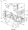
- FIG. 2A illustrates a front isometric view of the connecting module 114 and FIG. 2B illustrates a rear isometric view of the connecting module 114, according to an embodiment of the present disclosure.
- the connecting module 114 includes a body 202 configured to engage with the server unit 100.
- the term "configured to engage” refers to a structure of the body 202 dimensioned based on the slot 110 defined in the server unit 100.
- the slot 110 may be designed based on dimensions of the connecting module 114.
- the body 202 includes a front side 204 accessible to a user and a rear side 206 (see FIG. 2B ) configured to releasably couple with the server unit 100.
- the rear side 206 of the body 202 includes a plurality of connectors 208 configured to define an ultra-path interconnect configuration and establish a connection between the first set of computing devices 106 and the second set of computing devices 108.
- the first set of computing devices 106 includes two central processing units (CPUs) and the second set of computing devices 108 includes two CPUs.
- the plurality of connectors 208 are configured to communicably engage with the each of the four CPUs to allow data exchange between the four CPUs in random fashion.
- the term "communicably engage” refers to a state where the CPUs can communicate with one another. For instance, with the aid of the connecting module 114 of the present disclosure, a first CPU of the first set of computing devices 108 may communicate with a second CPU of the second set of computing devices. Alternatively, the term “communicably engage” may refer to communication channels established by the connecting module 114 between motherboards of each of the four CPUs.
- a height "H" of the body 202 may be dimensioned to be easy to hold or grasp by the user.
- the body 202 further includes a first interconnect part 210 extending between the front side 204 and the rear side 206 thereof and configured to engage with the first section 102 of the server unit 100.
- the body 202 further includes a second interconnect part 212 extending between the front side 204 and the rear side 206 thereof, configured to engage with the second section 104 of the server unit 100.
- Each of the first interconnect part 210 and the second interconnect part 212 extends along a width "W" of the body 202.
- FIG. 2C illustrates a cross-sectional view of the connecting module 114 considered along a section line A-A' in FIG. 2B .
- the first interconnect part 210 and the second interconnect part 212 are separated by a gap "G" configured to receive a partition plate 214 (shown in FIG. 1 and FIG. 4 ) of the server unit 100.
- the partition plate 214 is located between the first section 102 and the second section 104 of the server unit 100 and may include, but not limited to, the node controller systems and the management systems.
- the connecting module 114 further includes a first lever 216 and a second lever 218.
- the first lever 216 includes a first end 220 pivotally coupled to a first side 222 of the body 202.
- the first end 220 of the first lever 216 is coupled to a surface 224 of the second interconnect part 212 through a pivot pin 226 (also shown in FIG. 2B ).
- the first lever 216 may be deflected and rotated about the pivot pin 226 with respect to the front side 204 of the body 202.
- a second end 230 of the first lever 216 is configured to latch with the front side 204 of the body 202.
- the second end 230 may be latched to the front side 204 of the body 202 via a snap lock, such as a snap 314 (see FIG. 3A and FIG. 3B ).
- the first lever 216 also includes a handle 232 (alternatively referred to as "first handle 232" in the present disclosure) accessible by the user.
- the handle 232 may be ergonomically designed to allow easy access by the user.
- the handle 232 may be provided at the second end 230 so that the user can grasp the handle 232 and then the first lever 216 can be rotated about the pivot pin 226.
- the second lever 218 includes a first end 234 pivotally coupled to a second side 236 of the body 202 through another pivot pin (not shown) located at a position corresponding to the pivot pin 226 on the first side 222.
- the second side 236 is located opposite to the first side 222 of the body 202 along a breadth "B" of the connecting module 114.
- the first lever 216 and the second lever 218 may alternatively be referred to as a right lever and a left lever, respectively.
- a second end 242 of the second lever 218 is configured to latch with the front side 204 of the body 202 via a snap 228.
- the second lever 218 also includes a handle 238 (alternatively referred to as "the second handle 238" in the present disclosure) accessible by the user.
- a latched condition of the first lever 216 and the second lever 218 is illustrated in FIG. 1 , where the second ends of the first lever 216 and the second lever 218 are in flush with the front side 204 of the body 202.
- the connecting module 114 is communicably engaged with the first set of computing devices 106 and the second set of computing devices 108.
- the connecting module 114 also includes an actuator 240 disposed on the front side 204 of the body 202.
- the actuator 240 is configured to allow disengagement of the connecting module 114 from the server unit 100 upon actuation, and to unlatch the second ends of each of the first lever 216 and the second lever 218 from the front side 204 of the body 202.
- each of the first lever 216 and the second lever 218 can be selectively and manually deflected with respect to the first ends thereof to allow travel of the connecting module 114 in a direction inward and outward with respect to the server unit 100.
- a manner in which the actuator 240 aids unlatching of the second ends of each of the first lever 216 and the second lever 218 is described later in the description.
- the body 202, the first lever 216, the second lever 218, and the actuator 240 may be made of one of stainless steel or casted aluminum. As such, in an example embodiment, each of these components may be provided with smooth surface finish to add to the aesthetics of the connecting module 114.
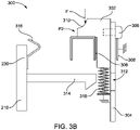
- FIG. 3A and FIG. 3B illustrates a lever locking mechanism 300 of the connecting module 114 and will be described in conjunction with FIG. 1 to FIG. 2B .
- the actuator 240 is made accessible to the user.
- the actuator 240 includes a push button 302 configured to slide between a first position "P1" and a second position "P2" along the front side 204 of the body 202.
- FIG. 3A depicts the first position "P1" of the push button 302 and the FIG. 3B depicts the second position "P2" of the push button 302.
- the push button 302 is fastened to a slider 304 via a fastener 306 and the slider 304 extends along the front side 204 of the body 202.
- the push button 302 and the slider 304 are together movably disposed between guide members 308 in the body 202.
- the guide members 308 allow for a linear movement of the push button 302 and the slider 304.
- An arcuate surface 310 of the push button 302 is provided to receive a push force "F" via a finger of the user, where the push force "F” causes the linear movement of the push button 302 along the front side 204 of the body 202.
- the slider 304 defines two openings to receive the snaps of the first lever 216 and the second lever 218.
- one opening is defined in the slider 304 on each side of the push button 302.
- FIG. 3A and FIG. 3B depicts working of the lever locking mechanism 300 with respect to the push button 302 and the first lever 216.
- the snap 314 of the first lever 216 engages with a first opening 312 defined in the slider 304.
- the snap 314 of the first lever 216 is secured against the slider 304, thereby retaining the first lever 216 latched to the front side 204 of the body 202.
- the connecting module 114 includes a first leaf spring 316, where one end of the first leaf spring 316 is attached to the second end 230 of the first lever 216 and a free end of the first leaf spring 316 is located against the front side 204 of the body 202 when the first lever 216 is latched to the body 202. As such, in the first position "P1" of the push button 302, the first lever 216 remains latched with the body 202 against a biasing force of the first leaf spring 316.
- the lever locking mechanism 300 also includes a biasing member 318, for example, a spring, located along the front side 204 of the body 202 and coupled to the push button 302.
- the biasing member 318 is configured to retain the actuator 240 in the first position "P1" corresponding to a normal state thereof the biasing member 318 and apply a biasing force on the actuator 240 in the second position "P2" corresponding to a biased state thereof.
- the term "normal state” refers to a free length condition of the biasing member 318 where no force is incident on the biasing member 318
- biassed state refers to a compressed length condition of the biasing member 318 where the push force "F” is incident on the biasing member 318.
- the push button 302 Upon application of the push force "F" by the user, the push button 302 is actuated towards the second position "P2". Accordingly, the push button 302 and the slider 304 are caused to move along the front side 204 of the body 202 and against the biasing force of the biasing member 318, thereby compressing the biasing member 318 as shown in FIG. 3B . Due to the movement of the slider 304, the snap 314 is released from the slider 304 through the first opening 312. As such, in the second position "P2" of the push button 302, the first lever 216 is unlatched from the front side 204 of the body 202.
- the first lever 216 is forced to move in a direction outward with respect to the server unit 100.
- Such outward movement of the first lever 216 further allows disengagement of the connecting module 114 from the server unit 100.
- the second ends of each of the first lever 216 and the second lever 218 remains latched to the front side 204 of the body 202 in the normal state of the biasing member 318 corresponding to the first position "P1" of the push button 302 and is unlatched from the front side 204 of the body 202 in the biased state of the biasing member 318 corresponding to the second position "P2" of the push button 302.
- the actuator 240 is configured to allow disengagement of the connecting module 114 from the first set of computing devices 106 and the second set of computing devices 108 upon actuation.
- the connecting module 114 further includes a second leaf spring configured to apply a biasing force on the second lever 218 in a latched condition of the second lever 218.
- the push button 302 and the slider 304 may be provided as a single component configured to slide in the direction of application of push force "F" and unlatch each of the first lever 216 and the second lever 218 from the front side 204 of the body 202.
- FIG. 4 illustrates a cross-sectional view of the server unit 100 showing unlatched condition of the first lever 216 and the second lever 218 of the connecting module 114.
- the partition plate 214 includes a first stopper 402 and the first lever 216 includes a first arm 404 defining a first cut-out 406.
- the end of the first arm 404 defining the first cut-out 406 is pivotally coupled to the first interconnect part 210 (not shown in FIG. 4 ) on the first side 222 of the body 202 via a first pivot member 408.
- the first pivot member 408 may be embodied similar to the pivot pin 226.
- a profile of the first cut-out 406 is configured to pivotally engage with the first stopper 402.
- the connecting module 114 also includes a first support member 418 to retain the first cut-out 406 pivotally engaged with the first stopper 402.
- a combined effect of manual deflection of the first lever 216 and the pivotal engagement between the profile of the first cut-out 406 and the first stopper 402 allows travel of the connecting module 114 in the direction inward and outward with respect to the server unit 100 upon deflection of the first lever 216 after being unlatched from the front side 204 of the body 202.
- the partition plate 214 also includes a second stopper 410 and the second lever 218 includes a second arm 412 defining a second cut-out 414.
- An end of the second arm 412 defining the second cut-out 414 is pivotally coupled to the first interconnect part 210 (not shown in FIG. 4 ) on the second side 236 of the body 202 via a second pivot member 416.
- the second pivot member 416 may be embodied similar to the pivot pin 226.
- a profile of the second cut-out 414 is configured to pivotally engage with the second stopper 410.
- the connecting module 114 also includes a second support member 420 to retain the second cut-out 414 pivotally engaged with the second stopper 410.
- a combined effect of manual deflection of the second lever 218 and the pivotal engagement between the profile of the second cut-out 414 and the second stopper 410 allows the travel of the connecting module 114 in the direction inward and outward with respect to the server unit 100 upon deflection of the second lever 218 after being unlatched from the front side 204 of the body 202. It will be understood that the first lever 216 and the second lever 218 need to be simultaneously deflected by the user to cause the travel of the connecting module 114 in the direction inward and outward with respect to the server unit 100. Additionally, profiles of the first cut-out 406 and the second cut-out 414 are for illustration purpose only and should not be considered as limiting.
- first support member 418 and the second support member 420 may be provided in the partition plate 214.
- Each of the first support member 418 and the second support member 420 are provided to restrict the manual deflection of the first lever 216 and the second lever 218, respectively, while ejecting the connecting module 114 from the server unit 100.
- FIG. 5 illustrates a schematic view of a travel mechanism of the connecting module 114 according to an exemplary embodiment of the present disclosure.
- each of the first stopper 402 and the second stopper 410 are fixed to the partition plate 214.
- the travel mechanism of the connecting module 114 is described with respect to the first arm 404 and the first stopper 402.
- the first pivot member 408 and the first stopper 402 are offset by a distance "D".
- the first lever 216 is selectively and manually deflected (also referred to as "rotated"), a surface "S" of the first cut-out 406 remains in contact with the first stopper 402.
- the connecting module 114 is received within the slot 110 and hence restricted in degree of freedom of movement. With such arrangement, a rotational movement of the first arm 404 is translated to linear movement of the connecting module 114. Therefore, manual rotation of the first lever allows travel of the connecting module 114 in the direction outward with respect to the server unit 100 or in a direction inward with respect to the surface "S".
- the manual and simultaneous rotation of the first lever 216 and the second lever 218 may achieve a travel distance of the connecting module 114 in a range of about 2.5 mm to about 4 mm.
- each of the first lever 216 and the second lever 218 are configured to pivotally deflect about respective first ends thereof with a covered angle ( ⁇ ) in a range of about 30 degrees to about 50 degrees.
- each of the first lever 216 and the second lever 218 are configured to pivotally deflect about respective first ends thereof with the covered angle ( ⁇ ) in a range of about 35 degrees to about 45 degrees.
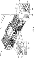
- FIG. 6A illustrates an isometric view of the server unit 100 showing the connecting module 114 being disengaged from the server unit 100 and FIG. 6B shows the connecting module 114 completely disengaged from the server unit 100.
- FIG. 6A and FIG. 6B will be described in conjunction with FIG. 1 through FIG. 5 .
- the user may actuate the actuator 240 by applying the push force "F" on the push button 302.
- the application of the push force "F” causes the push button 302 and the slider 304 to move along the front side 204 of the body 202 in the direction of an application of the push force "F”, thereby unlatching the first lever 216 and the second lever 218 from the front side 204 of the body 202.
- the unlatching of the first lever 216 and the second lever 218 allows the user to access respective handles.
- the user may simultaneously rotate each of the first lever 216 and the second lever 218 in a direction outward with respect to the front side 204 of the body 202.
- Such rotation of the first lever 216 and the second lever 218 causes the first arm 404 and the second arm 412 to pivot about the first stopper 402 and the second stopper 410, respectively, thereby resulting in outward travel of the connecting module 114 with respect to the server unit 100.
- the user may then grasp the connecting module 114 in hand and pull the connecting module 114 in the direction further outward to completely disengage the connecting module 114 from the server unit 100.
- periphery of the slot 110 in the server unit 100 may be made smooth to reduce development of friction while the connecting module 114 is being unplugged.
- the user may align the connecting module 114 with the slot 110 in the server unit 100.
- the user may then gradually insert the connecting module 114 into the slot 110.
- the first stopper 402 and the second stopper 410 guides the first arm 404 and the second arm 412, such that the first cut-out 406 engages with the first stopper 402 and the second cut-out 414 engages with the second stopper 410.
- a surface opposite to the surface "S" of the first cut-out 406 contacts the first stopper 402 to auto-engage the surface "S" with the first stopper 402 during the insertion of the connecting module 114 into the slot 110.
- corresponding surfaces of the second cut-out 414 engages with the second stopper 410.
- Further inward push of the connecting module 114 causes the first lever 216 and the second lever 218 to gradually rotate in the direction towards the front side 204 of the body 202.
- the user may then hold the handles of the first lever 216 and the second lever 218 and rotate the first lever 216 and the second lever 218 simultaneously inward with respect to the server unit 100 until each of the first lever 216 and the second lever 218 latches with the front side 204 of the body 202.
- the connecting module 114 remains communicably engaged with the first set of computing devices 106 and the second set of computing devices 108.
- the connecting module 114 may include a single lever configured to unlatch the connecting module 114 from the server unit 100. To this end, the connecting module 114 may be plugged to the server unit 100 and unplugged from the server unit 100 without need of any external tools. Therefore, the present disclosure provides a tool-less connecting module 114. Since the first lever 216 and the second lever 218 are integral to the connecting module 114 and aid in engaging the UPI module 114 into the slot 110 of the server unit 100, any requirement of fasteners, such as captive screws, may be overcome. As such, a time required to unplug and plug the connecting module 114 with respect to the server unit 100 may be largely reduced.
- the connecting module 114 Since ejection of the connecting module 114 includes only two steps, namely, actuation of the actuator 240 and the simultaneous rotation of the first lever 216 and the second lever 218, effort to be invested by the user is substantially reduced compared to the conventional methods. Additionally, since the actuation of the actuator 240 is achieved by a single finger, ejection process is rendered simple. Therefore, the connecting module 114 of the present disclosure aligns with the requirements of a customer replaceable unit (CRU).
- CRU customer replaceable unit
- the lever locking mechanism 300 described with respect to FIG. 3A and FIG. 3B , and the travel mechanism described with respect to FIG. 5 may be implemented with respect to other components of the server unit 100.
- the lever locking mechanism 300 may be implemented for drawers of the server unit 100.
- a single lever may be implemented in a drawer (for example, a tray) in the server unit 100 for linearly moving the drawer inward and outward with respect to the server unit 100.
- the drawer may be configured to accommodate multiple components of the server unit 100, for example, cooling modules.
- the lever locking mechanism 300 may be implemented in handles of the server unit 100 to engage rear connectors of motherboard with rear connecting module.
- the lever locking mechanism 300 may be provided in rear input-output (I/O) modules.
- the connecting module 114 may be implemented in, for example, but not limited to, scalable memory devices, scalable storage devices, central processing units (CPUs), accelerators, switches and routers.
- CPUs central processing units
- switches switches and routers.
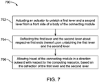
- FIG. 7 shows a flowchart of a method 700 for disengaging the connecting module 114 from the computing resource 100.
- the method 700 includes actuating the actuator 240 to unlatch the first lever 216 and the second lever 218 from the front side 204 of the body 202 of the connecting module 114.
- the method 700 includes deflecting the first lever 216 and the second lever 218 about respective first ends 220, 234 thereof upon unlatching the first lever 216 and the second lever 218.
- each of the first lever 216 and the second lever 218 is configured to pivotally deflect about respective first ends 220, 234 thereof with a covered angle ( ⁇ ) in a range of about 30 degrees to about 50 degrees.
- the method 700 includes allowing travel of the connecting module 114 in the direction outward with respect to the computing resource 100, based on the deflection of the first lever 216 and the second lever 218.
- the method 700 further includes sliding the push button 302 between the first position "P1" and the second position "P2" along the front side 204 of the body 202, against the biasing force of the biasing member 318, to unlatch the first lever 216 and the second lever 218 from the front side 204 of the body 202.
- the method 700 further includes pivotally engaging the profile of the first cut-out 406 with the first stopper 402, where the first cut-out 406 is defined in the first arm 404 of the first lever 216 and the first stopper 402 is located on the partition plate 214 of the computing resource 100.
- the method 700 also includes pivotally engaging the profile of the second cut-out 414 with a second stopper 410, where the second cut-out 414 is defined in the second arm 412 of the second lever 218 and the second stopper 410 is located on the partition plate 214 of the computing resource 100.
Landscapes
- Engineering & Computer Science (AREA)
- Microelectronics & Electronic Packaging (AREA)
- Computer Hardware Design (AREA)
- General Engineering & Computer Science (AREA)
- Theoretical Computer Science (AREA)
- Power Engineering (AREA)
- Human Computer Interaction (AREA)
- Physics & Mathematics (AREA)
- General Physics & Mathematics (AREA)
- Lock And Its Accessories (AREA)
- Details Of Connecting Devices For Male And Female Coupling (AREA)
Abstract
Description
- The present disclosure relates, in general, to a computing resource and, more specifically relates, to a connecting module for the computing resource.
- High performance computing of resources, such as servers, has gained importance in recent years by several industries which are trending towards increasing sizes or combinations of two or more servers to achieve faster processing performance for a large number of processing operations. Solutions known to address such requirement of the industries include Ultra Path Interconnect (UPI) technology which provides a scalable multiprocessor system, for example, by linking motherboards of two or more computing resources together. However, users face several issues in the servers which either require a maintenance activity to be carried out on the servers and may often include replacement of few components in the servers.
- Currently, in order to remove a connecting module, for example, a scalable UPI module, from the server and/or to replace a faulty Dual In-Line Memory Module (DIMM) in the server, users must invest a large amount of time by using multiple tools, which renders replacement activity complex. Conventionally, the scalable UPI module is secured to the server unit with multiple captive screws. As such, users may need to spend more time to disengage and engage the scalable UPI module from the server. Additionally, such scenarios of using multiple tools demand knowledge of use of such tools to prevent any damage to the scalable module or the server unit. As such, user ergonomics and convenience may be affected, thereby violating principles of customer replaceable unit (CRU).
- Accordingly, it is one object of the present disclosure to provide a user-friendly connecting module which reduces effort and time to be invested by the user to install or remove the connecting module from computing resources.
- According to one aspect of the present disclosure, a connecting module is disclosed. The connecting module includes a body configured to engage with a computing resource, where a front side of the body is accessible to a user and a rear side is configured to releasably couple with the computing resource. In an embodiment, the computing resource is implemented as a server unit. The rear side of the body includes a plurality of connectors configured to connect with computing devices of the computing resource. The connecting module further includes a first lever comprising a first end pivotally coupled to a first side of the body and a second end configured to latch with the front side of the body, and a second lever comprising a first end pivotally coupled to a second side of the body and a second end configured to latch with the front side of the body, where the second side of the body is opposite to the first side of the body. The connecting module also includes an actuator disposed on the front side of the body. The actuator is configured to allow disengagement of the connecting module from the computing resource upon actuation and configured to unlatch the second ends of each of the first lever and the second lever from the front side of the body. Advantageously, each of the first lever and the second lever are selectively and manually deflectable about respective first ends thereof to allow travel of the connecting module in a direction inward and outward with respect to the computing resource.
- In an embodiment, each of the first lever and the second lever are configured to pivotally deflect about respective first ends thereof with a covered angle in a range of about 30 degrees to about 50 degrees.
- In another embodiment, the covered angle may be in a range of covered angle in a range of about 35 degrees to about 45 degrees.
- In an embodiment, the selective and manual deflection of the first lever and the second lever may achieve travel of the connecting module in a range of about 2.5 mm to about 4 mm.
- In an embodiment, the actuator includes a push button configured to slide between a first position and a second position along the front side of the body and a biasing member coupled to the push button. The biasing member is configured to retain the actuator in the first position corresponding to a normal state of the biasing member and to apply a biasing force on the actuator in the second position corresponding to a biased state of the biasing member. The second ends of each of the first lever and the second lever remain latched to the front side of the body in the normal state of the biasing member and unlatched from the front side of the body in the biased state of the biasing member. In an embodiment, the first lever and the second lever are latched to the front side of the body via a snap lock. In an embodiment, the connecting module further includes a first leaf spring to apply a biasing force on the first lever in a latched condition of the first lever and a second leaf spring to apply a biasing force on the second lever in a latched condition of the second lever.
- The body of the connecting module further includes a first interconnect part to engage with a first section of the computing resource and a second interconnect part configured to engage with a second section of the computing resource. The first section includes a first set of computing devices and the second section includes a second set of computing devices. Each of the first interconnect part and the second interconnect part extends from the front side of the body along a width thereof. In an embodiment, the first interconnect part and the second interconnect part are separated by a gap configured to receive a partition plate of the computing resource, where the partition plate is located between the first section of the computing resource and the second section of the computing resource.
- In an embodiment, the partition plate includes a first stopper, and the first lever includes a first arm defining a first cut-out. A profile of the first cut-out is configured to pivotally engage with the first stopper, such that pivotal engagement between the profile of the first cut-out and the first stopper allows the travel of the connecting module in the direction inward and outward with respect to the computing resource upon deflection of the first lever. The partition plate further includes a second stopper, and the second lever includes a second arm defining a second cut-out. A profile of the second cut-out is configured to pivotally engage with the second stopper, such that the pivotal engagement between the profile of the second cut-out and the second stopper allows the travel of the connecting module in the direction inward and outward with respect to the computing resource upon deflection of the second lever. In an implementation, the connecting module may be embodied as a front UPI module.
- According to another aspect of the present disclosure, a method for disengaging a connecting module from a computing resource is disclosed. In an embodiment, the method includes actuating an actuator to unlatch a first lever and a second lever from a front side of a body of the connecting module. The method further includes deflecting the first lever and the second lever about respective first ends thereof upon unlatching the first lever and the second lever. The method also includes allowing travel of the connecting module in a direction outward with respect to the computing resource, based on the deflection of the first lever and the second lever.
- In an embodiment, the method includes pivotally engaging a profile of a first cut-out with a first stopper. The first cut-out is defined in a first arm of the first lever and the first stopper is located on a partition plate of the computing resource.
- In an embodiment, the method includes pivotally engaging a profile of a second cut-out with a second stopper. The second cut-out is defined in a second arm of the second lever and the second stopper is located on the partition plate of the computing resource.
- Other aspects and advantages of non-limiting embodiments of the present disclosure will become apparent to those skilled in the art upon review of the following description of specific non-limiting embodiments of the disclosure in conjunction with the accompanying drawings.
- A better understanding of embodiments of the present disclosure (including alternatives and/or variations thereof) may be obtained with reference to the detailed description of the embodiments along with the following drawings, in which:
-
FIG. 1 is an isometric view of a computing resource including a connecting module, according to an embodiment of the present disclosure; -
FIG. 2A is a front isometric view of the connecting module, according to an embodiment of the present disclosure; -
FIG. 2B is a rear isometric view of the connecting module, according to an embodiment of the present disclosure; -
FIG. 2C is a cross-sectional view of the connecting module considered along a section A-A' inFIG. 2B , according to an embodiment of the present disclosure; -
FIG. 3A is a lever locking mechanism of the connecting module showing a first position of an actuator of the lever locking mechanism, according to an embodiment of the present disclosure; -
FIG. 3B is the lever locking mechanism of the connecting module showing a second position of the actuator of the lever locking mechanism, according to an embodiment of the present disclosure; -
FIG. 4 is a cross-sectional view of the computing resource showing unlatched levers of the connecting module, according to an embodiment of the present disclosure; -
FIG. 5 is a schematic view of a travel mechanism of the connecting module, according to an exemplary embodiment of the present disclosure; -
FIG. 6A is an isometric view of the computing resource showing the connecting module being disengaged from the computing resource, according to an embodiment of the present disclosure; -
FIG. 6B is an isometric view of the computing resource showing the connecting module completely disengaged from the computing resource, according to an embodiment of the present disclosure; and -
FIG. 7 is a flowchart of a method for disengaging a connecting module from a computing resource, according to an embodiment of the present disclosure. - Reference will now be made in detail to specific embodiments or features, examples of which are illustrated in the accompanying drawings. Wherever possible, corresponding or similar reference numbers will be used throughout the drawings to refer to the same or corresponding parts. Moreover, references to various elements described herein are made collectively or individually when there may be more than one element of the same type. However, such references are merely exemplary in nature. It may be noted that any reference to elements in the singular may also be construed to relate to the plural and vice-versa without limiting the scope of the disclosure to the exact number or type of such elements unless set forth explicitly in the appended claims.
- Aspects of the present disclosure are directed to a computing resource, such as a server unit, implementing a connecting module capable of being disposed into a slot defined in the computing resource using minimum human effort. The connecting module includes levers capable of being pivotably deflected by a user to allow detachment of the connecting module from the computing resource. Likewise, the levers also enable the user to dispose the connecting module back into the slot of the computing resource. The connecting module eliminates use of any external tools to engage and disengage the connecting module from the computing resource.
- Referring to
FIG. 1 , an isometric view of acomputing resource 100 is illustrated. According to an aspect of the present disclosure, thecomputing resource 100 is implemented as the server unit, and hence the term "computing resource 100" is alternatively referred to as "theserver unit 100". Theserver unit 100 includes afirst section 102 and asecond section 104, where thefirst section 102 includes a first set ofcomputing devices 106 and thesecond section 104 includes a second set ofcomputing devices 108. As used herein, the term "computing devices" may include, but are not limited to, motherboards, multiple processors, random-access-memory (RAM), dual in-line memory modules (DIMMs) and multiple sockets to aid connection with the processors. It will be apparent to a person skilled in the art that theserver unit 100 may be housed in a server rack (not shown) that is configured to accommodate multiple server units, switches, cords and cables, rails, cable management bars, routers, path panels, and blanking panels. For example, theserver unit 100 may be a part of a scalable server infrastructure implementing customized high-performance computing systems. Although not explicitly shown, it will be understood that theserver unit 100 may include, but is not limited to, motherboards, hard drives, network ports, one or more node controller systems, management systems, and power cables. - According to an embodiment of the present disclosure, the
first section 102 and thesecond section 104 together defines a slot 110 (seeFIG. 6B ) at afront portion 112 thereof. Theserver unit 100 further includes a connectingmodule 114 configured to releasably dispose in theslot 110. The connectingmodule 114 is embodied as a front ultra-path interconnect (UPI) module in the present disclosure. Since the connectingmodule 114 is connected with theserver unit 100 at thefront portion 112, the connectingmodule 114 is alternatively referred to as the "front connectingmodule 114". Provision of the front connectingmodule 114 adds to available space in theserver unit 100, thereby allowing additional components to be accommodated to enhance functionality of theserver unit 100 as per user's requirement. Further, the connectingmodule 114 overcomes requirement of any external tools and fasteners for coupling with theserver unit 100. In some implementations, theserver unit 100 may also include a rear connecting module (not shown). The connectingmodule 114 is considered as a customer replaceable unit (CRU) that can be removed and replaced by users. -
FIG. 2A illustrates a front isometric view of the connectingmodule 114 andFIG. 2B illustrates a rear isometric view of the connectingmodule 114, according to an embodiment of the present disclosure. The connectingmodule 114 includes abody 202 configured to engage with theserver unit 100. As used herein, the term "configured to engage" refers to a structure of thebody 202 dimensioned based on theslot 110 defined in theserver unit 100. However, in some implementations, theslot 110 may be designed based on dimensions of the connectingmodule 114. Thebody 202 includes afront side 204 accessible to a user and a rear side 206 (seeFIG. 2B ) configured to releasably couple with theserver unit 100. In an implementation, therear side 206 of thebody 202 includes a plurality ofconnectors 208 configured to define an ultra-path interconnect configuration and establish a connection between the first set ofcomputing devices 106 and the second set ofcomputing devices 108. In an implementation, the first set ofcomputing devices 106 includes two central processing units (CPUs) and the second set ofcomputing devices 108 includes two CPUs. - The plurality of
connectors 208, specifically four (4) socket connectors according to a preferred embodiment of the present disclosure, are configured to communicably engage with the each of the four CPUs to allow data exchange between the four CPUs in random fashion. The term "communicably engage" refers to a state where the CPUs can communicate with one another. For instance, with the aid of the connectingmodule 114 of the present disclosure, a first CPU of the first set ofcomputing devices 108 may communicate with a second CPU of the second set of computing devices. Alternatively, the term "communicably engage" may refer to communication channels established by the connectingmodule 114 between motherboards of each of the four CPUs. - In an embodiment, a height "H" of the
body 202 may be dimensioned to be easy to hold or grasp by the user. Thebody 202 further includes afirst interconnect part 210 extending between thefront side 204 and therear side 206 thereof and configured to engage with thefirst section 102 of theserver unit 100. Thebody 202 further includes asecond interconnect part 212 extending between thefront side 204 and therear side 206 thereof, configured to engage with thesecond section 104 of theserver unit 100. Each of thefirst interconnect part 210 and thesecond interconnect part 212 extends along a width "W" of thebody 202. -
FIG. 2C illustrates a cross-sectional view of the connectingmodule 114 considered along a section line A-A' inFIG. 2B . In an embodiment, thefirst interconnect part 210 and thesecond interconnect part 212 are separated by a gap "G" configured to receive a partition plate 214 (shown inFIG. 1 andFIG. 4 ) of theserver unit 100. Thepartition plate 214 is located between thefirst section 102 and thesecond section 104 of theserver unit 100 and may include, but not limited to, the node controller systems and the management systems. - Referring to
FIG. 2A , the connectingmodule 114 further includes afirst lever 216 and asecond lever 218. Thefirst lever 216 includes afirst end 220 pivotally coupled to afirst side 222 of thebody 202. As can be seen inFIG. 2A , thefirst end 220 of thefirst lever 216 is coupled to asurface 224 of thesecond interconnect part 212 through a pivot pin 226 (also shown inFIG. 2B ). With the aid of thepivot pin 226, thefirst lever 216 may be deflected and rotated about thepivot pin 226 with respect to thefront side 204 of thebody 202. Further, asecond end 230 of thefirst lever 216 is configured to latch with thefront side 204 of thebody 202. In an embodiment, thesecond end 230 may be latched to thefront side 204 of thebody 202 via a snap lock, such as a snap 314 (seeFIG. 3A andFIG. 3B ). - In an embodiment, the
first lever 216 also includes a handle 232 (alternatively referred to as "first handle 232" in the present disclosure) accessible by the user. In an example, thehandle 232 may be ergonomically designed to allow easy access by the user. For example, thehandle 232 may be provided at thesecond end 230 so that the user can grasp thehandle 232 and then thefirst lever 216 can be rotated about thepivot pin 226. - Similarly, the
second lever 218 includes afirst end 234 pivotally coupled to asecond side 236 of thebody 202 through another pivot pin (not shown) located at a position corresponding to thepivot pin 226 on thefirst side 222. Thesecond side 236 is located opposite to thefirst side 222 of thebody 202 along a breadth "B" of the connectingmodule 114. With reference to the user facing theserver unit 100, thefirst lever 216 and thesecond lever 218 may alternatively be referred to as a right lever and a left lever, respectively. Further, asecond end 242 of thesecond lever 218 is configured to latch with thefront side 204 of thebody 202 via asnap 228. Thesecond lever 218 also includes a handle 238 (alternatively referred to as "thesecond handle 238" in the present disclosure) accessible by the user. A latched condition of thefirst lever 216 and thesecond lever 218 is illustrated inFIG. 1 , where the second ends of thefirst lever 216 and thesecond lever 218 are in flush with thefront side 204 of thebody 202. Additionally, in the latched condition of thefirst lever 216 and thesecond lever 218, the connectingmodule 114 is communicably engaged with the first set ofcomputing devices 106 and the second set ofcomputing devices 108. - In an embodiment, the connecting
module 114 also includes anactuator 240 disposed on thefront side 204 of thebody 202. Theactuator 240 is configured to allow disengagement of the connectingmodule 114 from theserver unit 100 upon actuation, and to unlatch the second ends of each of thefirst lever 216 and thesecond lever 218 from thefront side 204 of thebody 202. Upon being unlatched, each of thefirst lever 216 and thesecond lever 218 can be selectively and manually deflected with respect to the first ends thereof to allow travel of the connectingmodule 114 in a direction inward and outward with respect to theserver unit 100. A manner in which theactuator 240 aids unlatching of the second ends of each of thefirst lever 216 and thesecond lever 218 is described later in the description. In some implementations, thebody 202, thefirst lever 216, thesecond lever 218, and theactuator 240 may be made of one of stainless steel or casted aluminum. As such, in an example embodiment, each of these components may be provided with smooth surface finish to add to the aesthetics of the connectingmodule 114. -
FIG. 3A andFIG. 3B illustrates alever locking mechanism 300 of the connectingmodule 114 and will be described in conjunction withFIG. 1 to FIG. 2B . By providing theactuator 240 on thefront side 204 of thebody 202, theactuator 240 is made accessible to the user. In an implementation, theactuator 240 includes apush button 302 configured to slide between a first position "P1" and a second position "P2" along thefront side 204 of thebody 202. For example,FIG. 3A depicts the first position "P1" of thepush button 302 and theFIG. 3B depicts the second position "P2" of thepush button 302. - In an embodiment, the
push button 302 is fastened to aslider 304 via afastener 306 and theslider 304 extends along thefront side 204 of thebody 202. Thepush button 302 and theslider 304 are together movably disposed betweenguide members 308 in thebody 202. As can be seen fromFIG. 3A andFIG. 3B , theguide members 308 allow for a linear movement of thepush button 302 and theslider 304. Anarcuate surface 310 of thepush button 302 is provided to receive a push force "F" via a finger of the user, where the push force "F" causes the linear movement of thepush button 302 along thefront side 204 of thebody 202. Further, theslider 304 defines two openings to receive the snaps of thefirst lever 216 and thesecond lever 218. For example, one opening is defined in theslider 304 on each side of thepush button 302. For the purpose of brevity,FIG. 3A andFIG. 3B depicts working of thelever locking mechanism 300 with respect to thepush button 302 and thefirst lever 216. Accordingly, thesnap 314 of thefirst lever 216 engages with afirst opening 312 defined in theslider 304. In the first position "P1" of thepush button 302, thesnap 314 of thefirst lever 216 is secured against theslider 304, thereby retaining thefirst lever 216 latched to thefront side 204 of thebody 202. - In an embodiment, the connecting
module 114 includes afirst leaf spring 316, where one end of thefirst leaf spring 316 is attached to thesecond end 230 of thefirst lever 216 and a free end of thefirst leaf spring 316 is located against thefront side 204 of thebody 202 when thefirst lever 216 is latched to thebody 202. As such, in the first position "P1" of thepush button 302, thefirst lever 216 remains latched with thebody 202 against a biasing force of thefirst leaf spring 316. - The
lever locking mechanism 300 also includes a biasingmember 318, for example, a spring, located along thefront side 204 of thebody 202 and coupled to thepush button 302. The biasingmember 318 is configured to retain theactuator 240 in the first position "P1" corresponding to a normal state thereof the biasingmember 318 and apply a biasing force on theactuator 240 in the second position "P2" corresponding to a biased state thereof. As used herein, the term "normal state" refers to a free length condition of the biasingmember 318 where no force is incident on the biasingmember 318, and the term "biased state" refers to a compressed length condition of the biasingmember 318 where the push force "F" is incident on the biasingmember 318. - Upon application of the push force "F" by the user, the
push button 302 is actuated towards the second position "P2". Accordingly, thepush button 302 and theslider 304 are caused to move along thefront side 204 of thebody 202 and against the biasing force of the biasingmember 318, thereby compressing the biasingmember 318 as shown inFIG. 3B . Due to the movement of theslider 304, thesnap 314 is released from theslider 304 through thefirst opening 312. As such, in the second position "P2" of thepush button 302, thefirst lever 216 is unlatched from thefront side 204 of thebody 202. Simultaneously, by virtue of the biasing force of thefirst leaf spring 316, thefirst lever 216 is forced to move in a direction outward with respect to theserver unit 100. Such outward movement of thefirst lever 216 further allows disengagement of the connectingmodule 114 from theserver unit 100. To this end, it is understood that the second ends of each of thefirst lever 216 and thesecond lever 218 remains latched to thefront side 204 of thebody 202 in the normal state of the biasingmember 318 corresponding to the first position "P1" of thepush button 302 and is unlatched from thefront side 204 of thebody 202 in the biased state of the biasingmember 318 corresponding to the second position "P2" of thepush button 302. Therefore, besides unlatching thefirst lever 216 and thesecond lever 218 from thefront side 204 of thebody 202, theactuator 240 is configured to allow disengagement of the connectingmodule 114 from the first set ofcomputing devices 106 and the second set ofcomputing devices 108 upon actuation. - Soon after the user removes the finger from the
arcuate surface 310 of thepush button 302 and the push forces "F" ceases to act on thepush button 302, by virtue of the biasing force of the biasingmember 318, thepush button 302 is forced to the first position "P1". Although not illustrated, the connectingmodule 114 further includes a second leaf spring configured to apply a biasing force on thesecond lever 218 in a latched condition of thesecond lever 218. - In some implementations, the
push button 302 and theslider 304 may be provided as a single component configured to slide in the direction of application of push force "F" and unlatch each of thefirst lever 216 and thesecond lever 218 from thefront side 204 of thebody 202. -
FIG. 4 illustrates a cross-sectional view of theserver unit 100 showing unlatched condition of thefirst lever 216 and thesecond lever 218 of the connectingmodule 114. In an embodiment, thepartition plate 214 includes afirst stopper 402 and thefirst lever 216 includes afirst arm 404 defining a first cut-out 406. The end of thefirst arm 404 defining the first cut-out 406 is pivotally coupled to the first interconnect part 210 (not shown inFIG. 4 ) on thefirst side 222 of thebody 202 via afirst pivot member 408. In one example, thefirst pivot member 408 may be embodied similar to thepivot pin 226. As such, a profile of the first cut-out 406 is configured to pivotally engage with thefirst stopper 402. The connectingmodule 114 also includes afirst support member 418 to retain the first cut-out 406 pivotally engaged with thefirst stopper 402. A combined effect of manual deflection of thefirst lever 216 and the pivotal engagement between the profile of the first cut-out 406 and thefirst stopper 402 allows travel of the connectingmodule 114 in the direction inward and outward with respect to theserver unit 100 upon deflection of thefirst lever 216 after being unlatched from thefront side 204 of thebody 202. - The
partition plate 214 also includes asecond stopper 410 and thesecond lever 218 includes asecond arm 412 defining a second cut-out 414. An end of thesecond arm 412 defining the second cut-out 414 is pivotally coupled to the first interconnect part 210 (not shown inFIG. 4 ) on thesecond side 236 of thebody 202 via asecond pivot member 416. In one example, thesecond pivot member 416 may be embodied similar to thepivot pin 226. In an embodiment, a profile of the second cut-out 414 is configured to pivotally engage with thesecond stopper 410. The connectingmodule 114 also includes asecond support member 420 to retain the second cut-out 414 pivotally engaged with thesecond stopper 410. A combined effect of manual deflection of thesecond lever 218 and the pivotal engagement between the profile of the second cut-out 414 and thesecond stopper 410 allows the travel of the connectingmodule 114 in the direction inward and outward with respect to theserver unit 100 upon deflection of thesecond lever 218 after being unlatched from thefront side 204 of thebody 202. It will be understood that thefirst lever 216 and thesecond lever 218 need to be simultaneously deflected by the user to cause the travel of the connectingmodule 114 in the direction inward and outward with respect to theserver unit 100. Additionally, profiles of the first cut-out 406 and the second cut-out 414 are for illustration purpose only and should not be considered as limiting. In some implementations, thefirst support member 418 and thesecond support member 420 may be provided in thepartition plate 214. Each of thefirst support member 418 and thesecond support member 420 are provided to restrict the manual deflection of thefirst lever 216 and thesecond lever 218, respectively, while ejecting the connectingmodule 114 from theserver unit 100. -
FIG. 5 illustrates a schematic view of a travel mechanism of the connectingmodule 114 according to an exemplary embodiment of the present disclosure. As seen inFIG. 4 , each of thefirst stopper 402 and thesecond stopper 410 are fixed to thepartition plate 214. For the purpose of brevity, the travel mechanism of the connectingmodule 114 is described with respect to thefirst arm 404 and thefirst stopper 402. As shown, thefirst pivot member 408 and thefirst stopper 402 are offset by a distance "D". When thefirst lever 216 is selectively and manually deflected (also referred to as "rotated"), a surface "S" of the first cut-out 406 remains in contact with thefirst stopper 402. Additionally, the connectingmodule 114 is received within theslot 110 and hence restricted in degree of freedom of movement. With such arrangement, a rotational movement of thefirst arm 404 is translated to linear movement of the connectingmodule 114. Therefore, manual rotation of the first lever allows travel of the connectingmodule 114 in the direction outward with respect to theserver unit 100 or in a direction inward with respect to the surface "S". - In an implementation, the manual and simultaneous rotation of the
first lever 216 and thesecond lever 218 may achieve a travel distance of the connectingmodule 114 in a range of about 2.5 mm to about 4 mm. - In some implementations, each of the
first lever 216 and thesecond lever 218 are configured to pivotally deflect about respective first ends thereof with a covered angle (θ) in a range of about 30 degrees to about 50 degrees. - In some implementations, each of the
first lever 216 and thesecond lever 218 are configured to pivotally deflect about respective first ends thereof with the covered angle (θ) in a range of about 35 degrees to about 45 degrees. -
FIG. 6A illustrates an isometric view of theserver unit 100 showing the connectingmodule 114 being disengaged from theserver unit 100 andFIG. 6B shows the connectingmodule 114 completely disengaged from theserver unit 100.FIG. 6A andFIG. 6B will be described in conjunction withFIG. 1 through FIG. 5 . In order to disengage or unplug the connectingmodule 114 from theserver unit 100, the user may actuate theactuator 240 by applying the push force "F" on thepush button 302. The application of the push force "F" causes thepush button 302 and theslider 304 to move along thefront side 204 of thebody 202 in the direction of an application of the push force "F", thereby unlatching thefirst lever 216 and thesecond lever 218 from thefront side 204 of thebody 202. The unlatching of thefirst lever 216 and thesecond lever 218 allows the user to access respective handles. - Further, the user may simultaneously rotate each of the
first lever 216 and thesecond lever 218 in a direction outward with respect to thefront side 204 of thebody 202. Such rotation of thefirst lever 216 and thesecond lever 218 causes thefirst arm 404 and thesecond arm 412 to pivot about thefirst stopper 402 and thesecond stopper 410, respectively, thereby resulting in outward travel of the connectingmodule 114 with respect to theserver unit 100. The user may then grasp the connectingmodule 114 in hand and pull the connectingmodule 114 in the direction further outward to completely disengage the connectingmodule 114 from theserver unit 100. In some implementations, periphery of theslot 110 in theserver unit 100 may be made smooth to reduce development of friction while the connectingmodule 114 is being unplugged. - In order to plug the connecting
module 114 into theslot 110 of theserver unit 100, the user may align the connectingmodule 114 with theslot 110 in theserver unit 100. The user may then gradually insert the connectingmodule 114 into theslot 110. Thefirst stopper 402 and thesecond stopper 410 guides thefirst arm 404 and thesecond arm 412, such that the first cut-out 406 engages with thefirst stopper 402 and the second cut-out 414 engages with thesecond stopper 410. Particularly, a surface opposite to the surface "S" of the first cut-out 406 contacts thefirst stopper 402 to auto-engage the surface "S" with thefirst stopper 402 during the insertion of the connectingmodule 114 into theslot 110. Simultaneously, corresponding surfaces of the second cut-out 414 engages with thesecond stopper 410. Further inward push of the connectingmodule 114 causes thefirst lever 216 and thesecond lever 218 to gradually rotate in the direction towards thefront side 204 of thebody 202. The user may then hold the handles of thefirst lever 216 and thesecond lever 218 and rotate thefirst lever 216 and thesecond lever 218 simultaneously inward with respect to theserver unit 100 until each of thefirst lever 216 and thesecond lever 218 latches with thefront side 204 of thebody 202. As described earlier, in the latched condition of thefirst lever 216 and thesecond lever 218, the connectingmodule 114 remains communicably engaged with the first set ofcomputing devices 106 and the second set ofcomputing devices 108. - In some implementations, the connecting
module 114 may include a single lever configured to unlatch the connectingmodule 114 from theserver unit 100. To this end, the connectingmodule 114 may be plugged to theserver unit 100 and unplugged from theserver unit 100 without need of any external tools. Therefore, the present disclosure provides a tool-less connectingmodule 114. Since thefirst lever 216 and thesecond lever 218 are integral to the connectingmodule 114 and aid in engaging theUPI module 114 into theslot 110 of theserver unit 100, any requirement of fasteners, such as captive screws, may be overcome. As such, a time required to unplug and plug the connectingmodule 114 with respect to theserver unit 100 may be largely reduced. Since ejection of the connectingmodule 114 includes only two steps, namely, actuation of theactuator 240 and the simultaneous rotation of thefirst lever 216 and thesecond lever 218, effort to be invested by the user is substantially reduced compared to the conventional methods. Additionally, since the actuation of theactuator 240 is achieved by a single finger, ejection process is rendered simple. Therefore, the connectingmodule 114 of the present disclosure aligns with the requirements of a customer replaceable unit (CRU). - In some implementation, the
lever locking mechanism 300 described with respect toFIG. 3A andFIG. 3B , and the travel mechanism described with respect toFIG. 5 may be implemented with respect to other components of theserver unit 100. For example, thelever locking mechanism 300 may be implemented for drawers of theserver unit 100. For example, a single lever may be implemented in a drawer (for example, a tray) in theserver unit 100 for linearly moving the drawer inward and outward with respect to theserver unit 100. The drawer may be configured to accommodate multiple components of theserver unit 100, for example, cooling modules. In some implementations, thelever locking mechanism 300 may be implemented in handles of theserver unit 100 to engage rear connectors of motherboard with rear connecting module. In some implementations, thelever locking mechanism 300 may be provided in rear input-output (I/O) modules. - Although the present disclosure describes the implementation of the connecting
module 114 with respect to theserver unit 100, in some implementation, the connectingmodule 114 may be implemented in, for example, but not limited to, scalable memory devices, scalable storage devices, central processing units (CPUs), accelerators, switches and routers. -
FIG. 7 shows a flowchart of amethod 700 for disengaging the connectingmodule 114 from thecomputing resource 100. Atstep 702, themethod 700 includes actuating theactuator 240 to unlatch thefirst lever 216 and thesecond lever 218 from thefront side 204 of thebody 202 of the connectingmodule 114. - At
step 704, themethod 700 includes deflecting thefirst lever 216 and thesecond lever 218 about respective first ends 220, 234 thereof upon unlatching thefirst lever 216 and thesecond lever 218. In an embodiment, each of thefirst lever 216 and thesecond lever 218 is configured to pivotally deflect about respective first ends 220, 234 thereof with a covered angle (θ) in a range of about 30 degrees to about 50 degrees. - At
step 706, themethod 700 includes allowing travel of the connectingmodule 114 in the direction outward with respect to thecomputing resource 100, based on the deflection of thefirst lever 216 and thesecond lever 218. - Although not particularly shown as steps in
FIG. 7 , themethod 700 further includes sliding thepush button 302 between the first position "P1" and the second position "P2" along thefront side 204 of thebody 202, against the biasing force of the biasingmember 318, to unlatch thefirst lever 216 and thesecond lever 218 from thefront side 204 of thebody 202. - In an embodiment, the
method 700 further includes pivotally engaging the profile of the first cut-out 406 with thefirst stopper 402, where the first cut-out 406 is defined in thefirst arm 404 of thefirst lever 216 and thefirst stopper 402 is located on thepartition plate 214 of thecomputing resource 100. Themethod 700 also includes pivotally engaging the profile of the second cut-out 414 with asecond stopper 410, where the second cut-out 414 is defined in thesecond arm 412 of thesecond lever 218 and thesecond stopper 410 is located on thepartition plate 214 of thecomputing resource 100. - All terminologies used herein are for purposes of describing embodiments and examples and should not be construed as limiting the invention. As used herein, the singular forms "a," "an," and "the" are intended to include the plural forms as well, unless the context clearly indicates otherwise. Furthermore, to the extent that the terms "including," "includes," "having," "has," "with," or variants thereof, are used in either the detailed description and/or the claims, such terms are intended to be inclusive in a manner similar to the term "comprising."
- Unless otherwise defined, all terms (including technical and scientific terms) used herein have the same meaning as commonly understood by the person skilled in the art to which this present disclosure belongs. Furthermore, terms, such as those defined in commonly used dictionaries, should be interpreted as having a meaning that is consistent with their meaning in the context of the relevant art and will not be interpreted in an idealized or overly formal sense unless expressly defined herein.
- While aspects of the present disclosure have been particularly shown and described with reference to the embodiments above, it will be understood by those skilled in the art that various additional embodiments may be contemplated by the modification of the disclosed methods without departing from the spirit and scope of what is disclosed. Such embodiments should be understood to fall within the scope of the present disclosure as determined based upon the claims and any equivalents thereof.
Claims (15)
- A connecting module (114) comprising:a body (202) configured to engage with a computing resource (100), the body (202) comprising a front side (204) accessible to a user and a rear side (206) configured to releasably couple with the computing resource (100);characterized in thata first lever (216) comprising a first end (220) pivotally coupled to a first side (222) of the body (202) and a second end (230) configured to latch with the front side (204) of the body (202);a second lever (218) comprising a first end (234) pivotally coupled to a second side (236) of the body (202) and a second end (242) configured to latch with the front side (204) of the body (202), the second side (236) of the body (202) being opposite to the first side (222) of the body (202); andan actuator (240) disposed on the front side (204) of the body (202) and configured to allow disengagement of the connecting module (114) from the computing resource (100) upon actuation, the actuator (240) further configured to unlatch the second ends (230, 242) of each of the first lever (216) and the second lever (218) from the front side (204) of the body (202), andin that each of the first lever (216) and the second lever (218) are selectively and manually deflectable about respective first ends (220, 234) thereof to allow travel of the connecting module (114) in a direction inward and outward with respect to the computing resource (100).
- The connecting module (114) according to claim 1, characterized in that the body (202) further comprises a first interconnect part (210) configured to engage with a first section (102) of the computing resource (100) and a second interconnect part (212) configured to engage with a second section (104) of the computing resource (100), each of the first interconnect part (210) and the second interconnect part (212) extending from the front side (204) of the body (202) along a width (W) thereof.
- The connecting module (114) according to claim 2, characterized in that the first interconnect part (210) and the second interconnect part (212) are separated by a gap (G) configured to receive a partition plate (214) of the computing resource (100) located between the first section (102) of the computing resource (100) and the second section (104) of the computing resource (100).
- The connecting module (114) according to any of the preceding claims, characterized in that the rear side (206) of the body (202) comprises a plurality of connectors (208) configured to connect with computing devices (106, 108) of the computing resource (100).
- The connecting module (114) according to claim 1, characterized in that the actuator (240) comprises:a push button (302) configured to slide between a first position (P1) and a second position (P2) along the front side (204) of the body (202); anda biasing member (318) coupled to the push button (302), the biasing member (318) configured to retain the actuator (240) in the first position (P1) corresponding to a normal state of the biasing member (318) and to apply a biasing force on the actuator (240) in the second position corresponding to a biased state of the biasing member (318),wherein the second ends (230, 242) of each of the first lever (216) and the second lever (218) remains latched to the front side (204) of the body (202) in the normal state of the biasing member (318) and unlatched from the front side (204) of the body (202) in the biased state of the biasing member (318).
- The connecting module (114) according to claim 5, characterized in that a first leaf spring (316) is configured to apply a biasing force on the first lever (216) in a latched condition of the first lever (216) and a second leaf spring configured to apply a biasing force on the second lever (218) in a latched condition of the second lever (218).
- The connecting module (114) according to claim 5, characterized in that the first lever (216) and the second lever (218) are latched to the front side (204) of the body (202) via a snap lock (314).
- The connecting module (114) according to one of claim 1 or claim 5, characterized in that each of the first lever (216) and the second lever (218) is configured to pivotally deflect about respective first ends (220, 234) thereof with a covered angle (θ) in a range of about 30 degrees to about 50 degrees.
- The connecting module (114) according to one of claim 1 or claim 5, characterized in that each of the first lever (216) and the second lever (218) is configured to pivotally deflect about respective first ends (220, 234) thereof with a covered angle (θ) in a range of about 35 degrees to about 45 degrees.
- The connecting module (114) according to claim 3, characterized in that the partition plate (214) comprises a first stopper (402), and the first lever (216) comprises a first arm (404) defining a first cut-out (406), wherein a profile of the first cut-out (406) is configured to pivotally engage with the first stopper (402), and wherein pivotal engagement between the profile of the first cut-out (406) and the first stopper (402) allows the travel of the connecting module (114) in the direction inward and outward with respect to the computing resource (100) upon deflection of the first lever (216).
- The connecting module (114) according to claim 10, characterized in that the partition plate (214) further comprises a second stopper (410), and the second lever (218) comprises a second arm (412) defining a second cut-out (414), wherein a profile of the second cut-out (414) is configured to pivotally engage with the second stopper (410), and wherein the pivotal engagement between the profile of the second cut-out (414) and the second stopper (410) allows the travel of the connecting module (114) in the direction inward and outward with respect to the computing resource (100) upon deflection of the second lever (218).
- The connecting module (114) according to any of the preceding claims, characterized in that the travel of the connecting module (114) is in a range of about 2.5 mm to about 4 mm.
- A method for disengaging a connecting module (114) from a computing resource (100), the method characterized by:actuating an actuator (240) to unlatch a first lever (216) and a second lever (218) from a front side (204) of a body (202) of the connecting module (114);deflecting the first lever (216) and the second lever (218) about respective first ends (220, 234) thereof upon unlatching the first lever (216) and the second lever (218); andallowing travel of the connecting module (114) in a direction outward with respect to the computing resource (100), based on the deflection of the first lever (216) and the second lever (218).
- The method according to claim 13 further comprising pivotally engaging a profile of a first cut-out (406) with a first stopper (402), wherein the first cut-out (406) is defined in a first arm (404) of the first lever (216) and the first stopper (402) is located on a partition plate (214) of the computing resource (100).
- The method according to claim 14 further comprising pivotally engaging a profile of a second cut-out (414) with a second stopper (410), wherein the second cut-out (414) is defined in a second arm (412) of the second lever (218) and the second stopper (410) is located on the partition plate (214) of the computing resource (100).
Priority Applications (2)
| Application Number | Priority Date | Filing Date | Title |
|---|---|---|---|
| EP21154558.7A EP4036686A1 (en) | 2021-02-01 | 2021-02-01 | Connecting module for a computing resource |
| US17/584,336 US12004313B2 (en) | 2021-02-01 | 2022-01-25 | Connecting module for a computing resource |
Applications Claiming Priority (1)
| Application Number | Priority Date | Filing Date | Title |
|---|---|---|---|
| EP21154558.7A EP4036686A1 (en) | 2021-02-01 | 2021-02-01 | Connecting module for a computing resource |
Publications (1)
| Publication Number | Publication Date |
|---|---|
| EP4036686A1 true EP4036686A1 (en) | 2022-08-03 |
Family
ID=74494798
Family Applications (1)
| Application Number | Title | Priority Date | Filing Date |
|---|---|---|---|
| EP21154558.7A Pending EP4036686A1 (en) | 2021-02-01 | 2021-02-01 | Connecting module for a computing resource |
Country Status (2)
| Country | Link |
|---|---|
| US (1) | US12004313B2 (en) |
| EP (1) | EP4036686A1 (en) |
Cited By (1)
| Publication number | Priority date | Publication date | Assignee | Title |
|---|---|---|---|---|
| EP4687376A1 (en) * | 2024-07-31 | 2026-02-04 | Bull Sas | An interconnecting module configured for interconnecting computing units in a hpc cabinet and a method for engaging said interconnecting module |
Families Citing this family (1)
| Publication number | Priority date | Publication date | Assignee | Title |
|---|---|---|---|---|
| TWI840069B (en) * | 2023-01-04 | 2024-04-21 | 緯創資通股份有限公司 | Electrical connector assembly |
Citations (6)
| Publication number | Priority date | Publication date | Assignee | Title |
|---|---|---|---|---|
| US7278867B1 (en) * | 2006-05-24 | 2007-10-09 | Super Micro Computer, Inc. | Displacement control device for an extractable power supply |
| US20110273850A1 (en) * | 2010-05-05 | 2011-11-10 | Inventec Corporation | Locking structure for draw-type electronic device |
| US20130107424A1 (en) * | 2011-10-27 | 2013-05-02 | Cisco Technology, Inc. | Latching injector/ejector |
| US20160192529A1 (en) * | 2014-12-29 | 2016-06-30 | International Business Machines Corporation | Modular elements employing latches with flexure bearings |
| US10485123B1 (en) * | 2019-01-11 | 2019-11-19 | Hongfujin Precision Electronics(Tianjin)Co., Ltd. | Double-lever handle |
| US10863647B1 (en) * | 2019-09-13 | 2020-12-08 | Dell Products, L.P. | Assist mechanism for information handling system |
Family Cites Families (2)
| Publication number | Priority date | Publication date | Assignee | Title |
|---|---|---|---|---|
| US9125318B2 (en) * | 2013-11-26 | 2015-09-01 | Lenovo Enterprise Solutions (Singapore) Pte. Ltd. | Handle lockout mechanism for scaling blade-style servers |
| US11419229B1 (en) * | 2019-05-08 | 2022-08-16 | ZT Group Int'l, Inc. | Leaf spring latch |
-
2021
- 2021-02-01 EP EP21154558.7A patent/EP4036686A1/en active Pending
-
2022
- 2022-01-25 US US17/584,336 patent/US12004313B2/en active Active
Patent Citations (6)
| Publication number | Priority date | Publication date | Assignee | Title |
|---|---|---|---|---|
| US7278867B1 (en) * | 2006-05-24 | 2007-10-09 | Super Micro Computer, Inc. | Displacement control device for an extractable power supply |
| US20110273850A1 (en) * | 2010-05-05 | 2011-11-10 | Inventec Corporation | Locking structure for draw-type electronic device |
| US20130107424A1 (en) * | 2011-10-27 | 2013-05-02 | Cisco Technology, Inc. | Latching injector/ejector |
| US20160192529A1 (en) * | 2014-12-29 | 2016-06-30 | International Business Machines Corporation | Modular elements employing latches with flexure bearings |
| US10485123B1 (en) * | 2019-01-11 | 2019-11-19 | Hongfujin Precision Electronics(Tianjin)Co., Ltd. | Double-lever handle |
| US10863647B1 (en) * | 2019-09-13 | 2020-12-08 | Dell Products, L.P. | Assist mechanism for information handling system |
Cited By (1)
| Publication number | Priority date | Publication date | Assignee | Title |
|---|---|---|---|---|
| EP4687376A1 (en) * | 2024-07-31 | 2026-02-04 | Bull Sas | An interconnecting module configured for interconnecting computing units in a hpc cabinet and a method for engaging said interconnecting module |
Also Published As
| Publication number | Publication date |
|---|---|
| US20220248543A1 (en) | 2022-08-04 |
| US12004313B2 (en) | 2024-06-04 |
Similar Documents
| Publication | Publication Date | Title |
|---|---|---|
| US9125318B2 (en) | Handle lockout mechanism for scaling blade-style servers | |
| US10888025B2 (en) | Fixing frame assembly and server | |
| US12004313B2 (en) | Connecting module for a computing resource | |
| US10172254B2 (en) | Handle locking device and electronic system having the same | |
| US8611103B2 (en) | Latching injector/ejector | |
| US8936477B1 (en) | Apparatus to interconnect orthogonal circuit boards for high data rate use | |
| US12439537B2 (en) | Information handling system rack release latch having vertical movement in a latched state | |
| TWI762092B (en) | Power device and server | |
| US20120134101A1 (en) | Electronic device | |
| US12446178B2 (en) | Electronic device ejection mechanism with selectively disableable ejection function | |
| US11836017B2 (en) | Lever mechanism for quick release of expansion component | |
| US12108555B2 (en) | Interconnecting module configured for interconnecting computing units in a HPC cabinet and a method for engaging said interconnecting module | |
| US20220015255A1 (en) | Direct data bus between modular devices | |
| US11647604B1 (en) | Rack device for mounting server on multiple types of frame | |
| EP4084589B1 (en) | Computing unit for a hpc cabinet and method for accessing an electronic component from the computing unit | |
| CN110865690A (en) | Computer case and carrying equipment | |
| US20250287521A1 (en) | Locking device and locking structure using same | |
| US10499526B2 (en) | Variable-depth multi device chassis | |
| US7209364B2 (en) | Circuit board latch system | |
| US20260040479A1 (en) | Interconnecting module configured for interconnecting computing units in a hpc cabinet and a method for engaging said interconnecting module | |
| US11956916B2 (en) | Computing unit for a HPC cabinet and a method for accessing an electronic component of the computing unit | |
| US11910556B1 (en) | Fastener with gear usage for tray install and eject | |
| CN223971600U (en) | Spanner device and computing equipment | |
| US7108468B2 (en) | Methods and systems for controlling shutdown and operation of a module within a slot in a shelf of a rack-based computing system | |
| TWI569708B (en) | A server system of extraction structure |
Legal Events
| Date | Code | Title | Description |
|---|---|---|---|
| PUAI | Public reference made under article 153(3) epc to a published international application that has entered the european phase |
Free format text: ORIGINAL CODE: 0009012 |
|
| STAA | Information on the status of an ep patent application or granted ep patent |
Free format text: STATUS: THE APPLICATION HAS BEEN PUBLISHED |
|
| AK | Designated contracting states |
Kind code of ref document: A1 Designated state(s): AL AT BE BG CH CY CZ DE DK EE ES FI FR GB GR HR HU IE IS IT LI LT LU LV MC MK MT NL NO PL PT RO RS SE SI SK SM TR |
|
| STAA | Information on the status of an ep patent application or granted ep patent |
Free format text: STATUS: REQUEST FOR EXAMINATION WAS MADE |
|
| 17P | Request for examination filed |
Effective date: 20221028 |
|
| RBV | Designated contracting states (corrected) |
Designated state(s): AL AT BE BG CH CY CZ DE DK EE ES FI FR GB GR HR HU IE IS IT LI LT LU LV MC MK MT NL NO PL PT RO RS SE SI SK SM TR |
|
| RAP1 | Party data changed (applicant data changed or rights of an application transferred) |
Owner name: BULL SAS |
|
| P01 | Opt-out of the competence of the unified patent court (upc) registered |
Effective date: 20230330 |
|
| STAA | Information on the status of an ep patent application or granted ep patent |
Free format text: STATUS: EXAMINATION IS IN PROGRESS |
|
| 17Q | First examination report despatched |
Effective date: 20250107 |