EP4036679A1 - Autonomous robot, travel path planning method and apparatus thereof, and storage medium - Google Patents
Autonomous robot, travel path planning method and apparatus thereof, and storage medium Download PDFInfo
- Publication number
- EP4036679A1 EP4036679A1 EP20867377.2A EP20867377A EP4036679A1 EP 4036679 A1 EP4036679 A1 EP 4036679A1 EP 20867377 A EP20867377 A EP 20867377A EP 4036679 A1 EP4036679 A1 EP 4036679A1
- Authority
- EP
- European Patent Office
- Prior art keywords
- slope
- area
- distribution information
- moving path
- autonomous robot
- Prior art date
- Legal status (The legal status is an assumption and is not a legal conclusion. Google has not performed a legal analysis and makes no representation as to the accuracy of the status listed.)
- Granted
Links
Images



Classifications
-
- G—PHYSICS
- G05—CONTROLLING; REGULATING
- G05D—SYSTEMS FOR CONTROLLING OR REGULATING NON-ELECTRIC VARIABLES
- G05D1/00—Control of position, course, altitude or attitude of land, water, air or space vehicles, e.g. using automatic pilots
- G05D1/02—Control of position or course in two dimensions
- G05D1/021—Control of position or course in two dimensions specially adapted to land vehicles
- G05D1/0212—Control of position or course in two dimensions specially adapted to land vehicles with means for defining a desired trajectory
- G05D1/0219—Control of position or course in two dimensions specially adapted to land vehicles with means for defining a desired trajectory ensuring the processing of the whole working surface
-
- G—PHYSICS
- G05—CONTROLLING; REGULATING
- G05D—SYSTEMS FOR CONTROLLING OR REGULATING NON-ELECTRIC VARIABLES
- G05D1/00—Control of position, course, altitude or attitude of land, water, air or space vehicles, e.g. using automatic pilots
- G05D1/02—Control of position or course in two dimensions
- G05D1/021—Control of position or course in two dimensions specially adapted to land vehicles
- G05D1/0212—Control of position or course in two dimensions specially adapted to land vehicles with means for defining a desired trajectory
-
- G—PHYSICS
- G05—CONTROLLING; REGULATING
- G05D—SYSTEMS FOR CONTROLLING OR REGULATING NON-ELECTRIC VARIABLES
- G05D1/00—Control of position, course, altitude or attitude of land, water, air or space vehicles, e.g. using automatic pilots
- G05D1/0088—Control of position, course, altitude or attitude of land, water, air or space vehicles, e.g. using automatic pilots characterized by the autonomous decision making process, e.g. artificial intelligence, predefined behaviours
-
- G—PHYSICS
- G05—CONTROLLING; REGULATING
- G05D—SYSTEMS FOR CONTROLLING OR REGULATING NON-ELECTRIC VARIABLES
- G05D1/00—Control of position, course, altitude or attitude of land, water, air or space vehicles, e.g. using automatic pilots
- G05D1/02—Control of position or course in two dimensions
- G05D1/021—Control of position or course in two dimensions specially adapted to land vehicles
- G05D1/0268—Control of position or course in two dimensions specially adapted to land vehicles using internal positioning means
- G05D1/0274—Control of position or course in two dimensions specially adapted to land vehicles using internal positioning means using mapping information stored in a memory device
-
- G—PHYSICS
- G05—CONTROLLING; REGULATING
- G05D—SYSTEMS FOR CONTROLLING OR REGULATING NON-ELECTRIC VARIABLES
- G05D1/00—Control of position, course, altitude or attitude of land, water, air or space vehicles, e.g. using automatic pilots
- G05D1/20—Control system inputs
- G05D1/22—Command input arrangements
- G05D1/221—Remote-control arrangements
- G05D1/227—Handing over between remote control and on-board control; Handing over between remote control arrangements
-
- G—PHYSICS
- G05—CONTROLLING; REGULATING
- G05D—SYSTEMS FOR CONTROLLING OR REGULATING NON-ELECTRIC VARIABLES
- G05D1/00—Control of position, course, altitude or attitude of land, water, air or space vehicles, e.g. using automatic pilots
- G05D1/60—Intended control result
- G05D1/648—Performing a task within a working area or space, e.g. cleaning
Definitions
- This specification relates to the field of robotic technologies, and in particular, to an autonomous robot, a moving path planning method and apparatus therefor, and a storage medium.
- An autonomous robot (also referred to as a self-moving robot) is a robot that has a body provided with various necessary sensors and controllers and can independently complete a particular task without external manual information input and control during operation. That is, the autonomous robot can move autonomously to perform a work task in a working area.
- the autonomous robot In a full-coverage working mode, the autonomous robot generally moves along a planned full-coverage moving path to work.
- a path planning algorithm based on an ox-turning method (a square wave-shaped path) is widely used in actual production for its simple principle and easy implementation.
- a working area is generally flat by default.
- a work overlap value between adjacent path segments is fixed, and a coverage of full-coverage work can be ensured.
- the entire working area or a part thereof may always be uneven or have a slope.
- a work overlap value between adjacent path segments generally changes, the autonomous robot tends to miss a working area, and a work coverage ratio of the autonomous robot in the full-coverage mode is further likely to be affected.
- An objective of embodiments of this specification is to provide an autonomous robot, a moving path planning method and apparatus therefor, and a storage medium, to improve a work coverage ratio of the autonomous robot in a full-coverage mode.
- an embodiment of this specification provides a moving path planning method for an autonomous robot, including:
- an embodiment of this specification further provides a moving path planning apparatus for an autonomous robot, including:
- an embodiment of this specification further provides an autonomous robot, configured with the foregoing moving path planning apparatus.
- an embodiment of this specification further provides a computer storage medium storing a computer program, the computer program, when executed by a processor, implementing the foregoing moving path planning method.
- an embodiment of this specification further provides another moving path planning method for an autonomous robot, including: automatically adjusting a work overlap value between adjacent path segments during planning of a moving path in a target working area.
- the automatically adjusting a work overlap value between adjacent path segments includes: automatically adjusting the work overlap value between the adjacent path segments according to environmental information of the autonomous robot.
- the automatically adjusting the work overlap value between the adjacent path segments according to environmental information of the autonomous robot includes:
- an embodiment of this specification further provides another moving path planning apparatus for an autonomous robot, configured to automatically adjust a work overlap value between adjacent path segments during planning of a moving path in a target working area.
- a work overlap value between adjacent path segments can be automatically adjusted, to keep the work overlap value between the adjacent path segments within an appropriate range. Therefore, the problem that the autonomous robot misses a working area in a high slope scenario can be effectively prevented, and a work coverage ratio of the autonomous robot in a full-coverage mode is therefore improved.
- a full-coverage working path is a square wave-shaped path.
- the full-coverage working path may be a spiral path or a concentric rectangle path.
- Environmental information in this specification refers to terrain distribution environmental information (hereinafter referred to as terrain distribution information).
- the terrain distribution information may be used for representing an absolute height, a relative height difference, or steepness of a slope of earth surface morphology.
- the terrain distribution information is slope distribution information is used for description.
- this specification is not limited thereto.
- the terrain distribution information may be an absolute height distribution, a relative height difference distribution, a height change rate distribution, or the like.
- Maps mentioned in this specification are all two-dimensional maps. Specifically, the maps mentioned in this specification may be topographic maps or plane maps.
- a slope area in this specification refers to an area with terrain distribution satisfying set conditions in a target working area.
- slope distribution information is used as an example.
- An area with a slope angle value reaching a first slope angle value in a target working area may be used as a slope area.
- an autonomous robot 100 may move autonomously within a working area 200 to automatically perform a work task.
- the autonomous robot 100 may be, for example, an automatic lawn mower, an automatic cleaning device, an automatic watering apparatus, or an automatic snow sweeper.
- the autonomous robot In a full-coverage working mode, the autonomous robot generally moves along a planned full-coverage moving path to work.
- the working area is generally flat by default.
- a work overlap value between adjacent path segments is fixed, and a coverage of full-coverage work can be ensured.
- the work overlap value refers to an overlapped portion between a working width of the autonomous robot working along one of the adjacent path segments and a working width of the autonomous robot working along the other of the adjacent path segments. For example, in FIG.
- an n th path segment is adjacent to an (n+1) th path segment
- a working width of the autonomous robot working along the n th path segment is w
- a working width of the autonomous robot working along the (n+1) th path segment is w
- a work overlap value between the two adjacent path segments is d (for example, as shown by a portion where oblique lines are drawn in FIG. 2 ).
- the autonomous robot may sometimes work in a non-flat working area.
- a work overlap value between adjacent path segments is a default value (for example, ⁇ 1 in FIG. 3 ).
- ⁇ is a slope angle of the slope 2
- cos ⁇ L 1 /L 3
- L 3 is a width between adjacent path segments in an area with the slope 2. Because L 3 >L 2 > L 1 and the working width of the autonomous robot is fixed, ⁇ 3 ⁇ ⁇ 2 ⁇ ⁇ 1 .
- the working width of the autonomous robot is determined by a working execution mechanism of the autonomous robot.
- the autonomous robot is a robotic lawn mower
- the diameter of a cutting deck of the robotic lawn mower is a working width of the robotic lawn mower.
- the work overlap value between adjacent path segments decreases with the increase of the slope angle.
- the slope angle is greater than a particular value (for example, as shown by ⁇ in FIG. 3 )
- the autonomous robot misses a working area, which reduces a work coverage ratio of the autonomous robot in the full-coverage mode.
- a working area of an automatic lawn mower is used as an example.
- An actual lawn usually has uneven terrain such as high slopes due to a special layout of a user's residential environment or garden. If the automatic lawn mower keeps performing coverage cutting based on a full-coverage working path planned based on a two-dimensional map, the autonomous robot is prone to a cutting miss in a high slope scenario.
- the autonomous robot according to some embodiments of this specification is provided with a moving path planning apparatus.
- the moving path planning apparatus can automatically adjust a work overlap value between adjacent path segments during planning of a moving path in a target working area, to keep the work overlap value between the adjacent path segments within an appropriate range. Therefore, the problem that the autonomous robot misses a working area in a high slope scenario can be effectively prevented, and a work coverage ratio of the autonomous robot in a full-coverage mode is therefore improved.
- the automatically adjusting a work overlap value between adjacent path segments may include: automatically adjusting the work overlap value between the adjacent path segments according to environmental information of the autonomous robot.
- the moving path planning apparatus may include a terrain information obtaining module 41, a slope area determining module 42, and a moving path planning module 42.
- the terrain information obtaining module 41 may be configured to obtain terrain distribution information of a target working area.
- the slope area determining module 42 may be configured to determine, according to the terrain distribution information, whether a slope area exists in the target working area.
- the moving path planning module 43 may be configured to determine, if a slope area exists in the target working area, a width value between adjacent path segments according to the terrain distribution information during planning of a moving path in the slope area, to keep a work overlap value between the adjacent path segments within a specified range (for example, 1 cm to 5 cm).
- the autonomous robot may determine a width value between adj acent path segments according to the terrain distribution information during planning of a moving path in the slope area, to keep a work overlap value between adjacent path segments within a range not less than zero, thereby effectively preventing the autonomous robot from missing a working area in the high slope scenario.
- a distance from any location point x on the path segment n to the path segment m is a width between the location point x on the path segment n and the path segment m (for example, shown by L 1 , L 2 , and L 3 in FIG. 3 ).
- the work overlap value on the premise that the work overlap value is not less than zero, the work overlap value should not be excessively large (for example, exceeds the value of a default work overlap value), to avoid affecting the working efficiency of the autonomous robot due to a large work overlap value.
- the terrain information obtaining module 41 may allow the autonomous robot to traverse the target working area in advance and invoke an inclination sensor, a gyroscope, or the like provided in the autonomous robot to acquire slope distribution information of the target working area during traversal.
- the traversal may be implemented only to acquire slope distribution information.
- the traversal may be performing a full-coverage work task and at the same time acquiring slope distribution information in the process of performing the work task.
- the autonomous robot may plan the full-coverage working path according to a two-dimensional map (for example, as shown in FIG.
- mapping stage created in a mapping stage (it can be understood that, terrain is not taken into consideration in the planning of the full-coverage working path in this case), to facilitate the traverse of the target working area by the autonomous robot according to the full-coverage working path, thereby acquiring slope distribution information of the target working area.
- the first slope angle value may be used as a boundary to define the flat area and the slope area. That is, in the target working area, an area with a slope angle less than the first slope angle value may be referred to as the flat area, and an area with a slope angle reaching the first slope angle value may be referred to as the slope area.
- the slope distribution information of the target working area may be represented by a uniform slope distribution map of the target working area.
- the slope area determining module 42 may determine whether a slope area exists in the target working area through a uniform slope line on the uniform slope distribution map. For example, in an exemplary embodiment shown in FIG. 6 , assuming that a slope angle of 10° is used as the first slope angle value, the slope area in the target working area may be determined by deleting or concealing contour lines of flat areas with slope angles less than 10° and keeping areas with slope angles not less than 10°.
- the moving path planning module 43 may first partition the target working area. For example, when the slope area is a regular area (that is, the outer contour of the slope area has a regular shape such as a rectangle), the target working area may be directly partitioned by using the outer contour of the slope area as a boundary, to facilitate subsequent moving path planning.
- the moving path planning module 43 may virtually regularize the slope area to make the slope area form a regular working area with a virtual boundary, thereby further facilitating subsequent moving path planning.
- the slope area is an irregular area (that is, the outer contour of the slope area has an irregular shape)
- the moving path planning module 43 may virtually regularize the slope area to make the slope area form a regular working area with a virtual boundary, thereby further facilitating subsequent moving path planning.
- the target working area there are two slope areas S1 and S2 in the target working area. Because both S1 and S2 are irregular areas, S1 and S2 may be virtually regularized by, for example, generating the smallest circumscribed rectangles of S1 and S2 (for example, shown by the thin dot-dashed line in FIG. 7 ).
- the entire target working area may be divided into seven work zones A, B, C, D, E, S1, and S2 based on the virtual boundaries of S1 and S2 and the boundary of the target working area.
- the moving path planning module 43 may separately plan a full-coverage working path for each work zone. Generally, for work zones located in the flat area, during planning of a square wave-shaped path, the moving path planning module 43 may plan each path segment according to a default path segment interval (that is, a width value between adjacent path segments). For work zones located in the slope area, to avoid missing a working area, the moving path planning module 43 may adaptively adjust a width value (for example, adjust L 2 and L 3 in FIG. 3 ) between adjacent path segments according to a slope angle value of each location point on adjacent path segments and the working width of the autonomous robot, to keep the work overlap value between the adjacent path segments within a specified range.
- a width value for example, adjust L 2 and L 3 in FIG. 3
- the adaptive adjustment means that a width value between adjacent path segments is adjusted according to the largest slope angle value (for example, 0°, 20°, 30°) of a slope area having different slopes, so that even at the largest slope angle, the corresponding work overlap value is positive, that is, there is no possibility of missing a working area.
- the largest slope angle value for example, 0°, 20°, 30°
- a square wave-shaped path is used as an example.
- the moving path planning module 43 can plan each path segment according to a default moving direction (for example, a moving direction in the five work zones A, B, C, D, and E in FIG. 9 is the default moving direction).
- a default moving direction for example, a moving direction in the five work zones A, B, C, D, and E in FIG. 9 is the default moving direction.
- the moving path planning module 43 needs to avoid a gradient direction of the slope area as much as possible, making it less difficult for the autonomous robot to climb.
- the moving path planning module 43 may first determine the gradient direction of the slope area (for example, as shown by a solid double-headed arrow in FIG. 8 ); and determine whether a slope angle value corresponding to the gradient direction exceeds a second slope angle value (the second slope angle value may be set based on the climbing limit of the autonomous robot), where the second slope angle value is greater than the first slope angle value. If the slope angle value corresponding to the gradient direction exceeds the second slope angle value, it indicates that the largest slope angle of the slope area may affect the climbing of the autonomous robot. Therefore, during planning of a moving path in the work zones located in the slope area, the moving path planning module 43 may keep an angle between the moving direction of the moving path and the gradient direction within a specified angle range.
- the moving path planning module 43 may make the angle between the moving direction of the moving path and the gradient direction be a specified value.
- the specified value is larger, it is less difficult for the autonomous robot to climb. Therefore, when the specified value is 90° (for example, as shown by dot-dashed double-headed arrow in FIG. 9 ), the difficulty for the autonomous robot to climb can be reduced to the minimum.
- the moving path planning module 43 may use the default moving direction as the moving direction of the moving path.
- the corresponding square wave-shaped path can be drawn (for example, as shown in FIG. 9 ), thereby completing the planning of the full-coverage working path for the target working area while taking the slope information of the target working area into consideration.
- the autonomous robot can subsequently perform each full-coverage work task according to the full-coverage working path.
- the apparatus is divided into units according to functions, which are separately described.
- the functions of the units may be implemented in the same piece of or a plurality of pieces of software and/or hardware.
- a moving path planning method for an autonomous robot of this specification may include: automatically adjusting a work overlap value between adj acent path segments during planning of a moving path in a target working area.
- the automatically adjusting a work overlap value between adjacent path segments may include: automatically adjusting the work overlap value between the adjacent path segments according to environmental information of the autonomous robot.
- the moving path planning method for an autonomous robot may include the following steps:
- the terrain distribution information includes at least one of the following: slope distribution information, absolute height distribution information, relative height difference distribution information, or height change rate distribution information.
- the determining, according to the terrain distribution information, whether a slope area exists in the target working area includes: determining, according to whether a slope angle value of the slope area reaches a first slope angle value, whether a slope area exists in the target working area.
- the determining a width value between adjacent path segments according to the slope distribution information includes: determining the width value between the adjacent path segments according to a slope angle value of each location point on the adjacent path segments and a working width of the autonomous robot.
- the method further includes:
- the keeping an angle between a moving direction of the moving path and the gradient direction within a preset angle range includes: making the angle between the moving direction of the moving path and the gradient direction be a specified value.
- the method further includes: if the slope angle value corresponding to the gradient direction does not exceed the second slope angle value, using a default moving direction as the moving direction of the moving path during planning of the moving path in the slope area.
- the obtaining terrain distribution information of a target working area includes: acquiring the terrain distribution information of the target working area in a process of making the autonomous robot traverse the target working area.
- the terrain distribution information of a target working area includes: a uniform slope distribution map of the target working area.
- These computer program instructions may be stored in a computer-readable memory that can instruct a computer or another programmable data processing device to work in a specific manner, so that the instructions stored in the computer-readable memory generate an artifact that includes an instruction apparatus.
- the instruction apparatus implements a specific function in one or more procedures in the flowcharts and/or in one or more blocks in the block diagrams.
- These computer program instructions may be loaded onto a computer or another programmable data processing device, so that a series of operations and steps are performed on the computer or the another programmable device, thereby generating computer-implemented processing. Therefore, the instructions executed on the computer or the another programmable device provide steps for implementing a specific function in one or more processes in the flowcharts and/or in one or more blocks in the block diagrams.
- a computing device includes one or more processors (CPUs), an input/output (I/O) interface, a network interface, and an internal memory.
- processors CPUs
- I/O input/output
- the memory may include a form such as a volatile memory, a random access memory (RAM), and/or a non-volatile memory such as a read-only memory (ROM) or a flash memory (flash RAM) in a computer-readable medium.
- RAM random access memory
- non-volatile memory such as a read-only memory (ROM) or a flash memory (flash RAM) in a computer-readable medium.
- ROM read-only memory
- flash RAM flash memory
- the computer-readable medium includes a non-volatile medium and a volatile medium, a removable medium and a non-removable medium, which may implement storage of information by using any method or technology.
- the information may be a computer-readable instruction, a data structure, a program module, or other data.
- Examples of a storage medium of a computer include, but are not limited to, a phase change memory (PRAM), a static random access memory (SRAM), a dynamic random access memory (DRAM), or other types of RAMs, a ROM, an erasable programmable read only memory (EEPROM), a flash memory or another storage technology, a compact disc read-only memory (CD-ROM), a digital versatile disc (DVD) or another optical storage, or a cartridge tape.
- PRAM phase change memory
- SRAM static random access memory
- DRAM dynamic random access memory
- RAM random access memory
- EEPROM erasable programmable read only memory
- CD-ROM compact disc read-only memory
- DVD digital versatile disc
- a magnetic storage of a magnetic disk or a disc, another magnetic storage device, or any other non-transmission medium may be configured to store information that can be accessed by a computing device.
- the computer-readable medium does not include transitory computer-readable media (transitory media), such as a modulated data signal and a carrier.
- this specification may be provided as a method, a system, or a computer program product. Therefore, this specification may use a form of hardware only embodiments, software only embodiments, or embodiments with a combination of software and hardware. Moreover, this specification may use a form of a computer program product that is implemented on one or more computer-usable storage media (including but not limited to a disk memory, a CD-ROM, an optical memory, and the like) that include computer-usable program code.
- computer-usable storage media including but not limited to a disk memory, a CD-ROM, an optical memory, and the like
- the program module includes a routine, a program, an object, a component, a data structure, and the like for executing a particular task or implementing a particular abstract data type.
- This specification may be implemented in a distributed computing environment in which tasks are performed by remote processing devices connected by using a communication network.
- the program module may be located in both local and remote computer storage media including storage devices.
Landscapes
- Engineering & Computer Science (AREA)
- Radar, Positioning & Navigation (AREA)
- Automation & Control Theory (AREA)
- Remote Sensing (AREA)
- Physics & Mathematics (AREA)
- General Physics & Mathematics (AREA)
- Aviation & Aerospace Engineering (AREA)
- Business, Economics & Management (AREA)
- Health & Medical Sciences (AREA)
- Artificial Intelligence (AREA)
- Evolutionary Computation (AREA)
- Game Theory and Decision Science (AREA)
- Medical Informatics (AREA)
- Control Of Position, Course, Altitude, Or Attitude Of Moving Bodies (AREA)
- Manipulator (AREA)
Abstract
Description
- This specification relates to the field of robotic technologies, and in particular, to an autonomous robot, a moving path planning method and apparatus therefor, and a storage medium.
- An autonomous robot (also referred to as a self-moving robot) is a robot that has a body provided with various necessary sensors and controllers and can independently complete a particular task without external manual information input and control during operation. That is, the autonomous robot can move autonomously to perform a work task in a working area.
- In a full-coverage working mode, the autonomous robot generally moves along a planned full-coverage moving path to work. At present, in an existing algorithm for planning a full-coverage moving path, a path planning algorithm based on an ox-turning method (a square wave-shaped path) is widely used in actual production for its simple principle and easy implementation.
- In the prior art, when the autonomous robot plans a working path based on the ox-turning method, a working area is generally flat by default. When the autonomous robot moves in the flat working area, a work overlap value between adjacent path segments is fixed, and a coverage of full-coverage work can be ensured. However, in practice, the entire working area or a part thereof may always be uneven or have a slope. In this case, when the autonomous robot moves in an uneven area along a planned path, a work overlap value between adjacent path segments generally changes, the autonomous robot tends to miss a working area, and a work coverage ratio of the autonomous robot in the full-coverage mode is further likely to be affected.
- An objective of embodiments of this specification is to provide an autonomous robot, a moving path planning method and apparatus therefor, and a storage medium, to improve a work coverage ratio of the autonomous robot in a full-coverage mode.
- To achieve the above objective, according to an aspect, an embodiment of this specification provides a moving path planning method for an autonomous robot, including:
- obtaining terrain distribution information of a target working area;
- determining, according to the terrain distribution information, whether a slope area exists in the target working area; and
- determining, if a slope area exists in the target working area, a width value between adjacent path segments according to the terrain distribution information during planning of a moving path in the slope area, to keep a work overlap value between the adjacent path segments within a specified range.
- According to another aspect, an embodiment of this specification further provides a moving path planning apparatus for an autonomous robot, including:
- a terrain information obtaining module, configured to obtain terrain distribution information of a target working area;
- a slope area determining module, configured to determine, according to the terrain distribution information, whether a slope area exists in the target working area; and
- a moving path planning module, configured to determine, if a slope area exists in the target working area, a width value between adjacent path segments according to the terrain distribution information during planning of a moving path in the slope area, to keep a work overlap value between the adjacent path segments within a specified range.
- According to another aspect, an embodiment of this specification further provides an autonomous robot, configured with the foregoing moving path planning apparatus.
- According to another aspect, an embodiment of this specification further provides a computer storage medium storing a computer program, the computer program, when executed by a processor, implementing the foregoing moving path planning method.
- According to another aspect, an embodiment of this specification further provides another moving path planning method for an autonomous robot, including: automatically adjusting a work overlap value between adjacent path segments during planning of a moving path in a target working area.
- In an embodiment, the automatically adjusting a work overlap value between adjacent path segments includes:
automatically adjusting the work overlap value between the adjacent path segments according to environmental information of the autonomous robot. - In an embodiment, the automatically adjusting the work overlap value between the adjacent path segments according to environmental information of the autonomous robot includes:
- obtaining terrain distribution information of the target working area;
- determining, according to the terrain distribution information, whether a slope area exists in the target working area; and
- determining, if a slope area exists in the target working area, a width value between adjacent path segments according to the terrain distribution information during planning of a moving path in the slope area, to keep a work overlap value between the adjacent path segments within a specified range.
- According to another aspect, an embodiment of this specification further provides another moving path planning apparatus for an autonomous robot, configured to automatically adjust a work overlap value between adjacent path segments during planning of a moving path in a target working area.
- As can be seen from the technical solution provided in the embodiments of this specification, in the embodiments of this specification, during planning of a moving path in a target working area, a work overlap value between adjacent path segments can be automatically adjusted, to keep the work overlap value between the adjacent path segments within an appropriate range. Therefore, the problem that the autonomous robot misses a working area in a high slope scenario can be effectively prevented, and a work coverage ratio of the autonomous robot in a full-coverage mode is therefore improved.
- To describe the technical solutions in the embodiments of this specification or in the prior art more clearly, the following briefly introduces the accompanying drawings required for describing the embodiments or the prior art. Apparently, the accompanying drawings in the following description show merely some embodiments of this specification, and a person of ordinary skill in the art may still derive other drawings from these accompanying drawings without creative efforts. In the accompanying drawings:
-
FIG. 1 is a schematic structural diagram of an autonomous robot according to some embodiments of this specification; -
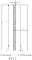
FIG. 2 is a schematic diagram of a work overlap value according to an embodiment of this specification; -
Fig. 3 is a schematic diagram of a case in which a work overlap value according to an embodiment of this specification changes with a slope; -
FIG. 4 is a structural block diagram of a moving path planning apparatus for an autonomous robot according to some embodiments of this specification; -
FIG. 5 is a schematic diagram of a two-dimensional map of a target working area according to an embodiment of this specification; -
FIG. 6 is a schematic diagram of slope distribution of a target working area according to an embodiment of this specification; -
FIG. 7 is a schematic diagram of zones of a target working area according to an embodiment of this specification; -
FIG. 8 is a schematic diagram of a direction of a moving path in a slope area within a target working area according to an embodiment of this specification; -
FIG. 9 is a schematic diagram of planning of a full-coverage working path for a target working area according to an embodiment of this specification; and -
FIG. 10 is a flowchart of a moving path planning method for an autonomous robot according to some embodiments of this specification. - To enable a person skilled in the art to better understand the technical solutions in this specification, the technical solutions of the embodiments of this specification will be described clearly and thoroughly below with reference to the accompanying drawings of the embodiments of this specification. Apparently, the described embodiments are merely some rather than all of the embodiments of this specification. All other embodiments obtained by a person of ordinary skill in the art based on the embodiments of this specification without creative efforts shall fall within the protection scope of this specification.
- For ease of description, in some embodiments described below, an example in which a full-coverage working path is a square wave-shaped path is used for description. However, it should be understood by those skilled in the art that this specification is not limited thereto. In other embodiments, the full-coverage working path may be a spiral path or a concentric rectangle path.
- Environmental information in this specification refers to terrain distribution environmental information (hereinafter referred to as terrain distribution information). The terrain distribution information may be used for representing an absolute height, a relative height difference, or steepness of a slope of earth surface morphology. For ease of description, in some embodiments described below, an example in which the terrain distribution information is slope distribution information is used for description. However, this specification is not limited thereto. In other embodiments, the terrain distribution information may be an absolute height distribution, a relative height difference distribution, a height change rate distribution, or the like.
- Maps mentioned in this specification are all two-dimensional maps. Specifically, the maps mentioned in this specification may be topographic maps or plane maps.
- A slope area in this specification refers to an area with terrain distribution satisfying set conditions in a target working area. For example, in some embodiments of this specification, slope distribution information is used as an example. An area with a slope angle value reaching a first slope angle value in a target working area may be used as a slope area.
- Referring to
FIG. 1 , anautonomous robot 100 according to some embodiments of this specification may move autonomously within aworking area 200 to automatically perform a work task. In some exemplary embodiments, theautonomous robot 100 may be, for example, an automatic lawn mower, an automatic cleaning device, an automatic watering apparatus, or an automatic snow sweeper. - In a full-coverage working mode, the autonomous robot generally moves along a planned full-coverage moving path to work.
- When the autonomous robot plans the full-coverage working path based on an ox-turning method or another method, the working area is generally flat by default. When the autonomous robot moves in a flat working area, a work overlap value between adjacent path segments is fixed, and a coverage of full-coverage work can be ensured. In an embodiment of this specification, the work overlap value refers to an overlapped portion between a working width of the autonomous robot working along one of the adjacent path segments and a working width of the autonomous robot working along the other of the adjacent path segments. For example, in
FIG. 2 , an nth path segment is adjacent to an (n+1)th path segment, a working width of the autonomous robot working along the nth path segment is w, a working width of the autonomous robot working along the (n+1)th path segment is w, and a work overlap value between the two adjacent path segments is d (for example, as shown by a portion where oblique lines are drawn inFIG. 2 ). - However, in practice, the autonomous robot may sometimes work in a non-flat working area. For example, in a scenario shown in
FIG. 3 , when the autonomous robot works in a flat area, a work overlap value between adjacent path segments (as shown by the vertical dashed lines inFIG. 3 ) is a default value (for example, Δ1 inFIG. 3 ). When the autonomous robot works in an area with aslope 1, a work overlap value between adjacent path segments is Δ2=A-(A-Δ1))/cosα , where A is a working width of the autonomous robot, α is a slope angle of theslope 1, cosα=L1/L2, L1 is a width between adjacent path segments in the flat area, and L2 is a width between adjacent path segments in the area with theslope 1. Because L2 > L1 and the working width of the autonomous robot is fixed, Δ2 < Δ1. When the autonomous robot works onslope 2 with a larger slope angle, a work overlap value between adjacent path segments is Δ3=A-(A-Δ1))/cosβ, β is a slope angle of theslope 2, cosβ=L1/L3 , and L3 is a width between adjacent path segments in an area with theslope 2. Because L3 >L2 > L1 and the working width of the autonomous robot is fixed, Δ3 < Δ2 < Δ1. - Generally, the working width of the autonomous robot is determined by a working execution mechanism of the autonomous robot. For example, in an exemplary embodiment, when the autonomous robot is a robotic lawn mower, the diameter of a cutting deck of the robotic lawn mower is a working width of the robotic lawn mower.
- Therefore, it can be seen that the work overlap value between adjacent path segments decreases with the increase of the slope angle. When the slope angle is greater than a particular value (for example, as shown by β in
FIG. 3 ), the autonomous robot misses a working area, which reduces a work coverage ratio of the autonomous robot in the full-coverage mode. - For example, a working area of an automatic lawn mower is used as an example. An actual lawn usually has uneven terrain such as high slopes due to a special layout of a user's residential environment or garden. If the automatic lawn mower keeps performing coverage cutting based on a full-coverage working path planned based on a two-dimensional map, the autonomous robot is prone to a cutting miss in a high slope scenario.
- In view of this, to solve the problem that an autonomous robot tends to miss a working area in a high slope scenario, the autonomous robot according to some embodiments of this specification is provided with a moving path planning apparatus. The moving path planning apparatus can automatically adjust a work overlap value between adjacent path segments during planning of a moving path in a target working area, to keep the work overlap value between the adjacent path segments within an appropriate range. Therefore, the problem that the autonomous robot misses a working area in a high slope scenario can be effectively prevented, and a work coverage ratio of the autonomous robot in a full-coverage mode is therefore improved.
- In some embodiments of this specification, the automatically adjusting a work overlap value between adjacent path segments may include: automatically adjusting the work overlap value between the adjacent path segments according to environmental information of the autonomous robot.
- For example, referring to
FIG. 4 , in some embodiments of this specification, the moving path planning apparatus may include a terraininformation obtaining module 41, a slopearea determining module 42, and a movingpath planning module 42. The terraininformation obtaining module 41 may be configured to obtain terrain distribution information of a target working area. The slopearea determining module 42 may be configured to determine, according to the terrain distribution information, whether a slope area exists in the target working area. The movingpath planning module 43 may be configured to determine, if a slope area exists in the target working area, a width value between adjacent path segments according to the terrain distribution information during planning of a moving path in the slope area, to keep a work overlap value between the adjacent path segments within a specified range (for example, 1 cm to 5 cm). - Based on the moving path planning apparatus, in the full-coverage working mode, if a slope area exists in the target working area, the autonomous robot may determine a width value between adj acent path segments according to the terrain distribution information during planning of a moving path in the slope area, to keep a work overlap value between adjacent path segments within a range not less than zero, thereby effectively preventing the autonomous robot from missing a working area in the high slope scenario.
- In some embodiments of this specification, assuming that a path segment m and a path segment n are adjacent path segments, a distance from any location point x on the path segment n to the path segment m is a width between the location point x on the path segment n and the path segment m (for example, shown by L1, L2, and L3 in
FIG. 3 ). Therefore, the width L x between the location point x on the path segment n and the path segment m may be calculated by the formula
- In some other embodiments of this specification, on the premise that the work overlap value is not less than zero, the work overlap value should not be excessively large (for example, exceeds the value of a default work overlap value), to avoid affecting the working efficiency of the autonomous robot due to a large work overlap value.
- In some embodiments of this specification, the terrain
information obtaining module 41 may allow the autonomous robot to traverse the target working area in advance and invoke an inclination sensor, a gyroscope, or the like provided in the autonomous robot to acquire slope distribution information of the target working area during traversal. For example, in an exemplary embodiment, the traversal may be implemented only to acquire slope distribution information. In another exemplary embodiment, the traversal may be performing a full-coverage work task and at the same time acquiring slope distribution information in the process of performing the work task. Certainly, before the traversal, the autonomous robot may plan the full-coverage working path according to a two-dimensional map (for example, as shown inFIG. 5 ) created in a mapping stage (it can be understood that, terrain is not taken into consideration in the planning of the full-coverage working path in this case), to facilitate the traverse of the target working area by the autonomous robot according to the full-coverage working path, thereby acquiring slope distribution information of the target working area. - Experiments and studies show that when the slope angle reaches a particular value (hereinafter referred to as a first slope angle value), the work coverage ratio of the autonomous robot in the full-coverage mode may be substantially affected. Therefore, the first slope angle value may be used as a boundary to define the flat area and the slope area. That is, in the target working area, an area with a slope angle less than the first slope angle value may be referred to as the flat area, and an area with a slope angle reaching the first slope angle value may be referred to as the slope area. Generally, the slope distribution information of the target working area may be represented by a uniform slope distribution map of the target working area. Therefore, the slope
area determining module 42 may determine whether a slope area exists in the target working area through a uniform slope line on the uniform slope distribution map. For example, in an exemplary embodiment shown inFIG. 6 , assuming that a slope angle of 10° is used as the first slope angle value, the slope area in the target working area may be determined by deleting or concealing contour lines of flat areas with slope angles less than 10° and keeping areas with slope angles not less than 10°. - If a slope area exists in the target working area, to appropriately plan a moving path in the slope area, the moving
path planning module 43 may first partition the target working area. For example, when the slope area is a regular area (that is, the outer contour of the slope area has a regular shape such as a rectangle), the target working area may be directly partitioned by using the outer contour of the slope area as a boundary, to facilitate subsequent moving path planning. - In some other embodiments of this specification, when the slope area is an irregular area (that is, the outer contour of the slope area has an irregular shape), the moving
path planning module 43 may virtually regularize the slope area to make the slope area form a regular working area with a virtual boundary, thereby further facilitating subsequent moving path planning. For example, in an exemplary embodiment shown inFIG. 7 , there are two slope areas S1 and S2 in the target working area. Because both S1 and S2 are irregular areas, S1 and S2 may be virtually regularized by, for example, generating the smallest circumscribed rectangles of S1 and S2 (for example, shown by the thin dot-dashed line inFIG. 7 ). After virtual regularization, the entire target working area may be divided into seven work zones A, B, C, D, E, S1, and S2 based on the virtual boundaries of S1 and S2 and the boundary of the target working area. - After the entire target working area is divided into a plurality of work zones, the moving
path planning module 43 may separately plan a full-coverage working path for each work zone. Generally, for work zones located in the flat area, during planning of a square wave-shaped path, the movingpath planning module 43 may plan each path segment according to a default path segment interval (that is, a width value between adjacent path segments). For work zones located in the slope area, to avoid missing a working area, the movingpath planning module 43 may adaptively adjust a width value (for example, adjust L2 and L3 inFIG. 3 ) between adjacent path segments according to a slope angle value of each location point on adjacent path segments and the working width of the autonomous robot, to keep the work overlap value between the adjacent path segments within a specified range. The adaptive adjustment means that a width value between adjacent path segments is adjusted according to the largest slope angle value (for example, 0°, 20°, 30°) of a slope area having different slopes, so that even at the largest slope angle, the corresponding work overlap value is positive, that is, there is no possibility of missing a working area. - A square wave-shaped path is used as an example. For work zones located in the flat area, during planning of the square wave-shaped path, the moving
path planning module 43 can plan each path segment according to a default moving direction (for example, a moving direction in the five work zones A, B, C, D, and E inFIG. 9 is the default moving direction). For work zones located in the slope area, in consideration of a climbing limit of the autonomous robot and other factors, during planning of moving directions in the work zones located in the slope area, the movingpath planning module 43 needs to avoid a gradient direction of the slope area as much as possible, making it less difficult for the autonomous robot to climb. - For example, in an embodiment of this specification, if a slope area exists in the target working area, the moving
path planning module 43 may first determine the gradient direction of the slope area (for example, as shown by a solid double-headed arrow inFIG. 8 ); and determine whether a slope angle value corresponding to the gradient direction exceeds a second slope angle value (the second slope angle value may be set based on the climbing limit of the autonomous robot), where the second slope angle value is greater than the first slope angle value. If the slope angle value corresponding to the gradient direction exceeds the second slope angle value, it indicates that the largest slope angle of the slope area may affect the climbing of the autonomous robot. Therefore, during planning of a moving path in the work zones located in the slope area, the movingpath planning module 43 may keep an angle between the moving direction of the moving path and the gradient direction within a specified angle range. - In another embodiment of this specification, if the slope angle value corresponding to the gradient direction exceeds the second slope angle value, during planning of a moving path in the work zones located in the slope area, the moving
path planning module 43 may make the angle between the moving direction of the moving path and the gradient direction be a specified value. When the specified value is larger, it is less difficult for the autonomous robot to climb. Therefore, when the specified value is 90° (for example, as shown by dot-dashed double-headed arrow inFIG. 9 ), the difficulty for the autonomous robot to climb can be reduced to the minimum. - Certainly, in another embodiment of this specification, if the slope angle value corresponding to the gradient direction does not exceed the second slope angle value, it indicates that the largest slope angle of the slope area does not affect the climbing of the autonomous robot. Therefore, during planning of a moving path in the slope area, the moving
path planning module 43 may use the default moving direction as the moving direction of the moving path. - After the moving direction of each path segment in each work zone and the path segment interval is determined, the corresponding square wave-shaped path can be drawn (for example, as shown in
FIG. 9 ), thereby completing the planning of the full-coverage working path for the target working area while taking the slope information of the target working area into consideration. After the planning of the full-coverage working path for the target working area is completed, the autonomous robot can subsequently perform each full-coverage work task according to the full-coverage working path. - For ease of description, when the apparatus is described, the apparatus is divided into units according to functions, which are separately described. Certainly, during implementation of this specification, the functions of the units may be implemented in the same piece of or a plurality of pieces of software and/or hardware.
- Corresponding to the foregoing moving path planning apparatus for an autonomous robot, a moving path planning method for an autonomous robot of this specification may include: automatically adjusting a work overlap value between adj acent path segments during planning of a moving path in a target working area.
- In some embodiments of this specification, the automatically adjusting a work overlap value between adjacent path segments may include: automatically adjusting the work overlap value between the adjacent path segments according to environmental information of the autonomous robot.
- For example, referring to
FIG. 10 , in some embodiments of this specification, the moving path planning method for an autonomous robot may include the following steps: - S101: Obtain terrain distribution information of a target working area.
- S102: Determine, according to the terrain distribution information, whether a slope area exists in the target working area, where a slope angle value of the slope area reaches a first slope angle value.
- S103: Determine, if a slope area exists in the target working area, a width value between adjacent path segments according to the terrain distribution information during planning of a moving path in the slope area, to keep a work overlap value between the adjacent path segments within a specified range.
- In the moving path planning method according to some embodiments of this specification, the terrain distribution information includes at least one of the following: slope distribution information, absolute height distribution information, relative height difference distribution information, or height change rate distribution information.
- In the moving path planning method according to some embodiments of this specification, the determining, according to the terrain distribution information, whether a slope area exists in the target working area includes:
determining, according to whether a slope angle value of the slope area reaches a first slope angle value, whether a slope area exists in the target working area. - In the moving path planning method according to some embodiments of this specification, the determining a width value between adjacent path segments according to the slope distribution information includes:
determining the width value between the adjacent path segments according to a slope angle value of each location point on the adjacent path segments and a working width of the autonomous robot. - In the moving path planning method according to some embodiments of this specification, the method further includes:
- when a slope area exists in the target working area, determining a gradient direction of the slope area;
- determining whether a slope angle value corresponding to the gradient direction exceeds a second slope angle value, where the second slope angle value is greater than the first slope angle value; and
- if the slope angle value corresponding to the gradient direction exceeds the second slope angle value, keeping an angle between a moving direction of the moving path and the gradient direction within a specified angle range during planning of the moving path in the slope area.
- In the moving path planning method according to some embodiments of this specification, the keeping an angle between a moving direction of the moving path and the gradient direction within a preset angle range includes:
making the angle between the moving direction of the moving path and the gradient direction be a specified value. - In the moving path planning method according to some embodiments of this specification, the method further includes:
if the slope angle value corresponding to the gradient direction does not exceed the second slope angle value, using a default moving direction as the moving direction of the moving path during planning of the moving path in the slope area. - In the moving path planning method according to some embodiments of this specification, the obtaining terrain distribution information of a target working area includes:
acquiring the terrain distribution information of the target working area in a process of making the autonomous robot traverse the target working area. - In the moving path planning method according to some embodiments of this specification, the terrain distribution information of a target working area includes:
a uniform slope distribution map of the target working area. - Although the processes described above include a plurality of operations that appear in a particular sequence, it should be clearly understood that these processes may include more or fewer operations which can be performed in sequence or in a parallel manner (for example, by using a parallel processor or in a multithread environment).
- The present invention is described with reference to the flowcharts and/or block diagrams of the method, the device (system), and the computer program product according to the embodiments of the present invention. It should be understood that computer program instructions can implement each procedure and/or block in the flowcharts and/or block diagrams and a combination of procedures and/or blocks in the flowcharts and/or block diagrams. These computer program instructions may be provided to a general-purpose computer, a special-purpose computer, an embedded processor, or a processor of another programmable data processing device to generate a machine, so that an apparatus configured to implement functions specified in one or more procedures in the flowcharts and/or one or more blocks in the block diagrams is generated by using instructions executed by the computer or the processor of another programmable data processing device.
- These computer program instructions may be stored in a computer-readable memory that can instruct a computer or another programmable data processing device to work in a specific manner, so that the instructions stored in the computer-readable memory generate an artifact that includes an instruction apparatus. The instruction apparatus implements a specific function in one or more procedures in the flowcharts and/or in one or more blocks in the block diagrams.
- These computer program instructions may be loaded onto a computer or another programmable data processing device, so that a series of operations and steps are performed on the computer or the another programmable device, thereby generating computer-implemented processing. Therefore, the instructions executed on the computer or the another programmable device provide steps for implementing a specific function in one or more processes in the flowcharts and/or in one or more blocks in the block diagrams.
- In a typical configuration, a computing device includes one or more processors (CPUs), an input/output (I/O) interface, a network interface, and an internal memory.
- The memory may include a form such as a volatile memory, a random access memory (RAM), and/or a non-volatile memory such as a read-only memory (ROM) or a flash memory (flash RAM) in a computer-readable medium. The memory is an example of the computer-readable medium.
- The computer-readable medium includes a non-volatile medium and a volatile medium, a removable medium and a non-removable medium, which may implement storage of information by using any method or technology. The information may be a computer-readable instruction, a data structure, a program module, or other data. Examples of a storage medium of a computer include, but are not limited to, a phase change memory (PRAM), a static random access memory (SRAM), a dynamic random access memory (DRAM), or other types of RAMs, a ROM, an erasable programmable read only memory (EEPROM), a flash memory or another storage technology, a compact disc read-only memory (CD-ROM), a digital versatile disc (DVD) or another optical storage, or a cartridge tape. A magnetic storage of a magnetic disk or a disc, another magnetic storage device, or any other non-transmission medium may be configured to store information that can be accessed by a computing device. Based on the description in the present disclosure, the computer-readable medium does not include transitory computer-readable media (transitory media), such as a modulated data signal and a carrier.
- It should be further noted that the terms "include", "comprise", or any variants thereof are intended to cover a non-exclusive inclusion. Therefore, a process, method, or device that includes a series of elements not only includes such elements, but also includes other elements not specified expressly, or may include inherent elements of the process, method, or device. Without further limitation, the element defined by a phrase "include one" does not exclude other same elements in the process, method, or device which include the element.
- A person skilled in the art should understand that the embodiments of this specification may be provided as a method, a system, or a computer program product. Therefore, this specification may use a form of hardware only embodiments, software only embodiments, or embodiments with a combination of software and hardware. Moreover, this specification may use a form of a computer program product that is implemented on one or more computer-usable storage media (including but not limited to a disk memory, a CD-ROM, an optical memory, and the like) that include computer-usable program code.
- This specification can be described in the general context of computer-executable instructions executed by a computer, for example, program modules. Generally, the program module includes a routine, a program, an object, a component, a data structure, and the like for executing a particular task or implementing a particular abstract data type. This specification may be implemented in a distributed computing environment in which tasks are performed by remote processing devices connected by using a communication network. In a distributed computing environment, the program module may be located in both local and remote computer storage media including storage devices.
- The embodiments of this specification are all described in a progressive manner, for same or similar parts in the embodiments, refer to these embodiments, and descriptions of each embodiment focus on a difference from other embodiments. Especially, a method embodiment is basically similar to an apparatus embodiment, and therefore is described briefly; for related parts, reference may be made to partial descriptions in the apparatus embodiment.
- The descriptions are merely embodiments of this specification, and are not intended to limit this specification. For a person skilled in the art, various modifications and changes may be made to this specification. Any modification, equivalent replacement, and improvement made within the spirit and principle of this specification shall fall within the scope of the claims of this specification.
Claims (13)
- A moving path planning method for an autonomous robot, comprising:obtaining terrain distribution information of a target working area, wherein the terrain distribution information comprises at least one of the following: slope distribution information, absolute height distribution information, uniform slope distribution map, relative height difference distribution information, or height change rate distribution information;determining, according to whether a slope angle value of the target working area reaches a first slope angle value, whether a slope area exists in the target working area;determining, if a slope area exists in the target working area, a width value between adjacent path segments according to a slope angle value of each location point on the adjacent path segments and a working width of the autonomous robot during planning of a moving path in the slope area, to keep a work overlap value between the adjacent path segments within a specified range;when a slope area exists in the target working area, determining a gradient direction of the slope area;determining whether a slope angle value corresponding to the gradient direction exceeds a second slope angle value, wherein the second slope angle value is greater than the first slope angle value; andif the slope angle value corresponding to the gradient direction exceeds the second slope angle value, keeping an angle between a moving direction of the moving path and the gradient direction within a specified angle range during planning of the moving path in the slope area.
- A moving path planning method for an autonomous robot, wherein comprising:obtaining terrain distribution information of a target working area;determining, according to the terrain distribution information, whether a slope area exists in the target working area; anddetermining, if a slope area exists in the target working area, a width value between adjacent path segments according to the terrain distribution information during planning of a moving path in the slope area, to keep a work overlap value between the adjacent path segments within a specified range.
- The moving path planning method for an autonomous robot according to claim 2, wherein the terrain distribution information comprises at least one of the following: slope distribution information, absolute height distribution information, relative height difference distribution information, or height change rate distribution information.
- The moving path planning method for an autonomous robot according to claim 2, wherein the determining, according to the terrain distribution information, whether a slope area exists in the target working area comprises:
determining, according to whether a slope angle value of the target working area reaches a first slope angle value, whether a slope area exists in the target working area. - The moving path planning method for an autonomous robot according to claim 4, wherein the determining a width value between adjacent path segments according to the slope distribution information comprises:
determining the width value between the adjacent path segments according to a slope angle value of each location point on the adjacent path segments and a working width of the autonomous robot. - The moving path planning method for an autonomous robot according to claim 4, wherein the method further comprises:when a slope area exists in the target working area, determining a gradient direction of the slope area;determining whether a slope angle value corresponding to the gradient direction exceeds a second slope angle value, wherein the second slope angle value is greater than the first slope angle value; andif the slope angle value corresponding to the gradient direction exceeds the second slope angle value, keeping an angle between a moving direction of the moving path and the gradient direction within a specified angle range during planning of the moving path in the slope area.
- The moving path planning method for an autonomous robot according to claim 6, wherein the keeping an angle between a moving direction of the moving path and the gradient direction within a preset angle range comprises:
making the angle between the moving direction of the moving path and the gradient direction be a specified value. - The moving path planning method for an autonomous robot according to claim 6, wherein the method further comprises:
if the slope angle value corresponding to the gradient direction does not exceed the second slope angle value, using a default moving direction as the moving direction of the moving path during planning of the moving path in the slope area. - The moving path planning method for an autonomous robot according to claim 2, wherein the obtaining terrain distribution information of a target working area comprises:
acquiring the terrain distribution information of the target working area in a process of making the autonomous robot traverse the target working area. - The moving path planning method for an autonomous robot according to claim 2, wherein the terrain distribution information of the target working area comprises:
a uniform slope distribution map of the target working area. - A moving path planning apparatus for an autonomous robot, wherein comprising:a terrain information obtaining module, configured to obtain terrain distribution information of a target working area;a slope area determining module, configured to determine, according to the terrain distribution information, whether a slope area exists in the target working area; anda moving path planning module, configured to determine, if a slope area exists in the target working area, a width value between adjacent path segments according to the terrain distribution information during planning of a moving path in the slope area, to keep a work overlap value between the adjacent path segments within a specified range.
- An autonomous robot, wherein configured with the moving path planning apparatus according to claim 11.
- A computer storage medium, wherein storing a computer program, the computer program, when executed by a processor, implementing the moving path planning method according to any one of claims 2 to 10.
Applications Claiming Priority (2)
| Application Number | Priority Date | Filing Date | Title |
|---|---|---|---|
| CN201910924785.4A CN112578777A (en) | 2019-09-27 | 2019-09-27 | Autonomous robot and walking path planning method and device thereof and storage medium |
| PCT/CN2020/117800 WO2021057909A1 (en) | 2019-09-27 | 2020-09-25 | Autonomous robot, travel path planning method and apparatus thereof, and storage medium |
Publications (3)
| Publication Number | Publication Date |
|---|---|
| EP4036679A1 true EP4036679A1 (en) | 2022-08-03 |
| EP4036679A4 EP4036679A4 (en) | 2023-08-30 |
| EP4036679B1 EP4036679B1 (en) | 2024-09-04 |
Family
ID=75109873
Family Applications (1)
| Application Number | Title | Priority Date | Filing Date |
|---|---|---|---|
| EP20867377.2A Active EP4036679B1 (en) | 2019-09-27 | 2020-09-25 | Autonomous robot, travel path planning method and apparatus thereof, and storage medium |
Country Status (4)
| Country | Link |
|---|---|
| US (1) | US12235649B2 (en) |
| EP (1) | EP4036679B1 (en) |
| CN (1) | CN112578777A (en) |
| WO (2) | WO2021056789A1 (en) |
Families Citing this family (12)
| Publication number | Priority date | Publication date | Assignee | Title |
|---|---|---|---|---|
| SE547658C2 (en) * | 2020-12-11 | 2025-11-04 | Husqvarna Ab | Robotic lawnmower system and method for provision of map and selection of robotic work tools in a robotic lawnmower system |
| CN113221856B (en) * | 2021-06-11 | 2022-12-27 | 石家庄铁道大学 | Crowd crowding risk degree detection method, device and equipment |
| CN115718482A (en) * | 2021-08-24 | 2023-02-28 | 科沃斯机器人股份有限公司 | Path planning method, robot and storage medium |
| CN113534823B (en) * | 2021-09-16 | 2021-12-14 | 季华实验室 | Planting robot path planning method, device, electronic device and storage medium |
| CN114442616A (en) * | 2022-01-05 | 2022-05-06 | 中联重科土方机械有限公司 | Control method and device for excavator, processor and excavator |
| CN115032995B (en) | 2022-06-17 | 2023-07-14 | 未岚大陆(北京)科技有限公司 | Motion control method, device, electronic device and computer storage medium |
| CN115291605A (en) * | 2022-07-22 | 2022-11-04 | 松灵机器人(深圳)有限公司 | Path planning method and device, mowing robot and storage medium |
| CN115033110B (en) * | 2022-08-09 | 2022-10-25 | 环球数科集团有限公司 | Virtual human gait simulation and three-dimensional scene path planning system |
| CN115729237B (en) * | 2022-11-04 | 2026-04-21 | 深圳市正浩创新科技股份有限公司 | Path planning methods, path planning devices, self-moving devices, and storage media |
| CN116465407A (en) * | 2023-03-21 | 2023-07-21 | 深圳市正浩创新科技股份有限公司 | Path planning method, device, self-moving device and storage medium |
| CN119803443B (en) * | 2025-01-15 | 2026-02-17 | 深圳库犸科技有限公司 | Map creation method, system, medium, device and program product |
| CN119688292B (en) * | 2025-02-24 | 2025-04-22 | 国网山西省电力公司超高压输电分公司 | A detection device for online monitoring of loose bolts on transmission towers |
Family Cites Families (36)
| Publication number | Priority date | Publication date | Assignee | Title |
|---|---|---|---|---|
| US6837033B2 (en) * | 2002-05-23 | 2005-01-04 | Deere & Company | Agricultural bi-mower with cantilever beam suspension |
| US6907336B2 (en) * | 2003-03-31 | 2005-06-14 | Deere & Company | Method and system for efficiently traversing an area with a work vehicle |
| CA2590382C (en) * | 2007-05-28 | 2012-11-13 | Stanley J. Boyko | Castering wheel assembly for rotary mowers |
| CN201178584Y (en) * | 2008-04-10 | 2009-01-14 | 河南农业大学 | Single Haul Slope Dedicated Lawn Mowers |
| DE102011082416A1 (en) * | 2011-09-09 | 2013-03-14 | Robert Bosch Gmbh | Autonomous working device |
| US10149430B2 (en) | 2013-02-20 | 2018-12-11 | Husqvarna Ab | Robotic work tool configured for improved turning in a slope, a robotic work tool system, and a method for use in the robot work tool |
| CN103125202B (en) * | 2013-03-15 | 2016-03-30 | 中国农业大学 | A kind of Cutting times of rotary mower and device |
| JP5336672B1 (en) * | 2013-04-24 | 2013-11-06 | 有限会社渥美不動産アンドコーポレーション | Self-propelled mower |
| EP3104245A4 (en) * | 2014-02-06 | 2017-11-01 | Yanmar Co., Ltd. | Method for setting travel path of autonomous travel work vehicle |
| DE102014113965A1 (en) * | 2014-09-26 | 2016-03-31 | Claas Selbstfahrende Erntemaschinen Gmbh | Combine with driver assistance system |
| JP6571567B2 (en) * | 2016-03-18 | 2019-09-04 | ヤンマー株式会社 | Route generation system for work vehicles |
| KR20200045004A (en) | 2016-03-30 | 2020-04-29 | 얀마 가부시키가이샤 | Path generation device and work vehicle |
| CN107402570A (en) * | 2016-05-19 | 2017-11-28 | 科沃斯机器人股份有限公司 | Self-movement robot, its control method and combinations thereof robot |
| CN107399377B (en) * | 2016-05-19 | 2021-02-09 | 苏州宝时得电动工具有限公司 | Self-moving equipment and control method thereof |
| CN107643750B (en) * | 2016-07-21 | 2020-05-22 | 苏州宝时得电动工具有限公司 | Method for identifying slope of intelligent walking equipment and intelligent walking equipment |
| CN106239507A (en) * | 2016-08-16 | 2016-12-21 | 成都市和平科技有限责任公司 | A kind of pathfinding robot system and method automatically |
| CN106760261B (en) * | 2016-11-25 | 2022-11-11 | 美建建筑系统(中国)有限公司 | Roof snow sweeping robot |
| KR102700830B1 (en) * | 2016-12-26 | 2024-09-02 | 삼성전자주식회사 | Method and electronic device for controlling unmanned aerial vehicle |
| CN108958066A (en) | 2017-05-19 | 2018-12-07 | 百度在线网络技术(北京)有限公司 | Emulation test method and device |
| CN109425352A (en) * | 2017-08-25 | 2019-03-05 | 科沃斯机器人股份有限公司 | Self-movement robot paths planning method |
| CN107509443B (en) * | 2017-09-05 | 2020-01-17 | 惠州市蓝微电子有限公司 | Slope driving control method and system of intelligent mower |
| WO2019084767A1 (en) * | 2017-10-31 | 2019-05-09 | 深圳市大疆创新科技有限公司 | Movable device working control method and apparatus, and path planning method and apparatus |
| CN110168465B (en) * | 2017-11-16 | 2022-07-15 | 南京泉峰科技有限公司 | Smart mowing system |
| CN108113583B (en) * | 2017-12-30 | 2020-07-14 | 珠海市一微半导体有限公司 | Cleaning method and system for cleaning robot |
| CN110093955A (en) * | 2018-01-30 | 2019-08-06 | 岭东核电有限公司 | Cleaning collection system and its control method for tunnel |
| KR102106100B1 (en) | 2018-02-02 | 2020-05-06 | 엘지전자 주식회사 | Moving robot |
| CN108732590A (en) * | 2018-05-16 | 2018-11-02 | 重庆邮电大学 | A kind of biped robot and a kind of ramp angles measurement method |
| CN108981726A (en) * | 2018-06-09 | 2018-12-11 | 安徽宇锋智能科技有限公司 | Unmanned vehicle semanteme Map building and building application method based on perceptual positioning monitoring |
| CN112352270B (en) * | 2018-06-29 | 2023-03-28 | 日产自动车株式会社 | Driving assistance method and driving assistance device |
| CN109006783A (en) * | 2018-08-01 | 2018-12-18 | 牛贞伟 | A kind of WEEDING DEVICE, farmland intelligence uprooting weed robot |
| CN109041755A (en) * | 2018-09-27 | 2018-12-21 | 山东拜罗智能科技有限公司 | A kind of abrupt slope intelligent grass-removing robot and control method |
| CN208953962U (en) * | 2018-12-05 | 2019-06-07 | 苏州博众机器人有限公司 | A kind of robot tracking control and robot |
| CN109634285B (en) * | 2019-01-14 | 2022-03-11 | 傲基科技股份有限公司 | Mowing robot and control method thereof |
| CN109834711B (en) * | 2019-02-21 | 2021-01-12 | 山东职业学院 | A quadruped robot motion control method, system and robot |
| CN109729814A (en) * | 2019-02-26 | 2019-05-10 | 北斗万春(重庆)智能机器人研究院有限公司 | Self-adaptive regulating and intelligent grass-removing above and below cutterhead |
| CN110132215B (en) * | 2019-04-29 | 2021-08-10 | 丰疆智能科技研究院(常州)有限公司 | Method for automatically acquiring operating width of agricultural machine and method for acquiring operating area of agricultural machine |
-
2019
- 2019-09-27 CN CN201910924785.4A patent/CN112578777A/en active Pending
- 2019-11-22 WO PCT/CN2019/120181 patent/WO2021056789A1/en not_active Ceased
-
2020
- 2020-09-25 EP EP20867377.2A patent/EP4036679B1/en active Active
- 2020-09-25 WO PCT/CN2020/117800 patent/WO2021057909A1/en not_active Ceased
- 2020-09-25 US US17/764,138 patent/US12235649B2/en active Active
Also Published As
| Publication number | Publication date |
|---|---|
| EP4036679B1 (en) | 2024-09-04 |
| EP4036679A4 (en) | 2023-08-30 |
| US20220390953A1 (en) | 2022-12-08 |
| CN112578777A (en) | 2021-03-30 |
| WO2021056789A1 (en) | 2021-04-01 |
| US12235649B2 (en) | 2025-02-25 |
| WO2021057909A1 (en) | 2021-04-01 |
Similar Documents
| Publication | Publication Date | Title |
|---|---|---|
| EP4036679B1 (en) | Autonomous robot, travel path planning method and apparatus thereof, and storage medium | |
| US20230320265A1 (en) | System and method for operating an autonomous robotic working machine within a travelling containment zone | |
| CN112230644B (en) | Autonomous robot, and edge control method, device and storage medium thereof | |
| US11118917B2 (en) | Land mapping and guidance system | |
| US11044842B2 (en) | Path planning for area coverage | |
| CN112306049B (en) | Autonomous robot, obstacle avoidance method and device thereof, and storage medium | |
| US10197407B2 (en) | Method and robot system for autonomous control of a vehicle | |
| US7689356B2 (en) | Method and apparatus for creating curved swath patterns for farm machinery | |
| EP3753387B1 (en) | Robotic vehicle for movable operation in a work area | |
| US12332650B2 (en) | Traversal method and system, robot, and readable storage medium | |
| CN109634276A (en) | Agricultural vehicle unmanned control method, system and agricultural vehicle | |
| CN113352325B (en) | Automatic cleaning method and equipment for culture cabin | |
| CN114600622A (en) | Traveling path planning method, control device, mower and self-moving system | |
| CN113934225A (en) | Plant protection unmanned aerial vehicle route planning method based on full coverage path | |
| CN115235483A (en) | Method for constructing grid map, path planning method, processor and device | |
| WO2022116935A1 (en) | Path range determination method and apparatus, and path planning method and apparatus | |
| CN118329043A (en) | Agricultural machinery full coverage path planning and edge closing method, system, agricultural machinery, equipment and medium | |
| CN111190209A (en) | Parallel cutting method and device for mower and mower | |
| CN120826656A (en) | Control method of autonomous working robot, autonomous working robot and storage medium | |
| CN118672262A (en) | Large-area moving method of self-moving equipment, self-moving equipment and storage medium | |
| EP3696640A1 (en) | Robotic vehicle for movable operation in a work area | |
| CN115979295A (en) | Forklift path planning method, system, equipment and medium based on geometric A star | |
| CN120779975B (en) | Agricultural machinery path planning method for full-flow dynamic obstacle avoidance | |
| CN115993612B (en) | Methods and devices for monitoring the working status of agricultural machinery | |
| US20260050267A1 (en) | Path planning method, autonomous mobile device, and storage medium |
Legal Events
| Date | Code | Title | Description |
|---|---|---|---|
| STAA | Information on the status of an ep patent application or granted ep patent |
Free format text: STATUS: THE INTERNATIONAL PUBLICATION HAS BEEN MADE |
|
| PUAI | Public reference made under article 153(3) epc to a published international application that has entered the european phase |
Free format text: ORIGINAL CODE: 0009012 |
|
| STAA | Information on the status of an ep patent application or granted ep patent |
Free format text: STATUS: REQUEST FOR EXAMINATION WAS MADE |
|
| 17P | Request for examination filed |
Effective date: 20220331 |
|
| AK | Designated contracting states |
Kind code of ref document: A1 Designated state(s): AL AT BE BG CH CY CZ DE DK EE ES FI FR GB GR HR HU IE IS IT LI LT LU LV MC MK MT NL NO PL PT RO RS SE SI SK SM TR |
|
| DAV | Request for validation of the european patent (deleted) | ||
| DAX | Request for extension of the european patent (deleted) | ||
| A4 | Supplementary search report drawn up and despatched |
Effective date: 20230801 |
|
| RIC1 | Information provided on ipc code assigned before grant |
Ipc: B25J 9/16 20060101ALI20230726BHEP Ipc: G05D 1/02 20200101AFI20230726BHEP |
|
| REG | Reference to a national code |
Ref country code: DE Free format text: PREVIOUS MAIN CLASS: G05D0001020000 Ref country code: DE Ref legal event code: R079 Ref document number: 602020037299 Country of ref document: DE Free format text: PREVIOUS MAIN CLASS: G05D0001020000 Ipc: G05D0001000000 |
|
| P01 | Opt-out of the competence of the unified patent court (upc) registered |
Effective date: 20240312 |
|
| GRAP | Despatch of communication of intention to grant a patent |
Free format text: ORIGINAL CODE: EPIDOSNIGR1 |
|
| STAA | Information on the status of an ep patent application or granted ep patent |
Free format text: STATUS: GRANT OF PATENT IS INTENDED |
|
| RIC1 | Information provided on ipc code assigned before grant |
Ipc: G05D 1/00 20060101AFI20240322BHEP |
|
| INTG | Intention to grant announced |
Effective date: 20240426 |
|
| GRAS | Grant fee paid |
Free format text: ORIGINAL CODE: EPIDOSNIGR3 |
|
| GRAA | (expected) grant |
Free format text: ORIGINAL CODE: 0009210 |
|
| STAA | Information on the status of an ep patent application or granted ep patent |
Free format text: STATUS: THE PATENT HAS BEEN GRANTED |
|
| AK | Designated contracting states |
Kind code of ref document: B1 Designated state(s): AL AT BE BG CH CY CZ DE DK EE ES FI FR GB GR HR HU IE IS IT LI LT LU LV MC MK MT NL NO PL PT RO RS SE SI SK SM TR |
|
| REG | Reference to a national code |
Ref country code: GB Ref legal event code: FG4D |
|
| REG | Reference to a national code |
Ref country code: CH Ref legal event code: EP |
|
| REG | Reference to a national code |
Ref country code: IE Ref legal event code: FG4D |
|
| REG | Reference to a national code |
Ref country code: DE Ref legal event code: R096 Ref document number: 602020037299 Country of ref document: DE |
|
| REG | Reference to a national code |
Ref country code: SE Ref legal event code: TRGR |
|
| REG | Reference to a national code |
Ref country code: LT Ref legal event code: MG9D |
|
| REG | Reference to a national code |
Ref country code: NL Ref legal event code: MP Effective date: 20240904 |
|
| PG25 | Lapsed in a contracting state [announced via postgrant information from national office to epo] |
Ref country code: NO Free format text: LAPSE BECAUSE OF FAILURE TO SUBMIT A TRANSLATION OF THE DESCRIPTION OR TO PAY THE FEE WITHIN THE PRESCRIBED TIME-LIMIT Effective date: 20241204 |
|
| PG25 | Lapsed in a contracting state [announced via postgrant information from national office to epo] |
Ref country code: GR Free format text: LAPSE BECAUSE OF FAILURE TO SUBMIT A TRANSLATION OF THE DESCRIPTION OR TO PAY THE FEE WITHIN THE PRESCRIBED TIME-LIMIT Effective date: 20241205 Ref country code: PL Free format text: LAPSE BECAUSE OF FAILURE TO SUBMIT A TRANSLATION OF THE DESCRIPTION OR TO PAY THE FEE WITHIN THE PRESCRIBED TIME-LIMIT Effective date: 20240904 Ref country code: FI Free format text: LAPSE BECAUSE OF FAILURE TO SUBMIT A TRANSLATION OF THE DESCRIPTION OR TO PAY THE FEE WITHIN THE PRESCRIBED TIME-LIMIT Effective date: 20240904 |
|
| PG25 | Lapsed in a contracting state [announced via postgrant information from national office to epo] |
Ref country code: BG Free format text: LAPSE BECAUSE OF FAILURE TO SUBMIT A TRANSLATION OF THE DESCRIPTION OR TO PAY THE FEE WITHIN THE PRESCRIBED TIME-LIMIT Effective date: 20240904 |
|
| PG25 | Lapsed in a contracting state [announced via postgrant information from national office to epo] |
Ref country code: LV Free format text: LAPSE BECAUSE OF FAILURE TO SUBMIT A TRANSLATION OF THE DESCRIPTION OR TO PAY THE FEE WITHIN THE PRESCRIBED TIME-LIMIT Effective date: 20240904 |
|
| PG25 | Lapsed in a contracting state [announced via postgrant information from national office to epo] |
Ref country code: HR Free format text: LAPSE BECAUSE OF FAILURE TO SUBMIT A TRANSLATION OF THE DESCRIPTION OR TO PAY THE FEE WITHIN THE PRESCRIBED TIME-LIMIT Effective date: 20240904 |
|
| PG25 | Lapsed in a contracting state [announced via postgrant information from national office to epo] |
Ref country code: ES Free format text: LAPSE BECAUSE OF FAILURE TO SUBMIT A TRANSLATION OF THE DESCRIPTION OR TO PAY THE FEE WITHIN THE PRESCRIBED TIME-LIMIT Effective date: 20240904 Ref country code: RS Free format text: LAPSE BECAUSE OF FAILURE TO SUBMIT A TRANSLATION OF THE DESCRIPTION OR TO PAY THE FEE WITHIN THE PRESCRIBED TIME-LIMIT Effective date: 20241204 |
|
| PG25 | Lapsed in a contracting state [announced via postgrant information from national office to epo] |
Ref country code: RS Free format text: LAPSE BECAUSE OF FAILURE TO SUBMIT A TRANSLATION OF THE DESCRIPTION OR TO PAY THE FEE WITHIN THE PRESCRIBED TIME-LIMIT Effective date: 20241204 Ref country code: PL Free format text: LAPSE BECAUSE OF FAILURE TO SUBMIT A TRANSLATION OF THE DESCRIPTION OR TO PAY THE FEE WITHIN THE PRESCRIBED TIME-LIMIT Effective date: 20240904 Ref country code: NO Free format text: LAPSE BECAUSE OF FAILURE TO SUBMIT A TRANSLATION OF THE DESCRIPTION OR TO PAY THE FEE WITHIN THE PRESCRIBED TIME-LIMIT Effective date: 20241204 Ref country code: LV Free format text: LAPSE BECAUSE OF FAILURE TO SUBMIT A TRANSLATION OF THE DESCRIPTION OR TO PAY THE FEE WITHIN THE PRESCRIBED TIME-LIMIT Effective date: 20240904 Ref country code: HR Free format text: LAPSE BECAUSE OF FAILURE TO SUBMIT A TRANSLATION OF THE DESCRIPTION OR TO PAY THE FEE WITHIN THE PRESCRIBED TIME-LIMIT Effective date: 20240904 Ref country code: GR Free format text: LAPSE BECAUSE OF FAILURE TO SUBMIT A TRANSLATION OF THE DESCRIPTION OR TO PAY THE FEE WITHIN THE PRESCRIBED TIME-LIMIT Effective date: 20241205 Ref country code: FI Free format text: LAPSE BECAUSE OF FAILURE TO SUBMIT A TRANSLATION OF THE DESCRIPTION OR TO PAY THE FEE WITHIN THE PRESCRIBED TIME-LIMIT Effective date: 20240904 Ref country code: ES Free format text: LAPSE BECAUSE OF FAILURE TO SUBMIT A TRANSLATION OF THE DESCRIPTION OR TO PAY THE FEE WITHIN THE PRESCRIBED TIME-LIMIT Effective date: 20240904 Ref country code: BG Free format text: LAPSE BECAUSE OF FAILURE TO SUBMIT A TRANSLATION OF THE DESCRIPTION OR TO PAY THE FEE WITHIN THE PRESCRIBED TIME-LIMIT Effective date: 20240904 |
|
| REG | Reference to a national code |
Ref country code: AT Ref legal event code: MK05 Ref document number: 1721037 Country of ref document: AT Kind code of ref document: T Effective date: 20240904 |
|
| PG25 | Lapsed in a contracting state [announced via postgrant information from national office to epo] |
Ref country code: NL Free format text: LAPSE BECAUSE OF FAILURE TO SUBMIT A TRANSLATION OF THE DESCRIPTION OR TO PAY THE FEE WITHIN THE PRESCRIBED TIME-LIMIT Effective date: 20240904 |
|
| PG25 | Lapsed in a contracting state [announced via postgrant information from national office to epo] |
Ref country code: PT Free format text: LAPSE BECAUSE OF FAILURE TO SUBMIT A TRANSLATION OF THE DESCRIPTION OR TO PAY THE FEE WITHIN THE PRESCRIBED TIME-LIMIT Effective date: 20250106 Ref country code: IS Free format text: LAPSE BECAUSE OF FAILURE TO SUBMIT A TRANSLATION OF THE DESCRIPTION OR TO PAY THE FEE WITHIN THE PRESCRIBED TIME-LIMIT Effective date: 20250104 |
|
| PG25 | Lapsed in a contracting state [announced via postgrant information from national office to epo] |
Ref country code: SM Free format text: LAPSE BECAUSE OF FAILURE TO SUBMIT A TRANSLATION OF THE DESCRIPTION OR TO PAY THE FEE WITHIN THE PRESCRIBED TIME-LIMIT Effective date: 20240904 Ref country code: RO Free format text: LAPSE BECAUSE OF FAILURE TO SUBMIT A TRANSLATION OF THE DESCRIPTION OR TO PAY THE FEE WITHIN THE PRESCRIBED TIME-LIMIT Effective date: 20240904 |
|
| PG25 | Lapsed in a contracting state [announced via postgrant information from national office to epo] |
Ref country code: EE Free format text: LAPSE BECAUSE OF FAILURE TO SUBMIT A TRANSLATION OF THE DESCRIPTION OR TO PAY THE FEE WITHIN THE PRESCRIBED TIME-LIMIT Effective date: 20240904 Ref country code: AT Free format text: LAPSE BECAUSE OF FAILURE TO SUBMIT A TRANSLATION OF THE DESCRIPTION OR TO PAY THE FEE WITHIN THE PRESCRIBED TIME-LIMIT Effective date: 20240904 |
|
| PG25 | Lapsed in a contracting state [announced via postgrant information from national office to epo] |
Ref country code: CZ Free format text: LAPSE BECAUSE OF FAILURE TO SUBMIT A TRANSLATION OF THE DESCRIPTION OR TO PAY THE FEE WITHIN THE PRESCRIBED TIME-LIMIT Effective date: 20240904 |
|
| PG25 | Lapsed in a contracting state [announced via postgrant information from national office to epo] |
Ref country code: IT Free format text: LAPSE BECAUSE OF FAILURE TO SUBMIT A TRANSLATION OF THE DESCRIPTION OR TO PAY THE FEE WITHIN THE PRESCRIBED TIME-LIMIT Effective date: 20240904 Ref country code: SK Free format text: LAPSE BECAUSE OF FAILURE TO SUBMIT A TRANSLATION OF THE DESCRIPTION OR TO PAY THE FEE WITHIN THE PRESCRIBED TIME-LIMIT Effective date: 20240904 |
|
| REG | Reference to a national code |
Ref country code: CH Ref legal event code: PL |
|
| PG25 | Lapsed in a contracting state [announced via postgrant information from national office to epo] |
Ref country code: LU Free format text: LAPSE BECAUSE OF NON-PAYMENT OF DUE FEES Effective date: 20240925 |
|
| REG | Reference to a national code |
Ref country code: DE Ref legal event code: R097 Ref document number: 602020037299 Country of ref document: DE |
|
| PG25 | Lapsed in a contracting state [announced via postgrant information from national office to epo] |
Ref country code: MC Free format text: LAPSE BECAUSE OF FAILURE TO SUBMIT A TRANSLATION OF THE DESCRIPTION OR TO PAY THE FEE WITHIN THE PRESCRIBED TIME-LIMIT Effective date: 20240904 |
|
| PG25 | Lapsed in a contracting state [announced via postgrant information from national office to epo] |
Ref country code: DK Free format text: LAPSE BECAUSE OF FAILURE TO SUBMIT A TRANSLATION OF THE DESCRIPTION OR TO PAY THE FEE WITHIN THE PRESCRIBED TIME-LIMIT Effective date: 20240904 |
|
| REG | Reference to a national code |
Ref country code: BE Ref legal event code: MM Effective date: 20240930 |
|
| PLBE | No opposition filed within time limit |
Free format text: ORIGINAL CODE: 0009261 |
|
| STAA | Information on the status of an ep patent application or granted ep patent |
Free format text: STATUS: NO OPPOSITION FILED WITHIN TIME LIMIT |
|
| PG25 | Lapsed in a contracting state [announced via postgrant information from national office to epo] |
Ref country code: BE Free format text: LAPSE BECAUSE OF NON-PAYMENT OF DUE FEES Effective date: 20240930 |
|
| PG25 | Lapsed in a contracting state [announced via postgrant information from national office to epo] |
Ref country code: CH Free format text: LAPSE BECAUSE OF NON-PAYMENT OF DUE FEES Effective date: 20240930 |
|
| PG25 | Lapsed in a contracting state [announced via postgrant information from national office to epo] |
Ref country code: IE Free format text: LAPSE BECAUSE OF NON-PAYMENT OF DUE FEES Effective date: 20240925 |
|
| 26N | No opposition filed |
Effective date: 20250605 |
|
| PGFP | Annual fee paid to national office [announced via postgrant information from national office to epo] |
Ref country code: DE Payment date: 20250916 Year of fee payment: 6 |
|
| PGFP | Annual fee paid to national office [announced via postgrant information from national office to epo] |
Ref country code: GB Payment date: 20250919 Year of fee payment: 6 |
|
| PGFP | Annual fee paid to national office [announced via postgrant information from national office to epo] |
Ref country code: FR Payment date: 20250929 Year of fee payment: 6 |
|
| PGFP | Annual fee paid to national office [announced via postgrant information from national office to epo] |
Ref country code: SE Payment date: 20250925 Year of fee payment: 6 |
|
| PG25 | Lapsed in a contracting state [announced via postgrant information from national office to epo] |
Ref country code: CY Free format text: LAPSE BECAUSE OF FAILURE TO SUBMIT A TRANSLATION OF THE DESCRIPTION OR TO PAY THE FEE WITHIN THE PRESCRIBED TIME-LIMIT; INVALID AB INITIO Effective date: 20200925 |
|
| PG25 | Lapsed in a contracting state [announced via postgrant information from national office to epo] |
Ref country code: HU Free format text: LAPSE BECAUSE OF FAILURE TO SUBMIT A TRANSLATION OF THE DESCRIPTION OR TO PAY THE FEE WITHIN THE PRESCRIBED TIME-LIMIT; INVALID AB INITIO Effective date: 20200925 |