EP4036667A1 - Information processing device and information processing method - Google Patents
Information processing device and information processing method Download PDFInfo
- Publication number
- EP4036667A1 EP4036667A1 EP22153413.4A EP22153413A EP4036667A1 EP 4036667 A1 EP4036667 A1 EP 4036667A1 EP 22153413 A EP22153413 A EP 22153413A EP 4036667 A1 EP4036667 A1 EP 4036667A1
- Authority
- EP
- European Patent Office
- Prior art keywords
- information
- sensor
- accessory equipment
- equipment
- information processing
- Prior art date
- Legal status (The legal status is an assumption and is not a legal conclusion. Google has not performed a legal analysis and makes no representation as to the accuracy of the status listed.)
- Pending
Links
Images





Classifications
-
- G—PHYSICS
- G05—CONTROLLING; REGULATING
- G05B—CONTROL OR REGULATING SYSTEMS IN GENERAL; FUNCTIONAL ELEMENTS OF SUCH SYSTEMS; MONITORING OR TESTING ARRANGEMENTS FOR SUCH SYSTEMS OR ELEMENTS
- G05B23/00—Testing or monitoring of control systems or parts thereof
- G05B23/02—Electric testing or monitoring
- G05B23/0205—Electric testing or monitoring by means of a monitoring system capable of detecting and responding to faults
- G05B23/0259—Electric testing or monitoring by means of a monitoring system capable of detecting and responding to faults characterized by the response to fault detection
- G05B23/0267—Fault communication, e.g. human machine interface [HMI]
- G05B23/0272—Presentation of monitored results, e.g. selection of status reports to be displayed; Filtering information to the user
-
- G—PHYSICS
- G06—COMPUTING OR CALCULATING; COUNTING
- G06F—ELECTRIC DIGITAL DATA PROCESSING
- G06F3/00—Input arrangements for transferring data to be processed into a form capable of being handled by the computer; Output arrangements for transferring data from processing unit to output unit, e.g. interface arrangements
- G06F3/01—Input arrangements or combined input and output arrangements for interaction between user and computer
- G06F3/03—Arrangements for converting the position or the displacement of a member into a coded form
-
- G—PHYSICS
- G06—COMPUTING OR CALCULATING; COUNTING
- G06F—ELECTRIC DIGITAL DATA PROCESSING
- G06F15/00—Digital computers in general; Data processing equipment in general
- G06F15/16—Combinations of two or more digital computers each having at least an arithmetic unit, a program unit and a register, e.g. for a simultaneous processing of several programs
- G06F15/161—Computing infrastructure, e.g. computer clusters, blade chassis or hardware partitioning
-
- G—PHYSICS
- G06—COMPUTING OR CALCULATING; COUNTING
- G06F—ELECTRIC DIGITAL DATA PROCESSING
- G06F11/00—Error detection; Error correction; Monitoring
- G06F11/30—Monitoring
- G06F11/32—Monitoring with visual or acoustical indication of the functioning of the machine
- G06F11/324—Display of status information
-
- G—PHYSICS
- G06—COMPUTING OR CALCULATING; COUNTING
- G06F—ELECTRIC DIGITAL DATA PROCESSING
- G06F15/00—Digital computers in general; Data processing equipment in general
- G06F15/16—Combinations of two or more digital computers each having at least an arithmetic unit, a program unit and a register, e.g. for a simultaneous processing of several programs
- G06F15/163—Interprocessor communication
Definitions
- the present invention relates to an information processing device and an information processing method.
- JP 2017-92792 discloses a communication system in which a host computer including a display device is connected with a plurality of processing apparatuses each of which includes a programmable logic controller (PLC).
- the host computer obtains information pertaining to a processing apparatus from the processing apparatus, and causes the display device to display the obtained information.
- PLC programmable logic controller
- a technique is used in which PLC incorporated in equipment is operated based on data obtained from a plurality of sensors and a plurality of pieces of accessory equipment.
- a form of connecting the plurality of sensors and the plurality of pieces of accessory equipment to the equipment a form of connecting a plurality of sensors and a plurality of pieces of accessory equipment to equipment via a relay device is known.
- An object of an aspect of the present invention is to prevent an increase in equipment cost.
- an information processing device including at least one processor, the at least one processor executing: a first relaying process for obtaining sensor data transmitted from each of sensors included in a sensor group and providing the sensor data thus obtained to main equipment; a second relaying process for obtaining accessory equipment data transmitted from each of pieces of accessory equipment included in an accessory equipment group and providing the accessory equipment data thus obtained to the main equipment; and a displaying process for causing a display device to display at least any of the sensor data obtained in the first relaying process, information obtained from the sensor data, the accessory equipment data obtained in the second relaying process, and information obtained from the accessory equipment data.
- an information processing method comprising a first relaying process for obtaining, by at least one processor, sensor data transmitted from each of sensors included in a sensor group and providing, by the at least one processor, the sensor data thus obtained to main equipment; a second relaying process for obtaining, by the at least one processor, accessory equipment data transmitted from each of pieces of accessory equipment included in an accessory equipment group and providing, by the at least one processor, the accessory equipment data thus obtained to the main equipment; and a displaying process for causing, by the at least one processor, a display device to display at least any of the sensor data obtained in the first relaying process, information obtained from the sensor data, the accessory equipment data obtained in the second relaying process, and information obtained from the accessory equipment data.
- the at least one processor may cause the display device to display information indicating a status of a sensor selected from among the sensors included in the sensor group based on a user operation and to display sensor data transmitted from that sensor.
- the at least one processor may cause the display device to display information indicating a status of a piece of accessory equipment selected from among the pieces of accessory equipment included in the accessory equipment group based on a user operation, and to display information pertaining to inspection timing that is obtained from the number of times of operation of that piece of accessory equipment.
- the at least one processor may cause the display device to display, simultaneously in a list form, the sensor data obtained in the first relaying process or the information obtained from the sensor data and the accessory equipment data obtained in the second relaying process or the information obtained from the accessory equipment data.
- the at least one processor further executes a determining process for determining whether or not the sensor data obtained in the first relaying process satisfies a particular condition and the accessory equipment data obtained in the second relaying process satisfies a particular condition; and, in the displaying process, the at least one processor causes the display device to display an error based on a result of the determining process.
- the at least one processor may further execute a changing process for changing each of the particular conditions based on a user operation.
- the embodiments disclosed regarding the information processing device may be applied to the information processing method mutatis mutandis.
- An information processing device in accordance with the present application is a device for relaying communication between sensors included in a sensor group and main equipment, and relaying communication between pieces of accessory equipment included in an accessory equipment group and the main equipment.
- the following description will discuss details of an information processing device in accordance with the present embodiment with reference to the drawings.
- Fig. 1 is a front view illustrating an appearance of the information processing device 1.
- the information processing device 1 includes a power source button 7, a power source pilot lamp 8, and an abnormality pilot lamp 9.
- the power source button 7 is a button for starting or stopping the information processing device 1.
- the power source pilot lamp 8 is a pilot lamp for indicating that the information processing device 1 is in operation. In a state in which the information processing device 1 is in operation, the power source pilot lamp 8 is on. In a state in which the information processing device 1 is stopped, the power source pilot lamp 8 is off.
- the abnormality pilot lamp 9 is a pilot lamp for indicating that an abnormality is occurring in the information processing device 1.
- the abnormality pilot lamp 9 In a state in which the information processing device 1 is in normal operation, the abnormality pilot lamp 9 is off. In a state in which the information processing device 1 is not in normal operation, the abnormality pilot lamp 9 is on.
- the abnormality pilot lamp 9 can be configured to be turned on when an abnormality occurs in the sensor or the accessory equipment that is connected to the information processing device 1.
- Fig. 2 is a block diagram illustrating the configuration of the information processing system S.
- the information processing system S includes main equipment 2, a sensor group 3, an accessory equipment group 4, and a display device 5 in addition to the information processing device 1.
- the main equipment 2 is a device which plays a main role in a production line.
- the main equipment 2 can be, for example, a molding machine for forming a mold.
- the main equipment 2 includes a programmable logic controller (PLC) 21.
- PLC 21 controls components of the main equipment 2 based on sensor data obtained, via the information processing device 1, from sensors constituting the sensor group 3 and based on pieces of equipment data obtained, via the information processing device 1, from pieces of accessory equipment constituting the accessory equipment group 4.
- the sensor group 3 includes a plurality of sensor slave units 3a1, 3a2,... (an example of “sensors” in claims) and a sensor master unit 3b.
- sensor slave units 3a1, 3a2,... an example of “sensors” in claims
- sensor master unit 3b the sensor master unit 3b.
- the sensor slave unit 3a is a device for detecting surrounding statuses of the sensor slave unit 3a, e.g., a status of the main equipment 2, a surrounding status of the main equipment 2, a status of accessory equipment 4a, a surrounding status of the accessory equipment 4a, a status of a raw material, a status of an intermediate product, or a status of a product.
- the sensor slave unit 3a can be, for example, an open/close sensor, a temperature sensor, PAT-LITE (registered trademark), or the like.
- the sensor slave unit 3a transmits, to the sensor master unit 3b, a detection value of the sensor slave unit 3a along with status information of the sensor slave unit 3a as sensor data.
- the status information of the sensor slave unit 3a indicates, for example, a usage status of the sensor slave unit 3a, presence or absence of a monitoring function, a communication status, radio field intensity, or a remaining battery capacity.
- the sensor slave unit 3a is wirelessly connected to the sensor master unit 3b via, for example, EnOcean (registered trademark), ZigBee (registered trademark), Bluetooth Low Energy (registered trademark), or the like.
- a sensor device which has a plurality of sensor functions, e.g., a temperature/humidity sensor which detects both a temperature and humidity.
- each of sensor functions of a sensor device is dealt with as the sensor slave unit 3a. Therefore, a plurality of sensor slave units 3a can correspond to a single sensor device.
- the sensor master unit 3b is a device for relaying communication between each of the sensor slave units 3a and the information processing device 1.
- the sensor master unit 3b transmits, to the information processing device 1, detection values and status information of the sensor slave units 3a that are connected to the sensor master unit 3b along with status information of the sensor master unit 3b as sensor data.
- the status information of the sensor master unit 3b indicates, for example, a communication status and the number of times of data obtainment of the sensor master unit 3b.
- the sensor master unit 3b is connected to the information processing device 1 via wired connection by, for example, Ethernet (registered trademark).
- the accessory equipment group 4 is constituted by a plurality of pieces of accessory equipment 4a1, 4a2, and so forth.
- the accessory equipment 4a is referred to as "accessory equipment 4a".
- the accessory equipment 4a is a device for assisting the main equipment 2.
- the accessory equipment 4a can be, for example, a conveyor, a cylinder, a dust collector, or the like.
- the accessory equipment 4a includes a PLC 41.
- the PLC 41 of each of pieces of accessory equipment 4a controls components of that accessory equipment 4a.
- the PLC 41 of each of the pieces of accessory equipment 4a transmits, to the information processing device 1, digital output and analog output of that accessory equipment 4a along with status information of that accessory equipment 4a as equipment data.
- the digital output of the accessory equipment 4a is also called "operation signal" and indicates, for example, whether or not automatic operation is available, whether or not the equipment is in automatic operation, whether or not an abnormality is occurring, or whether or not the equipment is in emergency stop.
- the analog output of the accessory equipment 4a indicates, for example, a feeding speed of a conveyor, operation pressure of a cylinder, an airflow rate of a dust collector, power consumption, or the like.
- the status information of the accessory equipment 4a indicates, for example, a usage status of the accessory equipment 4a, presence or absence of a monitoring function, or a communication status.
- the accessory equipment 4a is connected to the information processing device 1 via wired connection by, for example, CC-Link (registered trademark).
- the information processing device 1 is a device for relaying communication between the main equipment 2 and the sensor group 3, and communication between the main equipment 2 and the accessory equipment group 4.
- the information processing device 1 includes a processor 11, a memory 12, an input/output IF 13, a communication IF 14, and a PLC 15, as illustrated in Fig. 2 .
- the processor 11, the memory 12, the input/output IF 13, the communication IF 14, and the PLC 15 are connected to each other via buses.
- the information processing device 1 can be realized, for example, by adding the PLC 15 to a small single board computer such as Raspberry Pi (registered trademark).
- a sensor data set D1, an equipment data set D2, a sensor address map M1, and an equipment address map M2 are stored together with an information processing program P.
- the processor 11 refers to the sensor data set D1, the equipment data set D2, the sensor address map M1, and the equipment address map M2, and executes an information processing method (described later) in accordance with the information processing program P.
- Examples of devices that can be used as the processor 11 include a central processing unit (CPU).
- Examples of devices that can be used as the memory 12 include a flash memory.
- the input/output IF 13 is an interface for connecting the display device 5.
- the input/output IF 13 for example, high-definition multimedia interface (HDMI) (registered trademark) is used.
- the communication IF 14 is an interface for communicating with the sensor master unit 3b.
- an Ethernet interface is used as the communication IF 14.
- the PLC 15 is a controller for communicating with (the PLC 21 of) the main equipment 2 and (the PLC 41 of) the accessory equipment 4a.
- the PLC 15 can access the equipment data set D2 and the equipment address map M2 via the busses.
- the PLC 15 is connected to (the PLC 21 of) the main equipment 2 and to (the PLC 41 of) the accessory equipment 4a by CC-Link.
- Fig. 3 is a diagram illustrating the configuration of the sensor data set D1.
- the sensor data set D1 is constituted by configuration information 91, status information 92, output information 93, and monitor information 94.
- Pieces of information constituting the configuration information 91, the status information 92, the output information 93, and the monitor information 94 are managed with consecutive word numbers.
- a leading portion of word number of the configuration information 91 is "Head”
- a leading portion of word number of the status information 92 is "Comm.”
- a leading portion of word number of the output information 93 is "Data”
- a leading portion of word number of the monitor information 94 is "Mon.”
- each of the leading portions indicates content of information corresponding to that word number.
- the configuration information 91 is information indicating a configuration of the sensor group 3.
- the configuration information 91 includes, for example, the number of sensor master units 3b, a type code and an IP address of each sensor master unit 3b, the number of sensor slave units 3a connected to each sensor master unit 3b, the total number of sensor slave units 3a, and a type code of each sensor slave unit 3a.
- the configuration information 91 may be set by a manufacturer prior to shipment of the information processing device 1, or may be set by a user after shipment of the information processing device 1.
- An offset value of a leading word number of each of the status information 92, the output information 93, and the monitor information 94 i.e., a difference from a leading word number of the configuration information 91
- system information of the information processing device 1, and the like may be included in the configuration information 91.
- the status information 92 is a set of status information of each of the sensor slave units 3a and status information of the sensor master unit 3b.
- the status information of each of the sensor slave units 3a is, as described above, obtained from that sensor slave unit 3a via the sensor master unit 3b as sensor data.
- the status information of the sensor master unit 3b is obtained from the sensor master unit 3b as described above.
- the status information 92 may include a keep-alive signal of the information processing system S, sensor slave unit integrated information in which pieces of status information of all the sensor slave units 3a are integrated, and/or the like.
- the sensor slave unit integrated information includes, for example, information indicating whether or not communication statuses of all the sensor slave units 3a are normal, and information indicating whether or not remaining battery capacities of all the sensor slave units 3a are normal.
- the output information 93 is a set of detection values of the sensor slave units 3a.
- the detection value of each of the sensor slave units 3a is obtained as sensor data from that sensor slave unit 3a, as described above.
- the monitor information 94 is a set of a determination condition and a determination result pertaining to each of the sensor slave units 3a.
- the determination condition pertaining to each of the sensor slave units 3a is represented, for example, by a threshold value.
- the determination result pertaining to each of the sensor slave units 3a is given as a result of comparing the detection value of that sensor slave unit 3a with the threshold value.
- the determination condition pertaining to each of the sensor slave units 3a may be set by a manufacturer prior to shipment of the information processing device 1, or may be set by a user after shipment of the information processing device 1.
- the determination result pertaining to each of the sensor slave units 3a is derived from the information processing device 1 each time the detection value of that sensor slave unit 3a is updated.
- Fig. 4 is a diagram illustrating the configuration of the sensor address map M1.
- the sensor address map M1 is a table in which word numbers assigned to respective pieces of information included in the sensor data set D1 are associated with addresses on a memory of the PLC 21 provided in the main equipment 2.
- the processor 11 of the information processing device 1 reads out pieces of information included in the sensor data set D1 as the configuration information 91, the status information 92, the output information 93, and the monitor information 94 from the memory 12 of the information processing device 1, and writes the information to the memory of the PLC 21 provided in the main equipment 2. At this time, the processor 11 of the information processing device 1 determines, in accordance with the sensor address map M1, a region on the memory of the PLC 21 to which each piece of information is to be written. For example, in the sensor address map M1, a word number Data+001 is associated with addresses EEE through E'E'E'.
- the processor 11 of the information processing device 1 writes detection values of a first sensor slave unit, to which the word number Data+001 is assigned in the sensor data set D1, to regions to which the addresses EEE through E'E'E' are assigned in the memory of the PLC 21.
- the processor 11 of the information processing device 1 may write sensor data obtained from the sensors constituting the sensor group 3 to the memory of the PLC 21 provided in the main equipment 2 in accordance with the information processing program P.
- address information equivalent to the foregoing sensor address map M1 is included inside the information processing program P.
- Fig. 5 is a diagram illustrating the configuration of the equipment data set D2.
- the equipment data set D2 is constituted by configuration information 95, status information 96, output information 97, input information 98, and monitor information 99.
- Pieces of information constituting the configuration information 95, the status information 96, the output information 97, the input information 98, and the monitor information 99 are managed with consecutive word numbers.
- a leading portion of word number of the configuration information 95 is "Head”
- a leading portion of word number of the status information 96 is "Comm.”
- a leading portion of word number of the output information 97 is "S_data”
- a leading portion of word number of the input information 98 is “O_data”
- a leading portion of word number of the monitor information 99 is "Mon.”
- each of the leading portions indicates content of information corresponding to that word number.
- the configuration information 95 is information indicating a configuration of the accessory equipment group 4.
- the configuration information 95 includes, for example, the number of pieces of the accessory equipment 4a and a type code of each piece of the accessory equipment 4a.
- An offset value of a leading word number of each of the status information 96, the output information 97, the input information 98, and the monitor information 99 i.e., a difference from a leading word number of the configuration information 95, system information of the information processing device 1, and the like may be included in the configuration information 95.
- the status information 96 is a set of pieces of status information of the pieces of accessory equipment 4a.
- the status information of each piece of the accessory equipment 4a is obtained as the equipment data from that piece of accessory equipment 4a, as described above.
- the status information 96 may include a keep-alive signal of the information processing system S, a low battery signal of the information processing device 1, and/or the like.
- the output information 97 is a set of digital output and analogue output of each piece of the accessory equipment 4a.
- the digital output and analogue output of each piece of the accessory equipment 4a are obtained as the equipment data from that piece of accessory equipment 4a, as described above.
- the output information 97 may include accessory equipment integrated information in which digital outputs (operation signals) of all pieces of the accessory equipment 4a are integrated.
- the accessory equipment integrated information includes, for example, information indicating whether or not all pieces of accessory equipment 4a are normal, and information indicating whether or not all pieces of the accessory equipment 4a can be automatically operated.
- the input information 98 is a set of digital input and analog input of each piece of the accessory equipment 4a.
- the digital input of each piece of the accessory equipment 4a is also called “command signal”, and represents a command to that piece of accessory equipment 4a.
- the analog input of each piece of the accessory equipment 4a is also called “command value”, and represents a command value to that piece of accessory equipment 4a.
- the digital input and analog input of each piece of the accessory equipment 4a are obtained from the PLC 21 of the main equipment 2.
- the input information 98 may include an accessory equipment integrated command in which command signals for all pieces of the accessory equipment 4a are integrated.
- the accessory equipment integrated command includes, for example, an auto-start command for all pieces of accessory equipment that gives an instruction on auto-start to all pieces of the accessory equipment 4a, and an auto-stop command for all pieces of accessory equipment that gives an instruction on auto-stop to all pieces of the accessory equipment 4a.
- the monitor information 99 is a set of a determination condition and a determination result pertaining to each piece of the accessory equipment 4a.
- the determination condition pertaining to each piece of the accessory equipment 4a is represented, for example, by a threshold value.
- the determination result pertaining to each piece of the accessory equipment 4a is given as a result of comparing the digital output of that piece of accessory equipment 4a with the threshold value.
- the determination condition pertaining to each piece of the accessory equipment 4a may be set by a manufacturer prior to shipment of the information processing device 1, or may be set by a user after shipment of the information processing device 1.
- the determination result pertaining to each piece of the accessory equipment 4a is derived by the information processing device 1 each time the digital output of that piece of accessory equipment 4a is updated.
- a determination record pertaining to each piece of the accessory equipment 4a may be included in the monitor information 99.
- the determination record pertaining to each piece of the accessory equipment 4a includes, for example, the number of times the determination result pertaining to that piece of accessory equipment 4a has become true
- Fig. 6 is a diagram illustrating the configuration of the equipment address map M2.
- the equipment address map M2 is a table in which word numbers assigned to respective pieces of information included in the equipment data set D2 are associated with addresses on a memory of the PLC 21 provided in the main equipment 2.
- the processor 11 of the information processing device 1 reads out pieces of information included in the equipment data set D2 as the configuration information 95, the status information 96, the output information 97, and the monitor information 99 from the memory 12 of the information processing device 1, and writes the information to the memory of the PLC 21 provided in the main equipment 2. At this time, the processor 11 of the information processing device 1 determines, in accordance with the equipment address map M2, a region on the memory of the PLC 21 to which each piece of information is to be written. For example, in the equipment address map M2, a word number S_S_Data+001 is associated with addresses UUU through U'U'U'.
- the processor 11 of the information processing device 1 writes digital output of first accessory equipment, to which the word number S_Data+001 is assigned in the equipment data set D2, to regions to which the addresses UUU through U'U'U' are assigned in the memory of the PLC 21.
- the processor 11 of the information processing device 1 reads out pieces of information included in the equipment data set D2 as the input information 98 from the memory of the PLC 21 provided in the main equipment 2, and writes the read information to the memory 12 of the information processing device 1.
- the processor 11 of the information processing device 1 determines, in accordance with the equipment address map M2, a region on the memory of the PLC 21 from which each piece of information is to be read out. For example, in the equipment address map M2, a word number O_Data+001 is associated with addresses WWW through WWW. Therefore, the processor 11 of the information processing device 1 reads out digital input of first accessory equipment, to which the word number O_Data+001 is assigned in the sensor data set D1, from regions to which the addresses WWW through WWW are assigned in the memory of the PLC 21.
- the processor 11 of the information processing device 1 may write pieces of equipment data obtained from the pieces of accessory equipment constituting the accessory equipment group 4 to the memory of the PLC 21 provided in the main equipment 2 in accordance with the information processing program P.
- address information corresponding to the foregoing equipment address map M2 is included inside the information processing program P.
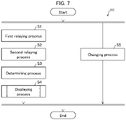
- FIG. 7 is a flowchart showing a display method H1 in which the information processing device 1 causes the display device 5 to display data.
- the display method H1 for displaying data in the information processing device 1 includes a first relaying process S1, a second relaying process S2, and a displaying process S4 as shown in Fig. 7 .
- the first relaying process S1 is a process in which the processor 11 of the information processing device 1 obtains sensor data transmitted from each of the sensor slave units 3a constituting the sensor group 3 and the processor 11 provides the sensor data thus obtained to the main equipment 2.
- the sensor slave unit 3a transmits sensor data to the sensor master unit 3b periodically or each time a detection value changes. Further, the sensor master unit 3b, periodically or each time the sensor master unit 3b receives sensor data from the sensor slave unit 3a, transmits the sensor data received from the sensor slave unit 3a to the information processing device 1.
- the processor 11 of the information processing device 1 receives the sensor data transmitted from the sensor slave unit 3a.
- the processor 11 of the information processing device 1 extracts status information and a detection value of the sensor slave unit 3a from the obtained sensor data.
- the processor 11 converts the extracted status information and detection value into a format that is interpretable to the PLC 21 of the main equipment 2, and then writes the converted information and value into the memory 12 as the status information 92 and the output information 93 of the sensor data set D1.
- the processor 11 (1) compares the detection value of the sensor slave unit 3a written to the memory 12 as the output information 93 of the sensor data set D1 with the threshold value written to the memory 12 as the monitor information 94 of the sensor data set D1, and (2) writes a comparison result to the memory 12 as the monitor information 94 of the sensor data set D1.
- the processor 11 reads out information constituting the status information 92, the output information 93, and the monitor information 94 of the sensor data set D1, and writes the read information to the memory of the PLC 21 provided in the main equipment 2. At this time, the processor 11 of the information processing device 1 determines, with reference to the sensor address map M1, which information is to be written to which region of the memory of the PLC 21.
- the second relaying process S2 is a process for obtaining equipment data transmitted from each of the pieces of accessory equipment 4a included in the accessory equipment group 4 and providing the equipment data thus obtained to the main equipment 2.
- first accessory equipment 4a1 transmits equipment data to the information processing device 1 periodically or each time the status changes.
- the processor 11 of the information processing device 1 extracts status information, digital output and analogue output of the first accessory equipment 4a1 from the obtained equipment data.
- the processor 11 converts the extracted status information, digital output and analog output into a format that is interpretable to the PLC 21 of the main equipment 2, and then writes the converted information and output to the memory 12 as the status information 96 of the equipment data set D2.
- the processor 11 of the information processing device 1 (1) compares the digital output and/or analog output of the first accessory equipment 4a1 written to the memory 12 as the output information 97 of the equipment data set D2 with the threshold value written to the memory 12 as the monitor information 99 of the equipment data set D2, and (2) writes a comparison result to the memory 12 as the monitor information 99 of the equipment data set D2.
- the processor 11 reads out pieces of information constituting the status information 96, the output information 97, and the monitor information 99 of the equipment data set D2, and writes the read information to the memory of the PLC 21 provided in the main equipment 2.
- the processor 11 of the information processing device 1 determines, with reference to the equipment address map M2, which information is to be written to which region of the memory of the PLC 21.
- the determining process S3 is a process for determining whether or not the sensor data and equipment data obtained in the first relaying process S1 and the second relaying process S2 satisfy a particular condition.
- the processor 11 of the information processing device 1 (1) compares the detection value of the sensor slave unit 3a written to the memory 12 as the output information 93 of the sensor data set D1 with the threshold value written to the memory 12 as the monitor information 94 of the sensor data set D1, and (2) writes a comparison result to the memory 12 as the monitor information 94 of the sensor data set D1.
- the processor 11 (1) compares the digital output and/or analog output of the first accessory equipment 4a1 written to the memory 12 as the output information 97 of the equipment data set D2 with the threshold value written to the memory 12 as the monitor information 99 of the equipment data set D2, and (2) writes a comparison result to the memory 12 as the monitor information 99 of the equipment data set D2.
- the displaying process S4 is a process for causing the display device 5 to display at least any of the sensor data obtained in the first relaying process S1, information obtained from the sensor data, the accessory equipment data obtained in the second relaying process S2, and information obtained from the accessory equipment data.
- the processor 11 of the information processing device 1 read out particular information from among the configuration information 91, the status information 92, the output information 93, and the monitor information 94 of the sensor data set D1 which is stored in the memory 12.
- the processor 11 generates, from the particular information thus read out, a display screen for displaying the sensor data and/or the information obtained from the sensor data.
- the processor 11 reads out particular information from among the configuration information 95, the status information 96, the output information 97, and the monitor information 99 of the equipment data set D2 which is stored in the memory 12.
- the processor 11 generates, from the particular information thus read out, a display screen for displaying the equipment data and/or the information obtained from the equipment data.
- the processor 11 of the information processing device 1 outputs the generated display screen to the display device 5. Specific examples of the display screen will be described later with reference to other drawings.
- the processor 11 causes the display device 5 to display, as an overview screen 110, the sensor data obtained in the first relaying process S1 or information obtained from the sensor data, and the accessory equipment data obtained in the second relaying process S2 or information obtained from the accessory equipment data, simultaneously in a list form (see Fig. 9 ).
- the processor 11 causes, for a first sensor slave unit 3a1 selected based on a user operation from among the sensor slave units 3a included in the sensor group 3 displayed on the display screen, the display device 5 to display a sensor screen 120a1 (120) for showing information indicating a status of the first sensor slave unit 3a1 and sensor data transmitted from the first sensor slave unit 3a1 (see Fig. 10 ).
- the processor 11 causes, for first accessory equipment 4a1 selected based on a user operation from among the pieces of accessory equipment 4a included in the accessory equipment group 4 displayed on the display screen, the display device 5 to display an accessory equipment screen 130a1 (130) for showing information indicating a status of the first accessory equipment 4a1 and information pertaining to inspection timing obtained from the number of times of operation of the first accessory equipment 4a1 (see Fig. 11 ).
- the processor 11 of the information processing device 1 may further execute a changing process S5 for changing a condition used for the determining process S3 based on a user operation.
- the processor 11 of the information processing device 1 changes the threshold value stored in the memory 12 as the monitor information 94 of the sensor data set D1 to a value specified by the user.
- the processor 11 changes the threshold value stored in the memory 12 as the monitor information 99 of the equipment data set D2 to a value specified by the user.
- Fig. 8 is a screen transition diagram illustrating a display screen displayed in the displaying process S4.
- Fig. 9 is a diagram illustrating an example of an overview screen 110 which the information processing device 1 causes the display device 5 to display.
- Fig. 10 is a diagram illustrating an example of a sensor screen 120 which the information processing device 1 causes the display device 5 to display.
- Fig. 11 is a diagram illustrating an example of an accessory equipment screen 130 which the information processing device 1 causes the display device 5 to display.
- the processor 11 of the information processing device 1 displays a base display screen 100 in the displaying process S4 (see Fig. 9 ).
- a base display screen 100 When an item displayed in a side bar 102 in the base display screen 100 is selected by the user, information pertaining to the selected item is displayed in a data display area 103 of the base display screen 100.
- a sensor screen 120a1 is displayed in which information pertaining to the first sensor slave unit 3a1 is displayed in the data display area 103 (see Fig. 10 ). Details of the sensor screen 120 will be described later.
- an accessory equipment screen 130a1 is displayed in the data display area 103 (see Fig. 11 ). Details of the accessory equipment screen 130 will be described later.
- an overview screen 110 is displayed in the data display area 103 (see Fig. 9 ). Details of the overview screen 110 will be described later.
- respective detail buttons 114 are displayed.
- the sensor screen 120a1 is displayed in the data display area 103 for showing information pertaining to the first sensor slave unit 3a1.
- the overview screen 110 is displayed in the data display area 103.
- the base display screen 100 displayed on the display device 5 will be described with reference to Fig. 9 .
- the processor 11 of the information processing device 1 causes the display device 5 to display the base display screen 100.
- a title bar 101, the side bar 102, and the data display area 103 are displayed.
- the sensor slave units 3a and pieces of accessory equipment 4a which are connected to the information processing device 1 and whose data can be displayed are displayed as items 104.
- the overview 105 is also displayed as an item for displaying, in the data display area 103, pieces of data related to all the sensor slave units 3a and pieces of accessory equipment 4a displayed in the side bar 102.
- a name of an item selected based on a user operation in the side bar 102 is displayed.
- the data display area 103 data of the item selected by the user in the side bar 102 is displayed.
- the overview screen 110 displayed on the display device 5 will be described with reference to Fig. 9 .
- the overview screen 110 is displayed in the data display area 103 as illustrated in Fig. 9 .
- the accessory equipment item 111 for displaying information pertaining to all the pieces of accessory equipment 4a displayed in the side bar 102, and the sensor item 113 for displaying information pertaining to all the sensor slave units 3a displayed in the side bar 102 are displayed.
- status information (a remaining battery capacity and a communication status in the example illustrated in Fig. 9 ) of the sensor slave unit 3a is displayed.
- the remaining battery capacity is displayed as a numerical value in the sensor item 113.
- the communication status displayed in the sensor item 113 is indicated as, for example, (1) sensor master unit abnormality, (2) sensor slave unit abnormality, (3) radio wave caution, or (4) normal.
- the displayed communication status can indicate a status of information by changing a color of character. For example, a normal status may be indicated in a cold color, and an abnormality status may be indicated in a warm color.
- the respective detail buttons 114 are displayed. When a detail button 114 displayed for an arbitrary sensor slave unit 3a is selected by the user, the sensor screen 120 is displayed in the data display area 103 for indicating information pertaining to the selected sensor slave unit 3a (see Fig. 10 ).
- an operation signal of the accessory equipment 4a (indicators showing whether or not the equipment is in operation, and whether or not the equipment is in abnormal operation in the example illustrated in Fig. 9 ) and monitor information of the accessory equipment 4a (indicator showing replacement information in the example illustrated in Fig. 9 ) are displayed.
- an indicator of "in operation” is displayed for the item of the first accessory equipment 4a1 and, when the first accessory equipment 4a1 is stopped, an indicator of "stopped” is displayed.
- an indicator of "in abnormal operation” is displayed.
- the indicator of "in abnormal operation" is not displayed.
- the respective detail buttons 112 are displayed.
- the accessory equipment screen 130 is displayed in the data display area 103 for indicating information pertaining to the selected accessory equipment 4a (see Fig. 11 ).
- the sensor screen 120 displayed on the display device 5 will be described with reference to Fig. 10 .
- the sensor screen 120 is displayed in the data display area 103 as illustrated in Fig. 10 .
- a sensor screen 120a1 displayed when the first sensor slave unit 3a1 is selected will be described.
- master unit information 121 indicating information pertaining to the sensor master unit 3b connected with the selected first sensor slave unit 3a1
- sensor slave unit information 122 indicating information pertaining to the selected first sensor slave unit 3a1
- reception data 123 indicating data detected by the selected first sensor slave unit 3a1 are displayed.
- the master unit information 121 a name of a sensor master unit 3b, a communication status between the sensor master unit 3b and the information processing device 1, and a communication status between the sensor master unit 3b and the sensor slave unit 3a as information pertaining to the sensor master unit 3b are displayed.
- the communication status between the sensor master unit 3b and the information processing device 1 is indicated as, for example, (1) sensor master unit abnormality, (2) sensor slave unit abnormality, (3) radio wave caution, or (4) normal.
- the displayed communication status can indicate a status of information by changing a color of character.
- the communication status between the sensor master unit 3b and the sensor slave unit 3a is displayed as a graph so that communication statuses in the past can be seen.
- the return button 124 is displayed. When the return button 124 is selected, the overview screen 110 is displayed which was displayed before the sensor screen 120 is displayed.
- a name of the first sensor slave unit 3a1, ID of the first sensor slave unit 3a1, and a remaining battery capacity of the first sensor slave unit 3a1 are displayed as information pertaining to the sensor slave unit 3a.
- the remaining battery capacity is displayed as a numerical value.
- the remaining battery capacity can be displayed in colors that change in accordance with a remaining capacity of a battery. For example, a sufficient remaining battery capacity may be indicated in a cold color, and a low remaining battery capacity may be indicated in a warm color.
- reception data 123 a detection value detected by the first sensor slave unit 3a1 is displayed.
- a displaying manner varies in accordance with data detected by the selected sensor slave unit 3a.
- a detection value related to a temperature is displayed as a semicircular gauge and a numerical value
- a detection value related to vibration is displayed as a semicircular gauge and a numerical value.
- a lamp displayed on the display screen may be turned on when the open/close sensor is ON, and the lamp may be turned off when the open/close sensor is OFF.
- the accessory equipment screen 130 displayed on the display device 5 will be described with reference to Fig. 11 .
- the accessory equipment screen 130 is displayed in the data display area 103 as illustrated in Fig. 11 .
- the following description will discuss a case in which the first accessory equipment 4a1 is selected.
- accessory equipment information 131 indicating a status of the first accessory equipment 4a1
- replacement information 132 indicating information pertaining to replacement timing obtained from the number of times of operation of the first accessory equipment 4a1 are displayed.
- an image of the first accessory equipment 4a1, an operation status of the first accessory equipment 4a1, and information indicating an abnormal operation status of the first accessory equipment 4a1 are displayed.
- an indicator showing whether or not the equipment is in operation is displayed.
- an indicator showing whether or not the equipment is in abnormal operation is displayed.
- an indicator showing "abnormal operation” is displayed and, when the first accessory equipment 4a1 is in normal operation, the indicator is not displayed.
- a return button 133 is displayed. When the return button 133 is selected, the overview screen 110 is displayed which was displayed before the accessory equipment screen 130 is displayed.
- the replacement information 132 information indicating whether or not inspection is necessary, a predetermined number of times of operation of the first accessory equipment 4a1 at which it is determined that inspection is necessary, and the current number of times of operation of the first accessory equipment 4a1 are displayed. When the current number of times of operation of the first accessory equipment 4a1 exceeds the predetermined set number of times, it is displayed that inspection is necessary as the information indicating whether or not inspection is necessary.
- a set number changing button 134 is displayed. With the set number changing button 134, the user can change the predetermined set number of times for the first accessory equipment 4a1.
- the present invention is not limited to the embodiments, but can be altered by a skilled person in the art within the scope of the claims.
- the present invention also encompasses, in its technical scope, any embodiment derived by combining technical means disclosed in differing embodiments.
Landscapes
- Engineering & Computer Science (AREA)
- Theoretical Computer Science (AREA)
- General Engineering & Computer Science (AREA)
- Physics & Mathematics (AREA)
- General Physics & Mathematics (AREA)
- Computer Hardware Design (AREA)
- Human Computer Interaction (AREA)
- Software Systems (AREA)
- Quality & Reliability (AREA)
- Mathematical Physics (AREA)
- Automation & Control Theory (AREA)
- Testing And Monitoring For Control Systems (AREA)
- Programmable Controllers (AREA)
- Arrangements For Transmission Of Measured Signals (AREA)
Abstract
Description
- The present invention relates to an information processing device and an information processing method.
- For example,
JP 2017-92792 - In a production site, a technique is used in which PLC incorporated in equipment is operated based on data obtained from a plurality of sensors and a plurality of pieces of accessory equipment. As a form of connecting the plurality of sensors and the plurality of pieces of accessory equipment to the equipment, a form of connecting a plurality of sensors and a plurality of pieces of accessory equipment to equipment via a relay device is known.
- However, in a case where the communication system disclosed in
JP 2017-92792 - An object of an aspect of the present invention is to prevent an increase in equipment cost.
- In order to attain the object, an information processing device of
claim 1 and an information processing method ofclaim 7 are provided. Further aspects are disclosed in dependent claims. - According to an aspect, an information processing device including at least one processor is provided, the at least one processor executing: a first relaying process for obtaining sensor data transmitted from each of sensors included in a sensor group and providing the sensor data thus obtained to main equipment; a second relaying process for obtaining accessory equipment data transmitted from each of pieces of accessory equipment included in an accessory equipment group and providing the accessory equipment data thus obtained to the main equipment; and a displaying process for causing a display device to display at least any of the sensor data obtained in the first relaying process, information obtained from the sensor data, the accessory equipment data obtained in the second relaying process, and information obtained from the accessory equipment data.
- According to an aspect, an information processing method is provided, comprising a first relaying process for obtaining, by at least one processor, sensor data transmitted from each of sensors included in a sensor group and providing, by the at least one processor, the sensor data thus obtained to main equipment; a second relaying process for obtaining, by the at least one processor, accessory equipment data transmitted from each of pieces of accessory equipment included in an accessory equipment group and providing, by the at least one processor, the accessory equipment data thus obtained to the main equipment; and a displaying process for causing, by the at least one processor, a display device to display at least any of the sensor data obtained in the first relaying process, information obtained from the sensor data, the accessory equipment data obtained in the second relaying process, and information obtained from the accessory equipment data.
- According to an aspect of the present invention, it is possible to prevent an increase in equipment cost.
- In the displaying process, the at least one processor may cause the display device to display information indicating a status of a sensor selected from among the sensors included in the sensor group based on a user operation and to display sensor data transmitted from that sensor.
- In an embodiment, in the displaying process, the at least one processor may cause the display device to display information indicating a status of a piece of accessory equipment selected from among the pieces of accessory equipment included in the accessory equipment group based on a user operation, and to display information pertaining to inspection timing that is obtained from the number of times of operation of that piece of accessory equipment.
- In the displaying process, the at least one processor may cause the display device to display, simultaneously in a list form, the sensor data obtained in the first relaying process or the information obtained from the sensor data and the accessory equipment data obtained in the second relaying process or the information obtained from the accessory equipment data.
- For the information processing device the following may be provided: the at least one processor further executes a determining process for determining whether or not the sensor data obtained in the first relaying process satisfies a particular condition and the accessory equipment data obtained in the second relaying process satisfies a particular condition; and, in the displaying process, the at least one processor causes the display device to display an error based on a result of the determining process.
- The at least one processor may further execute a changing process for changing each of the particular conditions based on a user operation.
- The embodiments disclosed regarding the information processing device may be applied to the information processing method mutatis mutandis.
-
- Fig. 1
- is a front view illustrating an appearance of an information processing device in accordance with an embodiment of the present invention.
- Fig. 2
- is a block diagram illustrating a configuration of the information processing device illustrated in
Fig. 1 and peripheral devices thereof. - Fig. 3
- is a diagram illustrating a configuration of sensor data stored in a memory of the information processing device illustrated in
Fig. 1 . - Fig. 4
- is a diagram illustrating a configuration of a sensor address map stored in the memory of the information processing device illustrated in
Fig. 1 . - Fig. 5
- is a diagram illustrating a configuration of equipment data stored in the memory of the information processing device illustrated in
Fig. 1 . - Fig. 6
- is a diagram illustrating a configuration of an equipment address map of equipment data stored in the memory of the information processing device illustrated in
Fig. 1 . - Fig. 7
- is a flowchart showing a display method in which the information processing device illustrated in
Fig. 1 causes a display device to display data. - Fig. 8
- is a screen transition diagram illustrating a display screen displayed in the displaying process shown in
Fig. 7 . - Fig. 9
- is a diagram illustrating an example of an overview screen which the information processing device illustrated in
Fig. 1 causes the display device to display. - Fig. 10
- is a diagram illustrating an example of a sensor screen which the information processing device illustrated in
Fig. 1 causes the display device to display. - Fig. 11
- is a diagram illustrating an example of an accessory equipment screen which the information processing device illustrated in
Fig. 1 causes the display device to display. - An information processing device in accordance with the present application is a device for relaying communication between sensors included in a sensor group and main equipment, and relaying communication between pieces of accessory equipment included in an accessory equipment group and the main equipment. The following description will discuss details of an information processing device in accordance with the present embodiment with reference to the drawings.
- The following description will discuss an appearance of an
information processing device 1 in accordance with an embodiment of the present invention with reference toFig. 1. Fig. 1 is a front view illustrating an appearance of theinformation processing device 1. - As illustrated in
Fig. 1 , theinformation processing device 1 includes apower source button 7, a powersource pilot lamp 8, and anabnormality pilot lamp 9. - The
power source button 7 is a button for starting or stopping theinformation processing device 1. When a user presses thepower source button 7 in a state in which theinformation processing device 1 is stopped, theinformation processing device 1 starts operating. When the user presses thepower source button 7 in a state in which theinformation processing device 1 is in operation, theinformation processing device 1 stops. The powersource pilot lamp 8 is a pilot lamp for indicating that theinformation processing device 1 is in operation. In a state in which theinformation processing device 1 is in operation, the powersource pilot lamp 8 is on. In a state in which theinformation processing device 1 is stopped, the powersource pilot lamp 8 is off. Theabnormality pilot lamp 9 is a pilot lamp for indicating that an abnormality is occurring in theinformation processing device 1. In a state in which theinformation processing device 1 is in normal operation, theabnormality pilot lamp 9 is off. In a state in which theinformation processing device 1 is not in normal operation, theabnormality pilot lamp 9 is on. Theabnormality pilot lamp 9 can be configured to be turned on when an abnormality occurs in the sensor or the accessory equipment that is connected to theinformation processing device 1. - The following description will discuss a configuration of an information processing system S including the
information processing device 1 with reference toFig. 2. Fig. 2 is a block diagram illustrating the configuration of the information processing system S. - The information processing system S includes
main equipment 2, a sensor group 3, anaccessory equipment group 4, and adisplay device 5 in addition to theinformation processing device 1. - The
main equipment 2 is a device which plays a main role in a production line. Themain equipment 2 can be, for example, a molding machine for forming a mold. Themain equipment 2 includes a programmable logic controller (PLC) 21. ThePLC 21 controls components of themain equipment 2 based on sensor data obtained, via theinformation processing device 1, from sensors constituting the sensor group 3 and based on pieces of equipment data obtained, via theinformation processing device 1, from pieces of accessory equipment constituting theaccessory equipment group 4. - The sensor group 3 includes a plurality of sensor slave units 3a1, 3a2,... (an example of "sensors" in claims) and a
sensor master unit 3b. Hereinafter, when the sensor slave units 3a1, 3a2,... are not individually identified, the sensor slave unit is referred to as "sensor slave unit 3a". - The sensor slave unit 3a is a device for detecting surrounding statuses of the sensor slave unit 3a, e.g., a status of the
main equipment 2, a surrounding status of themain equipment 2, a status of accessory equipment 4a, a surrounding status of the accessory equipment 4a, a status of a raw material, a status of an intermediate product, or a status of a product. The sensor slave unit 3a can be, for example, an open/close sensor, a temperature sensor, PAT-LITE (registered trademark), or the like. The sensor slave unit 3a transmits, to thesensor master unit 3b, a detection value of the sensor slave unit 3a along with status information of the sensor slave unit 3a as sensor data. Here, the status information of the sensor slave unit 3a indicates, for example, a usage status of the sensor slave unit 3a, presence or absence of a monitoring function, a communication status, radio field intensity, or a remaining battery capacity. The sensor slave unit 3a is wirelessly connected to thesensor master unit 3b via, for example, EnOcean (registered trademark), ZigBee (registered trademark), Bluetooth Low Energy (registered trademark), or the like. - Note that there is a sensor device which has a plurality of sensor functions, e.g., a temperature/humidity sensor which detects both a temperature and humidity. In this case, each of sensor functions of a sensor device is dealt with as the sensor slave unit 3a. Therefore, a plurality of sensor slave units 3a can correspond to a single sensor device.
- The
sensor master unit 3b is a device for relaying communication between each of the sensor slave units 3a and theinformation processing device 1. Thesensor master unit 3b transmits, to theinformation processing device 1, detection values and status information of the sensor slave units 3a that are connected to thesensor master unit 3b along with status information of thesensor master unit 3b as sensor data. Here, the status information of thesensor master unit 3b indicates, for example, a communication status and the number of times of data obtainment of thesensor master unit 3b. Thesensor master unit 3b is connected to theinformation processing device 1 via wired connection by, for example, Ethernet (registered trademark). - The
accessory equipment group 4 is constituted by a plurality of pieces of accessory equipment 4a1, 4a2, and so forth. Hereinafter, when the pieces of accessory equipment 4a1, 4a2,... are not individually identified, the accessory equipment is referred to as "accessory equipment 4a". - The accessory equipment 4a is a device for assisting the
main equipment 2. The accessory equipment 4a can be, for example, a conveyor, a cylinder, a dust collector, or the like. The accessory equipment 4a includes aPLC 41. ThePLC 41 of each of pieces of accessory equipment 4a controls components of that accessory equipment 4a. ThePLC 41 of each of the pieces of accessory equipment 4a transmits, to theinformation processing device 1, digital output and analog output of that accessory equipment 4a along with status information of that accessory equipment 4a as equipment data. Here, the digital output of the accessory equipment 4a is also called "operation signal" and indicates, for example, whether or not automatic operation is available, whether or not the equipment is in automatic operation, whether or not an abnormality is occurring, or whether or not the equipment is in emergency stop. The analog output of the accessory equipment 4a indicates, for example, a feeding speed of a conveyor, operation pressure of a cylinder, an airflow rate of a dust collector, power consumption, or the like. The status information of the accessory equipment 4a indicates, for example, a usage status of the accessory equipment 4a, presence or absence of a monitoring function, or a communication status. The accessory equipment 4a is connected to theinformation processing device 1 via wired connection by, for example, CC-Link (registered trademark). - The
information processing device 1 is a device for relaying communication between themain equipment 2 and the sensor group 3, and communication between themain equipment 2 and theaccessory equipment group 4. Theinformation processing device 1 includes aprocessor 11, amemory 12, an input/output IF 13, a communication IF 14, and aPLC 15, as illustrated inFig. 2 . Theprocessor 11, thememory 12, the input/output IF 13, the communication IF 14, and thePLC 15 are connected to each other via buses. Theinformation processing device 1 can be realized, for example, by adding thePLC 15 to a small single board computer such as Raspberry Pi (registered trademark). - In the
memory 12, a sensor data set D1, an equipment data set D2, a sensor address map M1, and an equipment address map M2 are stored together with an information processing program P. Theprocessor 11 refers to the sensor data set D1, the equipment data set D2, the sensor address map M1, and the equipment address map M2, and executes an information processing method (described later) in accordance with the information processing program P. Examples of devices that can be used as theprocessor 11 include a central processing unit (CPU). Examples of devices that can be used as thememory 12 include a flash memory. - The input/output IF 13 is an interface for connecting the
display device 5. As the input/output IF 13, for example, high-definition multimedia interface (HDMI) (registered trademark) is used. The communication IF 14 is an interface for communicating with thesensor master unit 3b. For example, an Ethernet interface is used as the communication IF 14. ThePLC 15 is a controller for communicating with (thePLC 21 of) themain equipment 2 and (thePLC 41 of) the accessory equipment 4a. ThePLC 15 can access the equipment data set D2 and the equipment address map M2 via the busses. ThePLC 15 is connected to (thePLC 21 of) themain equipment 2 and to (thePLC 41 of) the accessory equipment 4a by CC-Link. - A configuration of the sensor data set D1 stored in the
memory 12 of theinformation processing device 1 will be described with reference toFig. 3. Fig. 3 is a diagram illustrating the configuration of the sensor data set D1. - As illustrated in
Fig. 3 , the sensor data set D1 is constituted byconfiguration information 91,status information 92,output information 93, and monitorinformation 94. Pieces of information constituting theconfiguration information 91, thestatus information 92, theoutput information 93, and themonitor information 94 are managed with consecutive word numbers. InFig. 3 , a leading portion of word number of theconfiguration information 91 is "Head", a leading portion of word number of thestatus information 92 is "Comm.", a leading portion of word number of theoutput information 93 is "Data", and a leading portion of word number of themonitor information 94 is "Mon.", and each of the leading portions indicates content of information corresponding to that word number. - The
configuration information 91 is information indicating a configuration of the sensor group 3. Theconfiguration information 91 includes, for example, the number ofsensor master units 3b, a type code and an IP address of eachsensor master unit 3b, the number of sensor slave units 3a connected to eachsensor master unit 3b, the total number of sensor slave units 3a, and a type code of each sensor slave unit 3a. For example, theconfiguration information 91 may be set by a manufacturer prior to shipment of theinformation processing device 1, or may be set by a user after shipment of theinformation processing device 1. An offset value of a leading word number of each of thestatus information 92, theoutput information 93, and the monitor information 94 (i.e., a difference from a leading word number of the configuration information 91), system information of theinformation processing device 1, and the like may be included in theconfiguration information 91. - The
status information 92 is a set of status information of each of the sensor slave units 3a and status information of thesensor master unit 3b. The status information of each of the sensor slave units 3a is, as described above, obtained from that sensor slave unit 3a via thesensor master unit 3b as sensor data. The status information of thesensor master unit 3b is obtained from thesensor master unit 3b as described above. Thestatus information 92 may include a keep-alive signal of the information processing system S, sensor slave unit integrated information in which pieces of status information of all the sensor slave units 3a are integrated, and/or the like. The sensor slave unit integrated information includes, for example, information indicating whether or not communication statuses of all the sensor slave units 3a are normal, and information indicating whether or not remaining battery capacities of all the sensor slave units 3a are normal. - The
output information 93 is a set of detection values of the sensor slave units 3a. The detection value of each of the sensor slave units 3a is obtained as sensor data from that sensor slave unit 3a, as described above. - The
monitor information 94 is a set of a determination condition and a determination result pertaining to each of the sensor slave units 3a. The determination condition pertaining to each of the sensor slave units 3a is represented, for example, by a threshold value. In this case, the determination result pertaining to each of the sensor slave units 3a is given as a result of comparing the detection value of that sensor slave unit 3a with the threshold value. The determination condition pertaining to each of the sensor slave units 3a may be set by a manufacturer prior to shipment of theinformation processing device 1, or may be set by a user after shipment of theinformation processing device 1. The determination result pertaining to each of the sensor slave units 3a is derived from theinformation processing device 1 each time the detection value of that sensor slave unit 3a is updated. - A configuration of the sensor address map M1 as address information stored in the
memory 12 of theinformation processing device 1 will be described with reference toFig. 4. Fig. 4 is a diagram illustrating the configuration of the sensor address map M1. - The sensor address map M1 is a table in which word numbers assigned to respective pieces of information included in the sensor data set D1 are associated with addresses on a memory of the
PLC 21 provided in themain equipment 2. - The
processor 11 of theinformation processing device 1 reads out pieces of information included in the sensor data set D1 as theconfiguration information 91, thestatus information 92, theoutput information 93, and themonitor information 94 from thememory 12 of theinformation processing device 1, and writes the information to the memory of thePLC 21 provided in themain equipment 2. At this time, theprocessor 11 of theinformation processing device 1 determines, in accordance with the sensor address map M1, a region on the memory of thePLC 21 to which each piece of information is to be written. For example, in the sensor address map M1, a word number Data+001 is associated with addresses EEE through E'E'E'. Therefore, theprocessor 11 of theinformation processing device 1 writes detection values of a first sensor slave unit, to which the word number Data+001 is assigned in the sensor data set D1, to regions to which the addresses EEE through E'E'E' are assigned in the memory of thePLC 21. - The
processor 11 of theinformation processing device 1 may write sensor data obtained from the sensors constituting the sensor group 3 to the memory of thePLC 21 provided in themain equipment 2 in accordance with the information processing program P. In this case, address information equivalent to the foregoing sensor address map M1 is included inside the information processing program P. - A configuration of the equipment data set D2 stored in the
memory 12 of theinformation processing device 1 will be described with reference toFig. 5. Fig. 5 is a diagram illustrating the configuration of the equipment data set D2. - As illustrated in
Fig. 5 , the equipment data set D2 is constituted byconfiguration information 95,status information 96,output information 97,input information 98, and monitorinformation 99. Pieces of information constituting theconfiguration information 95, thestatus information 96, theoutput information 97, theinput information 98, and themonitor information 99 are managed with consecutive word numbers. InFig. 5 , a leading portion of word number of theconfiguration information 95 is "Head", a leading portion of word number of thestatus information 96 is "Comm.", a leading portion of word number of theoutput information 97 is "S_data", a leading portion of word number of theinput information 98 is "O_data", and a leading portion of word number of themonitor information 99 is "Mon.", and each of the leading portions indicates content of information corresponding to that word number. - The
configuration information 95 is information indicating a configuration of theaccessory equipment group 4. Theconfiguration information 95 includes, for example, the number of pieces of the accessory equipment 4a and a type code of each piece of the accessory equipment 4a. An offset value of a leading word number of each of thestatus information 96, theoutput information 97, theinput information 98, and the monitor information 99 (i.e., a difference from a leading word number of the configuration information 95), system information of theinformation processing device 1, and the like may be included in theconfiguration information 95. - The
status information 96 is a set of pieces of status information of the pieces of accessory equipment 4a. The status information of each piece of the accessory equipment 4a is obtained as the equipment data from that piece of accessory equipment 4a, as described above. Thestatus information 96 may include a keep-alive signal of the information processing system S, a low battery signal of theinformation processing device 1, and/or the like. - The
output information 97 is a set of digital output and analogue output of each piece of the accessory equipment 4a. The digital output and analogue output of each piece of the accessory equipment 4a are obtained as the equipment data from that piece of accessory equipment 4a, as described above. Theoutput information 97 may include accessory equipment integrated information in which digital outputs (operation signals) of all pieces of the accessory equipment 4a are integrated. The accessory equipment integrated information includes, for example, information indicating whether or not all pieces of accessory equipment 4a are normal, and information indicating whether or not all pieces of the accessory equipment 4a can be automatically operated. - The
input information 98 is a set of digital input and analog input of each piece of the accessory equipment 4a. The digital input of each piece of the accessory equipment 4a is also called "command signal", and represents a command to that piece of accessory equipment 4a. The analog input of each piece of the accessory equipment 4a is also called "command value", and represents a command value to that piece of accessory equipment 4a. The digital input and analog input of each piece of the accessory equipment 4a are obtained from thePLC 21 of themain equipment 2. Theinput information 98 may include an accessory equipment integrated command in which command signals for all pieces of the accessory equipment 4a are integrated. The accessory equipment integrated command includes, for example, an auto-start command for all pieces of accessory equipment that gives an instruction on auto-start to all pieces of the accessory equipment 4a, and an auto-stop command for all pieces of accessory equipment that gives an instruction on auto-stop to all pieces of the accessory equipment 4a. - The
monitor information 99 is a set of a determination condition and a determination result pertaining to each piece of the accessory equipment 4a. The determination condition pertaining to each piece of the accessory equipment 4a is represented, for example, by a threshold value. In this case, the determination result pertaining to each piece of the accessory equipment 4a is given as a result of comparing the digital output of that piece of accessory equipment 4a with the threshold value. The determination condition pertaining to each piece of the accessory equipment 4a may be set by a manufacturer prior to shipment of theinformation processing device 1, or may be set by a user after shipment of theinformation processing device 1. The determination result pertaining to each piece of the accessory equipment 4a is derived by theinformation processing device 1 each time the digital output of that piece of accessory equipment 4a is updated. A determination record pertaining to each piece of the accessory equipment 4a may be included in themonitor information 99. The determination record pertaining to each piece of the accessory equipment 4a includes, for example, the number of times the determination result pertaining to that piece of accessory equipment 4a has become true. - A configuration of the equipment address map M2 as address information stored in the
memory 12 of theinformation processing device 1 will be described with reference toFig. 6. Fig. 6 is a diagram illustrating the configuration of the equipment address map M2. - The equipment address map M2 is a table in which word numbers assigned to respective pieces of information included in the equipment data set D2 are associated with addresses on a memory of the
PLC 21 provided in themain equipment 2. - The
processor 11 of theinformation processing device 1 reads out pieces of information included in the equipment data set D2 as theconfiguration information 95, thestatus information 96, theoutput information 97, and themonitor information 99 from thememory 12 of theinformation processing device 1, and writes the information to the memory of thePLC 21 provided in themain equipment 2. At this time, theprocessor 11 of theinformation processing device 1 determines, in accordance with the equipment address map M2, a region on the memory of thePLC 21 to which each piece of information is to be written. For example, in the equipment address map M2, a word number S_S_Data+001 is associated with addresses UUU through U'U'U'. Therefore, theprocessor 11 of theinformation processing device 1 writes digital output of first accessory equipment, to which the word number S_Data+001 is assigned in the equipment data set D2, to regions to which the addresses UUU through U'U'U' are assigned in the memory of thePLC 21. - In addition, the
processor 11 of theinformation processing device 1 reads out pieces of information included in the equipment data set D2 as theinput information 98 from the memory of thePLC 21 provided in themain equipment 2, and writes the read information to thememory 12 of theinformation processing device 1. At this time, theprocessor 11 of theinformation processing device 1 determines, in accordance with the equipment address map M2, a region on the memory of thePLC 21 from which each piece of information is to be read out. For example, in the equipment address map M2, a word number O_Data+001 is associated with addresses WWW through WWW. Therefore, theprocessor 11 of theinformation processing device 1 reads out digital input of first accessory equipment, to which the word number O_Data+001 is assigned in the sensor data set D1, from regions to which the addresses WWW through WWW are assigned in the memory of thePLC 21. - The
processor 11 of theinformation processing device 1 may write pieces of equipment data obtained from the pieces of accessory equipment constituting theaccessory equipment group 4 to the memory of thePLC 21 provided in themain equipment 2 in accordance with the information processing program P. In this case, address information corresponding to the foregoing equipment address map M2 is included inside the information processing program P. - A display method H1 for displaying data in the
information processing device 1 will be described with reference toFig. 7. Fig. 7 is a flowchart showing a display method H1 in which theinformation processing device 1 causes thedisplay device 5 to display data. - The display method H1 for displaying data in the
information processing device 1 includes a first relaying process S1, a second relaying process S2, and a displaying process S4 as shown inFig. 7 . - The first relaying process S1 is a process in which the
processor 11 of theinformation processing device 1 obtains sensor data transmitted from each of the sensor slave units 3a constituting the sensor group 3 and theprocessor 11 provides the sensor data thus obtained to themain equipment 2. In the first relaying process S1, the sensor slave unit 3a transmits sensor data to thesensor master unit 3b periodically or each time a detection value changes. Further, thesensor master unit 3b, periodically or each time thesensor master unit 3b receives sensor data from the sensor slave unit 3a, transmits the sensor data received from the sensor slave unit 3a to theinformation processing device 1. Theprocessor 11 of theinformation processing device 1 receives the sensor data transmitted from the sensor slave unit 3a. - In the first relaying process S1, the
processor 11 of theinformation processing device 1 extracts status information and a detection value of the sensor slave unit 3a from the obtained sensor data. In addition, theprocessor 11 converts the extracted status information and detection value into a format that is interpretable to thePLC 21 of themain equipment 2, and then writes the converted information and value into thememory 12 as thestatus information 92 and theoutput information 93 of the sensor data set D1. The processor 11 (1) compares the detection value of the sensor slave unit 3a written to thememory 12 as theoutput information 93 of the sensor data set D1 with the threshold value written to thememory 12 as themonitor information 94 of the sensor data set D1, and (2) writes a comparison result to thememory 12 as themonitor information 94 of the sensor data set D1. Theprocessor 11 reads out information constituting thestatus information 92, theoutput information 93, and themonitor information 94 of the sensor data set D1, and writes the read information to the memory of thePLC 21 provided in themain equipment 2. At this time, theprocessor 11 of theinformation processing device 1 determines, with reference to the sensor address map M1, which information is to be written to which region of the memory of thePLC 21. - The second relaying process S2 is a process for obtaining equipment data transmitted from each of the pieces of accessory equipment 4a included in the
accessory equipment group 4 and providing the equipment data thus obtained to themain equipment 2. In the second relaying process S2, first accessory equipment 4a1 transmits equipment data to theinformation processing device 1 periodically or each time the status changes. Theprocessor 11 of theinformation processing device 1 extracts status information, digital output and analogue output of the first accessory equipment 4a1 from the obtained equipment data. In addition, theprocessor 11 converts the extracted status information, digital output and analog output into a format that is interpretable to thePLC 21 of themain equipment 2, and then writes the converted information and output to thememory 12 as thestatus information 96 of the equipment data set D2. - In the second relaying process S2, the
processor 11 of the information processing device 1 (1) compares the digital output and/or analog output of the first accessory equipment 4a1 written to thememory 12 as theoutput information 97 of the equipment data set D2 with the threshold value written to thememory 12 as themonitor information 99 of the equipment data set D2, and (2) writes a comparison result to thememory 12 as themonitor information 99 of the equipment data set D2. Theprocessor 11 reads out pieces of information constituting thestatus information 96, theoutput information 97, and themonitor information 99 of the equipment data set D2, and writes the read information to the memory of thePLC 21 provided in themain equipment 2. At this time, theprocessor 11 of theinformation processing device 1 determines, with reference to the equipment address map M2, which information is to be written to which region of the memory of thePLC 21. - The determining process S3 is a process for determining whether or not the sensor data and equipment data obtained in the first relaying process S1 and the second relaying process S2 satisfy a particular condition. In the determining process S3, the
processor 11 of the information processing device 1 (1) compares the detection value of the sensor slave unit 3a written to thememory 12 as theoutput information 93 of the sensor data set D1 with the threshold value written to thememory 12 as themonitor information 94 of the sensor data set D1, and (2) writes a comparison result to thememory 12 as themonitor information 94 of the sensor data set D1. The processor 11 (1) compares the digital output and/or analog output of the first accessory equipment 4a1 written to thememory 12 as theoutput information 97 of the equipment data set D2 with the threshold value written to thememory 12 as themonitor information 99 of the equipment data set D2, and (2) writes a comparison result to thememory 12 as themonitor information 99 of the equipment data set D2. - The displaying process S4 is a process for causing the
display device 5 to display at least any of the sensor data obtained in the first relaying process S1, information obtained from the sensor data, the accessory equipment data obtained in the second relaying process S2, and information obtained from the accessory equipment data. In the displaying process S4, theprocessor 11 of theinformation processing device 1 read out particular information from among theconfiguration information 91, thestatus information 92, theoutput information 93, and themonitor information 94 of the sensor data set D1 which is stored in thememory 12. Theprocessor 11 generates, from the particular information thus read out, a display screen for displaying the sensor data and/or the information obtained from the sensor data. Theprocessor 11 reads out particular information from among theconfiguration information 95, thestatus information 96, theoutput information 97, and themonitor information 99 of the equipment data set D2 which is stored in thememory 12. Theprocessor 11 generates, from the particular information thus read out, a display screen for displaying the equipment data and/or the information obtained from the equipment data. - In the displaying process S4, the
processor 11 of theinformation processing device 1 outputs the generated display screen to thedisplay device 5. Specific examples of the display screen will be described later with reference to other drawings. Theprocessor 11 causes thedisplay device 5 to display, as anoverview screen 110, the sensor data obtained in the first relaying process S1 or information obtained from the sensor data, and the accessory equipment data obtained in the second relaying process S2 or information obtained from the accessory equipment data, simultaneously in a list form (seeFig. 9 ). Theprocessor 11 causes, for a first sensor slave unit 3a1 selected based on a user operation from among the sensor slave units 3a included in the sensor group 3 displayed on the display screen, thedisplay device 5 to display a sensor screen 120a1 (120) for showing information indicating a status of the first sensor slave unit 3a1 and sensor data transmitted from the first sensor slave unit 3a1 (seeFig. 10 ). In the displaying process S4, theprocessor 11 causes, for first accessory equipment 4a1 selected based on a user operation from among the pieces of accessory equipment 4a included in theaccessory equipment group 4 displayed on the display screen, thedisplay device 5 to display an accessory equipment screen 130a1 (130) for showing information indicating a status of the first accessory equipment 4a1 and information pertaining to inspection timing obtained from the number of times of operation of the first accessory equipment 4a1 (seeFig. 11 ). - As illustrated in
Fig. 7 , theprocessor 11 of theinformation processing device 1 may further execute a changing process S5 for changing a condition used for the determining process S3 based on a user operation. In the changing process S5, theprocessor 11 of theinformation processing device 1 changes the threshold value stored in thememory 12 as themonitor information 94 of the sensor data set D1 to a value specified by the user. Theprocessor 11 changes the threshold value stored in thememory 12 as themonitor information 99 of the equipment data set D2 to a value specified by the user. - The following description will discuss a screen transition H2 of a display screen displayed on the
display device 5 in the displaying process S4, with reference toFigs. 8 through 12.Fig. 8 is a screen transition diagram illustrating a display screen displayed in the displaying process S4.Fig. 9 is a diagram illustrating an example of anoverview screen 110 which theinformation processing device 1 causes thedisplay device 5 to display.Fig. 10 is a diagram illustrating an example of asensor screen 120 which theinformation processing device 1 causes thedisplay device 5 to display.Fig. 11 is a diagram illustrating an example of anaccessory equipment screen 130 which theinformation processing device 1 causes thedisplay device 5 to display. - As illustrated in
Fig. 8 , theprocessor 11 of theinformation processing device 1 displays abase display screen 100 in the displaying process S4 (seeFig. 9 ). When an item displayed in aside bar 102 in thebase display screen 100 is selected by the user, information pertaining to the selected item is displayed in adata display area 103 of thebase display screen 100. For example, when the first sensor slave unit 3a1 is selected from among items in theside bar 102, a sensor screen 120a1 is displayed in which information pertaining to the first sensor slave unit 3a1 is displayed in the data display area 103 (seeFig. 10 ). Details of thesensor screen 120 will be described later. When the first accessory equipment 4a1 is selected from among the items in theside bar 102, an accessory equipment screen 130a1 is displayed in the data display area 103 (seeFig. 11 ). Details of theaccessory equipment screen 130 will be described later. - When an
overview 105 is selected from among the items in theside bar 102, anoverview screen 110 is displayed in the data display area 103 (seeFig. 9 ). Details of theoverview screen 110 will be described later. For items of the sensor slave unit 3a displayed in asensor item 113 displayed in theoverview screen 110,respective detail buttons 114 are displayed. When adetail button 114 displayed for the item of the first sensor slave unit 3a1 is selected, the sensor screen 120a1 is displayed in thedata display area 103 for showing information pertaining to the first sensor slave unit 3a1. When areturn button 124 displayed in the sensor screen 120a1 is selected, theoverview screen 110 is displayed in thedata display area 103. - For items of each piece of accessory equipment 4a displayed in an
accessory equipment item 111 displayed in theoverview screen 110,respective detail buttons 112 are displayed. When adetail button 112 displayed for the item of the first accessory equipment 4a1 is selected, an accessory equipment screen 130a1 is displayed in thedata display area 103. When areturn button 133 displayed in the accessory equipment screen 130a1 is selected, theoverview screen 110 is displayed in thedata display area 103. - Examples of display screens which the
information processing device 1 causes thedisplay device 5 to display will be described with reference toFigs. 9 through 11 . - The
base display screen 100 displayed on thedisplay device 5 will be described with reference toFig. 9 . As illustrated inFig. 9 , theprocessor 11 of theinformation processing device 1 causes thedisplay device 5 to display thebase display screen 100. In thebase display screen 100, atitle bar 101, theside bar 102, and thedata display area 103 are displayed. - In the
side bar 102, the sensor slave units 3a and pieces of accessory equipment 4a which are connected to theinformation processing device 1 and whose data can be displayed are displayed asitems 104. In theside bar 102, theoverview 105 is also displayed as an item for displaying, in thedata display area 103, pieces of data related to all the sensor slave units 3a and pieces of accessory equipment 4a displayed in theside bar 102. In thetitle bar 101, a name of an item selected based on a user operation in theside bar 102 is displayed. In thedata display area 103, data of the item selected by the user in theside bar 102 is displayed. - The
overview screen 110 displayed on thedisplay device 5 will be described with reference toFig. 9 . When the item of theoverview 105 is selected in theside bar 102, theoverview screen 110 is displayed in thedata display area 103 as illustrated inFig. 9 . In theoverview screen 110, theaccessory equipment item 111 for displaying information pertaining to all the pieces of accessory equipment 4a displayed in theside bar 102, and thesensor item 113 for displaying information pertaining to all the sensor slave units 3a displayed in theside bar 102 are displayed. - As the information pertaining to the sensor slave unit 3a displayed in the
sensor item 113, status information (a remaining battery capacity and a communication status in the example illustrated inFig. 9 ) of the sensor slave unit 3a is displayed. The remaining battery capacity is displayed as a numerical value in thesensor item 113. The communication status displayed in thesensor item 113 is indicated as, for example, (1) sensor master unit abnormality, (2) sensor slave unit abnormality, (3) radio wave caution, or (4) normal. The displayed communication status can indicate a status of information by changing a color of character. For example, a normal status may be indicated in a cold color, and an abnormality status may be indicated in a warm color. For items of the sensor slave unit 3a displayed in thesensor item 113, therespective detail buttons 114 are displayed. When adetail button 114 displayed for an arbitrary sensor slave unit 3a is selected by the user, thesensor screen 120 is displayed in thedata display area 103 for indicating information pertaining to the selected sensor slave unit 3a (seeFig. 10 ). - As the information pertaining to the accessory equipment 4a displayed in the
accessory equipment item 111, an operation signal of the accessory equipment 4a (indicators showing whether or not the equipment is in operation, and whether or not the equipment is in abnormal operation in the example illustrated inFig. 9 ) and monitor information of the accessory equipment 4a (indicator showing replacement information in the example illustrated inFig. 9 ) are displayed. When the selected first accessory equipment 4a1 is in operation, an indicator of "in operation" is displayed for the item of the first accessory equipment 4a1 and, when the first accessory equipment 4a1 is stopped, an indicator of "stopped" is displayed. When the selected first accessory equipment 4a1 is in abnormal operation, an indicator of "in abnormal operation" is displayed. When the selected first accessory equipment 4a1 is not in abnormal operation, the indicator of "in abnormal operation" is not displayed. For the items of the accessory equipment 4a displayed in theaccessory equipment item 111, therespective detail buttons 112 are displayed. When adetail button 112 displayed for arbitrary accessory equipment 4a is selected by the user, theaccessory equipment screen 130 is displayed in thedata display area 103 for indicating information pertaining to the selected accessory equipment 4a (seeFig. 11 ). - The
sensor screen 120 displayed on thedisplay device 5 will be described with reference toFig. 10 . When an item of each of the sensor slave units 3a displayed in theside bar 102 or adetail button 114 displayed in theoverview screen 110 is selected by a user operation, thesensor screen 120 is displayed in thedata display area 103 as illustrated inFig. 10 . As an example, a sensor screen 120a1 displayed when the first sensor slave unit 3a1 is selected will be described. In the sensor screen 120a1,master unit information 121 indicating information pertaining to thesensor master unit 3b connected with the selected first sensor slave unit 3a1, sensorslave unit information 122 indicating information pertaining to the selected first sensor slave unit 3a1, andreception data 123 indicating data detected by the selected first sensor slave unit 3a1 are displayed. - In the
master unit information 121, a name of asensor master unit 3b, a communication status between thesensor master unit 3b and theinformation processing device 1, and a communication status between thesensor master unit 3b and the sensor slave unit 3a as information pertaining to thesensor master unit 3b are displayed. The communication status between thesensor master unit 3b and theinformation processing device 1 is indicated as, for example, (1) sensor master unit abnormality, (2) sensor slave unit abnormality, (3) radio wave caution, or (4) normal. The displayed communication status can indicate a status of information by changing a color of character. The communication status between thesensor master unit 3b and the sensor slave unit 3a is displayed as a graph so that communication statuses in the past can be seen. In a lower part of themaster unit information 121, thereturn button 124 is displayed. When thereturn button 124 is selected, theoverview screen 110 is displayed which was displayed before thesensor screen 120 is displayed. - In the sensor
slave unit information 122, a name of the first sensor slave unit 3a1, ID of the first sensor slave unit 3a1, and a remaining battery capacity of the first sensor slave unit 3a1 are displayed as information pertaining to the sensor slave unit 3a. The remaining battery capacity is displayed as a numerical value. The remaining battery capacity can be displayed in colors that change in accordance with a remaining capacity of a battery. For example, a sufficient remaining battery capacity may be indicated in a cold color, and a low remaining battery capacity may be indicated in a warm color. - In the
reception data 123, a detection value detected by the first sensor slave unit 3a1 is displayed. In thereception data 123, a displaying manner varies in accordance with data detected by the selected sensor slave unit 3a. In the example illustrated inFig. 10 , a detection value related to a temperature is displayed as a semicircular gauge and a numerical value, and a detection value related to vibration is displayed as a semicircular gauge and a numerical value. - As another example, a lamp displayed on the display screen may be turned on when the open/close sensor is ON, and the lamp may be turned off when the open/close sensor is OFF.
- The
accessory equipment screen 130 displayed on thedisplay device 5 will be described with reference toFig. 11 . When an item of accessory equipment 4a displayed in theside bar 102 or adetail button 112 displayed in theoverview screen 110 is selected by a user operation, theaccessory equipment screen 130 is displayed in thedata display area 103 as illustrated inFig. 11 . As an example, the following description will discuss a case in which the first accessory equipment 4a1 is selected. In theaccessory equipment screen 130,accessory equipment information 131 indicating a status of the first accessory equipment 4a1, andreplacement information 132 indicating information pertaining to replacement timing obtained from the number of times of operation of the first accessory equipment 4a1 are displayed. - In the
accessory equipment information 131, an image of the first accessory equipment 4a1, an operation status of the first accessory equipment 4a1, and information indicating an abnormal operation status of the first accessory equipment 4a1 are displayed. In the operation status of the first accessory equipment 4a1, an indicator showing whether or not the equipment is in operation is displayed. When the first accessory equipment 4a1 is in operation, an indicator of "in operation" is displayed and, when the first accessory equipment 4a1 is stopped, an indicator of "stopped" is displayed. In the abnormal operation status of the first accessory equipment 4a1, an indicator showing whether or not the equipment is in abnormal operation is displayed. When the first accessory equipment 4a1 is in abnormal operation, an indicator showing "abnormal operation" is displayed and, when the first accessory equipment 4a1 is in normal operation, the indicator is not displayed. In a lower part of theaccessory equipment information 131, areturn button 133 is displayed. When thereturn button 133 is selected, theoverview screen 110 is displayed which was displayed before theaccessory equipment screen 130 is displayed. - In the
replacement information 132, information indicating whether or not inspection is necessary, a predetermined number of times of operation of the first accessory equipment 4a1 at which it is determined that inspection is necessary, and the current number of times of operation of the first accessory equipment 4a1 are displayed. When the current number of times of operation of the first accessory equipment 4a1 exceeds the predetermined set number of times, it is displayed that inspection is necessary as the information indicating whether or not inspection is necessary. In a lower part of thereplacement information 132, a setnumber changing button 134 is displayed. With the setnumber changing button 134, the user can change the predetermined set number of times for the first accessory equipment 4a1. - The present invention is not limited to the embodiments, but can be altered by a skilled person in the art within the scope of the claims. The present invention also encompasses, in its technical scope, any embodiment derived by combining technical means disclosed in differing embodiments.
-
- 1
- Information processing device
- 2
- Main equipment
- 3
- Sensor group
- 3a
- Sensor slave unit
- 3b
- Sensor master unit
- 4
- Accessory equipment group
- 5
- Display device
Claims (7)
- An information processing device, comprising at least one processor, the at least one processor executing- a first relaying process for obtaining sensor data transmitted from each of sensors included in a sensor group and providing the sensor data thus obtained to main equipment;- a second relaying process for obtaining accessory equipment data transmitted from each of pieces of accessory equipment included in an accessory equipment group and providing the accessory equipment data thus obtained to the main equipment; and- a displaying process for causing a display device to display at least any of the sensor data obtained in the first relaying process, information obtained from the sensor data, the accessory equipment data obtained in the second relaying process, and information obtained from the accessory equipment data.
- The information processing device of claim 1, wherein, in the displaying process, the at least one processor causes the display device to display information indicating a status of a sensor selected from among the sensors included in the sensor group based on a user operation and to display sensor data transmitted from that sensor.
- The information processing device claim 1 or 2, wherein, in the displaying process, the at least one processor causes the display device to display information indicating a status of a piece of accessory equipment selected from among the pieces of accessory equipment included in the accessory equipment group based on a user operation, and to display information pertaining to inspection timing that is obtained from the number of times of operation of that piece of accessory equipment.
- The information processing device of at least one of the preceding claims, wherein, in the displaying process, the at least one processor causes the display device to display, simultaneously in a list form, the sensor data obtained in the first relaying process or the information obtained from the sensor data and the accessory equipment data obtained in the second relaying process or the information obtained from the accessory equipment data.
- The information processing device of at least one of the preceding claims, wherein- the at least one processor further executes a determining process for determining whether or not the sensor data obtained in the first relaying process satisfies a particular condition and the accessory equipment data obtained in the second relaying process satisfies a particular condition; and- in the displaying process, the at least one processor causes the display device to display an error based on a result of the determining process.
- The information processing device as set forth in claim 5, wherein the at least one processor further executes a changing process for changing each of the particular conditions based on a user operation.
- An information processing method, comprising:- a first relaying process for obtaining, by at least one processor, sensor data transmitted from each of sensors included in a sensor group and providing, by the at least one processor, the sensor data thus obtained to main equipment;- a second relaying process for obtaining, by the at least one processor, accessory equipment data transmitted from each of pieces of accessory equipment included in an accessory equipment group and providing, by the at least one processor, the accessory equipment data thus obtained to the main equipment; and- a displaying process for causing, by the at least one processor, a display device to display at least one of the sensor data obtained in the first relaying process or information obtained from the sensor data and the accessory equipment data obtained in the second relaying process or information obtained from the accessory equipment data.
Applications Claiming Priority (2)
| Application Number | Priority Date | Filing Date | Title |
|---|---|---|---|
| JP2021011237 | 2021-01-27 | ||
| JP2021171937A JP2022115059A (en) | 2021-01-27 | 2021-10-20 | Information processing apparatus and information processing method |
Publications (1)
| Publication Number | Publication Date |
|---|---|
| EP4036667A1 true EP4036667A1 (en) | 2022-08-03 |
Family
ID=80034918
Family Applications (1)
| Application Number | Title | Priority Date | Filing Date |
|---|---|---|---|
| EP22153413.4A Pending EP4036667A1 (en) | 2021-01-27 | 2022-01-26 | Information processing device and information processing method |
Country Status (3)
| Country | Link |
|---|---|
| US (1) | US11775081B2 (en) |
| EP (1) | EP4036667A1 (en) |
| CN (1) | CN114817118A (en) |
Families Citing this family (4)
| Publication number | Priority date | Publication date | Assignee | Title |
|---|---|---|---|---|
| US12411469B2 (en) | 2021-01-27 | 2025-09-09 | Sintogokio, Ltd. | Information processing device and information processing method |
| US11775081B2 (en) * | 2021-01-27 | 2023-10-03 | Sintokogio, Ltd. | Information processing device and information processing method |
| US12456141B2 (en) | 2021-01-27 | 2025-10-28 | Sintokogio, Ltd. | Device and method for selling information processing device |
| US11989403B2 (en) * | 2021-01-27 | 2024-05-21 | Sintokogio, Ltd. | Information processing device and information processing method |
Citations (2)
| Publication number | Priority date | Publication date | Assignee | Title |
|---|---|---|---|---|
| JP2017092792A (en) | 2015-11-13 | 2017-05-25 | 株式会社ジェイテクト | Communication system and communication network information generation method |
| US20190088069A1 (en) * | 2016-03-21 | 2019-03-21 | Husqvarna Ab | Device for real time equipment tracking at a construction site |
Family Cites Families (16)
| Publication number | Priority date | Publication date | Assignee | Title |
|---|---|---|---|---|
| JP4766926B2 (en) | 2005-06-02 | 2011-09-07 | 富士通テン株式会社 | Electronic control device and data storage method for electronic control device |
| JP4623291B2 (en) | 2005-07-12 | 2011-02-02 | オムロン株式会社 | Method for teaching network configuration information in PLC system |
| US8063750B2 (en) | 2006-06-29 | 2011-11-22 | Koninklijke Philips Electronics N.V. | Autonomous limited network realization and commissioning |
| JP5546891B2 (en) | 2010-02-10 | 2014-07-09 | 光洋電子工業株式会社 | Wiring system for plural proximity sensors and PLC and relay box used in this system |
| US20120208605A1 (en) | 2011-02-11 | 2012-08-16 | Qualcomm Incorporated | Mobile device power optimization with peripheral sensors with standard interfaces |
| US9970757B2 (en) | 2014-01-08 | 2018-05-15 | Qualcomm Incorporated | Method and apparatus for positioning with always on barometer |
| JP6174543B2 (en) | 2014-03-07 | 2017-08-02 | 摩豆科技有限公司 | Doll control method and interactive doll operation method by application, and apparatus for doll control and operation |
| US10762573B2 (en) * | 2015-09-03 | 2020-09-01 | Metropolitan Life Insurance Co. | System and method for sensor-enhanced insurance coverage and monitoring service |
| CN108139744B (en) | 2015-10-12 | 2021-07-06 | 费希尔-罗斯蒙特系统公司 | Automatic distribution of device parameters for debugging parts of disconnected process control loops |
| WO2017074757A1 (en) | 2015-10-29 | 2017-05-04 | Wal-Mart Stores, Inc. | Retail subscription in internet of things environment |
| US10387392B2 (en) | 2016-05-17 | 2019-08-20 | Rockwell Automation Technologies, Inc. | Method to automate historian configuration using controller based tag meta attribute |
| US10115298B2 (en) | 2016-12-02 | 2018-10-30 | Aktiebolaget Skf | Method of trend analysis and automatic tuning of alarm parameters |
| CN111885984B (en) * | 2018-03-15 | 2023-08-04 | 科洛普拉斯特公司 | Apparatus and method for determining when to wear an ostomy appliance based on sensor data |
| US20190314243A1 (en) * | 2018-04-17 | 2019-10-17 | Pentair Water Pool And Spa, Inc. | Systems and Methods for Controlling Pool/Spa Devices |
| EP3857378B1 (en) * | 2018-09-27 | 2025-08-06 | Siemens Healthcare Diagnostics, Inc. | Method for deterministically reporting cause and effect in software systems |
| US11775081B2 (en) * | 2021-01-27 | 2023-10-03 | Sintokogio, Ltd. | Information processing device and information processing method |
-
2022
- 2022-01-24 US US17/582,268 patent/US11775081B2/en active Active
- 2022-01-26 CN CN202210091861.XA patent/CN114817118A/en active Pending
- 2022-01-26 EP EP22153413.4A patent/EP4036667A1/en active Pending
Patent Citations (2)
| Publication number | Priority date | Publication date | Assignee | Title |
|---|---|---|---|---|
| JP2017092792A (en) | 2015-11-13 | 2017-05-25 | 株式会社ジェイテクト | Communication system and communication network information generation method |
| US20190088069A1 (en) * | 2016-03-21 | 2019-03-21 | Husqvarna Ab | Device for real time equipment tracking at a construction site |
Also Published As
| Publication number | Publication date |
|---|---|
| CN114817118A (en) | 2022-07-29 |
| US20220236812A1 (en) | 2022-07-28 |
| US11775081B2 (en) | 2023-10-03 |
Similar Documents
| Publication | Publication Date | Title |
|---|---|---|
| US11775081B2 (en) | Information processing device and information processing method | |
| KR100932057B1 (en) | PL | |
| US12411469B2 (en) | Information processing device and information processing method | |
| JP6638489B2 (en) | Relay device, control method of relay device, control program, and recording medium | |
| JP6874438B2 (en) | Slave device, control method of slave device, information processing program, and recording medium | |
| US20180234301A1 (en) | Master-slave control system, method for controlling master-slave control system,and recording medium | |
| US20190296986A1 (en) | Network management device, management method, and recording medium | |
| EP3428750B1 (en) | Slave device, method for controlling slave device, information processing program, and recording medium | |
| US10394196B2 (en) | Numerical control system for detecting defects | |
| US20180196410A1 (en) | Relay device, control method for relay device, and non-transitory computer-readable recording medium | |
| EP3432098A1 (en) | Relay device, control method for relay device, control program, and recording medium | |
| EP4040249A1 (en) | Control system, support device, and support program | |
| JP7248063B2 (en) | Master-slave control system and control method of master-slave control system | |
| US11989403B2 (en) | Information processing device and information processing method | |
| JP2022115059A (en) | Information processing apparatus and information processing method | |
| US20060181426A1 (en) | Numerical control unit | |
| CN110388561B (en) | Safety switch | |
| EP3779615B1 (en) | Abnormality detection device, abnormality detection method, and abnormality detection program | |
| JP6051545B2 (en) | PLC system, status display method, PLC, and programmable display | |
| JP7696791B2 (en) | Fire alarm system | |
| JP2010048525A (en) | Radio monitoring control system used in fan filter unit of clean room | |
| JP2025042404A (en) | Remote I/O Station | |
| WO2007050772B1 (en) | Monitoring system | |
| JPH11300807A (en) | Molding equipment group management system | |
| JP2002328701A (en) | Manufacturing equipment monitoring system |
Legal Events
| Date | Code | Title | Description |
|---|---|---|---|
| PUAI | Public reference made under article 153(3) epc to a published international application that has entered the european phase |
Free format text: ORIGINAL CODE: 0009012 |
|
| STAA | Information on the status of an ep patent application or granted ep patent |
Free format text: STATUS: THE APPLICATION HAS BEEN PUBLISHED |
|
| AK | Designated contracting states |
Kind code of ref document: A1 Designated state(s): AL AT BE BG CH CY CZ DE DK EE ES FI FR GB GR HR HU IE IS IT LI LT LU LV MC MK MT NL NO PL PT RO RS SE SI SK SM TR |
|
| STAA | Information on the status of an ep patent application or granted ep patent |
Free format text: STATUS: REQUEST FOR EXAMINATION WAS MADE |
|
| 17P | Request for examination filed |
Effective date: 20221215 |
|
| RBV | Designated contracting states (corrected) |
Designated state(s): AL AT BE BG CH CY CZ DE DK EE ES FI FR GB GR HR HU IE IS IT LI LT LU LV MC MK MT NL NO PL PT RO RS SE SI SK SM TR |
|
| STAA | Information on the status of an ep patent application or granted ep patent |
Free format text: STATUS: EXAMINATION IS IN PROGRESS |
|
| 17Q | First examination report despatched |
Effective date: 20240321 |
|
| GRAP | Despatch of communication of intention to grant a patent |
Free format text: ORIGINAL CODE: EPIDOSNIGR1 |
|
| STAA | Information on the status of an ep patent application or granted ep patent |
Free format text: STATUS: GRANT OF PATENT IS INTENDED |
|
| INTG | Intention to grant announced |
Effective date: 20260430 |
|
| GRAS | Grant fee paid |
Free format text: ORIGINAL CODE: EPIDOSNIGR3 |