EP4036622A1 - Optical fibre unit for air-blown installations - Google Patents
Optical fibre unit for air-blown installations Download PDFInfo
- Publication number
- EP4036622A1 EP4036622A1 EP21217854.5A EP21217854A EP4036622A1 EP 4036622 A1 EP4036622 A1 EP 4036622A1 EP 21217854 A EP21217854 A EP 21217854A EP 4036622 A1 EP4036622 A1 EP 4036622A1
- Authority
- EP
- European Patent Office
- Prior art keywords
- fibres
- optical fibre
- optical
- outer jacket
- skin layer
- Prior art date
- Legal status (The legal status is an assumption and is not a legal conclusion. Google has not performed a legal analysis and makes no representation as to the accuracy of the status listed.)
- Pending
Links
- 239000013307 optical fiber Substances 0.000 title claims abstract description 46
- 238000009434 installation Methods 0.000 title description 7
- 230000003287 optical effect Effects 0.000 claims abstract description 35
- 229920002430 Fibre-reinforced plastic Polymers 0.000 claims abstract description 16
- 239000011151 fibre-reinforced plastic Substances 0.000 claims abstract description 16
- 239000011159 matrix material Substances 0.000 claims abstract description 13
- 229920000642 polymer Polymers 0.000 claims abstract description 9
- 239000000463 material Substances 0.000 claims description 23
- 239000004698 Polyethylene Substances 0.000 claims description 10
- 239000003365 glass fiber Substances 0.000 claims description 10
- 229920000573 polyethylene Polymers 0.000 claims description 10
- 239000004952 Polyamide Substances 0.000 claims description 9
- 229920002647 polyamide Polymers 0.000 claims description 9
- -1 polyethylene Polymers 0.000 claims description 7
- 229920000728 polyester Polymers 0.000 claims description 6
- 230000003746 surface roughness Effects 0.000 claims description 6
- 239000000654 additive Substances 0.000 claims description 5
- 239000010410 layer Substances 0.000 description 23
- 229920001903 high density polyethylene Polymers 0.000 description 16
- 239000004700 high-density polyethylene Substances 0.000 description 16
- 239000000835 fiber Substances 0.000 description 9
- 230000000052 comparative effect Effects 0.000 description 5
- 230000002787 reinforcement Effects 0.000 description 5
- 239000012815 thermoplastic material Substances 0.000 description 5
- 239000011521 glass Substances 0.000 description 4
- 238000007664 blowing Methods 0.000 description 3
- 230000008602 contraction Effects 0.000 description 3
- 239000000314 lubricant Substances 0.000 description 3
- 230000001681 protective effect Effects 0.000 description 3
- 230000001186 cumulative effect Effects 0.000 description 2
- 235000014113 dietary fatty acids Nutrition 0.000 description 2
- 229930195729 fatty acid Natural products 0.000 description 2
- 239000000194 fatty acid Substances 0.000 description 2
- 150000004665 fatty acids Chemical class 0.000 description 2
- LYRFLYHAGKPMFH-UHFFFAOYSA-N octadecanamide Chemical compound CCCCCCCCCCCCCCCCCC(N)=O LYRFLYHAGKPMFH-UHFFFAOYSA-N 0.000 description 2
- 239000002861 polymer material Substances 0.000 description 2
- 239000001993 wax Substances 0.000 description 2
- UAUDZVJPLUQNMU-UHFFFAOYSA-N Erucasaeureamid Natural products CCCCCCCCC=CCCCCCCCCCCCC(N)=O UAUDZVJPLUQNMU-UHFFFAOYSA-N 0.000 description 1
- NIXOWILDQLNWCW-UHFFFAOYSA-M acrylate group Chemical group C(C=C)(=O)[O-] NIXOWILDQLNWCW-UHFFFAOYSA-M 0.000 description 1
- 239000011324 bead Substances 0.000 description 1
- 239000003795 chemical substances by application Substances 0.000 description 1
- 238000005253 cladding Methods 0.000 description 1
- 239000011248 coating agent Substances 0.000 description 1
- 238000000576 coating method Methods 0.000 description 1
- UAUDZVJPLUQNMU-KTKRTIGZSA-N erucamide Chemical compound CCCCCCCC\C=C/CCCCCCCCCCCC(N)=O UAUDZVJPLUQNMU-KTKRTIGZSA-N 0.000 description 1
- 238000001125 extrusion Methods 0.000 description 1
- 230000003116 impacting effect Effects 0.000 description 1
- FATBGEAMYMYZAF-KTKRTIGZSA-N oleamide Chemical compound CCCCCCCC\C=C/CCCCCCCC(N)=O FATBGEAMYMYZAF-KTKRTIGZSA-N 0.000 description 1
- FATBGEAMYMYZAF-UHFFFAOYSA-N oleicacidamide-heptaglycolether Natural products CCCCCCCCC=CCCCCCCCC(N)=O FATBGEAMYMYZAF-UHFFFAOYSA-N 0.000 description 1
- 229920003023 plastic Polymers 0.000 description 1
- 239000004033 plastic Substances 0.000 description 1
- 229920000098 polyolefin Polymers 0.000 description 1
- 239000011253 protective coating Substances 0.000 description 1
- 239000011241 protective layer Substances 0.000 description 1
- 229940037312 stearamide Drugs 0.000 description 1
- 229920001187 thermosetting polymer Polymers 0.000 description 1
Images


Classifications
-
- G—PHYSICS
- G02—OPTICS
- G02B—OPTICAL ELEMENTS, SYSTEMS OR APPARATUS
- G02B6/00—Light guides; Structural details of arrangements comprising light guides and other optical elements, e.g. couplings
- G02B6/44—Mechanical structures for providing tensile strength and external protection for fibres, e.g. optical transmission cables
- G02B6/4401—Optical cables
- G02B6/4429—Means specially adapted for strengthening or protecting the cables
- G02B6/443—Protective covering
- G02B6/4432—Protective covering with fibre reinforcements
-
- G—PHYSICS
- G02—OPTICS
- G02B—OPTICAL ELEMENTS, SYSTEMS OR APPARATUS
- G02B6/00—Light guides; Structural details of arrangements comprising light guides and other optical elements, e.g. couplings
- G02B6/44—Mechanical structures for providing tensile strength and external protection for fibres, e.g. optical transmission cables
- G02B6/4401—Optical cables
- G02B6/4429—Means specially adapted for strengthening or protecting the cables
- G02B6/443—Protective covering
-
- G—PHYSICS
- G02—OPTICS
- G02B—OPTICAL ELEMENTS, SYSTEMS OR APPARATUS
- G02B6/00—Light guides; Structural details of arrangements comprising light guides and other optical elements, e.g. couplings
- G02B6/44—Mechanical structures for providing tensile strength and external protection for fibres, e.g. optical transmission cables
- G02B6/4401—Optical cables
- G02B6/441—Optical cables built up from sub-bundles
-
- G—PHYSICS
- G02—OPTICS
- G02B—OPTICAL ELEMENTS, SYSTEMS OR APPARATUS
- G02B6/00—Light guides; Structural details of arrangements comprising light guides and other optical elements, e.g. couplings
- G02B6/44—Mechanical structures for providing tensile strength and external protection for fibres, e.g. optical transmission cables
- G02B6/4479—Manufacturing methods of optical cables
- G02B6/4486—Protective covering
-
- G—PHYSICS
- G02—OPTICS
- G02B—OPTICAL ELEMENTS, SYSTEMS OR APPARATUS
- G02B6/00—Light guides; Structural details of arrangements comprising light guides and other optical elements, e.g. couplings
- G02B6/46—Processes or apparatus adapted for installing or repairing optical fibres or optical cables
- G02B6/50—Underground or underwater installation; Installation through tubing, conduits or ducts
- G02B6/52—Underground or underwater installation; Installation through tubing, conduits or ducts using fluid, e.g. air
Definitions
- the present disclosure relates to optical fibre units for air-blown installations.
- Fibre optic cables have been commonly deployed by blowing or pulling in ducts, by burying them in the ground, or suspending them between above-ground poles.
- Optical fibre units suitable for use in blown fibre systems typically comprise one or more optical fibres surrounded by an outer sheath, optionally bearing beads into its outer surface.
- the outer sheath is typically made of polymeric material, e.g. polyethylene.
- polymeric materials have a thermal coefficient of expansion (and contraction) higher than glass, potentially causing a significant (and sometimes excessive) cable contraction and optical fibre attenuation at low temperatures.
- fibre reinforced polymer as optical cable jacket material has been proposed to control the polymer material shrinkage.
- FRP fibre reinforced polymer
- short fibres are preferred over long fibres as less impacting the polymer material mechanical properties (particularly the stiffness), but they should be loaded in a greater amount than long fibres to obtain a significant shrinkage reduction.
- suitable amount of short fibres in polymer jacket material can provide a rough cable surface increasing the friction and thus reducing the potential cable blowing distance.
- the just mentioned US5561729 relates to telecommunications cables including elements (e.g. a sheath) made of a thermoplastic material which is reinforced by discontinuous reinforcement fibres made of materials such as glass.
- the reinforcement fibres each have a length of less than 0.2 cm (e.g. from around 0.02 cm to around 0.20 cm) and are incorporated in the thermoplastic material to reduce the coefficient of thermal expansion of the thermoplastic material.
- the preferred maximum proportion by weight of the reinforcement fibres is about 25%.
- a reduction in the length of the reinforcement fibres used may have a substantial impact on tube brittleness.
- US9223103 relates to a telecommunications cable having a layer adapted to resist post-extrusion shrinkage.
- the layer is an outer jacket of the cable.
- the jacket includes a base material and a plurality of discrete shrinkage-reduction members (e.g., rods, tendrils, extensions, fibres, etc.) embedded within the base material.
- the members have lengths in the range of 0.2 mm-100 mm.
- the shrink-reduction material constitutes less than 2% of the total weight of the jacket, but other embodiments can use more than 2% by weight of the shrink-reduction material.
- US6400873 relates to fibre optic cables having at least one strength member.
- the strength member includes a matrix and a plurality of fibres disposed within the matrix.
- the matrix can be formed of a thermoset material.
- the matrix can be formed of a thermoplastic material, such as a polyolefin.
- Fibre optic cable also includes a protective jacket surrounding strength member.
- Protective jacket is formed of a plastic material. In one embodiment, strength member has a diameter of 2.0 mm and protective jacket has a diameter of 3.0 mm.
- the Applicant therefore aims at providing an optical fibre unit for air-blown installations with a limited cable contraction (and expansion) and, consequently, a limited optical fibre attenuation, having a sufficient stiffness for the cable blowing, while maintaining at the same time a sufficient flexibility, a low coefficient of friction against the duct walls, and without impairing the duct cleanness.
- optical fibre unit for air-blown installations comprising:
- optical fibre is meant a glass optical waveguide surrounded by a glass cladding to form the optical core.
- the optical core is surrounded by one or more protective layer, for example a primary and a secondary acrylate coating and, optionally, a buffer layer made of thermoplastic material.
- the optical fibres are embedded in an inner layer made of polymeric material.
- the inner layer is surrounded and can be in direct contact with the outer sheath.
- the outer jacket fibre reinforced polymer comprises inorganic fibres in an amount comprised between 10 and 20 wt% with respect to the weight of the fibre reinforced polymer.
- median length (d50) is meant the medium value of the fibre length distribution, it is the value of the fibre length at 50% in the cumulative distribution.
- the inorganic fibres of the present disclosure have a median length (d50) comprised between 100 and 200 ⁇ m.
- the inorganic fibres have a diameter comprised between 14 and 16 ⁇ m.
- the inorganic fibres comprise glass fibres.
- the outer jacket polymer matrix is made of a material selected from polyethylene (PE), for example high-density polyethylene (HDPE), polyamide (PA) or polyester.
- PE polyethylene
- HDPE high-density polyethylene
- PA polyamide
- polyester polyester
- the outer jacket has a thickness comprised between 0.3 mm and 3 mm.
- the outer jacket is thicker than the skin layer.
- the skin layer has a surface roughness lower than the surface roughness of the outer jacket.
- the skin layer has a thickness of 0.1 to 0.3 mm.
- the skin layer is made of a polymeric material selected from polyethylene (PE), polyamide (PA) or polyester.
- the skin layer is made of a material including additives like lubricants or slipping agent for reducing the skin layer surface friction.
- suitable additives are waxes or fatty acid amides, like oleamide, erucamide and stearamide.
- Figure 1 shows an embodiment of an optical fibre unit 1 according to the present disclosure.
- the optical fibre unit 1 is adapted for air-blown installations, as discussed in the introductory part of the present description.
- the optical fibre unit 1 comprises one or more optical fibres 2.
- four optical fibres 2 are provided.
- the number of optical fibres 2 could be higher or lower. It should be noticed that the number of optical fibres 2 is not relevant for the present invention and the number of optical fibres could be any number.
- Each optical fibre 2 of Figure 1 comprises an optical core 2a, a protective coating system 2b and a buffer 2c.
- the optical fibres suitable for the unit of the present disclosure may be single mode or multimode optical fibres.
- the optical fibres generally extend in a longitudinal direction.
- the optical fibres 2 are arranged in a bundle.
- the optical fibre unit 1 comprises an outer jacket 3 surrounding the optical fibres 2.
- the outer jacket 3 is made of a fibre reinforced polymer comprising inorganic fibres embedded in a polymer matrix.
- the fibre reinforced polymer comprises the inorganic fibres in an amount comprised between 5 and 25 wt%, wherein "wt%" means the weight percentage of the inorganic fibres with respect to the total weight of the fibre reinforced polymer.
- the amount of the inorganic fibres is comprised between 10 and 25 wt%, still more preferably between 15 and 20 wt%.
- the inorganic fibres have a median length d50 comprised between 50 and 250 ⁇ m.
- the inorganic fibres have a median length d50 comprised between 100 and 200 ⁇ m.
- the inorganic fibres can comprise, for example, glass fibres. It is to be noted that two or more different types of inorganic fibres can be embedded in the polymer matrix.
- the outer jacket 3 has a thickness comprised between 0.3 mm and 3 mm.
- the outer jacket 3 is based on a polymeric material like polyethylene, polyamide or polyester.
- FIG. 2a is a graph of tensile stress (as ⁇ [MPa], in ordinate) vs. elongation (as ⁇ [%], in abscissa) of five samples made of HDPE glass fibre filled according to the disclosure
- Figure 2b is an analogous graph of tensile stress vs. elongation of five samples made of the same HDPE, but unfilled.
- figure 3a is a graph of flexural stress (as ⁇ f [MPa], in ordinate vs. flexural strain (as ⁇ f [%], in ordinate) of three samples made of HDPE glass fibre filled according to the present disclosure
- Figure 3b is an analogous graph of flexural stress vs. flexural strain of three samples made of the same HDPE, but unfilled. The tests have been performed according to ASTM D790-10 at a speed of 1.20 mm/min.
- both the HDPE glass fibre filled according to the present disclosure samples and the unfilled HDPE samples show a 3% flexural strain at a flexural stress of about 8 MPa, showing that the addition of inorganic fibres to the polymeric material does not substantially impair its mechanical properties.
- the optical fibre unit 1 comprises a skin layer 4 surrounding and in direct contact with the outer jacket 3.
- the skin layer 4 has a thickness comprised between 0.05 mm and 0.5 mm.
- the skin layer thickness is comprised between 0.1 mm and 0.3 mm.
- the outer jacket 3 is thicker than the skin layer 4.
- the skin layer 4 has a surface roughness which is lower than the surface roughness of the outer jacket 3 containing inorganic fibres. This improves the optical fibre unit blowability because the friction between the duct wall and the optical fibre unit is reduced.
- the skin layer 4 can be made of a material like polyethylene (PE), polyamide (PA) or a polyester. In an embodiment, the material of the skin layer 4 is similar or the same as that of the outer jacket 3.
- the skin layer 4 material can include additives and/or lubricants for further reducing the above-mentioned friction.
- the additives/lubricants can be selected from waxes or fatty acid amides.
- the skin layer 4 can be extruded over the outer jacket 3 or coextruded with the same.
- the Applicant has tested an optical fibre unit according to the present disclosure for evaluating the optical fibre attenuation as a function of the temperature.
- an optical fibre unit according to the present disclosure having an outer jacket with glass fibres embedded in a HDPE matrix (with no skin layer as not relevant for the performance of the fibres as a function of the temperature), has been compared to a comparative optical fibre unit according to the known art having an unfilled HDPE outer jacket.
- the "optical fibre attenuation" is the reduction in intensity of the light beam with respect to distance travelled through the optical fibre.
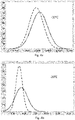
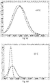
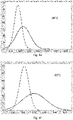
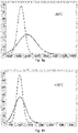
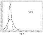
- Figures 4a-4i are graphs showing the distribution (in ordinate) of the optical fibre attenuation (as db/Km, in abscissa), at a wavelength of 1550 nm, in all the optical fibres of the optical fibre unit according to the present disclosure (dashed line) and in the optical fibres of the comparative optical cable unit (continuous line).
- the distribution is shown for different temperatures after two temperature cycles (the same fibres were used for all the cycles), particularly:
- the above-mentioned graphs show that during the first cycle the optical fibre attenuation of the optical cable unit of the present disclosure is slightly better than that of the comparative optical cable unit.
- the first cycle of tests is introductory to the second cycle, the results of the latter being the test bench for understanding the optical cable behaviour once installed.
- the optical fibre unit according to the present disclosure always showed a substantially better behaviour than that of the comparative optical cable unit.
- the curve representing the distribution of the optical attenuation in the optical fibres of the optical fibre unit according to the present disclosure is generally narrower than the one of the optical fibre unit of the known art, and this means a more uniform behaviour for the optical fibres in the units of the invention.
Landscapes
- Physics & Mathematics (AREA)
- General Physics & Mathematics (AREA)
- Optics & Photonics (AREA)
- Engineering & Computer Science (AREA)
- Manufacturing & Machinery (AREA)
- Optical Fibers, Optical Fiber Cores, And Optical Fiber Bundles (AREA)
- Percussion Or Vibration Massage (AREA)
- Compositions Of Macromolecular Compounds (AREA)
Abstract
Description
- The present disclosure relates to optical fibre units for air-blown installations.
- Fibre optic cables have been commonly deployed by blowing or pulling in ducts, by burying them in the ground, or suspending them between above-ground poles.
- Optical fibre units suitable for use in blown fibre systems typically comprise one or more optical fibres surrounded by an outer sheath, optionally bearing beads into its outer surface. The outer sheath is typically made of polymeric material, e.g. polyethylene. However, polymeric materials have a thermal coefficient of expansion (and contraction) higher than glass, potentially causing a significant (and sometimes excessive) cable contraction and optical fibre attenuation at low temperatures.
- Therefore, fibre reinforced polymer (FRP) as optical cable jacket material has been proposed to control the polymer material shrinkage. As reported, for example, by
US5561729 , short fibres are preferred over long fibres as less impacting the polymer material mechanical properties (particularly the stiffness), but they should be loaded in a greater amount than long fibres to obtain a significant shrinkage reduction. On the other hand, suitable amount of short fibres in polymer jacket material can provide a rough cable surface increasing the friction and thus reducing the potential cable blowing distance. - Several solutions are known in the art, which however do not relate to cables for air-blown installations.
- The just mentioned
US5561729 relates to telecommunications cables including elements (e.g. a sheath) made of a thermoplastic material which is reinforced by discontinuous reinforcement fibres made of materials such as glass. The reinforcement fibres each have a length of less than 0.2 cm (e.g. from around 0.02 cm to around 0.20 cm) and are incorporated in the thermoplastic material to reduce the coefficient of thermal expansion of the thermoplastic material. For reinforcement fibres of a length of around 0.02 cm to around 0.06 cm, the preferred maximum proportion by weight of the reinforcement fibres is about 25%. A reduction in the length of the reinforcement fibres used may have a substantial impact on tube brittleness. -
US9223103 -
US6400873 relates to fibre optic cables having at least one strength member. The strength member includes a matrix and a plurality of fibres disposed within the matrix. The matrix can be formed of a thermoset material. Alternatively, the matrix can be formed of a thermoplastic material, such as a polyolefin. Fibre optic cable also includes a protective jacket surrounding strength member. Protective jacket is formed of a plastic material. In one embodiment, strength member has a diameter of 2.0 mm and protective jacket has a diameter of 3.0 mm. - The Applicant therefore aims at providing an optical fibre unit for air-blown installations with a limited cable contraction (and expansion) and, consequently, a limited optical fibre attenuation, having a sufficient stiffness for the cable blowing, while maintaining at the same time a sufficient flexibility, a low coefficient of friction against the duct walls, and without impairing the duct cleanness.
- This aim is achieved by an optical fibre unit for air-blown installations comprising:
- one or more optical fibres;
- an outer jacket surrounding the one or more optical fibres, made of a fibre reinforced polymer comprising inorganic fibres embedded in a polymer matrix in an amount comprised between 5 and 25 wt% with respect to the weight of the fibre reinforced polymer, the inorganic fibres having a median length d50 comprised between 50 and 250 µm; and
- a skin layer surrounding the outer jacket and in direct contact thereto, the skin layer having a thickness comprised between 0.05 mm and 0.5 mm and being free from fibres.
- In the present description and claims, as optical fibre is meant a glass optical waveguide surrounded by a glass cladding to form the optical core. The optical core is surrounded by one or more protective layer, for example a primary and a secondary acrylate coating and, optionally, a buffer layer made of thermoplastic material.
- In an embodiment, the optical fibres are embedded in an inner layer made of polymeric material. The inner layer is surrounded and can be in direct contact with the outer sheath.
- In an embodiment, the outer jacket fibre reinforced polymer comprises inorganic fibres in an amount comprised between 10 and 20 wt% with respect to the weight of the fibre reinforced polymer.
- In the present description and claims, as median length (d50) is meant the medium value of the fibre length distribution, it is the value of the fibre length at 50% in the cumulative distribution.
- In an embodiment, the inorganic fibres of the present disclosure have a median length (d50) comprised between 100 and 200 µm.
- In an embodiment, the inorganic fibres have a diameter comprised between 14 and 16 µm.
- In an embodiment, the inorganic fibres comprise glass fibres.
- In an embodiment, the outer jacket polymer matrix is made of a material selected from polyethylene (PE), for example high-density polyethylene (HDPE), polyamide (PA) or polyester.
- In an embodiment, the outer jacket has a thickness comprised between 0.3 mm and 3 mm. The outer jacket is thicker than the skin layer.
- In an embodiment, the skin layer has a surface roughness lower than the surface roughness of the outer jacket.
- In an embodiment, the skin layer has a thickness of 0.1 to 0.3 mm.
- In an embodiment, the skin layer is made of a polymeric material selected from polyethylene (PE), polyamide (PA) or polyester.
- In an embodiment, the skin layer is made of a material including additives like lubricants or slipping agent for reducing the skin layer surface friction. Examples of suitable additives are waxes or fatty acid amides, like oleamide, erucamide and stearamide.
- Further characteristics and advantages will be more apparent from the following description of some embodiments given as a way of an example with reference to the attached drawings in which:
-
Figure 1 shows a sectional view of an optical fibre unit for air-blown installations according to an embodiment of the present disclosure; -
Figures 2a and 2b are graphs showing tensile stress (in ordinate) vs. elongation (in abscissa) of samples made of glass fibre filled HDPE and samples made of unfilled HDPE; -
Figures 3a and 3b are graphs showing flexural stress (in ordinate) vs. flexural strain (in abscissa) of samples made of glass fibre filled HDPE and samples made of unfilled HDPE; -
Figures 4a-4i are graphs showing the distribution of the optical fibre attenuation of the optical fibre unit according to an embodiment and in an optical cable according to the prior art. - For the purpose of the present description and of the appended claims, except where otherwise indicated, all numbers expressing amounts, quantities, percentages, and so forth, are to be understood as being modified in all instances by the term "about". Also, all ranges include any combination of the maximum and minimum points disclosed and include any intermediate ranges therein, which may or may not be specifically enumerated herein.
- The present disclosure, in at least one of the aforementioned aspects, can be implemented according to one or more of the following embodiments, optionally combined together.
- For the purpose of the present description and of the appended claims, the words "a" or "an" should be read to include one or at least one and the singular also includes the plural unless it is obvious that it is meant otherwise. This is done merely for convenience and to give a general sense of the disclosure.
-
Figure 1 shows an embodiment of anoptical fibre unit 1 according to the present disclosure. Theoptical fibre unit 1 is adapted for air-blown installations, as discussed in the introductory part of the present description. - The
optical fibre unit 1 comprises one or moreoptical fibres 2. In the example ofFigure 1 fouroptical fibres 2 are provided. However, in other examples (not shown) the number ofoptical fibres 2 could be higher or lower. It should be noticed that the number ofoptical fibres 2 is not relevant for the present invention and the number of optical fibres could be any number. - Each
optical fibre 2 ofFigure 1 comprises anoptical core 2a, aprotective coating system 2b and abuffer 2c. - The optical fibres suitable for the unit of the present disclosure may be single mode or multimode optical fibres. The optical fibres generally extend in a longitudinal direction. For example, the
optical fibres 2 are arranged in a bundle. - The
optical fibre unit 1 comprises anouter jacket 3 surrounding theoptical fibres 2. - The
outer jacket 3 is made of a fibre reinforced polymer comprising inorganic fibres embedded in a polymer matrix. The fibre reinforced polymer comprises the inorganic fibres in an amount comprised between 5 and 25 wt%, wherein "wt%" means the weight percentage of the inorganic fibres with respect to the total weight of the fibre reinforced polymer. In an embodiment, the amount of the inorganic fibres is comprised between 10 and 25 wt%, still more preferably between 15 and 20 wt%. - The inorganic fibres have a median length d50 comprised between 50 and 250 µm. As said above, the median length d50 is the value of the fibre length at 50% in the cumulative distribution. For example, when d50=100 µm, then 50% of the inorganic fibres in the polymer matrix are longer than 100 µm, and 50% are shorter than 100 µm. In an embodiment, the inorganic fibres have a median length d50 comprised between 100 and 200 µm.
- The inorganic fibres can comprise, for example, glass fibres. It is to be noted that two or more different types of inorganic fibres can be embedded in the polymer matrix.
- In an embodiment, the
outer jacket 3 has a thickness comprised between 0.3 mm and 3 mm. - In an embodiment, the
outer jacket 3 is based on a polymeric material like polyethylene, polyamide or polyester. - The Applicant has tested samples made of fibre reinforced polymer of the type used for the outer jacket of the optical fibre unit according to the present disclosure for evaluating the mechanical properties of the same compared to the mechanical properties of a polymeric sample of the type used for the outer jacket in a known optical fibre unit.
Figure 2a is a graph of tensile stress (as σ [MPa], in ordinate) vs. elongation (as ε [%], in abscissa) of five samples made of HDPE glass fibre filled according to the disclosure, andFigure 2b is an analogous graph of tensile stress vs. elongation of five samples made of the same HDPE, but unfilled. The tests have been performed according to IEC 60811-2-1 (2001) at a speed of 50.0 mm/min. As can be seen from the graphs in theFigures 2a and 2b , both for HDPE glass fibre filled according to the disclosure and for unfilled HDPE show a similar tensile behaviour and fracture occurs at about 700% of elongation, showing that the addition of inorganic fibres to the polymeric material does not substantially impair its mechanical properties. - Similar tests have been performed for evaluating the flexural properties. Particularly,
figure 3a is a graph of flexural stress (as σf [MPa], in ordinate vs. flexural strain (as εf [%], in ordinate) of three samples made of HDPE glass fibre filled according to the present disclosure, andFigure 3b is an analogous graph of flexural stress vs. flexural strain of three samples made of the same HDPE, but unfilled. The tests have been performed according to ASTM D790-10 at a speed of 1.20 mm/min. As can be seen from the graphs in theFigures 3a and 3b , both the HDPE glass fibre filled according to the present disclosure samples and the unfilled HDPE samples show a 3% flexural strain at a flexural stress of about 8 MPa, showing that the addition of inorganic fibres to the polymeric material does not substantially impair its mechanical properties. - Referring again to
Figure 1 , theoptical fibre unit 1 comprises askin layer 4 surrounding and in direct contact with theouter jacket 3. Theskin layer 4 has a thickness comprised between 0.05 mm and 0.5 mm. Preferably, the skin layer thickness is comprised between 0.1 mm and 0.3 mm. Theouter jacket 3 is thicker than theskin layer 4. - The
skin layer 4 has a surface roughness which is lower than the surface roughness of theouter jacket 3 containing inorganic fibres. This improves the optical fibre unit blowability because the friction between the duct wall and the optical fibre unit is reduced. - The
skin layer 4 can be made of a material like polyethylene (PE), polyamide (PA) or a polyester. In an embodiment, the material of theskin layer 4 is similar or the same as that of theouter jacket 3. - The
skin layer 4 material can include additives and/or lubricants for further reducing the above-mentioned friction. In an embodiment, the additives/lubricants can be selected from waxes or fatty acid amides. - The
skin layer 4 can be extruded over theouter jacket 3 or coextruded with the same. - The Applicant has tested an optical fibre unit according to the present disclosure for evaluating the optical fibre attenuation as a function of the temperature. Particularly, an optical fibre unit according to the present disclosure, having an outer jacket with glass fibres embedded in a HDPE matrix (with no skin layer as not relevant for the performance of the fibres as a function of the temperature), has been compared to a comparative optical fibre unit according to the known art having an unfilled HDPE outer jacket. The "optical fibre attenuation" is the reduction in intensity of the light beam with respect to distance travelled through the optical fibre.
-
Figures 4a-4i are graphs showing the distribution (in ordinate) of the optical fibre attenuation (as db/Km, in abscissa), at a wavelength of 1550 nm, in all the optical fibres of the optical fibre unit according to the present disclosure (dashed line) and in the optical fibres of the comparative optical cable unit (continuous line). The distribution is shown for different temperatures after two temperature cycles (the same fibres were used for all the cycles), particularly: - First cycle:
- @ -10°C (
Figure 4a ) - @ -20°C (
Figure 4b ) - @ +70°C (
figure 4c )
- @ -10°C (
- Second cycle:
- @ -10°C (
Figure 4d ) - @ -20°C (
Figure 4e ) - @ -30°C (
Figure 4f ) - @ -40°C (
Figure 4g ) - @ +70°C (
Figure 4h ) - @ +20°C (
Figure 4i )
- @ -10°C (
- The above-mentioned graphs show that during the first cycle the optical fibre attenuation of the optical cable unit of the present disclosure is slightly better than that of the comparative optical cable unit. The first cycle of tests is introductory to the second cycle, the results of the latter being the test bench for understanding the optical cable behaviour once installed. During the second cycle, the optical fibre unit according to the present disclosure always showed a substantially better behaviour than that of the comparative optical cable unit. In particular, the curve representing the distribution of the optical attenuation in the optical fibres of the optical fibre unit according to the present disclosure is generally narrower than the one of the optical fibre unit of the known art, and this means a more uniform behaviour for the optical fibres in the units of the invention. Also, according to the British Telecommunications specification CW1854 (2019) for air blown fiber, during test, maximum variation of fibre attenuation should be ≤0.10 dB/Km. As shown in Table I, the attenuation peak of the optical fibres in the unit of the invention varied of 0.06 dB/Km at most, while the attenuation peak of the optical fibers in the comparative unit varied of 0.11 dB/Km (thus unsuitable for the BT standard).
Table I Peak (mean value) (dB/Km) -10°C -20°C -30°C -40°C +70°C +20°C Dashed curve 0.19 0.20 0.21 0.24 0.19 0.18 Continuous curve 0.20 0.22 0.24 0.29 0.19 0.18
Claims (11)
- Optical fibre unit (1) comprising:- one or more optical fibres (2);- an outer jacket (3) surrounding the one or more optical fibres (2), made of a fibre reinforced polymer comprising inorganic fibres embedded in a polymer matrix in an amount comprised between 5 and 25 wt% with respect to the weight of the fibre reinforced polymer, the inorganic fibres having a median length (d50) comprised between 50 and 250 µm; and- a skin layer (4) surrounding the outer jacket (3) and in direct contact thereto, having a thickness comprised between 0.05 mm and 0.5 mm and being free from fibres.
- The optical fibre unit (1) of claim 1, wherein the outer jacket (3) fibre reinforced polymer comprises inorganic fibres in an amount comprised between 10 and 20 wt% with respect to the weight of the fibre reinforced polymer.
- The optical fibre unit (1) of claim 1, wherein the inorganic fibres have a median length (d50) comprised between 100 and 200 µm.
- The optical fibre unit (1) of claim 1, wherein the inorganic fibres diameter is comprised between 14 and 16 µm.
- The optical fibre unit (1) of claim 1, wherein the inorganic fibres comprise glass fibres.
- The optical fibre unit (1) of claim 1, wherein the outer jacket (3) polymer matrix is made of a material selected from polyethylene, polyamide or polyester.
- The optical fibre unit (1) of claim 1, wherein the outer jacket (3) has a thickness comprised between 0.3 mm and 3 mm, being the outer jacket (3) thicker than the skin layer (4).
- The optical fibre unit (1) of claim 1, wherein the skin layer (4) has a surface roughness which is lower than the surface roughness of the outer jacket (3).
- The optical fibre unit (1) of claim 1, wherein the skin layer (4) has a thickness of 0.1 to 0.3 mm.
- The optical fibre unit (1) of claim 1, wherein the skin layer (4) is made of a material selected from polyethylene, polyamide or polyester.
- The optical fibre unit (1) of claim 1, wherein the skin layer (4) includes additives for reducing the skin layer (4) surface frictions.
Applications Claiming Priority (1)
| Application Number | Priority Date | Filing Date | Title |
|---|---|---|---|
| IT102021000001742A IT202100001742A1 (en) | 2021-01-28 | 2021-01-28 | FIBER OPTIC UNIT FOR INSTALLATIONS BY AIR BLOWING |
Publications (1)
| Publication Number | Publication Date |
|---|---|
| EP4036622A1 true EP4036622A1 (en) | 2022-08-03 |
Family
ID=75252774
Family Applications (1)
| Application Number | Title | Priority Date | Filing Date |
|---|---|---|---|
| EP21217854.5A Pending EP4036622A1 (en) | 2021-01-28 | 2021-12-27 | Optical fibre unit for air-blown installations |
Country Status (5)
| Country | Link |
|---|---|
| US (1) | US11789224B2 (en) |
| EP (1) | EP4036622A1 (en) |
| CN (1) | CN114815096A (en) |
| AU (1) | AU2022200194A1 (en) |
| IT (1) | IT202100001742A1 (en) |
Citations (7)
| Publication number | Priority date | Publication date | Assignee | Title |
|---|---|---|---|---|
| US5561729A (en) | 1995-05-15 | 1996-10-01 | Siecor Corporation | Communications cable including fiber reinforced plastic materials |
| US6400873B1 (en) | 2000-03-31 | 2002-06-04 | Corning Cable Systems Llc | Fiber optic cable having a strength member |
| US20090250241A1 (en) * | 2006-05-22 | 2009-10-08 | Franco Galletti | Cable and process for manufacturing the same |
| US9223103B2 (en) | 2005-01-18 | 2015-12-29 | Commscope Technologies Llc | Low shrink telecommunications cable and methods for manufacturing the same |
| US20160274324A1 (en) * | 2013-11-29 | 2016-09-22 | Prysmian S.P.A. | High installation performance blown optical fibre unit, manufacturing method and apparatus |
| CN104614828B (en) * | 2015-03-10 | 2018-01-23 | 重庆成瑞光电科技有限公司 | Anti-bird pecking optical cable and manufacturing method thereof |
| US20190025531A1 (en) * | 2014-08-12 | 2019-01-24 | Prysmian S.P.A. | Optical cable and manufacturing method |
Family Cites Families (9)
| Publication number | Priority date | Publication date | Assignee | Title |
|---|---|---|---|---|
| DE3400202A1 (en) * | 1984-01-04 | 1985-07-11 | Siemens AG, 1000 Berlin und 8000 München | CABLE WITH FRICTION REDUCING OUTER LAYER |
| JP2571979B2 (en) * | 1990-11-20 | 1997-01-16 | 三菱電線工業株式会社 | Fiber optic cable |
| DE19500467A1 (en) * | 1995-01-05 | 1996-07-11 | Siemens Ag | Optical cable and method for recycling it |
| FR2760540B1 (en) * | 1997-03-10 | 1999-04-16 | Alsthom Cge Alcatel | OPTICAL FIBER CABLE TIGHTENED IN SHEATH |
| US6127632A (en) * | 1997-06-24 | 2000-10-03 | Camco International, Inc. | Non-metallic armor for electrical cable |
| US6487345B1 (en) * | 2000-01-12 | 2002-11-26 | Fitel Usa Corp. | Communication cable having reduced jacket shrinkage |
| US6853781B2 (en) * | 2001-08-13 | 2005-02-08 | Sumitomo Electric Lightwave Corp. | Air blown fiber (ABF) cable with low composite coefficient of thermal expansion |
| KR100628604B1 (en) * | 2004-03-02 | 2006-09-26 | 엘에스전선 주식회사 | Structure of pneumatically laid optical fiber and its manufacturing method and device |
| US20070236938A1 (en) * | 2006-03-31 | 2007-10-11 | 3M Innovative Properties Company | Structured Composite Optical Films |
-
2021
- 2021-01-28 IT IT102021000001742A patent/IT202100001742A1/en unknown
- 2021-12-27 EP EP21217854.5A patent/EP4036622A1/en active Pending
-
2022
- 2022-01-13 AU AU2022200194A patent/AU2022200194A1/en active Pending
- 2022-01-14 US US17/576,447 patent/US11789224B2/en active Active
- 2022-01-20 CN CN202210064291.5A patent/CN114815096A/en active Pending
Patent Citations (7)
| Publication number | Priority date | Publication date | Assignee | Title |
|---|---|---|---|---|
| US5561729A (en) | 1995-05-15 | 1996-10-01 | Siecor Corporation | Communications cable including fiber reinforced plastic materials |
| US6400873B1 (en) | 2000-03-31 | 2002-06-04 | Corning Cable Systems Llc | Fiber optic cable having a strength member |
| US9223103B2 (en) | 2005-01-18 | 2015-12-29 | Commscope Technologies Llc | Low shrink telecommunications cable and methods for manufacturing the same |
| US20090250241A1 (en) * | 2006-05-22 | 2009-10-08 | Franco Galletti | Cable and process for manufacturing the same |
| US20160274324A1 (en) * | 2013-11-29 | 2016-09-22 | Prysmian S.P.A. | High installation performance blown optical fibre unit, manufacturing method and apparatus |
| US20190025531A1 (en) * | 2014-08-12 | 2019-01-24 | Prysmian S.P.A. | Optical cable and manufacturing method |
| CN104614828B (en) * | 2015-03-10 | 2018-01-23 | 重庆成瑞光电科技有限公司 | Anti-bird pecking optical cable and manufacturing method thereof |
Also Published As
| Publication number | Publication date |
|---|---|
| IT202100001742A1 (en) | 2022-07-28 |
| CN114815096A (en) | 2022-07-29 |
| AU2022200194A9 (en) | 2022-10-27 |
| AU2022200194A1 (en) | 2022-08-11 |
| US11789224B2 (en) | 2023-10-17 |
| US20220236508A1 (en) | 2022-07-28 |
Similar Documents
| Publication | Publication Date | Title |
|---|---|---|
| US5561729A (en) | Communications cable including fiber reinforced plastic materials | |
| US9042693B2 (en) | Water-soluble water-blocking element | |
| EP1887396B1 (en) | Optical fibre telecommunication cable | |
| US20120014652A1 (en) | Adhesively Coupled Optical Fibers and Enclosing Tape | |
| EP2820462B1 (en) | Aerial optical fiber cables | |
| EP2284587B1 (en) | Tight-buffered optical fiber unit having improved accessibility | |
| US6546175B1 (en) | Self-supporting fiber optic cable | |
| US8486527B2 (en) | Compact, hybrid fiber reinforced rods for optical cable reinforcements and method for making same | |
| US20110091171A1 (en) | Optical-Fiber Cable Having High Fiber Count and High Fiber Density | |
| EP1646901A2 (en) | Fiber optic articles, assemblies, and cables having optical waveguides | |
| EP1895340B1 (en) | A loose tube optical waveguide fiber cable | |
| US5917978A (en) | Buffered optical fiber having improved low temperature performance and stripability | |
| EP2204681A1 (en) | Optical fibre cable comprising a perforated water-blocking element | |
| EP1063550A1 (en) | Polypropylene-polyethylene copolymer buffer tubes for optical fiber cables and method for making the same | |
| US7522795B2 (en) | Loose tube optical waveguide fiber cable | |
| US6778744B2 (en) | Dielectric optical fiber cable having reduced preferential bending | |
| NZ235615A (en) | Losses reduced in tubular cable core carrying overlength optical fibres | |
| GB2106266A (en) | Sheathed optical fiber cable | |
| WO2007019335A2 (en) | Mechanically strippable upcoated optical fiber | |
| EP3346307A1 (en) | Loose tube for optical fiber cable | |
| EP3180645B1 (en) | Optical cable and manufacturing method | |
| US6931190B2 (en) | Optical fiber unit for air blown fiber installation | |
| US5703984A (en) | Optical fiber cable with plural modular bundles of hermtically sealed optical fibers inside an outer cable sheath | |
| EP3955041A1 (en) | Air-blown optical fiber cable with flexible tubes | |
| US20140079361A1 (en) | Water-Swellable Element for Optical-Fiber Cables |
Legal Events
| Date | Code | Title | Description |
|---|---|---|---|
| PUAI | Public reference made under article 153(3) epc to a published international application that has entered the european phase |
Free format text: ORIGINAL CODE: 0009012 |
|
| STAA | Information on the status of an ep patent application or granted ep patent |
Free format text: STATUS: THE APPLICATION HAS BEEN PUBLISHED |
|
| AK | Designated contracting states |
Kind code of ref document: A1 Designated state(s): AL AT BE BG CH CY CZ DE DK EE ES FI FR GB GR HR HU IE IS IT LI LT LU LV MC MK MT NL NO PL PT RO RS SE SI SK SM TR |
|
| STAA | Information on the status of an ep patent application or granted ep patent |
Free format text: STATUS: REQUEST FOR EXAMINATION WAS MADE |
|
| 17P | Request for examination filed |
Effective date: 20230111 |
|
| RBV | Designated contracting states (corrected) |
Designated state(s): AL AT BE BG CH CY CZ DE DK EE ES FI FR GB GR HR HU IE IS IT LI LT LU LV MC MK MT NL NO PL PT RO RS SE SI SK SM TR |
|
| STAA | Information on the status of an ep patent application or granted ep patent |
Free format text: STATUS: EXAMINATION IS IN PROGRESS |
|
| 17Q | First examination report despatched |
Effective date: 20241218 |