EP4036604A1 - Laser irradiation apparatus - Google Patents
Laser irradiation apparatus Download PDFInfo
- Publication number
- EP4036604A1 EP4036604A1 EP22162930.6A EP22162930A EP4036604A1 EP 4036604 A1 EP4036604 A1 EP 4036604A1 EP 22162930 A EP22162930 A EP 22162930A EP 4036604 A1 EP4036604 A1 EP 4036604A1
- Authority
- EP
- European Patent Office
- Prior art keywords
- laser
- target
- laser light
- dealing
- light
- Prior art date
- Legal status (The legal status is an assumption and is not a legal conclusion. Google has not performed a legal analysis and makes no representation as to the accuracy of the status listed.)
- Granted
Links
Images



Classifications
-
- F—MECHANICAL ENGINEERING; LIGHTING; HEATING; WEAPONS; BLASTING
- F41—WEAPONS
- F41H—ARMOUR; ARMOURED TURRETS; ARMOURED OR ARMED VEHICLES; MEANS OF ATTACK OR DEFENCE, e.g. CAMOUFLAGE, IN GENERAL
- F41H13/00—Means of attack or defence not otherwise provided for
- F41H13/0043—Directed energy weapons, i.e. devices that direct a beam of high energy content toward a target for incapacitating or destroying the target
- F41H13/005—Directed energy weapons, i.e. devices that direct a beam of high energy content toward a target for incapacitating or destroying the target the high-energy beam being a laser beam
- F41H13/0062—Directed energy weapons, i.e. devices that direct a beam of high energy content toward a target for incapacitating or destroying the target the high-energy beam being a laser beam causing structural damage to the target
-
- G—PHYSICS
- G01—MEASURING; TESTING
- G01S—RADIO DIRECTION-FINDING; RADIO NAVIGATION; DETERMINING DISTANCE OR VELOCITY BY USE OF RADIO WAVES; LOCATING OR PRESENCE-DETECTING BY USE OF THE REFLECTION OR RERADIATION OF RADIO WAVES; ANALOGOUS ARRANGEMENTS USING OTHER WAVES
- G01S17/00—Systems using the reflection or reradiation of electromagnetic waves other than radio waves, e.g. lidar systems
- G01S17/02—Systems using the reflection of electromagnetic waves other than radio waves
- G01S17/06—Systems determining position data of a target
- G01S17/42—Simultaneous measurement of distance and other co-ordinates
-
- G—PHYSICS
- G01—MEASURING; TESTING
- G01S—RADIO DIRECTION-FINDING; RADIO NAVIGATION; DETERMINING DISTANCE OR VELOCITY BY USE OF RADIO WAVES; LOCATING OR PRESENCE-DETECTING BY USE OF THE REFLECTION OR RERADIATION OF RADIO WAVES; ANALOGOUS ARRANGEMENTS USING OTHER WAVES
- G01S17/00—Systems using the reflection or reradiation of electromagnetic waves other than radio waves, e.g. lidar systems
- G01S17/66—Tracking systems using electromagnetic waves other than radio waves
-
- G—PHYSICS
- G01—MEASURING; TESTING
- G01S—RADIO DIRECTION-FINDING; RADIO NAVIGATION; DETERMINING DISTANCE OR VELOCITY BY USE OF RADIO WAVES; LOCATING OR PRESENCE-DETECTING BY USE OF THE REFLECTION OR RERADIATION OF RADIO WAVES; ANALOGOUS ARRANGEMENTS USING OTHER WAVES
- G01S17/00—Systems using the reflection or reradiation of electromagnetic waves other than radio waves, e.g. lidar systems
- G01S17/88—Lidar systems specially adapted for specific applications
- G01S17/89—Lidar systems specially adapted for specific applications for mapping or imaging
-
- G—PHYSICS
- G01—MEASURING; TESTING
- G01S—RADIO DIRECTION-FINDING; RADIO NAVIGATION; DETERMINING DISTANCE OR VELOCITY BY USE OF RADIO WAVES; LOCATING OR PRESENCE-DETECTING BY USE OF THE REFLECTION OR RERADIATION OF RADIO WAVES; ANALOGOUS ARRANGEMENTS USING OTHER WAVES
- G01S7/00—Details of systems according to groups G01S13/00, G01S15/00, G01S17/00
- G01S7/48—Details of systems according to groups G01S13/00, G01S15/00, G01S17/00 of systems according to group G01S17/00
- G01S7/481—Constructional features, e.g. arrangements of optical elements
- G01S7/4814—Constructional features, e.g. arrangements of optical elements of transmitters alone
- G01S7/4815—Constructional features, e.g. arrangements of optical elements of transmitters alone using multiple transmitters
-
- H—ELECTRICITY
- H01—ELECTRIC ELEMENTS
- H01S—DEVICES USING THE PROCESS OF LIGHT AMPLIFICATION BY STIMULATED EMISSION OF RADIATION [LASER] TO AMPLIFY OR GENERATE LIGHT; DEVICES USING STIMULATED EMISSION OF ELECTROMAGNETIC RADIATION IN WAVE RANGES OTHER THAN OPTICAL
- H01S5/00—Semiconductor lasers
- H01S5/10—Construction or shape of the optical resonator, e.g. extended or external cavity, coupled cavities, bent-guide, varying width, thickness or composition of the active region
- H01S5/18—Surface-emitting [SE] lasers, e.g. having both horizontal and vertical cavities
- H01S5/183—Surface-emitting [SE] lasers, e.g. having both horizontal and vertical cavities having only vertical cavities, e.g. vertical cavity surface-emitting lasers [VCSEL]
- H01S5/18386—Details of the emission surface for influencing the near- or far-field, e.g. a grating on the surface
-
- H—ELECTRICITY
- H01—ELECTRIC ELEMENTS
- H01S—DEVICES USING THE PROCESS OF LIGHT AMPLIFICATION BY STIMULATED EMISSION OF RADIATION [LASER] TO AMPLIFY OR GENERATE LIGHT; DEVICES USING STIMULATED EMISSION OF ELECTROMAGNETIC RADIATION IN WAVE RANGES OTHER THAN OPTICAL
- H01S5/00—Semiconductor lasers
- H01S5/40—Arrangement of two or more semiconductor lasers, not provided for in groups H01S5/02 - H01S5/30
- H01S5/4025—Array arrangements, e.g. constituted by discrete laser diodes or laser bar
- H01S5/4031—Edge-emitting structures
- H01S5/4056—Edge-emitting structures emitting light in more than one direction
-
- H—ELECTRICITY
- H01—ELECTRIC ELEMENTS
- H01S—DEVICES USING THE PROCESS OF LIGHT AMPLIFICATION BY STIMULATED EMISSION OF RADIATION [LASER] TO AMPLIFY OR GENERATE LIGHT; DEVICES USING STIMULATED EMISSION OF ELECTROMAGNETIC RADIATION IN WAVE RANGES OTHER THAN OPTICAL
- H01S5/00—Semiconductor lasers
- H01S5/50—Amplifier structures not provided for in groups H01S5/02 - H01S5/30
-
- H—ELECTRICITY
- H01—ELECTRIC ELEMENTS
- H01S—DEVICES USING THE PROCESS OF LIGHT AMPLIFICATION BY STIMULATED EMISSION OF RADIATION [LASER] TO AMPLIFY OR GENERATE LIGHT; DEVICES USING STIMULATED EMISSION OF ELECTROMAGNETIC RADIATION IN WAVE RANGES OTHER THAN OPTICAL
- H01S5/00—Semiconductor lasers
- H01S5/02—Structural details or components not essential to laser action
- H01S5/022—Mountings; Housings
- H01S5/023—Mount members, e.g. sub-mount members
- H01S5/02325—Mechanically integrated components on mount members or optical micro-benches
- H01S5/02326—Arrangements for relative positioning of laser diodes and optical components, e.g. grooves in the mount to fix optical fibres or lenses
-
- H—ELECTRICITY
- H01—ELECTRIC ELEMENTS
- H01S—DEVICES USING THE PROCESS OF LIGHT AMPLIFICATION BY STIMULATED EMISSION OF RADIATION [LASER] TO AMPLIFY OR GENERATE LIGHT; DEVICES USING STIMULATED EMISSION OF ELECTROMAGNETIC RADIATION IN WAVE RANGES OTHER THAN OPTICAL
- H01S5/00—Semiconductor lasers
- H01S5/10—Construction or shape of the optical resonator, e.g. extended or external cavity, coupled cavities, bent-guide, varying width, thickness or composition of the active region
- H01S5/18—Surface-emitting [SE] lasers, e.g. having both horizontal and vertical cavities
- H01S5/183—Surface-emitting [SE] lasers, e.g. having both horizontal and vertical cavities having only vertical cavities, e.g. vertical cavity surface-emitting lasers [VCSEL]
- H01S5/18344—Surface-emitting [SE] lasers, e.g. having both horizontal and vertical cavities having only vertical cavities, e.g. vertical cavity surface-emitting lasers [VCSEL] characterized by the mesa, e.g. dimensions or shape of the mesa
Definitions
- the present invention relates to a laser irradiation apparatus and a storage medium that stores a laser irradiation program.
- Patent Literature 1 discloses a technology of irradiating high-power continuous wave laser light to destroy a target.
- An apparatus described in the Patent Literature 1 converts high-power continuous wave laser light to pulse laser light by pulse converter and irradiates the converted laser light to the target.
- An optical sensor receives reflected light of this laser light and detects the target.
- a controller stops pulse conversion process of the pulse converter so that continuous wave laser light is irradiated to the target and the target is destroyed.
- Patent Literature 2 discloses a technology of changing laser irradiation direction by wavelength.
- An apparatus described in the Patent Literature 2 is provided with a waveguide having two distributed Bragg reflection mirrors, a light incident port for incident light in the waveguide and a light emission port for emitting light that is guided in the waveguide.
- Patent Literature 3 discloses a technology of changing irradiation direction of high-power laser non-mechanically.
- the apparatus disclosed in the Patent Literature 3 is provided with a first vertical cavity surface emitting laser (VCSEL) long in a first direction and a driving circuit that injects current to the first VCSEL.
- VCSEL vertical cavity surface emitting laser
- Incident light that incidents in the incident port provided at an end in the first direction of the first VCSEL, travels inside the first VCSEL along the first direction, while being reflected in a vertical direction, and is emitted from the emitting port on an upper surface of the first VCSEL as emission light. It is disclosed that a direction in which this emission light is emitted is inclined to the first direction from a normal direction of the emitting port based on a wavelength of the incident light and the like.
- the present invention has been made in view of the above circumstances and one objective thereof is to provide a laser irradiation apparatus that efficiently carries out processes such as detection of target by use of laser light.
- Other objectives will be understood from following disclosures and explanations of embodiments.
- the laser irradiation apparatus is provided with a laser array, a detector and a controller.
- the laser array is provided with a plurality of laser oscillators including a first laser oscillator that irradiates first detection laser light and a second laser oscillator that irradiates second dealing laser light.
- the detector obtains detection information based on reflected light that is the first detection laser light reflected by a target.
- the controller estimates a position of the target based on the detection information and generate a second dealing signal that instructs the second laser oscillator to irradiate the second dealing laser light to the estimated position of the target.
- the second laser oscillator irradiates the second dealing laser light to the estimated position of the target based on the second dealing signal.
- the laser irradiation apparatus is provided with a laser array with a plurality of laser oscillators arranged in an array.
- the plurality of laser oscillators is provided with a first laser oscillator group including a part of laser oscillators of the plurality of laser oscillators and a second laser oscillator group including a part of laser oscillators of the plurality of laser oscillators.
- the first laser oscillator group irradiates a first laser light group in a first direction to display a first image in the first direction.
- the second laser oscillator group irradiates a second laser light group in a second direction different from the first direction to display a second image in the second direction.
- a storage medium that stores a laser irradiation program is a non-transitory storage medium that stores a program which controls a first laser oscillator and a second laser oscillator arranged in a laser array , the program including a step of generating a detection signal that instructs the first laser oscillator to irradiate detection laser light and a step of generating, based on detection information obtained by receiving reflected light that is the detection laser light reflected by a target, a dealing signal that instructs the second laser oscillator to irradiate dealing laser light to the target.
- a process such as detection of a target is efficiently carried out.
- a laser irradiation apparatus 1 is configured to detect a target 2 by use of output laser light 501 and destroy the target 2. As shown in Fig. 1 , the laser irradiation apparatus 1 is provided with a laser array 10, a detector 20 and a controller 30.
- the laser array 10 is formed with a plurality of laser oscillators 11 that irradiate output laser light 501 and are arranged in an array on a surface thereof.
- the laser oscillators 11 may be regularly arranged, in a grid pattern for example.
- the laser oscillator 11 may be arranged irregularly.
- the laser oscillators 11 are arranged in the laser array 10 at a high density: for example, 400 or more laser oscillators 11 are arranged per square meter.
- the laser oscillators 11 may be arranged at a density of ten thousand or more per square.
- the laser oscillators 11 can arbitrarily change a direction of irradiating the output laser light 501.
- the laser oscillator 11 change the direction of irradiating the output laser light 501 non-mechanically and two-dimensionally.
- the target 2 reflects the output laser light 501 as reflected light 503. Detail of the laser oscillator 11 will be described later.
- the detector 20 receives the reflected light 503 reflected by the target 2 and obtains detection information such as an image in which the target 2 is taken.
- the detector 20 includes an optical camera such as a visible ray camera, an infrared ray camera and an ultraviolet ray camera, and takes an image of the target 2 irradiated by the output laser light 501.
- the detector 20 obtains an image in which the target 2 is taken as detection information and transmits it to the controller 30.
- the detector 20 may select an arbitrary device to detect the reflected light 503.
- the controller 30 estimates a position of the target 2 based on the detection information such as the image obtained by the detector 20.
- the controller 30 extracts a location in the image taken by the detector 20 where the target 2 is shown.
- the controller 30 estimates the position of the target 2 based on the direction in which the detector 20 has taken the image and the location where the target 2 is shown in the image that has been taken.
- the controller 30 transmits to the plurality of laser oscillators 11 a request to irradiate the output laser light 501 to the estimated position of the target 2.
- the plurality of laser oscillators 11 irradiate the output laser light 501 to the estimated positions of the target 2. For example, all of the laser oscillators 11 that can irradiate to the position of the target 2 may irradiate the output laser light 501 to the position of the target 2. At the position of the target 2, energy of the output laser light 501 is increased by overlaying the output laser light 501 irradiated by the plurality of laser oscillators 11. As a result, the laser irradiation apparatus 1 can destroy the target 2. For this reason, the output laser light 501 irradiated by the laser oscillators 11 may have phases that interfere so that energies of the output laser light 501 strengthen each other at the position of the target 2. In this case, the phase of the output laser light 501 irradiated by each laser oscillator 11 is instructed by the controller 30.
- the laser irradiation apparatus 1 can irradiate output laser light 501 as detection laser light to detect a target 2 and irradiate to the target 2 a plurality of beams of the output laser light 501 as dealing laser light to attack the detected target 2. For this reason, detection of the target 2 and attack on the target 2 can be efficiently performed.
- the laser array 10 may be provided with a laser oscillator 11 that can irradiate only detection laser light.
- the laser array 10 may be provided with a laser oscillator 11 that can irradiate only dealing laser light. All laser oscillators 11 included in the laser array 10 may be configured to be able to irradiate detection laser light and dealing laser light.
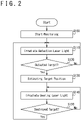
- the laser irradiation apparatus 1 carries out processes shown in Fig. 2 .
- the detector 20 starts a monitoring such as taking images for detecting the target 2 and obtains detection information.
- a direction in which the detector 20 detects for example a direction of taking image, may be determined based on an instruction from the controller 30.
- the direction in which the detector 20 detects may be fixed to a predetermined direction.
- a laser oscillator 11 irradiates output laser light 501 as detection laser light.
- the controller 30 determines the laser oscillator 11 which irradiates the detection laser light and generates a detection signal which indicates to the determined laser oscillator 11 to irradiate the detection laser light.
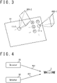
- the laser oscillator 11 that is to irradiate the detection laser light one of the laser oscillators 11 that can irradiate detection laser light to a detection space 600 to be detected may be selectively determined. For example, as shown in Fig. 3 , the controller 30 transmits a detection signal to a first laser oscillator 11-1 and a second laser oscillator 11-2 of the plurality of laser oscillators 11.
- a direction of irradiating the detection laser light is indicated in the detection signal.
- the first laser oscillator 11-1 irradiates detection laser light to a first detection space 600-1 based on the received detection signal.
- the second laser oscillator 11-2 irradiates detection laser light to a second detection space 600-2 based on the received detection signal.
- the first detection space 600-1 and the second detection space 600-2 are different spaces.
- a single laser oscillator 11 may irradiate detection laser light.
- step S120 the controller 30 determines whether information of the target 2 is included in the detection information obtained by the detector 20. For example, the controller 30 determines that information of the target 2 is included when there is in an image taken by the detector 20 an area brighter than a predetermined threshold value. When it is determined that the information of the target 2 is included in the detection information, the process proceeds to step S130. When it is determined that the information of the target 2 is not included in the detection information, the process returns to step S110 and the process is repeated until the target 2 is detected.
- step S130 the controller 30 estimates a position of the target 2 based on the detection information. For example, when the laser irradiation apparatus 1 is provided with a plurality of detectors 20, the controller 30 extracts the location in which the target 2 is shown from the image taken by each of the detectors 20. A target direction 601 from the detector 20 toward the target 2 is estimated based on the extracted position of the target 2 and the direction in which the detector 20 takes image. As shown in Fig. 4 , the controller 30 estimates a location in which a straight line elongated along the target direction 601 from each detector 20 toward the target 2 crosses as the position of the target 2.
- the controller 30 estimates a distance from the detector 20 to the target 2 based on a time from when the laser oscillator 11 irradiates the detection laser light to when the detector 20 receives reflected light 503.
- the target direction 601 from the detector 20 toward the target 2 is estimated based on the detection information obtained by the detector 20.
- the controller 30 estimates the position of the target 2 based on the distance from the detector 20 to the target 2 and the target direction 601.
- step S140 the controller 30 controls the laser oscillator 11 and irradiates output laser light 501 as dealing laser light to the target 2.
- the controller 30 determines a plurality of laser oscillators 11 that irradiate dealing laser light and transmits dealing signal for irradiating dealing laser light to the position of the target 2 estimated in step S130 to the determined plurality of laser oscillators 11.
- the laser oscillators 11 are specified by the dealing signal in the direction of irradiating the dealing laser light and irradiate the dealing laser light in the specified direction.
- the dealing laser light irradiated by the laser oscillators 11 is overlayed on the target 2 and destroys the target 2.
- the laser oscillator 11 that irradiates the dealing laser light is determined based on the position of the target 2.
- all of those laser oscillators 11 may irradiate the dealing laser light to the target 2.
- a part of those laser oscillators 11, for example laser oscillators 11 of which irradiation angle is equal to or less than 30 degrees, may irradiate the dealing laser light to the target 2.
- the irradiation angle indicates an angle between a direction from a laser oscillator 11 toward a center of a space to which the laser oscillator 11 can irradiate output laser light 501 and an irradiation direction of the output laser light 501.
- a laser oscillator 11 that does not irradiate dealing laser light may irradiate detection laser light as an operation in step S110.
- the space to which the detection laser light is irradiated may be overlayed to a space in which the laser oscillator 11, that is irradiating dealing laser light, was irradiating detecting laser light.
- the space to which this detection laser light is irradiated may include the space in which the laser oscillator 11, that is irradiating dealing laser light, was irradiating detection laser light.
- the laser oscillator 11 changes a location to irradiate dealing laser light in accordance with a movement of the target 2.
- the detector 20 obtains detection information while the laser oscillator 11 is irradiating dealing laser light. Since the target 2 reflects the dealing laser light as reflected light 503, information of the target 2 is included in the detection information.
- the controller 30 estimates the position of the target 2 based on this detection information, similarly to step S130. Dealing signal with updated position of the target 2 is transmitted to the laser oscillator 11 that is already determined.
- the laser oscillator 11 irradiates dealing laser light to the updated position of the target 2.
- the position of the target 2 may be estimated by irradiating detection laser light to the target 2 from a laser oscillator 11 that has not irradiated dealing laser light.
- step S150 the controller 30 determines whether the target 2 is destroyed.
- the controller 30 verifies whether the target 2 exists at the estimated position of the target 2, based on detection information obtained by the detector 20. For example, the controller 30 determines whether information of the target 2 is included in the detection information, similarly to step S120. When no information of the target 2 is included in the detection information, the controller 30 determines that the target 2 is destroyed. When information of the target 2 is included in the detection information, the position of the target 2 is estimated, similarly to step S130. When the location to which the laser oscillator 11 is irradiating dealing laser light, is not included in the estimated position of the target 2, the controller 30 determines that the target 2 is destroyed.
- the controller 30 determines that the target 2 is not destroyed.
- the process returns to step S140 and the laser oscillator 11 continues irradiating the dealing laser light to the target 2.
- the process returns to step S110 and the laser oscillator 11 irradiates detection laser light.
- the laser irradiation apparatus 1 performs detection and destruction of target 2 by irradiating detection laser light and dealing laser light from laser oscillators 11. Energy of the detection laser light may be smaller than energy of the dealing laser light.
- the laser irradiation apparatus 1 may irradiate dealing laser light to a plurality of targets 2.
- information of a first target 2-1 and a second target 2-2 is included in the detection information that the detector 20 obtains.
- the controller 30 estimates a position of the first target 2-1 and a position of the second target 2-2, based on the detection information.
- the controller 30 determines a laser oscillator 11 that irradiates dealing laser light to the first target 2-1 based on the estimated position of the first target 2-1 and determines a laser oscillator 11 that irradiates dealing laser light to the second target 2-2 based on the estimated position of the second target 2-2.
- the controller 30 transmits a dealing signal for irradiating dealing laser light to the targets 2 to each laser oscillator 11.
- the laser oscillators 11 irradiate dealing laser light to the first target 2-1 or the second target 2-2, based on the dealing signal.
- the controller 30 determines a target 2 to assign to this laser oscillator 11. For example, the controller 30 may assign a target 2 of which irradiation angle becomes smallest to the laser oscillator 11.
- a target 2 may be assigned to the laser oscillator 11 so that a number of laser oscillators 11 that irradiates dealing laser light to the first target 2-1 becomes equal to a number of laser oscillators 11 that irradiates dealing laser light to the second target 2-2.
- the controller 30 may estimate target information such as a position, a speed, an acceleration and a traveling direction of the target 2 based on the detection information that the detector 20 has obtained, and may determine the target 2 to assign to the laser oscillator 11. For example, the controller 30 may assign a target 2 of which a distance from the laser irradiation apparatus 1 is the shortest to the laser oscillator 11. Based on a position and a speed of the target 2, a target 2 that reaches the laser irradiation apparatus 1 the fastest may be assigned to the laser oscillator 11. To estimate a speed or the like of the target 2, at first, the controller 30 estimates a position of the target 2 at each time based on detection information that the detector 20 has obtained at different times.
- target information such as a position, a speed, an acceleration and a traveling direction of the target 2 based on the detection information that the detector 20 has obtained, and may determine the target 2 to assign to the laser oscillator 11. For example, the controller 30 may assign a target 2 of which a distance from the laser i
- the controller 30 estimates the speed or the like of the target 2 based on the times at which the detector 20 has obtained the detection information and a position of the target 2 at each time.
- the controller 30 may assign a target 2 of which a distance from the facilities to protect is the closest to the laser oscillator 11.
- the target 2 that reaches the facilities to protect the fastest may be assigned to the laser oscillator 11.
- the target information may include types of moving objects such as aircraft, drone, flying object and vehicle.
- the controller 30 may estimate a type of the target 2 such as aircraft, drone, flying object and vehicle based on the detection information that the detector 20 has obtained and may determine the target 2 to assign to the laser oscillator 11. In this case, the controller 30 estimates a shape of the target 2 based on the detection information that the detector 20 has obtained.
- the controller 30 searches for a registered shape that is the closest to the estimated shape in registered shapes that are registered.
- the type that corresponds to the registered shape that is searched is estimated as the type of the target 2.
- a priority that corresponds to the estimated type is searched and a target 2 of which the priority is the highest is assigned to the laser oscillator 11.
- registered shapes, types and priorities are registered in association in the controller 30.
- a use, a model and the like of moving objects may be included in the target information.
- the priority is set to the use, the model and the like of the moving objects.
- the controller 30 may calculate a threat level of the target 2 based on the detection information that the detector 20 has obtained and may assign a target 2 of which the threat level is the highest to the laser oscillator 11.
- the threat level is calculated based on a type, a size, a speed, a traveling direction and the like of the target 2.
- the controller 30 may be provided with an input device and may assign a target 2 selected by a user to the laser oscillator 11.
- the controller 30 may change a laser oscillator 11 that irradiates dealing laser light in accordance with the movement of the target 2.
- a laser oscillator 11 that irradiates dealing laser light in accordance with the movement of the target 2.
- it will be described by use of a cartesian coordinate system. It will be described with x direction and y direction as in-plane directions of the surface of the laser array 10 and z direction as normal direction of the surface of the laser array 10.
- the controller 30 assigns the target 2 to the second laser oscillator 11-2 that is arranged in +x direction from the first laser oscillator 11-1 that is irradiating dealing laser light to the target 2.
- the controller 30 stops the irradiation of the dealing laser light by the first laser oscillator 11-1.
- the controller 30 assigns the target 2 to the third laser oscillator 11-3 that is arranged in +x direction from the second laser oscillator 11-2 that is irradiating dealing laser light to the target 2.
- the controller 30 stops the irradiation of the dealing laser light by the second laser oscillator 11-2.
- the laser oscillators 11 operate as following. As shown in Fig. 7 , irradiation oscillators 11a of the laser oscillators 11 are irradiating dealing laser light to the target 2. Adjacent oscillators 11b of the laser oscillators 11, that are arranged in an adjacent area 12 that is adjacent to the irradiation oscillators 11a, are not irradiating dealing laser light.
- a part of the adjacent oscillators 11b irradiates dealing laser light to the target 2.
- a first adjacent oscillator 11b-1 arranged in +x direction from the irradiation oscillators 11a can irradiate dealing laser light to the target 2 with an angle with which the irradiation oscillators 11a were irradiating.
- the controller 30 generates dealing signal so that the first adjacent oscillator 11b-1 irradiates dealing laser light to the target 2.
- the first adjacent oscillator 11b-1 irradiates dealing laser light to the target 2 based on the dealing signal.
- a part of the irradiation oscillators 11a stops the irradiation of the dealing laser light.
- a first irradiation oscillator 11a-1 which is arranged in -x direction that is a direction opposite to the movement direction of the target 2, cannot irradiate dealing laser light to the target 2 with the angle with which the irradiation oscillators 11a were irradiating.
- the controller 30 generates dealing signal for the first irradiation oscillator 11a-1 so as to stop the irradiation of the dealing laser light.
- the first irradiation oscillator 11a-1 stops the irradiation of the dealing laser light based on the dealing signal.
- the first adjacent oscillator 11b-1 may irradiate dealing laser light before the first irradiation oscillator 11a-1 stops the irradiation of the dealing laser light. In addition, the first adjacent oscillator 11b-1 may irradiate dealing laser light after the first irradiation oscillator 11a-1 stopped the irradiation of the dealing laser light. The first adjacent oscillator 11b-1 may irradiate dealing laser light at a same time as the first irradiation oscillator 11a-1 stops the irradiation of the dealing laser light.
- the controller 30 may generate a dealing signal to transmit to the first adjacent oscillator 11b-1 before generating a dealing signal to transmit to the first irradiation oscillator 11a-1.
- the controller 30 may generate a dealing signal to transmit to the first adjacent oscillator 11b-1 after generating a dealing signal to transmit to the first irradiation oscillator 11a-1.
- the controller 30 may generate a dealing signal to transmit to the first adjacent oscillator 11b-1 at a same time as generating a dealing signal to transmit to the first irradiation oscillator 11a-1.
- An adjacent oscillator 11b arranged in the adjacent area 12 may be controlled so as not to irradiate detection laser light. It can be said that an adjacent oscillator 11b is a laser oscillator 11 with high probability of irradiating dealing laser light to the target 2. An irradiation direction of detection laser light is controlled so that detection laser light is irradiated to entire detection space 600. By controlling an adjacent oscillator 11b not to irradiate detection laser light, it is suppressed from starting irradiation of dealing laser light while irradiating detection laser light to the detection space 600. A shape of the adjacent area 12 may be changed in accordance with a traveling direction, a speed, an acceleration or the like of the target 2.
- the controller 30 can control the laser oscillator 11 in a case in which the target 2 moves in y direction or the like, as in the case of movement in x direction.
- the controller 30 may estimate an estimation path 3 of the target 2 based on the detection information and may determine a laser oscillator 11 that irradiates dealing laser light to the target 2 based on the estimation path 3.
- Laser oscillators 11 that are irradiating dealing laser light to the target 2 are arranged in an irradiation area 13.
- the controller 30 estimates the estimation path 3 of the target 2. For example, target information such as a position, a speed, an acceleration and a model of the target 2 is estimated based on the detection information that the detector 20 has obtained.
- the estimation path 3 of the target 2 is estimated based on the estimated target information of the target 2.
- the controller 30 determines a laser oscillator 11 that irradiates dealing laser light to the target 2 at desired times, based on the estimation path 3. For example, the controller 30 estimates estimation positions 4 of the target 2 at the desired times, such as a first estimation position 4-1 and a second estimation position 4-2, based on the estimation path 3 of the target 2.
- estimation positions 4 of the target 2 at the desired times such as a first estimation position 4-1 and a second estimation position 4-2, based on the estimation path 3 of the target 2.
- a laser oscillator 11 that irradiates dealing laser light when the target 2 reaches the first estimation position 4-1 (for example, a laser oscillator 11 arranged in a first estimation irradiation area 14-1) is determined based on the first estimation position 4-1.
- a laser oscillator 11 that irradiates dealing laser light when the target 2 reaches the second estimation position 4-2 is determined based on the second estimation position 4-2.
- the controller 30 determines a schedule for the laser oscillator 11 to irradiate dealing laser light to the target 2 and controls the laser oscillator 11 based on the schedule.
- the controller 30 determines a schedule for each laser oscillator 11 to irradiate dealing laser light, based on times when the target 2 reaches the estimation positions 4 and the laser oscillators 11 arranged in the estimation irradiation areas 14.
- the controller 30 generates dealing signal to control the laser oscillators 11, according to this schedule. For example, the dealing signal is transmitted to the laser oscillators 11 arranged in the first estimation irradiation area 14-1 at a time when the target 2 reaches the first estimation position 4-1. As a result, the laser oscillators 11 irradiate dealing laser light to the target 2 in accordance with the determined schedule.
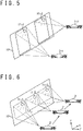
- the controller 30 may determine the schedule for the laser oscillators 11 to irradiate dealing laser light to the target 2 by estimating the estimation path 3 of the target 2. This schedule may be updated when the detector 20 obtains the detection information. As shown in Fig. 5 , when a plurality of targets 2 are detected, a laser oscillator 11 that irradiates dealing laser light to each target 2 may be determined.
- the controller 30 may select laser oscillators 11 that irradiate detection laser light so that an image such as letters or diagram is displayed on the laser array 10. For example, the controller 30 determines an area in accordance with the shape of the letters "AAA" in the laser array 10 (for example, an area occupied by the letters, an area occupied by edges of the letters or the like). The controller 30 selects the laser oscillators 11 arranged in this area as a laser oscillator group and transmits detection signal that instructs the selected laser oscillator group to irradiate detection laser light. The laser oscillators 11 included in the laser oscillator group irradiate output laser light 501 as detection laser light, based on the detection signal.
- a laser light group including output laser light 501 irradiated by each laser oscillator 11 is irradiated.
- the letters "AAA" are displayed.
- the laser oscillators 11 irradiate detection laser light
- the detection laser light is reflected by the target 2 and reaches the detector 20.
- the detector 20 can detect the target 2.
- the laser array 10 can detect the target 2 by displaying letters.
- a direction of irradiating detection laser light can be arbitrarily selected in accordance with a direction of displaying an image on the laser array 10. For example, when displaying an image to a plurality of directions, corresponding laser oscillators 11 irradiate detection laser light to the plurality of directions. For example, by setting an interval of irradiating detection laser light to a predetermined direction to 1/25 second, an image on the laser array 10 is displayed when viewing the laser array 10 from this direction.
- other laser oscillators 11 thereof may irradiate detection laser light to a direction different from the first direction.
- the controller 30 may change the image displayed on the laser array 10 in accordance with a direction of viewing the laser array 10.
- the controller 30 controls the laser oscillators 11 so as to irradiate the laser light group, in accordance with the shape of a string of letters "AAA", in the first direction.
- the controller 30 determines an area on the laser array 10 in accordance with the shape of the string of letters "AAA” and selects the laser oscillators 11 arranged in this area as the first laser oscillator group.
- the selected first laser oscillator group irradiates a first output laser light 501-1 as detection laser light in the first direction, in accordance with the instruction from the controller 30.
- the string of letters "AAA" is displayed when viewing the laser array 10 from the first direction.
- the controller 30 controls the laser oscillators 11 so as to irradiate a laser light group in accordance with a shape of a string of letters "BBB" in a second direction different from the first direction.
- the controller 30 determines an area on the laser array 10 in accordance with a shape of the string of letters "BBB” and selects the laser oscillators 11 arranged in this area as a second laser oscillator group.
- the selected second laser oscillator group irradiates a second output laser light 501-2 as detection laser light in the second direction, in accordance with the instruction from the controller 30.
- the string of letters "BBB" is displayed when viewing the laser array 10 from the second direction.
- a laser oscillator 11 included in both of the first laser oscillator group and the second laser oscillator group irradiates detection laser light in the first direction and the second direction. As a result, different images can be displayed in a plurality of directions with a single laser array 10.
- the controller 30 may control the laser oscillators 11 by software processing.
- the controller 30 is provided with a processor 31 and a storage device 32, as shown in Fig. 11 .
- the storage device 32 stores various data used to control the laser oscillators 11.
- laser irradiation software 33 is installed in the storage device 32 and the storage device 32 is used as a non-transitory tangible storage medium that stores the laser irradiation software 33.
- the laser irradiation software 33 may be provided as a computer program product recorded in a computer readable recording medium 40 or may be provided as a computer program product that is downloadable from a server.
- the processor 31 executes the laser irradiation software 33 and performs various data processes to control the laser oscillators 11.
- the processor 31 generates detection signal and dealing signal to control the laser oscillators 11 and estimates a position of the target 2. For example, the laser oscillators 11 irradiate detection laser light based on the detection signal.
- the processor 31 estimates a position of the target 2 based on reflected light 503 of the detection laser light that the detector 20 has detected.
- the processor 31 generates dealing signal based on the estimated position.
- the laser oscillator 11 irradiates dealing laser light to the target 2 based on the dealing signal.
- a laser oscillator 11 that can non-mechanically change irradiation direction of the output laser light 501 will be described.
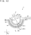
- the laser oscillator 11 is provided with, for example, an optical device 100 and a laser device 200, as shown in Fig. 12 .
- the laser device 200 is provided around the optical device 100 and is configured to irradiate seed light 500 to an input surface 101 of the optical device 100 from a plurality of directions.
- the optical device 100 is configured to irradiate the seed light 500, that is irradiated to the input surface 101, as the output laser light 501 from an output surface 102.
- a direction in which the output laser light 501 is irradiated is determined based on wavelength and irradiation direction of the seed light 500 that the laser device 200 irradiates to the optical device 100.
- the wavelength and the irradiation direction of the seed light 500 are configured so as to be controlled by the controller 30.
- the seed light 500 is a generic term of first seed light 500-1 (not illustrated), second seed light 500-2 (not illustrated), ..., and N-th seed light 500-N (not illustrated) of which irradiation directions are different.
- the output laser light 501 is a generic term of first output laser light 501-1 (not illustrated), second output laser light 501-2 (not illustrated), .., and N-th output laser light 501-N that are irradiated when each of the seed light 500 is irradiated to the optical device 100.
- the optical device 100 irradiates the first output laser light 501-1.
- the optical device 100 When the second seed light 500-2 is irradiated to the optical device 100, the optical device 100 irradiates the second output laser light 501-2. When the N-th seed light 500-N is irradiated to the optical device 100, the optical device 100 irradiates the N-th output laser light 501-N.
- the optical device 100 is formed in a cylindric shape, for example, and has an input surface 101 and an output surface 102 in one bottom surface.
- the input surface 101 is a plane surface provided at an edge portion of this bottom surface for example, and is configured so as to be irradiated by the laser device 200 with the seed light 500.
- the output surface 102 is a plane surface provided to this bottom surface and is configured to irradiate the output laser light 501.
- the output surface 102 may be formed in a circular shape in a center of this bottom surface, for example.
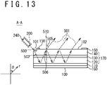
- the optical device 100 is formed with a second reflection mirror 120, an active layer 130, a first reflection mirror 140 and a first electrode 150 that are laminated on one surface of a substrate 110 in order. Boundaries between each layer are provided in parallel to a bottom surface of the optical device 100 for example, the output surface 102 for example. In addition, a second electrode 160 is provided adjacent to another surface of the substrate 110.
- the first reflection mirror 140 has an input surface 101 at an end portion of a surface thereof, for example.
- the seed light 500 irradiated from the laser device 200 is incident from the input surface 101 to the first reflection mirror 140.
- the input surface 101 is configured so that a reflectance thereof is lower compared to another portion of the surface of the first reflection mirror 140.
- the first reflection mirror 140 is formed so that a thickness of the first reflection mirror 140 at a position where the input surface 101 is provided is thinner than a thickness of the first reflection mirror 140 at another position.
- the input surface 101 is, for example, a plane surface parallel to the output surface 102.
- the propagation laser light 502 is a generic term of first propagation laser light 502-1, second propagation laser light 502-2, .., and N-th propagation laser light 502-N which propagate in the optical device 100 when each of the seed light 500 is irradiated.
- first propagation laser light 502-1 when the first seed light 500-1 is irradiated to the optical device 100, it travels in the optical device 100 as the first propagation laser light 502-1.
- the second seed light 500-2 When the second seed light 500-2 is irradiated to the optical device 100, it travels in the optical device 100 as the second propagation laser light 502-2.
- the N-th seed light 500-N is irradiated to the optical device 100, it travels in the optical device 100 as the N-th propagation laser light 502-N.
- the first reflection mirror 140 and the second reflection mirror 120 are provided to face to each other and form a planar waveguide 170 between the first reflection mirror 140 and the second reflection mirror 120.
- the second reflection mirror 120 reflects the propagation laser light 502 incident from the input surface 101. A portion of the propagation laser light 502 reflected by the second reflection mirror 120 is reflected to the first reflection mirror 140.
- the propagation laser light 502 reflected by the first reflection mirror 140 is reflected by the second reflection mirror 120.
- the propagation laser light 502 is reflected by the first reflection mirror 140 and the second reflection mirror 120 in order to travel in the planar waveguide 170.
- the first reflection mirror 140 and the second reflection mirror 120 are formed so as to carry out Bragg reflection and include a Distributed Bragg Reflector for example.
- the first reflection mirror 140 transmits a portion of the propagation laser light 502 and reflects another portion thereof.
- the propagation laser light 502 reflected by the first reflection mirror 140 travels inside the optical device 100.
- the propagation laser light 502 transmitted through the first reflection mirror 140 is irradiated from the output surface 102 formed on the surface of the first reflection mirror 140 as the output laser light 501.
- the second reflection mirror 120 may reflect the whole propagation laser light 502.
- the reflectance of the first reflection mirror 140 may be configured to be lower than the reflectance of the second reflection mirror 120.
- the thickness of the first reflection mirror 140 may be thinner than the thickness of the second reflection mirror 120.
- the active layer 130 is provided between the first reflection mirror 140 and the second reflection mirror 120 and amplifies the propagation laser light 502 passing through the active layer 130.
- the propagation laser light 502 travels in the planar waveguide 170, a portion of the propagation laser light 502 is irradiated as the output laser light 501 and another portion of the propagation laser light 502 is amplified by the active layer 130.
- the active layer 130 is excited by a current that flows between the first electrode 150 and the second electrode 160.
- the active layer 130 may be excited until it becomes a luminescent state.
- the first electrode 150 and the second electrode 160 are provided to sandwich the active layer 130.
- the first electrode 150 and the second electrode 160 are connected to the controller 30.
- the controller 30 draws a current between the first electrode 150 and the second electrode 160 and excites the active layer 130.
- the controller 30 adjusts the amplification of the propagation laser light 502 by the active layer 130, by controlling the current which flows in the active layer 130.
- the first electrode 150 is formed so as not to overlap the input surface 101 irradiated with the seed light 500 and the output surface 102 irradiated with the output laser light 501.
- the input surface 101 is provided at an edge portion of the optical device 100 in a direction in which the seed light 500 is irradiated.
- the output surface 102 is formed, for example, in a circular shape in a center of the bottom surface of the optical device 100.
- the optical device 100 propagates the propagation laser light 502 along the planar waveguide 170 provided between the first reflection mirror 140 and the second reflection mirror 120, and irradiates the output laser light 501 from the output surface 102.
- the optical device 100 includes a Vertical Cavity Surface Emitting LASER (VCSEL) for example.
- VCSEL Vertical Cavity Surface Emitting LASER
- a diameter of the output surface 102 of the optical device 100 may be 1 cm.
- the laser device 200 is provided with a plurality of seed light sources 240 (a first seed light source 240-1, a second seed light source 240-2, ..., a N-th seed light source 240-N), for example.
- the seed light sources 240 irradiate the seed light 500 to the optical device 100.
- each of the seed light sources 240 with different direction of irradiating the seed light 500, irradiates the first seed light 500-1, the second seed light 500-2, ..., and the N-th seed light 500-N.
- the first seed light source 240-1 irradiates the first seed light 500-1 to the optical device 100.
- the second seed light source 240-2 irradiates the second seed light 500-2 to the optical device 100.
- the N-th seed light source 240-N irradiates the N-th seed light 500-N to the optical device 100.
- the seed light source 240 may be connected to a device that outputs the seed light 500 via an optical switch and may be configured to irradiate the seed light 500 outputted by this device.
- the optical switch selects a seed light source 240 that irradiates the seed light 500.
- An example of the seed light source 240 includes a collimator, a fiber array that bundles optical fibers, and the like.
- the seed light sources 240 are arranged to surround the optical device 100.
- the seed light sources 240 are arranged to surround a half of the optical device 100 when viewed from a normal direction of the output surface 102 for example, and each of the seed light sources 240 is arranged at equal intervals.
- a spherical coordinate system with a center of the output surface 102 as its origin.
- a distance from the origin will be referred to as a radius r
- an angle from a normal line 510 of the output surface 102 will be referred to as a polar angle ⁇
- a direction in a planar direction of the output surface 102 when viewed from the origin will be referred to as an azimuthal ⁇ .
- the laser device 200 irradiates the seed light 500 to the optical device 100 from an i-th seed light source 240-i and a k-th seed light source 240-k, for example.
- Azimuthal ⁇ of the irradiation direction of the seed light 500 that the i-th seed light source 240-i and the k-th seed light source 240-k irradiate is not parallel to each other.
- the azimuthal ⁇ of the traveling direction of the i-th propagation laser light 502-i corresponding to the i-th seed light 500-i and the azimuthal ⁇ of the traveling direction of the k-th propagation laser light 502-k corresponding to the k-th seed light 500-k are not parallel to each other.
- the azimuthal ⁇ of the irradiation direction of the i-th output laser light 501-i corresponding to the i-th propagation laser light 502-i and the azimuthal ⁇ of the irradiation direction of the k-th output laser light 501-k corresponding to the k-th propagation laser light 502-k are not parallel to each other.
- the azimuthal ⁇ of the irradiation direction of the output laser light 501 when the seed light 500 is irradiated from the i-th seed light source 240-i and the azimuthal ⁇ of the irradiation direction of the output laser light 501 when the seed light 500 is irradiated from the k-th seed light source 240-k are different.
- the azimuthal ⁇ of the irradiation direction of the output laser light 501 can be changed by changing the seed light source 240 that is to irradiate the seed light 500.
- the laser oscillators 11 can control the azimuthal ⁇ of the irradiation direction of the output laser light 501 by changing the seed light source 240 that irradiates the seed light 500.
- the azimuthal ⁇ of the irradiation direction of the output laser light 501 can be controlled by irradiation by the laser device 200 of a plurality of beams of seed light 500 of which the azimuthal ⁇ of the traveling direction is not parallel to each other in the planar waveguide 170.
- a plurality of optical paths of the propagation laser light 502, that is irradiated from a plurality of seed light sources 240 and travels inside the optical device 100, may cross each other inside the planar waveguide 170 formed in the optical device 100, when viewed from the normal direction of the output surface.
- an optical path of the i-th propagation laser light 502-i and an optical path of the k-th propagation laser light 502-k may cross inside the planar waveguide 170 when viewed from the normal direction of the output surface.
- two seed light sources 240 of the plurality of seed light sources 240 may irradiate seed light 500 to the optical device 100 from parallel directions.
- the polar angle ⁇ of the irradiation direction of the output laser light 501 can be changed by changing a wavelength of the seed light 500 irradiated from the seed light source 240.
- the seed light 500 is irradiated to the input surface 101 from a direction inclined with respect to the normal direction of the input surface 101 and is guided inside the optical device 100 as the propagation laser light 502.
- the propagation laser light 502 is reflected by the first reflection mirror 140 and the second reflection mirror 120.
- ⁇ i an incident angle 506 of the propagation laser light 502 at the first reflection mirror 140
- the following equation (1) holds based on Bragg's law.
- [Math Equation 1] sin ⁇ i 1 ⁇ ⁇ ⁇ c 2
- the incident angle 506 indicates an angle between an incident direction of the propagation laser light 502 with respect to the first reflection mirror 140 and the normal line 510 of the output surface 102.
- ⁇ indicates a wavelength of the propagation laser light 502
- ⁇ c indicates a cut-off wavelength of the planar waveguide 170.
- the first reflection mirror 140 transmits a portion of the propagation laser light 502, which is incident with an incident angle 506, as the output laser light 501.
- the output laser light 501 is refracted at the output surface 102, which is provided to the first reflection mirror 140, and is irradiated.
- the wavelength of the output laser light 501 is equal to the wavelength of the propagation laser light 502
- an output angle 505 which indicates an angle between a direction in which the output laser light 501 is irradiated and the normal line 510 of the output surface 102 is referred to as ⁇ 0
- the following equation (2) holds.
- n air indicates a refraction index of the atmosphere
- n wg indicates a refraction index of the planar waveguide 170.
- the output angle 505 varies based on the wavelength of the seed light 500.
- the output angle 505 indicates a polar angle ⁇ of the direction in which the output laser light 501 is irradiated
- the polar angle ⁇ of the direction in which the output laser light 501 is irradiated is changed based on the wavelength of the seed light 500.
- the laser oscillator 11 can control the polar angle ⁇ of the irradiation direction of the output laser light 501 by changing the wavelength of the seed light 500.
- the laser oscillator 11 can change non-mechanically and two-dimensionally the direction of the output laser light 501 to irradiate by controlling the seed light source 240 that irradiates the seed light 500 and the wavelength of the laser light that the seed light source 240 irradiates.
- the laser oscillator 11 can change a polar angle and an azimuthal of the direction to irradiate laser light in a spherical coordinate system with a position of outputting the laser light as an origin and a direction of irradiating the laser light as a zenith.
- the controller 30 can control the irradiation direction of the output laser light 501 by selecting the wavelength of the seed light 500 and the seed light source 240. Output energy of the output laser light 501 is adjusted by a control of the controller 30 on a current which flows between the first electrode 150 and the second electrode 160, and output energy of the seed light 500.
- a direction in which each of the laser oscillators 11 can irradiate output laser light 501 may not be identic.
- directions in which adjacent laser oscillators 11 can irradiate output laser light 501 may be different.
- irradiation directions can be completed.
- directions in which the laser array 10 can irradiate output laser light 501 can be widened.
Landscapes
- Physics & Mathematics (AREA)
- Engineering & Computer Science (AREA)
- Electromagnetism (AREA)
- General Physics & Mathematics (AREA)
- Remote Sensing (AREA)
- Radar, Positioning & Navigation (AREA)
- Computer Networks & Wireless Communication (AREA)
- Optics & Photonics (AREA)
- Condensed Matter Physics & Semiconductors (AREA)
- General Engineering & Computer Science (AREA)
- Lasers (AREA)
- Optical Radar Systems And Details Thereof (AREA)
- Control Of Indicators Other Than Cathode Ray Tubes (AREA)
- Length Measuring Devices By Optical Means (AREA)
Abstract
Description
- The present invention relates to a laser irradiation apparatus and a storage medium that stores a laser irradiation program.
- Technologies of irradiating a target with high-power laser light to remotely destroying the target are researched. For example,
Patent Literature 1 discloses a technology of irradiating high-power continuous wave laser light to destroy a target. An apparatus described in thePatent Literature 1 converts high-power continuous wave laser light to pulse laser light by pulse converter and irradiates the converted laser light to the target. An optical sensor receives reflected light of this laser light and detects the target. A controller stops pulse conversion process of the pulse converter so that continuous wave laser light is irradiated to the target and the target is destroyed. - In addition, a technology of changing irradiation direction of laser light non-mechanically is researched. For example,
Patent Literature 2 discloses a technology of changing laser irradiation direction by wavelength. An apparatus described in thePatent Literature 2 is provided with a waveguide having two distributed Bragg reflection mirrors, a light incident port for incident light in the waveguide and a light emission port for emitting light that is guided in the waveguide. -
Patent Literature 3 discloses a technology of changing irradiation direction of high-power laser non-mechanically. The apparatus disclosed in thePatent Literature 3 is provided with a first vertical cavity surface emitting laser (VCSEL) long in a first direction and a driving circuit that injects current to the first VCSEL. Incident light, that incidents in the incident port provided at an end in the first direction of the first VCSEL, travels inside the first VCSEL along the first direction, while being reflected in a vertical direction, and is emitted from the emitting port on an upper surface of the first VCSEL as emission light. It is disclosed that a direction in which this emission light is emitted is inclined to the first direction from a normal direction of the emitting port based on a wavelength of the incident light and the like. -
- [Patent Literature 1]
Japanese Patent Publication No. 2010-127818 A - [Patent Literature 2]
Japanese Patent Publication No. 2013-16591 A - [Patent Literature 3]
Japanese Patent Publication No. 2017-157609 A - The present invention has been made in view of the above circumstances and one objective thereof is to provide a laser irradiation apparatus that efficiently carries out processes such as detection of target by use of laser light. Other objectives will be understood from following disclosures and explanations of embodiments.
- The laser irradiation apparatus according to an embodiment to achieve the above objective is provided with a laser array, a detector and a controller. The laser array is provided with a plurality of laser oscillators including a first laser oscillator that irradiates first detection laser light and a second laser oscillator that irradiates second dealing laser light. The detector obtains detection information based on reflected light that is the first detection laser light reflected by a target. The controller estimates a position of the target based on the detection information and generate a second dealing signal that instructs the second laser oscillator to irradiate the second dealing laser light to the estimated position of the target. The second laser oscillator irradiates the second dealing laser light to the estimated position of the target based on the second dealing signal.
- The laser irradiation apparatus according to an embodiment is provided with a laser array with a plurality of laser oscillators arranged in an array. The plurality of laser oscillators is provided with a first laser oscillator group including a part of laser oscillators of the plurality of laser oscillators and a second laser oscillator group including a part of laser oscillators of the plurality of laser oscillators. The first laser oscillator group irradiates a first laser light group in a first direction to display a first image in the first direction. The second laser oscillator group irradiates a second laser light group in a second direction different from the first direction to display a second image in the second direction.
- A storage medium that stores a laser irradiation program according to an embodiment is a non-transitory storage medium that stores a program which controls a first laser oscillator and a second laser oscillator arranged in a laser array , the program including a step of generating a detection signal that instructs the first laser oscillator to irradiate detection laser light and a step of generating, based on detection information obtained by receiving reflected light that is the detection laser light reflected by a target, a dealing signal that instructs the second laser oscillator to irradiate dealing laser light to the target.
- According to the present invention, a process such as detection of a target is efficiently carried out.
-
- [
Fig. 1] Fig. 1 is a schematic diagram of a laser irradiation apparatus according to an embodiment. - [
Fig. 2] Fig. 2 is a flowchart related to an operation of a laser irradiation apparatus according to an embodiment. - [
Fig. 3] Fig. 3 is a diagram to describe a detection space of a laser irradiation apparatus according to an embodiment. - [
Fig. 4] Fig. 4 is a diagram to describe a process of estimating a position of a target according to an embodiment. - [
Fig. 5] Fig. 5 is a diagram to describe an operation of dealing a plurality of targets according to an embodiment. - [
Fig. 6] Fig. 6 is a diagram to describe an operation of dealing a moving target according to an embodiment. - [
Fig. 7] Fig. 7 is an enlarged view of a laser array to describe an operation of dealing a moving target according to an embodiment. - [
Fig. 8] Fig. 8 is a diagram to describe an operation of dealing a moving target according to an embodiment. - [
Fig. 9] Fig. 9 is a diagram to describe an operation of displaying an image on a laser array according to an embodiment. - [
Fig. 10] Fig. 10 is a diagram to describe an operation of a laser array that displays different images depending on viewing direction according to an embodiment. - [
Fig. 11] Fig. 11 is a schematic diagram of a controller according to an embodiment. - [
Fig. 12] Fig. 12 is a schematic diagram of a laser oscillator according to an embodiment. - [
Fig. 13] Fig. 13 is an A-A cross-sectional view inFig. 12 . - A
laser irradiation apparatus 1 according to an embodiment is configured to detect atarget 2 by use ofoutput laser light 501 and destroy thetarget 2. As shown inFig. 1 , thelaser irradiation apparatus 1 is provided with alaser array 10, adetector 20 and acontroller 30. - The
laser array 10 is formed with a plurality oflaser oscillators 11 that irradiateoutput laser light 501 and are arranged in an array on a surface thereof. For example, thelaser oscillators 11 may be regularly arranged, in a grid pattern for example. Thelaser oscillator 11 may be arranged irregularly. Thelaser oscillators 11 are arranged in thelaser array 10 at a high density: for example, 400 ormore laser oscillators 11 are arranged per square meter. Thelaser oscillators 11 may be arranged at a density of ten thousand or more per square. - The
laser oscillators 11 can arbitrarily change a direction of irradiating theoutput laser light 501. For example, thelaser oscillator 11 change the direction of irradiating theoutput laser light 501 non-mechanically and two-dimensionally. When atarget 2 such as a drone exists on an optical axis of theoutput laser light 501 irradiated by thelaser oscillator 11, thetarget 2 reflects theoutput laser light 501 as reflectedlight 503. Detail of thelaser oscillator 11 will be described later. - The
detector 20 receives thereflected light 503 reflected by thetarget 2 and obtains detection information such as an image in which thetarget 2 is taken. For example, thedetector 20 includes an optical camera such as a visible ray camera, an infrared ray camera and an ultraviolet ray camera, and takes an image of thetarget 2 irradiated by theoutput laser light 501. Thedetector 20 obtains an image in which thetarget 2 is taken as detection information and transmits it to thecontroller 30. Thedetector 20 may select an arbitrary device to detect thereflected light 503. - The
controller 30 estimates a position of thetarget 2 based on the detection information such as the image obtained by thedetector 20. Thecontroller 30 extracts a location in the image taken by thedetector 20 where thetarget 2 is shown. Thecontroller 30 estimates the position of thetarget 2 based on the direction in which thedetector 20 has taken the image and the location where thetarget 2 is shown in the image that has been taken. Thecontroller 30 transmits to the plurality oflaser oscillators 11 a request to irradiate theoutput laser light 501 to the estimated position of thetarget 2. - The plurality of
laser oscillators 11 irradiate theoutput laser light 501 to the estimated positions of thetarget 2. For example, all of thelaser oscillators 11 that can irradiate to the position of thetarget 2 may irradiate theoutput laser light 501 to the position of thetarget 2. At the position of thetarget 2, energy of theoutput laser light 501 is increased by overlaying theoutput laser light 501 irradiated by the plurality oflaser oscillators 11. As a result, thelaser irradiation apparatus 1 can destroy thetarget 2. For this reason, theoutput laser light 501 irradiated by thelaser oscillators 11 may have phases that interfere so that energies of theoutput laser light 501 strengthen each other at the position of thetarget 2. In this case, the phase of theoutput laser light 501 irradiated by eachlaser oscillator 11 is instructed by thecontroller 30. - As described above, the
laser irradiation apparatus 1 can irradiateoutput laser light 501 as detection laser light to detect atarget 2 and irradiate to the target 2 a plurality of beams of theoutput laser light 501 as dealing laser light to attack the detectedtarget 2. For this reason, detection of thetarget 2 and attack on thetarget 2 can be efficiently performed. It should be noted that thelaser array 10 may be provided with alaser oscillator 11 that can irradiate only detection laser light. In addition, thelaser array 10 may be provided with alaser oscillator 11 that can irradiate only dealing laser light. Alllaser oscillators 11 included in thelaser array 10 may be configured to be able to irradiate detection laser light and dealing laser light. - An operation of the
laser irradiation apparatus 1 will be described in more detail. Thelaser irradiation apparatus 1 carries out processes shown inFig. 2 . In step S100, thedetector 20 starts a monitoring such as taking images for detecting thetarget 2 and obtains detection information. A direction in which thedetector 20 detects, for example a direction of taking image, may be determined based on an instruction from thecontroller 30. The direction in which thedetector 20 detects may be fixed to a predetermined direction. - In step S110, a
laser oscillator 11 irradiatesoutput laser light 501 as detection laser light. Thecontroller 30 determines thelaser oscillator 11 which irradiates the detection laser light and generates a detection signal which indicates to thedetermined laser oscillator 11 to irradiate the detection laser light. As thelaser oscillator 11 that is to irradiate the detection laser light, one of thelaser oscillators 11 that can irradiate detection laser light to a detection space 600 to be detected may be selectively determined. For example, as shown inFig. 3 , thecontroller 30 transmits a detection signal to a first laser oscillator 11-1 and a second laser oscillator 11-2 of the plurality oflaser oscillators 11. A direction of irradiating the detection laser light is indicated in the detection signal. The first laser oscillator 11-1 irradiates detection laser light to a first detection space 600-1 based on the received detection signal. The second laser oscillator 11-2 irradiates detection laser light to a second detection space 600-2 based on the received detection signal. For example, the first detection space 600-1 and the second detection space 600-2 are different spaces. The first detection space 600-1 and the second detection space 600-2 may be overlapped or not overlapped. Alllaser oscillators 11 provided to thelaser array 10 may irradiate detection laser light or a part of thelaser oscillators 11 may irradiate detection laser light. Asingle laser oscillator 11 may irradiate detection laser light. - In step S120, the
controller 30 determines whether information of thetarget 2 is included in the detection information obtained by thedetector 20. For example, thecontroller 30 determines that information of thetarget 2 is included when there is in an image taken by thedetector 20 an area brighter than a predetermined threshold value. When it is determined that the information of thetarget 2 is included in the detection information, the process proceeds to step S130. When it is determined that the information of thetarget 2 is not included in the detection information, the process returns to step S110 and the process is repeated until thetarget 2 is detected. - In step S130, the
controller 30 estimates a position of thetarget 2 based on the detection information. For example, when thelaser irradiation apparatus 1 is provided with a plurality ofdetectors 20, thecontroller 30 extracts the location in which thetarget 2 is shown from the image taken by each of thedetectors 20. Atarget direction 601 from thedetector 20 toward thetarget 2 is estimated based on the extracted position of thetarget 2 and the direction in which thedetector 20 takes image. As shown inFig. 4 , thecontroller 30 estimates a location in which a straight line elongated along thetarget direction 601 from eachdetector 20 toward thetarget 2 crosses as the position of thetarget 2. - For example, when the
laser oscillator 11 irradiates pulse laser light as detection laser light, thecontroller 30 estimates a distance from thedetector 20 to thetarget 2 based on a time from when thelaser oscillator 11 irradiates the detection laser light to when thedetector 20 receives reflectedlight 503. Thetarget direction 601 from thedetector 20 toward thetarget 2 is estimated based on the detection information obtained by thedetector 20. Thecontroller 30 estimates the position of thetarget 2 based on the distance from thedetector 20 to thetarget 2 and thetarget direction 601. - In step S140, the
controller 30 controls thelaser oscillator 11 and irradiatesoutput laser light 501 as dealing laser light to thetarget 2. Thecontroller 30 determines a plurality oflaser oscillators 11 that irradiate dealing laser light and transmits dealing signal for irradiating dealing laser light to the position of thetarget 2 estimated in step S130 to the determined plurality oflaser oscillators 11. Thelaser oscillators 11 are specified by the dealing signal in the direction of irradiating the dealing laser light and irradiate the dealing laser light in the specified direction. The dealing laser light irradiated by thelaser oscillators 11 is overlayed on thetarget 2 and destroys thetarget 2. - The
laser oscillator 11 that irradiates the dealing laser light is determined based on the position of thetarget 2. Alaser oscillator 11 of thelaser oscillators 11, that can irradiate dealing laser light to thetarget 2, irradiates the dealing laser light to thetarget 2. For example, all of thoselaser oscillators 11 may irradiate the dealing laser light to thetarget 2. In addition, a part of thoselaser oscillators 11, forexample laser oscillators 11 of which irradiation angle is equal to or less than 30 degrees, may irradiate the dealing laser light to thetarget 2. The irradiation angle indicates an angle between a direction from alaser oscillator 11 toward a center of a space to which thelaser oscillator 11 can irradiateoutput laser light 501 and an irradiation direction of theoutput laser light 501. It should be noted that alaser oscillator 11 that does not irradiate dealing laser light may irradiate detection laser light as an operation in step S110. The space to which the detection laser light is irradiated may be overlayed to a space in which thelaser oscillator 11, that is irradiating dealing laser light, was irradiating detecting laser light. In addition, the space to which this detection laser light is irradiated may include the space in which thelaser oscillator 11, that is irradiating dealing laser light, was irradiating detection laser light. - The
laser oscillator 11 changes a location to irradiate dealing laser light in accordance with a movement of thetarget 2. Thedetector 20 obtains detection information while thelaser oscillator 11 is irradiating dealing laser light. Since thetarget 2 reflects the dealing laser light as reflected light 503, information of thetarget 2 is included in the detection information. Thecontroller 30 estimates the position of thetarget 2 based on this detection information, similarly to step S130. Dealing signal with updated position of thetarget 2 is transmitted to thelaser oscillator 11 that is already determined. Thelaser oscillator 11 irradiates dealing laser light to the updated position of thetarget 2. The position of thetarget 2 may be estimated by irradiating detection laser light to thetarget 2 from alaser oscillator 11 that has not irradiated dealing laser light. - In step S150, the
controller 30 determines whether thetarget 2 is destroyed. Thecontroller 30 verifies whether thetarget 2 exists at the estimated position of thetarget 2, based on detection information obtained by thedetector 20. For example, thecontroller 30 determines whether information of thetarget 2 is included in the detection information, similarly to step S120. When no information of thetarget 2 is included in the detection information, thecontroller 30 determines that thetarget 2 is destroyed. When information of thetarget 2 is included in the detection information, the position of thetarget 2 is estimated, similarly to step S130. When the location to which thelaser oscillator 11 is irradiating dealing laser light, is not included in the estimated position of thetarget 2, thecontroller 30 determines that thetarget 2 is destroyed. When the estimated position of thetarget 2 is same as the location to which thelaser oscillator 11 is irradiating dealing laser light, thecontroller 30 determines that thetarget 2 is not destroyed. When thecontroller 30 determines that thetarget 2 is not destroyed, the process returns to step S140 and thelaser oscillator 11 continues irradiating the dealing laser light to thetarget 2. When thecontroller 30 determines that thetarget 2 is destroyed, the process returns to step S110 and thelaser oscillator 11 irradiates detection laser light. - As described above, the
laser irradiation apparatus 1 performs detection and destruction oftarget 2 by irradiating detection laser light and dealing laser light fromlaser oscillators 11. Energy of the detection laser light may be smaller than energy of the dealing laser light. - As shown in
Fig. 5 , thelaser irradiation apparatus 1 may irradiate dealing laser light to a plurality oftargets 2. For example, information of a first target 2-1 and a second target 2-2 is included in the detection information that thedetector 20 obtains. Thecontroller 30 estimates a position of the first target 2-1 and a position of the second target 2-2, based on the detection information. Thecontroller 30 determines alaser oscillator 11 that irradiates dealing laser light to the first target 2-1 based on the estimated position of the first target 2-1 and determines alaser oscillator 11 that irradiates dealing laser light to the second target 2-2 based on the estimated position of the second target 2-2. When a first laser oscillator 11-1 that can irradiate dealing laser light to the first target 2-1 is different from a second laser oscillator 11-2 that can irradiate dealing laser light to the second target 2-2, thecontroller 30 transmits a dealing signal for irradiating dealing laser light to thetargets 2 to eachlaser oscillator 11. Thelaser oscillators 11 irradiate dealing laser light to the first target 2-1 or the second target 2-2, based on the dealing signal. - When there is a
laser oscillator 11 that can irradiate dealing laser light to both of the first target 2-1 and the second target 2-2, thecontroller 30 determines atarget 2 to assign to thislaser oscillator 11. For example, thecontroller 30 may assign atarget 2 of which irradiation angle becomes smallest to thelaser oscillator 11. Atarget 2 may be assigned to thelaser oscillator 11 so that a number oflaser oscillators 11 that irradiates dealing laser light to the first target 2-1 becomes equal to a number oflaser oscillators 11 that irradiates dealing laser light to the second target 2-2. - The
controller 30 may estimate target information such as a position, a speed, an acceleration and a traveling direction of thetarget 2 based on the detection information that thedetector 20 has obtained, and may determine thetarget 2 to assign to thelaser oscillator 11. For example, thecontroller 30 may assign atarget 2 of which a distance from thelaser irradiation apparatus 1 is the shortest to thelaser oscillator 11. Based on a position and a speed of thetarget 2, atarget 2 that reaches thelaser irradiation apparatus 1 the fastest may be assigned to thelaser oscillator 11. To estimate a speed or the like of thetarget 2, at first, thecontroller 30 estimates a position of thetarget 2 at each time based on detection information that thedetector 20 has obtained at different times. Next, thecontroller 30 estimates the speed or the like of thetarget 2 based on the times at which thedetector 20 has obtained the detection information and a position of thetarget 2 at each time. When thelaser irradiation apparatus 1 protects facilities or the like, thecontroller 30 may assign atarget 2 of which a distance from the facilities to protect is the closest to thelaser oscillator 11. Thetarget 2 that reaches the facilities to protect the fastest may be assigned to thelaser oscillator 11. - The target information may include types of moving objects such as aircraft, drone, flying object and vehicle. The
controller 30 may estimate a type of thetarget 2 such as aircraft, drone, flying object and vehicle based on the detection information that thedetector 20 has obtained and may determine thetarget 2 to assign to thelaser oscillator 11. In this case, thecontroller 30 estimates a shape of thetarget 2 based on the detection information that thedetector 20 has obtained. Thecontroller 30 searches for a registered shape that is the closest to the estimated shape in registered shapes that are registered. The type that corresponds to the registered shape that is searched is estimated as the type of thetarget 2. A priority that corresponds to the estimated type is searched and atarget 2 of which the priority is the highest is assigned to thelaser oscillator 11. In this case, registered shapes, types and priorities are registered in association in thecontroller 30. In addition, a use, a model and the like of moving objects may be included in the target information. In this case, the priority is set to the use, the model and the like of the moving objects. - The
controller 30 may calculate a threat level of thetarget 2 based on the detection information that thedetector 20 has obtained and may assign atarget 2 of which the threat level is the highest to thelaser oscillator 11. The threat level is calculated based on a type, a size, a speed, a traveling direction and the like of thetarget 2. - The
controller 30 may be provided with an input device and may assign atarget 2 selected by a user to thelaser oscillator 11. - As shown in
Fig. 6 , when thetarget 2 moves with a speed including a directional component parallel to an in-plane direction of the surface of thelaser array 10, thecontroller 30 may change alaser oscillator 11 that irradiates dealing laser light in accordance with the movement of thetarget 2. For ease of understanding, it will be described by use of a cartesian coordinate system. It will be described with x direction and y direction as in-plane directions of the surface of thelaser array 10 and z direction as normal direction of the surface of thelaser array 10. - For example, when the
target 2 moves in +x direction, thecontroller 30 assigns thetarget 2 to the second laser oscillator 11-2 that is arranged in +x direction from the first laser oscillator 11-1 that is irradiating dealing laser light to thetarget 2. Thecontroller 30 stops the irradiation of the dealing laser light by the first laser oscillator 11-1. When thetarget 2 further moves in +x direction, thecontroller 30 assigns thetarget 2 to the third laser oscillator 11-3 that is arranged in +x direction from the second laser oscillator 11-2 that is irradiating dealing laser light to thetarget 2. Thecontroller 30 stops the irradiation of the dealing laser light by the second laser oscillator 11-2. - In particular, when the
target 2 moves in +x direction, thelaser oscillators 11 operate as following. As shown inFig. 7 ,irradiation oscillators 11a of thelaser oscillators 11 are irradiating dealing laser light to thetarget 2.Adjacent oscillators 11b of thelaser oscillators 11, that are arranged in anadjacent area 12 that is adjacent to theirradiation oscillators 11a, are not irradiating dealing laser light. - When the
target 2 moves in +x direction, a part of theadjacent oscillators 11b irradiates dealing laser light to thetarget 2. As thetarget 2 moves in +x direction, a firstadjacent oscillator 11b-1 arranged in +x direction from theirradiation oscillators 11a can irradiate dealing laser light to thetarget 2 with an angle with which theirradiation oscillators 11a were irradiating. As a result, thecontroller 30 generates dealing signal so that the firstadjacent oscillator 11b-1 irradiates dealing laser light to thetarget 2. The firstadjacent oscillator 11b-1 irradiates dealing laser light to thetarget 2 based on the dealing signal. - When the
target 2 moves in +x direction, a part of theirradiation oscillators 11a stops the irradiation of the dealing laser light. As thetarget 2 moves in +x direction, afirst irradiation oscillator 11a-1, which is arranged in -x direction that is a direction opposite to the movement direction of thetarget 2, cannot irradiate dealing laser light to thetarget 2 with the angle with which theirradiation oscillators 11a were irradiating. For this reason, thecontroller 30 generates dealing signal for thefirst irradiation oscillator 11a-1 so as to stop the irradiation of the dealing laser light. Thefirst irradiation oscillator 11a-1 stops the irradiation of the dealing laser light based on the dealing signal. - The first
adjacent oscillator 11b-1 may irradiate dealing laser light before thefirst irradiation oscillator 11a-1 stops the irradiation of the dealing laser light. In addition, the firstadjacent oscillator 11b-1 may irradiate dealing laser light after thefirst irradiation oscillator 11a-1 stopped the irradiation of the dealing laser light. The firstadjacent oscillator 11b-1 may irradiate dealing laser light at a same time as thefirst irradiation oscillator 11a-1 stops the irradiation of the dealing laser light. - The
controller 30 may generate a dealing signal to transmit to the firstadjacent oscillator 11b-1 before generating a dealing signal to transmit to thefirst irradiation oscillator 11a-1. In addition, thecontroller 30 may generate a dealing signal to transmit to the firstadjacent oscillator 11b-1 after generating a dealing signal to transmit to thefirst irradiation oscillator 11a-1. Thecontroller 30 may generate a dealing signal to transmit to the firstadjacent oscillator 11b-1 at a same time as generating a dealing signal to transmit to thefirst irradiation oscillator 11a-1. - An
adjacent oscillator 11b arranged in theadjacent area 12 may be controlled so as not to irradiate detection laser light. It can be said that anadjacent oscillator 11b is alaser oscillator 11 with high probability of irradiating dealing laser light to thetarget 2. An irradiation direction of detection laser light is controlled so that detection laser light is irradiated to entire detection space 600. By controlling anadjacent oscillator 11b not to irradiate detection laser light, it is suppressed from starting irradiation of dealing laser light while irradiating detection laser light to the detection space 600. A shape of theadjacent area 12 may be changed in accordance with a traveling direction, a speed, an acceleration or the like of thetarget 2. - The
controller 30 can control thelaser oscillator 11 in a case in which thetarget 2 moves in y direction or the like, as in the case of movement in x direction. - As shown in
Fig. 8 , thecontroller 30 may estimate anestimation path 3 of thetarget 2 based on the detection information and may determine alaser oscillator 11 that irradiates dealing laser light to thetarget 2 based on theestimation path 3.Laser oscillators 11 that are irradiating dealing laser light to thetarget 2 are arranged in anirradiation area 13. In this case, at first, thecontroller 30 estimates theestimation path 3 of thetarget 2. For example, target information such as a position, a speed, an acceleration and a model of thetarget 2 is estimated based on the detection information that thedetector 20 has obtained. Theestimation path 3 of thetarget 2 is estimated based on the estimated target information of thetarget 2. - Next, the
controller 30 determines alaser oscillator 11 that irradiates dealing laser light to thetarget 2 at desired times, based on theestimation path 3. For example, thecontroller 30 estimates estimation positions 4 of thetarget 2 at the desired times, such as a first estimation position 4-1 and a second estimation position 4-2, based on theestimation path 3 of thetarget 2. Alaser oscillator 11 that irradiates dealing laser light when thetarget 2 reaches the first estimation position 4-1 (for example, alaser oscillator 11 arranged in a first estimation irradiation area 14-1) is determined based on the first estimation position 4-1. Similarly, alaser oscillator 11 that irradiates dealing laser light when thetarget 2 reaches the second estimation position 4-2 (for example, alaser oscillator 11 arranged in a second estimation irradiation area 14-2) is determined based on the second estimation position 4-2. - The
controller 30 determines a schedule for thelaser oscillator 11 to irradiate dealing laser light to thetarget 2 and controls thelaser oscillator 11 based on the schedule. Thecontroller 30 determines a schedule for eachlaser oscillator 11 to irradiate dealing laser light, based on times when thetarget 2 reaches the estimation positions 4 and thelaser oscillators 11 arranged in the estimation irradiation areas 14. Thecontroller 30 generates dealing signal to control thelaser oscillators 11, according to this schedule. For example, the dealing signal is transmitted to thelaser oscillators 11 arranged in the first estimation irradiation area 14-1 at a time when thetarget 2 reaches the first estimation position 4-1. As a result, thelaser oscillators 11 irradiate dealing laser light to thetarget 2 in accordance with the determined schedule. - As described above, the
controller 30 may determine the schedule for thelaser oscillators 11 to irradiate dealing laser light to thetarget 2 by estimating theestimation path 3 of thetarget 2. This schedule may be updated when thedetector 20 obtains the detection information. As shown inFig. 5 , when a plurality oftargets 2 are detected, alaser oscillator 11 that irradiates dealing laser light to eachtarget 2 may be determined. - As shown in
Fig. 9 , thecontroller 30 may selectlaser oscillators 11 that irradiate detection laser light so that an image such as letters or diagram is displayed on thelaser array 10. For example, thecontroller 30 determines an area in accordance with the shape of the letters "AAA" in the laser array 10 (for example, an area occupied by the letters, an area occupied by edges of the letters or the like). Thecontroller 30 selects thelaser oscillators 11 arranged in this area as a laser oscillator group and transmits detection signal that instructs the selected laser oscillator group to irradiate detection laser light. Thelaser oscillators 11 included in the laser oscillator group irradiateoutput laser light 501 as detection laser light, based on the detection signal. For this reason, a laser light group includingoutput laser light 501 irradiated by eachlaser oscillator 11 is irradiated. When viewing thelaser array 10 from a direction in which this laser light group is irradiated, the letters "AAA" are displayed. In addition, as thelaser oscillators 11 irradiate detection laser light, the detection laser light is reflected by thetarget 2 and reaches thedetector 20. As a result, thedetector 20 can detect thetarget 2. As described above, thelaser array 10 can detect thetarget 2 by displaying letters. - A direction of irradiating detection laser light can be arbitrarily selected in accordance with a direction of displaying an image on the
laser array 10. For example, when displaying an image to a plurality of directions, correspondinglaser oscillators 11 irradiate detection laser light to the plurality of directions. For example, by setting an interval of irradiating detection laser light to a predetermined direction to 1/25 second, an image on thelaser array 10 is displayed when viewing thelaser array 10 from this direction. When a part oflaser oscillators 11 selected in accordance with the image is irradiating detection laser light to a first direction,other laser oscillators 11 thereof may irradiate detection laser light to a direction different from the first direction. - As shown in
Fig. 10 , thecontroller 30 may change the image displayed on thelaser array 10 in accordance with a direction of viewing thelaser array 10. - For example, the
controller 30 controls thelaser oscillators 11 so as to irradiate the laser light group, in accordance with the shape of a string of letters "AAA", in the first direction. In particular, thecontroller 30 determines an area on thelaser array 10 in accordance with the shape of the string of letters "AAA" and selects thelaser oscillators 11 arranged in this area as the first laser oscillator group. The selected first laser oscillator group irradiates a first output laser light 501-1 as detection laser light in the first direction, in accordance with the instruction from thecontroller 30. As a result, the string of letters "AAA" is displayed when viewing thelaser array 10 from the first direction. - Similarly, the
controller 30 controls thelaser oscillators 11 so as to irradiate a laser light group in accordance with a shape of a string of letters "BBB" in a second direction different from the first direction. In particular, thecontroller 30 determines an area on thelaser array 10 in accordance with a shape of the string of letters "BBB" and selects thelaser oscillators 11 arranged in this area as a second laser oscillator group. The selected second laser oscillator group irradiates a second output laser light 501-2 as detection laser light in the second direction, in accordance with the instruction from thecontroller 30. As a result, the string of letters "BBB" is displayed when viewing thelaser array 10 from the second direction. - A
laser oscillator 11 included in both of the first laser oscillator group and the second laser oscillator group irradiates detection laser light in the first direction and the second direction. As a result, different images can be displayed in a plurality of directions with asingle laser array 10. - The
controller 30 may control thelaser oscillators 11 by software processing. In this case, thecontroller 30 is provided with aprocessor 31 and astorage device 32, as shown inFig. 11 . - The
storage device 32 stores various data used to control thelaser oscillators 11. For example,laser irradiation software 33 is installed in thestorage device 32 and thestorage device 32 is used as a non-transitory tangible storage medium that stores thelaser irradiation software 33. Thelaser irradiation software 33 may be provided as a computer program product recorded in a computerreadable recording medium 40 or may be provided as a computer program product that is downloadable from a server. - The
processor 31 executes thelaser irradiation software 33 and performs various data processes to control thelaser oscillators 11. Theprocessor 31 generates detection signal and dealing signal to control thelaser oscillators 11 and estimates a position of thetarget 2. For example, thelaser oscillators 11 irradiate detection laser light based on the detection signal. Theprocessor 31 estimates a position of thetarget 2 based on reflectedlight 503 of the detection laser light that thedetector 20 has detected. Theprocessor 31 generates dealing signal based on the estimated position. Thelaser oscillator 11 irradiates dealing laser light to thetarget 2 based on the dealing signal. - A
laser oscillator 11 that can non-mechanically change irradiation direction of theoutput laser light 501 will be described. Thelaser oscillator 11 is provided with, for example, anoptical device 100 and alaser device 200, as shown inFig. 12 . - The
laser device 200 is provided around theoptical device 100 and is configured to irradiateseed light 500 to aninput surface 101 of theoptical device 100 from a plurality of directions. Theoptical device 100 is configured to irradiate theseed light 500, that is irradiated to theinput surface 101, as the output laser light 501 from anoutput surface 102. A direction in which theoutput laser light 501 is irradiated is determined based on wavelength and irradiation direction of theseed light 500 that thelaser device 200 irradiates to theoptical device 100. The wavelength and the irradiation direction of theseed light 500 are configured so as to be controlled by thecontroller 30. - The
seed light 500 is a generic term of first seed light 500-1 (not illustrated), second seed light 500-2 (not illustrated), ..., and N-th seed light 500-N (not illustrated) of which irradiation directions are different. Theoutput laser light 501 is a generic term of first output laser light 501-1 (not illustrated), second output laser light 501-2 (not illustrated), .., and N-th output laser light 501-N that are irradiated when each of theseed light 500 is irradiated to theoptical device 100. When the first seed light 500-1 is irradiated to theoptical device 100, theoptical device 100 irradiates the first output laser light 501-1. When the second seed light 500-2 is irradiated to theoptical device 100, theoptical device 100 irradiates the second output laser light 501-2. When the N-th seed light 500-N is irradiated to theoptical device 100, theoptical device 100 irradiates the N-th output laser light 501-N. - As shown in
Figs. 12 and13 , theoptical device 100 is formed in a cylindric shape, for example, and has aninput surface 101 and anoutput surface 102 in one bottom surface. Theinput surface 101 is a plane surface provided at an edge portion of this bottom surface for example, and is configured so as to be irradiated by thelaser device 200 with theseed light 500. Theoutput surface 102 is a plane surface provided to this bottom surface and is configured to irradiate theoutput laser light 501. Theoutput surface 102 may be formed in a circular shape in a center of this bottom surface, for example. - The
optical device 100 is formed with asecond reflection mirror 120, an active layer 130, a first reflection mirror 140 and afirst electrode 150 that are laminated on one surface of asubstrate 110 in order. Boundaries between each layer are provided in parallel to a bottom surface of theoptical device 100 for example, theoutput surface 102 for example. In addition, asecond electrode 160 is provided adjacent to another surface of thesubstrate 110. - The first reflection mirror 140 has an
input surface 101 at an end portion of a surface thereof, for example. Theseed light 500 irradiated from thelaser device 200 is incident from theinput surface 101 to the first reflection mirror 140. For this reason, theinput surface 101 is configured so that a reflectance thereof is lower compared to another portion of the surface of the first reflection mirror 140. For example, the first reflection mirror 140 is formed so that a thickness of the first reflection mirror 140 at a position where theinput surface 101 is provided is thinner than a thickness of the first reflection mirror 140 at another position. Theinput surface 101 is, for example, a plane surface parallel to theoutput surface 102. - Laser light incident from the
input surface 101 travels inside theoptical device 100 aspropagation laser light 502. Thepropagation laser light 502 is a generic term of first propagation laser light 502-1, second propagation laser light 502-2, .., and N-th propagation laser light 502-N which propagate in theoptical device 100 when each of theseed light 500 is irradiated. In particular, when the first seed light 500-1 is irradiated to theoptical device 100, it travels in theoptical device 100 as the first propagation laser light 502-1. When the second seed light 500-2 is irradiated to theoptical device 100, it travels in theoptical device 100 as the second propagation laser light 502-2. When the N-th seed light 500-N is irradiated to theoptical device 100, it travels in theoptical device 100 as the N-th propagation laser light 502-N. - The first reflection mirror 140 and the
second reflection mirror 120 are provided to face to each other and form a planar waveguide 170 between the first reflection mirror 140 and thesecond reflection mirror 120. In particular, thesecond reflection mirror 120 reflects thepropagation laser light 502 incident from theinput surface 101. A portion of thepropagation laser light 502 reflected by thesecond reflection mirror 120 is reflected to the first reflection mirror 140. Thepropagation laser light 502 reflected by the first reflection mirror 140 is reflected by thesecond reflection mirror 120. As described above, thepropagation laser light 502 is reflected by the first reflection mirror 140 and thesecond reflection mirror 120 in order to travel in the planar waveguide 170. The first reflection mirror 140 and thesecond reflection mirror 120 are formed so as to carry out Bragg reflection and include a Distributed Bragg Reflector for example. - The first reflection mirror 140 transmits a portion of the
propagation laser light 502 and reflects another portion thereof. Thepropagation laser light 502 reflected by the first reflection mirror 140 travels inside theoptical device 100. Thepropagation laser light 502 transmitted through the first reflection mirror 140 is irradiated from theoutput surface 102 formed on the surface of the first reflection mirror 140 as theoutput laser light 501. - On the other hand, the
second reflection mirror 120 may reflect the wholepropagation laser light 502. For this reason, the reflectance of the first reflection mirror 140 may be configured to be lower than the reflectance of thesecond reflection mirror 120. For example, the thickness of the first reflection mirror 140 may be thinner than the thickness of thesecond reflection mirror 120. - The active layer 130 is provided between the first reflection mirror 140 and the
second reflection mirror 120 and amplifies thepropagation laser light 502 passing through the active layer 130. When thepropagation laser light 502 travels in the planar waveguide 170, a portion of thepropagation laser light 502 is irradiated as theoutput laser light 501 and another portion of thepropagation laser light 502 is amplified by the active layer 130. - The active layer 130 is excited by a current that flows between the
first electrode 150 and thesecond electrode 160. For example, the active layer 130 may be excited until it becomes a luminescent state. Thefirst electrode 150 and thesecond electrode 160 are provided to sandwich the active layer 130. - The
first electrode 150 and thesecond electrode 160 are connected to thecontroller 30. Thecontroller 30 draws a current between thefirst electrode 150 and thesecond electrode 160 and excites the active layer 130. Thecontroller 30 adjusts the amplification of thepropagation laser light 502 by the active layer 130, by controlling the current which flows in the active layer 130. - As shown in
Fig. 12 , thefirst electrode 150 is formed so as not to overlap theinput surface 101 irradiated with theseed light 500 and theoutput surface 102 irradiated with theoutput laser light 501. Theinput surface 101 is provided at an edge portion of theoptical device 100 in a direction in which theseed light 500 is irradiated. Theoutput surface 102 is formed, for example, in a circular shape in a center of the bottom surface of theoptical device 100. - As described above, the
optical device 100 propagates thepropagation laser light 502 along the planar waveguide 170 provided between the first reflection mirror 140 and thesecond reflection mirror 120, and irradiates the output laser light 501 from theoutput surface 102. Theoptical device 100 includes a Vertical Cavity Surface Emitting LASER (VCSEL) for example. For example, a diameter of theoutput surface 102 of theoptical device 100 may be 1 cm. - The
laser device 200 is provided with a plurality of seed light sources 240 (a first seed light source 240-1, a second seed light source 240-2, ..., a N-th seed light source 240-N), for example. - The seed
light sources 240 irradiate theseed light 500 to theoptical device 100. For example, each of the seedlight sources 240, with different direction of irradiating theseed light 500, irradiates the first seed light 500-1, the second seed light 500-2, ..., and the N-th seed light 500-N. In particular, the first seed light source 240-1 irradiates the first seed light 500-1 to theoptical device 100. The second seed light source 240-2 irradiates the second seed light 500-2 to theoptical device 100. The N-th seed light source 240-N irradiates the N-th seed light 500-N to theoptical device 100. A portion of the seedlight sources 240, the first seed light source 240-1 and the second seed light source 240-2 for example, may irradiate theseed light 500 in a same direction. In addition, theseed light source 240 may be connected to a device that outputs theseed light 500 via an optical switch and may be configured to irradiate theseed light 500 outputted by this device. In this case, the optical switch selects aseed light source 240 that irradiates theseed light 500. An example of theseed light source 240 includes a collimator, a fiber array that bundles optical fibers, and the like. - The seed
light sources 240 are arranged to surround theoptical device 100. The seedlight sources 240 are arranged to surround a half of theoptical device 100 when viewed from a normal direction of theoutput surface 102 for example, and each of the seedlight sources 240 is arranged at equal intervals. - For ease of understanding, it will be described by use of a spherical coordinate system with a center of the
output surface 102 as its origin. A distance from the origin will be referred to as a radius r, an angle from anormal line 510 of theoutput surface 102 will be referred to as a polar angle θ and a direction in a planar direction of theoutput surface 102 when viewed from the origin will be referred to as an azimuthal φ. - A method of controlling the azimuthal φ of the irradiation direction of the
output laser light 501 will be described. Thelaser device 200 irradiates theseed light 500 to theoptical device 100 from an i-th seed light source 240-i and a k-th seed light source 240-k, for example. Azimuthal φ of the irradiation direction of theseed light 500 that the i-th seed light source 240-i and the k-th seed light source 240-k irradiate is not parallel to each other. As theinput surface 101 is a plane surface, the azimuthal φ of the traveling direction of the i-th propagation laser light 502-i corresponding to the i-th seed light 500-i and the azimuthal φ of the traveling direction of the k-th propagation laser light 502-k corresponding to the k-th seed light 500-k are not parallel to each other. As theoutput surface 102 is a plane surface, the azimuthal φ of the irradiation direction of the i-th output laser light 501-i corresponding to the i-th propagation laser light 502-i and the azimuthal φ of the irradiation direction of the k-th output laser light 501-k corresponding to the k-th propagation laser light 502-k are not parallel to each other. As described above, the azimuthal φ of the irradiation direction of theoutput laser light 501 when theseed light 500 is irradiated from the i-th seed light source 240-i and the azimuthal φ of the irradiation direction of theoutput laser light 501 when theseed light 500 is irradiated from the k-th seed light source 240-k are different. The azimuthal φ of the irradiation direction of theoutput laser light 501 can be changed by changing theseed light source 240 that is to irradiate theseed light 500. - As described above, the
laser oscillators 11 can control the azimuthal φ of the irradiation direction of theoutput laser light 501 by changing theseed light source 240 that irradiates theseed light 500. In other words, the azimuthal φ of the irradiation direction of theoutput laser light 501 can be controlled by irradiation by thelaser device 200 of a plurality of beams ofseed light 500 of which the azimuthal φ of the traveling direction is not parallel to each other in the planar waveguide 170. A plurality of optical paths of thepropagation laser light 502, that is irradiated from a plurality of seedlight sources 240 and travels inside theoptical device 100, may cross each other inside the planar waveguide 170 formed in theoptical device 100, when viewed from the normal direction of the output surface. For example, an optical path of the i-th propagation laser light 502-i and an optical path of the k-th propagation laser light 502-k may cross inside the planar waveguide 170 when viewed from the normal direction of the output surface. It should be noted that two seedlight sources 240 of the plurality of seedlight sources 240 may irradiateseed light 500 to theoptical device 100 from parallel directions. - The polar angle θ of the irradiation direction of the
output laser light 501 can be changed by changing a wavelength of theseed light 500 irradiated from theseed light source 240. As shown inFig. 13 , theseed light 500 is irradiated to theinput surface 101 from a direction inclined with respect to the normal direction of theinput surface 101 and is guided inside theoptical device 100 as thepropagation laser light 502. Thepropagation laser light 502 is reflected by the first reflection mirror 140 and thesecond reflection mirror 120. When anincident angle 506 of thepropagation laser light 502 at the first reflection mirror 140 is referred to as θi, the following equation (1) holds based on Bragg's law.
[Math Equation 1]
- Herein, the
incident angle 506 indicates an angle between an incident direction of thepropagation laser light 502 with respect to the first reflection mirror 140 and thenormal line 510 of theoutput surface 102. In addition, λ indicates a wavelength of thepropagation laser light 502 and λc indicates a cut-off wavelength of the planar waveguide 170. - The first reflection mirror 140 transmits a portion of the
propagation laser light 502, which is incident with anincident angle 506, as theoutput laser light 501. Theoutput laser light 501 is refracted at theoutput surface 102, which is provided to the first reflection mirror 140, and is irradiated. As the wavelength of theoutput laser light 501 is equal to the wavelength of thepropagation laser light 502, when an output angle 505 which indicates an angle between a direction in which theoutput laser light 501 is irradiated and thenormal line 510 of theoutput surface 102 is referred to as θ0, the following equation (2) holds.
[Math Equation 2]
- As the wavelength of the
propagation laser light 502 and the wavelength of theoutput laser light 501 are equal to theseed light 500, the output angle 505 varies based on the wavelength of theseed light 500. As the output angle 505 indicates a polar angle θ of the direction in which theoutput laser light 501 is irradiated, the polar angle θ of the direction in which theoutput laser light 501 is irradiated is changed based on the wavelength of theseed light 500. As a result, thelaser oscillator 11 can control the polar angle θ of the irradiation direction of theoutput laser light 501 by changing the wavelength of theseed light 500. - As described above, the
laser oscillator 11 can change non-mechanically and two-dimensionally the direction of theoutput laser light 501 to irradiate by controlling theseed light source 240 that irradiates theseed light 500 and the wavelength of the laser light that theseed light source 240 irradiates. For example, thelaser oscillator 11 can change a polar angle and an azimuthal of the direction to irradiate laser light in a spherical coordinate system with a position of outputting the laser light as an origin and a direction of irradiating the laser light as a zenith. - When the
laser irradiation apparatus 1 is provided with thelaser oscillator 11 shown inFigs. 12 and13 , thecontroller 30 can control the irradiation direction of theoutput laser light 501 by selecting the wavelength of theseed light 500 and theseed light source 240. Output energy of theoutput laser light 501 is adjusted by a control of thecontroller 30 on a current which flows between thefirst electrode 150 and thesecond electrode 160, and output energy of theseed light 500. - A direction in which each of the
laser oscillators 11 can irradiateoutput laser light 501 may not be identic. For example, directions in whichadjacent laser oscillators 11 can irradiateoutput laser light 501 may be different. As directions in whichadjacent laser oscillators 11 can irradiateoutput laser light 501 are different, irradiation directions can be completed. As a result, directions in which thelaser array 10 can irradiateoutput laser light 501 can be widened. - Although the present invention has been described above with reference to the embodiments and the examples, the present invention is not limited to the embodiments and the examples described above. A person skilled in the art can appropriately make various modifications or changes to the structure and details of the present invention within the scope of the technical idea of the present invention described in the claims. In addition, the above-described embodiments and examples may be combined as long as there is no technical contradiction. For example, the process described above is an example, and the order and processing contents of each step may be changed as long as the function is not inhibited. In addition, the described configuration may be arbitrarily changed as long as the function is not inhibited.
- It should be noted that the present application claims priority based on the
Japanese Patent Application No. 2019-011203 filed on January 25, 2019 -
- 1. A laser irradiation apparatus comprising:
- a laser array comprising a plurality of laser oscillators including a first laser oscillator configured to irradiate first detection laser light and a second laser oscillator configured to irradiate second dealing laser light;
- a detector configured to obtain detection information based on reflected light that is the first detection laser light reflected by a target; and
- a controller configured to estimates a position of the target based on the detection information and generate a second dealing signal that instructs the second laser oscillator to irradiate the second dealing laser light to the estimated position of the target,
- wherein the second laser oscillator is further configured to irradiate the second dealing laser light to the estimated position of the target based on the second dealing signal.
- 2. The laser irradiation apparatus according to
embodiment 1,- wherein the controller is further configured to generate, when the second laser oscillator is irradiating the second dealing laser light, a first dealing signal that instructs to irradiate first dealing laser light to the estimated position of the target, and
- wherein the first laser oscillator is further configured to irradiate the first dealing laser light to the estimated position of the target based on the first dealing signal.
- 3. The laser irradiation apparatus according to
embodiment
wherein the plurality of laser oscillators further includes a third laser oscillator configured to be able to irradiate third detection laser light when the second laser oscillator is irradiating the second dealing laser light. - 4. The laser irradiation apparatus according to
embodiment 3,
wherein the controller is further configured to control the third laser oscillator so that a space irradiated with the third detection laser light overlaps a space irradiated with the first detection laser light. - 5. The laser irradiation apparatus according to any one of
embodiments 1 to 4,- wherein the plurality of laser oscillators further includes a fourth laser oscillator configured to irradiate fourth detection laser light, and
- wherein the controller is further configured to control the fourth laser oscillator so that a space irradiated with the fourth detection laser light does not overlap the space irradiated with the first detection laser light.
- 6. The laser irradiation apparatus according to any one of
embodiments 1 to 5,- wherein the detector is further configured to detect a plurality of the target including a first target and a second target to obtain the detection information,
- wherein the controller is further configured to:
- estimate a position of the first target and a position of the second target based on the detection information; and
- generate the second dealing signal that instructs to irradiate the second dealing laser light to the estimated position of the first target and a fifth dealing signal that instructs to irradiate fifth dealing laser light to the estimated position of the second target,
- wherein the second laser oscillator is further configured to irradiate the second dealing laser light to the estimated position of the first target based on the second dealing signal, and
- wherein the plurality of laser oscillators further includes a fifth laser oscillator configured to irradiate the fifth dealing laser light to the estimated position of the second target based on the fifth dealing signal.
- 7. The laser irradiation apparatus according to any one of
embodiments 1 to 6,- wherein the detector is further configured to obtain the detection information including information that indicates a position of the target when the target is irradiated with the second dealing laser light,
- wherein the controller is further configured to:
- estimate a position of the target based on the detection information; and
- generate a sixth dealing signal that instructs to irradiate sixth dealing laser light based on the estimated position of the target and a seventh dealing signal that instructs to stop irradiating the second dealing laser light,
- wherein the plurality of laser oscillators further includes a sixth laser oscillator configured to irradiate the sixth dealing laser light to the position of the target based on the sixth dealing signal, and
- wherein the second laser oscillator is further configured to stop irradiating the second dealing laser light to the position of the target based on the seventh dealing signal.
- 8. The laser irradiation apparatus according to embodiment 7,
wherein the controller is further configured to generate the seventh dealing signal after generating the sixth dealing signal. - 9. The laser irradiation apparatus according to embodiment 7 or 8,
wherein the controller is further configured to:- estimate a path of the target based on the detection information;
- estimate a position of the target at a desired time based on the estimated path of the target; and
- generate the sixth dealing signal that instructs to irradiate the sixth dealing laser light to the estimated position of the target at the desired time.
- 10. The laser irradiation apparatus according to any one of
claims 1 to 9,- wherein the plurality of laser oscillators includes a first laser oscillator group,
- wherein the first laser oscillator group is configured to irradiate a first laser light group in a first direction to display a first image in the first direction, and
- wherein the first laser oscillator is included in the first laser oscillator group.
- 11. The laser irradiation apparatus according to
embodiment 10,
wherein the controller is further configured to select the first laser oscillator group from the plurality of laser oscillators based on the first image. - 12. The laser irradiation apparatus according to
embodiment
wherein the plurality of laser oscillators includes a second laser oscillator group configured to irradiate a second laser light group in a second direction to display a second image in the second direction. - 13. The laser irradiation apparatus according to
embodiment 12,
wherein the controller is further configured to select the second laser oscillator group from the plurality of laser oscillators based on the second image. - 14. The laser irradiation apparatus according to
embodiment
wherein a part of laser oscillators of the first laser oscillator group is included in the second laser oscillator group. - 15. A laser irradiation apparatus comprising a laser array with a plurality of laser oscillators arranged in an array,
- wherein the plurality of laser oscillators comprises:
- a first laser oscillator group including a part of laser oscillators of the plurality of laser oscillators; and
- a second laser oscillator group including a part of laser oscillators of the plurality of laser oscillators,
- wherein the first laser oscillator group is configured to irradiate a first laser light group in a first direction to display a first image in the first direction, and
- wherein the second laser oscillator group is configured to irradiate a second laser light group in a second direction different from the first direction to display a second image in the second direction.
- wherein the plurality of laser oscillators comprises:
- 16. A non-transitory storage medium configured to store a laser irradiation program to be executed by a processor to control a first laser oscillator and a second laser oscillator arranged in a laser array, the program including:
- a step of generating a detection signal configured to instruct the first laser oscillator to irradiate detection laser light; and
- a step of generating, based on detection information obtained by receiving reflected light that is the detection laser light reflected by a target, a dealing signal configured to instruct the second laser oscillator to irradiate dealing laser light to the target.
Claims (6)
- A laser irradiation apparatus comprising:a laser array comprising a plurality of laser oscillators including a first laser oscillator configured to irradiate first detection laser light;a detector configured to obtain detection information based on reflected light that is the first detection laser light reflected by a target; anda controller configured to estimates a position of the target based on the detection information and generate a second dealing signal that instructs the second laser oscillator to irradiate the second dealing laser light to the estimated position of the target,wherein the plurality of laser oscillators includes a first laser oscillator group,wherein the first laser oscillator group is configured to irradiate a first laser light group in a first direction to display a first image in the first direction, andwherein the first laser oscillator is included in the first laser oscillator group.
- The laser irradiation apparatus according to claim 1,
wherein the controller is further configured to select the first laser oscillator group from the plurality of laser oscillators based on the first image. - The laser irradiation apparatus according to claim 1 or 2,
wherein the plurality of laser oscillators includes a second laser oscillator group configured to irradiate a second laser light group in a second direction to display a second image in the second direction. - The laser irradiation apparatus according to claim 3,
wherein the controller is further configured to select the second laser oscillator group from the plurality of laser oscillators based on the second image. - The laser irradiation apparatus according to claim 3 or 4,
wherein a part of laser oscillators of the first laser oscillator group is included in the second laser oscillator group. - The laser irradiation apparatus according to any one of claims 1 to 5,wherein the plurality of laser oscillators includes a second laser oscillator configured to irradiate second dealing laser light, andwherein the controller configured to generate a second dealing signal that instructs the second laser oscillator to irradiate the second dealing laser light to the estimated position of the target.
Applications Claiming Priority (3)
| Application Number | Priority Date | Filing Date | Title |
|---|---|---|---|
| JP2019011203A JP7182334B2 (en) | 2019-01-25 | 2019-01-25 | Laser irradiation device and laser irradiation program |
| PCT/JP2019/034541 WO2020152903A1 (en) | 2019-01-25 | 2019-09-03 | Laser irradiation device and storage medium for storing laser irradiation program |
| EP19911400.0A EP3822664A4 (en) | 2019-01-25 | 2019-09-03 | LASER RADIATION DEVICE AND STORAGE MEDIUM FOR STORING A LASER RADIATION PROGRAM |
Related Parent Applications (1)
| Application Number | Title | Priority Date | Filing Date |
|---|---|---|---|
| EP19911400.0A Division EP3822664A4 (en) | 2019-01-25 | 2019-09-03 | LASER RADIATION DEVICE AND STORAGE MEDIUM FOR STORING A LASER RADIATION PROGRAM |
Publications (2)
| Publication Number | Publication Date |
|---|---|
| EP4036604A1 true EP4036604A1 (en) | 2022-08-03 |
| EP4036604B1 EP4036604B1 (en) | 2024-10-23 |
Family
ID=71736212
Family Applications (2)
| Application Number | Title | Priority Date | Filing Date |
|---|---|---|---|
| EP19911400.0A Pending EP3822664A4 (en) | 2019-01-25 | 2019-09-03 | LASER RADIATION DEVICE AND STORAGE MEDIUM FOR STORING A LASER RADIATION PROGRAM |
| EP22162930.6A Active EP4036604B1 (en) | 2019-01-25 | 2019-09-03 | Laser irradiation apparatus |
Family Applications Before (1)
| Application Number | Title | Priority Date | Filing Date |
|---|---|---|---|
| EP19911400.0A Pending EP3822664A4 (en) | 2019-01-25 | 2019-09-03 | LASER RADIATION DEVICE AND STORAGE MEDIUM FOR STORING A LASER RADIATION PROGRAM |
Country Status (4)
| Country | Link |
|---|---|
| US (1) | US12085368B2 (en) |
| EP (2) | EP3822664A4 (en) |
| JP (1) | JP7182334B2 (en) |
| WO (1) | WO2020152903A1 (en) |
Families Citing this family (3)
| Publication number | Priority date | Publication date | Assignee | Title |
|---|---|---|---|---|
| JP7847963B2 (en) * | 2021-10-15 | 2026-04-20 | 三菱重工業株式会社 | Threat management systems and threat management programs |
| JP7844132B2 (en) * | 2021-10-27 | 2026-04-13 | 三菱重工業株式会社 | Threat mitigation systems and threat mitigation methods |
| CN119063582B (en) * | 2024-11-05 | 2025-02-07 | 浙江大学海南研究院 | Mobile laser denial defense system |
Citations (9)
| Publication number | Priority date | Publication date | Assignee | Title |
|---|---|---|---|---|
| US6396577B1 (en) * | 2001-03-19 | 2002-05-28 | Thomas P. Ramstack | Lidar-based air defense system |
| JP2010127818A (en) | 2008-11-28 | 2010-06-10 | Mitsubishi Electric Corp | Laser projector |
| US8301027B2 (en) * | 2008-05-02 | 2012-10-30 | Massachusetts Institute Of Technology | Agile-beam laser array transmitter |
| JP2013016591A (en) | 2011-07-01 | 2013-01-24 | Denso Corp | Optical deflection element and optical deflection module |
| CN105372827A (en) * | 2015-10-22 | 2016-03-02 | 北京工业大学 | Method for eliminating laser display speckles and laser source |
| US9292757B1 (en) * | 2013-10-08 | 2016-03-22 | American Megatrends, Inc. | Laser projection system projecting content based on information collected from nearby targets |
| JP2017157609A (en) | 2016-02-29 | 2017-09-07 | 国立大学法人東京工業大学 | Beam deflection device |
| US20180100733A1 (en) * | 2015-06-23 | 2018-04-12 | Hand Held Products, Inc. | Optical pattern projector |
| JP2019011203A (en) | 2018-09-27 | 2019-01-24 | 株式会社ナベル | Automatic warehouse control device |
Family Cites Families (10)
| Publication number | Priority date | Publication date | Assignee | Title |
|---|---|---|---|---|
| AU7811881A (en) * | 1980-12-09 | 1982-06-17 | John Leonard Hughes | Variable beamwidth laser radar systems |
| US6414746B1 (en) * | 1999-11-24 | 2002-07-02 | Advanced Scientific Concepts, Inc. | 3-D imaging multiple target laser radar |
| US6939012B2 (en) * | 2003-06-02 | 2005-09-06 | Eastman Kodak Company | Laser image projector |
| JP6202806B2 (en) * | 2012-11-16 | 2017-09-27 | オリンパス株式会社 | Virtual image display device |
| JP2017072557A (en) * | 2015-10-09 | 2017-04-13 | 三菱重工業株式会社 | Flight object detection system and flight object detection method |
| JP6888813B2 (en) * | 2017-04-26 | 2021-06-16 | 国立研究開発法人宇宙航空研究開発機構 | Artificial satellites, bright spot display methods, information provision methods, and programs |
| CN107121017A (en) | 2017-05-04 | 2017-09-01 | 成都安的光电科技有限公司 | A kind of unmanned plane snipes system |
| AU2018277595B2 (en) * | 2017-06-02 | 2022-08-18 | Bae Systems Plc | Weapon system |
| CN207051590U (en) | 2017-07-04 | 2018-02-27 | 成都安的光电科技有限公司 | Laser beam expander and unmanned plane laser snipe system |
| CN107514936B (en) * | 2017-09-30 | 2024-06-04 | 合肥正阳光电科技有限责任公司 | Short-range laser defense system |
-
2019
- 2019-01-25 JP JP2019011203A patent/JP7182334B2/en active Active
- 2019-09-03 WO PCT/JP2019/034541 patent/WO2020152903A1/en not_active Ceased
- 2019-09-03 EP EP19911400.0A patent/EP3822664A4/en active Pending
- 2019-09-03 US US17/268,701 patent/US12085368B2/en active Active
- 2019-09-03 EP EP22162930.6A patent/EP4036604B1/en active Active
Patent Citations (9)
| Publication number | Priority date | Publication date | Assignee | Title |
|---|---|---|---|---|
| US6396577B1 (en) * | 2001-03-19 | 2002-05-28 | Thomas P. Ramstack | Lidar-based air defense system |
| US8301027B2 (en) * | 2008-05-02 | 2012-10-30 | Massachusetts Institute Of Technology | Agile-beam laser array transmitter |
| JP2010127818A (en) | 2008-11-28 | 2010-06-10 | Mitsubishi Electric Corp | Laser projector |
| JP2013016591A (en) | 2011-07-01 | 2013-01-24 | Denso Corp | Optical deflection element and optical deflection module |
| US9292757B1 (en) * | 2013-10-08 | 2016-03-22 | American Megatrends, Inc. | Laser projection system projecting content based on information collected from nearby targets |
| US20180100733A1 (en) * | 2015-06-23 | 2018-04-12 | Hand Held Products, Inc. | Optical pattern projector |
| CN105372827A (en) * | 2015-10-22 | 2016-03-02 | 北京工业大学 | Method for eliminating laser display speckles and laser source |
| JP2017157609A (en) | 2016-02-29 | 2017-09-07 | 国立大学法人東京工業大学 | Beam deflection device |
| JP2019011203A (en) | 2018-09-27 | 2019-01-24 | 株式会社ナベル | Automatic warehouse control device |
Also Published As
| Publication number | Publication date |
|---|---|
| JP2020118595A (en) | 2020-08-06 |
| US20210231414A1 (en) | 2021-07-29 |
| EP3822664A1 (en) | 2021-05-19 |
| EP4036604B1 (en) | 2024-10-23 |
| EP3822664A4 (en) | 2021-11-24 |
| US12085368B2 (en) | 2024-09-10 |
| WO2020152903A1 (en) | 2020-07-30 |
| JP7182334B2 (en) | 2022-12-02 |
Similar Documents
| Publication | Publication Date | Title |
|---|---|---|
| EP4036604B1 (en) | Laser irradiation apparatus | |
| JPH02707Y2 (en) | ||
| CN109254286B (en) | Airborne laser radar optical scanning device | |
| EP2453253B1 (en) | A multi-directional active sensor system and a method for sensing electromagnetic radiation | |
| US10725147B2 (en) | Positioning light beam emission system, method and indoor positioning system | |
| US7089114B1 (en) | Vehicle collision avoidance system and method | |
| US20150204977A1 (en) | Object detection device and sensing apparatus | |
| US20210318419A1 (en) | Lidar intensity calibration | |
| US11881111B2 (en) | Multiple object collision avoidance based on centralized coordination of vehicle operations | |
| US12625248B2 (en) | Radar apparatus and operating method thereof | |
| EP3709050A1 (en) | Distance measuring device, distance measuring method, and signal processing method | |
| US10228812B2 (en) | Device for assisting in the detection of objects placed on the ground from images of the ground taken by a wave reflection imaging device | |
| JP2002221574A (en) | Method and system for identifying aerial position of flying object | |
| US20250258280A1 (en) | Lidar systems for near-field and far-field detection, and related methods and apparatus | |
| EP3951746A1 (en) | Collision avoidance based on centralized coordination of vehicle operations | |
| JP2006154975A (en) | Mobile machine with ultrasonic sensor | |
| CN115128599B (en) | A building visualization imaging system, method, device, equipment and medium | |
| US20220326387A1 (en) | Shielding rate calculating apparatus, shielding rate calculating method and program | |
| KR102593033B1 (en) | Hidden vehicle positioning method and device under non-line-of-sight channel environment | |
| US20210116542A1 (en) | Distance measurement sensor, control device, control method and non-transitory computer-readable medium with program stored therein | |
| Burkard et al. | Eye safety considerations and performance comparison of flash-and MEMS-based LiDAR systems | |
| JPWO2017037834A1 (en) | Information processing apparatus, control method, program, and storage medium | |
| RU73491U1 (en) | DOPPLER SPEED METER | |
| CN115932797B (en) | System for controlling laser beam emission using multiple scan patterns by optical sensing device | |
| JP2015054344A (en) | Laser irradiation system |
Legal Events
| Date | Code | Title | Description |
|---|---|---|---|
| PUAI | Public reference made under article 153(3) epc to a published international application that has entered the european phase |
Free format text: ORIGINAL CODE: 0009012 |
|
| STAA | Information on the status of an ep patent application or granted ep patent |
Free format text: STATUS: REQUEST FOR EXAMINATION WAS MADE |
|
| 17P | Request for examination filed |
Effective date: 20220318 |
|
| AC | Divisional application: reference to earlier application |
Ref document number: 3822664 Country of ref document: EP Kind code of ref document: P |
|
| AK | Designated contracting states |
Kind code of ref document: A1 Designated state(s): AL AT BE BG CH CY CZ DE DK EE ES FI FR GB GR HR HU IE IS IT LI LT LU LV MC MK MT NL NO PL PT RO RS SE SI SK SM TR |
|
| RIC1 | Information provided on ipc code assigned before grant |
Ipc: H01S 5/50 20060101ALI20240205BHEP Ipc: H01S 5/40 20060101ALI20240205BHEP Ipc: H01S 5/183 20060101ALI20240205BHEP Ipc: G09F 19/00 20060101ALI20240205BHEP Ipc: H01S 3/00 20060101ALI20240205BHEP Ipc: G01S 17/66 20060101ALI20240205BHEP Ipc: F41H 13/00 20060101ALI20240205BHEP Ipc: H04N 9/31 20060101ALI20240205BHEP Ipc: G01S 17/42 20060101AFI20240205BHEP |
|
| GRAP | Despatch of communication of intention to grant a patent |
Free format text: ORIGINAL CODE: EPIDOSNIGR1 |
|
| STAA | Information on the status of an ep patent application or granted ep patent |
Free format text: STATUS: GRANT OF PATENT IS INTENDED |
|
| INTG | Intention to grant announced |
Effective date: 20240408 |
|
| GRAS | Grant fee paid |
Free format text: ORIGINAL CODE: EPIDOSNIGR3 |
|
| GRAA | (expected) grant |
Free format text: ORIGINAL CODE: 0009210 |
|
| STAA | Information on the status of an ep patent application or granted ep patent |
Free format text: STATUS: THE PATENT HAS BEEN GRANTED |
|
| AC | Divisional application: reference to earlier application |
Ref document number: 3822664 Country of ref document: EP Kind code of ref document: P |
|
| AK | Designated contracting states |
Kind code of ref document: B1 Designated state(s): AL AT BE BG CH CY CZ DE DK EE ES FI FR GB GR HR HU IE IS IT LI LT LU LV MC MK MT NL NO PL PT RO RS SE SI SK SM TR |
|
| REG | Reference to a national code |
Ref country code: GB Ref legal event code: FG4D |
|
| REG | Reference to a national code |
Ref country code: CH Ref legal event code: EP |
|
| REG | Reference to a national code |
Ref country code: DE Ref legal event code: R096 Ref document number: 602019061000 Country of ref document: DE |
|
| REG | Reference to a national code |
Ref country code: IE Ref legal event code: FG4D |
|
| REG | Reference to a national code |
Ref country code: LT Ref legal event code: MG9D |
|
| REG | Reference to a national code |
Ref country code: NL Ref legal event code: MP Effective date: 20241023 |
|
| REG | Reference to a national code |
Ref country code: AT Ref legal event code: MK05 Ref document number: 1735275 Country of ref document: AT Kind code of ref document: T Effective date: 20241023 |
|
| PG25 | Lapsed in a contracting state [announced via postgrant information from national office to epo] |
Ref country code: NL Free format text: LAPSE BECAUSE OF FAILURE TO SUBMIT A TRANSLATION OF THE DESCRIPTION OR TO PAY THE FEE WITHIN THE PRESCRIBED TIME-LIMIT Effective date: 20241023 |
|
| PG25 | Lapsed in a contracting state [announced via postgrant information from national office to epo] |
Ref country code: NL Free format text: LAPSE BECAUSE OF FAILURE TO SUBMIT A TRANSLATION OF THE DESCRIPTION OR TO PAY THE FEE WITHIN THE PRESCRIBED TIME-LIMIT Effective date: 20241023 |
|
| PG25 | Lapsed in a contracting state [announced via postgrant information from national office to epo] |
Ref country code: PT Free format text: LAPSE BECAUSE OF FAILURE TO SUBMIT A TRANSLATION OF THE DESCRIPTION OR TO PAY THE FEE WITHIN THE PRESCRIBED TIME-LIMIT Effective date: 20250224 Ref country code: HR Free format text: LAPSE BECAUSE OF FAILURE TO SUBMIT A TRANSLATION OF THE DESCRIPTION OR TO PAY THE FEE WITHIN THE PRESCRIBED TIME-LIMIT Effective date: 20241023 Ref country code: IS Free format text: LAPSE BECAUSE OF FAILURE TO SUBMIT A TRANSLATION OF THE DESCRIPTION OR TO PAY THE FEE WITHIN THE PRESCRIBED TIME-LIMIT Effective date: 20250223 |
|
| PG25 | Lapsed in a contracting state [announced via postgrant information from national office to epo] |
Ref country code: FI Free format text: LAPSE BECAUSE OF FAILURE TO SUBMIT A TRANSLATION OF THE DESCRIPTION OR TO PAY THE FEE WITHIN THE PRESCRIBED TIME-LIMIT Effective date: 20241023 |
|
| PG25 | Lapsed in a contracting state [announced via postgrant information from national office to epo] |
Ref country code: BG Free format text: LAPSE BECAUSE OF FAILURE TO SUBMIT A TRANSLATION OF THE DESCRIPTION OR TO PAY THE FEE WITHIN THE PRESCRIBED TIME-LIMIT Effective date: 20241023 |
|
| PG25 | Lapsed in a contracting state [announced via postgrant information from national office to epo] |
Ref country code: ES Free format text: LAPSE BECAUSE OF FAILURE TO SUBMIT A TRANSLATION OF THE DESCRIPTION OR TO PAY THE FEE WITHIN THE PRESCRIBED TIME-LIMIT Effective date: 20241023 |
|
| PG25 | Lapsed in a contracting state [announced via postgrant information from national office to epo] |
Ref country code: NO Free format text: LAPSE BECAUSE OF FAILURE TO SUBMIT A TRANSLATION OF THE DESCRIPTION OR TO PAY THE FEE WITHIN THE PRESCRIBED TIME-LIMIT Effective date: 20250123 |
|
| PG25 | Lapsed in a contracting state [announced via postgrant information from national office to epo] |
Ref country code: LV Free format text: LAPSE BECAUSE OF FAILURE TO SUBMIT A TRANSLATION OF THE DESCRIPTION OR TO PAY THE FEE WITHIN THE PRESCRIBED TIME-LIMIT Effective date: 20241023 Ref country code: GR Free format text: LAPSE BECAUSE OF FAILURE TO SUBMIT A TRANSLATION OF THE DESCRIPTION OR TO PAY THE FEE WITHIN THE PRESCRIBED TIME-LIMIT Effective date: 20250124 Ref country code: AT Free format text: LAPSE BECAUSE OF FAILURE TO SUBMIT A TRANSLATION OF THE DESCRIPTION OR TO PAY THE FEE WITHIN THE PRESCRIBED TIME-LIMIT Effective date: 20241023 |
|
| PG25 | Lapsed in a contracting state [announced via postgrant information from national office to epo] |
Ref country code: PL Free format text: LAPSE BECAUSE OF FAILURE TO SUBMIT A TRANSLATION OF THE DESCRIPTION OR TO PAY THE FEE WITHIN THE PRESCRIBED TIME-LIMIT Effective date: 20241023 |
|
| PG25 | Lapsed in a contracting state [announced via postgrant information from national office to epo] |
Ref country code: RS Free format text: LAPSE BECAUSE OF FAILURE TO SUBMIT A TRANSLATION OF THE DESCRIPTION OR TO PAY THE FEE WITHIN THE PRESCRIBED TIME-LIMIT Effective date: 20250123 |
|
| PG25 | Lapsed in a contracting state [announced via postgrant information from national office to epo] |
Ref country code: SM Free format text: LAPSE BECAUSE OF FAILURE TO SUBMIT A TRANSLATION OF THE DESCRIPTION OR TO PAY THE FEE WITHIN THE PRESCRIBED TIME-LIMIT Effective date: 20241023 |
|
| PG25 | Lapsed in a contracting state [announced via postgrant information from national office to epo] |
Ref country code: DK Free format text: LAPSE BECAUSE OF FAILURE TO SUBMIT A TRANSLATION OF THE DESCRIPTION OR TO PAY THE FEE WITHIN THE PRESCRIBED TIME-LIMIT Effective date: 20241023 |
|
| PG25 | Lapsed in a contracting state [announced via postgrant information from national office to epo] |
Ref country code: EE Free format text: LAPSE BECAUSE OF FAILURE TO SUBMIT A TRANSLATION OF THE DESCRIPTION OR TO PAY THE FEE WITHIN THE PRESCRIBED TIME-LIMIT Effective date: 20241023 |
|
| PG25 | Lapsed in a contracting state [announced via postgrant information from national office to epo] |
Ref country code: RO Free format text: LAPSE BECAUSE OF FAILURE TO SUBMIT A TRANSLATION OF THE DESCRIPTION OR TO PAY THE FEE WITHIN THE PRESCRIBED TIME-LIMIT Effective date: 20241023 |
|
| REG | Reference to a national code |
Ref country code: DE Ref legal event code: R097 Ref document number: 602019061000 Country of ref document: DE |
|
| PG25 | Lapsed in a contracting state [announced via postgrant information from national office to epo] |
Ref country code: SK Free format text: LAPSE BECAUSE OF FAILURE TO SUBMIT A TRANSLATION OF THE DESCRIPTION OR TO PAY THE FEE WITHIN THE PRESCRIBED TIME-LIMIT Effective date: 20241023 |
|
| PG25 | Lapsed in a contracting state [announced via postgrant information from national office to epo] |
Ref country code: CZ Free format text: LAPSE BECAUSE OF FAILURE TO SUBMIT A TRANSLATION OF THE DESCRIPTION OR TO PAY THE FEE WITHIN THE PRESCRIBED TIME-LIMIT Effective date: 20241023 |
|
| PLBE | No opposition filed within time limit |
Free format text: ORIGINAL CODE: 0009261 |
|
| STAA | Information on the status of an ep patent application or granted ep patent |
Free format text: STATUS: NO OPPOSITION FILED WITHIN TIME LIMIT |
|
| PG25 | Lapsed in a contracting state [announced via postgrant information from national office to epo] |
Ref country code: SE Free format text: LAPSE BECAUSE OF FAILURE TO SUBMIT A TRANSLATION OF THE DESCRIPTION OR TO PAY THE FEE WITHIN THE PRESCRIBED TIME-LIMIT Effective date: 20241023 |
|
| 26N | No opposition filed |
Effective date: 20250724 |
|
| PGFP | Annual fee paid to national office [announced via postgrant information from national office to epo] |
Ref country code: DE Payment date: 20250730 Year of fee payment: 7 |
|
| PGFP | Annual fee paid to national office [announced via postgrant information from national office to epo] |
Ref country code: IT Payment date: 20250825 Year of fee payment: 7 |
|
| PGFP | Annual fee paid to national office [announced via postgrant information from national office to epo] |
Ref country code: GB Payment date: 20250731 Year of fee payment: 7 |
|
| PGFP | Annual fee paid to national office [announced via postgrant information from national office to epo] |
Ref country code: FR Payment date: 20250808 Year of fee payment: 7 |
|
| REG | Reference to a national code |
Ref country code: CH Ref legal event code: H13 Free format text: ST27 STATUS EVENT CODE: U-0-0-H10-H13 (AS PROVIDED BY THE NATIONAL OFFICE) Effective date: 20260425 |