EP4036527A1 - Utility meter with short and long-range radios with intelligent switching therebetween - Google Patents
Utility meter with short and long-range radios with intelligent switching therebetween Download PDFInfo
- Publication number
- EP4036527A1 EP4036527A1 EP22151305.4A EP22151305A EP4036527A1 EP 4036527 A1 EP4036527 A1 EP 4036527A1 EP 22151305 A EP22151305 A EP 22151305A EP 4036527 A1 EP4036527 A1 EP 4036527A1
- Authority
- EP
- European Patent Office
- Prior art keywords
- local area
- mesh network
- range radio
- utility meter
- area mesh
- Prior art date
- Legal status (The legal status is an assumption and is not a legal conclusion. Google has not performed a legal analysis and makes no representation as to the accuracy of the status listed.)
- Granted
Links
Images



Classifications
-
- H—ELECTRICITY
- H04—ELECTRIC COMMUNICATION TECHNIQUE
- H04Q—SELECTING
- H04Q9/00—Arrangements in telecontrol or telemetry systems for selectively calling a substation from a main station, in which substation desired apparatus is selected for applying a control signal thereto or for obtaining measured values therefrom
- H04Q9/02—Automatically-operated arrangements
-
- G—PHYSICS
- G01—MEASURING; TESTING
- G01D—MEASURING NOT SPECIALLY ADAPTED FOR A SPECIFIC VARIABLE; ARRANGEMENTS FOR MEASURING TWO OR MORE VARIABLES NOT COVERED IN A SINGLE OTHER SUBCLASS; TARIFF METERING APPARATUS; MEASURING OR TESTING NOT OTHERWISE PROVIDED FOR
- G01D4/00—Tariff metering apparatus
- G01D4/002—Remote reading of utility meters
-
- G—PHYSICS
- G01—MEASURING; TESTING
- G01F—MEASURING VOLUME, VOLUME FLOW, MASS FLOW OR LIQUID LEVEL; METERING BY VOLUME
- G01F15/00—Details of, or accessories for, apparatus of groups G01F1/00 - G01F13/00 insofar as such details or appliances are not adapted to particular types of such apparatus
- G01F15/06—Indicating or recording devices
- G01F15/061—Indicating or recording devices for remote indication
- G01F15/063—Indicating or recording devices for remote indication using electrical means
-
- G—PHYSICS
- G01—MEASURING; TESTING
- G01D—MEASURING NOT SPECIALLY ADAPTED FOR A SPECIFIC VARIABLE; ARRANGEMENTS FOR MEASURING TWO OR MORE VARIABLES NOT COVERED IN A SINGLE OTHER SUBCLASS; TARIFF METERING APPARATUS; MEASURING OR TESTING NOT OTHERWISE PROVIDED FOR
- G01D4/00—Tariff metering apparatus
- G01D4/002—Remote reading of utility meters
- G01D4/004—Remote reading of utility meters to a fixed location
-
- G—PHYSICS
- G01—MEASURING; TESTING
- G01R—MEASURING ELECTRIC VARIABLES; MEASURING MAGNETIC VARIABLES
- G01R22/00—Arrangements for measuring time integral of electric power or current, e.g. electricity meters
- G01R22/06—Arrangements for measuring time integral of electric power or current, e.g. electricity meters by electronic methods
-
- G—PHYSICS
- G01—MEASURING; TESTING
- G01R—MEASURING ELECTRIC VARIABLES; MEASURING MAGNETIC VARIABLES
- G01R22/00—Arrangements for measuring time integral of electric power or current, e.g. electricity meters
- G01R22/06—Arrangements for measuring time integral of electric power or current, e.g. electricity meters by electronic methods
- G01R22/061—Details of electronic electricity meters
- G01R22/063—Details of electronic electricity meters related to remote communication
-
- H—ELECTRICITY
- H04—ELECTRIC COMMUNICATION TECHNIQUE
- H04Q—SELECTING
- H04Q9/00—Arrangements in telecontrol or telemetry systems for selectively calling a substation from a main station, in which substation desired apparatus is selected for applying a control signal thereto or for obtaining measured values therefrom
-
- H—ELECTRICITY
- H04—ELECTRIC COMMUNICATION TECHNIQUE
- H04W—WIRELESS COMMUNICATION NETWORKS
- H04W36/00—Hand-off or reselection arrangements
- H04W36/0005—Control or signalling for completing the hand-off
- H04W36/0011—Control or signalling for completing the hand-off for data sessions of end-to-end connection
- H04W36/0022—Control or signalling for completing the hand-off for data sessions of end-to-end connection for transferring data sessions between adjacent core network technologies
-
- H—ELECTRICITY
- H04—ELECTRIC COMMUNICATION TECHNIQUE
- H04W—WIRELESS COMMUNICATION NETWORKS
- H04W36/00—Hand-off or reselection arrangements
- H04W36/24—Reselection being triggered by specific parameters
- H04W36/30—Reselection being triggered by specific parameters by measured or perceived connection quality data
- H04W36/305—Handover due to radio link failure
-
- H—ELECTRICITY
- H04—ELECTRIC COMMUNICATION TECHNIQUE
- H04Q—SELECTING
- H04Q2209/00—Arrangements in telecontrol or telemetry systems
- H04Q2209/20—Arrangements in telecontrol or telemetry systems using a distributed architecture
- H04Q2209/25—Arrangements in telecontrol or telemetry systems using a distributed architecture using a mesh network, e.g. a public urban network such as public lighting, bus stops or traffic lights
-
- H—ELECTRICITY
- H04—ELECTRIC COMMUNICATION TECHNIQUE
- H04Q—SELECTING
- H04Q2209/00—Arrangements in telecontrol or telemetry systems
- H04Q2209/40—Arrangements in telecontrol or telemetry systems using a wireless architecture
-
- H—ELECTRICITY
- H04—ELECTRIC COMMUNICATION TECHNIQUE
- H04Q—SELECTING
- H04Q2209/00—Arrangements in telecontrol or telemetry systems
- H04Q2209/40—Arrangements in telecontrol or telemetry systems using a wireless architecture
- H04Q2209/43—Arrangements in telecontrol or telemetry systems using a wireless architecture using wireless personal area networks [WPAN], e.g. 802.15, 802.15.1, 802.15.4, Bluetooth® or Zigbee®
-
- H—ELECTRICITY
- H04—ELECTRIC COMMUNICATION TECHNIQUE
- H04Q—SELECTING
- H04Q2209/00—Arrangements in telecontrol or telemetry systems
- H04Q2209/60—Arrangements in telecontrol or telemetry systems for transmitting utility meters data, i.e. transmission of data from the reader of the utility meter
-
- H—ELECTRICITY
- H04—ELECTRIC COMMUNICATION TECHNIQUE
- H04Q—SELECTING
- H04Q2209/00—Arrangements in telecontrol or telemetry systems
- H04Q2209/80—Arrangements in the sub-station, i.e. sensing device
- H04Q2209/84—Measuring functions
Definitions
- the present disclosure relates generally to utility meters. More particularly, the present disclosure relates to utility meters that communicate with a head-end system of a utility network.
- Utility meters are used to provide a measure of consumption for a variety of different utility providers.
- Utility meters include, for example, electricity meters that provide a measure of electricity consumed, gas meters that provide a measure of gas consumed and water meters that provide a measure of water consumed.
- Many utility meters include radios that permit the utility meters to communicate with a head-end system such as the utility itself. What would be desirable are utility meters that can communicate via a short-range radio over a mesh network and intelligently switch to a long-range radio when the mesh network becomes unavailable, inefficient or overloaded.
- a utility meter is configured to monitor consumption of a consumable provided by a utility provider and to provide messages related to consumption of the consumable to a head-end system.
- the illustrative utility meter includes a metrology core that is configured to measure consumption of the consumable (e.g. electricity, gas or water), a short-range radio that is configured to communicate wirelessly over a local area mesh network.
- the illustrative utility meter further includes a long-range radio that is configured to communicate wirelessly over a wide area network.
- a controller is operably coupled to the metrology core, the short-range radio and the long-range radio.
- the controller is configured to determine information, at least some of which relates to consumption of the consumable measured by the metrology core.
- the controller is further configured to check a performance of the local area mesh network against one or more predetermined performance criteria.
- the controller is configured to communicate a first set of the information to the head-end system using the short-range radio via the local area mesh network.
- the controller is configured to communicate a second set of the information to the head-end system using the long-range radio via the wide area network. In some cases, the second set of the information is different from the first set of the information.
- the controller may periodically check the performance of the local area mesh network against the one or more predetermined performance criteria. When the performance of the local area mesh network again meets the set of one or more predetermined performance criteria, the controller is configured to communicate the first set of the information to the head-end system using the short-range radio via the local area mesh network and stop communicating the second set of the information to the head-end system using the long-range radio via the wide area network. This may save power.
- a utility meter is configured to monitor consumption of a consumable provided by a utility provider, and to provide messages related to consumption of the consumable to a head-end system.
- the illustrative utility meter includes a metrology core that is configured to measure consumption of the consumable, a short-range radio that is configured to communicate wirelessly over a local area mesh network, a long-range radio that is configured to communicate wirelessly over a wide area network and a controller that is operably coupled to the metrology core, the short-range radio and the long-range radio.
- the controller is configured to determine information, at least some of which relates to consumption of the consumable measured by the metrology core.
- the controller is further configured to listen for nodes in one or more local area mesh networks, and to identify a measure of signal quality for each identified node.
- the controller is further configured to join the local area mesh network that includes the node with a highest measure of signal quality if allowed to join.
- the utility meter is allowed to join the local area mesh network when a hop limit of the local area mesh network has not yet been exceeded. If the utility meter is not allowed to join the local area mesh network that includes the node with the highest measure of signal quality, the controller is configured to join the local area mesh network that includes the node with a next highest measure of signal quality if allowed to join.
- the controller is configured to communicate a first set of the information to the head-end system using the short-range radio via the local area mesh network. If the utility meter is not allowed to join any of the local area mesh networks, the controller is configured to communicate a second set of the information to the head-end system using the long-range radio via the wide area network, wherein the second set of the information is different from the first set of the information.
- a method in another example, includes maintaining communication between a utility meter and a head-end system using an edge router that hosts a local area mesh network that includes a plurality of utility meters.
- Each of the plurality of utility meters has both a short-range radio and a long-range radio and an ability to determine when to switch between using the short-range radio and the long-range radio.
- a performance of the local area mesh network is monitored. When the performance of the local area mesh network remains at or above a performance threshold, the utility meter uses its short-range radio to communicate to the head-end system using the local area mesh network via the edge router. When the performance of the local area mesh network drops below the performance threshold, the utility meter uses its long-range radio to communicate with the head-end system.
- the utility meter may periodically turn on the short-range radio to ascertain a current performance of the local area mesh network, and revert to using the short-range radio to communicate to the head-end system using the local area mesh network once the current performance of the local area mesh network has regained the performance threshold.
- references in the specification to "an embodiment”, “some embodiments”, “other embodiments”, etc., indicate that the embodiment described may include a particular feature, structure, or characteristic, but every embodiment may not necessarily include the particular feature, structure, or characteristic. Moreover, such phrases are not necessarily referring to the same embodiment. Further, when a particular feature, structure, or characteristic is described in connection with an embodiment, it is contemplated that the feature, structure, or characteristic is described in connection with an embodiment, it is contemplated that the feature, structure, or characteristic may be applied to other embodiments whether or not explicitly described unless clearly stated to the contrary.
- FIG. 1 is a schematic block diagram of an illustrative local area mesh network 10 that includes a number of utility meters 12.
- the utility meters 12 are individually labeled as 12a, 12b, 12c, 12d through 12n.
- the utility meters 12 may individually represent, for example, electricity meters, gas meters or water meters, although in some instances there are differences in how each of the different types of utility meters 12 are able to communicate, as will be discussed.
- the local area mesh network 10 may include any number of utility meters 12, although in some cases, the local area mesh network 10 may impose a limit on how many "hops" are permitted within the local area mesh network 10 as efficiency declines as the total number of hops increases.
- each of the utility meters 12 may include a short-range radio that enables the utility meters 12 to communicate with each other and ultimately communicate with a head-end system 14 via a router 16.
- the head-end system 14 may be considered as representing the utility that produces the consumable that is measured by the utility meter 12. Accordingly, the head-end system 14 may represent, for example, an electric utility, a gas utility or a water utility.
- the head-end system 14 may represent a computer system located at the particular utility.
- the head-end system 14 may represent a cloud-based computer system that is operably coupled with the utility, or at least with a computer system located at the utility.
- each utility meter 12 In sending a communication, each utility meter 12 is attempting to ultimately provide that communication to the head-end system 14.
- a particular utility meter 12 will communicate with the head-end system 14 via the local area mesh network 10 in a manner that is most efficient and that has an acceptable signal-to-noise ratio.
- the utility meter 12b may communicate with the head-end system 14 by wirelessly sending a message to the utility meter 12a.
- the utility meter 12a may then repeat the message to the head-end system 14.
- the utility meter 12c may communicate with the head-end system 14 by wirelessly sending a message to the utility meter 12a, which then repeats the message to the head-end system 14 if that route is determined to be efficient.
- the utility meter 12c may communicate with the head-end system 14 by wirelessly sending a message to the utility meter 12b, which then repeats the message to the utility meter 12a, if that particular route is more efficient.
- the utility meter 12a then repeats the message to the head-end system 14. It a particular utility meter goes down and drops out of the mesh network, the remaining utility meters may re-route their communication path through the remaining utility meters, providing a robust communication network.
- the local area mesh network 10 is called a mesh network in part because communications are not always linear, but can move laterally and dynamically within the mesh network in order to provide efficient and robust communication between each of the utility meters 12 and the head-end system 14.
- the utility meters 12 also include a long-range radio that is configured to communicate over a wide area network 11.
- the utility meter 12n may use its long-range radio to communicate over the wide area network 11 (shown in dashed lines).
- the wide area network 11 may allow the utility meter 12n to communicate with the head-end system 14 independent from the local area mesh network.
- the long-range radio may communication directly with the head-end system via a cellular or other wide area network.
- the long-range radio may communicate with a gateway (e.g. router 16) that relays the communication messages received from the long-range radio to the head-end system via the Internet backbone.
- the long rage radio may communicate using cellular communication technology.
- the long-range radio may be implemented in accordance with one of NB-IoT, LTE, CAT-M1, LoRaWAN, SigFox, or 5G.
- the long-range radio may use a proprietary long-range communication protocol on Sub-GHz frequency bands like 169MHz and 433MHz license free frequency bands.
- the long-range radio may be provided by an ultra low power long-range transceiver model number SX1276 available from Semtech. These are just examples.
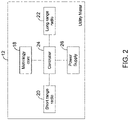
- FIG. 2 is a schematic block diagram of one of the utility meters 12.
- the utility meter 12 is configured to monitor consumption of a consumable that is provided by a utility provider and to provide messages that are related to consumption of the consumable to the head-end system 14. The messages may also provide diagnostic and other information to the head-end system.
- the utility meter 12 may be configured to join as a node in the local area mesh network 10 and to communicate with other utility meters 12 via the local area mesh network 10.
- the illustrative utility meter 12 includes a metrology core 18 that is configured to measure consumption of the consumable. If the utility meter 12 is an electricity meter, for example, the metrology core 18 is configured to measure an amount of electricity that is consumed. If the utility meter 12 is a gas meter or a water meter, the metrology core is configured to measure an amount of gas that is consumed or an amount of water that is consumed, respectively.
- the illustrative utility meter 12 includes a short-range radio 20 that is configured to communicate wirelessly over the local area mesh network 10 and a long-range radio 22 that is configured to communicate over the wide area network 11. In some instances, the long-range radio 22 is a cellular radio for communicating over a cellular telecommunications network, but this is not required. In some cases, the short-range radio 20 may have a communication range of less than one-quarter mile, and the long-range radio 22 may have a range of one half mile or greater, but this is just an example.
- a controller 24 is operably coupled to the metrology core 18, the short-range radio 20 and the long-range radio 22 and is configured to determine information. At least some of the information relates to consumption of the consumable as measured by the metrology core 18. In some cases, the information also includes diagnostic and/or performance information related to the operation of the corresponding utility meter 12. In one example, the controller is configured to check a performance of the local area mesh network 10 against one or more predetermined performance criteria. When the performance of the local area mesh network 10 meets a set of one or more predetermined performance criteria, the controller 24 is configured to communicate a first set of the information to the head-end system 14 using the short-range radio 20 via the local area mesh network 10.
- the controller 24 is configured to communicate a second set of the information to the head-end system 14 using the long-range radio 22 via the wide area network 11.
- the second set of the information may be different from the first set of the information.
- the second set of the information may be less than the first set of the information, such as only diagnostic information of the utility meter or just a summary of consumption information rather than more detailed consumption information, etc.
- the controller 24 of Figure 2 is further configured to repeatedly check the performance of the local area mesh network 10 against the one or more predetermined performance criteria, and when the performance of the local area mesh network 10 again meets the set of one or more predetermined performance criteria, the controller 24 is configured to communicate the first set of the information to the head-end system 14 using the short-range radio 20 via the local area mesh network 10 and stop communicating the second set of the information to the head-end system 14 using the long-range radio 22 via the wide area network 11.
- the one or more predetermined performance criteria of the local area mesh network 10 includes a maximum number of allowed hops in the local area mesh network 10, and wherein the performance of the local area mesh network 10 does not meet the set of one or more predetermined performance criteria when adding the utility meter 12 to the local area mesh network 10 would cause the number of hops of the local area mesh network 10 to exceed the maximum number of allowed hops.
- the one or more predetermined performance criteria of the local area mesh network 10 may include a signal quality metric and/or other performance metrics.
- the controller 24 may be configured to communicate the first set of the information in accordance with a first communication schedule.
- the controller 24 may be configured to communicate the second set of the information in accordance with a second communication schedule, wherein the second communication schedule communicates at least some of the information less frequently relative to the first communication schedule.
- the controller 24 may be configured to listen for nodes in one or more local area mesh networks 10 and to identify a measure of signal quality for each identified node.
- the controller 24 may be configured to join the local area mesh network 10 that includes the node with a highest measure of signal quality if allowed to join.
- the utility meter is allowed to join the local area mesh network when a hop limit of the local area mesh network has not yet been exceeded. If the utility meter 12 is not allowed to join the local area mesh network 10 that includes the node with the highest measure of signal quality, the controller 24 may be configured to join the local area mesh network 10 that includes the node with a next highest measure of signal quality if allowed to join.
- the controller 24 may be configured to communicate a first set of the information to the head-end system 14 using the short-range radio 20 via the local area mesh network 10. If the utility meter 12 is not allowed to join any of the local area mesh networks 10 discovered by the controller 24, the controller 24 may be configured to communicate a second set of the information to the head-end system 14 using the long-range radio 22 via the wide area network 11, wherein the second set of the information is different from the first set of the information.
- the second set of the information may include less information than the first set of the information.
- the first set of the information and the second set of the information each include diagnostic information for the utility meter 12.
- the following table provides examples of differences between the quantity and type of information transmitted using the short-range radio 20 versus the long-range radio 22: Short-range Long-range Communication many times in a day, low power consumption due to short-range. Communication once per a day or per week or once per 2 weeks based on configuration 15-min consumption interval data in the day, hourly consumption data in the day, hourly diagnostics and device status. Daily snapshot data for billing. Only Daily consumption data and Current Diagnostic data. ⁇ 50-bytes of payload are sent once a week.
- the utility meter 12 may include a power supply 26 that is operably coupled to the short-range radio 20, the long-range radio 22 and the controller 24.
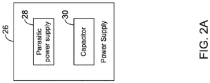
- the power supply 26 may vary, depending on which consumable the utility meter 12 is configured to measure. If the utility meter 12 is a gas meter or a water meter, the power supply 26 may include a battery. However, if the utility meter 12 is an electricity meter, and as seen in Figure 2A , the power supply 26 may include a parasitic power supply 28 that parasitically captures operating power from the power being measured, and a capacitor 30 that is charged by the parasitic power supply 28. The capacitor 30 may be configured to provide a limited amount of power to the electricity meter when the power being measured is not available.
- FIG. 3 is a flow diagram showing an illustrative method 40 of maintaining communication between a utility meter (such as the utility meter 12) and a head-end system (such as the head-end system 14) using an edge router (such as the edge router 16) that hosts a local area mesh network (such as the local area mesh network 10) that includes a plurality of utility meters.
- Each of the plurality of utility meters have both a short-range radio (such as the short-range radio 20) and a long-range radio (such as the long-range radio 22) and an ability to determine when to switch between using the short-range radio and the long-range radio.
- the illustrative method 40 includes monitoring a performance of the local area mesh network, as indicated at block 42.
- the utility meter uses its short-range radio to communicate to the head-end system using the local area mesh network, as indicated at block 44.
- the utility meter uses its long-range radio to communicate with the head-end system.
- the method 40 When using the long-range radio to communicate with the head-end system, the method 40 includes periodically turning the short-range radio on to ascertain a current performance of the local area mesh network, as indicated at block 46. The method 40 further includes reverting to using the short-range radio to communicate to the head-end system using the local area mesh network once the current performance of the local area mesh network has regained the performance threshold, as indicated at block 48. In some cases, and as indicated at block 50, a longer time interval between communications may be used when the utility meter is using the long-range radio to communicate with the head-end system relative to when the utility meter is using the short-range radio to communicate with the head-end system using the local area mesh network.
- messages may be sent in accordance with a schedule:
- first hop meters will join the edge routers within two minutes of power being restored.
- Second hop meters join the mesh network within about 2 minutes of the first hop meters joining. This process continues until, for example, 20 th hop meters have joined, which should be within about an hour of power being restored. It will be appreciated that the total number of hops allowed for the mesh network may be user configurable, and may not be set equal to 20.
- gas meters and water meters For gas meters and water meters, they will typically not be able to join as fast as electricity meters. Due to their battery limitations, gas meters and water meters may check for nearby mesh routers that host a mesh network using a discovery mechanism that executes, for example, once every 8 hours for a short period of time such as 30 seconds. If the gas meter or water meter does not discover any nearby mesh routers advertising their availability, the gas or water meter will immediately turn off its short-range radio and will continue to use the long-range radio. In some cases, the 8 hour time frame is configurable from 8 hours to 12 hours or 24 hours or even to once per week. This configuration may be set when the gas meter or the water meter is initially installed, for example.
- a new utility meter 12 may be installed and may thus be looking to join an existing local area mesh network 10.
- the new utility meter 12 will go into a listening mode in which the new utility meter 12 is listening for advertisements from any and all nearby mesh routers.
- the new utility meter 12 will identify all nearby mesh routers, including the mesh routers 16 and any utility meters 12, which can also function as routers, and will prepare a list of detected routers.
- the new utility meter 12 will select the mesh router 16 (or another utility meter 12) with the best signal strength, and perform a link check with that mesh router 16 (or another utility meter 12) by sending a LinkCheckRequest.
- the mesh router 16 or another utility meter 12
- a signal strength value is communicated during these link check.
- the new utility meter 12 can thus verify good two-way communication and will send a join request.
- the mesh router 16 or the another utility meter 12 will respond with join success. However, if the router 16 (or the another utility meter 12) is already at its highest mesh hop limit, the router 16 (or the another utility meter 12) will indicate this to the new utility meter 12 and thus cannot honor the join request. The new utility meter 12 will continue on to the next router 16 on its list of routers. If no routers 16 (or the another utility meter 12) are able to honor its join request, the new utility meter 12 switches to using its long-range radio 22 to communicate with the head-end system.
- FIGs 4 through 6 are schematic block diagrams of mesh networks, showing examples of how electricity meters, gas meters and water meters can be joined together in a mesh network.
- a local area mesh network 60 which may be considered as being an example of the local area mesh network 10, includes a first edge router 16a and a second edge router 16b.
- Each edge router 16 may serve as a mesh top node that connects mesh nodes to the head-end system 14 via a wired interface 62.
- each of the utility meters are electricity meters, as indicated by the EM# nomenclature.
- FIG. 5 is a schematic block diagram of a local area mesh network 70, which may be considered as being an example of the local area mesh network 10.
- the local area mesh network 70 includes both electricity meters, indicated by the EM# nomenclature, but also includes gas meters indicated by the GM# nomenclature as well as a water meter indicated by the WM1 nomenclature.
- gas meters are routing devices, but only route for other gas meters.
- the gas meters form a separate wing 72 in the mesh network 70.
- water meters do not have router functionality, and will be the last hop 74 in the mesh network 70. It will be appreciated that water meters have limited communication ability due to their typically being located in pits and having very small batteries.
- FIG. 6 is a schematic block diagram of a local area mesh network 80, which may be considered as being an example of the local area mesh network 10.
- the local area mesh network 80 is similar to the local area mesh network 60, but includes a break 82 that has formed between EM41 and EM42.
- the break 82 may occur for a variety of reasons. In this particular example, assume that the maximum number of hops is set equal to 20. Because of the break, EM42 now becomes hop number 21. Thus, either EM43 or the edge routers 16 will inform EM42 that EM42 cannot remain in the local area mesh network 80. In response, EM42 will look for another local area mesh network (same procedure as if EM42 was a newly installed meter) and will switch to its long-range radio if unsuccessful in finding a new local area network.
Landscapes
- Engineering & Computer Science (AREA)
- Computer Networks & Wireless Communication (AREA)
- Physics & Mathematics (AREA)
- General Physics & Mathematics (AREA)
- Signal Processing (AREA)
- Power Engineering (AREA)
- Fluid Mechanics (AREA)
- Mobile Radio Communication Systems (AREA)
- Telephonic Communication Services (AREA)
- Arrangements For Transmission Of Measured Signals (AREA)
Abstract
Description
- The present disclosure relates generally to utility meters. More particularly, the present disclosure relates to utility meters that communicate with a head-end system of a utility network.
- Utility meters are used to provide a measure of consumption for a variety of different utility providers. Utility meters include, for example, electricity meters that provide a measure of electricity consumed, gas meters that provide a measure of gas consumed and water meters that provide a measure of water consumed. Many utility meters include radios that permit the utility meters to communicate with a head-end system such as the utility itself. What would be desirable are utility meters that can communicate via a short-range radio over a mesh network and intelligently switch to a long-range radio when the mesh network becomes unavailable, inefficient or overloaded.
- The present disclosure relates to utility meters that are configured to intelligently switch between communicating using a short-range radio and a long-range radio. In one example, a utility meter is configured to monitor consumption of a consumable provided by a utility provider and to provide messages related to consumption of the consumable to a head-end system. The illustrative utility meter includes a metrology core that is configured to measure consumption of the consumable (e.g. electricity, gas or water), a short-range radio that is configured to communicate wirelessly over a local area mesh network. The illustrative utility meter further includes a long-range radio that is configured to communicate wirelessly over a wide area network. A controller is operably coupled to the metrology core, the short-range radio and the long-range radio. The controller is configured to determine information, at least some of which relates to consumption of the consumable measured by the metrology core. The controller is further configured to check a performance of the local area mesh network against one or more predetermined performance criteria. When the performance of the local area mesh network meets a set of one or more predetermined performance criteria, the controller is configured to communicate a first set of the information to the head-end system using the short-range radio via the local area mesh network. When the performance of the local area mesh network does not meet the set of one or more predetermined performance criteria, the controller is configured to communicate a second set of the information to the head-end system using the long-range radio via the wide area network. In some cases, the second set of the information is different from the first set of the information.
- In some cases, the controller may periodically check the performance of the local area mesh network against the one or more predetermined performance criteria. When the performance of the local area mesh network again meets the set of one or more predetermined performance criteria, the controller is configured to communicate the first set of the information to the head-end system using the short-range radio via the local area mesh network and stop communicating the second set of the information to the head-end system using the long-range radio via the wide area network. This may save power.
- In another example, a utility meter is configured to monitor consumption of a consumable provided by a utility provider, and to provide messages related to consumption of the consumable to a head-end system. The illustrative utility meter includes a metrology core that is configured to measure consumption of the consumable, a short-range radio that is configured to communicate wirelessly over a local area mesh network, a long-range radio that is configured to communicate wirelessly over a wide area network and a controller that is operably coupled to the metrology core, the short-range radio and the long-range radio. The controller is configured to determine information, at least some of which relates to consumption of the consumable measured by the metrology core. The controller is further configured to listen for nodes in one or more local area mesh networks, and to identify a measure of signal quality for each identified node. The controller is further configured to join the local area mesh network that includes the node with a highest measure of signal quality if allowed to join. In some cases, the utility meter is allowed to join the local area mesh network when a hop limit of the local area mesh network has not yet been exceeded. If the utility meter is not allowed to join the local area mesh network that includes the node with the highest measure of signal quality, the controller is configured to join the local area mesh network that includes the node with a next highest measure of signal quality if allowed to join. If the utility meter is allowed to join one of the local area mesh networks, the controller is configured to communicate a first set of the information to the head-end system using the short-range radio via the local area mesh network. If the utility meter is not allowed to join any of the local area mesh networks, the controller is configured to communicate a second set of the information to the head-end system using the long-range radio via the wide area network, wherein the second set of the information is different from the first set of the information.
- In another example, a method includes maintaining communication between a utility meter and a head-end system using an edge router that hosts a local area mesh network that includes a plurality of utility meters. Each of the plurality of utility meters has both a short-range radio and a long-range radio and an ability to determine when to switch between using the short-range radio and the long-range radio. A performance of the local area mesh network is monitored. When the performance of the local area mesh network remains at or above a performance threshold, the utility meter uses its short-range radio to communicate to the head-end system using the local area mesh network via the edge router. When the performance of the local area mesh network drops below the performance threshold, the utility meter uses its long-range radio to communicate with the head-end system. The utility meter may periodically turn on the short-range radio to ascertain a current performance of the local area mesh network, and revert to using the short-range radio to communicate to the head-end system using the local area mesh network once the current performance of the local area mesh network has regained the performance threshold.
- The preceding summary is provided to facilitate an understanding of some of the innovative features unique to the present disclosure and is not intended to be a full description. A full appreciation of the disclosure can be gained by taking the entire specification, claims, figures, and abstract as a whole.
- The disclosure may be more completely understood in consideration of the following description of various examples in connection with the accompanying drawings, in which:
-
Figure 1 is a schematic block diagram of an illustrative local area mesh network formed between a plurality of utility meters; -
Figure 2 is a schematic block diagram of an illustrative utility meter usable within the illustrative local area mesh network ofFigure 1 ; -
Figure 2A is a schematic block diagram of a portion of the illustrative utility meter ofFigure 2 ; -
Figure 3 is a flow diagram showing an illustrative method of maintaining communication between a utility meter and a head-end system; -
Figure 4 is a schematic block diagram of an illustrative local area mesh network formed between a plurality of utility meters; -
Figure 5 is a schematic block diagram of an illustrative local area mesh network formed between a plurality of utility meters; and -
Figure 6 is a schematic block diagram of an illustrative local area mesh network formed between a plurality of utility meters. - While the disclosure is amenable to various modifications and alternative forms, specifics thereof have been shown by way of example in the drawings and will be described in detail. It should be understood, however, that the intention is not to limit the disclosure to the particular examples described. On the contrary, the intention is to cover all modifications, equivalents, and alternatives falling within the spirit and scope of the disclosure.
- The following description should be read with reference to the drawings, in which like elements in different drawings are numbered in like fashion. The drawings, which are not necessarily to scale, depict examples that are not intended to limit the scope of the disclosure. Although examples are illustrated for the various elements, those skilled in the art will recognize that many of the examples provided have suitable alternatives that may be utilized.
- All numbers are herein assumed to be modified by the term "about", unless the content clearly dictates otherwise. The recitation of numerical ranges by endpoints includes all numbers subsumed within that range (e.g., 1 to 5 includes 1, 1.5, 2, 2.75, 3, 3.80, 4, and 5).
- As used in this specification and the appended claims, the singular forms "a", "an", and "the" include the plural referents unless the content clearly dictates otherwise. As used in this specification and the appended claims, the term "or" is generally employed in its sense including "and/or" unless the content clearly dictates otherwise.
- It is noted that references in the specification to "an embodiment", "some embodiments", "other embodiments", etc., indicate that the embodiment described may include a particular feature, structure, or characteristic, but every embodiment may not necessarily include the particular feature, structure, or characteristic. Moreover, such phrases are not necessarily referring to the same embodiment. Further, when a particular feature, structure, or characteristic is described in connection with an embodiment, it is contemplated that the feature, structure, or characteristic is described in connection with an embodiment, it is contemplated that the feature, structure, or characteristic may be applied to other embodiments whether or not explicitly described unless clearly stated to the contrary.
-
Figure 1 is a schematic block diagram of an illustrative localarea mesh network 10 that includes a number ofutility meters 12. Theutility meters 12 are individually labeled as 12a, 12b, 12c, 12d through 12n. Theutility meters 12 may individually represent, for example, electricity meters, gas meters or water meters, although in some instances there are differences in how each of the different types ofutility meters 12 are able to communicate, as will be discussed. The localarea mesh network 10 may include any number ofutility meters 12, although in some cases, the localarea mesh network 10 may impose a limit on how many "hops" are permitted within the localarea mesh network 10 as efficiency declines as the total number of hops increases. While not expressly shown inFigure 1 , each of theutility meters 12 may include a short-range radio that enables theutility meters 12 to communicate with each other and ultimately communicate with a head-end system 14 via arouter 16. The head-end system 14 may be considered as representing the utility that produces the consumable that is measured by theutility meter 12. Accordingly, the head-end system 14 may represent, for example, an electric utility, a gas utility or a water utility. In some cases, the head-end system 14 may represent a computer system located at the particular utility. In some instances, the head-end system 14 may represent a cloud-based computer system that is operably coupled with the utility, or at least with a computer system located at the utility. - In sending a communication, each
utility meter 12 is attempting to ultimately provide that communication to the head-end system 14. Aparticular utility meter 12 will communicate with the head-end system 14 via the localarea mesh network 10 in a manner that is most efficient and that has an acceptable signal-to-noise ratio. To illustrate, theutility meter 12b may communicate with the head-end system 14 by wirelessly sending a message to theutility meter 12a. Theutility meter 12a may then repeat the message to the head-end system 14. Theutility meter 12c may communicate with the head-end system 14 by wirelessly sending a message to theutility meter 12a, which then repeats the message to the head-end system 14 if that route is determined to be efficient. Alternatively, theutility meter 12c may communicate with the head-end system 14 by wirelessly sending a message to theutility meter 12b, which then repeats the message to theutility meter 12a, if that particular route is more efficient. Theutility meter 12a then repeats the message to the head-end system 14. It a particular utility meter goes down and drops out of the mesh network, the remaining utility meters may re-route their communication path through the remaining utility meters, providing a robust communication network. These are just examples. The localarea mesh network 10 is called a mesh network in part because communications are not always linear, but can move laterally and dynamically within the mesh network in order to provide efficient and robust communication between each of theutility meters 12 and the head-end system 14. - The
utility meters 12 also include a long-range radio that is configured to communicate over awide area network 11. To illustrate, theutility meter 12n may use its long-range radio to communicate over the wide area network 11 (shown in dashed lines). Thewide area network 11 may allow theutility meter 12n to communicate with the head-end system 14 independent from the local area mesh network. In some cases, the long-range radio may communication directly with the head-end system via a cellular or other wide area network. In some cases, the long-range radio may communicate with a gateway (e.g. router 16) that relays the communication messages received from the long-range radio to the head-end system via the Internet backbone. - In some cases, the long rage radio may communicate using cellular communication technology. In some cases, the long-range radio may be implemented in accordance with one of NB-IoT, LTE, CAT-M1, LoRaWAN, SigFox, or 5G. In some cases, the long-range radio may use a proprietary long-range communication protocol on Sub-GHz frequency bands like 169MHz and 433MHz license free frequency bands. In some cases, the long-range radio may be provided by an ultra low power long-range transceiver model number SX1276 available from Semtech. These are just examples.
-
Figure 2 is a schematic block diagram of one of theutility meters 12. Theutility meter 12 is configured to monitor consumption of a consumable that is provided by a utility provider and to provide messages that are related to consumption of the consumable to the head-end system 14. The messages may also provide diagnostic and other information to the head-end system. Theutility meter 12 may be configured to join as a node in the localarea mesh network 10 and to communicate withother utility meters 12 via the localarea mesh network 10. - The
illustrative utility meter 12 includes ametrology core 18 that is configured to measure consumption of the consumable. If theutility meter 12 is an electricity meter, for example, themetrology core 18 is configured to measure an amount of electricity that is consumed. If theutility meter 12 is a gas meter or a water meter, the metrology core is configured to measure an amount of gas that is consumed or an amount of water that is consumed, respectively. Theillustrative utility meter 12 includes a short-range radio 20 that is configured to communicate wirelessly over the localarea mesh network 10 and a long-range radio 22 that is configured to communicate over thewide area network 11. In some instances, the long-range radio 22 is a cellular radio for communicating over a cellular telecommunications network, but this is not required. In some cases, the short-range radio 20 may have a communication range of less than one-quarter mile, and the long-range radio 22 may have a range of one half mile or greater, but this is just an example. - A
controller 24 is operably coupled to themetrology core 18, the short-range radio 20 and the long-range radio 22 and is configured to determine information. At least some of the information relates to consumption of the consumable as measured by themetrology core 18. In some cases, the information also includes diagnostic and/or performance information related to the operation of thecorresponding utility meter 12. In one example, the controller is configured to check a performance of the localarea mesh network 10 against one or more predetermined performance criteria. When the performance of the localarea mesh network 10 meets a set of one or more predetermined performance criteria, thecontroller 24 is configured to communicate a first set of the information to the head-end system 14 using the short-range radio 20 via the localarea mesh network 10. When the performance of the localarea mesh network 10 does not meet the set of one or more predetermined performance criteria, thecontroller 24 is configured to communicate a second set of the information to the head-end system 14 using the long-range radio 22 via thewide area network 11. The second set of the information may be different from the first set of the information. In some cases, the second set of the information may be less than the first set of the information, such as only diagnostic information of the utility meter or just a summary of consumption information rather than more detailed consumption information, etc. - The
controller 24 ofFigure 2 is further configured to repeatedly check the performance of the localarea mesh network 10 against the one or more predetermined performance criteria, and when the performance of the localarea mesh network 10 again meets the set of one or more predetermined performance criteria, thecontroller 24 is configured to communicate the first set of the information to the head-end system 14 using the short-range radio 20 via the localarea mesh network 10 and stop communicating the second set of the information to the head-end system 14 using the long-range radio 22 via thewide area network 11. - In some instances, the one or more predetermined performance criteria of the local
area mesh network 10 includes a maximum number of allowed hops in the localarea mesh network 10, and wherein the performance of the localarea mesh network 10 does not meet the set of one or more predetermined performance criteria when adding theutility meter 12 to the localarea mesh network 10 would cause the number of hops of the localarea mesh network 10 to exceed the maximum number of allowed hops. The one or more predetermined performance criteria of the localarea mesh network 10 may include a signal quality metric and/or other performance metrics. - In some cases, when the performance of the local
area mesh network 10 meets the set of one or more predetermined performance criteria, thecontroller 24 may be configured to communicate the first set of the information in accordance with a first communication schedule. When the performance of the localarea mesh network 10 does not meet the set of one or more predetermined performance criteria, thecontroller 24 may be configured to communicate the second set of the information in accordance with a second communication schedule, wherein the second communication schedule communicates at least some of the information less frequently relative to the first communication schedule. - In some instances, the
controller 24 may be configured to listen for nodes in one or more localarea mesh networks 10 and to identify a measure of signal quality for each identified node. Thecontroller 24 may be configured to join the localarea mesh network 10 that includes the node with a highest measure of signal quality if allowed to join. In some cases, the utility meter is allowed to join the local area mesh network when a hop limit of the local area mesh network has not yet been exceeded. If theutility meter 12 is not allowed to join the localarea mesh network 10 that includes the node with the highest measure of signal quality, thecontroller 24 may be configured to join the localarea mesh network 10 that includes the node with a next highest measure of signal quality if allowed to join. If theutility meter 12 is allowed to join one of the localarea mesh networks 10, thecontroller 24 may be configured to communicate a first set of the information to the head-end system 14 using the short-range radio 20 via the localarea mesh network 10. If theutility meter 12 is not allowed to join any of the localarea mesh networks 10 discovered by thecontroller 24, thecontroller 24 may be configured to communicate a second set of the information to the head-end system 14 using the long-range radio 22 via thewide area network 11, wherein the second set of the information is different from the first set of the information. - In some cases, as detailed above, the second set of the information may include less information than the first set of the information. In some cases, the first set of the information and the second set of the information each include diagnostic information for the
utility meter 12. To illustrate, the following table provides examples of differences between the quantity and type of information transmitted using the short-range radio 20 versus the long-range radio 22:Short-range Long-range Communication many times in a day, low power consumption due to short-range. Communication once per a day or per week or once per 2 weeks based on configuration 15-min consumption interval data in the day, hourly consumption data in the day, hourly diagnostics and device status. Daily snapshot data for billing. Only Daily consumption data and Current Diagnostic data. < 50-bytes of payload are sent once a week. 4-bytes of daily consumption reading + 2-bytes of diagnostics every day for 7 Daily events and metrology log books reading/publishing. Few 3-4K bytes of data every day. days in a week. 7*6 = 42-bytes + header information. Always used if available Switched to Long-range only if 2-days of no connectivity to Short-range communication (number of days configurable) If short-range is unavailable due to any above-described reasons, then device will be move to Long-range. Once in a week, short-range radio is switched on to check Mesh connectivity and scanning of routers. If nearby routers are detected, then a link check is performed to confirm the good connectivity both ways. If link looks good, then switches from Long-range to short-range mesh radio Switches to Long-range when mesh network size is growing above a limit (> 20 hops) to avoid latency and loading the intermediate routers. Beyond 20 hops mesh network will not accept any children so long-range radio is used during these periods of mesh communication rejection due to hop limit reach - The
utility meter 12 may include apower supply 26 that is operably coupled to the short-range radio 20, the long-range radio 22 and thecontroller 24. Thepower supply 26 may vary, depending on which consumable theutility meter 12 is configured to measure. If theutility meter 12 is a gas meter or a water meter, thepower supply 26 may include a battery. However, if theutility meter 12 is an electricity meter, and as seen inFigure 2A , thepower supply 26 may include aparasitic power supply 28 that parasitically captures operating power from the power being measured, and acapacitor 30 that is charged by theparasitic power supply 28. Thecapacitor 30 may be configured to provide a limited amount of power to the electricity meter when the power being measured is not available. -
Figure 3 is a flow diagram showing anillustrative method 40 of maintaining communication between a utility meter (such as the utility meter 12) and a head-end system (such as the head-end system 14) using an edge router (such as the edge router 16) that hosts a local area mesh network (such as the local area mesh network 10) that includes a plurality of utility meters. Each of the plurality of utility meters have both a short-range radio (such as the short-range radio 20) and a long-range radio (such as the long-range radio 22) and an ability to determine when to switch between using the short-range radio and the long-range radio. - The
illustrative method 40 includes monitoring a performance of the local area mesh network, as indicated atblock 42. When the performance of the local area mesh network remains at or above a performance threshold, the utility meter uses its short-range radio to communicate to the head-end system using the local area mesh network, as indicated at block 44. When the performance of the local area mesh network drops below the performance threshold, the utility meter uses its long-range radio to communicate with the head-end system. - When using the long-range radio to communicate with the head-end system, the
method 40 includes periodically turning the short-range radio on to ascertain a current performance of the local area mesh network, as indicated atblock 46. Themethod 40 further includes reverting to using the short-range radio to communicate to the head-end system using the local area mesh network once the current performance of the local area mesh network has regained the performance threshold, as indicated atblock 48. In some cases, and as indicated atblock 50, a longer time interval between communications may be used when the utility meter is using the long-range radio to communicate with the head-end system relative to when the utility meter is using the short-range radio to communicate with the head-end system using the local area mesh network. - In some cases, a power disruption may interfere with the local
area mesh network 10. It will be appreciated that how theutility meters 12 respond to the power disruption will depend at least in part upon whether theutility meter 12 is an electricity meter, a gas meter or a water meter. If theutility meter 12 is an electricity meter, theutility meter 12 will immediately switch over to its long-range radio 22. Theutility meter 12 will send short messages infrequently until power is regained. Thecapacitor 30 is configured to provide enough energy to transmit six or eight messages over the long-range radio 22 and stay alive for a minimum of 24 to 48 hours. In some instances, the first message may be transmitted one hour after the power is disrupted. Subsequent messages may be sent on an ever-decreasing frequency. As an example, the message transmit time (the time between subsequent transmissions) may be set equal to:
- X is the time at which the power was disrupted, and
- N is an integer equal to 0, 1, 2, etc.
- In this example, messages may be sent in accordance with a schedule:
- First message sent at X + 1 hours
- Second message sent at X + 2 hours
- Third message sent at X + 4 hours
- Fourth message sent at X + 16 hours
- Fifth message sent at X + 32 hours, and so on.
- When power returns, electricity meters immediately sense that power has returned, and will periodically look for available mesh networks. In one example, first hop meters will join the edge routers within two minutes of power being restored. Second hop meters join the mesh network within about 2 minutes of the first hop meters joining. This process continues until, for example, 20th hop meters have joined, which should be within about an hour of power being restored. It will be appreciated that the total number of hops allowed for the mesh network may be user configurable, and may not be set equal to 20.
- For gas meters and water meters, they will typically not be able to join as fast as electricity meters. Due to their battery limitations, gas meters and water meters may check for nearby mesh routers that host a mesh network using a discovery mechanism that executes, for example, once every 8 hours for a short period of time such as 30 seconds. If the gas meter or water meter does not discover any nearby mesh routers advertising their availability, the gas or water meter will immediately turn off its short-range radio and will continue to use the long-range radio. In some cases, the 8 hour time frame is configurable from 8 hours to 12 hours or 24 hours or even to once per week. This configuration may be set when the gas meter or the water meter is initially installed, for example.
- In some cases, a
new utility meter 12 may be installed and may thus be looking to join an existing localarea mesh network 10. In one example, thenew utility meter 12 will go into a listening mode in which thenew utility meter 12 is listening for advertisements from any and all nearby mesh routers. Thenew utility meter 12 will identify all nearby mesh routers, including themesh routers 16 and anyutility meters 12, which can also function as routers, and will prepare a list of detected routers. Thenew utility meter 12 will select the mesh router 16 (or another utility meter 12) with the best signal strength, and perform a link check with that mesh router 16 (or another utility meter 12) by sending a LinkCheckRequest. In response, the mesh router 16 (or another utility meter 12) will return a LinkCheckResponse. In some cases, a signal strength value is communicated during these link check. Thenew utility meter 12 can thus verify good two-way communication and will send a join request. - If the
mesh router 16 or the anotherutility meter 12 is not at its highest mesh hop limit, themesh router 16 or the anotherutility meter 12 will respond with join success. However, if the router 16 (or the another utility meter 12) is already at its highest mesh hop limit, the router 16 (or the another utility meter 12) will indicate this to thenew utility meter 12 and thus cannot honor the join request. Thenew utility meter 12 will continue on to thenext router 16 on its list of routers. If no routers 16 (or the another utility meter 12) are able to honor its join request, thenew utility meter 12 switches to using its long-range radio 22 to communicate with the head-end system. -
Figures 4 through 6 are schematic block diagrams of mesh networks, showing examples of how electricity meters, gas meters and water meters can be joined together in a mesh network. InFigure 4 , a localarea mesh network 60, which may be considered as being an example of the localarea mesh network 10, includes afirst edge router 16a and asecond edge router 16b. Eachedge router 16 may serve as a mesh top node that connects mesh nodes to the head-end system 14 via awired interface 62. InFigure 4 , each of the utility meters are electricity meters, as indicated by the EM# nomenclature. It can be seen that EM1, EM3, EM5 through EM40 and EM43 are aligned under thefirst edge router 16a and EM2, EM4, EM6 through EM41 and EM42 are aligned under thesecond edge router 16b.Figure 4 includes the indications of hop numbers as well, to illustrate how that is determined. -
Figure 5 is a schematic block diagram of a localarea mesh network 70, which may be considered as being an example of the localarea mesh network 10. The localarea mesh network 70 includes both electricity meters, indicated by the EM# nomenclature, but also includes gas meters indicated by the GM# nomenclature as well as a water meter indicated by the WM1 nomenclature. In this example, gas meters are routing devices, but only route for other gas meters. In some cases, as illustrated, the gas meters form aseparate wing 72 in themesh network 70. In this example, water meters do not have router functionality, and will be thelast hop 74 in themesh network 70. It will be appreciated that water meters have limited communication ability due to their typically being located in pits and having very small batteries. -
Figure 6 is a schematic block diagram of a localarea mesh network 80, which may be considered as being an example of the localarea mesh network 10. The localarea mesh network 80 is similar to the localarea mesh network 60, but includes abreak 82 that has formed between EM41 and EM42. Thebreak 82 may occur for a variety of reasons. In this particular example, assume that the maximum number of hops is set equal to 20. Because of the break, EM42 now becomeshop number 21. Thus, either EM43 or theedge routers 16 will inform EM42 that EM42 cannot remain in the localarea mesh network 80. In response, EM42 will look for another local area mesh network (same procedure as if EM42 was a newly installed meter) and will switch to its long-range radio if unsuccessful in finding a new local area network. - Having thus described several illustrative embodiments of the present disclosure, those of skill in the art will readily appreciate that yet other embodiments may be made and used within the scope of the claims hereto attached. It will be understood, however, that this disclosure is, in many respects, only illustrative. Changes may be made in details, particularly in matters of shape, size, arrangement of parts, and exclusion and order of steps, without exceeding the scope of the disclosure. The disclosure's scope is, of course, defined in the language in which the appended claims are expressed.
Claims (15)
- A utility meter that is configured to monitor consumption of a consumable provided by a utility provider, and to provide messages related to consumption of the consumable to a head-end system, the utility meter comprising:a metrology core configured to measure consumption of the consumable;a short-range radio configured to communicate wirelessly over a local area mesh network;a long-range radio configured to communicate over a wide area network;a controller operably coupled to the metrology core, the short-range radio and the long-range radio, the controller configured to:determine information at least some of which relates to consumption of the consumable measured by the metrology core;checking a performance of the local area mesh network against one or more predetermined performance criteria;when the performance of the local area mesh network meets a set of one or more predetermined performance criteria, communicate a first set of the information to the head-end system using the short-range radio via the local area mesh network;when the performance of the local area mesh network does not meet the set of one or more predetermined performance criteria:communicate a second set of the information to the head-end system using the long-range radio via the wide area network, wherein the second set of the information is different from the first set of the information;check the performance of the local area mesh network against the one or more predetermined performance criteria, and when the performance of the local area mesh network meets the set of one or more predetermined performance criteria:communicate the first set of the information to the head-end system using the short-range radio via the local area mesh network; andstop communicating the second set of the information to the head-end system using the long-range radio via the wide area network.
- The utility meter of claim 1, wherein the one or more predetermined performance criteria of the local area mesh network includes a maximum number of allowed hops in the local area mesh network, and wherein the performance of the local area mesh network does not meet the set of one or more predetermined performance criteria when adding the utility meter to the local area mesh network would cause the number of hops of the local area mesh network to exceed the maximum number of allowed hops.
- The utility meter of claim 1, wherein the set of one or more predetermined performance criteria of the local area mesh network comprises a signal quality metric.
- The utility meter of claim 1, wherein the long-range radio comprises a cellular radio for communicating over a cellular telecommunications network.
- The utility meter of claim 1, wherein the short-range radio has a communication range of less than one-quarter mile, and the long-range radio has a range of one half mile or greater.
- The utility meter of claim 1, wherein the second set of the information comprises less information than the first set of the information.
- The utility meter of claim 1, wherein the utility meter is configured to join as a node in the local area mesh network and communicate with other utility meters via the local area mesh network.
- The utility meter of claim 1, wherein:when the performance of the local area mesh network meets the set of one or more predetermined performance criteria, the controller communicates the first set of the information in accordance with a first communication schedule; andwhen the performance of the local area mesh network does not meet the set of one or more predetermined performance criteria, the controller communicates the second set of the information in accordance with a second communication schedule, wherein the second communication schedule communicates information less frequently relative to the first communication schedule.
- The utility meter of claim 1, wherein the consumable comprises a gas, and the metrology core is configured to measure consumption of the gas.
- The utility meter of claim 1, wherein the consumable comprises water, and the metrology core is configured to measure consumption of the water.
- The utility meter of claim 1, wherein the utility meter comprises an electricity meter, and a power supply, wherein the power supply comprises:a parasitic power supply captured from the power being measured; anda capacitor that is charged by the parasitic power supply, the capacitor configured to provide a limited amount of power to the electricity meter when the power being measured is not available.
- The utility meter of claim 1, wherein the utility meter comprises a gas meter or a water meter, and a power supply, wherein the power supply comprises a battery.
- The utility meter of claim 1, wherein the first set of the information and the second set of the information each comprise diagnostic information of the utility meter.
- A method of maintaining communication between a utility meter and a head-end system using an edge router that hosts a local area mesh network that includes a plurality of utility meters, each of the plurality of utility meters having both a short-range radio and a long-range radio and an ability to determine when to switch between using the short-range radio and the long-range radio, the method comprising:monitoring a performance of the local area mesh network;when the performance of the local area mesh network remains at or above a performance threshold, the utility meter uses its short-range radio to communicate to the head-end system using the local area mesh network;when the performance of the local area mesh network drops below the performance threshold, the utility meter uses its long-range radio to communicate with the head-end system; andwhen using the long-range radio to communicate with the head-end system, periodically turning the short-range radio on to ascertain a current performance of the local area mesh network, and reverting to using the short-range radio to communicate to the head-end system using the local area mesh network once the current performance of the local area mesh network has regained the performance threshold.
- The method of claim 14, further comprising using a longer time interval between communications when the utility meter is using the long-range radio to communicate with the head-end system than when the utility meter is using the short-range radio to communicate with the head-end system using the local area mesh network.
Applications Claiming Priority (1)
| Application Number | Priority Date | Filing Date | Title |
|---|---|---|---|
| US17/165,566 US11356753B1 (en) | 2021-02-02 | 2021-02-02 | Utility meter with short and long-range radios with intelligent switching therebetween |
Publications (2)
| Publication Number | Publication Date |
|---|---|
| EP4036527A1 true EP4036527A1 (en) | 2022-08-03 |
| EP4036527B1 EP4036527B1 (en) | 2025-12-03 |
Family
ID=79601810
Family Applications (1)
| Application Number | Title | Priority Date | Filing Date |
|---|---|---|---|
| EP22151305.4A Active EP4036527B1 (en) | 2021-02-02 | 2022-01-13 | Utility meter with short and long-range radios with intelligent switching therebetween |
Country Status (3)
| Country | Link |
|---|---|
| US (1) | US11356753B1 (en) |
| EP (1) | EP4036527B1 (en) |
| CN (1) | CN114923534B (en) |
Cited By (1)
| Publication number | Priority date | Publication date | Assignee | Title |
|---|---|---|---|---|
| IT202300016686A1 (en) * | 2023-08-04 | 2025-02-04 | Italgas Reti S P A | GAS METER |
Citations (2)
| Publication number | Priority date | Publication date | Assignee | Title |
|---|---|---|---|---|
| US20160021525A1 (en) * | 2014-07-16 | 2016-01-21 | Itron, Inc. | Network discovery by battery powered devices |
| KR20170128974A (en) * | 2016-05-16 | 2017-11-24 | 주식회사 엠씨티 | No supply electricity facility meter management method and system using smart utility network communication |
Family Cites Families (21)
| Publication number | Priority date | Publication date | Assignee | Title |
|---|---|---|---|---|
| US7185131B2 (en) | 1999-06-10 | 2007-02-27 | Amron Technologies, Inc. | Host-client utility meter systems and methods for communicating with the same |
| US7170881B2 (en) * | 2002-10-29 | 2007-01-30 | Nokia Corporation | Method and apparatus providing user programmable, personalized location-aware services |
| US7994934B2 (en) * | 2004-10-05 | 2011-08-09 | Electro Industries/Gauge Tech | Meter having a communication interface for receiving and interfacing with a communication device |
| US20080106434A1 (en) * | 2006-10-18 | 2008-05-08 | Arad Measuring Technologies Ltd. | Data collection system and method for collecting utility consumption data |
| NZ579331A (en) * | 2007-02-02 | 2012-12-21 | Aztech Associates Inc | Utility monitoring device, system and method |
| WO2009027617A1 (en) * | 2007-08-28 | 2009-03-05 | John Stanton | A utility metering system incorporating a private/public radio network |
| US8878690B2 (en) * | 2009-06-23 | 2014-11-04 | Badger Meter, Inc. | AMR transmitter and method using multiple radio messages |
| CN102256334A (en) * | 2010-05-21 | 2011-11-23 | 鼎桥通信技术有限公司 | Method for finding radio local area network in mobile network |
| CN101917732B (en) * | 2010-07-16 | 2012-10-31 | 中国科学院计算技术研究所 | Wireless flow judging method |
| CN101945435A (en) * | 2010-09-29 | 2011-01-12 | 上海顶竹通讯技术有限公司 | Network with a plurality of access networks and access and switching method |
| US20140369394A1 (en) * | 2011-09-21 | 2014-12-18 | Nokia Corporation | Beam-steering configurations and tests |
| EP2592871B1 (en) * | 2011-11-11 | 2014-05-28 | Itron, Inc. | Routing communications based on link quality |
| CN104678167B (en) * | 2012-08-22 | 2019-01-25 | 华立科技股份有限公司 | A kind of intelligent electric energy meter and utility meter kilowatt meter reading-out system |
| WO2014126910A1 (en) | 2013-02-15 | 2014-08-21 | Cygnus Broadband, Inc. | Smart grid portal election |
| US9729943B2 (en) * | 2013-03-13 | 2017-08-08 | Trimble Inc. | Utility meter reporting network |
| EP2830366A1 (en) * | 2013-07-23 | 2015-01-28 | Thomson Licensing | Method of management of a wireless interface of a device and corresponding wireless device |
| US10045291B2 (en) * | 2014-07-16 | 2018-08-07 | Itron Global Sarl | Relay functionality of battery powered devices |
| RU156053U1 (en) * | 2015-02-24 | 2015-10-27 | Общество с ограниченной ответственностью "Внедренческий Научно-Технический Центр "Уралжелдоравтоматизация" | SYSTEM OF SITUATIONAL CONTROL AT RAILWAY TRANSFER |
| CN105357727B (en) * | 2015-10-16 | 2017-10-24 | 深圳市安拓浦科技有限公司 | A kind of mobile network and local network automatic switching method |
| US9929771B2 (en) | 2016-02-05 | 2018-03-27 | Apana Inc. | Low power, centralized data collection |
| FR3052868B1 (en) * | 2016-06-20 | 2021-01-01 | Gulplug | ELECTRICAL ENERGY METERING DEVICE |
-
2021
- 2021-02-02 US US17/165,566 patent/US11356753B1/en active Active
-
2022
- 2022-01-13 EP EP22151305.4A patent/EP4036527B1/en active Active
- 2022-01-19 CN CN202210063051.3A patent/CN114923534B/en active Active
Patent Citations (2)
| Publication number | Priority date | Publication date | Assignee | Title |
|---|---|---|---|---|
| US20160021525A1 (en) * | 2014-07-16 | 2016-01-21 | Itron, Inc. | Network discovery by battery powered devices |
| KR20170128974A (en) * | 2016-05-16 | 2017-11-24 | 주식회사 엠씨티 | No supply electricity facility meter management method and system using smart utility network communication |
Non-Patent Citations (3)
| Title |
|---|
| JAIN AMIT ET AL: "Multi-communication technology based AMI for smart metering in India", 2019 IEEE 5TH INTERNATIONAL CONFERENCE FOR CONVERGENCE IN TECHNOLOGY (I2CT), IEEE, 29 March 2019 (2019-03-29), pages 1 - 6, XP033739448, DOI: 10.1109/I2CT45611.2019.9033704 * |
| JAIN P C: "Trends in smart power grid communication and networking", 2015 INTERNATIONAL CONFERENCE ON SIGNAL PROCESSING AND COMMUNICATION (ICSC), IEEE, 16 March 2015 (2015-03-16), pages 374 - 379, XP033172004, DOI: 10.1109/ICSPCOM.2015.7150680 * |
| SHAHIN FARAHANI: "ZIGBEE WIRELESS NETWORKS AND TRANSCEIVERS", 13 February 2009 (2009-02-13), pages 1 - 364, XP055424846, Retrieved from the Internet <URL:http://www.chiaraburatti.org/uploads/teaching/ZigBee-Libro.pdf> [retrieved on 20171114] * |
Cited By (2)
| Publication number | Priority date | Publication date | Assignee | Title |
|---|---|---|---|---|
| IT202300016686A1 (en) * | 2023-08-04 | 2025-02-04 | Italgas Reti S P A | GAS METER |
| EP4503677A1 (en) * | 2023-08-04 | 2025-02-05 | Italgas Reti S.p.A. | Gas meter and method of transmitting measurements |
Also Published As
| Publication number | Publication date |
|---|---|
| CN114923534B (en) | 2026-03-20 |
| EP4036527B1 (en) | 2025-12-03 |
| US11356753B1 (en) | 2022-06-07 |
| CN114923534A (en) | 2022-08-19 |
Similar Documents
| Publication | Publication Date | Title |
|---|---|---|
| JP5128007B2 (en) | Method and apparatus for determining the rank of a node in a multi-hop wireless network | |
| CN108173752B (en) | LORAWAN gateway and control method thereof | |
| CN103999500B (en) | communication system and automatic meter reading system | |
| EP3977773B1 (en) | Managing outage detections and reporting | |
| CN113261348B (en) | Signal repeater equipment operable in low power repeater operation mode | |
| CA2602289A1 (en) | Using a fixed network wireless data collection system to improve utility responsiveness to power outages | |
| JP6342915B2 (en) | Intelligent network operation | |
| CN108966305A (en) | A kind of LORA relaying ad hoc network method | |
| CN106297235B (en) | Routing establishment method and meter reading method for centralized meter reading of low-voltage power users | |
| CN111541463A (en) | Dynamic media switching in co-located PLC and RF networks | |
| CN119155760A (en) | Communication link switching method of heterogeneous network | |
| CN120881639A (en) | Multi-network convergence gateway system supporting satellite, cellular and broadband and narrowband ad hoc networks | |
| CN115150302A (en) | An end-to-end satellite network performance measurement method | |
| EP4036527B1 (en) | Utility meter with short and long-range radios with intelligent switching therebetween | |
| JP7072731B1 (en) | Communication systems, aggregates, central devices, terminals, communication methods and programs | |
| CN111182555A (en) | Short-distance multi-node relay type self-adaptive wireless networking method | |
| CN101232420A (en) | Wireless networking method of electric power data acquisition system | |
| CN119052880A (en) | LoRa ad hoc network communication forwarding node selection method | |
| CN101867515B (en) | Data packet transmission method and terminal equipment | |
| CN102821390B (en) | Adaptive dynamic channel allocation method for mobile multimedia in Internet of things | |
| JP5372303B1 (en) | Wireless terminal device, wireless mesh network, and communication method | |
| CN210518382U (en) | Gateway system based on LORA and NB-IOT | |
| CN101610568A (en) | Preserve mesh point power of battery method and system in the mesh network | |
| CN110808846B (en) | Communication method and device with complementary advantages of multi-master communication technology | |
| CN205123419U (en) | Data transmitting system |
Legal Events
| Date | Code | Title | Description |
|---|---|---|---|
| PUAI | Public reference made under article 153(3) epc to a published international application that has entered the european phase |
Free format text: ORIGINAL CODE: 0009012 |
|
| STAA | Information on the status of an ep patent application or granted ep patent |
Free format text: STATUS: REQUEST FOR EXAMINATION WAS MADE |
|
| 17P | Request for examination filed |
Effective date: 20220113 |
|
| AK | Designated contracting states |
Kind code of ref document: A1 Designated state(s): AL AT BE BG CH CY CZ DE DK EE ES FI FR GB GR HR HU IE IS IT LI LT LU LV MC MK MT NL NO PL PT RO RS SE SI SK SM TR |
|
| P01 | Opt-out of the competence of the unified patent court (upc) registered |
Effective date: 20230414 |
|
| STAA | Information on the status of an ep patent application or granted ep patent |
Free format text: STATUS: EXAMINATION IS IN PROGRESS |
|
| 17Q | First examination report despatched |
Effective date: 20240206 |
|
| GRAP | Despatch of communication of intention to grant a patent |
Free format text: ORIGINAL CODE: EPIDOSNIGR1 |
|
| STAA | Information on the status of an ep patent application or granted ep patent |
Free format text: STATUS: GRANT OF PATENT IS INTENDED |
|
| INTG | Intention to grant announced |
Effective date: 20250716 |
|
| GRAS | Grant fee paid |
Free format text: ORIGINAL CODE: EPIDOSNIGR3 |
|
| GRAA | (expected) grant |
Free format text: ORIGINAL CODE: 0009210 |
|
| STAA | Information on the status of an ep patent application or granted ep patent |
Free format text: STATUS: THE PATENT HAS BEEN GRANTED |
|
| AK | Designated contracting states |
Kind code of ref document: B1 Designated state(s): AL AT BE BG CH CY CZ DE DK EE ES FI FR GB GR HR HU IE IS IT LI LT LU LV MC MK MT NL NO PL PT RO RS SE SI SK SM TR |
|
| REG | Reference to a national code |
Ref country code: CH Ref legal event code: F10 Free format text: ST27 STATUS EVENT CODE: U-0-0-F10-F00 (AS PROVIDED BY THE NATIONAL OFFICE) Effective date: 20251203 Ref country code: GB Ref legal event code: FG4D |
|
| REG | Reference to a national code |
Ref country code: DE Ref legal event code: R096 Ref document number: 602022025934 Country of ref document: DE |
|
| REG | Reference to a national code |
Ref country code: IE Ref legal event code: FG4D |
|
| REG | Reference to a national code |
Ref country code: NL Ref legal event code: MP Effective date: 20251203 |
|
| PGFP | Annual fee paid to national office [announced via postgrant information from national office to epo] |
Ref country code: GB Payment date: 20260126 Year of fee payment: 5 |
|
| PG25 | Lapsed in a contracting state [announced via postgrant information from national office to epo] |
Ref country code: ES Free format text: LAPSE BECAUSE OF FAILURE TO SUBMIT A TRANSLATION OF THE DESCRIPTION OR TO PAY THE FEE WITHIN THE PRESCRIBED TIME-LIMIT Effective date: 20251203 |
|
| REG | Reference to a national code |
Ref country code: LT Ref legal event code: MG9D |
|
| PG25 | Lapsed in a contracting state [announced via postgrant information from national office to epo] |
Ref country code: NO Free format text: LAPSE BECAUSE OF FAILURE TO SUBMIT A TRANSLATION OF THE DESCRIPTION OR TO PAY THE FEE WITHIN THE PRESCRIBED TIME-LIMIT Effective date: 20260303 |
|
| PGFP | Annual fee paid to national office [announced via postgrant information from national office to epo] |
Ref country code: DE Payment date: 20260127 Year of fee payment: 5 |
|
| PG25 | Lapsed in a contracting state [announced via postgrant information from national office to epo] |
Ref country code: HR Free format text: LAPSE BECAUSE OF FAILURE TO SUBMIT A TRANSLATION OF THE DESCRIPTION OR TO PAY THE FEE WITHIN THE PRESCRIBED TIME-LIMIT Effective date: 20251203 Ref country code: FI Free format text: LAPSE BECAUSE OF FAILURE TO SUBMIT A TRANSLATION OF THE DESCRIPTION OR TO PAY THE FEE WITHIN THE PRESCRIBED TIME-LIMIT Effective date: 20251203 |
|
| PGFP | Annual fee paid to national office [announced via postgrant information from national office to epo] |
Ref country code: AT Payment date: 20260301 Year of fee payment: 5 |
|
| PG25 | Lapsed in a contracting state [announced via postgrant information from national office to epo] |
Ref country code: RS Free format text: LAPSE BECAUSE OF FAILURE TO SUBMIT A TRANSLATION OF THE DESCRIPTION OR TO PAY THE FEE WITHIN THE PRESCRIBED TIME-LIMIT Effective date: 20260303 |
|
| PGFP | Annual fee paid to national office [announced via postgrant information from national office to epo] |
Ref country code: FR Payment date: 20260127 Year of fee payment: 5 |
|
| PG25 | Lapsed in a contracting state [announced via postgrant information from national office to epo] |
Ref country code: PL Free format text: LAPSE BECAUSE OF FAILURE TO SUBMIT A TRANSLATION OF THE DESCRIPTION OR TO PAY THE FEE WITHIN THE PRESCRIBED TIME-LIMIT Effective date: 20251203 |
|
| PG25 | Lapsed in a contracting state [announced via postgrant information from national office to epo] |
Ref country code: LV Free format text: LAPSE BECAUSE OF FAILURE TO SUBMIT A TRANSLATION OF THE DESCRIPTION OR TO PAY THE FEE WITHIN THE PRESCRIBED TIME-LIMIT Effective date: 20251203 |
|
| PG25 | Lapsed in a contracting state [announced via postgrant information from national office to epo] |
Ref country code: BG Free format text: LAPSE BECAUSE OF FAILURE TO SUBMIT A TRANSLATION OF THE DESCRIPTION OR TO PAY THE FEE WITHIN THE PRESCRIBED TIME-LIMIT Effective date: 20251203 |
|
| REG | Reference to a national code |
Ref country code: AT Ref legal event code: MK05 Ref document number: 1864040 Country of ref document: AT Kind code of ref document: T Effective date: 20251203 |
|
| PG25 | Lapsed in a contracting state [announced via postgrant information from national office to epo] |
Ref country code: NL Free format text: LAPSE BECAUSE OF FAILURE TO SUBMIT A TRANSLATION OF THE DESCRIPTION OR TO PAY THE FEE WITHIN THE PRESCRIBED TIME-LIMIT Effective date: 20251203 |
|
| PG25 | Lapsed in a contracting state [announced via postgrant information from national office to epo] |
Ref country code: LT Free format text: LAPSE BECAUSE OF FAILURE TO SUBMIT A TRANSLATION OF THE DESCRIPTION OR TO PAY THE FEE WITHIN THE PRESCRIBED TIME-LIMIT Effective date: 20251203 |
|
| PG25 | Lapsed in a contracting state [announced via postgrant information from national office to epo] |
Ref country code: SM Free format text: LAPSE BECAUSE OF FAILURE TO SUBMIT A TRANSLATION OF THE DESCRIPTION OR TO PAY THE FEE WITHIN THE PRESCRIBED TIME-LIMIT Effective date: 20251203 |
|
| PG25 | Lapsed in a contracting state [announced via postgrant information from national office to epo] |
Ref country code: IT Free format text: LAPSE BECAUSE OF FAILURE TO SUBMIT A TRANSLATION OF THE DESCRIPTION OR TO PAY THE FEE WITHIN THE PRESCRIBED TIME-LIMIT Effective date: 20251203 |
|
| PG25 | Lapsed in a contracting state [announced via postgrant information from national office to epo] |
Ref country code: AT Free format text: LAPSE BECAUSE OF FAILURE TO SUBMIT A TRANSLATION OF THE DESCRIPTION OR TO PAY THE FEE WITHIN THE PRESCRIBED TIME-LIMIT Effective date: 20251203 |
|
| PG25 | Lapsed in a contracting state [announced via postgrant information from national office to epo] |
Ref country code: EE Free format text: LAPSE BECAUSE OF FAILURE TO SUBMIT A TRANSLATION OF THE DESCRIPTION OR TO PAY THE FEE WITHIN THE PRESCRIBED TIME-LIMIT Effective date: 20251203 |
|
| PG25 | Lapsed in a contracting state [announced via postgrant information from national office to epo] |
Ref country code: PT Free format text: LAPSE BECAUSE OF FAILURE TO SUBMIT A TRANSLATION OF THE DESCRIPTION OR TO PAY THE FEE WITHIN THE PRESCRIBED TIME-LIMIT Effective date: 20260406 Ref country code: IS Free format text: LAPSE BECAUSE OF FAILURE TO SUBMIT A TRANSLATION OF THE DESCRIPTION OR TO PAY THE FEE WITHIN THE PRESCRIBED TIME-LIMIT Effective date: 20260403 |
|
| PG25 | Lapsed in a contracting state [announced via postgrant information from national office to epo] |
Ref country code: CZ Free format text: LAPSE BECAUSE OF FAILURE TO SUBMIT A TRANSLATION OF THE DESCRIPTION OR TO PAY THE FEE WITHIN THE PRESCRIBED TIME-LIMIT Effective date: 20251203 |
|
| PG25 | Lapsed in a contracting state [announced via postgrant information from national office to epo] |
Ref country code: SK Free format text: LAPSE BECAUSE OF FAILURE TO SUBMIT A TRANSLATION OF THE DESCRIPTION OR TO PAY THE FEE WITHIN THE PRESCRIBED TIME-LIMIT Effective date: 20251203 |
|
| PG25 | Lapsed in a contracting state [announced via postgrant information from national office to epo] |
Ref country code: SE Free format text: LAPSE BECAUSE OF FAILURE TO SUBMIT A TRANSLATION OF THE DESCRIPTION OR TO PAY THE FEE WITHIN THE PRESCRIBED TIME-LIMIT Effective date: 20251203 |