EP4036402A1 - Blade for a wind turbine - Google Patents
Blade for a wind turbine Download PDFInfo
- Publication number
- EP4036402A1 EP4036402A1 EP21382087.1A EP21382087A EP4036402A1 EP 4036402 A1 EP4036402 A1 EP 4036402A1 EP 21382087 A EP21382087 A EP 21382087A EP 4036402 A1 EP4036402 A1 EP 4036402A1
- Authority
- EP
- European Patent Office
- Prior art keywords
- connection terminal
- lightning
- blade
- conductive layer
- power supply
- Prior art date
- Legal status (The legal status is an assumption and is not a legal conclusion. Google has not performed a legal analysis and makes no representation as to the accuracy of the status listed.)
- Granted
Links
Images


Classifications
-
- F—MECHANICAL ENGINEERING; LIGHTING; HEATING; WEAPONS; BLASTING
- F03—MACHINES OR ENGINES FOR LIQUIDS; WIND, SPRING, OR WEIGHT MOTORS; PRODUCING MECHANICAL POWER OR A REACTIVE PROPULSIVE THRUST, NOT OTHERWISE PROVIDED FOR
- F03D—WIND MOTORS
- F03D1/00—Wind motors with rotation axis substantially parallel to the air flow entering the rotor
- F03D1/06—Rotors
- F03D1/065—Rotors characterised by their construction elements
- F03D1/0675—Rotors characterised by their construction elements of the blades
-
- F—MECHANICAL ENGINEERING; LIGHTING; HEATING; WEAPONS; BLASTING
- F03—MACHINES OR ENGINES FOR LIQUIDS; WIND, SPRING, OR WEIGHT MOTORS; PRODUCING MECHANICAL POWER OR A REACTIVE PROPULSIVE THRUST, NOT OTHERWISE PROVIDED FOR
- F03D—WIND MOTORS
- F03D80/00—Details, components or accessories not provided for in groups F03D1/00 - F03D17/00
- F03D80/30—Lightning protection
-
- F—MECHANICAL ENGINEERING; LIGHTING; HEATING; WEAPONS; BLASTING
- F03—MACHINES OR ENGINES FOR LIQUIDS; WIND, SPRING, OR WEIGHT MOTORS; PRODUCING MECHANICAL POWER OR A REACTIVE PROPULSIVE THRUST, NOT OTHERWISE PROVIDED FOR
- F03D—WIND MOTORS
- F03D80/00—Details, components or accessories not provided for in groups F03D1/00 - F03D17/00
- F03D80/40—Ice detection; De-icing means
-
- F—MECHANICAL ENGINEERING; LIGHTING; HEATING; WEAPONS; BLASTING
- F05—INDEXING SCHEMES RELATING TO ENGINES OR PUMPS IN VARIOUS SUBCLASSES OF CLASSES F01-F04
- F05B—INDEXING SCHEME RELATING TO WIND, SPRING, WEIGHT, INERTIA OR LIKE MOTORS, TO MACHINES OR ENGINES FOR LIQUIDS COVERED BY SUBCLASSES F03B, F03D AND F03G
- F05B2240/00—Components
- F05B2240/20—Rotors
- F05B2240/30—Characteristics of rotor blades, i.e. of any element transforming dynamic fluid energy to or from rotational energy and being attached to a rotor
- F05B2240/307—Blade tip, e.g. winglets
-
- F—MECHANICAL ENGINEERING; LIGHTING; HEATING; WEAPONS; BLASTING
- F05—INDEXING SCHEMES RELATING TO ENGINES OR PUMPS IN VARIOUS SUBCLASSES OF CLASSES F01-F04
- F05B—INDEXING SCHEME RELATING TO WIND, SPRING, WEIGHT, INERTIA OR LIKE MOTORS, TO MACHINES OR ENGINES FOR LIQUIDS COVERED BY SUBCLASSES F03B, F03D AND F03G
- F05B2280/00—Materials; Properties thereof
- F05B2280/60—Properties or characteristics given to material by treatment or manufacturing
- F05B2280/6003—Composites; e.g. fibre-reinforced
-
- Y—GENERAL TAGGING OF NEW TECHNOLOGICAL DEVELOPMENTS; GENERAL TAGGING OF CROSS-SECTIONAL TECHNOLOGIES SPANNING OVER SEVERAL SECTIONS OF THE IPC; TECHNICAL SUBJECTS COVERED BY FORMER USPC CROSS-REFERENCE ART COLLECTIONS [XRACs] AND DIGESTS
- Y02—TECHNOLOGIES OR APPLICATIONS FOR MITIGATION OR ADAPTATION AGAINST CLIMATE CHANGE
- Y02E—REDUCTION OF GREENHOUSE GAS [GHG] EMISSIONS, RELATED TO ENERGY GENERATION, TRANSMISSION OR DISTRIBUTION
- Y02E10/00—Energy generation through renewable energy sources
- Y02E10/70—Wind energy
- Y02E10/72—Wind turbines with rotation axis in wind direction
Definitions
- the present invention relates to a blade for a wind turbine, in particular, to blades comprising an ice formation prevention system and a lightning protection system.
- Blades for a wind turbine with an ice formation prevention system and a lightning protection system are known in the art. Taking into account that wind turbines and in particular, the blades of these turbines have high probabilities of being struck by a lightning, it is necessary to equip the blade with a lightning protection system for minimizing the effect of the lightning in the blade, in particular in the electrical elements contained in the blade and/or in the wind turbine.
- blades including conductive layers integrated into the shell structure of the blade, in particular in the leading edge of the blade are known for preventing the formation of ice which adversely affects the efficiency of the wind turbine.
- the presence of an ice formation prevention systems in a blade could also affect the efficiency of the lightning protection system.
- the conductive layer can attract lightning and thus damage the blade, particularly on the blade tip region comprising approximately last five meters of the blade, and mostly on end of the conductive layer which is closer to the blade tip. Damage of the conductive layer may result in a limited performance or complete failure of the ice formation prevention system. Solutions to reduce damage in the conductive layer due to lightning striking are known in the art, as for example WO2018/095649A1 .
- WO2018/095649A1 describes a blade for a wind turbine comprising a trailing edge and a leading edge longitudinally extending from the blade tip to the blade root, a lightning protection system with a lightning receptor arranged on the blade tip for receiving lightning and a lightning down conductor for conducting a lightning current received by the lightning receptor to the blade root, and an ice formation prevention system with a conductive layer arranged along the leading edge having a first end oriented to the blade tip and a second end oriented to the blade root, and a first connection terminal placed on the first end of the conductive layer and a second connection terminal placed on the second end of the conductive layer for electrically connecting the conductive layer with a power supply unit and therefore heating the conductive layer for preventing ice formation.
- the first connection terminal of the conductive layer is electrically connected with the lightning down conductor such that their potential are equalized, minimizing damage of lightning striking.
- the blade has several lightning receptors arranged on the blade tip region for attracting lightning and protecting the conductive layer of the ice formation prevention system.
- the object of the invention is to provide a blade for a wind turbine as defined in the claims.
- An aspect of the invention relates to a blade for a wind turbine comprising a trailing edge and a leading edge longitudinally extending from the blade tip to the blade root, a lightning protection system with at least one lightning receptor arranged on the blade tip for receiving lightning and at least one lightning down conductor for conducting a lightning current received by the lightning receptor to the blade root, and an ice formation prevention system with a conductive layer arranged along the leading edge having a first end oriented to the blade tip and a second end oriented to the blade root, and a first connection terminal placed on the first end of the conductive layer and a second connection terminal placed on the second end of the conductive layer for electrically connecting the conductive layer with a power supply unit, the first connection terminal of the conductive layer is electrically connected with the lightning down conductor, wherein the first connection terminal partially contacts the conductive layer and have a rear section connected to the conductive layer and a front section that longitudinally extends towards the blade tip.
- the first connection terminal of the conductive layer is oversized towards the blade tip to attract lightning and thus preventing them to directly strike onto the conductive layer avoiding damage of the conductive layer.
- the oversized first connection terminal is arranged on the blade tip region and allows to reduce the number of lightning receptors required to be arranged on the blade tip region for attract lightning and protect the conductive layer of the ice formation prevention system.
- the oversized first connection terminal is cheaper and requires a less complicate manufacturing process than placing lightning receptors on the blade tip region.
- FIG. 1 shows a blade 1 for a wind turbine comprising a lightning protection system 10 and an ice formation prevention system 20 according to the prior art.
- the blade 1 has a trailing edge 2 and a leading edge 3 longitudinally extending from the blade tip 4 to the blade root 5.
- a dashed line represents the profile of the blade 1.
- the lightning protection system 10 comprises a lightning receptor 11 arranged on the blade tip 4 for receiving lightning and a lightning down conductor 12 for conducting a lightning current received by the lightning receptor 11 to the blade root 5.
- the lightning current is conducted from the the blade root 5 to a ground terminal through the hub (not represented) .
- the ice formation prevention system 20 comprises a conductive layer 21 which is arranged along the leading edge 3 and which have a first end 22 oriented to the blade tip 4 and a second end 23 oriented to the blade root 5.
- the ice formation prevention system 20 further comprises a first connection terminal 24 placed on the first end 22 of the conductive layer 21 and a second connection terminal 25 placed on the second end 23 of the conductive layer 21 for electrically connecting the conductive layer 21 with a power supply unit (not shown in Figure 1 ) and for heating the conductive layer 21.
- the conductive layer 21 is a heating mat comprising a conductive material (for example carbon fibers) for deicing the ice formed onto the blade 1. Said conductive layer 21 attracts lightning that may damage the blade 1, so the first connection terminal 24 of the conductive layer 21 is electrically connected with the lightning down conductor 12, ensuring the equipotentiality of the ice formation prevention system 20 and the lightning protection system 10.
- the blade 1 also comprises other lightning receptors 13 arranged on the trailing edge 2 of the blade 1 to prevent lightning to strike the conductive layer 21.
- FIG 2 shows a blade 1 for a wind turbine according to the invention.
- the blade 1 is identical to the blade 1 described above in Figure 1 but has a first connection terminal 24 which is oversized towards the blade tip 4 to attract lightning and thus preventing them to directly strike onto the first end 22 of the conductive layer 21.
- the first connection terminal 24 partially contacts the conductive layer 21 and have a rear section 241 connected to the conductive layer 21 and a front section 242 that longitudinally extends towards the blade tip 4.
- the front section 242 creates a conductive mass close to the blade tip 4 where lightning may directly strike, thus preventing them to strike onto the first end 22 of the conductive layer 21.
- the first connection terminal 24 is electrically connected with the lightning down conductor 12, thus the first connection terminal 24 works as a lightning receptor.
- the first connection terminal 24 is electrically connected with the lightning down conductor 12 through a conductor 28.
- FIG 4 shows another embodiment of the blade shown in Figures 2 and 3 .
- the blade 1 further comprises another lightning receptor 14 arranged parallel to the first connection terminal 24 on the trailing edge 2 of the blade 1.
- the first connection terminal 24 works as a lightning receptor on the leading edge 3 preventing lightning striking onto the conductive layer 21, but lightning may strike on the trailing edge 2, on the part opposed where the first end 22 of conductive layer 21 is placed, thus the another lightning receptor 14 is placed on said zone of the trailing edge 2.
- Figures 5 to 7 show other embodiments of first connection terminal 24, the conductive layer 21 and the electrical connection with lightning down conductor 12. Said embodiments show that other lightning receptor 14 arranged on the trailing edge 2 of the blade; however said lightning receptor 14 is not necessary for preventing lightning strike onto the conductive layer 21 of the leading edge 3 as describe in Figure 3 .
- the first connection terminal 24 is electrically connected with the lightning down conductor 12 and the second connection terminal 25 is electrically connected with a power supply wire 27, the lightning down conductor 12 and the power supply wire 27 are connected to the power supply unit.
- the lightning down conductor 12 works as a power supply wire for heating the conductive layer 21.
- the first connection terminal 24 is electrically connected with a first power supply wire 26 and the second connection terminal 25 is electrically connected with a second power supply wire 27, the power supply wires 26 and 27 are connected to the power supply unit, and the first power supply wire 26 is connected to the lightning down conductor 12 by a surge protection device 15.
- the lightning down conductor 12 does not work as a power supply wire for heating the conductive layer 21, and the conductive layer 21 has independent power supply wires for heating the layer 21.
- the surge protection device 15 protects the ice formation prevention system 20 when a surge due to a lightning strike occurs, reducing the current passing through the power wires 26 and 27.
- the surge protection device 15 works as a switch that closes during the short time of the surge, i.e. it works as an open switch preventing the passage of current when a certain voltage is not exceeded and it works as a closed switch when a certain voltage is exceeded.
- the overvoltage currents can flow to the ground via lightning down conductor 12 or via the power supply wires 26 and 27. This circuit only lasts for the duration of the surge, normally some microseconds up to few milliseconds.
- the surge protection device 15 can be based on a spark gap technology, or varistor technology (MOV) or any other know suitable device used to limit voltage differences between conductors.
- MOV varistor technology
- Embodiments of Figures 6 and 7 are equivalent to Figure 5 describe above but show a conductive layer 21 comprising a first piece 211 arranged in parallel with a second piece 212, each piece 211 and 212 is arranged at one side of the leading edge 3.
- a blade 1 for a wind turbine is manufactured in two pieces.
- the blade comprises an upper shell and a lower shell that are built independently in a vacuum infusion process and after that they are assembled to obtain the blade 1.
- the first piece 211 is arranged on the upper shell of the blade 1 and the second piece 212 is arranged on the lower shell of the blade 1.
- Embodiments of Figures 6 and 7 further show a first connection terminal 24 comprising a first part 243 arranged at one side of the leading edge 3 and partially contacting the first piece 211 of the conductive layer 21, and a second part 244 arranged at the other side of the leading edge 3 and partially contacting the second piece 212 of the conductive layer 21.
- the first part 243 of the first connection terminal 24 is electrically connected with the lightning down conductor 12 through a first conductor 281 and the second part 244 of the first connection terminal 24 is electrically connected with the lightning down conductor 12 through a second conductor 282.
- Each part 243 and 244 have the rear section 241 connected to the conductive layer 21 and the front section 242 that longitudinally extends towards the blade tip 4.
- the first conductor 281 and the second conductor 282 are electrically connected with the first power supply wire 26, and the lightning down conductor 12 is electrically connected with the first power supply wire 26 through the surge protection device 15.
- the first conductor 281 and the second conductor 282 may be an extension of the power supply wire 26.
- Having a conductive layer 21 with two pieces 211 and 212 may vary the lightning striking onto the connection terminal 24, and thus the first conductor 281 and second conductor 282 allows a balanced current injection on the lightning down conductor 12 avoiding electrical arcs.
- Embodiment of Figure 6 shows a first connection terminal 24 which is a single piece terminal having the first part 243 and the second part 244 while embodiment of Figure 7 shows a first connection terminal 24 which is a two pieces terminal having the first part 243 and the second part 244.
- This latter solution simplifies the manufacturing of a blade 1 manufactured in two parts, commonly the upper shell and the lower shell.
- the conductive layer 21 is a heating mat comprising biaxial carbon fabrics and is integrated into the shell of the blade 1 or is placed onto the shell (at both sides of the upper and lower shell separated by the leading edge 3).
- the conductive layer 21 is a composite sheet having carbon biaxial fibers with a density of 100-600 g/m2.
- the conductive layer 21 may be obtained during manufacturing of the shell and thus being part of the shell, or can be placed onto the surface of the shell after the shell is obtained.
- the conductive layer 21 is a single heating mat extending along the leading edge 3 of the blade 1 from the blade tip 4 to the blade root 5, and for example occupies approximately 2/3 parts of the leading edge 3.
- the conductive layer 21 has two or more heating mats extending along the leading edge 3 of the blade 1; in said case, each heating mat has connection terminals at their ends for receiving power supply, but only the first connection terminal 24 of the first heating mat arranged on the blade tip region is required to be oversized according to the invention.
- the terminals 24 and 25 are placed at the ends 22 and 23 of the conductive layer 21, however they may be placed close to the ends 22 and 23.
- the first terminal 24 is required to be arranged on the first end 22 as close as possible to the blade tip 4
- the second terminal 25 is not required to be placed exactly on the second end 23, and may be placed close to said second end 23.
- connection terminals 24 and 25 have a shape similar to the shape of the conductive layer 21.
- the connection terminals 24 and 25 and the conductive layer 21 have a rectangular shape.
- the connection terminals 24 and 25 are flat connection terminals. More preferably, the connection terminals 24 and 25 are flat metallic sheets.
- Power supply wires 26 and 27 are standard low voltage wires used to transfer a power supply from the blade root 5 to the connection terminals 24 and 25. Instead or wires other flat or mesh metallic conductors may be used.
- the connector 28 and the first conductor 281 and the second conductor 282 are preferably standard low voltage wires.
- FIGS. 12 and 13 show a single lightning down conductor 12, however, multiple lightning down conductors may be used, in said case, each lightning down conductor is electrically connected to the conductive layer 21 as describe above.
- the power supply wires 26 and 27 and lightning down conductor 12 are arranged inside the shell of the blade 1.
- the wires 26 and 27 and the conductor 12 are arranged onto the inner surface of the shell, or are arranged inside the shell, for example onto a shear web.
- the terminals 24 and 25 of the conductive layer 21 are placed within the shell or placed onto the outer surface of the shell, thus a conductive element 29 is arranged on the rear section 241 of the first connection terminal 24 to transmit electrical currents from the terminal 24 to the lightning down conductor 12 or to the first power supply wire 26 and the lightning down conductor 12.
- the second connection terminal 25 has also another conductive element 29 to transmit electrical currents from terminal 25 to the second power supply wire 27 (see Figure 8 ).
- Said conductive elements are preferably made of copper, brass or aluminum.
- the front section 242 of the first connection terminal 24 longitudinally extends from the first end 22 of the conductive layer 21 a length "a" between 200-1.500 mm. This length allows the lightning to strike onto the connection terminal 24 far from first end 22 of the conductive layer 21.
- the rear section 241 of the first connection terminal 24 connecting the conductive layer 21 with the first connection terminal 24 has a length "d" of at least 30 mm. This minimum length "d" where layer 21 overlaps terminal 24 guarantees a proper electrical transmission between the first connection terminal 24 and the conductive layer 21.
- the first connection terminal 24 has a width "b" equal or greater than the width "c" of the conductive layer 21. Having a width "b" of the first connection terminal 24 greater than the width "c” of the conductive layer 21 allows the first connection terminal 24 to transversely project from the conductive layer 21, thus the conductive element 29 is placed on the rear section 241 of the first connection terminal 24 for electrically connecting the first end 22 of conductive layer 21 with the lightning down conductor 12 or the first power supply wire 26, through the conductor 28.
- the relationship b/c>1 also allows a better performance of connection terminal 24 to attach lightning strikes.
- the width "b" of the first connection terminal 24 can be reduced by enlarging the length "a" of the front section 242 of the first connection terminal 24.
- the length "a” and “d” of the first connection terminal 24 is parallel to the longitudinal axis of the blade 1 which longitudinally extends from the blade tip 4 to the blade root 5.
- the length “a” extends towards the blade tip 4 from the first end 22 of the conductive layer 21 to the front end of the connection terminal 24.
- the length “d” extends towards the blade root 5 from the first end 22 of the conductive layer 21 to the rear end of the connection terminal 24, thus the conductive layer 21 overlaps the rear section 241 of the first connection terminal 24.
- the width "b" of the first connection terminal 24 and width "c" of the conductive layer 21 are transversal to the longitudinal axis of the blade 1.
- connection terminal 24 have a thickness between 100 ⁇ m to 1000 ⁇ m.
- the first connection terminal 24 is a rectangular metallic sheet with a length "a" of 500mm, a width "b” of 700mm, a length “d” of 50 mm, and a thickness of 0,15mm.
- the conductive layer 21 is a rectangular heating mat of a width "c" of 600mm and a thickness of 0,3 mm.
Landscapes
- Engineering & Computer Science (AREA)
- Life Sciences & Earth Sciences (AREA)
- Sustainable Development (AREA)
- Sustainable Energy (AREA)
- Chemical & Material Sciences (AREA)
- Combustion & Propulsion (AREA)
- Mechanical Engineering (AREA)
- General Engineering & Computer Science (AREA)
- Wind Motors (AREA)
- Hydraulic Turbines (AREA)
Abstract
Description
- The present invention relates to a blade for a wind turbine, in particular, to blades comprising an ice formation prevention system and a lightning protection system.
- Blades for a wind turbine with an ice formation prevention system and a lightning protection system are known in the art. Taking into account that wind turbines and in particular, the blades of these turbines have high probabilities of being struck by a lightning, it is necessary to equip the blade with a lightning protection system for minimizing the effect of the lightning in the blade, in particular in the electrical elements contained in the blade and/or in the wind turbine.
- On the other hand, blades including conductive layers integrated into the shell structure of the blade, in particular in the leading edge of the blade, are known for preventing the formation of ice which adversely affects the efficiency of the wind turbine.
- The presence of an ice formation prevention systems in a blade could also affect the efficiency of the lightning protection system. Moreover, the conductive layer can attract lightning and thus damage the blade, particularly on the blade tip region comprising approximately last five meters of the blade, and mostly on end of the conductive layer which is closer to the blade tip. Damage of the conductive layer may result in a limited performance or complete failure of the ice formation prevention system. Solutions to reduce damage in the conductive layer due to lightning striking are known in the art, as for example
WO2018/095649A1 . -
WO2018/095649A1 describes a blade for a wind turbine comprising a trailing edge and a leading edge longitudinally extending from the blade tip to the blade root, a lightning protection system with a lightning receptor arranged on the blade tip for receiving lightning and a lightning down conductor for conducting a lightning current received by the lightning receptor to the blade root, and an ice formation prevention system with a conductive layer arranged along the leading edge having a first end oriented to the blade tip and a second end oriented to the blade root, and a first connection terminal placed on the first end of the conductive layer and a second connection terminal placed on the second end of the conductive layer for electrically connecting the conductive layer with a power supply unit and therefore heating the conductive layer for preventing ice formation. The first connection terminal of the conductive layer is electrically connected with the lightning down conductor such that their potential are equalized, minimizing damage of lightning striking. The blade has several lightning receptors arranged on the blade tip region for attracting lightning and protecting the conductive layer of the ice formation prevention system. - The object of the invention is to provide a blade for a wind turbine as defined in the claims.
- An aspect of the invention relates to a blade for a wind turbine comprising a trailing edge and a leading edge longitudinally extending from the blade tip to the blade root, a lightning protection system with at least one lightning receptor arranged on the blade tip for receiving lightning and at least one lightning down conductor for conducting a lightning current received by the lightning receptor to the blade root, and an ice formation prevention system with a conductive layer arranged along the leading edge having a first end oriented to the blade tip and a second end oriented to the blade root, and a first connection terminal placed on the first end of the conductive layer and a second connection terminal placed on the second end of the conductive layer for electrically connecting the conductive layer with a power supply unit, the first connection terminal of the conductive layer is electrically connected with the lightning down conductor, wherein the first connection terminal partially contacts the conductive layer and have a rear section connected to the conductive layer and a front section that longitudinally extends towards the blade tip.
- Thus, the first connection terminal of the conductive layer is oversized towards the blade tip to attract lightning and thus preventing them to directly strike onto the conductive layer avoiding damage of the conductive layer. Moreover, the oversized first connection terminal is arranged on the blade tip region and allows to reduce the number of lightning receptors required to be arranged on the blade tip region for attract lightning and protect the conductive layer of the ice formation prevention system. The oversized first connection terminal is cheaper and requires a less complicate manufacturing process than placing lightning receptors on the blade tip region.
- This and other advantages and features of the invention will become evident in view of the figures and of the detailed description of the invention.
-
-
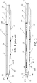
Figure 1 shows a blade for a wind turbine comprising a lightning protection system and an ice formation prevention system according to the prior art. -
Figure 2 shows a blade for a wind turbine comprising a lightning protection system and an ice formation prevention system according to the invention. -
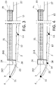
Figure 3 shows an enlarged view of the blade tip region of the blade ofFigure 2 . -
Figures 4 to 7 show enlarged views of other embodiments of the blade. -
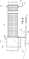
Figure 8 show an schematic view of the first connection terminal partially contacting the conductive layer and illustrating comparative measures between both elements. -
Figure 1 shows ablade 1 for a wind turbine comprising alightning protection system 10 and an iceformation prevention system 20 according to the prior art. Theblade 1 has atrailing edge 2 and a leadingedge 3 longitudinally extending from theblade tip 4 to theblade root 5. A dashed line represents the profile of theblade 1. - The
lightning protection system 10 comprises alightning receptor 11 arranged on theblade tip 4 for receiving lightning and a lightning downconductor 12 for conducting a lightning current received by thelightning receptor 11 to theblade root 5. The lightning current is conducted from the theblade root 5 to a ground terminal through the hub (not represented) . - The ice
formation prevention system 20 comprises aconductive layer 21 which is arranged along the leadingedge 3 and which have afirst end 22 oriented to theblade tip 4 and asecond end 23 oriented to theblade root 5. The iceformation prevention system 20 further comprises afirst connection terminal 24 placed on thefirst end 22 of theconductive layer 21 and asecond connection terminal 25 placed on thesecond end 23 of theconductive layer 21 for electrically connecting theconductive layer 21 with a power supply unit (not shown inFigure 1 ) and for heating theconductive layer 21. - The
conductive layer 21 is a heating mat comprising a conductive material (for example carbon fibers) for deicing the ice formed onto theblade 1. Saidconductive layer 21 attracts lightning that may damage theblade 1, so thefirst connection terminal 24 of theconductive layer 21 is electrically connected with the lightning downconductor 12, ensuring the equipotentiality of the iceformation prevention system 20 and thelightning protection system 10. Theblade 1 also comprisesother lightning receptors 13 arranged on thetrailing edge 2 of theblade 1 to prevent lightning to strike theconductive layer 21. However, most of the lightning strike occur at thefirst end 22 of theconductive layer 21 which is closer to theblade tip 4, due to electric field intensification at that point, and thelightning receptor 11 of theblade tip 4 and theother lightning receptors 13 of thetrailing edge 2 do not proper prevent lightning occur in said point. In order to protect theconductive layer 21 several lightning receptors need to be placed on the blade tip region increasing the cost of the blade and a complex manufacturing process. -
Figure 2 shows ablade 1 for a wind turbine according to the invention. Theblade 1 is identical to theblade 1 described above inFigure 1 but has afirst connection terminal 24 which is oversized towards theblade tip 4 to attract lightning and thus preventing them to directly strike onto thefirst end 22 of theconductive layer 21. - As shown in detail in
Figure 3 , thefirst connection terminal 24 partially contacts theconductive layer 21 and have arear section 241 connected to theconductive layer 21 and afront section 242 that longitudinally extends towards theblade tip 4. Thefront section 242 creates a conductive mass close to theblade tip 4 where lightning may directly strike, thus preventing them to strike onto thefirst end 22 of theconductive layer 21. As stated above, thefirst connection terminal 24 is electrically connected with the lightning downconductor 12, thus thefirst connection terminal 24 works as a lightning receptor. Thefirst connection terminal 24 is electrically connected with the lightning downconductor 12 through aconductor 28. -
Figure 4 shows another embodiment of the blade shown inFigures 2 and3 . Preferably, theblade 1 further comprises anotherlightning receptor 14 arranged parallel to thefirst connection terminal 24 on thetrailing edge 2 of theblade 1. As explained above, thefirst connection terminal 24 works as a lightning receptor on the leadingedge 3 preventing lightning striking onto theconductive layer 21, but lightning may strike on thetrailing edge 2, on the part opposed where thefirst end 22 ofconductive layer 21 is placed, thus theanother lightning receptor 14 is placed on said zone of thetrailing edge 2. -
Figures 5 to 7 show other embodiments offirst connection terminal 24, theconductive layer 21 and the electrical connection with lightning downconductor 12. Said embodiments show thatother lightning receptor 14 arranged on thetrailing edge 2 of the blade; however saidlightning receptor 14 is not necessary for preventing lightning strike onto theconductive layer 21 of the leadingedge 3 as describe inFigure 3 . - As shown in the embodiments of
Figures 3 and 4 , thefirst connection terminal 24 is electrically connected with the lightning downconductor 12 and thesecond connection terminal 25 is electrically connected with apower supply wire 27, the lightning downconductor 12 and thepower supply wire 27 are connected to the power supply unit. In said case, the lightning downconductor 12 works as a power supply wire for heating theconductive layer 21. - Alternatively, as shown in the embodiment of
Figure 5 , thefirst connection terminal 24 is electrically connected with a firstpower supply wire 26 and thesecond connection terminal 25 is electrically connected with a secondpower supply wire 27, thepower supply wires power supply wire 26 is connected to the lightning downconductor 12 by asurge protection device 15. In this case, the lightning downconductor 12 does not work as a power supply wire for heating theconductive layer 21, and theconductive layer 21 has independent power supply wires for heating thelayer 21. Thesurge protection device 15 protects the iceformation prevention system 20 when a surge due to a lightning strike occurs, reducing the current passing through thepower wires - The
surge protection device 15 works as a switch that closes during the short time of the surge, i.e. it works as an open switch preventing the passage of current when a certain voltage is not exceeded and it works as a closed switch when a certain voltage is exceeded. When the specified voltage is exceeded, the overvoltage currents can flow to the ground via lightning downconductor 12 or via thepower supply wires surge protection device 15 can be based on a spark gap technology, or varistor technology (MOV) or any other know suitable device used to limit voltage differences between conductors. - Embodiments of
Figures 6 and 7 are equivalent toFigure 5 describe above but show aconductive layer 21 comprising afirst piece 211 arranged in parallel with asecond piece 212, eachpiece edge 3. - Usually, a
blade 1 for a wind turbine is manufactured in two pieces. The blade comprises an upper shell and a lower shell that are built independently in a vacuum infusion process and after that they are assembled to obtain theblade 1. Thus, for simplifying the manufacturing process thefirst piece 211 is arranged on the upper shell of theblade 1 and thesecond piece 212 is arranged on the lower shell of theblade 1. - Embodiments of
Figures 6 and 7 further show afirst connection terminal 24 comprising afirst part 243 arranged at one side of the leadingedge 3 and partially contacting thefirst piece 211 of theconductive layer 21, and asecond part 244 arranged at the other side of the leadingedge 3 and partially contacting thesecond piece 212 of theconductive layer 21. Thefirst part 243 of thefirst connection terminal 24 is electrically connected with the lightning downconductor 12 through afirst conductor 281 and thesecond part 244 of thefirst connection terminal 24 is electrically connected with the lightning downconductor 12 through asecond conductor 282. Eachpart rear section 241 connected to theconductive layer 21 and thefront section 242 that longitudinally extends towards theblade tip 4. - The
first conductor 281 and thesecond conductor 282 are electrically connected with the firstpower supply wire 26, and the lightning downconductor 12 is electrically connected with the firstpower supply wire 26 through thesurge protection device 15. Thefirst conductor 281 and thesecond conductor 282 may be an extension of thepower supply wire 26. - Having a
conductive layer 21 with twopieces connection terminal 24, and thus thefirst conductor 281 andsecond conductor 282 allows a balanced current injection on the lightning downconductor 12 avoiding electrical arcs. - Embodiment of
Figure 6 shows afirst connection terminal 24 which is a single piece terminal having thefirst part 243 and thesecond part 244 while embodiment ofFigure 7 shows afirst connection terminal 24 which is a two pieces terminal having thefirst part 243 and thesecond part 244. This latter solution simplifies the manufacturing of ablade 1 manufactured in two parts, commonly the upper shell and the lower shell. - The
conductive layer 21 is a heating mat comprising biaxial carbon fabrics and is integrated into the shell of theblade 1 or is placed onto the shell (at both sides of the upper and lower shell separated by the leading edge 3). For example, theconductive layer 21 is a composite sheet having carbon biaxial fibers with a density of 100-600 g/m2. Theconductive layer 21 may be obtained during manufacturing of the shell and thus being part of the shell, or can be placed onto the surface of the shell after the shell is obtained. - As represented in the figures the
conductive layer 21 is a single heating mat extending along theleading edge 3 of theblade 1 from theblade tip 4 to theblade root 5, and for example occupies approximately 2/3 parts of theleading edge 3. Alternative theconductive layer 21 has two or more heating mats extending along theleading edge 3 of theblade 1; in said case, each heating mat has connection terminals at their ends for receiving power supply, but only thefirst connection terminal 24 of the first heating mat arranged on the blade tip region is required to be oversized according to the invention. - As illustrated in the figures the
terminals ends conductive layer 21, however they may be placed close to theends first terminal 24 is required to be arranged on thefirst end 22 as close as possible to theblade tip 4, thesecond terminal 25 is not required to be placed exactly on thesecond end 23, and may be placed close to saidsecond end 23. - As illustrated in the figures, the
connection terminals conductive layer 21. Theconnection terminals conductive layer 21 have a rectangular shape. Preferably, theconnection terminals connection terminals -
Power supply wires blade root 5 to theconnection terminals connector 28 and thefirst conductor 281 and thesecond conductor 282 are preferably standard low voltage wires. - Figures show a single lightning down
conductor 12, however, multiple lightning down conductors may be used, in said case, each lightning down conductor is electrically connected to theconductive layer 21 as describe above. - The
power supply wires conductor 12 are arranged inside the shell of theblade 1. Thewires conductor 12 are arranged onto the inner surface of the shell, or are arranged inside the shell, for example onto a shear web. On the other hand, theterminals conductive layer 21 are placed within the shell or placed onto the outer surface of the shell, thus aconductive element 29 is arranged on therear section 241 of thefirst connection terminal 24 to transmit electrical currents from the terminal 24 to the lightning downconductor 12 or to the firstpower supply wire 26 and the lightning downconductor 12. Thesecond connection terminal 25 has also anotherconductive element 29 to transmit electrical currents from terminal 25 to the second power supply wire 27 (seeFigure 8 ). Said conductive elements are preferably made of copper, brass or aluminum. - The skill person will note that the longer the
front section 242 of thefirst connection terminal 24, the closer from theblade tip 4 will be, and the better it will attract lightning, however in order to reduce cost, the applicant experimentally has verified that thefirst connection terminal 24 proper attract lightning when specific measures of thefirst connection terminal 24 are used. SeeFigure 8 . - The
front section 242 of thefirst connection terminal 24 longitudinally extends from thefirst end 22 of the conductive layer 21 a length "a" between 200-1.500 mm. This length allows the lightning to strike onto theconnection terminal 24 far fromfirst end 22 of theconductive layer 21. Therear section 241 of thefirst connection terminal 24 connecting theconductive layer 21 with thefirst connection terminal 24 has a length "d" of at least 30 mm. This minimum length "d" wherelayer 21 overlaps terminal 24 guarantees a proper electrical transmission between thefirst connection terminal 24 and theconductive layer 21. - More preferably, the
first connection terminal 24 has a width "b" equal or greater than the width "c" of theconductive layer 21. Having a width "b" of thefirst connection terminal 24 greater than the width "c" of theconductive layer 21 allows thefirst connection terminal 24 to transversely project from theconductive layer 21, thus theconductive element 29 is placed on therear section 241 of thefirst connection terminal 24 for electrically connecting thefirst end 22 ofconductive layer 21 with the lightning downconductor 12 or the firstpower supply wire 26, through theconductor 28. The relationship b/c>1 also allows a better performance ofconnection terminal 24 to attach lightning strikes. - It is not desirable to have a width "b" of the
first connection terminal 24 smaller than the width "c" of theconductive layer 21 because current injections problems may occur between the terminal 24 and theconductive layer 21. In any case, the width "b" of thefirst connection terminal 24 can be reduced by enlarging the length "a" of thefront section 242 of thefirst connection terminal 24. - The length "a" and "d" of the
first connection terminal 24 is parallel to the longitudinal axis of theblade 1 which longitudinally extends from theblade tip 4 to theblade root 5. The length "a" extends towards theblade tip 4 from thefirst end 22 of theconductive layer 21 to the front end of theconnection terminal 24. The length "d" extends towards theblade root 5 from thefirst end 22 of theconductive layer 21 to the rear end of theconnection terminal 24, thus theconductive layer 21 overlaps therear section 241 of thefirst connection terminal 24. - The width "b" of the
first connection terminal 24 and width "c" of theconductive layer 21 are transversal to the longitudinal axis of theblade 1. - The
connection terminal 24 have a thickness between 100 µm to 1000 µm. - According to a preferred embodiment, the
first connection terminal 24 is a rectangular metallic sheet with a length "a" of 500mm, a width "b" of 700mm, a length "d" of 50 mm, and a thickness of 0,15mm. Theconductive layer 21 is a rectangular heating mat of a width "c" of 600mm and a thickness of 0,3 mm.
Claims (13)
- Blade for a wind turbine comprising a trailing edge (2) and a leading edge (3) longitudinally extending from the blade tip (4) to the blade root (5), a lightning protection system (10) with at least one lightning receptor (11) arranged on the blade tip (4) for receiving lightning and at least one lightning down conductor (12) for conducting a lightning current received by the lightning receptor (11) to the blade root (5), and an ice formation prevention system (20) with a conductive layer (21) arranged along the leading edge (3) having a first end (22) oriented to the blade tip (4) and a second end (23) oriented to the blade root (5), and a first connection terminal (24) placed on the first end (22) of the conductive layer (21) and a second connection terminal (25) placed on the second end (23) of the conductive layer (21) for electrically connecting the conductive layer (21) with a power supply unit, the first connection terminal (24) of the conductive layer (21) is electrically connected with the lightning down conductor (12), characterized in that the first connection terminal (24) partially contacts the conductive layer (21) and have a rear section (241) connected to the conductive layer (21) and a front section (242) that longitudinally extends towards the blade tip (4).
- Blade according to claim 1, wherein the front section (242) of the first connection terminal (24) longitudinally extends from the first end (22) of the conductive layer (21) a length (a) between 200-1.500 mm.
- Blade according to claim 2, wherein the rear section (241) of the first connection terminal (24) connecting the conductive layer (21) with the first connection terminal (24) has a length (d) of at least 30 mm.
- Blade according to any preceding claim, wherein the first connection terminal (24) has a width (b) equal or greater than the width (c) of the conductive layer (21).
- Blade according to any preceding claim, further comprising another lightning receptor (14) arranged parallel to the first connection terminal (24) on the trailing edge (2) of the blade (1).
- Blade according to any preceding claim, wherein the first connection terminal (24) is electrically connected with the lightning down conductor (12) and the second connection terminal (25) is electrically connected with a power supply wire (27), the lightning down conductor (12) and the power supply wire (27) are connected to the power supply unit.
- Blade according to any preceding claim 1 to 5, wherein the first connection terminal (24) is electrically connected with a first power supply wire (26) and the second connection terminal (25) is electrically connected with a second power supply wire (27), the power supply wires (26, 27) are connected to the power supply unit, and the first power supply wire (26) is connected to the lightning down conductor (12) by a surge protection device (15).
- Blade according to any preceding claim, wherein the conductive layer (21) comprises a first piece (211) arranged in parallel with a second piece (212), each piece (211,212) is arranged at one side of the leading edge (3).
- Blade according to claim 8, wherein the first connection terminal (24) comprises a first part (243) arranged at one side of the leading edge (3) and partially contacting the first piece (211), and a second part (244) arranged at the other side of the leading edge (3) and partially contacting the second piece (212), the first part (243) is electrically connected with the lightning down conductor (12) through a first conductor (281) and the second part (244) is electrically connected with the lightning down conductor (12) through a second conductor (282).
- Blade according to claim 9, wherein the first conductor (281) and the second conductor (282) are electrically connected with the first power supply wire (26) and the lightning down conductor (12) is electrically connected with the first power supply wire (26) through the surge protection device (15).
- Blade according to claim 9 or 10, wherein the first connection terminal (24) is a single piece terminal having the first part (243) and the second part (244).
- Blade according to claim 9 or 10, wherein the first connection terminal (24) is a two pieces terminal having the first part (243) and the second part (244).
- Blade according to any preceding claim, further comprising a conductive element (29) which is arranged on the rear section (241) of the first connection terminal (24) to transmit electrical currents from the first connection terminal (24) to the lightning down conductor (12).
Priority Applications (8)
| Application Number | Priority Date | Filing Date | Title |
|---|---|---|---|
| DK21382087.1T DK4036402T3 (en) | 2021-02-02 | 2021-02-02 | WIND FOR A WINDMILL |
| FIEP21382087.1T FI4036402T3 (en) | 2021-02-02 | 2021-02-02 | WIND TURBINE BLADE |
| PT213820871T PT4036402T (en) | 2021-02-02 | 2021-02-02 | Blade for a wind turbine |
| EP21382087.1A EP4036402B1 (en) | 2021-02-02 | 2021-02-02 | Blade for a wind turbine |
| ES21382087T ES2967537T3 (en) | 2021-02-02 | 2021-02-02 | Blade for a wind turbine |
| US17/586,400 US11773828B2 (en) | 2021-02-02 | 2022-01-27 | Wind turbine blade having an ice formation system and a lightning protection system |
| CN202210107430.8A CN114837879B (en) | 2021-02-02 | 2022-01-28 | Blade for a wind turbine |
| CA3147027A CA3147027A1 (en) | 2021-02-02 | 2022-01-28 | Blade for a wind turbine |
Applications Claiming Priority (1)
| Application Number | Priority Date | Filing Date | Title |
|---|---|---|---|
| EP21382087.1A EP4036402B1 (en) | 2021-02-02 | 2021-02-02 | Blade for a wind turbine |
Publications (2)
| Publication Number | Publication Date |
|---|---|
| EP4036402A1 true EP4036402A1 (en) | 2022-08-03 |
| EP4036402B1 EP4036402B1 (en) | 2023-11-01 |
Family
ID=74732822
Family Applications (1)
| Application Number | Title | Priority Date | Filing Date |
|---|---|---|---|
| EP21382087.1A Active EP4036402B1 (en) | 2021-02-02 | 2021-02-02 | Blade for a wind turbine |
Country Status (8)
| Country | Link |
|---|---|
| US (1) | US11773828B2 (en) |
| EP (1) | EP4036402B1 (en) |
| CN (1) | CN114837879B (en) |
| CA (1) | CA3147027A1 (en) |
| DK (1) | DK4036402T3 (en) |
| ES (1) | ES2967537T3 (en) |
| FI (1) | FI4036402T3 (en) |
| PT (1) | PT4036402T (en) |
Families Citing this family (8)
| Publication number | Priority date | Publication date | Assignee | Title |
|---|---|---|---|---|
| EP3916216A1 (en) * | 2020-05-27 | 2021-12-01 | Siemens Gamesa Renewable Energy A/S | A wind turbine blade, a wind turbine and a method for manufacturing a wind turbine blade |
| WO2023280838A1 (en) * | 2021-07-06 | 2023-01-12 | Lm Wind Power A/S | Wind turbine blade having an electro-thermal system |
| DK4137696T3 (en) * | 2021-08-16 | 2025-03-03 | General Electric Renovables Espana Sl | A SYSTEM COMPRISING A STRUCTURE EXPOSED TO LIGHTNING AND ICE FORMATION, A METHOD FOR OPERATING THE SYSTEM AND A WIND MILL CONTAINING THE SYSTEM |
| EP4445014A1 (en) * | 2021-12-10 | 2024-10-16 | Vestas Wind Systems A/S | Lightning protection system |
| CN115217712B (en) * | 2022-08-30 | 2025-11-28 | 中科融志国际科技(北京)有限公司 | Fan blade with electrothermal deicing mechanism |
| CN116252498A (en) * | 2022-09-09 | 2023-06-13 | 中能电力科技开发有限公司 | Wind power blade electric heating system and preparation method thereof |
| EP4594634A1 (en) * | 2022-09-30 | 2025-08-06 | Vestas Wind Systems A/S | Improvements relating to wind turbine blade anti-icing systems |
| KR102853584B1 (en) * | 2023-11-06 | 2025-09-01 | 한국전기연구원 | Wind Turbine Generator Blade with Lighting Protection Receptor |
Citations (4)
| Publication number | Priority date | Publication date | Assignee | Title |
|---|---|---|---|---|
| EP2518312A1 (en) * | 2009-12-24 | 2012-10-31 | Mitsubishi Heavy Industries, Ltd. | Wind wheel blade and wind-driven electricity generation device with same |
| EP2857678A1 (en) * | 2013-10-03 | 2015-04-08 | Gamesa Innovation & Technology, S.L. | Lightning protection system with integrated anti-icing system for wind turbine blades |
| WO2018095649A1 (en) | 2016-11-28 | 2018-05-31 | Siemens Aktiengesellschaft | Blade for a wind turbine and connection arrangement |
| CN110815860A (en) * | 2018-08-07 | 2020-02-21 | 吴金珠 | Anti-icing blade, preparation method thereof and wind generating set |
Family Cites Families (11)
| Publication number | Priority date | Publication date | Assignee | Title |
|---|---|---|---|---|
| DK173607B1 (en) * | 1999-06-21 | 2001-04-30 | Lm Glasfiber As | Wind turbine blade with lightning de-icing system |
| US20090246025A1 (en) * | 2008-03-28 | 2009-10-01 | General Electric Company | Wind turbine protection |
| DK2880308T3 (en) * | 2012-08-06 | 2022-06-07 | Wobben Properties Gmbh | Wing heating with CFK resistance |
| CN103161689B (en) * | 2013-03-15 | 2014-01-22 | 湖南大学 | Anti-icing and deicing system for large wind power generation built-up blade |
| DK2930356T3 (en) * | 2014-04-10 | 2019-05-06 | Nordex Energy Gmbh | Rotor blade for a wind power plant |
| ES2594452B1 (en) * | 2015-06-17 | 2017-09-28 | Gamesa Innovation & Technology, S.L. | Lightning rod system for wind turbine blades with an effective injection area in carbon fiber laminates and a balanced distribution of the intensity and voltage of lightning currents between different conductive paths |
| DK3130800T3 (en) * | 2015-08-10 | 2018-06-06 | Nordex Energy Gmbh | Wind turbine rotor blade with a spark gap |
| DK3601784T3 (en) * | 2017-05-30 | 2025-11-10 | Siemens Gamesa Renewable Energy As | Insulation of a heating mat of a wind turbine blade |
| CN108843523A (en) * | 2018-06-21 | 2018-11-20 | 株洲时代新材料科技股份有限公司 | A kind of wind power turbine machine blade and its manufacturing method with deicing function |
| EP3736443A1 (en) * | 2019-05-09 | 2020-11-11 | Siemens Gamesa Renewable Energy A/S | Blade for a wind turbine and wind turbine |
| CN114987761A (en) * | 2022-05-18 | 2022-09-02 | 南京新航线无人机科技有限公司 | Unmanned aerial vehicle for monitoring |
-
2021
- 2021-02-02 ES ES21382087T patent/ES2967537T3/en active Active
- 2021-02-02 DK DK21382087.1T patent/DK4036402T3/en active
- 2021-02-02 PT PT213820871T patent/PT4036402T/en unknown
- 2021-02-02 EP EP21382087.1A patent/EP4036402B1/en active Active
- 2021-02-02 FI FIEP21382087.1T patent/FI4036402T3/en active
-
2022
- 2022-01-27 US US17/586,400 patent/US11773828B2/en active Active
- 2022-01-28 CA CA3147027A patent/CA3147027A1/en active Pending
- 2022-01-28 CN CN202210107430.8A patent/CN114837879B/en active Active
Patent Citations (4)
| Publication number | Priority date | Publication date | Assignee | Title |
|---|---|---|---|---|
| EP2518312A1 (en) * | 2009-12-24 | 2012-10-31 | Mitsubishi Heavy Industries, Ltd. | Wind wheel blade and wind-driven electricity generation device with same |
| EP2857678A1 (en) * | 2013-10-03 | 2015-04-08 | Gamesa Innovation & Technology, S.L. | Lightning protection system with integrated anti-icing system for wind turbine blades |
| WO2018095649A1 (en) | 2016-11-28 | 2018-05-31 | Siemens Aktiengesellschaft | Blade for a wind turbine and connection arrangement |
| CN110815860A (en) * | 2018-08-07 | 2020-02-21 | 吴金珠 | Anti-icing blade, preparation method thereof and wind generating set |
Also Published As
| Publication number | Publication date |
|---|---|
| US20220243704A1 (en) | 2022-08-04 |
| CA3147027A1 (en) | 2022-08-02 |
| US11773828B2 (en) | 2023-10-03 |
| CN114837879B (en) | 2025-11-28 |
| EP4036402B1 (en) | 2023-11-01 |
| FI4036402T3 (en) | 2023-12-11 |
| DK4036402T3 (en) | 2023-11-27 |
| CN114837879A (en) | 2022-08-02 |
| PT4036402T (en) | 2024-01-03 |
| ES2967537T3 (en) | 2024-04-30 |
Similar Documents
| Publication | Publication Date | Title |
|---|---|---|
| EP4036402B1 (en) | Blade for a wind turbine | |
| EP1272759B1 (en) | Lightning protection system for, e.g., a wind turbine, wind turbine blade having a lightning protection system, method of creating a lightning protection system and use thereof | |
| CN1157534C (en) | Wind turbine blade with a system for deicing and Lightning protection | |
| CN101080570B (en) | Lightning arrester system for a wind generator blade | |
| CA2852598C (en) | Wind turbine rotor blade having an electrical heating device and a plurality of lightning conductors | |
| US10202966B2 (en) | Wind turbine rotor blade having a spark gap | |
| EP1664528B2 (en) | A method of lightning-proofing a blade for a wind-energy plant | |
| CN103250314A (en) | Wind turbine blade for a wind turbine | |
| CN104514691B (en) | The lightning protection protective system for being integrated with ice protection system for wind turbine blade | |
| US20130200986A1 (en) | Varistor fuse element | |
| JP2013536562A5 (en) | ||
| CN111911345B (en) | Blade for a wind turbine and wind turbine | |
| JP5004055B2 (en) | Lightning protection gap element and lightning surge protection method for lightning strike of low voltage electric circuit equipped with the element | |
| CA3145136C (en) | Blade for a wind turbine and method for manufacturing a blade | |
| EP3879091B1 (en) | Wind turbine blade assembly and method for manufacturing a wind turbine blade assembly | |
| US20090322147A1 (en) | Aircraft with isolated ground | |
| JP6896728B2 (en) | Methods for Affecting Lightning Current Distribution in Electrical Systems Built into Wind Turbine Rotors | |
| CN105610140A (en) | Lightning protection surge protection device | |
| US10260482B2 (en) | Wind turbine rotor blade having a spark gap | |
| CN116670391A (en) | A wind turbine blade comprising a potential control arrangement | |
| CN101232163A (en) | Protection method and device for gap lightning protection | |
| CN207166115U (en) | Surface-adhered type Multi-function circuit protector | |
| CN102737798A (en) | Battery protection PTC device | |
| CN222981241U (en) | A large current gap type surge protector | |
| CN223155964U (en) | New energy automobile fills electric pile fuse |
Legal Events
| Date | Code | Title | Description |
|---|---|---|---|
| PUAI | Public reference made under article 153(3) epc to a published international application that has entered the european phase |
Free format text: ORIGINAL CODE: 0009012 |
|
| STAA | Information on the status of an ep patent application or granted ep patent |
Free format text: STATUS: THE APPLICATION HAS BEEN PUBLISHED |
|
| AK | Designated contracting states |
Kind code of ref document: A1 Designated state(s): AL AT BE BG CH CY CZ DE DK EE ES FI FR GB GR HR HU IE IS IT LI LT LU LV MC MK MT NL NO PL PT RO RS SE SI SK SM TR |
|
| STAA | Information on the status of an ep patent application or granted ep patent |
Free format text: STATUS: REQUEST FOR EXAMINATION WAS MADE |
|
| 17P | Request for examination filed |
Effective date: 20230203 |
|
| RBV | Designated contracting states (corrected) |
Designated state(s): AL AT BE BG CH CY CZ DE DK EE ES FI FR GB GR HR HU IE IS IT LI LT LU LV MC MK MT NL NO PL PT RO RS SE SI SK SM TR |
|
| GRAP | Despatch of communication of intention to grant a patent |
Free format text: ORIGINAL CODE: EPIDOSNIGR1 |
|
| STAA | Information on the status of an ep patent application or granted ep patent |
Free format text: STATUS: GRANT OF PATENT IS INTENDED |
|
| RIC1 | Information provided on ipc code assigned before grant |
Ipc: F03D 80/40 20160101ALI20230801BHEP Ipc: F03D 80/30 20160101AFI20230801BHEP |
|
| GRAS | Grant fee paid |
Free format text: ORIGINAL CODE: EPIDOSNIGR3 |
|
| GRAA | (expected) grant |
Free format text: ORIGINAL CODE: 0009210 |
|
| STAA | Information on the status of an ep patent application or granted ep patent |
Free format text: STATUS: THE PATENT HAS BEEN GRANTED |
|
| INTG | Intention to grant announced |
Effective date: 20230904 |
|
| AK | Designated contracting states |
Kind code of ref document: B1 Designated state(s): AL AT BE BG CH CY CZ DE DK EE ES FI FR GB GR HR HU IE IS IT LI LT LU LV MC MK MT NL NO PL PT RO RS SE SI SK SM TR |
|
| REG | Reference to a national code |
Ref country code: GB Ref legal event code: FG4D |
|
| REG | Reference to a national code |
Ref country code: CH Ref legal event code: EP |
|
| REG | Reference to a national code |
Ref country code: DE Ref legal event code: R096 Ref document number: 602021006431 Country of ref document: DE |
|
| REG | Reference to a national code |
Ref country code: IE Ref legal event code: FG4D |
|
| REG | Reference to a national code |
Ref country code: DK Ref legal event code: T3 Effective date: 20231122 |
|
| REG | Reference to a national code |
Ref country code: FI Ref legal event code: FGE |
|
| REG | Reference to a national code |
Ref country code: SE Ref legal event code: TRGR |
|
| REG | Reference to a national code |
Ref country code: PT Ref legal event code: SC4A Ref document number: 4036402 Country of ref document: PT Date of ref document: 20240103 Kind code of ref document: T Free format text: AVAILABILITY OF NATIONAL TRANSLATION Effective date: 20231222 |
|
| REG | Reference to a national code |
Ref country code: NO Ref legal event code: T2 Effective date: 20231101 |
|
| REG | Reference to a national code |
Ref country code: LT Ref legal event code: MG9D |
|
| REG | Reference to a national code |
Ref country code: NL Ref legal event code: MP Effective date: 20231101 |
|
| PG25 | Lapsed in a contracting state [announced via postgrant information from national office to epo] |
Ref country code: GR Free format text: LAPSE BECAUSE OF FAILURE TO SUBMIT A TRANSLATION OF THE DESCRIPTION OR TO PAY THE FEE WITHIN THE PRESCRIBED TIME-LIMIT Effective date: 20240202 |
|
| PG25 | Lapsed in a contracting state [announced via postgrant information from national office to epo] |
Ref country code: IS Free format text: LAPSE BECAUSE OF FAILURE TO SUBMIT A TRANSLATION OF THE DESCRIPTION OR TO PAY THE FEE WITHIN THE PRESCRIBED TIME-LIMIT Effective date: 20240301 |
|
| PG25 | Lapsed in a contracting state [announced via postgrant information from national office to epo] |
Ref country code: LT Free format text: LAPSE BECAUSE OF FAILURE TO SUBMIT A TRANSLATION OF THE DESCRIPTION OR TO PAY THE FEE WITHIN THE PRESCRIBED TIME-LIMIT Effective date: 20231101 |
|
| REG | Reference to a national code |
Ref country code: AT Ref legal event code: MK05 Ref document number: 1627474 Country of ref document: AT Kind code of ref document: T Effective date: 20231101 |
|
| PG25 | Lapsed in a contracting state [announced via postgrant information from national office to epo] |
Ref country code: NL Free format text: LAPSE BECAUSE OF FAILURE TO SUBMIT A TRANSLATION OF THE DESCRIPTION OR TO PAY THE FEE WITHIN THE PRESCRIBED TIME-LIMIT Effective date: 20231101 |
|
| PG25 | Lapsed in a contracting state [announced via postgrant information from national office to epo] |
Ref country code: AT Free format text: LAPSE BECAUSE OF FAILURE TO SUBMIT A TRANSLATION OF THE DESCRIPTION OR TO PAY THE FEE WITHIN THE PRESCRIBED TIME-LIMIT Effective date: 20231101 |
|
| PG25 | Lapsed in a contracting state [announced via postgrant information from national office to epo] |
Ref country code: NL Free format text: LAPSE BECAUSE OF FAILURE TO SUBMIT A TRANSLATION OF THE DESCRIPTION OR TO PAY THE FEE WITHIN THE PRESCRIBED TIME-LIMIT Effective date: 20231101 Ref country code: LT Free format text: LAPSE BECAUSE OF FAILURE TO SUBMIT A TRANSLATION OF THE DESCRIPTION OR TO PAY THE FEE WITHIN THE PRESCRIBED TIME-LIMIT Effective date: 20231101 Ref country code: IS Free format text: LAPSE BECAUSE OF FAILURE TO SUBMIT A TRANSLATION OF THE DESCRIPTION OR TO PAY THE FEE WITHIN THE PRESCRIBED TIME-LIMIT Effective date: 20240301 Ref country code: GR Free format text: LAPSE BECAUSE OF FAILURE TO SUBMIT A TRANSLATION OF THE DESCRIPTION OR TO PAY THE FEE WITHIN THE PRESCRIBED TIME-LIMIT Effective date: 20240202 Ref country code: BG Free format text: LAPSE BECAUSE OF FAILURE TO SUBMIT A TRANSLATION OF THE DESCRIPTION OR TO PAY THE FEE WITHIN THE PRESCRIBED TIME-LIMIT Effective date: 20240201 Ref country code: AT Free format text: LAPSE BECAUSE OF FAILURE TO SUBMIT A TRANSLATION OF THE DESCRIPTION OR TO PAY THE FEE WITHIN THE PRESCRIBED TIME-LIMIT Effective date: 20231101 |
|
| REG | Reference to a national code |
Ref country code: ES Ref legal event code: FG2A Ref document number: 2967537 Country of ref document: ES Kind code of ref document: T3 Effective date: 20240430 |
|
| PG25 | Lapsed in a contracting state [announced via postgrant information from national office to epo] |
Ref country code: RS Free format text: LAPSE BECAUSE OF FAILURE TO SUBMIT A TRANSLATION OF THE DESCRIPTION OR TO PAY THE FEE WITHIN THE PRESCRIBED TIME-LIMIT Effective date: 20231101 Ref country code: PL Free format text: LAPSE BECAUSE OF FAILURE TO SUBMIT A TRANSLATION OF THE DESCRIPTION OR TO PAY THE FEE WITHIN THE PRESCRIBED TIME-LIMIT Effective date: 20231101 Ref country code: LV Free format text: LAPSE BECAUSE OF FAILURE TO SUBMIT A TRANSLATION OF THE DESCRIPTION OR TO PAY THE FEE WITHIN THE PRESCRIBED TIME-LIMIT Effective date: 20231101 Ref country code: HR Free format text: LAPSE BECAUSE OF FAILURE TO SUBMIT A TRANSLATION OF THE DESCRIPTION OR TO PAY THE FEE WITHIN THE PRESCRIBED TIME-LIMIT Effective date: 20231101 |
|
| PG25 | Lapsed in a contracting state [announced via postgrant information from national office to epo] |
Ref country code: CZ Free format text: LAPSE BECAUSE OF FAILURE TO SUBMIT A TRANSLATION OF THE DESCRIPTION OR TO PAY THE FEE WITHIN THE PRESCRIBED TIME-LIMIT Effective date: 20231101 |
|
| PG25 | Lapsed in a contracting state [announced via postgrant information from national office to epo] |
Ref country code: SK Free format text: LAPSE BECAUSE OF FAILURE TO SUBMIT A TRANSLATION OF THE DESCRIPTION OR TO PAY THE FEE WITHIN THE PRESCRIBED TIME-LIMIT Effective date: 20231101 |
|
| PG25 | Lapsed in a contracting state [announced via postgrant information from national office to epo] |
Ref country code: SM Free format text: LAPSE BECAUSE OF FAILURE TO SUBMIT A TRANSLATION OF THE DESCRIPTION OR TO PAY THE FEE WITHIN THE PRESCRIBED TIME-LIMIT Effective date: 20231101 Ref country code: SK Free format text: LAPSE BECAUSE OF FAILURE TO SUBMIT A TRANSLATION OF THE DESCRIPTION OR TO PAY THE FEE WITHIN THE PRESCRIBED TIME-LIMIT Effective date: 20231101 Ref country code: IT Free format text: LAPSE BECAUSE OF FAILURE TO SUBMIT A TRANSLATION OF THE DESCRIPTION OR TO PAY THE FEE WITHIN THE PRESCRIBED TIME-LIMIT Effective date: 20231101 Ref country code: EE Free format text: LAPSE BECAUSE OF FAILURE TO SUBMIT A TRANSLATION OF THE DESCRIPTION OR TO PAY THE FEE WITHIN THE PRESCRIBED TIME-LIMIT Effective date: 20231101 Ref country code: CZ Free format text: LAPSE BECAUSE OF FAILURE TO SUBMIT A TRANSLATION OF THE DESCRIPTION OR TO PAY THE FEE WITHIN THE PRESCRIBED TIME-LIMIT Effective date: 20231101 |
|
| REG | Reference to a national code |
Ref country code: DE Ref legal event code: R097 Ref document number: 602021006431 Country of ref document: DE |
|
| PLBE | No opposition filed within time limit |
Free format text: ORIGINAL CODE: 0009261 |
|
| STAA | Information on the status of an ep patent application or granted ep patent |
Free format text: STATUS: NO OPPOSITION FILED WITHIN TIME LIMIT |
|
| PG25 | Lapsed in a contracting state [announced via postgrant information from national office to epo] |
Ref country code: MC Free format text: LAPSE BECAUSE OF FAILURE TO SUBMIT A TRANSLATION OF THE DESCRIPTION OR TO PAY THE FEE WITHIN THE PRESCRIBED TIME-LIMIT Effective date: 20231101 |
|
| REG | Reference to a national code |
Ref country code: CH Ref legal event code: PL |
|
| 26N | No opposition filed |
Effective date: 20240802 |
|
| PG25 | Lapsed in a contracting state [announced via postgrant information from national office to epo] |
Ref country code: LU Free format text: LAPSE BECAUSE OF NON-PAYMENT OF DUE FEES Effective date: 20240202 |
|
| PG25 | Lapsed in a contracting state [announced via postgrant information from national office to epo] |
Ref country code: CH Free format text: LAPSE BECAUSE OF NON-PAYMENT OF DUE FEES Effective date: 20240229 |
|
| PG25 | Lapsed in a contracting state [announced via postgrant information from national office to epo] |
Ref country code: SI Free format text: LAPSE BECAUSE OF FAILURE TO SUBMIT A TRANSLATION OF THE DESCRIPTION OR TO PAY THE FEE WITHIN THE PRESCRIBED TIME-LIMIT Effective date: 20231101 |
|
| PG25 | Lapsed in a contracting state [announced via postgrant information from national office to epo] |
Ref country code: SI Free format text: LAPSE BECAUSE OF FAILURE TO SUBMIT A TRANSLATION OF THE DESCRIPTION OR TO PAY THE FEE WITHIN THE PRESCRIBED TIME-LIMIT Effective date: 20231101 Ref country code: LU Free format text: LAPSE BECAUSE OF NON-PAYMENT OF DUE FEES Effective date: 20240202 Ref country code: CH Free format text: LAPSE BECAUSE OF NON-PAYMENT OF DUE FEES Effective date: 20240229 |
|
| REG | Reference to a national code |
Ref country code: BE Ref legal event code: MM Effective date: 20240229 |
|
| PG25 | Lapsed in a contracting state [announced via postgrant information from national office to epo] |
Ref country code: BE Free format text: LAPSE BECAUSE OF NON-PAYMENT OF DUE FEES Effective date: 20240229 |
|
| PG25 | Lapsed in a contracting state [announced via postgrant information from national office to epo] |
Ref country code: FR Free format text: LAPSE BECAUSE OF NON-PAYMENT OF DUE FEES Effective date: 20240229 |
|
| PG25 | Lapsed in a contracting state [announced via postgrant information from national office to epo] |
Ref country code: IE Free format text: LAPSE BECAUSE OF NON-PAYMENT OF DUE FEES Effective date: 20240202 |
|
| PG25 | Lapsed in a contracting state [announced via postgrant information from national office to epo] |
Ref country code: IE Free format text: LAPSE BECAUSE OF NON-PAYMENT OF DUE FEES Effective date: 20240202 Ref country code: FR Free format text: LAPSE BECAUSE OF NON-PAYMENT OF DUE FEES Effective date: 20240229 Ref country code: BE Free format text: LAPSE BECAUSE OF NON-PAYMENT OF DUE FEES Effective date: 20240229 |
|
| PG25 | Lapsed in a contracting state [announced via postgrant information from national office to epo] |
Ref country code: RO Free format text: LAPSE BECAUSE OF FAILURE TO SUBMIT A TRANSLATION OF THE DESCRIPTION OR TO PAY THE FEE WITHIN THE PRESCRIBED TIME-LIMIT Effective date: 20231101 |
|
| PG25 | Lapsed in a contracting state [announced via postgrant information from national office to epo] |
Ref country code: CY Free format text: LAPSE BECAUSE OF FAILURE TO SUBMIT A TRANSLATION OF THE DESCRIPTION OR TO PAY THE FEE WITHIN THE PRESCRIBED TIME-LIMIT; INVALID AB INITIO Effective date: 20210202 |
|
| PG25 | Lapsed in a contracting state [announced via postgrant information from national office to epo] |
Ref country code: HU Free format text: LAPSE BECAUSE OF FAILURE TO SUBMIT A TRANSLATION OF THE DESCRIPTION OR TO PAY THE FEE WITHIN THE PRESCRIBED TIME-LIMIT; INVALID AB INITIO Effective date: 20210202 |
|
| PG25 | Lapsed in a contracting state [announced via postgrant information from national office to epo] |
Ref country code: TR Free format text: LAPSE BECAUSE OF FAILURE TO SUBMIT A TRANSLATION OF THE DESCRIPTION OR TO PAY THE FEE WITHIN THE PRESCRIBED TIME-LIMIT Effective date: 20231101 |
|
| PGFP | Annual fee paid to national office [announced via postgrant information from national office to epo] |
Ref country code: SE Payment date: 20260223 Year of fee payment: 6 |
|
| PGFP | Annual fee paid to national office [announced via postgrant information from national office to epo] |
Ref country code: GB Payment date: 20260223 Year of fee payment: 6 |
|
| PGFP | Annual fee paid to national office [announced via postgrant information from national office to epo] |
Ref country code: ES Payment date: 20260317 Year of fee payment: 6 |
|
| PGFP | Annual fee paid to national office [announced via postgrant information from national office to epo] |
Ref country code: NO Payment date: 20260218 Year of fee payment: 6 Ref country code: DK Payment date: 20260223 Year of fee payment: 6 Ref country code: DE Payment date: 20250829 Year of fee payment: 6 |
|
| PGFP | Annual fee paid to national office [announced via postgrant information from national office to epo] |
Ref country code: FI Payment date: 20260220 Year of fee payment: 6 |
|
| PGFP | Annual fee paid to national office [announced via postgrant information from national office to epo] |
Ref country code: PT Payment date: 20260112 Year of fee payment: 6 |