EP4036400A1 - Wind turbine rotor blade and metal sheet - Google Patents
Wind turbine rotor blade and metal sheet Download PDFInfo
- Publication number
- EP4036400A1 EP4036400A1 EP21153710.5A EP21153710A EP4036400A1 EP 4036400 A1 EP4036400 A1 EP 4036400A1 EP 21153710 A EP21153710 A EP 21153710A EP 4036400 A1 EP4036400 A1 EP 4036400A1
- Authority
- EP
- European Patent Office
- Prior art keywords
- rotor blade
- metal sheets
- wind turbine
- metal sheet
- turbine rotor
- Prior art date
- Legal status (The legal status is an assumption and is not a legal conclusion. Google has not performed a legal analysis and makes no representation as to the accuracy of the status listed.)
- Granted
Links
Images




Classifications
-
- F—MECHANICAL ENGINEERING; LIGHTING; HEATING; WEAPONS; BLASTING
- F03—MACHINES OR ENGINES FOR LIQUIDS; WIND, SPRING, OR WEIGHT MOTORS; PRODUCING MECHANICAL POWER OR A REACTIVE PROPULSIVE THRUST, NOT OTHERWISE PROVIDED FOR
- F03D—WIND MOTORS
- F03D80/00—Details, components or accessories not provided for in groups F03D1/00 - F03D17/00
- F03D80/30—Lightning protection
- F03D80/301—Lightning receptor and down conductor systems in or on blades
-
- F—MECHANICAL ENGINEERING; LIGHTING; HEATING; WEAPONS; BLASTING
- F03—MACHINES OR ENGINES FOR LIQUIDS; WIND, SPRING, OR WEIGHT MOTORS; PRODUCING MECHANICAL POWER OR A REACTIVE PROPULSIVE THRUST, NOT OTHERWISE PROVIDED FOR
- F03D—WIND MOTORS
- F03D1/00—Wind motors with rotation axis substantially parallel to the air flow entering the rotor
- F03D1/06—Rotors
- F03D1/065—Rotors characterised by their construction elements
- F03D1/0675—Rotors characterised by their construction elements of the blades
-
- F—MECHANICAL ENGINEERING; LIGHTING; HEATING; WEAPONS; BLASTING
- F03—MACHINES OR ENGINES FOR LIQUIDS; WIND, SPRING, OR WEIGHT MOTORS; PRODUCING MECHANICAL POWER OR A REACTIVE PROPULSIVE THRUST, NOT OTHERWISE PROVIDED FOR
- F03D—WIND MOTORS
- F03D80/00—Details, components or accessories not provided for in groups F03D1/00 - F03D17/00
- F03D80/30—Lightning protection
-
- F—MECHANICAL ENGINEERING; LIGHTING; HEATING; WEAPONS; BLASTING
- F05—INDEXING SCHEMES RELATING TO ENGINES OR PUMPS IN VARIOUS SUBCLASSES OF CLASSES F01-F04
- F05B—INDEXING SCHEME RELATING TO WIND, SPRING, WEIGHT, INERTIA OR LIKE MOTORS, TO MACHINES OR ENGINES FOR LIQUIDS COVERED BY SUBCLASSES F03B, F03D AND F03G
- F05B2240/00—Components
- F05B2240/20—Rotors
- F05B2240/30—Characteristics of rotor blades, i.e. of any element transforming dynamic fluid energy to or from rotational energy and being attached to a rotor
- F05B2240/302—Segmented or sectional blades
-
- F—MECHANICAL ENGINEERING; LIGHTING; HEATING; WEAPONS; BLASTING
- F05—INDEXING SCHEMES RELATING TO ENGINES OR PUMPS IN VARIOUS SUBCLASSES OF CLASSES F01-F04
- F05B—INDEXING SCHEME RELATING TO WIND, SPRING, WEIGHT, INERTIA OR LIKE MOTORS, TO MACHINES OR ENGINES FOR LIQUIDS COVERED BY SUBCLASSES F03B, F03D AND F03G
- F05B2260/00—Function
- F05B2260/30—Retaining components in desired mutual position
- F05B2260/301—Retaining bolts or nuts
-
- Y—GENERAL TAGGING OF NEW TECHNOLOGICAL DEVELOPMENTS; GENERAL TAGGING OF CROSS-SECTIONAL TECHNOLOGIES SPANNING OVER SEVERAL SECTIONS OF THE IPC; TECHNICAL SUBJECTS COVERED BY FORMER USPC CROSS-REFERENCE ART COLLECTIONS [XRACs] AND DIGESTS
- Y02—TECHNOLOGIES OR APPLICATIONS FOR MITIGATION OR ADAPTATION AGAINST CLIMATE CHANGE
- Y02E—REDUCTION OF GREENHOUSE GAS [GHG] EMISSIONS, RELATED TO ENERGY GENERATION, TRANSMISSION OR DISTRIBUTION
- Y02E10/00—Energy generation through renewable energy sources
- Y02E10/70—Wind energy
- Y02E10/72—Wind turbines with rotation axis in wind direction
Definitions
- the invention concerns a wind turbine rotor blade with at least two rotor blade segments and a metal sheet for a wind turbine blade.
- Wind turbines with wind turbine rotor blades are widely known from the state of the art and are used to convert wind energy into electrical energy.
- Wind turbines comprise a multitude of components which are connected to each other, for example by means of a flange connection.
- the rotor blades comprise a rotor blade connection with a number of connecting means integrated into the laminate, via which the rotor blades are connected to a bearing ring of a so-called pitch bearing or to a component connected to the bearing ring, such as a so-called extender of the wind turbine, by means of fastening screws or fastening bolts.
- the connecting means can, for example, be designed as transverse bolts or bushings and be part of a flange insert for the rotor blade connection. Such a design is known from international application WO 2015/124568 A1 .
- connection means are then located in the laminate of a respective connection end or dividing flange of the rotor blade segments.
- the rotor blade segments can be connected to each other by means of bolts either directly or via suitable intermediate pieces.
- Segmented rotor blades are preferred especially for transport reasons and are becoming increasingly important, especially due to the increasing overall length of rotor blades.
- a problem that arises with segmented rotor blades is that all systems and components of the blade are separated at the separation area. For example, there is the problem that a lightning protection system is completely separated at the segmentation area. But this segmentation area contains a large number of parallel electrical conductors (e.g. inserts, bolts, etc.), which are highly attractive for the impact of lightning, but cannot dissipate these currents, so there is a very high risk of sparking.
- parallel electrical conductors e.g. inserts, bolts, etc.
- one task underlying the present invention is to provide a concept for segmented rotor blades that enables a reliable lightning protection system, wherein the structural concept of the blade segmentation is not negatively affected. Further, the concept should allow the system to be installed without tools, with very little effort and under the required climatic conditions at the construction site. Furthermore, it is required that cross-sectional displacements at the segmentation area (expansions and compressions) should be tolerated and the lightning currents (tip and direct strikes) can be safely discharged to earth.
- a wind turbine rotor blade which is formed by at least two rotor blade segments. Said segments are screwed together at respective connection ends by means of a plurality of connecting bolts. Sleeve-shaped pressure pieces are arranged between the rotor blade segments, each of which is mounted on a connecting bolt.
- a plurality of first metal sheets is provided, each first metal sheet being arranged between a respective connection end and several pressure pieces, so that an electrically conductive connection is formed between several pressure pieces by means of a respective first metal sheet.
- the first metal sheets, which are associated with the first connection end are each arranged offset from the first metal sheets, which are associated with the second terminal end, with respect to the circumference of the rotor blade.
- these typically comprise a large number of corresponding connecting elements, such as bushings, at the connection ends to be connected.
- the connecting elements are used to create a large number of bolt connections between the two segments.
- the assembly is designed in such a way that the connecting bolts are first screwed into a connection end of one rotor blade segment, e.g. into the bushings. Then the first metal sheets and the sleeve-shaped pressure pieces are pushed onto the connecting bolts before the free ends of the connecting bolts are threaded into the corresponding connecting element of the other rotor blade segment and at least partially screwed in. Finally, the two rotor blade segments are bolted together, whereby the connection is firmly screw-bolted and pretensioned using an assembly tool. Thus, the pressure pieces are clamped between the rotor blade segments.
- the inventive wind turbine rotor blade provides that the first metal sheets are arranged offset from the root segment to the tip segment.
- a first metal sheet next to the tip segment does not entirely overlap with a first metal sheet next to the root segment, but only partially.
- a first metal sheet at the tip segment connects a first group of pressure pieces
- an opposing first metal sheet at the root segment connects one or some (but not all) pressure pieces of the first group and at least one further pressure piece not belonging to the first group.
- a section of one first metal sheet at the tip segment is electrically connected via a respective pressure piece to a section of another first metal sheet at the root segment of the blade.
- first metal sheets Due to the described arrangement of first metal sheets arranged offset to each other at both sides of the pressure pieces along the circumference of the rotor blade, a current transmission due to a lightning strike runs in a meandering manner through the pressure pieces via the first metal sheets on both sides of the pressure pieces.
- the first metal sheets are arranged such that a meandering electrically conductive connection is established via the pressure pieces.
- adjacent first metal sheets which are associated with the first connection end, are spaced apart from each other.
- first metal sheet essentially coincides with the outer ends of respective connecting elements.
- first metal sheets are arranged directly at the interface between the connection end and the pressure piece, e.g. at end faces of the connection end and the pressure piece, in particular at mating surfaces. The end faces do not have to be necessarily prepared or manipulated prior to installation of the first metal sheets.
- the first metal sheets are arranged between each connection end of the two rotor blade segments and the pressure pieces along a circumference of the rotor blade. To connect them in an electrically conductive manner, each first metal sheet is arranged along the circumference of the rotor blade between a corresponding connection end of the blade and several adjacent pressure pieces.
- the pressure pieces and metal sheets are designed to be metallically conductive.
- the first metal sheets are clamped in the assembled state between a connection end and the pressure pieces.
- the metal sheets could also be named clamping sheets.
- the first metal sheets could comprise a hole or opening for each bolt to be guided through such a hole, in order for several bolt connections, e.g. pressure pieces, to be coupled.
- a greatest possible torque is typically applied in the area where the first metal sheets are arranged, so that in addition to a geometric fit, a mechanical connection can also be used very well.
- the first metal sheets are of very small dimensions and/or connect only a few pressure pieces, such as four or three pressure pieces.
- the first metal sheets connect two pressure pieces each.
- two first metal sheets are formed and arranged offset such that one half of each first metal sheet is arranged at a respective end of a pressure piece.
- the first metal sheets enable a meandering current transmission that is easily calculable, verifiable and well controllable. This provides the following advantages:
- the pressure piece is designed as a sleeve, i.e. the pressure piece comprises a continuous bore/opening along a main direction of extension, i.e. a longitudinal axis.
- the pressure piece is designed as a clamping sleeve, for example.
- a connecting bolt for example, is a screw bolt.
- the connecting bolt is, for example, designed as an expansion shaft bolt (with corresponding external threads).
- the connecting elements mentioned are, for example, elements laminated into the connection ends of the blade segments.
- the first (and the further to be described) metal sheets are equal parts. This means that identical parts for both sides of the pressure pieces are used. This contributes to a cheaper, simpler production and a simpler assembly.
- a second metal sheet which electrically conductively connects pressure pieces facing the leading edge and/or the trailing edge.
- two pressure pieces one at the suction side and one at the pressure side, each being arranged closest to the leading edge, are coupled by the second metal sheet.
- pressure pieces at the trailing edge can be connected by a second metal plate.
- a modified metal sheet namely the second metal sheet, is provided at least at the trailing edge due to the small insert distance between the pressure pieces against the risk of sparking.
- the second metal sheet enables a so-called potential equalization.
- the second metal sheet for example, has a different length than the first metal sheet.
- the second metal sheet for example, has a further fastening possibility for receptors or aerodynamic cover elements (see below).
- a third metal sheet is provided, which is arranged between a connection end and only one pressure piece, in particular in the case of a pressure piece being adjacent to the leading edge or the trailing edge.
- the respective pressure piece is arranged closest to the leading edge or trailing edge at the suction side or the pressure side of the blade.
- the third metal sheet could be arranged between a connection end and only a single pressure piece.
- the arrangement of first metal sheets might leave at least one insert per connection end in the case of an odd number of bolt connections (or pressure pieces respectively).
- the third metal sheet could be a modified first metal sheet, e.g. in the form of a disc.
- none of the second and/or third metal sheets are in direct contact or touch to each other or with any first metal sheet.
- one or more of the above-mentioned metal sheets, which are associated with the first rotor blade segment, are electrically conductively connected to a lightning conductor of the first rotor blade segment
- one or more of the above-mentioned metal sheets, which are associated with the second rotor blade segment are electrically conductively connected to a lightning conductor of the second rotor blade segment.
- a metal sheet on the suction side and a metal sheet on the pressure side are connected to a lightning conductor, e.g. lightning conductor cable.
- a lightning conductor e.g. lightning conductor cable
- one or more of the above-mentioned metal sheets have an interface or means for attaching a further component, in particular a receptor or an aerodynamic cover.
- a further component in particular a receptor or an aerodynamic cover.
- a lightning receptor which is connected to the lightning protection system, is coupled to one or more metal sheets, which is very advantageous at least in the leading edge area.
- the first metal sheets are formed to connect two adjacent pressure pieces in an electrically conductive manner.
- the functions and advantages described above are achieved in particular by the such first metal sheets.
- any or all of the above-mentioned metal sheets lie flat against the corresponding end faces of the connection ends and pressure pieces.
- a very reliable and safe mechanical and electrically conductive connection is achieved.
- any or all of the above-mentioned metal sheets have one or more recesses through which the connecting bolts are guided accordingly.
- each metal sheet has corresponding recesses or holes.
- any or all of the above-mentioned metal sheets are free of contact with the respective connecting bolts.
- any impact on the connecting bolts, either mechanically or electrically, can be avoided.
- any or all of the above-mentioned metal sheets are centered with respect to the respective connecting bolts by means of one or more centering rings arranged at the connection ends.
- the centering ring has one or more protrusions which engage an opening of a metal sheet to center the sheet with respect to the respective connecting bolt, which is guided through the metal sheet and the centering ring.
- any or all of the above-mentioned metal sheets are fine rolled sheets.
- a wall thickness of a sheet is approximately up to a maximum of 5mm sheet thickness.
- Such metal sheets can be produced with a very small tolerance, e.g. 0.03 mm to 0.05 mm.
- a further aspect is related to a metal sheet for a wind turbine rotor blade according to any of the embodiments described above.
- the metal sheet is designed to be arranged between a respective connection end and several pressure pieces of the wind turbine rotor blade, so that an electrically conductive connection is formed between the one or more pressure pieces by means of the metal sheet.
- the metal sheet is designed such that a connecting bolt can be passed through the metal piece.
- the metal sheet essentially enables the above-mentioned advantages and functions.
- the above described features analogously apply to the metal sheet of the further aspect.
- the metal sheet can be a first, second or third metal sheet.
- the metal sheet comprises one or more tabs for attaching a further component, in particular the tabs comprising one or more eyelets for attaching the further component.
- the tabs can be flat, e.g. extending in the main extension area of the metal sheet, or be angled, e.g. at 90°. Such a design optimizes installation and connection of further components like a lightning receptor or the like.
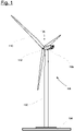
- FIG. 1 shows a schematic view of a wind turbine 100, which comprises a tower 102.
- the tower 102 is fixed to the ground by means of a foundation 104.
- a nacelle 106 is rotatably mounted.
- the nacelle 106 for example, comprises a generator which is coupled to a rotor 108 via a rotor shaft (not shown).
- the rotor 108 comprises one or more (wind turbine) rotor blades 110, which are arranged on a rotor hub 112.
- the rotor 108 is set in rotation by an air flow, for example wind. This rotational movement is transmitted to the generator via the rotor shaft and, if necessary, a gearbox.
- the generator converts the mechanical energy of the rotor 108 into electrical energy.
- FIG. 2 shows an exemplary wind turbine rotor blade 110.
- the rotor blade 110 has the shape of a conventional rotor blade and has a rotor blade root area 114 facing the rotor hub 112.
- the rotor blade root area 114 typically has an essentially circular cross-section.
- the rotor blade root area 114 is followed by a transition area 116 and a profile area 118 of rotor blade 110.
- the rotor blade 110 has a pressure side 122 and an opposite suction side 124 with respect to a longitudinal extension direction 120 (also main extension direction).
- the rotor blade 110 is essentially hollow inside.
- a rotor blade connection end 126 with a flange connection 128 is provided, by means of which the rotor blade 110 is mechanically connected to a pitch bearing or an extender.
- the rotor blade 110 comprises a division area 130 where a blade root-side rotor blade segment 132 (first rotor blade segment) and a blade tip-side rotor blade segment 134 (second rotor blade segment) are connected to each other.
- both segments 132, 134 each comprise a segment connection area 136, 138 (also named connection ends).
- the rotor blade 110 is thus a split rotor blade as described above.
- Each connection end 136, 138 has a multitude of sleeves or bushings 140, 142, which are arranged according to the profile (in circumferential direction) and comprise internal threads for the reception of screw bolts, also called bearing bolts or connecting bolts.
- first bushings 140 comprise left-hand threads (first internal threads) and the second bushings 142 right-hand threads (second internal threads) or vice versa.
- a connection end 136, 138 is realized for example as a flange insert, which is inserted as an insert into a production mould for the manufacture of the rotor blade 110.
- no flange insert is provided and the bushings are embedded and laminated directly into the rotor blade half shells.
- the bushings are steel sleeves, for example.
- connection of both rotor blade segments 132, 134 will be described in more detail using a single bolt connection as an example with the help of figure 3 , which shows a schematic sectional view in the division area 130 of the two connected rotor blade segments 132, 134.
- the first connection end 136 of the first rotor blade segment 132 comprises a multitude of first bushings 140 as described above.
- the second connection end 138 of the second rotor blade segment 134 comprises a number of second bushings 142.
- a connecting bolt 146 is screwed into each pair of aligned first and second bushings 140, 142. This bolt 146 connects the two connection ends 136, 138 and thus the two rotor blade segments 132, 134 mechanically.
- a pressure piece 144 is clamped between the two connection ends 136, 138 per bolt connection 148.
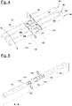
- Figure 4 shows three bolt connections 148 of a segmented wind turbine rotor blade 110 according to an embodiment of the invention.
- Figure 5 shows one such bolt connection 148 in an explosion view.
- first metal sheets 150 are clamped (also named first clamping sheets), after screwing the segments 132, 134 together via the bolts 146.
- the first metal sheets 150 are clamped between end faces 152 of the first bushings 140 at the first connection end 136 and first end faces 154 of the pressure pieces 144 as well as between second end faces 156 of the pressure pieces 144 and end faces 158 of the second bushings 142 of the second connection end 138.
- the first metal sheets 150 are arranged along the circumference 151 (indicated in figure 4 ) of the blade 110 on the suction and pressure sides 124, 122.
- the first metal sheets 150 are equal parts.
- Each first metal sheet 150 is electrically conductive and couples two pressure pieces 144 in an electrically conductive manner.
- each first metal sheets 150 comprises two openings 160 (recesses). Through the openings 160 the connection bolts 146 can be passed.
- the pressure pieces 144 correspondingly are electrically conductive, too, and formed by a respective metal for example.
- the first metal sheets 150 are designed and mounted between the segments 132, 134 and pressure pieces 144 such that no contact is established to the bolts 146.
- centering rings 162 also named support rings
- first metal sheets 150 are mounted to the bushings 140, 142 and protrude through the first metal sheets 150 in order to center them with respect to the bolts 146.
- each first metal sheet 150 at the first connection end 136 is arranged offset to a respective opposing first metal sheet 150 at the second connection end 138, with respect to the circumference 151 of the blade 110.
- one half of a first metal sheet 150 at the root-sided first connection end 136 is connected to one half of a metal sheet 150 at the tip-sided second connection end 138 via the pressure piece 144.
- Figure 7 shows that one first metal sheet 150, which is associated to the first connection end 136 or the first rotor blade segment 132 (root segment), is coupled to a first lightning conductor cable 164 in an electrically conductive manner.
- one first metal sheet 150 which is associated to the second connection end 138 or the second rotor blade segment 134 (tip segment), is coupled to a second lightning conductor cable 166 in an electrically conductive manner.
- the lightning conductor cables 164, 166 are part of a lightning protection system.
- first and second lightning conductor cables 164, 166 can be provided such that each segment 132, 134 has a lightning conductor cable 164 or 166 on both the suction and pressure side 124, 122.
- the first metal sheets 150 have one or more interfaces, e.g. eyelets (see also figures 11 to 13 and corresponding description below).
- a current path 168 is meander like in the division area 130 and runs from (a half of) one first metal sheet 150 at the first connection end 136 over a corresponding pressure piece 144 to (a half of) the opposing first metal sheet 150 at the second connection end 138.
- the current path 168 comprises several sections, i.e. a first segment path section 168a (lightning conductor), metal sheet path sections 168b, pressure piece path sections 168c and a second segment path section 168d (lightning conductor).
- first segment path section 168a lightning conductor
- metal sheet path sections 168b metal sheet path sections 168b
- pressure piece path sections 168c and a second segment path section 168d (lightning conductor).
- the metal sheet path sections 168b and the pressure piece path sections 168c establish the meander like current path.
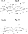
- Figures 9a and 9b show such a wind turbine rotor blade 110 at the division area 130 according to an embodiment of the invention.
- Figure 9a shows the first segment 132 and the first connection end 136
- figure 9b shows the second segment 134 and the second connection end 138.
- an odd number of bolt connections 148 (only two indicated with reference signs in figure 9a ) is provided.
- the first metal sheets 150 are arranged as described above such that at both the suction and pressure side 124, 122, a single, last bolt connection 148* (last first bushing 140*) facing the trailing edge 170 would remain free of a first metal sheet 150.
- a second metal sheet 174 is provided, which is similar to a first metal sheet 150 and designed to connect these last bolt connections 148* (i.e. the respective first bushings 140 and pressure pieces 144) in order to continue the meandering like arrangement from the suction side to the pressure side 124, 122 at the first segment 132.
- last bolt connections 148* (last second bushings 142*) remain free of a first metal sheet 150 at the second segment 134, however at the leading edge 172 (facing the leading edge 172).
- a third metal sheet 176 is provided, e.g. in the form of a disc.
- each bolt connection 148, 148* has a similar mechanical arrangement, too.
- Figures 10a and 10b show a slightly different embodiment of the invention compared to the example according to figure 9a and 9b .
- an even number of bolt connections 148 is provided at the pressure and the suction side 122, 124.
- first metal sheets 150 can be used and no single bolt connection 148 (i.e. second bushing 142) remains free of a first metal sheet 150.
- second bushing 142 At the first segment, at both ends of the suction and pressure side 124, 122 a single bolt connection 148* remains free with respect to the circumference 151.
- the single bolt connections 148* e.g. first bushings 140*
- the trailing edge 170 and at the leading edge 172 at the first segment 132 are conductively connected via a second metal sheet 174.
- each metal sheet 150, 174, 176 lies flat against the corresponding faces (e.g. end faces of the respective pressure pieces 144). Further, each metal sheet is a fine rolled sheet as described in the introductory part.
- the metal sheets 150, 174, 176 are not in direct electrically conductive contact with another metal sheet.
- each two adjacent metal sheets at one blade segment 132, 134 are not in direct contact with each other.
- no electrically conductive contact is established.
- With respect to the circumference 151 left and right ends of a metal sheet 150, 174, 176 essentially coincides with the outer ends of respective bushing or bushings 140, 142. In other words, with respect to the circumference 151 left and right ends of metal sheet 150, 174, 176 does not extend over an outer most end of a pressure piece 144.
- Figures 11 to 13 show different embodiments of a metal sheet 178 for the above described rotor blades 110 and bolt connections 148/148*, which allows the attachment of lightning conductor cables (e.g. discharge cables), receptors or aerodynamic cover elements.
- the above described features and functions with regard to a first, a second or a third metal sheet 150, 174, 176 similarly apply to the metal sheet 178.
- the following details are analogously applicable to a first, a second or a third metal sheet 150, 174, 176.
- the metal sheet 178 comprises one or more openings 160 as described above to be mounted over respective connecting bolts 146.
- the metal sheet 178 comprises one or more tabs 180 protruding from a main body 182.
- the main body 182 is defined as the part of the metal sheet 178 which extends between the bolt connections 148 along the circumference 151 and connects the pressure pieces 144 and bushings 140, 142.
- the tabs 180 are an integral part of the metal sheet 178 and can fully extend in the main extension area 184 of the metal sheet 178 or can have an at least partially bent section 186, e.g. at 90°.
- the tabs 180 comprise one or more interfaces 188 for attachment of other components.
- the interfaces 188 are eyelets in the shown embodiments.
Landscapes
- Engineering & Computer Science (AREA)
- Life Sciences & Earth Sciences (AREA)
- Sustainable Development (AREA)
- Sustainable Energy (AREA)
- Chemical & Material Sciences (AREA)
- Combustion & Propulsion (AREA)
- Mechanical Engineering (AREA)
- General Engineering & Computer Science (AREA)
- Wind Motors (AREA)
Abstract
Description
- The invention concerns a wind turbine rotor blade with at least two rotor blade segments and a metal sheet for a wind turbine blade.
- Wind turbines with wind turbine rotor blades are widely known from the state of the art and are used to convert wind energy into electrical energy. Wind turbines comprise a multitude of components which are connected to each other, for example by means of a flange connection. For example, in the area of a rotor blade root, the rotor blades comprise a rotor blade connection with a number of connecting means integrated into the laminate, via which the rotor blades are connected to a bearing ring of a so-called pitch bearing or to a component connected to the bearing ring, such as a so-called extender of the wind turbine, by means of fastening screws or fastening bolts. The connecting means can, for example, be designed as transverse bolts or bushings and be part of a flange insert for the rotor blade connection. Such a design is known from international application
WO 2015/124568 A1 . - The above described (flanged) connections are also used for connecting rotor blade segments which, arranged and joined together lengthwise, form an entire rotor blade. Such a rotor blade is called a split or segmented rotor blade. For example, connecting means are then located in the laminate of a respective connection end or dividing flange of the rotor blade segments. The rotor blade segments can be connected to each other by means of bolts either directly or via suitable intermediate pieces.
- Segmented rotor blades are preferred especially for transport reasons and are becoming increasingly important, especially due to the increasing overall length of rotor blades.
- A problem that arises with segmented rotor blades is that all systems and components of the blade are separated at the separation area. For example, there is the problem that a lightning protection system is completely separated at the segmentation area. But this segmentation area contains a large number of parallel electrical conductors (e.g. inserts, bolts, etc.), which are highly attractive for the impact of lightning, but cannot dissipate these currents, so there is a very high risk of sparking.
- Thus, one task underlying the present invention is to provide a concept for segmented rotor blades that enables a reliable lightning protection system, wherein the structural concept of the blade segmentation is not negatively affected. Further, the concept should allow the system to be installed without tools, with very little effort and under the required climatic conditions at the construction site. Furthermore, it is required that cross-sectional displacements at the segmentation area (expansions and compressions) should be tolerated and the lightning currents (tip and direct strikes) can be safely discharged to earth.
- According to a first aspect a wind turbine rotor blade is disclosed, which is formed by at least two rotor blade segments. Said segments are screwed together at respective connection ends by means of a plurality of connecting bolts. Sleeve-shaped pressure pieces are arranged between the rotor blade segments, each of which is mounted on a connecting bolt. A plurality of first metal sheets is provided, each first metal sheet being arranged between a respective connection end and several pressure pieces, so that an electrically conductive connection is formed between several pressure pieces by means of a respective first metal sheet. The first metal sheets, which are associated with the first connection end, are each arranged offset from the first metal sheets, which are associated with the second terminal end, with respect to the circumference of the rotor blade.
- For connecting the two rotor blade segments of a wind turbine rotor blade, these typically comprise a large number of corresponding connecting elements, such as bushings, at the connection ends to be connected. The connecting elements are used to create a large number of bolt connections between the two segments. The assembly is designed in such a way that the connecting bolts are first screwed into a connection end of one rotor blade segment, e.g. into the bushings. Then the first metal sheets and the sleeve-shaped pressure pieces are pushed onto the connecting bolts before the free ends of the connecting bolts are threaded into the corresponding connecting element of the other rotor blade segment and at least partially screwed in. Finally, the two rotor blade segments are bolted together, whereby the connection is firmly screw-bolted and pretensioned using an assembly tool. Thus, the pressure pieces are clamped between the rotor blade segments.
- Here and in the following, the explanations and features relating to the first metal sheets also apply analogously to other metal sheets described below.
- The inventive wind turbine rotor blade provides that the first metal sheets are arranged offset from the root segment to the tip segment. In other words, with respect to a longitudinal axis of the blade a first metal sheet next to the tip segment does not entirely overlap with a first metal sheet next to the root segment, but only partially. In further other, for example a first metal sheet at the tip segment connects a first group of pressure pieces, whereas an opposing first metal sheet at the root segment connects one or some (but not all) pressure pieces of the first group and at least one further pressure piece not belonging to the first group. This means that in each case a section of one first metal sheet at the tip segment is electrically connected via a respective pressure piece to a section of another first metal sheet at the root segment of the blade. Due to the described arrangement of first metal sheets arranged offset to each other at both sides of the pressure pieces along the circumference of the rotor blade, a current transmission due to a lightning strike runs in a meandering manner through the pressure pieces via the first metal sheets on both sides of the pressure pieces. In other words, the first metal sheets are arranged such that a meandering electrically conductive connection is established via the pressure pieces.
- For example, adjacent first metal sheets, which are associated with the first connection end, are spaced apart from each other. Adjacent first metal sheets, which are associated with the second connection end, are spaced apart from each other. This means that adjacent first metal sheets at the tip side or adjacent first metal sheets at the root side do not contact each other, i.e. in an electrically conductive manner. In other words, there is no direct contact between two adjacent first metal sheets. For example, none of the first metal sheets is in direct contact, i.e. touch, to any other first metal sheet.
- For example, with respect to the circumference left and right ends of a first metal sheet essentially coincides with the outer ends of respective connecting elements. In other words, with respect to the circumference left and right ends of a first metal sheet do not extend over an outer most surface of a pressure piece.
For example, the first metal sheets are arranged directly at the interface between the connection end and the pressure piece, e.g. at end faces of the connection end and the pressure piece, in particular at mating surfaces. The end faces do not have to be necessarily prepared or manipulated prior to installation of the first metal sheets. - The first metal sheets are arranged between each connection end of the two rotor blade segments and the pressure pieces along a circumference of the rotor blade. To connect them in an electrically conductive manner, each first metal sheet is arranged along the circumference of the rotor blade between a corresponding connection end of the blade and several adjacent pressure pieces. The pressure pieces and metal sheets are designed to be metallically conductive. In particular, the first metal sheets are clamped in the assembled state between a connection end and the pressure pieces. Thus, the metal sheets could also be named clamping sheets. The first metal sheets could comprise a hole or opening for each bolt to be guided through such a hole, in order for several bolt connections, e.g. pressure pieces, to be coupled.
- Further, a greatest possible torque is typically applied in the area where the first metal sheets are arranged, so that in addition to a geometric fit, a mechanical connection can also be used very well.
- As a big advantage, the first metal sheets, for example, are of very small dimensions and/or connect only a few pressure pieces, such as four or three pressure pieces. Particularly preferably, the first metal sheets connect two pressure pieces each. In the latter case, for example, two first metal sheets are formed and arranged offset such that one half of each first metal sheet is arranged at a respective end of a pressure piece.
- As already indicated above, the first metal sheets enable a meandering current transmission that is easily calculable, verifiable and well controllable. This provides the following advantages:
- Compared to a continuous metal sheet extending over the entire circumference of the rotor blade or a rotor blade half shell, the disclosed solution saves material and mass.
- Compared to a continuous metal clamping sheet extending over the entire circumference of the rotor blade or a rotor blade half shell, which connects all inserts with each other and thus exemplarily has to have a large number of precise holes and also has to follow the curvature of the cross-section in the segmentation area, the metal sheets according to the invention do not require a large chain of tolerances in shape, contour and position. Rather, these (small) first metal sheets make special use of the fact that only one short or single closely toleranced distance between a few bolt connections (pressure pieces, e.g. two connections) has to fit and no, or only little, curvature is necessary. Thus, a high fitting accuracy over a theoretically infinite row of bolt connections, i.e. inserts, is the result.
- Compared to a continuous large metal clamping sheet extending over the entire circumference of the rotor blade or a rotor blade half shell and having wide measurements, the first metal sheets can be obtained in very accurate wall thicknesses (up to +/- 0.03mm for cold rolled precision steel strips with narrow width), in high material quality and with low manufacturing costs, at best only a 2D cut of small size is necessary.
- The first metal sheets, e.g. very small sheets only connecting two pressure pieces, can be produced in higher quantities, thus additionally favorably affecting their manufacture.
- Compared to a continuous large clamping sheet extending over the entire circumference of the rotor blade or a rotor blade half shell, the first metal sheets contribute to a small packing size and do not require large logistical or packing efforts to get to the construction site or to be handled on the construction site. Therefore, the first metal sheets contribute to a very user-friendly installation and could be handled by only one person.
- Compared to solutions that provide for mounting on other electrically conductive parts of the segmentation area and require additional fasteners for this purpose, these first metal sheets can be mounted without tools and with minimal manpower in all required climatic conditions.
- Positioning of the first metal sheets in relation to a solution that would be attached to the other electrically conductive parts of the connecting means (e.g. clamps on the pressure pieces) takes place nearly automatically, is highly time-saving and precise, and is also free of additional connecting means and thus the influence of errors.
- Due to the offset, e.g. paired, arrangement of the first metal sheets, a deformation of the segmentation cross-section can occur without any major interaction between a first metal sheet and the blade cross-section, since the less rigid area between the first metal sheets acts like a joint.
- The pressure piece is designed as a sleeve, i.e. the pressure piece comprises a continuous bore/opening along a main direction of extension, i.e. a longitudinal axis. The pressure piece is designed as a clamping sleeve, for example.
- A connecting bolt, for example, is a screw bolt. The connecting bolt is, for example, designed as an expansion shaft bolt (with corresponding external threads).
- The connecting elements mentioned, such as the bushings or inserts, are, for example, elements laminated into the connection ends of the blade segments.
- According to an embodiment the first (and the further to be described) metal sheets are equal parts. This means that identical parts for both sides of the pressure pieces are used. This contributes to a cheaper, simpler production and a simpler assembly.
- According to an embodiment a second metal sheet is provided which electrically conductively connects pressure pieces facing the leading edge and/or the trailing edge. In particular, two pressure pieces, one at the suction side and one at the pressure side, each being arranged closest to the leading edge, are coupled by the second metal sheet. Similarly, pressure pieces at the trailing edge can be connected by a second metal plate. In particular, for the connection of the shell halves within a blade segment, a modified metal sheet, namely the second metal sheet, is provided at least at the trailing edge due to the small insert distance between the pressure pieces against the risk of sparking. Advantageously additionally at the leading edge the second metal sheet enables a so-called potential equalization. The second metal sheet, for example, has a different length than the first metal sheet. The second metal sheet, for example, has a further fastening possibility for receptors or aerodynamic cover elements (see below).
- According to an embodiment a third metal sheet is provided, which is arranged between a connection end and only one pressure piece, in particular in the case of a pressure piece being adjacent to the leading edge or the trailing edge. For example, the respective pressure piece is arranged closest to the leading edge or trailing edge at the suction side or the pressure side of the blade.
- Depending on the design of the first metal sheets and amount of bolt connections it may be the case that one bolt connection might remain without a metal sheet. In this case, the third metal sheet could be arranged between a connection end and only a single pressure piece. For example in the case of first metal sheets extending over two pressure pieces, the arrangement of first metal sheets might leave at least one insert per connection end in the case of an odd number of bolt connections (or pressure pieces respectively). For example, the third metal sheet could be a modified first metal sheet, e.g. in the form of a disc.
- It is noted that in embodiments, none of the second and/or third metal sheets are in direct contact or touch to each other or with any first metal sheet.
- According to an embodiment, one or more of the above-mentioned metal sheets, which are associated with the first rotor blade segment, are electrically conductively connected to a lightning conductor of the first rotor blade segment, and/or one or more of the above-mentioned metal sheets, which are associated with the second rotor blade segment, are electrically conductively connected to a lightning conductor of the second rotor blade segment. For example, for each segment a metal sheet on the suction side and a metal sheet on the pressure side are connected to a lightning conductor, e.g. lightning conductor cable. Thus, two connections to lightning conductors are established for each rotor blade segment.
- According to an embodiment, one or more of the above-mentioned metal sheets have an interface or means for attaching a further component, in particular a receptor or an aerodynamic cover. For example, a lightning receptor, which is connected to the lightning protection system, is coupled to one or more metal sheets, which is very advantageous at least in the leading edge area.
- According to an embodiment, the first metal sheets are formed to connect two adjacent pressure pieces in an electrically conductive manner. The functions and advantages described above are achieved in particular by the such first metal sheets.
- According to an embodiment, any or all of the above-mentioned metal sheets lie flat against the corresponding end faces of the connection ends and pressure pieces. Thus a very reliable and safe mechanical and electrically conductive connection is achieved.
- According to an embodiment, any or all of the above-mentioned metal sheets have one or more recesses through which the connecting bolts are guided accordingly. Depending on the number of pressure pieces to be connected, each metal sheet has corresponding recesses or holes. Thus, a very easy mounting and installation of metal sheets is enabled.
- According to an embodiment, any or all of the above-mentioned metal sheets are free of contact with the respective connecting bolts. Thus, any impact on the connecting bolts, either mechanically or electrically, can be avoided.
- According to an embodiment, any or all of the above-mentioned metal sheets are centered with respect to the respective connecting bolts by means of one or more centering rings arranged at the connection ends. Thus, a reliable, easy and safe installation of the metal sheets is possible. For example, the centering ring has one or more protrusions which engage an opening of a metal sheet to center the sheet with respect to the respective connecting bolt, which is guided through the metal sheet and the centering ring.
- According to an embodiment, any or all of the above-mentioned metal sheets are fine rolled sheets. In particular, a wall thickness of a sheet is approximately up to a maximum of 5mm sheet thickness. Such metal sheets can be produced with a very small tolerance, e.g. 0.03 mm to 0.05 mm.
- A further aspect is related to a metal sheet for a wind turbine rotor blade according to any of the embodiments described above. The metal sheet is designed to be arranged between a respective connection end and several pressure pieces of the wind turbine rotor blade, so that an electrically conductive connection is formed between the one or more pressure pieces by means of the metal sheet. In particular, the metal sheet is designed such that a connecting bolt can be passed through the metal piece.
- The metal sheet essentially enables the above-mentioned advantages and functions. The above described features analogously apply to the metal sheet of the further aspect. The metal sheet can be a first, second or third metal sheet.
- According to an embodiment, the metal sheet comprises one or more tabs for attaching a further component, in particular the tabs comprising one or more eyelets for attaching the further component. The tabs can be flat, e.g. extending in the main extension area of the metal sheet, or be angled, e.g. at 90°. Such a design optimizes installation and connection of further components like a lightning receptor or the like.
- Further advantages, features and functions are given in the following exemplary embodiments of the invention, which are explained in connection with the figures. Identical, similar or similarly acting elements are provided with the same reference signs in the figures. Not necessarily all shown and describes elements are provided with reference signs for sake of clarity and visibility.
- In the figures:
-
Figure 1 shows a schematic view of a wind turbine, -
Figure 2 shows a schematic view of a split rotor blade with two rotor blade segments, -
Figure 3 shows a schematic sectional view of an exemplary bolt connection of the two rotor blade segments, -
Figures 4 to 8 show different views of bolt connections of a wind turbine rotor blade according to an embodiment, -
Figures 9 and 10 show sectional views of two different segmented wind turbine rotor blades according to embodiments of the invention, and -
Figures 11 to 13 show different embodiments of a first metal sheet according to embodiments of the invention. -
Figure 1 shows a schematic view of awind turbine 100, which comprises atower 102. Thetower 102 is fixed to the ground by means of afoundation 104. At one end of thetower 102 opposite to the ground anacelle 106 is rotatably mounted. Thenacelle 106, for example, comprises a generator which is coupled to arotor 108 via a rotor shaft (not shown). Therotor 108 comprises one or more (wind turbine)rotor blades 110, which are arranged on arotor hub 112. - During operation, the
rotor 108 is set in rotation by an air flow, for example wind. This rotational movement is transmitted to the generator via the rotor shaft and, if necessary, a gearbox. The generator converts the mechanical energy of therotor 108 into electrical energy. -
Figure 2 shows an exemplary windturbine rotor blade 110. Therotor blade 110 has the shape of a conventional rotor blade and has a rotorblade root area 114 facing therotor hub 112. The rotorblade root area 114 typically has an essentially circular cross-section. The rotorblade root area 114 is followed by atransition area 116 and aprofile area 118 ofrotor blade 110. Therotor blade 110 has apressure side 122 and anopposite suction side 124 with respect to a longitudinal extension direction 120 (also main extension direction). Therotor blade 110 is essentially hollow inside. - In the rotor blade root area 114 a rotor
blade connection end 126 with aflange connection 128 is provided, by means of which therotor blade 110 is mechanically connected to a pitch bearing or an extender. - The
rotor blade 110 comprises adivision area 130 where a blade root-side rotor blade segment 132 (first rotor blade segment) and a blade tip-side rotor blade segment 134 (second rotor blade segment) are connected to each other. For this purpose, bothsegments segment connection area 136, 138 (also named connection ends). Therotor blade 110 is thus a split rotor blade as described above. Eachconnection end bushings first bushings 140 comprise left-hand threads (first internal threads) and thesecond bushings 142 right-hand threads (second internal threads) or vice versa. Aconnection end rotor blade 110. However, it is also conceivable that no flange insert is provided and the bushings are embedded and laminated directly into the rotor blade half shells. The bushings are steel sleeves, for example. - The connection of both
rotor blade segments figure 3 , which shows a schematic sectional view in thedivision area 130 of the two connectedrotor blade segments first connection end 136 of the firstrotor blade segment 132 comprises a multitude offirst bushings 140 as described above. Thesecond connection end 138 of the secondrotor blade segment 134 comprises a number ofsecond bushings 142. A connectingbolt 146 is screwed into each pair of aligned first andsecond bushings bolt 146 connects the two connection ends 136, 138 and thus the tworotor blade segments pressure piece 144 is clamped between the two connection ends 136, 138 perbolt connection 148. -
Figure 4 shows threebolt connections 148 of a segmented windturbine rotor blade 110 according to an embodiment of the invention.Figure 5 shows onesuch bolt connection 148 in an explosion view. Different to the embodiment offigure 3 , between eachconnection end blade 110 and thepressure pieces 144first metal sheets 150 are clamped (also named first clamping sheets), after screwing thesegments bolts 146. In particular, thefirst metal sheets 150 are clamped between end faces 152 of thefirst bushings 140 at thefirst connection end 136 and first end faces 154 of thepressure pieces 144 as well as between second end faces 156 of thepressure pieces 144 and end faces 158 of thesecond bushings 142 of thesecond connection end 138. - The
first metal sheets 150 are arranged along the circumference 151 (indicated infigure 4 ) of theblade 110 on the suction andpressure sides first metal sheets 150 are equal parts. Eachfirst metal sheet 150 is electrically conductive and couples twopressure pieces 144 in an electrically conductive manner. In the shown embodiment, eachfirst metal sheets 150 comprises two openings 160 (recesses). Through theopenings 160 theconnection bolts 146 can be passed. Thepressure pieces 144 correspondingly are electrically conductive, too, and formed by a respective metal for example. Thefirst metal sheets 150 are designed and mounted between thesegments pressure pieces 144 such that no contact is established to thebolts 146. This can be seen infigures 6a, 6b showing a sectional view A-A and a detailed view Z. In order to ensure a very easy and reliable installation, optional centering rings 162 (also named support rings) are mounted to thebushings first metal sheets 150 in order to center them with respect to thebolts 146. - As can be seen in the figures (see
figures 4, 5 ,7, 8 ), eachfirst metal sheet 150 at thefirst connection end 136 is arranged offset to a respective opposingfirst metal sheet 150 at thesecond connection end 138, with respect to thecircumference 151 of theblade 110. Thus, in the shown embodiment one half of afirst metal sheet 150 at the root-sidedfirst connection end 136 is connected to one half of ametal sheet 150 at the tip-sidedsecond connection end 138 via thepressure piece 144. -
Figure 7 shows that onefirst metal sheet 150, which is associated to thefirst connection end 136 or the first rotor blade segment 132 (root segment), is coupled to a firstlightning conductor cable 164 in an electrically conductive manner. Similarly, onefirst metal sheet 150, which is associated to thesecond connection end 138 or the second rotor blade segment 134 (tip segment), is coupled to a secondlightning conductor cable 166 in an electrically conductive manner. Thelightning conductor cables - In the shown example, the
bolt connections 148 are arranged at thesuction side 124 of theblade 110. On thepressure side 124, a similar installation is provided. Thus, further first and secondlightning conductor cables segment lightning conductor cable pressure side - For the connection to the
lightning conductor cables first metal sheets 150 have one or more interfaces, e.g. eyelets (see alsofigures 11 to 13 and corresponding description below). - As shown in
Figure 8 the above described design and arrangement offirst metal sheets 150 enables a meander like electrically conductive connection for the lightning protection system. In other words, a current path 168 is meander like in thedivision area 130 and runs from (a half of) onefirst metal sheet 150 at thefirst connection end 136 over acorresponding pressure piece 144 to (a half of) the opposingfirst metal sheet 150 at thesecond connection end 138. The current path 168 comprises several sections, i.e. a firstsegment path section 168a (lightning conductor), metalsheet path sections 168b, pressurepiece path sections 168c and a secondsegment path section 168d (lightning conductor). In particular the metalsheet path sections 168b and the pressurepiece path sections 168c establish the meander like current path. - Depending on the amount of
pressure pieces 144 to be connected by onefirst metal sheet 150 and depending on the amount ofbolt connections 148 to be established, different situations can occur, as exemplarily shown infigures 9a to 10b . In particular, single bolt connections 148 (and thusrespective pressure pieces 144 andbushings 140, 142) might remain free offirst metal sheets 150 at the ends on the suction andpressure side circumference 151 of theblade 110. -
Figures 9a and 9b show such a windturbine rotor blade 110 at thedivision area 130 according to an embodiment of the invention.Figure 9a shows thefirst segment 132 and thefirst connection end 136, whereasfigure 9b shows thesecond segment 134 and thesecond connection end 138. At both the suction andpressure side figure 9a ) is provided. At thefirst segment 132 thefirst metal sheets 150 are arranged as described above such that at both the suction andpressure side last bolt connection 148* (lastfirst bushing 140*) facing the trailingedge 170 would remain free of afirst metal sheet 150. In this case, asecond metal sheet 174 is provided, which is similar to afirst metal sheet 150 and designed to connect theselast bolt connections 148* (i.e. the respectivefirst bushings 140 and pressure pieces 144) in order to continue the meandering like arrangement from the suction side to thepressure side first segment 132. - Correspondingly, due to the odd number of
bolt connections 148,last bolt connections 148* (lastsecond bushings 142*) remain free of afirst metal sheet 150 at thesecond segment 134, however at the leading edge 172 (facing the leading edge 172). At theleading edge 172, no connection from the pressure to thesuction side last bolt connection 148* athird metal sheet 176 is provided, e.g. in the form of a disc. - Thus, the meandering like electrically conductive connection from the pressure to the
suction side second segment pressure piece 144 and the connection ends 136, 138 a metal sheet (first, second and third) is provided. This ensures that eachbolt connection -
Figures 10a and 10b show a slightly different embodiment of the invention compared to the example according tofigure 9a and 9b . Here, an even number ofbolt connections 148 is provided at the pressure and thesuction side second segment 134 onlyfirst metal sheets 150 can be used and no single bolt connection 148 (i.e. second bushing 142) remains free of afirst metal sheet 150. At the first segment, at both ends of the suction andpressure side 124, 122 asingle bolt connection 148* remains free with respect to thecircumference 151. In this case, thesingle bolt connections 148* (e.g.first bushings 140*) at the trailingedge 170 and at theleading edge 172 at thefirst segment 132 are conductively connected via asecond metal sheet 174. - It is noted that each
metal sheet - As can be seen in the figures, the
metal sheets blade segment circumference 151 left and right ends of ametal sheet bushings circumference 151 left and right ends ofmetal sheet pressure piece 144. -
Figures 11 to 13 show different embodiments of ametal sheet 178 for the above describedrotor blades 110 andbolt connections 148/148*, which allows the attachment of lightning conductor cables (e.g. discharge cables), receptors or aerodynamic cover elements. The above described features and functions with regard to a first, a second or athird metal sheet metal sheet 178. The following details are analogously applicable to a first, a second or athird metal sheet - The
metal sheet 178 comprises one ormore openings 160 as described above to be mounted over respective connectingbolts 146. Themetal sheet 178 comprises one ormore tabs 180 protruding from amain body 182. Themain body 182 is defined as the part of themetal sheet 178 which extends between thebolt connections 148 along thecircumference 151 and connects thepressure pieces 144 andbushings tabs 180 are an integral part of themetal sheet 178 and can fully extend in themain extension area 184 of themetal sheet 178 or can have an at least partially bent section 186, e.g. at 90°. Thetabs 180 comprise one ormore interfaces 188 for attachment of other components. Theinterfaces 188 are eyelets in the shown embodiments. - The embodiments as described above enables the functions, effects and advantages as listed in the introductory part of this writing.
-
- 100
- wind turbine
- 102
- tower
- 104
- foundation
- 106
- nacelle
- 108
- rotor
- 110
- rotor blade
- 112
- rotor hub
- 114
- rotor blade root area
- 116
- transition area
- 118
- profile area
- 120
- longitudinal extension direction
- 122
- pressure side
- 124
- suction side
- 126
- rotor blade connection end
- 128
- flange connection
- 130
- division area
- 132
- first rotor blade segment
- 134
- second rotor blade segment
- 136
- first connection end (root side)
- 138
- second connection end (tip side)
- 140/140*
- first bushing
- 142/142*
- second bushing
- 144
- pressure piece
- 146
- connection bolt
- 148/148*
- bolt connection
- 150
- first metal sheet
- 151
- circumference
- 152
- end face of first bushing/first connection end
- 154
- first end face of pressure piece
- 156
- second end face of pressure piece
- 158
- end face of second bushing/second connection end
- 160
- opening
- 162
- centering ring
- 164
- first lightning conductor
- 166
- second lightning conductor
- 168
- current path
- 168a
- first segment path
- 168b
- metal sheet path section
- 168c
- pressure piece path section
- 168d
- second segment path section
- 170
- trailing edge
- 172
- leading edge
- 174
- second metal sheet
- 176
- third metal sheet
- 178
- metal sheet
- 180
- tab
- 182
- main body
- 184
- main extension area
- 186
- bent section
- 188
- interface
Claims (15)
- Wind turbine rotor blade (110), which is formed by at least two rotor blade segments (132, 134), whereinsaid segments (132, 134) are screwed together at respective connection ends (136, 138) by means of a plurality of connecting bolts (146),sleeve-shaped pressure pieces (144) are arranged between the rotor blade segments (132, 134), each of which is mounted on a connecting bolt (146),a plurality of first metal sheets (150) is provided, each first metal sheet (150) being arranged between a respective connection end (136, 138) and several pressure pieces (144), so that an electrically conductive connection is formed between adjacent pressure pieces (144) by means of a first metal sheet (150), andthe first metal sheets (150), which are associated with the first connection end (136), are each arranged along the circumference (151) of the rotor blade (110) offset from the first metal sheets (150), which are associated with the second connection end (138).
- Wind turbine rotor blade (110) according to claim 1, wherein adjacent first metal sheets (151) are spaced apart from each other.
- Wind turbine rotor blade (110) according to claim 1 or 2, wherein the first metal sheets (150) are equal parts.
- Wind turbine rotor blade (110) according to any of the preceding claims, wherein a second metal sheet (174) is provided which electrically conductively connects pressure pieces (144) facing the leading edge (172) and/or the trailing edge (170).
- Wind turbine rotor blade (110) according to any of the preceding claims, wherein a third metal sheet (176) is provided, which is arranged between a respective connection end (136, 138) and only one pressure piece (144), in particular in the case of a pressure piece (144) facing the leading edge (172) or the trailing edge (170).
- Wind turbine rotor blade (110) according to any of the preceding claims, wherein one or more of the above-mentioned metal sheets (150, 174, 176), which are associated with the first rotor blade segment (132), are electrically conductively connected to a lightning conductor (164) of the first rotor blade segment (132), and/or one or more of the above-mentioned metal sheets (150, 174, 176), which are associated with the second rotor blade segment (134), are electrically conductively connected to a lightning conductor (166) of the second rotor blade segment (134).
- Wind turbine rotor blade (110) according to any of the preceding claims, wherein one or more of the above-mentioned metal sheets (150, 174, 176) have an interface (188) or means for attaching a further component, in particular a receptor or an aerodynamic cover.
- Wind turbine rotor blade (110) according to any of the preceding claims, wherein the first metal sheets (150) are formed to connect two pressure pieces (144) in an electrically conductive manner.
- Wind turbine rotor blade (110) according to any of the preceding claims, wherein any or all of the above-mentioned metal sheets (150, 174, 176) are clamped, in particular between opposing end faces (152 to 158) designed as mating surfaces.
- Wind turbine rotor blade (110) according to any of the preceding claims, wherein any or all of the metal sheets (150, 174, 176) lie flat against the corresponding end faces (152 to 158) of the connection ends (136, 138) and pressure pieces (144).
- Wind turbine rotor blade (110) according to any of the preceding claims, wherein any or all of the above mentioned metal sheets (150, 174, 176) have several recesses (160) through which the connecting bolts (146) are guided accordingly.
- Wind turbine rotor blade (110) according to any of the preceding claims, wherein any or all of the above mentioned metal sheets (150, 174, 176) being free of contact with the respective connecting bolts (146).
- Wind turbine rotor blade (110) according to any of the preceding claims, wherein any or all of the above mentioned metal sheets (150, 174, 176) are centered with respect to the respective connecting bolts (146) by means of one or more centering rings (162) arranged at the connection ends (136, 138) .
- Metal sheet (150, 174, 176, 178) for a wind turbine rotor blade (110) according to any of the preceding claims, the metal sheet (178) being designed to be arranged between a respective connection end (136, 138) and two or more pressure pieces (144) of the wind turbine rotor blade (110), so that an electrically conductive connection is formed between the several pressure pieces (144) by means of the metal sheet (178) .
- Metal sheet (150, 174, 176, 178) according to claim 13, comprising one or more tabs (180) for attaching a further component, in particular the tabs (180) comprising one or more eyelets for attaching the further component.
Priority Applications (8)
| Application Number | Priority Date | Filing Date | Title |
|---|---|---|---|
| EP21153710.5A EP4036400B1 (en) | 2021-01-27 | 2021-01-27 | Wind turbine rotor blade |
| PL21153710.5T PL4036400T3 (en) | 2021-01-27 | 2021-01-27 | Wind turbine rotor blade |
| DK21153710.5T DK4036400T3 (en) | 2021-01-27 | 2021-01-27 | WIND ENERGY PLANT ROTOR BLADE |
| ES21153710T ES2977311T3 (en) | 2021-01-27 | 2021-01-27 | Wind turbine rotor blade |
| PT211537105T PT4036400T (en) | 2021-01-27 | 2021-01-27 | Wind turbine rotor blade and metal sheet |
| US18/262,339 US12110871B2 (en) | 2021-01-27 | 2022-01-11 | Wind turbine rotor blade and metal sheet |
| PCT/EP2022/050385 WO2022161759A1 (en) | 2021-01-27 | 2022-01-11 | Wind turbine rotor blade and metal sheet |
| MX2023008725A MX2023008725A (en) | 2021-01-27 | 2022-01-11 | Wind turbine rotor blade and metal sheet. |
Applications Claiming Priority (1)
| Application Number | Priority Date | Filing Date | Title |
|---|---|---|---|
| EP21153710.5A EP4036400B1 (en) | 2021-01-27 | 2021-01-27 | Wind turbine rotor blade |
Publications (2)
| Publication Number | Publication Date |
|---|---|
| EP4036400A1 true EP4036400A1 (en) | 2022-08-03 |
| EP4036400B1 EP4036400B1 (en) | 2024-01-10 |
Family
ID=74285380
Family Applications (1)
| Application Number | Title | Priority Date | Filing Date |
|---|---|---|---|
| EP21153710.5A Active EP4036400B1 (en) | 2021-01-27 | 2021-01-27 | Wind turbine rotor blade |
Country Status (8)
| Country | Link |
|---|---|
| US (1) | US12110871B2 (en) |
| EP (1) | EP4036400B1 (en) |
| DK (1) | DK4036400T3 (en) |
| ES (1) | ES2977311T3 (en) |
| MX (1) | MX2023008725A (en) |
| PL (1) | PL4036400T3 (en) |
| PT (1) | PT4036400T (en) |
| WO (1) | WO2022161759A1 (en) |
Cited By (1)
| Publication number | Priority date | Publication date | Assignee | Title |
|---|---|---|---|---|
| WO2024132069A1 (en) * | 2022-12-22 | 2024-06-27 | Vestas Wind Systems A/S | Wind turbine blade root extender |
Families Citing this family (1)
| Publication number | Priority date | Publication date | Assignee | Title |
|---|---|---|---|---|
| DE102023100608A1 (en) * | 2023-01-12 | 2024-07-18 | Nordex Energy Se & Co. Kg | Insert for a wind turbine rotor blade and wind turbine rotor blade |
Citations (3)
| Publication number | Priority date | Publication date | Assignee | Title |
|---|---|---|---|---|
| US20080242129A1 (en) * | 2007-03-27 | 2008-10-02 | Matthew Robert Younce | Universal two-hole electrical bond washer |
| US20080240925A1 (en) * | 2007-01-23 | 2008-10-02 | Fuji Jukogyo Kabushiki Kaisha | Separable blade for wind turbine |
| WO2015124568A1 (en) | 2014-02-18 | 2015-08-27 | Lm Wp Patent Holding A/S | Wind turbine blade bushing system |
Family Cites Families (13)
| Publication number | Priority date | Publication date | Assignee | Title |
|---|---|---|---|---|
| DK176176B1 (en) * | 2004-11-24 | 2006-11-27 | Siemens Wind Power As | Method and connector for assembling a blade, preferably wind turbine blade, into sections |
| ES2337645B1 (en) * | 2007-09-14 | 2011-03-11 | GAMESA INNOVATION & TECHNOLOGY, S.L. | SENSORIZED SHOVEL UNION. |
| ES2373154B2 (en) | 2009-04-22 | 2012-06-07 | Gamesa Innovation & Technology, S.L. | RAY PROTECTION SYSTEM FOR SECTIONAL BLADES. |
| JP4939640B2 (en) * | 2010-10-22 | 2012-05-30 | 三菱重工業株式会社 | Wind turbine rotor |
| US20140178205A1 (en) * | 2012-12-21 | 2014-06-26 | General Electric Company | Joints for connecting blade segments of a wind turbine rotor blade |
| DE102016110551A1 (en) * | 2016-06-08 | 2017-12-14 | Wobben Properties Gmbh | Rotor for a wind turbine, rotor blade for a wind turbine, sleeve and method for mounting a rotor |
| US10830214B2 (en) | 2017-03-22 | 2020-11-10 | General Electric Company | Method for securing a lightning receptor cable within a segmented rotor blade |
| EP3784903A1 (en) | 2018-04-23 | 2021-03-03 | Vestas Wind Systems A/S | Wind turbine blade assembly |
| EP3581790B1 (en) * | 2018-06-14 | 2025-08-06 | Siemens Gamesa Renewable Energy A/S | Wind turbine rotor blade |
| EP4004363B1 (en) * | 2019-07-30 | 2026-04-15 | Vestas Wind Systems A/S | Connection for split wind turbine blade |
| ES3000786T3 (en) * | 2019-10-02 | 2025-03-03 | Nordex Energy Se & Co Kg | Wind turbine rotor blade and method for connecting two rotor blade segments |
| GB2602463A (en) * | 2020-12-28 | 2022-07-06 | Blade Dynamics Ltd | Protective cap for a leading edge of a wind turbine blade |
| ES2969936T3 (en) * | 2021-04-26 | 2024-05-23 | Nordex Energy Se & Co Kg | Wind turbine rotor blade and method |
-
2021
- 2021-01-27 ES ES21153710T patent/ES2977311T3/en active Active
- 2021-01-27 DK DK21153710.5T patent/DK4036400T3/en active
- 2021-01-27 PL PL21153710.5T patent/PL4036400T3/en unknown
- 2021-01-27 PT PT211537105T patent/PT4036400T/en unknown
- 2021-01-27 EP EP21153710.5A patent/EP4036400B1/en active Active
-
2022
- 2022-01-11 US US18/262,339 patent/US12110871B2/en active Active
- 2022-01-11 MX MX2023008725A patent/MX2023008725A/en unknown
- 2022-01-11 WO PCT/EP2022/050385 patent/WO2022161759A1/en not_active Ceased
Patent Citations (3)
| Publication number | Priority date | Publication date | Assignee | Title |
|---|---|---|---|---|
| US20080240925A1 (en) * | 2007-01-23 | 2008-10-02 | Fuji Jukogyo Kabushiki Kaisha | Separable blade for wind turbine |
| US20080242129A1 (en) * | 2007-03-27 | 2008-10-02 | Matthew Robert Younce | Universal two-hole electrical bond washer |
| WO2015124568A1 (en) | 2014-02-18 | 2015-08-27 | Lm Wp Patent Holding A/S | Wind turbine blade bushing system |
Cited By (1)
| Publication number | Priority date | Publication date | Assignee | Title |
|---|---|---|---|---|
| WO2024132069A1 (en) * | 2022-12-22 | 2024-06-27 | Vestas Wind Systems A/S | Wind turbine blade root extender |
Also Published As
| Publication number | Publication date |
|---|---|
| ES2977311T3 (en) | 2024-08-21 |
| PL4036400T3 (en) | 2024-05-13 |
| DK4036400T3 (en) | 2024-04-15 |
| US12110871B2 (en) | 2024-10-08 |
| WO2022161759A1 (en) | 2022-08-04 |
| MX2023008725A (en) | 2023-08-04 |
| US20240084784A1 (en) | 2024-03-14 |
| PT4036400T (en) | 2024-03-18 |
| EP4036400B1 (en) | 2024-01-10 |
Similar Documents
| Publication | Publication Date | Title |
|---|---|---|
| US8376713B2 (en) | Wind turbine rotor blade | |
| US12110871B2 (en) | Wind turbine rotor blade and metal sheet | |
| EP3581790A1 (en) | Wind turbine rotor blade | |
| EP2146402B1 (en) | Split slipring for maintainability | |
| US11795920B2 (en) | Lightning protection for a wind turbine blade | |
| EP4083414B1 (en) | Wind turbine rotor blade and method | |
| EP3728842B1 (en) | Wind turbine blade assembly | |
| EP4204678B1 (en) | Split wind turbine blade comprising a connection joint | |
| EP3821123B1 (en) | Improvements relating to wind turbine blades | |
| US11015570B2 (en) | Wind turbine rotor blade root insert with integrated flange member | |
| WO2021122275A1 (en) | Root assembly of a wind turbine blade for a wind turbine, wind turbine blade and wind turbine | |
| US11661922B2 (en) | Lightning receptor bracket | |
| EP3168457B1 (en) | Wind turbine with blades with a coning angle | |
| US12281640B2 (en) | Attachment to a sandwich structure element | |
| EP4158185A1 (en) | Wind blade having a lightning protection system | |
| EP3874143B1 (en) | Compliant structures for jointed rotor blades | |
| EP4506559A1 (en) | Blade segment, wind turbine and method for manufacturing a blade segment | |
| WO2021214150A1 (en) | Tip air receptor | |
| DK201570797A1 (en) | Improvements relating to lightning protection systems for wind turbine blades | |
| EP4506558A1 (en) | Method for joining two rotor blade segments of a wind turbine rotor blade as well as alignment pin | |
| EP4488504A1 (en) | Method for joining two rotor blade segments of a wind turbine rotor blade, bushing and wind turbine rotor blade | |
| EP4557588A1 (en) | Slip ring with insulated fan hub | |
| CN119325533A (en) | Rotor blade with lightning protection system, wind turbine and method of assembly | |
| WO2022053118A1 (en) | Wind turbine blade fairing | |
| BR112022010296B1 (en) | WIND TURBINE BLADE ROOT ASSEMBLY FOR A WIND TURBINE, WIND TURBINE BLADE AND WIND TURBINE |
Legal Events
| Date | Code | Title | Description |
|---|---|---|---|
| PUAI | Public reference made under article 153(3) epc to a published international application that has entered the european phase |
Free format text: ORIGINAL CODE: 0009012 |
|
| STAA | Information on the status of an ep patent application or granted ep patent |
Free format text: STATUS: THE APPLICATION HAS BEEN PUBLISHED |
|
| AK | Designated contracting states |
Kind code of ref document: A1 Designated state(s): AL AT BE BG CH CY CZ DE DK EE ES FI FR GB GR HR HU IE IS IT LI LT LU LV MC MK MT NL NO PL PT RO RS SE SI SK SM TR |
|
| STAA | Information on the status of an ep patent application or granted ep patent |
Free format text: STATUS: REQUEST FOR EXAMINATION WAS MADE |
|
| 17P | Request for examination filed |
Effective date: 20221206 |
|
| RBV | Designated contracting states (corrected) |
Designated state(s): AL AT BE BG CH CY CZ DE DK EE ES FI FR GB GR HR HU IE IS IT LI LT LU LV MC MK MT NL NO PL PT RO RS SE SI SK SM TR |
|
| GRAP | Despatch of communication of intention to grant a patent |
Free format text: ORIGINAL CODE: EPIDOSNIGR1 |
|
| STAA | Information on the status of an ep patent application or granted ep patent |
Free format text: STATUS: GRANT OF PATENT IS INTENDED |
|
| INTG | Intention to grant announced |
Effective date: 20230818 |
|
| GRAS | Grant fee paid |
Free format text: ORIGINAL CODE: EPIDOSNIGR3 |
|
| GRAA | (expected) grant |
Free format text: ORIGINAL CODE: 0009210 |
|
| STAA | Information on the status of an ep patent application or granted ep patent |
Free format text: STATUS: THE PATENT HAS BEEN GRANTED |
|
| AK | Designated contracting states |
Kind code of ref document: B1 Designated state(s): AL AT BE BG CH CY CZ DE DK EE ES FI FR GB GR HR HU IE IS IT LI LT LU LV MC MK MT NL NO PL PT RO RS SE SI SK SM TR |
|
| REG | Reference to a national code |
Ref country code: GB Ref legal event code: FG4D |
|
| REG | Reference to a national code |
Ref country code: CH Ref legal event code: EP |
|
| REG | Reference to a national code |
Ref country code: DE Ref legal event code: R096 Ref document number: 602021008407 Country of ref document: DE |
|
| REG | Reference to a national code |
Ref country code: IE Ref legal event code: FG4D |
|
| REG | Reference to a national code |
Ref country code: PT Ref legal event code: SC4A Ref document number: 4036400 Country of ref document: PT Date of ref document: 20240318 Kind code of ref document: T Free format text: AVAILABILITY OF NATIONAL TRANSLATION Effective date: 20240312 |
|
| REG | Reference to a national code |
Ref country code: DK Ref legal event code: T3 Effective date: 20240410 |
|
| REG | Reference to a national code |
Ref country code: LT Ref legal event code: MG9D |
|
| REG | Reference to a national code |
Ref country code: NL Ref legal event code: MP Effective date: 20240110 |
|
| REG | Reference to a national code |
Ref country code: AT Ref legal event code: MK05 Ref document number: 1649074 Country of ref document: AT Kind code of ref document: T Effective date: 20240110 |
|
| PG25 | Lapsed in a contracting state [announced via postgrant information from national office to epo] |
Ref country code: NL Free format text: LAPSE BECAUSE OF FAILURE TO SUBMIT A TRANSLATION OF THE DESCRIPTION OR TO PAY THE FEE WITHIN THE PRESCRIBED TIME-LIMIT Effective date: 20240110 |
|
| PG25 | Lapsed in a contracting state [announced via postgrant information from national office to epo] |
Ref country code: NL Free format text: LAPSE BECAUSE OF FAILURE TO SUBMIT A TRANSLATION OF THE DESCRIPTION OR TO PAY THE FEE WITHIN THE PRESCRIBED TIME-LIMIT Effective date: 20240110 |
|
| PG25 | Lapsed in a contracting state [announced via postgrant information from national office to epo] |
Ref country code: IS Free format text: LAPSE BECAUSE OF FAILURE TO SUBMIT A TRANSLATION OF THE DESCRIPTION OR TO PAY THE FEE WITHIN THE PRESCRIBED TIME-LIMIT Effective date: 20240510 |
|
| PG25 | Lapsed in a contracting state [announced via postgrant information from national office to epo] |
Ref country code: LT Free format text: LAPSE BECAUSE OF FAILURE TO SUBMIT A TRANSLATION OF THE DESCRIPTION OR TO PAY THE FEE WITHIN THE PRESCRIBED TIME-LIMIT Effective date: 20240110 |
|
| PG25 | Lapsed in a contracting state [announced via postgrant information from national office to epo] |
Ref country code: GR Free format text: LAPSE BECAUSE OF FAILURE TO SUBMIT A TRANSLATION OF THE DESCRIPTION OR TO PAY THE FEE WITHIN THE PRESCRIBED TIME-LIMIT Effective date: 20240411 |
|
| PG25 | Lapsed in a contracting state [announced via postgrant information from national office to epo] |
Ref country code: HR Free format text: LAPSE BECAUSE OF FAILURE TO SUBMIT A TRANSLATION OF THE DESCRIPTION OR TO PAY THE FEE WITHIN THE PRESCRIBED TIME-LIMIT Effective date: 20240110 Ref country code: RS Free format text: LAPSE BECAUSE OF FAILURE TO SUBMIT A TRANSLATION OF THE DESCRIPTION OR TO PAY THE FEE WITHIN THE PRESCRIBED TIME-LIMIT Effective date: 20240410 |
|
| PG25 | Lapsed in a contracting state [announced via postgrant information from national office to epo] |
Ref country code: AT Free format text: LAPSE BECAUSE OF FAILURE TO SUBMIT A TRANSLATION OF THE DESCRIPTION OR TO PAY THE FEE WITHIN THE PRESCRIBED TIME-LIMIT Effective date: 20240110 |
|
| PG25 | Lapsed in a contracting state [announced via postgrant information from national office to epo] |
Ref country code: RS Free format text: LAPSE BECAUSE OF FAILURE TO SUBMIT A TRANSLATION OF THE DESCRIPTION OR TO PAY THE FEE WITHIN THE PRESCRIBED TIME-LIMIT Effective date: 20240410 Ref country code: NO Free format text: LAPSE BECAUSE OF FAILURE TO SUBMIT A TRANSLATION OF THE DESCRIPTION OR TO PAY THE FEE WITHIN THE PRESCRIBED TIME-LIMIT Effective date: 20240410 Ref country code: LT Free format text: LAPSE BECAUSE OF FAILURE TO SUBMIT A TRANSLATION OF THE DESCRIPTION OR TO PAY THE FEE WITHIN THE PRESCRIBED TIME-LIMIT Effective date: 20240110 Ref country code: IS Free format text: LAPSE BECAUSE OF FAILURE TO SUBMIT A TRANSLATION OF THE DESCRIPTION OR TO PAY THE FEE WITHIN THE PRESCRIBED TIME-LIMIT Effective date: 20240510 Ref country code: HR Free format text: LAPSE BECAUSE OF FAILURE TO SUBMIT A TRANSLATION OF THE DESCRIPTION OR TO PAY THE FEE WITHIN THE PRESCRIBED TIME-LIMIT Effective date: 20240110 Ref country code: GR Free format text: LAPSE BECAUSE OF FAILURE TO SUBMIT A TRANSLATION OF THE DESCRIPTION OR TO PAY THE FEE WITHIN THE PRESCRIBED TIME-LIMIT Effective date: 20240411 Ref country code: BG Free format text: LAPSE BECAUSE OF FAILURE TO SUBMIT A TRANSLATION OF THE DESCRIPTION OR TO PAY THE FEE WITHIN THE PRESCRIBED TIME-LIMIT Effective date: 20240110 Ref country code: AT Free format text: LAPSE BECAUSE OF FAILURE TO SUBMIT A TRANSLATION OF THE DESCRIPTION OR TO PAY THE FEE WITHIN THE PRESCRIBED TIME-LIMIT Effective date: 20240110 |
|
| REG | Reference to a national code |
Ref country code: ES Ref legal event code: FG2A Ref document number: 2977311 Country of ref document: ES Kind code of ref document: T3 Effective date: 20240821 |
|
| PG25 | Lapsed in a contracting state [announced via postgrant information from national office to epo] |
Ref country code: SE Free format text: LAPSE BECAUSE OF FAILURE TO SUBMIT A TRANSLATION OF THE DESCRIPTION OR TO PAY THE FEE WITHIN THE PRESCRIBED TIME-LIMIT Effective date: 20240110 Ref country code: LV Free format text: LAPSE BECAUSE OF FAILURE TO SUBMIT A TRANSLATION OF THE DESCRIPTION OR TO PAY THE FEE WITHIN THE PRESCRIBED TIME-LIMIT Effective date: 20240110 |
|
| REG | Reference to a national code |
Ref country code: CH Ref legal event code: PL |
|
| PG25 | Lapsed in a contracting state [announced via postgrant information from national office to epo] |
Ref country code: LU Free format text: LAPSE BECAUSE OF NON-PAYMENT OF DUE FEES Effective date: 20240127 |
|
| PG25 | Lapsed in a contracting state [announced via postgrant information from national office to epo] |
Ref country code: LU Free format text: LAPSE BECAUSE OF NON-PAYMENT OF DUE FEES Effective date: 20240127 |
|
| REG | Reference to a national code |
Ref country code: DE Ref legal event code: R097 Ref document number: 602021008407 Country of ref document: DE |
|
| PG25 | Lapsed in a contracting state [announced via postgrant information from national office to epo] |
Ref country code: SM Free format text: LAPSE BECAUSE OF FAILURE TO SUBMIT A TRANSLATION OF THE DESCRIPTION OR TO PAY THE FEE WITHIN THE PRESCRIBED TIME-LIMIT Effective date: 20240110 |
|
| PG25 | Lapsed in a contracting state [announced via postgrant information from national office to epo] |
Ref country code: BE Free format text: LAPSE BECAUSE OF NON-PAYMENT OF DUE FEES Effective date: 20240131 |
|
| PG25 | Lapsed in a contracting state [announced via postgrant information from national office to epo] |
Ref country code: CH Free format text: LAPSE BECAUSE OF NON-PAYMENT OF DUE FEES Effective date: 20240131 |
|
| PG25 | Lapsed in a contracting state [announced via postgrant information from national office to epo] |
Ref country code: EE Free format text: LAPSE BECAUSE OF FAILURE TO SUBMIT A TRANSLATION OF THE DESCRIPTION OR TO PAY THE FEE WITHIN THE PRESCRIBED TIME-LIMIT Effective date: 20240110 Ref country code: CZ Free format text: LAPSE BECAUSE OF FAILURE TO SUBMIT A TRANSLATION OF THE DESCRIPTION OR TO PAY THE FEE WITHIN THE PRESCRIBED TIME-LIMIT Effective date: 20240110 |
|
| PG25 | Lapsed in a contracting state [announced via postgrant information from national office to epo] |
Ref country code: SK Free format text: LAPSE BECAUSE OF FAILURE TO SUBMIT A TRANSLATION OF THE DESCRIPTION OR TO PAY THE FEE WITHIN THE PRESCRIBED TIME-LIMIT Effective date: 20240110 |
|
| PG25 | Lapsed in a contracting state [announced via postgrant information from national office to epo] |
Ref country code: SM Free format text: LAPSE BECAUSE OF FAILURE TO SUBMIT A TRANSLATION OF THE DESCRIPTION OR TO PAY THE FEE WITHIN THE PRESCRIBED TIME-LIMIT Effective date: 20240110 Ref country code: SK Free format text: LAPSE BECAUSE OF FAILURE TO SUBMIT A TRANSLATION OF THE DESCRIPTION OR TO PAY THE FEE WITHIN THE PRESCRIBED TIME-LIMIT Effective date: 20240110 Ref country code: RO Free format text: LAPSE BECAUSE OF FAILURE TO SUBMIT A TRANSLATION OF THE DESCRIPTION OR TO PAY THE FEE WITHIN THE PRESCRIBED TIME-LIMIT Effective date: 20240110 Ref country code: EE Free format text: LAPSE BECAUSE OF FAILURE TO SUBMIT A TRANSLATION OF THE DESCRIPTION OR TO PAY THE FEE WITHIN THE PRESCRIBED TIME-LIMIT Effective date: 20240110 Ref country code: CZ Free format text: LAPSE BECAUSE OF FAILURE TO SUBMIT A TRANSLATION OF THE DESCRIPTION OR TO PAY THE FEE WITHIN THE PRESCRIBED TIME-LIMIT Effective date: 20240110 Ref country code: CH Free format text: LAPSE BECAUSE OF NON-PAYMENT OF DUE FEES Effective date: 20240131 Ref country code: BE Free format text: LAPSE BECAUSE OF NON-PAYMENT OF DUE FEES Effective date: 20240131 |
|
| REG | Reference to a national code |
Ref country code: BE Ref legal event code: MM Effective date: 20240131 |
|
| PG25 | Lapsed in a contracting state [announced via postgrant information from national office to epo] |
Ref country code: MC Free format text: LAPSE BECAUSE OF FAILURE TO SUBMIT A TRANSLATION OF THE DESCRIPTION OR TO PAY THE FEE WITHIN THE PRESCRIBED TIME-LIMIT Effective date: 20240110 |
|
| PLBE | No opposition filed within time limit |
Free format text: ORIGINAL CODE: 0009261 |
|
| STAA | Information on the status of an ep patent application or granted ep patent |
Free format text: STATUS: NO OPPOSITION FILED WITHIN TIME LIMIT |
|
| PG25 | Lapsed in a contracting state [announced via postgrant information from national office to epo] |
Ref country code: MC Free format text: LAPSE BECAUSE OF FAILURE TO SUBMIT A TRANSLATION OF THE DESCRIPTION OR TO PAY THE FEE WITHIN THE PRESCRIBED TIME-LIMIT Effective date: 20240110 |
|
| PG25 | Lapsed in a contracting state [announced via postgrant information from national office to epo] |
Ref country code: IT Free format text: LAPSE BECAUSE OF FAILURE TO SUBMIT A TRANSLATION OF THE DESCRIPTION OR TO PAY THE FEE WITHIN THE PRESCRIBED TIME-LIMIT Effective date: 20240110 |
|
| 26N | No opposition filed |
Effective date: 20241011 |
|
| PG25 | Lapsed in a contracting state [announced via postgrant information from national office to epo] |
Ref country code: IT Free format text: LAPSE BECAUSE OF FAILURE TO SUBMIT A TRANSLATION OF THE DESCRIPTION OR TO PAY THE FEE WITHIN THE PRESCRIBED TIME-LIMIT Effective date: 20240110 |
|
| PG25 | Lapsed in a contracting state [announced via postgrant information from national office to epo] |
Ref country code: IE Free format text: LAPSE BECAUSE OF NON-PAYMENT OF DUE FEES Effective date: 20240127 |
|
| PG25 | Lapsed in a contracting state [announced via postgrant information from national office to epo] |
Ref country code: IE Free format text: LAPSE BECAUSE OF NON-PAYMENT OF DUE FEES Effective date: 20240127 |
|
| PG25 | Lapsed in a contracting state [announced via postgrant information from national office to epo] |
Ref country code: SI Free format text: LAPSE BECAUSE OF FAILURE TO SUBMIT A TRANSLATION OF THE DESCRIPTION OR TO PAY THE FEE WITHIN THE PRESCRIBED TIME-LIMIT Effective date: 20240110 |
|
| PG25 | Lapsed in a contracting state [announced via postgrant information from national office to epo] |
Ref country code: CY Free format text: LAPSE BECAUSE OF FAILURE TO SUBMIT A TRANSLATION OF THE DESCRIPTION OR TO PAY THE FEE WITHIN THE PRESCRIBED TIME-LIMIT; INVALID AB INITIO Effective date: 20210127 |
|
| PG25 | Lapsed in a contracting state [announced via postgrant information from national office to epo] |
Ref country code: HU Free format text: LAPSE BECAUSE OF FAILURE TO SUBMIT A TRANSLATION OF THE DESCRIPTION OR TO PAY THE FEE WITHIN THE PRESCRIBED TIME-LIMIT; INVALID AB INITIO Effective date: 20210127 |
|
| PG25 | Lapsed in a contracting state [announced via postgrant information from national office to epo] |
Ref country code: FI Free format text: LAPSE BECAUSE OF FAILURE TO SUBMIT A TRANSLATION OF THE DESCRIPTION OR TO PAY THE FEE WITHIN THE PRESCRIBED TIME-LIMIT Effective date: 20240110 |
|
| PGFP | Annual fee paid to national office [announced via postgrant information from national office to epo] |
Ref country code: GB Payment date: 20260122 Year of fee payment: 6 |
|
| PGFP | Annual fee paid to national office [announced via postgrant information from national office to epo] |
Ref country code: ES Payment date: 20260217 Year of fee payment: 6 |
|
| PGFP | Annual fee paid to national office [announced via postgrant information from national office to epo] |
Ref country code: DK Payment date: 20260121 Year of fee payment: 6 Ref country code: DE Payment date: 20260120 Year of fee payment: 6 |
|
| PGFP | Annual fee paid to national office [announced via postgrant information from national office to epo] |
Ref country code: FR Payment date: 20260127 Year of fee payment: 6 |
|
| PGFP | Annual fee paid to national office [announced via postgrant information from national office to epo] |
Ref country code: TR Payment date: 20260123 Year of fee payment: 6 |
|
| PGFP | Annual fee paid to national office [announced via postgrant information from national office to epo] |
Ref country code: PT Payment date: 20260120 Year of fee payment: 6 |
|
| PGFP | Annual fee paid to national office [announced via postgrant information from national office to epo] |
Ref country code: PL Payment date: 20260116 Year of fee payment: 6 |