EP4036379B1 - Bearing housing of a gas turbine engine - Google Patents
Bearing housing of a gas turbine engine Download PDFInfo
- Publication number
- EP4036379B1 EP4036379B1 EP21215136.9A EP21215136A EP4036379B1 EP 4036379 B1 EP4036379 B1 EP 4036379B1 EP 21215136 A EP21215136 A EP 21215136A EP 4036379 B1 EP4036379 B1 EP 4036379B1
- Authority
- EP
- European Patent Office
- Prior art keywords
- oil
- bearing housing
- bearing
- manifold
- channel
- Prior art date
- Legal status (The legal status is an assumption and is not a legal conclusion. Google has not performed a legal analysis and makes no representation as to the accuracy of the status listed.)
- Active
Links
Images

Classifications
-
- F—MECHANICAL ENGINEERING; LIGHTING; HEATING; WEAPONS; BLASTING
- F16—ENGINEERING ELEMENTS AND UNITS; GENERAL MEASURES FOR PRODUCING AND MAINTAINING EFFECTIVE FUNCTIONING OF MACHINES OR INSTALLATIONS; THERMAL INSULATION IN GENERAL
- F16C—SHAFTS; FLEXIBLE SHAFTS; ELEMENTS OR CRANKSHAFT MECHANISMS; ROTARY BODIES OTHER THAN GEARING ELEMENTS; BEARINGS
- F16C35/00—Rigid support of bearing units; Housings, e.g. caps, covers
- F16C35/04—Rigid support of bearing units; Housings, e.g. caps, covers in the case of ball or roller bearings
- F16C35/042—Housings for rolling element bearings for rotary movement
-
- F—MECHANICAL ENGINEERING; LIGHTING; HEATING; WEAPONS; BLASTING
- F01—MACHINES OR ENGINES IN GENERAL; ENGINE PLANTS IN GENERAL; STEAM ENGINES
- F01D—NON-POSITIVE DISPLACEMENT MACHINES OR ENGINES, e.g. STEAM TURBINES
- F01D25/00—Component parts, details, or accessories, not provided for in, or of interest apart from, other groups
- F01D25/18—Lubricating arrangements
-
- F—MECHANICAL ENGINEERING; LIGHTING; HEATING; WEAPONS; BLASTING
- F01—MACHINES OR ENGINES IN GENERAL; ENGINE PLANTS IN GENERAL; STEAM ENGINES
- F01D—NON-POSITIVE DISPLACEMENT MACHINES OR ENGINES, e.g. STEAM TURBINES
- F01D25/00—Component parts, details, or accessories, not provided for in, or of interest apart from, other groups
- F01D25/16—Arrangement of bearings; Supporting or mounting bearings in casings
-
- F—MECHANICAL ENGINEERING; LIGHTING; HEATING; WEAPONS; BLASTING
- F01—MACHINES OR ENGINES IN GENERAL; ENGINE PLANTS IN GENERAL; STEAM ENGINES
- F01D—NON-POSITIVE DISPLACEMENT MACHINES OR ENGINES, e.g. STEAM TURBINES
- F01D25/00—Component parts, details, or accessories, not provided for in, or of interest apart from, other groups
- F01D25/18—Lubricating arrangements
- F01D25/183—Sealing means
- F01D25/186—Sealing means for sliding contact bearing
-
- F—MECHANICAL ENGINEERING; LIGHTING; HEATING; WEAPONS; BLASTING
- F01—MACHINES OR ENGINES IN GENERAL; ENGINE PLANTS IN GENERAL; STEAM ENGINES
- F01D—NON-POSITIVE DISPLACEMENT MACHINES OR ENGINES, e.g. STEAM TURBINES
- F01D25/00—Component parts, details, or accessories, not provided for in, or of interest apart from, other groups
- F01D25/18—Lubricating arrangements
- F01D25/20—Lubricating arrangements using lubrication pumps
-
- F—MECHANICAL ENGINEERING; LIGHTING; HEATING; WEAPONS; BLASTING
- F01—MACHINES OR ENGINES IN GENERAL; ENGINE PLANTS IN GENERAL; STEAM ENGINES
- F01D—NON-POSITIVE DISPLACEMENT MACHINES OR ENGINES, e.g. STEAM TURBINES
- F01D5/00—Blades; Blade-carrying members; Heating, heat-insulating, cooling or antivibration means on the blades or the members
- F01D5/02—Blade-carrying members, e.g. rotors
-
- F—MECHANICAL ENGINEERING; LIGHTING; HEATING; WEAPONS; BLASTING
- F16—ENGINEERING ELEMENTS AND UNITS; GENERAL MEASURES FOR PRODUCING AND MAINTAINING EFFECTIVE FUNCTIONING OF MACHINES OR INSTALLATIONS; THERMAL INSULATION IN GENERAL
- F16C—SHAFTS; FLEXIBLE SHAFTS; ELEMENTS OR CRANKSHAFT MECHANISMS; ROTARY BODIES OTHER THAN GEARING ELEMENTS; BEARINGS
- F16C33/00—Parts of bearings; Special methods for making bearings or parts thereof
- F16C33/30—Parts of ball or roller bearings
- F16C33/66—Special parts or details in view of lubrication
- F16C33/6637—Special parts or details in view of lubrication with liquid lubricant
- F16C33/6659—Details of supply of the liquid to the bearing, e.g. passages or nozzles
-
- F—MECHANICAL ENGINEERING; LIGHTING; HEATING; WEAPONS; BLASTING
- F05—INDEXING SCHEMES RELATING TO ENGINES OR PUMPS IN VARIOUS SUBCLASSES OF CLASSES F01-F04
- F05D—INDEXING SCHEME FOR ASPECTS RELATING TO NON-POSITIVE-DISPLACEMENT MACHINES OR ENGINES, GAS-TURBINES OR JET-PROPULSION PLANTS
- F05D2220/00—Application
- F05D2220/30—Application in turbines
- F05D2220/32—Application in turbines in gas turbines
-
- F—MECHANICAL ENGINEERING; LIGHTING; HEATING; WEAPONS; BLASTING
- F05—INDEXING SCHEMES RELATING TO ENGINES OR PUMPS IN VARIOUS SUBCLASSES OF CLASSES F01-F04
- F05D—INDEXING SCHEME FOR ASPECTS RELATING TO NON-POSITIVE-DISPLACEMENT MACHINES OR ENGINES, GAS-TURBINES OR JET-PROPULSION PLANTS
- F05D2230/00—Manufacture
- F05D2230/50—Building or constructing in particular ways
- F05D2230/53—Building or constructing in particular ways by integrally manufacturing a component, e.g. by milling from a billet or one piece construction
-
- F—MECHANICAL ENGINEERING; LIGHTING; HEATING; WEAPONS; BLASTING
- F05—INDEXING SCHEMES RELATING TO ENGINES OR PUMPS IN VARIOUS SUBCLASSES OF CLASSES F01-F04
- F05D—INDEXING SCHEME FOR ASPECTS RELATING TO NON-POSITIVE-DISPLACEMENT MACHINES OR ENGINES, GAS-TURBINES OR JET-PROPULSION PLANTS
- F05D2240/00—Components
- F05D2240/50—Bearings
-
- F—MECHANICAL ENGINEERING; LIGHTING; HEATING; WEAPONS; BLASTING
- F05—INDEXING SCHEMES RELATING TO ENGINES OR PUMPS IN VARIOUS SUBCLASSES OF CLASSES F01-F04
- F05D—INDEXING SCHEME FOR ASPECTS RELATING TO NON-POSITIVE-DISPLACEMENT MACHINES OR ENGINES, GAS-TURBINES OR JET-PROPULSION PLANTS
- F05D2260/00—Function
- F05D2260/98—Lubrication
-
- F—MECHANICAL ENGINEERING; LIGHTING; HEATING; WEAPONS; BLASTING
- F16—ENGINEERING ELEMENTS AND UNITS; GENERAL MEASURES FOR PRODUCING AND MAINTAINING EFFECTIVE FUNCTIONING OF MACHINES OR INSTALLATIONS; THERMAL INSULATION IN GENERAL
- F16C—SHAFTS; FLEXIBLE SHAFTS; ELEMENTS OR CRANKSHAFT MECHANISMS; ROTARY BODIES OTHER THAN GEARING ELEMENTS; BEARINGS
- F16C2360/00—Engines or pumps
- F16C2360/23—Gas turbine engines
Definitions
- the disclosure relates generally to gas turbine engines and, more particularly, the invention relates to bearing housings for gas turbine engines.
- Oil is delivered to various locations in gas turbine engines for cooling and lubricating purposes.
- a bearing housing may include an oil manifold that is bolted, braced or otherwise mounted within the bearing housing.
- This oil manifold delivers oil to the bearing housed within the bearing housing and to the main engine shaft via one or more oil jets.
- Such typical add-on oil manifolds are often complicated to install and/or repair, offer little flexibility in terms of optimizing the placement of the oil jets, and could potentially interfere with rotating components such as the engine shaft.
- add-on manifolds typically require their own complex sealing arrangements to connect to the engine's main oil supply to avoid temperature-related degradation.
- US 5301957 A discloses a prior art bearing housing according to the preamble of claim 1.
- bearing housing as set forth in claim 1.
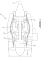
- FIG. 1 illustrates a gas turbine engine 10 of a type preferably provided for use in subsonic flight, generally comprising in serial flow communication a fan 12 through which ambient air is propelled, a compressor 14 for pressurizing the air, a combustor 16 in which the compressed air is mixed with fuel and ignited for generating an annular stream of hot combustion gases, and a turbine section 18 for extracting energy from the combustion gases.
- a shaft 20 interconnects the fan 12, the compressor 14 and the turbine 18.
- pressurized air provided by the compressor 14 through a diffuser 22 enters the combustor 16 for combustion.
- FIG. 1 shows gas turbine engine 10 to be a turbofan gas turbine engine, it is understood that the present disclosure is applicable to other types of gas turbine engines as well.
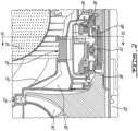
- FIGS. 2 and 3 show an enhanced view of the engine 10 proximate the combustor 16 and diffuser 22.
- a compressor 14 as in FIG. 1 which may include multiple axial stage rotors, is followed by a centrifugal impeller 24 having a coverplate 26.
- the compressor 14 supplies pressurized air to the combustor 16, the hot gases from which drive a turbine 18 as in FIG. 1 .
- a baffle 28 mounted downstream of the impeller 24 may reduce the velocity of the swirling air leaving the impeller 24.
- a bearing housing 30 houses a bearing 32 which rotationally supports rotors such as the compressor 14 and turbine 18 on the shaft 20.
- the bearing 32 is a roller bearing, although other bearings such as a ball bearing may be contemplated as well.
- the baffle 28 may be mounted to the bearing housing 30 as shown, although other arrangements may be contemplated as well.
- the bearing 32, housed within an interior chamber of the bearing housing 30, and the shaft 20 are lubricated and/or cooled with oil distributed by an oil manifold 34 integrated into the bearing housing 30.
- integral it is understood that the bearing housing 30 and the oil manifold 34 are machined or otherwise formed as a single, unitary or monolithic piece. Various machining processes may be contemplated, as will be discussed in further detail below.
- a front carbon seal 36 as well as a rear carbon seal 38 may be mounted within the bearing housing 30 to ensure that oil is sealed within the bearing housing 30.
- the front carbon seal 36 which may be a controlled-gap seal, may be pressurized, for instance via air from the impeller 24, to prevent oil distributed by the oil manifold 34 from leaking out of the bearing housing 30.
- Other seals may be contemplated as well.
- oil may be distributed by the oil manifold via an oil scoop 40 to lubricate and/or cool the shaft 20 and the bearing 32.
- the oil scoop 40 is disposed about the shaft 20 downstream of the bearing 32 and is radially aligned with the oil manifold 34.
- the bearing housing 30 includes an oil inlet 42 and an oil outlet 44.
- Oil may be delivered to the oil inlet 42 via an oil supply tube 46 or other like fluid delivery system.
- the oil may be provided from the engine's primary oil source, although other oil sources within the engine may be contemplated as well.
- Oil may be drained from the bearing housing 30, for instance after lubricating and/or cooling the bearing 32 and shaft 20, via the oil outlet 44. The drained oil may then be circulated back to the main oil supply or delivered to another location in the engine 10.
- an air inlet 48 supplies air to the bearing housing 30, for instance for various cooling or sealing purposes.
- the positioning of the oil inlet 42, oil outlet 44 and air inlet 48 about the bearing housing 30 may vary.
- the oil outlet 44 is positioned at the circumferential bottom of the bearing housing 30, while the oil inlet 42 and air inlet 48 are each positioned approximately sixty degrees apart from the oil outlet 44.
- Other positions may be contemplated as well.
- the oil inlet 42 may be positioned closer to one of the oil outlet 44 or air inlet 48.
- the delivery of oil via the oil manifold 34 may be optimized regardless of the positioning of the oil inlet 42 within the bearing housing.
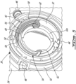
- the bearing housing 30 has an annular body extending around the axis 11 with an outer wall 50 and an inner wall 52.
- the bearing housing 30 further includes a bearing seat 32a with which the outer race of the bearing 32 is engaged.
- a plurality of webbed cutouts or windows 54 may be present in the annular body of the bearing housing 30, for instance to introduce required bearing support flexibility or to reduce weight.
- the presence of such webbed cutouts or windows 54 may allow additional airflow through the body of the bearing housing 30 for various engine needs.
- the integrated oil manifold 34 protrudes from the inner wall 52 and generally follows the circular shape of the inner wall 52. In the shown case, a plurality of gaps or cutouts 56 are formed between connecting ribs 58. These integrated ribs 58 are formed between the oil manifold 34 and the inner wall 52. These gaps or cutouts 56 may contribute to a lower overall engine weight. In other cases, the oil manifold 34 may be completely flush with the inner wall 52.
- the integrated oil manifold 34 includes an inner oil channel 60 which receives oil via the oil inlet 42.
- the inner oil channel 60 is defined in the annular body of the bearing housing 30 and extends in the circumferential direction along an arc of circle around the axis 11.
- the inner oil channel 60 directs the oil to one or more oil jets 62 which direct the oil to the bearing 32, the shaft 20, and/or other internal components for lubrication and/or cooling purposes.
- the oil manifold 34 includes two oil jets 62 disposed at opposed circumferential ends of the oil channel 60.
- the interior oil channel 60 extends radially inward towards each of the two oil jets 62 respectively at opposed ends of the interior oil channel 60.
- oil from the oil inlet 42 is diverted in two opposed circumferential directions once it reaches the inner oil channel 60 towards each oil jet 62.
- Other numbers of oil jets 62 may be contemplated as well based on the lubrication or cooling needs of a given engine. For instance, in a smaller engine, a single oil jet 62 may suffice, whereas a larger engine may require four oil jets 62. In the shown case, the oil jets 62 direct oil to inlets 40a in the oil scoop 40 for distribution to the bearing 32 and shaft 20, although other distribution techniques may be contemplated as well.
- the circumferential spacing between the oil jets 62 may vary, for instance based on the number of oil jets 62 and the number and locations of the oil scoop inlets 40a. In the shown case, the two oil jets 62 are positioned approximately one hundred and eighty degrees apart. Such positioning may provide optimal lubrication and cooling to the shaft 20 and bearing 32. Other angles between the oil jets 62 may be contemplated as well, offering flexibility in optimizing the direction(s) from which the bearing 32 and shaft 20 receive oil. For instance, in an oil manifold 34 with three oil jets 62, the oil jets 62 may be positioned around sixty degrees apart. As the oil manifold 34 follows the curvature of the inner wall 52, the spacing between the oil jets 62 can vary without concern of the oil manifold 34 interfering with components such as the oil scoop 40, bearing 32 or shaft 20.
- the directions of the oil jets 62 may vary as well.
- the oil jets are each directed tangentially towards the bearing 32, shaft 20 and oil scoop 40.
- the oil jets 62 are positioned to inject oil directly into the oil scoop inlets 40a.
- the oil scoop 40 may remain stationary while the shaft 20 and bearing 32 rotate in a same direction, for instance counter-clockwise when viewed from an upstream engine direction, as the direction of the incoming oil stream.
- Other directions may be contemplated as well, for instance based on the positioning and number of oil jets 62.
- a cover 64 is mounted to the oil manifold 34 to seal the inner oil channel 60.
- the cover 64 can be welded, braced, or otherwise mounted to the oil manifold 34.
- the cover 64 generally follows the curved shape of the oil manifold 34.
- the inner oil channel 60 may be formed within the oil manifold 34 between the oil jet(s) 62 and oil inlet 42 and thus not require a cover 64.
- the circumferential span of the oil manifold 34 may vary, for instance based on the number of oil jets 62 or the desired angle between adjacent oil jets 62. In the shown case, the oil manifold 34 spans around one hundred and eighty degrees, or around half of the inner circumference of the bearing housing 30. Other spans may be contemplated as well, for instance an oil manifold 34 spanning the entire circumference of the oil manifold 34 with numerous oil jets 62 spaced along. In such cases with more than two oil jets 62, adjacent oil jets 62 may or may not be evenly spaced apart along the oil manifold 34. In addition, the oil inlet 42 can be positioned at various locations along the span of the oil manifold 34.
- the oil inlet 42 is circumferentially closer to one of the two oil jets 62, although this position may vary. As the position of the oil inlet 42 is variable, it may be a function of other engine design considerations. In the shown case, the oil inlet 42 meets the inner oil channel 60 partway between the two oil jets 62. Other oil entry points to the inner oil channel 60 may be contemplated as well. For instance, in some cases the oil inlet 42 may deliver oil to an end of the oil manifold 34, i.e. at one of the ends of the inner oil channel 60. In addition, while in the shown case the oil jets 62 are positioned at the ends of the inner oil channel 60, in other cases one or more oil jets 62 may be positioned along the length of the inner oil channel 60.
- the radial width of the oil manifold 34 i.e. the distance that the integrated oil manifold 34 protrudes from the inner wall 52 of the bearing housing 30, may vary. For instance, a wider oil manifold 34 may be needed in cases of higher oil flows. Alternatively, the radial width of the oil manifold 34 should not exceed a value beyond which the oil manifold 34 may interfere with other components within the bearing housing 30 such as the oil scoop 40, the bearing 32 or the shaft 20.
- the width and axial depth of the inner oil channel 60 may vary as well, for instance based on the required oil flow and the overall size of the oil manifold 34. In various cases, the inner oil channel 60 can have a variable axial or cross-sectional depth to optimize oil flow. For instance, the inner oil channel 60 may include an axial depth that increases from the oil inlet 42 towards the oil jet(s) 62 to promote the flow of oil towards the oil jet(s) 62, regardless of the circumferential positioning of the oil inlet 42.
- the bearing housing 30 with the integrated oil manifold 34 is manufactured or otherwise formed from a single piece of material, improving the durability relative to traditional add-on oil manifolds.
- Various manufacturing techniques may be contemplated, such as machining from a solid material, casting, or other suitable techniques.
- machining from a solid material, casting, or other suitable techniques there are fewer required manufacturing and assembly steps, as the oil manifold 34 does not need to be welded or brazed to the bearing housing 30.
- one or more gaps or cutouts 56 may be formed between sections of the oil manifold 34 and the inner wall 52.
- cutouts 56 may be drilled or otherwise extruded from the single-formed piece of material comprising the bearing housing 30 with the integrated oil manifold 34, forming integrated ribs 58 between the oil manifold 34 and the inner wall 52. Fewer pieces of manifold attachment hardware may be required as well.
- the part tolerances and positional relationships between the oil manifold 34 and the bearing housing 30 may be improved relative to non-integrated oil manifolds as the two parts are integrated. As there are fewer welding and/or brazing joints that could potentially fail, the risk of loose hardware may be lowered with the integrated oil manifold 34 design. Fewer vibrations may occur due to the integrated design as well.
- the bearing housing 30 with the integrated oil manifold 34 may offer greater flexibility to optimize oil delivery relative to traditional non-integrated add-on oil manifolds. For instance, as the oil jets 62 may be positioned at any circumferential position within the bearing housing 30, oil may be delivered to the shaft 20 and bearing 32 at optimal locations and from optimal angles, increasing performance. In addition, as the integrated oil manifold 34 follows the circumference of the inner wall 52 of the bearing housing 30, the positioning of the oil jets 62 (and its effect on the overall size of the oil manifold 34) will not pose interference risks with the shaft 20, bearing 32 or oil scoop 40. Further, the number of oil jets 62 can be increased without having to dramatically alter the shape or number of components of the oil manifold 34.
Landscapes
- Engineering & Computer Science (AREA)
- General Engineering & Computer Science (AREA)
- Mechanical Engineering (AREA)
- Lubrication Of Internal Combustion Engines (AREA)
- Rolling Contact Bearings (AREA)
- Sliding-Contact Bearings (AREA)
Description
- The disclosure relates generally to gas turbine engines and, more particularly, the invention relates to bearing housings for gas turbine engines.
- Oil is delivered to various locations in gas turbine engines for cooling and lubricating purposes. In typical gas turbine engines, a bearing housing may include an oil manifold that is bolted, braced or otherwise mounted within the bearing housing. This oil manifold delivers oil to the bearing housed within the bearing housing and to the main engine shaft via one or more oil jets. Such typical add-on oil manifolds are often complicated to install and/or repair, offer little flexibility in terms of optimizing the placement of the oil jets, and could potentially interfere with rotating components such as the engine shaft. In addition, such add-on manifolds typically require their own complex sealing arrangements to connect to the engine's main oil supply to avoid temperature-related degradation.
-
US 5301957 A discloses a prior art bearing housing according to the preamble of claim 1. - In one aspect, there is provided a bearing housing as set forth in claim 1.
- Reference is now made to the accompanying figures in which:
-
FIG. 1 is a schematic cross sectional view of a gas turbine engine; -
FIG. 2 is an enhanced cross sectional view of a bearing housing within the gas turbine engine with an integrated oil manifold, according to an embodiment of the present disclosure; -
FIG. 3 is a perspective cross sectional view of the bearing housing ofFIG. 2 ; -
FIG. 4 is a perspective cross sectional view of the bearing housing ofFIG. 2 taken along the line IV-IV; -
FIG. 5 is a perspective cross sectional view of the bearing housing ofFIG. 4 with certain features omitted; and -
FIG. 6 is a front view of the bearing housing ofFIG. 4 with certain features omitted. -
FIG. 1 illustrates agas turbine engine 10 of a type preferably provided for use in subsonic flight, generally comprising in serial flow communication afan 12 through which ambient air is propelled, acompressor 14 for pressurizing the air, acombustor 16 in which the compressed air is mixed with fuel and ignited for generating an annular stream of hot combustion gases, and aturbine section 18 for extracting energy from the combustion gases. Ashaft 20 interconnects thefan 12, thecompressor 14 and theturbine 18. In use, pressurized air provided by thecompressor 14 through adiffuser 22 enters thecombustor 16 for combustion. WhileFIG. 1 showsgas turbine engine 10 to be a turbofan gas turbine engine, it is understood that the present disclosure is applicable to other types of gas turbine engines as well. -
FIGS. 2 and3 show an enhanced view of theengine 10 proximate thecombustor 16 anddiffuser 22. Acompressor 14 as inFIG. 1 , which may include multiple axial stage rotors, is followed by acentrifugal impeller 24 having acoverplate 26. Thecompressor 14 supplies pressurized air to thecombustor 16, the hot gases from which drive aturbine 18 as inFIG. 1 . Abaffle 28 mounted downstream of theimpeller 24 may reduce the velocity of the swirling air leaving theimpeller 24. - As further shown in
FIGS. 2 and3 , a bearinghousing 30 houses abearing 32 which rotationally supports rotors such as thecompressor 14 andturbine 18 on theshaft 20. In the shown case thebearing 32 is a roller bearing, although other bearings such as a ball bearing may be contemplated as well. Thebaffle 28 may be mounted to thebearing housing 30 as shown, although other arrangements may be contemplated as well. Thebearing 32, housed within an interior chamber of the bearinghousing 30, and theshaft 20 are lubricated and/or cooled with oil distributed by anoil manifold 34 integrated into thebearing housing 30. By "integrated", it is understood that the bearinghousing 30 and theoil manifold 34 are machined or otherwise formed as a single, unitary or monolithic piece. Various machining processes may be contemplated, as will be discussed in further detail below. - A
front carbon seal 36 as well as arear carbon seal 38 may be mounted within thebearing housing 30 to ensure that oil is sealed within the bearinghousing 30. Thefront carbon seal 36, which may be a controlled-gap seal, may be pressurized, for instance via air from theimpeller 24, to prevent oil distributed by theoil manifold 34 from leaking out of the bearinghousing 30. Other seals may be contemplated as well. As will be discussed in further detail below, oil may be distributed by the oil manifold via anoil scoop 40 to lubricate and/or cool theshaft 20 and thebearing 32. In the shown case, theoil scoop 40 is disposed about theshaft 20 downstream of thebearing 32 and is radially aligned with theoil manifold 34. - Referring additionally to
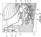
FIGS. 4 to 6 , the bearinghousing 30 includes anoil inlet 42 and anoil outlet 44. Oil may be delivered to theoil inlet 42 via anoil supply tube 46 or other like fluid delivery system. The oil may be provided from the engine's primary oil source, although other oil sources within the engine may be contemplated as well. Oil may be drained from the bearinghousing 30, for instance after lubricating and/or cooling thebearing 32 andshaft 20, via theoil outlet 44. The drained oil may then be circulated back to the main oil supply or delivered to another location in theengine 10. In the shown case, an air inlet 48 supplies air to the bearinghousing 30, for instance for various cooling or sealing purposes. - The positioning of the
oil inlet 42,oil outlet 44 andair inlet 48 about the bearinghousing 30 may vary. In the shown case, theoil outlet 44 is positioned at the circumferential bottom of the bearinghousing 30, while theoil inlet 42 andair inlet 48 are each positioned approximately sixty degrees apart from theoil outlet 44. Other positions may be contemplated as well. For instance, theoil inlet 42 may be positioned closer to one of theoil outlet 44 orair inlet 48. As will be discussed in further detail below, the delivery of oil via theoil manifold 34 may be optimized regardless of the positioning of theoil inlet 42 within the bearing housing. - The bearing
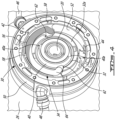
housing 30 has an annular body extending around the axis 11 with anouter wall 50 and aninner wall 52. The bearinghousing 30 further includes abearing seat 32a with which the outer race of thebearing 32 is engaged. As can be seen inFIGS. 5 and6 , a plurality of webbed cutouts orwindows 54 may be present in the annular body of the bearinghousing 30, for instance to introduce required bearing support flexibility or to reduce weight. In addition, the presence of such webbed cutouts orwindows 54 may allow additional airflow through the body of the bearinghousing 30 for various engine needs. The integratedoil manifold 34 protrudes from theinner wall 52 and generally follows the circular shape of theinner wall 52. In the shown case, a plurality of gaps orcutouts 56 are formed between connectingribs 58. These integratedribs 58 are formed between theoil manifold 34 and theinner wall 52. These gaps orcutouts 56 may contribute to a lower overall engine weight. In other cases, theoil manifold 34 may be completely flush with theinner wall 52. - The integrated
oil manifold 34 includes aninner oil channel 60 which receives oil via theoil inlet 42. Theinner oil channel 60 is defined in the annular body of the bearinghousing 30 and extends in the circumferential direction along an arc of circle around the axis 11. Theinner oil channel 60 directs the oil to one ormore oil jets 62 which direct the oil to thebearing 32, theshaft 20, and/or other internal components for lubrication and/or cooling purposes. In the shown case, theoil manifold 34 includes twooil jets 62 disposed at opposed circumferential ends of theoil channel 60. In the shown case, theinterior oil channel 60 extends radially inward towards each of the twooil jets 62 respectively at opposed ends of theinterior oil channel 60. As such, oil from theoil inlet 42 is diverted in two opposed circumferential directions once it reaches theinner oil channel 60 towards eachoil jet 62. Other numbers ofoil jets 62 may be contemplated as well based on the lubrication or cooling needs of a given engine. For instance, in a smaller engine, asingle oil jet 62 may suffice, whereas a larger engine may require fouroil jets 62. In the shown case, theoil jets 62 direct oil toinlets 40a in theoil scoop 40 for distribution to thebearing 32 andshaft 20, although other distribution techniques may be contemplated as well. - The circumferential spacing between the
oil jets 62 may vary, for instance based on the number ofoil jets 62 and the number and locations of theoil scoop inlets 40a. In the shown case, the twooil jets 62 are positioned approximately one hundred and eighty degrees apart. Such positioning may provide optimal lubrication and cooling to theshaft 20 andbearing 32. Other angles between theoil jets 62 may be contemplated as well, offering flexibility in optimizing the direction(s) from which thebearing 32 andshaft 20 receive oil. For instance, in anoil manifold 34 with threeoil jets 62, theoil jets 62 may be positioned around sixty degrees apart. As theoil manifold 34 follows the curvature of theinner wall 52, the spacing between theoil jets 62 can vary without concern of theoil manifold 34 interfering with components such as theoil scoop 40, bearing 32 orshaft 20. - The directions of the
oil jets 62 may vary as well. In the shown case, as can be seen inFIG. 4 , the oil jets are each directed tangentially towards the bearing 32,shaft 20 andoil scoop 40. In addition, theoil jets 62 are positioned to inject oil directly into theoil scoop inlets 40a. When theengine 10 is in use, theoil scoop 40 may remain stationary while theshaft 20 andbearing 32 rotate in a same direction, for instance counter-clockwise when viewed from an upstream engine direction, as the direction of the incoming oil stream. Other directions may be contemplated as well, for instance based on the positioning and number ofoil jets 62. - In the shown case, a
cover 64 is mounted to theoil manifold 34 to seal theinner oil channel 60. Thecover 64 can be welded, braced, or otherwise mounted to theoil manifold 34. Thecover 64 generally follows the curved shape of theoil manifold 34. In other cases, theinner oil channel 60 may be formed within theoil manifold 34 between the oil jet(s) 62 andoil inlet 42 and thus not require acover 64. - The circumferential span of the
oil manifold 34 may vary, for instance based on the number ofoil jets 62 or the desired angle betweenadjacent oil jets 62. In the shown case, theoil manifold 34 spans around one hundred and eighty degrees, or around half of the inner circumference of the bearinghousing 30. Other spans may be contemplated as well, for instance anoil manifold 34 spanning the entire circumference of theoil manifold 34 withnumerous oil jets 62 spaced along. In such cases with more than twooil jets 62,adjacent oil jets 62 may or may not be evenly spaced apart along theoil manifold 34. In addition, theoil inlet 42 can be positioned at various locations along the span of theoil manifold 34. In the shown case, theoil inlet 42 is circumferentially closer to one of the twooil jets 62, although this position may vary. As the position of theoil inlet 42 is variable, it may be a function of other engine design considerations. In the shown case, theoil inlet 42 meets theinner oil channel 60 partway between the twooil jets 62. Other oil entry points to theinner oil channel 60 may be contemplated as well. For instance, in some cases theoil inlet 42 may deliver oil to an end of theoil manifold 34, i.e. at one of the ends of theinner oil channel 60. In addition, while in the shown case theoil jets 62 are positioned at the ends of theinner oil channel 60, in other cases one ormore oil jets 62 may be positioned along the length of theinner oil channel 60. - The radial width of the
oil manifold 34, i.e. the distance that the integratedoil manifold 34 protrudes from theinner wall 52 of the bearinghousing 30, may vary. For instance, awider oil manifold 34 may be needed in cases of higher oil flows. Alternatively, the radial width of theoil manifold 34 should not exceed a value beyond which theoil manifold 34 may interfere with other components within the bearinghousing 30 such as theoil scoop 40, the bearing 32 or theshaft 20. The width and axial depth of theinner oil channel 60 may vary as well, for instance based on the required oil flow and the overall size of theoil manifold 34. In various cases, theinner oil channel 60 can have a variable axial or cross-sectional depth to optimize oil flow. For instance, theinner oil channel 60 may include an axial depth that increases from theoil inlet 42 towards the oil jet(s) 62 to promote the flow of oil towards the oil jet(s) 62, regardless of the circumferential positioning of theoil inlet 42. - As discussed above, the bearing
housing 30 with the integratedoil manifold 34 is manufactured or otherwise formed from a single piece of material, improving the durability relative to traditional add-on oil manifolds. Various manufacturing techniques may be contemplated, such as machining from a solid material, casting, or other suitable techniques. Compared to traditional standalone or non-integrated oil manifolds, there are fewer required manufacturing and assembly steps, as theoil manifold 34 does not need to be welded or brazed to the bearinghousing 30. As discussed above, in some cases, one or more gaps orcutouts 56 may be formed between sections of theoil manifold 34 and theinner wall 52. In such cases,such cutouts 56 may be drilled or otherwise extruded from the single-formed piece of material comprising the bearinghousing 30 with the integratedoil manifold 34, formingintegrated ribs 58 between theoil manifold 34 and theinner wall 52. Fewer pieces of manifold attachment hardware may be required as well. In addition, the part tolerances and positional relationships between theoil manifold 34 and the bearinghousing 30 may be improved relative to non-integrated oil manifolds as the two parts are integrated. As there are fewer welding and/or brazing joints that could potentially fail, the risk of loose hardware may be lowered with the integratedoil manifold 34 design. Fewer vibrations may occur due to the integrated design as well. - The bearing
housing 30 with the integratedoil manifold 34 may offer greater flexibility to optimize oil delivery relative to traditional non-integrated add-on oil manifolds. For instance, as theoil jets 62 may be positioned at any circumferential position within the bearinghousing 30, oil may be delivered to theshaft 20 and bearing 32 at optimal locations and from optimal angles, increasing performance. In addition, as theintegrated oil manifold 34 follows the circumference of theinner wall 52 of the bearinghousing 30, the positioning of the oil jets 62 (and its effect on the overall size of the oil manifold 34) will not pose interference risks with theshaft 20, bearing 32 oroil scoop 40. Further, the number ofoil jets 62 can be increased without having to dramatically alter the shape or number of components of theoil manifold 34. - The embodiments described in this document provide non-limiting examples of possible implementations of the present technology. Upon review of the present disclosure, a person of ordinary skill in the art will recognize that changes may be made to the embodiments described herein without departing from the scope of the present technology. Yet further modifications could be implemented by a person of ordinary skill in the art in view of the present disclosure, which modifications would be within the scope of the present technology.
Claims (11)
- A bearing housing (30) for supporting a bearing (32) of a gas turbine engine (10), the bearing housing (30) comprising:an annular body extending around an axis (11) and having an oil inlet (42) and an oil outlet (44); andan oil manifold (34) integrated into the annular body, the oil manifold (34) having an inner oil channel (60) defined in the annular body and extending circumferentially around the axis (11), the inner oil channel (60) in fluid communication with the oil inlet (42) and at least one oil jet (62) directed towards the bearing (32);characterised in that:
the bearing housing (30) and the oil manifold (34) are machined or otherwise formed as a single, unitary or monolithic piece. - The bearing housing (30) as defined in claim 1, wherein the inner oil channel (60) extends along an arc of circle, and wherein the at least one oil jet (62) includes two oil jets respectively disposed at opposed ends of the inner oil channel (60).
- The bearing housing (30) as defined in claim 2, wherein the interior oil channel (60) extends radially inward towards each of the two oil jets respectively at the opposed ends of the inner oil channel (60).
- The bearing housing (30) as defined in claim 1, 2 or 3, wherein the at least one oil jet (62) includes two circumferentially spaced-apart oil jets formed in the annular body and directed tangentially towards the bearing (32).
- The bearing housing (30) as defined in claim 2, 3 or 4, wherein the two oil jets are circumferentially disposed approximately one hundred and eighty degrees apart.
- The bearing housing (30) as defined in any preceding claim, wherein the inner oil channel (60) includes an axial depth that increases towards the at least one oil jet (62).
- The bearing housing (30) as defined in any preceding claim, further comprising a cover (64) mountable to the oil manifold (34) for sealing the inner oil channel (60).
- The bearing housing as defined in any preceding claim, further comprising a plurality of integrated ribs (58) formed between the oil manifold (34) and an inner wall (52) of the bearing housing (30).
- The bearing housing (30) as defined in any preceding claim, further comprising an oil scoop (40) radially aligned with the oil manifold (34) within the bearing housing (30) and disposed downstream of the bearing (32), the oil scoop (40) directing oil supplied from the at least one jet (62) to the bearing (32).
- The bearing housing (30) as defined in claim 9, wherein each at least one oil jet (62) is directed towards one or more inlets (40a) of the oil scoop (40).
- A gas turbine engine (10) comprising:a rotor mounted for rotation about an axis (11); anda bearing housing (30) as defined in any preceding claim, the bearing housing (30) including an interior chamber with a bearing (32) rotationally supporting the rotor.
Applications Claiming Priority (1)
| Application Number | Priority Date | Filing Date | Title |
|---|---|---|---|
| US17/123,278 US11572922B2 (en) | 2020-12-16 | 2020-12-16 | Bearing housing and method of making |
Publications (2)
| Publication Number | Publication Date |
|---|---|
| EP4036379A1 EP4036379A1 (en) | 2022-08-03 |
| EP4036379B1 true EP4036379B1 (en) | 2023-12-06 |
Family
ID=78918471
Family Applications (1)
| Application Number | Title | Priority Date | Filing Date |
|---|---|---|---|
| EP21215136.9A Active EP4036379B1 (en) | 2020-12-16 | 2021-12-16 | Bearing housing of a gas turbine engine |
Country Status (3)
| Country | Link |
|---|---|
| US (1) | US11572922B2 (en) |
| EP (1) | EP4036379B1 (en) |
| CA (1) | CA3140801A1 (en) |
Family Cites Families (8)
| Publication number | Priority date | Publication date | Assignee | Title |
|---|---|---|---|---|
| US2956824A (en) | 1957-12-27 | 1960-10-18 | Koppers Co Inc | Vented shaft seal |
| US4971184A (en) * | 1989-08-07 | 1990-11-20 | General Motors Corporation | Overrunning clutch with lubricant spreading and distribution means |
| US5301957A (en) | 1992-04-27 | 1994-04-12 | General Electric Company | Expanding circumferential seal with upper-cooled runner |
| US6976827B2 (en) * | 2003-10-14 | 2005-12-20 | Pratt & Whitney Canada Corp. | Rotor balancing device and method |
| US9057284B2 (en) * | 2012-04-30 | 2015-06-16 | United Technologies Corporation | Manifold for geared turbofan engine |
| US10267406B2 (en) * | 2013-07-07 | 2019-04-23 | United Technologies Corporation | Inseparable machined lubricant manifold |
| US9989083B2 (en) | 2015-05-26 | 2018-06-05 | Pratt & Whitney Canada Corp. | Seal and bearing assembly for a gas turbine engine and method of assembling same |
| FR3055309B1 (en) * | 2016-08-26 | 2018-08-17 | Safran Aircraft Engines | PASTE CHANGE SYSTEM EQUIPPED WITH MEANS FOR LUBRICATING A LOAD TRANSFER BEARING |
-
2020
- 2020-12-16 US US17/123,278 patent/US11572922B2/en active Active
-
2021
- 2021-11-30 CA CA3140801A patent/CA3140801A1/en active Pending
- 2021-12-16 EP EP21215136.9A patent/EP4036379B1/en active Active
Also Published As
| Publication number | Publication date |
|---|---|
| CA3140801A1 (en) | 2022-06-16 |
| US11572922B2 (en) | 2023-02-07 |
| EP4036379A1 (en) | 2022-08-03 |
| US20220186784A1 (en) | 2022-06-16 |
Similar Documents
| Publication | Publication Date | Title |
|---|---|---|
| US6280139B1 (en) | Radial split diffuser | |
| JP4091874B2 (en) | Secondary air supply device for gas turbine engine | |
| EP1892405B1 (en) | Gas turbine engine exhaust duct ventilation | |
| US12065950B1 (en) | Structural scroll case | |
| CN111102074B (en) | Oil pan housing for a gas turbine engine | |
| CN110005530A (en) | Compressor in gas-turbine unit is cooling | |
| CN114483203B (en) | Technology for inner shrouds used to cool gas turbine blades | |
| EP1809893B1 (en) | Stator for a jet engine, a jet engine comprising such a stator, and an aircraft comprising the jet engine | |
| EP4036379B1 (en) | Bearing housing of a gas turbine engine | |
| CN113090347B (en) | Air starter with bearing cooling | |
| EP4296471A1 (en) | Load transfer interface with spigot for compressor scroll housing | |
| JP7365418B2 (en) | gas turbine engine | |
| US11933187B2 (en) | Bearing housing assembly | |
| US12140048B1 (en) | Integrated centrifugal compressor diffuser and high pressure turbine vane assembly | |
| US11885242B2 (en) | Diffuser ring with air manifold | |
| US20250043726A1 (en) | Containment ring cavity pressurization system | |
| EP4467770A2 (en) | Turbine engine structure with an integral fluid reservoir |
Legal Events
| Date | Code | Title | Description |
|---|---|---|---|
| PUAI | Public reference made under article 153(3) epc to a published international application that has entered the european phase |
Free format text: ORIGINAL CODE: 0009012 |
|
| STAA | Information on the status of an ep patent application or granted ep patent |
Free format text: STATUS: THE APPLICATION HAS BEEN PUBLISHED |
|
| AK | Designated contracting states |
Kind code of ref document: A1 Designated state(s): AL AT BE BG CH CY CZ DE DK EE ES FI FR GB GR HR HU IE IS IT LI LT LU LV MC MK MT NL NO PL PT RO RS SE SI SK SM TR |
|
| STAA | Information on the status of an ep patent application or granted ep patent |
Free format text: STATUS: REQUEST FOR EXAMINATION WAS MADE |
|
| 17P | Request for examination filed |
Effective date: 20230203 |
|
| RBV | Designated contracting states (corrected) |
Designated state(s): AL AT BE BG CH CY CZ DE DK EE ES FI FR GB GR HR HU IE IS IT LI LT LU LV MC MK MT NL NO PL PT RO RS SE SI SK SM TR |
|
| GRAP | Despatch of communication of intention to grant a patent |
Free format text: ORIGINAL CODE: EPIDOSNIGR1 |
|
| STAA | Information on the status of an ep patent application or granted ep patent |
Free format text: STATUS: GRANT OF PATENT IS INTENDED |
|
| RIC1 | Information provided on ipc code assigned before grant |
Ipc: F02C 7/28 20060101ALI20230531BHEP Ipc: F01D 25/20 20060101ALI20230531BHEP Ipc: F01D 25/18 20060101AFI20230531BHEP |
|
| INTG | Intention to grant announced |
Effective date: 20230703 |
|
| GRAS | Grant fee paid |
Free format text: ORIGINAL CODE: EPIDOSNIGR3 |
|
| GRAA | (expected) grant |
Free format text: ORIGINAL CODE: 0009210 |
|
| STAA | Information on the status of an ep patent application or granted ep patent |
Free format text: STATUS: THE PATENT HAS BEEN GRANTED |
|
| AK | Designated contracting states |
Kind code of ref document: B1 Designated state(s): AL AT BE BG CH CY CZ DE DK EE ES FI FR GB GR HR HU IE IS IT LI LT LU LV MC MK MT NL NO PL PT RO RS SE SI SK SM TR |
|
| REG | Reference to a national code |
Ref country code: GB Ref legal event code: FG4D |
|
| REG | Reference to a national code |
Ref country code: CH Ref legal event code: EP |
|
| REG | Reference to a national code |
Ref country code: DE Ref legal event code: R096 Ref document number: 602021007471 Country of ref document: DE |
|
| REG | Reference to a national code |
Ref country code: IE Ref legal event code: FG4D |
|
| REG | Reference to a national code |
Ref country code: LT Ref legal event code: MG9D |
|
| PG25 | Lapsed in a contracting state [announced via postgrant information from national office to epo] |
Ref country code: GR Free format text: LAPSE BECAUSE OF FAILURE TO SUBMIT A TRANSLATION OF THE DESCRIPTION OR TO PAY THE FEE WITHIN THE PRESCRIBED TIME-LIMIT Effective date: 20240307 |
|
| REG | Reference to a national code |
Ref country code: NL Ref legal event code: MP Effective date: 20231206 |
|
| PG25 | Lapsed in a contracting state [announced via postgrant information from national office to epo] |
Ref country code: LT Free format text: LAPSE BECAUSE OF FAILURE TO SUBMIT A TRANSLATION OF THE DESCRIPTION OR TO PAY THE FEE WITHIN THE PRESCRIBED TIME-LIMIT Effective date: 20231206 |
|
| PG25 | Lapsed in a contracting state [announced via postgrant information from national office to epo] |
Ref country code: ES Free format text: LAPSE BECAUSE OF FAILURE TO SUBMIT A TRANSLATION OF THE DESCRIPTION OR TO PAY THE FEE WITHIN THE PRESCRIBED TIME-LIMIT Effective date: 20231206 |
|
| PG25 | Lapsed in a contracting state [announced via postgrant information from national office to epo] |
Ref country code: LT Free format text: LAPSE BECAUSE OF FAILURE TO SUBMIT A TRANSLATION OF THE DESCRIPTION OR TO PAY THE FEE WITHIN THE PRESCRIBED TIME-LIMIT Effective date: 20231206 Ref country code: GR Free format text: LAPSE BECAUSE OF FAILURE TO SUBMIT A TRANSLATION OF THE DESCRIPTION OR TO PAY THE FEE WITHIN THE PRESCRIBED TIME-LIMIT Effective date: 20240307 Ref country code: ES Free format text: LAPSE BECAUSE OF FAILURE TO SUBMIT A TRANSLATION OF THE DESCRIPTION OR TO PAY THE FEE WITHIN THE PRESCRIBED TIME-LIMIT Effective date: 20231206 Ref country code: BG Free format text: LAPSE BECAUSE OF FAILURE TO SUBMIT A TRANSLATION OF THE DESCRIPTION OR TO PAY THE FEE WITHIN THE PRESCRIBED TIME-LIMIT Effective date: 20240306 |
|
| REG | Reference to a national code |
Ref country code: AT Ref legal event code: MK05 Ref document number: 1638597 Country of ref document: AT Kind code of ref document: T Effective date: 20231206 |
|
| PG25 | Lapsed in a contracting state [announced via postgrant information from national office to epo] |
Ref country code: NL Free format text: LAPSE BECAUSE OF FAILURE TO SUBMIT A TRANSLATION OF THE DESCRIPTION OR TO PAY THE FEE WITHIN THE PRESCRIBED TIME-LIMIT Effective date: 20231206 |
|
| PG25 | Lapsed in a contracting state [announced via postgrant information from national office to epo] |
Ref country code: SE Free format text: LAPSE BECAUSE OF FAILURE TO SUBMIT A TRANSLATION OF THE DESCRIPTION OR TO PAY THE FEE WITHIN THE PRESCRIBED TIME-LIMIT Effective date: 20231206 Ref country code: RS Free format text: LAPSE BECAUSE OF FAILURE TO SUBMIT A TRANSLATION OF THE DESCRIPTION OR TO PAY THE FEE WITHIN THE PRESCRIBED TIME-LIMIT Effective date: 20231206 Ref country code: NO Free format text: LAPSE BECAUSE OF FAILURE TO SUBMIT A TRANSLATION OF THE DESCRIPTION OR TO PAY THE FEE WITHIN THE PRESCRIBED TIME-LIMIT Effective date: 20240306 Ref country code: NL Free format text: LAPSE BECAUSE OF FAILURE TO SUBMIT A TRANSLATION OF THE DESCRIPTION OR TO PAY THE FEE WITHIN THE PRESCRIBED TIME-LIMIT Effective date: 20231206 Ref country code: LV Free format text: LAPSE BECAUSE OF FAILURE TO SUBMIT A TRANSLATION OF THE DESCRIPTION OR TO PAY THE FEE WITHIN THE PRESCRIBED TIME-LIMIT Effective date: 20231206 Ref country code: HR Free format text: LAPSE BECAUSE OF FAILURE TO SUBMIT A TRANSLATION OF THE DESCRIPTION OR TO PAY THE FEE WITHIN THE PRESCRIBED TIME-LIMIT Effective date: 20231206 |
|
| PG25 | Lapsed in a contracting state [announced via postgrant information from national office to epo] |
Ref country code: IS Free format text: LAPSE BECAUSE OF FAILURE TO SUBMIT A TRANSLATION OF THE DESCRIPTION OR TO PAY THE FEE WITHIN THE PRESCRIBED TIME-LIMIT Effective date: 20240406 |
|
| PG25 | Lapsed in a contracting state [announced via postgrant information from national office to epo] |
Ref country code: AT Free format text: LAPSE BECAUSE OF FAILURE TO SUBMIT A TRANSLATION OF THE DESCRIPTION OR TO PAY THE FEE WITHIN THE PRESCRIBED TIME-LIMIT Effective date: 20231206 Ref country code: CZ Free format text: LAPSE BECAUSE OF FAILURE TO SUBMIT A TRANSLATION OF THE DESCRIPTION OR TO PAY THE FEE WITHIN THE PRESCRIBED TIME-LIMIT Effective date: 20231206 |
|
| PG25 | Lapsed in a contracting state [announced via postgrant information from national office to epo] |
Ref country code: SK Free format text: LAPSE BECAUSE OF FAILURE TO SUBMIT A TRANSLATION OF THE DESCRIPTION OR TO PAY THE FEE WITHIN THE PRESCRIBED TIME-LIMIT Effective date: 20231206 |
|
| PG25 | Lapsed in a contracting state [announced via postgrant information from national office to epo] |
Ref country code: SM Free format text: LAPSE BECAUSE OF FAILURE TO SUBMIT A TRANSLATION OF THE DESCRIPTION OR TO PAY THE FEE WITHIN THE PRESCRIBED TIME-LIMIT Effective date: 20231206 Ref country code: SK Free format text: LAPSE BECAUSE OF FAILURE TO SUBMIT A TRANSLATION OF THE DESCRIPTION OR TO PAY THE FEE WITHIN THE PRESCRIBED TIME-LIMIT Effective date: 20231206 Ref country code: RO Free format text: LAPSE BECAUSE OF FAILURE TO SUBMIT A TRANSLATION OF THE DESCRIPTION OR TO PAY THE FEE WITHIN THE PRESCRIBED TIME-LIMIT Effective date: 20231206 Ref country code: IT Free format text: LAPSE BECAUSE OF FAILURE TO SUBMIT A TRANSLATION OF THE DESCRIPTION OR TO PAY THE FEE WITHIN THE PRESCRIBED TIME-LIMIT Effective date: 20231206 Ref country code: IS Free format text: LAPSE BECAUSE OF FAILURE TO SUBMIT A TRANSLATION OF THE DESCRIPTION OR TO PAY THE FEE WITHIN THE PRESCRIBED TIME-LIMIT Effective date: 20240406 Ref country code: EE Free format text: LAPSE BECAUSE OF FAILURE TO SUBMIT A TRANSLATION OF THE DESCRIPTION OR TO PAY THE FEE WITHIN THE PRESCRIBED TIME-LIMIT Effective date: 20231206 Ref country code: CZ Free format text: LAPSE BECAUSE OF FAILURE TO SUBMIT A TRANSLATION OF THE DESCRIPTION OR TO PAY THE FEE WITHIN THE PRESCRIBED TIME-LIMIT Effective date: 20231206 Ref country code: AT Free format text: LAPSE BECAUSE OF FAILURE TO SUBMIT A TRANSLATION OF THE DESCRIPTION OR TO PAY THE FEE WITHIN THE PRESCRIBED TIME-LIMIT Effective date: 20231206 |
|
| PG25 | Lapsed in a contracting state [announced via postgrant information from national office to epo] |
Ref country code: PL Free format text: LAPSE BECAUSE OF FAILURE TO SUBMIT A TRANSLATION OF THE DESCRIPTION OR TO PAY THE FEE WITHIN THE PRESCRIBED TIME-LIMIT Effective date: 20231206 Ref country code: PT Free format text: LAPSE BECAUSE OF FAILURE TO SUBMIT A TRANSLATION OF THE DESCRIPTION OR TO PAY THE FEE WITHIN THE PRESCRIBED TIME-LIMIT Effective date: 20240408 |
|
| PG25 | Lapsed in a contracting state [announced via postgrant information from national office to epo] |
Ref country code: LU Free format text: LAPSE BECAUSE OF NON-PAYMENT OF DUE FEES Effective date: 20231216 |
|
| REG | Reference to a national code |
Ref country code: BE Ref legal event code: MM Effective date: 20231231 |
|
| PG25 | Lapsed in a contracting state [announced via postgrant information from national office to epo] |
Ref country code: PT Free format text: LAPSE BECAUSE OF FAILURE TO SUBMIT A TRANSLATION OF THE DESCRIPTION OR TO PAY THE FEE WITHIN THE PRESCRIBED TIME-LIMIT Effective date: 20240408 Ref country code: PL Free format text: LAPSE BECAUSE OF FAILURE TO SUBMIT A TRANSLATION OF THE DESCRIPTION OR TO PAY THE FEE WITHIN THE PRESCRIBED TIME-LIMIT Effective date: 20231206 Ref country code: LU Free format text: LAPSE BECAUSE OF NON-PAYMENT OF DUE FEES Effective date: 20231216 |
|
| REG | Reference to a national code |
Ref country code: DE Ref legal event code: R026 Ref document number: 602021007471 Country of ref document: DE |
|
| PLBI | Opposition filed |
Free format text: ORIGINAL CODE: 0009260 |
|
| PLAX | Notice of opposition and request to file observation + time limit sent |
Free format text: ORIGINAL CODE: EPIDOSNOBS2 |
|
| PG25 | Lapsed in a contracting state [announced via postgrant information from national office to epo] |
Ref country code: MC Free format text: LAPSE BECAUSE OF FAILURE TO SUBMIT A TRANSLATION OF THE DESCRIPTION OR TO PAY THE FEE WITHIN THE PRESCRIBED TIME-LIMIT Effective date: 20231206 |
|
| 26 | Opposition filed |
Opponent name: SAFRAN AIRCRAFT ENGINES Effective date: 20240903 |
|
| REG | Reference to a national code |
Ref country code: IE Ref legal event code: MM4A |
|
| PG25 | Lapsed in a contracting state [announced via postgrant information from national office to epo] |
Ref country code: IE Free format text: LAPSE BECAUSE OF NON-PAYMENT OF DUE FEES Effective date: 20231216 |
|
| PG25 | Lapsed in a contracting state [announced via postgrant information from national office to epo] |
Ref country code: DK Free format text: LAPSE BECAUSE OF FAILURE TO SUBMIT A TRANSLATION OF THE DESCRIPTION OR TO PAY THE FEE WITHIN THE PRESCRIBED TIME-LIMIT Effective date: 20231206 |
|
| PG25 | Lapsed in a contracting state [announced via postgrant information from national office to epo] |
Ref country code: BE Free format text: LAPSE BECAUSE OF NON-PAYMENT OF DUE FEES Effective date: 20231231 |
|
| PG25 | Lapsed in a contracting state [announced via postgrant information from national office to epo] |
Ref country code: SI Free format text: LAPSE BECAUSE OF FAILURE TO SUBMIT A TRANSLATION OF THE DESCRIPTION OR TO PAY THE FEE WITHIN THE PRESCRIBED TIME-LIMIT Effective date: 20231206 |
|
| PG25 | Lapsed in a contracting state [announced via postgrant information from national office to epo] |
Ref country code: SI Free format text: LAPSE BECAUSE OF FAILURE TO SUBMIT A TRANSLATION OF THE DESCRIPTION OR TO PAY THE FEE WITHIN THE PRESCRIBED TIME-LIMIT Effective date: 20231206 Ref country code: IE Free format text: LAPSE BECAUSE OF NON-PAYMENT OF DUE FEES Effective date: 20231216 Ref country code: DK Free format text: LAPSE BECAUSE OF FAILURE TO SUBMIT A TRANSLATION OF THE DESCRIPTION OR TO PAY THE FEE WITHIN THE PRESCRIBED TIME-LIMIT Effective date: 20231206 Ref country code: BE Free format text: LAPSE BECAUSE OF NON-PAYMENT OF DUE FEES Effective date: 20231231 |
|
| PLBB | Reply of patent proprietor to notice(s) of opposition received |
Free format text: ORIGINAL CODE: EPIDOSNOBS3 |
|
| PG25 | Lapsed in a contracting state [announced via postgrant information from national office to epo] |
Ref country code: FI Free format text: LAPSE BECAUSE OF FAILURE TO SUBMIT A TRANSLATION OF THE DESCRIPTION OR TO PAY THE FEE WITHIN THE PRESCRIBED TIME-LIMIT Effective date: 20231207 |
|
| PG25 | Lapsed in a contracting state [announced via postgrant information from national office to epo] |
Ref country code: CY Free format text: LAPSE BECAUSE OF FAILURE TO SUBMIT A TRANSLATION OF THE DESCRIPTION OR TO PAY THE FEE WITHIN THE PRESCRIBED TIME-LIMIT; INVALID AB INITIO Effective date: 20211216 |
|
| REG | Reference to a national code |
Ref country code: CH Ref legal event code: PL |
|
| PG25 | Lapsed in a contracting state [announced via postgrant information from national office to epo] |
Ref country code: CH Free format text: LAPSE BECAUSE OF NON-PAYMENT OF DUE FEES Effective date: 20241231 |
|
| PG25 | Lapsed in a contracting state [announced via postgrant information from national office to epo] |
Ref country code: TR Free format text: LAPSE BECAUSE OF FAILURE TO SUBMIT A TRANSLATION OF THE DESCRIPTION OR TO PAY THE FEE WITHIN THE PRESCRIBED TIME-LIMIT Effective date: 20231206 |
|
| REG | Reference to a national code |
Ref country code: CH Ref legal event code: W10 Free format text: ST27 STATUS EVENT CODE: U-0-0-W10-W00 (AS PROVIDED BY THE NATIONAL OFFICE) Effective date: 20251231 |
|
| PGFP | Annual fee paid to national office [announced via postgrant information from national office to epo] |
Ref country code: DE Payment date: 20251126 Year of fee payment: 5 |
|
| PGFP | Annual fee paid to national office [announced via postgrant information from national office to epo] |
Ref country code: GB Payment date: 20251119 Year of fee payment: 5 |
|
| PGFP | Annual fee paid to national office [announced via postgrant information from national office to epo] |
Ref country code: FR Payment date: 20251119 Year of fee payment: 5 |
|
| P01 | Opt-out of the competence of the unified patent court (upc) registered |
Free format text: CASE NUMBER: UPC_APP_0000171_4036379/2026 Effective date: 20260105 |