EP4036372A1 - Rotor balance assembly - Google Patents
Rotor balance assembly Download PDFInfo
- Publication number
- EP4036372A1 EP4036372A1 EP22154633.6A EP22154633A EP4036372A1 EP 4036372 A1 EP4036372 A1 EP 4036372A1 EP 22154633 A EP22154633 A EP 22154633A EP 4036372 A1 EP4036372 A1 EP 4036372A1
- Authority
- EP
- European Patent Office
- Prior art keywords
- slot
- rotor
- annular flange
- rotor assembly
- flat portion
- Prior art date
- Legal status (The legal status is an assumption and is not a legal conclusion. Google has not performed a legal analysis and makes no representation as to the accuracy of the status listed.)
- Granted
Links
Images




Classifications
-
- F—MECHANICAL ENGINEERING; LIGHTING; HEATING; WEAPONS; BLASTING
- F01—MACHINES OR ENGINES IN GENERAL; ENGINE PLANTS IN GENERAL; STEAM ENGINES
- F01D—NON-POSITIVE DISPLACEMENT MACHINES OR ENGINES, e.g. STEAM TURBINES
- F01D5/00—Blades; Blade-carrying members; Heating, heat-insulating, cooling or antivibration means on the blades or the members
- F01D5/02—Blade-carrying members, e.g. rotors
- F01D5/027—Arrangements for balancing
-
- F—MECHANICAL ENGINEERING; LIGHTING; HEATING; WEAPONS; BLASTING
- F01—MACHINES OR ENGINES IN GENERAL; ENGINE PLANTS IN GENERAL; STEAM ENGINES
- F01D—NON-POSITIVE DISPLACEMENT MACHINES OR ENGINES, e.g. STEAM TURBINES
- F01D5/00—Blades; Blade-carrying members; Heating, heat-insulating, cooling or antivibration means on the blades or the members
- F01D5/02—Blade-carrying members, e.g. rotors
- F01D5/025—Fixing blade carrying members on shafts
-
- F—MECHANICAL ENGINEERING; LIGHTING; HEATING; WEAPONS; BLASTING
- F01—MACHINES OR ENGINES IN GENERAL; ENGINE PLANTS IN GENERAL; STEAM ENGINES
- F01D—NON-POSITIVE DISPLACEMENT MACHINES OR ENGINES, e.g. STEAM TURBINES
- F01D5/00—Blades; Blade-carrying members; Heating, heat-insulating, cooling or antivibration means on the blades or the members
- F01D5/02—Blade-carrying members, e.g. rotors
- F01D5/06—Rotors for more than one axial stage, e.g. of drum or multiple disc type; Details thereof, e.g. shafts, shaft connections
- F01D5/066—Connecting means for joining rotor-discs or rotor-elements together, e.g. by a central bolt, by clamps
-
- F—MECHANICAL ENGINEERING; LIGHTING; HEATING; WEAPONS; BLASTING
- F04—POSITIVE - DISPLACEMENT MACHINES FOR LIQUIDS; PUMPS FOR LIQUIDS OR ELASTIC FLUIDS
- F04D—NON-POSITIVE-DISPLACEMENT PUMPS
- F04D29/00—Details, component parts, or accessories
- F04D29/26—Rotors specially for elastic fluids
- F04D29/32—Rotors specially for elastic fluids for axial flow pumps
- F04D29/321—Rotors specially for elastic fluids for axial flow pumps for axial flow compressors
-
- F—MECHANICAL ENGINEERING; LIGHTING; HEATING; WEAPONS; BLASTING
- F04—POSITIVE - DISPLACEMENT MACHINES FOR LIQUIDS; PUMPS FOR LIQUIDS OR ELASTIC FLUIDS
- F04D—NON-POSITIVE-DISPLACEMENT PUMPS
- F04D29/00—Details, component parts, or accessories
- F04D29/66—Combating cavitation, whirls, noise, vibration or the like; Balancing
- F04D29/661—Combating cavitation, whirls, noise, vibration or the like; Balancing especially adapted for elastic fluid pumps
- F04D29/662—Balancing of rotors
-
- F—MECHANICAL ENGINEERING; LIGHTING; HEATING; WEAPONS; BLASTING
- F05—INDEXING SCHEMES RELATING TO ENGINES OR PUMPS IN VARIOUS SUBCLASSES OF CLASSES F01-F04
- F05D—INDEXING SCHEME FOR ASPECTS RELATING TO NON-POSITIVE-DISPLACEMENT MACHINES OR ENGINES, GAS-TURBINES OR JET-PROPULSION PLANTS
- F05D2250/00—Geometry
- F05D2250/70—Shape
- F05D2250/72—Shape symmetric
-
- F—MECHANICAL ENGINEERING; LIGHTING; HEATING; WEAPONS; BLASTING
- F05—INDEXING SCHEMES RELATING TO ENGINES OR PUMPS IN VARIOUS SUBCLASSES OF CLASSES F01-F04
- F05D—INDEXING SCHEME FOR ASPECTS RELATING TO NON-POSITIVE-DISPLACEMENT MACHINES OR ENGINES, GAS-TURBINES OR JET-PROPULSION PLANTS
- F05D2260/00—Function
- F05D2260/15—Load balancing
-
- F—MECHANICAL ENGINEERING; LIGHTING; HEATING; WEAPONS; BLASTING
- F05—INDEXING SCHEMES RELATING TO ENGINES OR PUMPS IN VARIOUS SUBCLASSES OF CLASSES F01-F04
- F05D—INDEXING SCHEME FOR ASPECTS RELATING TO NON-POSITIVE-DISPLACEMENT MACHINES OR ENGINES, GAS-TURBINES OR JET-PROPULSION PLANTS
- F05D2260/00—Function
- F05D2260/30—Retaining components in desired mutual position
-
- F—MECHANICAL ENGINEERING; LIGHTING; HEATING; WEAPONS; BLASTING
- F05—INDEXING SCHEMES RELATING TO ENGINES OR PUMPS IN VARIOUS SUBCLASSES OF CLASSES F01-F04
- F05D—INDEXING SCHEME FOR ASPECTS RELATING TO NON-POSITIVE-DISPLACEMENT MACHINES OR ENGINES, GAS-TURBINES OR JET-PROPULSION PLANTS
- F05D2260/00—Function
- F05D2260/96—Preventing, counteracting or reducing vibration or noise
-
- G—PHYSICS
- G01—MEASURING; TESTING
- G01M—TESTING STATIC OR DYNAMIC BALANCE OF MACHINES OR STRUCTURES; TESTING OF STRUCTURES OR APPARATUS, NOT OTHERWISE PROVIDED FOR
- G01M1/00—Testing static or dynamic balance of machines or structures
- G01M1/30—Compensating imbalance
- G01M1/32—Compensating imbalance by adding material to the body to be tested, e.g. by correcting-weights
Definitions
- the invention relates generally to rotors for gas turbine engines and, more particularly, to balancing features for such rotors.
- Rotor eccentricities are a main source of engine vibration, and eccentricities can be alleviated by rotor balancing. Examples of how rotors are balanced without compromising their structural integrity include oversizing a part of the rotor disk, often referred to as a sacrificial balance appendage, rim or flange, and then either adding balancing weights or selectively removing material from that part.
- a rotor assembly for a gas turbine engine comprising: a rotor including a rotor disc rotatable about a central axis, the rotor having a pair of opposite axially facing faces; an annular flange protruding axially from one of the opposite axially facing faces, the annular flange having a circumference disposed about the central axis, the annular flange including: a plurality of protrusions axisymmetrically disposed about the circumference of the annular flange, each protrusion extending axially from a base portion of the annular flange to a respective protrusion end, each protrusion having a mounting aperture for selectively receiving a balancing feature; and a plurality of slots axisymmetrically disposed about the circumference of the annular flange between adjacent protrusions, each slot including a pair of converging flat portions extending axially inwardly from an adjacent protrusion end,
- each slot each have a radius approximately equal to the slot depth.
- each converging flat portion forms an angle ranging from twenty to forty degrees with respect to a slot longitudinal axis in line with the annular flange.
- the inner flat portion of each slot has a width that is at least one tenth as great as the slot depth.
- the annular flange has a radial thickness with reference to the central axis that is at least eighty-five percent as great as the slot depth of each slot.
- the annular flange includes twenty-four of the plurality of protrusions axisymmetrically disposed about the circumference of the annular flange.
- the rotor disc is operable to rotate at a speed of at least 50,000 RPM.
- the annular flange protrudes axially in a direction parallel to the central axis from the rotor disc.
- the rotor further includes a rotor disc cover plate, wherein the annular flange protrudes axially in a direction parallel to the central axis from the rotor disc cover plate.
- a rotor assembly for a gas turbine engine comprising: a rotor including a rotor disc rotatable about a central axis, the rotor having a pair of opposite axially facing faces; a pair of annular flanges, each annular flange protruding axially from one of the opposite axially facing faces, each annular flange having a circumference disposed about the central longitudinal axis, each annular flange including: a plurality of protrusions axisymmetrically disposed about the circumference of the annular flange, each protrusion extending axially from a base portion of the annular flange to a respective protrusion end, each protrusion having a mounting aperture for selectively receiving a balancing feature; and a plurality of slots axisymmetrically disposed about the circumference of the annular flange between adjacent protrusions, each slot including a pair of converging flat portions extending axial
- the curved portions in each slot each have a radius measuring between 0.105 and 0.145 inches (2.67 and 3.68 mm).
- each converging flat portion forms an angle ranging from twenty-nine to thirty-one degrees with respect to a slot longitudinal axis in line with the corresponding annular flange.
- each annular flange has a radial thickness with reference to the central axis measuring approximately 0.115 inches (2.92 mm).
- each protrusion end has a width taken between two adjacent slots measuring approximately 0.270 inches (6.86 mm).
- each annular flange includes twenty-four of the plurality of protrusions axisymmetrically disposed about the circumference of each annular flange.
- the rotor disc is operable to rotate at a speed of at least 50,000 RPM.
- the rotor further includes a rotor disc cover plate, wherein a first one of the annular flanges protrudes axially in a first direction parallel to the central axis from the rotor disc, and a second one of the annular flanges protrudes axially in a second direction parallel to the central axis opposite the first direction from the rotor disc cover plate.
- a rotor assembly for a gas turbine engine comprising: a rotor including a rotor disc rotatable at a rotational operation speed about a central axis and a rotor disc cover plate mounted to the rotor disc; a pair of annular flanges, a first annular flange protruding axially from the rotor disc in a first direction parallel to the central axis, a second annular flange protruding axially from the rotor disc cover plate in a second direction parallel to the central axis opposite the first direction, each annular flange having a circumference disposed about the central axis, each annular flange having a radial thickness with reference to the central axis, each annular flange having a middle radius defined by a radial distance between the central axis and a midpoint of each annular flange along the radial thickness, each annular flange including: a
- each slot has a slot depth extending normally from the adjacent protrusion end to the inner end of each slot, said slot depth at least as great as an adjacent mounting aperture depth extending normally from the adjacent protrusion end to a far end of the corresponding mounting aperture.
- each slot each have a radius approximately equal to the slot depth.
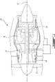
- FIG. 1 illustrates a gas turbine engine 10 of a type preferably provided for use in subsonic flight, generally comprising in serial flow communication a fan 12 through which ambient air is propelled, a compressor section 14 for pressurizing the air, a combustor 16 in which the compressed air is mixed with fuel and ignited for generating an annular stream of hot combustion gases, and a turbine section 18 for extracting energy from the combustion gases.
- a shaft 20 interconnects the fan 12, the compressor section 14 and the turbine section 18. While FIG. 1 shows gas turbine engine 10 to be a turbofan gas turbine engine, it is understood that the present disclosure is applicable to other types of gas turbine engines as well.
- a rotor assembly 22 which can be used in the gas turbine engine 10 of FIG. 1 or in any adequate type of gas turbine engine 10 is shown.
- the rotor assembly 22 is operable for rotation about a central axis 11.
- the rotor assembly 22 is a high pressure turbine (HPT) stage of a multistage turbine section 18 rotating at around 50,000 RPM or higher.
- HPT high pressure turbine
- the present disclosure may be applicable to other rotors within a gas turbine engine, as will be discussed in further detail below.
- the rotor assembly 22 includes a rotor having a rotor disc 24 to be mounted around a drive shaft 20 (shown in FIG. 1 ).
- the rotor includes a hub portion 26 having a central bore 28 through which the drive shaft 20 is inserted.
- the rotor includes a frustoconical web portion 30 extending generally radially from the hub portion 26.
- the rotor also has two opposite axially facing faces 32, 34 with reference to a rotor disc axis Y normal to the central axis 11. Opposite faces 32, 34 may be referred to as the first opposite face 32 and the second opposite face 34.
- the rotor includes a rotor disc cover plate 36 mounted to the first opposite face 32, although other configurations may be contemplated as well.
- the rotor disc cover plate 36 is mounted in front of the first opposite face's 32 web portion 30, for instance via fasteners 36a or other mounting hardware, while the web portion 30 is exposed on the second opposite face 34.
- the web portions 30 are exposed on both the first opposite face 32 and the second opposite face 34.
- the rotor includes an outer periphery portion 38 encircling the web portion 30.
- the hub portion 26, the web portion 30 and the outer periphery portion 38 in the illustrated example are made integral with each other and form a monolithic piece, while the shown rotor disc cover plate 36 is mountable to the rotor, for instance via fasteners 36a.
- the monolithic rotor can be made of a single material. Other rotor disc constructions may be contemplated as well.
- the rotor assembly 22 includes a plurality of circumferentially-disposed and radially extending blades 40 mounted in corresponding blade-receiving slots 42 provided in the outer periphery portion 38 for receiving roots of the blades 40.
- the number of blades 40 may vary, for instance based on the type of rotor assembly 22 or the type of engine 10.
- the slots 42 are designed to prevent the blades 40 from being ejected radially during rotation.
- Other components such as fixing rivets, spring plates, etc., may be provided in the rotor assembly 22, depending on the design.
- blades 40 that are made integral with the rotor, i.e. forming a monolithic assembly may be contemplated as well.
- the rotor disc cover plate 36 includes an inlet 36b ( Fig. 2c ) to provide a cooling flow to the blades 40 through an annular cooling channel 36c between the rotor disc cover plate 36 and the corresponding web portion 30.
- Other methods for cooling the blades 40 may be contemplated as well.
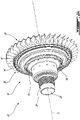
- the illustrated rotor assembly 22 has two rotor balancing assemblies each including an annular flange or circular and scalloped appendage 44, one on each opposite face 32, 34.
- Each flange 44 is coaxially disposed with reference to the central axis 11 and may also be referred to as a balancing flange or rim.
- flanges 44 may be referred to as 'horizontal balancing rims', and the combination of the two flanges 44 may be referred to as a 'two-plane balancing system'.
- the illustrated example shows two flanges 44, in other cases it is possible to provide only one instead of two. Such a sole flange 44 could then be on either face opposite 32 or 34. It is also possible to provide two or more flanges 44 on one side and none or a different number on the other side.
- the two flanges 44 are opposed relative to the rotor disc axis Y spanning through a midpoint of the outer periphery portion 38, yet are identical in size and shape. As such, they may be referred to as 'like' flanges 44. In other cases, any flange 44 on one side may not necessarily need to be identical in size and/or in shape compared to any flange on the other side.
- the flange 44 on the first opposite face 32 protrudes or projects generally longitudinally forward or axially relative to the central axis 11 from the rotor disc cover plate 36 while the flange 44 on the second opposite face 34 protrudes or projects generally longitudinally aft or axially from the web portion 30. In other cases, for instance where the rotor assembly 22 does not include a rotor disc cover plate 36, the flange 44 on the first opposite face 32 may protrude longitudinally forward from the web portion 30.
- each flange 44 comprises a base portion or root 46 that can be integrally connected to the web portion 30 or the cover plate 36, respectively, thereby being part of the rotor disc 24 or the cover plate 36.
- the flange 44 may be positioned elsewhere on the rotor, for instance on the outer periphery portion 38 or on the hub portion 26. Other positions may be contemplated as well.
- the base portion 46 of each flange 44 is circumferentially continuous.
- the flanges 44 may be connected to the rest of the rotor without being made integral thereto.
- a flange 44 could be connected by welding or brazing, by using fasteners, etc.
- each flange 44 has an inboard surface 48 and an outboard surface 50 and extend from the base portion 46 at the web portion 30 to a free or aft end 52.
- each flange 44 may be operable to form a generally annular portion of the rotor where internal stresses during operation of the engine 10 will be below a given crack propagation threshold.
- Each flange 44 may include a raised shoulder 44a towards the base portion 46 on the outboard surface 50, for instance to provide additional support when the weights are added.
- each flange 44 includes a plurality of circumferentially spaced-apart protrusions or fingers 54 at their free end 52.
- These protrusions 54 are the locations at which weights can be added to the rotor assembly 22 for balancing purposes, as will be discussed in further detail below.
- the protrusions 54 project or extend substantially axially from the base portion 46 of the corresponding flange 44 and terminate at protrusion ends 54a along the free end 52 of the flange 44.
- the protrusions 54 are axisymmetrically disposed with reference to the central axis 11 and are substantially identical. As such, they may be referred to as 'like' protrusions 54.
- each flange 44 includes twenty-four protrusions 54, although other numbers of protrusions 54 may be contemplated as well.
- the protrusions 54 are delimited circumferentially by a plurality of axisymmetrically spaced-apart stress-relieving slots 56, also referred to as scallop-shaped cutouts or recesses. These slots 56 are operable to relieve various stresses relating to, for instance, the weight added to the protrusions 54 for balancing purposes and the rotational forces acting upon the rotor assembly 22 in use.
- the slots 56 are formed on a radially-extending end face 52a at the free end 52 of the flange 44.
- the slots 56 are substantially identical to each other, and thus may be referred to as 'like' slots 56.
- Each of the slots 56 has an internal wall with a shape or slope minimizing the stress concentration within the slot 56, as will be discussed in the further detail below.
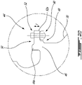
- each slot includes a pair of converging flat portions 56a, a pair of curved portions 56b, and an inner flat portion 56c at an inner end of each slot 56.
- the converging flat portions 56a extend axially inwardly from an adjacent protrusion end 54a.
- the pair of curved portions 56b respectively join each converging flat portion 56a to the inner flat portion 56c in each slot 56.
- the slots 56 are designed so as to reduce various internal stresses such as hoop stresses caused by the rotation of the rotor assembly 22 in operation, which may extend the life expectancy of the various components.
- the slots 56 may be machined in the free end 52 of each flange 44, for instance by using a rotating tool or another technique. Such machining of the slots 56 thus forms the protrusions 54.
- Each slot 56 in the illustrated example is oriented substantially radially with reference to the central axis 11.
- each slot 56 includes a pair of converging flat portions 56a extending axially inwardly from a respective protrusion end 54a and a pair of curved portions 56b meeting at an inner end of each slot 56.
- the pair of curved portions 56b respectively join each converging flat portion 56a to the inner end of each slot 56.
- the slots 56 would not include end flat portions 56c.
- Other arrangements for each slot 56 may be contemplated as well.
- each protrusion 54 includes a hole or mounting aperture 58 for the attachment of a balancing feature 60.
- the balancing feature 60 includes a balancing weight 60a and a fastener 60b, illustratively a rivet, although other forms for the balancing feature 60 may be contemplated as well.
- an exemplary balancing feature 60 may include a weighed portion with an attached and protruding threaded portion.
- the mounting apertures 58 are smooth and cylindrically-shaped for receiving the rivets 60b, in other cases they may be threaded for engaging with a fastener-type balancing feature.
- the slots 56 are operable to relieve various stresses within the mounting apertures 58 caused by, for instance, the weight of the balancing features 60.
- each flange 44 includes twenty-four protrusions 54 and thus twenty-four mounting apertures 58.
- a given flange 44 may be maximally rated to carry the heaviest available balancing weights 60a in one third of the mounting apertures 58.
- each flange would be rated to support at most eight of the heaviest available balance weights 60a.
- a variety of differently-weighted balancing weights 60a may be available to accurately balance the rotor assembly 22.
- the various balance weights 60a may have the same cross-sectional profile and differ in their lengths.
- the weight distribution of the rotor assembly 22 may be tested through various techniques once it is mounted to the gas turbine engine 10.
- a computer-operated apparatus (not shown) may spin the rotor assembly 22, detect and localize any imbalances, and propose remedies for the imbalances.
- Such remedies may include adding one or more balancing features 60 to the balancing flange(s) 44 to achieve a desired weight distribution.
- the balancing features 60 may be secured to the balancing flange via fasteners, for instance rivets 60b, to prevent detachment during engine operation.
- Other techniques for determining the optimal placement of the balancing features 60 may be contemplated as well.
- the flanges 44 are dimensioned to relieve various stresses incurred by various portions of each flange 44.
- Such stresses may include stresses due to the rotation of the rotor assembly 22, hoop stresses in the mounting apertures 58 and bending stresses at the base portion 46 on the outboard surface 50 due to the cantilevered weight of the balancing features 60.
- the slot 56 is symmetric about a slot longitudinal axis L, such axis L in line with the protruding flange 44.
- a plurality of parameters may be set so that the flanges 44 may offer a counterweight-based balance system for the rotor assembly 22 rotating at high speeds, for instance around 50,000 RPM or higher, while reducing the overall weight of the rotor assembly 22 and satisfying various life requirements of the rotor.
- the slots 56 may aid in breaking up or distributing the thermal stresses incurred by the rotor assembly 22.
- Such parameters may include, but are not limited to, the radial thickness T of the flange 44 with respect to the central axis 11, the radius R of the curved portions 56b of each slot, the width W1 of the protrusion ends 54a, the depth W2 of each slot 56, the depth W3 of each mounting aperture 58, the width W4 of each inner flat portion 56c, the width W5 of each slot 56 taken between adjacent protrusion ends 54a, the distance W6 from the edge of each slot 56 to the edge of the nearest mounting aperture 58, and the angle of entry ⁇ of each converging flat portion 56a relative to the axis L.
- Other parameters to define the flanges 44 may be contemplated as well.
- such parameters may be defined by measurement ranges with various tolerances. Such ranges offer a balance between minimizing the hoop stresses within the mounting apertures 58, thus extending the life expectancy of the rotor, without adding an excessive amount of cantilevered stress in creating the slots 56.
- the removal of material to create the slots 56 lowers the overall weight of the rotor assembly 22.
- Such measurements may be applied to a flange 44 having a radius of approximately 2.1 inches (53 mm) with reference to the central axis 11. In such an embodiment, the thickness T of each flange 44 measures approximately 0.115 inches (2.92 mm). The radius R of the curved portions 56b measures between 0.105 and 0.145 inches (2.67 and 3.68 mm).
- the width W1 measures approximately 0.270 inches (6.86 mm).
- the depth W2 of each slot 56 should generally correspond to at least the depth W3 of each mounting aperture 58 (i.e. the distance between the protrusion end 54a and the furthest point on the corresponding in-line mounting aperture 58) and measure between 0.130 and 0.140 inches (3.30 and 3.56 mm).
- the width W5 of each slot 56 measures between 0.300 and 0.340 inches (7.62 and 8.64 mm.
- the minimum distance W6 between the edge of each slot 56 to the edge of the nearest mounting aperture 58 is approximately 0.085 inches (2.16 mm).
- the angle of entry ⁇ of each converging flat portion 56a relative to the axis L is approximately 30 degrees, with a tolerance of plus or minus 10 degrees.
- each converging flat portion 56a relative to the axis L is approximately 30 degrees, with a tolerance of plus or minus 10 degrees.
- the angle of entry ⁇ of each converging flat portion 56a relative to the axis L is approximately 30 degrees, with a tolerance of plus or minus 1 degree.
- Such an angle allows the width W1 to be sufficient to support the various sizes of balancing weights 60a that may be mounted to each protrusion 54.
- the protrusion end 54a may reduce the concentrated stresses at the inner ends of the cutouts 56.
- the angle of entry ⁇ allows more material to be removed when forming each slot 56 (relative to a zero degree entry relative to the slot longitudinal axis L), further reducing the overall weight of the rotor assembly 22.
- the above-listed measurements have a tolerance within 0.010 inches (0.254 mm). Other parameters may be contemplated as well.
- the relationship between a number of the above-listed parameters may be described as ratios. Such ratios may complement the measurements listed in the above embodiment. In other cases such ratios may be utilized to scale up or down the design of the flanges 44 for a different-sized rotor operating under similar conditions, i.e. rotating at high speeds in the order of 50,000 RPM.
- the depth W2 of each slot 56 should generally correspond to at least the depth W3 of each mounting aperture, and the radius R of each curved portion 56b should approximately correspond to the depth W2 of each slot 56.
- the angle of entry ⁇ of each converging flat portion 56a relative to the axis L is approximately 30 degrees, with a tolerance of plus or minus 10 degrees.
- each converging flat portion 56a relative to the axis L is approximately 30 degrees, with a tolerance of plus or minus 1 degree.
- the width W4 of each inner flat portion 56c is at least one tenth of the depth W2 of each slot 56.
- the thickness T is at least eighty-five percent as great as the depth W2 of each slot 56.
- the width W1 of the protrusion ends 54a may vary, for instance to increase or decrease the number of protrusions 54 and slots 56. Other relationships between the various parameters may be contemplated as well.
- a relationship can be identified between the thickness T of each flange 44, a middle radius Rm of each flange 44 (i.e. the distance between the central axis 11 and the midpoint of the each flange 44 along the thickness T), and the rotational operation speed ⁇ of the rotor assembly 22: Rm ⁇ ⁇ 2 T ⁇ 4.5 ⁇ 10 10
- the parameters of the flange 44 may be scaled up or down to accommodate varying sizes of rotor assemblies 22 rotating at different speeds.
- Other relationships may be contemplated as well. For instance, there is an inverse relationship between the number of protrusions 54 and the radius R of the curved portion 56b of each slot 56.
- the flanges 44 have a lower number of protrusions 54 (twenty-four) compared to a balance flange of a similarly-sized rotor rotating at slower speeds which does not incur the same stresses.
- the radius R can be increased, thus reducing the overall stresses incurred in the flange 44.
- a flange 44 may respect certain ratios, dimensions and/or relationships and not others. Various combinations of the above may be contemplated.
- the rotor assembly 22 may be formed from various nickel alloys, although other materials may be contemplated as well.
- the flanges 44, and in particular the slots 56 and mounting apertures 58 may be formed through various processes such as peening, milling, turning and drilling, although other techniques may be contemplated as well.
- the balancing weights 60a are mounted to the flanges 44 via rivets passing through the mounting apertures 58 in the protrusions 54, although other fastening techniques may be contemplated as well.
Landscapes
- Engineering & Computer Science (AREA)
- Mechanical Engineering (AREA)
- General Engineering & Computer Science (AREA)
- Turbine Rotor Nozzle Sealing (AREA)
Abstract
Description
- The invention relates generally to rotors for gas turbine engines and, more particularly, to balancing features for such rotors.
- Gas turbine engines typically must pass stringent vibration tests following their production. Rotor eccentricities are a main source of engine vibration, and eccentricities can be alleviated by rotor balancing. Examples of how rotors are balanced without compromising their structural integrity include oversizing a part of the rotor disk, often referred to as a sacrificial balance appendage, rim or flange, and then either adding balancing weights or selectively removing material from that part.
- Common techniques for adding balancing weights are typically employed on rotors spinning at lower speeds, rendering such techniques inappropriate for higher RPM applications due to the various stresses incurred. Common selective material removal techniques may be employed for rotors spinning at higher speeds, for instance at approximately 50,000 RPM or higher. However, as such techniques require material to be grinded or otherwise removed from the rotor after it is mounted for proper balancing, there are risks of metal being trapped in the surrounding components, potentially causing secondary damage to the rotor.
- According to an aspect of the present invention, there is provided a rotor assembly for a gas turbine engine comprising: a rotor including a rotor disc rotatable about a central axis, the rotor having a pair of opposite axially facing faces; an annular flange protruding axially from one of the opposite axially facing faces, the annular flange having a circumference disposed about the central axis, the annular flange including: a plurality of protrusions axisymmetrically disposed about the circumference of the annular flange, each protrusion extending axially from a base portion of the annular flange to a respective protrusion end, each protrusion having a mounting aperture for selectively receiving a balancing feature; and a plurality of slots axisymmetrically disposed about the circumference of the annular flange between adjacent protrusions, each slot including a pair of converging flat portions extending axially inwardly from an adjacent protrusion end, an inner flat portion at an inner end of each slot, and a pair of curved portions respectively joining each converging flat portion to the inner flat portion in each slot; wherein each slot has a slot depth extending normally from the adjacent protrusion end to the inner flat portion of the slot, said slot depth at least as great as an adjacent mounting aperture depth extending normally from the adjacent protrusion end to a far end (relative to the adjacent protrusion end) of the corresponding mounting aperture.
- Optionally, and in accordance with the above, the curved portions of each slot each have a radius approximately equal to the slot depth.
- Optionally, and in accordance with any of the above, each converging flat portion forms an angle ranging from twenty to forty degrees with respect to a slot longitudinal axis in line with the annular flange.
- Optionally, and in accordance with any of the above, the inner flat portion of each slot has a width that is at least one tenth as great as the slot depth.
- Optionally, and in accordance with any of the above, the annular flange has a radial thickness with reference to the central axis that is at least eighty-five percent as great as the slot depth of each slot.
- Optionally, and in accordance with any of the above, the annular flange includes twenty-four of the plurality of protrusions axisymmetrically disposed about the circumference of the annular flange.
- Optionally, and in accordance with any of the above, the rotor disc is operable to rotate at a speed of at least 50,000 RPM.
- Optionally, and in accordance with any of the above, the annular flange protrudes axially in a direction parallel to the central axis from the rotor disc.
- Optionally, and in accordance with any of the above, the rotor further includes a rotor disc cover plate, wherein the annular flange protrudes axially in a direction parallel to the central axis from the rotor disc cover plate.
- According to another aspect of the present invention, there is provided a rotor assembly for a gas turbine engine comprising: a rotor including a rotor disc rotatable about a central axis, the rotor having a pair of opposite axially facing faces; a pair of annular flanges, each annular flange protruding axially from one of the opposite axially facing faces, each annular flange having a circumference disposed about the central longitudinal axis, each annular flange including: a plurality of protrusions axisymmetrically disposed about the circumference of the annular flange, each protrusion extending axially from a base portion of the annular flange to a respective protrusion end, each protrusion having a mounting aperture for selectively receiving a balancing feature; and a plurality of slots axisymmetrically disposed about the circumference of the annular flange between adjacent protrusions, each slot including a pair of converging flat portions extending axially inwardly from an adjacent protrusion end, an inner flat portion at an inner end of each slot, and a pair of curved portions respectively joining each converging flat portion to the inner flat portion in each slot; wherein each slot has a slot depth extending normally from the adjacent protrusion end to the inner flat portion of each slot and measuring between 0.130 and 0.140 inches (3.30 and 3.56 mm); and wherein each slot has a slot width taken between adjacent protrusion ends and measuring between 0.300 and 0.340 inches (7.62 and 8.64 mm).
- Optionally, and in accordance with the above, the curved portions in each slot each have a radius measuring between 0.105 and 0.145 inches (2.67 and 3.68 mm).
- Optionally, and in accordance with any of the above, each converging flat portion forms an angle ranging from twenty-nine to thirty-one degrees with respect to a slot longitudinal axis in line with the corresponding annular flange.
- Optionally, and in accordance with any of the above, each annular flange has a radial thickness with reference to the central axis measuring approximately 0.115 inches (2.92 mm).
- Optionally, and in accordance with any of the above, each protrusion end has a width taken between two adjacent slots measuring approximately 0.270 inches (6.86 mm).
- Optionally, and in accordance with any of the above, each annular flange includes twenty-four of the plurality of protrusions axisymmetrically disposed about the circumference of each annular flange.
- Optionally, and in accordance with any of the above, the rotor disc is operable to rotate at a speed of at least 50,000 RPM.
- Optionally, and in accordance with any of the above, the rotor further includes a rotor disc cover plate, wherein a first one of the annular flanges protrudes axially in a first direction parallel to the central axis from the rotor disc, and a second one of the annular flanges protrudes axially in a second direction parallel to the central axis opposite the first direction from the rotor disc cover plate.
- According to another aspect of the present invention, there is provided a rotor assembly for a gas turbine engine comprising: a rotor including a rotor disc rotatable at a rotational operation speed about a central axis and a rotor disc cover plate mounted to the rotor disc; a pair of annular flanges, a first annular flange protruding axially from the rotor disc in a first direction parallel to the central axis, a second annular flange protruding axially from the rotor disc cover plate in a second direction parallel to the central axis opposite the first direction, each annular flange having a circumference disposed about the central axis, each annular flange having a radial thickness with reference to the central axis, each annular flange having a middle radius defined by a radial distance between the central axis and a midpoint of each annular flange along the radial thickness, each annular flange including: a plurality of protrusions axisymmetrically disposed about the circumference of the annular flange, each protrusion extending axially from a base portion of the annular flange to a respective protrusion end, each protrusion having a mounting aperture for selectively receiving a balancing feature; and a plurality of slots axisymmetrically disposed about the circumference of the annular flange between adjacent protrusions, each slot including a pair of converging flat portions extending axially inwardly from a respective protrusion end and a pair of curved portions meeting at an inner end of each slot, the pair of curved portions respectively joining each converging flat portion to the inner end of each slot; wherein the middle radius of each annular flange multiplied by the square of the rotational operation speed of the rotor disc divided by the radial thickness of each annular flange is approximately forty-five billion.
- Optionally, and in accordance with the above, each slot has a slot depth extending normally from the adjacent protrusion end to the inner end of each slot, said slot depth at least as great as an adjacent mounting aperture depth extending normally from the adjacent protrusion end to a far end of the corresponding mounting aperture.
- Optionally, and in accordance with any of the above, the curved portions of each slot each have a radius approximately equal to the slot depth.
- Reference is now made to the accompanying figures in which:
-
FIG. 1 is a schematic cross sectional view of a gas turbine engine; -
FIGS. 2A-2D are respective front perspective, rear perspective, side schematic and enhanced side schematic views of a rotor assembly according to an embodiment of the present disclosure; -
FIG. 3 is a perspective view of an annular balance flange for the rotor assembly ofFIGS. 2A-2D ; and -
FIG. 4 is an enhanced top view of a portion of the annular balance flange ofFIG. 3 . -
FIG. 1 illustrates agas turbine engine 10 of a type preferably provided for use in subsonic flight, generally comprising in serial flow communication afan 12 through which ambient air is propelled, acompressor section 14 for pressurizing the air, acombustor 16 in which the compressed air is mixed with fuel and ignited for generating an annular stream of hot combustion gases, and aturbine section 18 for extracting energy from the combustion gases. Ashaft 20 interconnects thefan 12, thecompressor section 14 and theturbine section 18. WhileFIG. 1 showsgas turbine engine 10 to be a turbofan gas turbine engine, it is understood that the present disclosure is applicable to other types of gas turbine engines as well. - Referring to
FIGS. 2A-4 , arotor assembly 22 which can be used in thegas turbine engine 10 ofFIG. 1 or in any adequate type ofgas turbine engine 10 is shown. Therotor assembly 22 is operable for rotation about acentral axis 11. In the shown embodiment, therotor assembly 22 is a high pressure turbine (HPT) stage of amultistage turbine section 18 rotating at around 50,000 RPM or higher. However, it is understood that the present disclosure may be applicable to other rotors within a gas turbine engine, as will be discussed in further detail below. - The
rotor assembly 22 includes a rotor having arotor disc 24 to be mounted around a drive shaft 20 (shown inFIG. 1 ). The rotor includes ahub portion 26 having acentral bore 28 through which thedrive shaft 20 is inserted. The rotor includes afrustoconical web portion 30 extending generally radially from thehub portion 26. The rotor also has two opposite axially facingfaces central axis 11.Opposite faces opposite face 32 and the secondopposite face 34. In the shown embodiment, although not necessarily the case in all embodiments, the rotor includes a rotordisc cover plate 36 mounted to the firstopposite face 32, although other configurations may be contemplated as well. As can be seen inFIG. 2C , the rotordisc cover plate 36 is mounted in front of the first opposite face's 32web portion 30, for instance viafasteners 36a or other mounting hardware, while theweb portion 30 is exposed on the secondopposite face 34. In other cases where the rotordisc cover plate 36 is not present, theweb portions 30 are exposed on both the firstopposite face 32 and the secondopposite face 34. - The rotor includes an
outer periphery portion 38 encircling theweb portion 30. Thehub portion 26, theweb portion 30 and theouter periphery portion 38 in the illustrated example are made integral with each other and form a monolithic piece, while the shown rotordisc cover plate 36 is mountable to the rotor, for instance viafasteners 36a. The monolithic rotor can be made of a single material. Other rotor disc constructions may be contemplated as well. - According to one or more embodiments, the
rotor assembly 22 includes a plurality of circumferentially-disposed and radially extendingblades 40 mounted in corresponding blade-receiving slots 42 provided in theouter periphery portion 38 for receiving roots of theblades 40. The number ofblades 40 may vary, for instance based on the type ofrotor assembly 22 or the type ofengine 10. Theslots 42 are designed to prevent theblades 40 from being ejected radially during rotation. Other components (not shown), such as fixing rivets, spring plates, etc., may be provided in therotor assembly 22, depending on the design. In other cases,blades 40 that are made integral with the rotor, i.e. forming a monolithic assembly, may be contemplated as well. In the shown case, the rotordisc cover plate 36 includes aninlet 36b (Fig. 2c ) to provide a cooling flow to theblades 40 through anannular cooling channel 36c between the rotordisc cover plate 36 and thecorresponding web portion 30. Other methods for cooling theblades 40 may be contemplated as well. - The illustrated
rotor assembly 22 has two rotor balancing assemblies each including an annular flange or circular andscalloped appendage 44, one on eachopposite face flange 44 is coaxially disposed with reference to thecentral axis 11 and may also be referred to as a balancing flange or rim. As such,such flanges 44 may be referred to as 'horizontal balancing rims', and the combination of the twoflanges 44 may be referred to as a 'two-plane balancing system'. Although the illustrated example shows twoflanges 44, in other cases it is possible to provide only one instead of two. Such asole flange 44 could then be on either face opposite 32 or 34. It is also possible to provide two ormore flanges 44 on one side and none or a different number on the other side. - According to one or more embodiments, the two
flanges 44 are opposed relative to the rotor disc axis Y spanning through a midpoint of theouter periphery portion 38, yet are identical in size and shape. As such, they may be referred to as 'like' flanges 44. In other cases, anyflange 44 on one side may not necessarily need to be identical in size and/or in shape compared to any flange on the other side. In the shown case, theflange 44 on the firstopposite face 32 protrudes or projects generally longitudinally forward or axially relative to thecentral axis 11 from the rotordisc cover plate 36 while theflange 44 on the secondopposite face 34 protrudes or projects generally longitudinally aft or axially from theweb portion 30. In other cases, for instance where therotor assembly 22 does not include a rotordisc cover plate 36, theflange 44 on the firstopposite face 32 may protrude longitudinally forward from theweb portion 30. - As best shown in
FIG. 2D , eachflange 44 comprises a base portion or root 46 that can be integrally connected to theweb portion 30 or thecover plate 36, respectively, thereby being part of therotor disc 24 or thecover plate 36. In other cases, theflange 44 may be positioned elsewhere on the rotor, for instance on theouter periphery portion 38 or on thehub portion 26. Other positions may be contemplated as well. Thebase portion 46 of eachflange 44 is circumferentially continuous. In other cases, theflanges 44 may be connected to the rest of the rotor without being made integral thereto. For example, aflange 44 could be connected by welding or brazing, by using fasteners, etc. The shownflanges 44 each have aninboard surface 48 and anoutboard surface 50 and extend from thebase portion 46 at theweb portion 30 to a free oraft end 52. As will be discussed in further detail below, eachflange 44 may be operable to form a generally annular portion of the rotor where internal stresses during operation of theengine 10 will be below a given crack propagation threshold. Eachflange 44 may include a raisedshoulder 44a towards thebase portion 46 on theoutboard surface 50, for instance to provide additional support when the weights are added. - As shown in
Fig. 3 , eachflange 44 includes a plurality of circumferentially spaced-apart protrusions orfingers 54 at theirfree end 52. Theseprotrusions 54 are the locations at which weights can be added to therotor assembly 22 for balancing purposes, as will be discussed in further detail below. Theprotrusions 54 project or extend substantially axially from thebase portion 46 of the correspondingflange 44 and terminate at protrusion ends 54a along thefree end 52 of theflange 44. Theprotrusions 54 are axisymmetrically disposed with reference to thecentral axis 11 and are substantially identical. As such, they may be referred to as 'like' protrusions 54. The size and shape of theprotrusions 54 and their effects on balancing therotor assembly 22 will be discussed in further detail below. In the shown case, eachflange 44 includes twenty-fourprotrusions 54, although other numbers ofprotrusions 54 may be contemplated as well. - The
protrusions 54 are delimited circumferentially by a plurality of axisymmetrically spaced-apart stress-relievingslots 56, also referred to as scallop-shaped cutouts or recesses. Theseslots 56 are operable to relieve various stresses relating to, for instance, the weight added to theprotrusions 54 for balancing purposes and the rotational forces acting upon therotor assembly 22 in use. In the shown case, theslots 56 are formed on a radially-extendingend face 52a at thefree end 52 of theflange 44. In the shown case, theslots 56 are substantially identical to each other, and thus may be referred to as 'like'slots 56. Each of theslots 56 has an internal wall with a shape or slope minimizing the stress concentration within theslot 56, as will be discussed in the further detail below. - Illustratively, referring to
Fig. 4 , each slot includes a pair of convergingflat portions 56a, a pair ofcurved portions 56b, and an innerflat portion 56c at an inner end of eachslot 56. The convergingflat portions 56a extend axially inwardly from anadjacent protrusion end 54a. The pair ofcurved portions 56b respectively join each convergingflat portion 56a to the innerflat portion 56c in eachslot 56. Theslots 56 are designed so as to reduce various internal stresses such as hoop stresses caused by the rotation of therotor assembly 22 in operation, which may extend the life expectancy of the various components. When manufacturing therotor assembly 22, theslots 56 may be machined in thefree end 52 of eachflange 44, for instance by using a rotating tool or another technique. Such machining of theslots 56 thus forms theprotrusions 54. Eachslot 56 in the illustrated example is oriented substantially radially with reference to thecentral axis 11. - In another embodiment, each
slot 56 includes a pair of convergingflat portions 56a extending axially inwardly from arespective protrusion end 54a and a pair ofcurved portions 56b meeting at an inner end of eachslot 56. The pair ofcurved portions 56b respectively join each convergingflat portion 56a to the inner end of eachslot 56. As such, in this embodiment, although not necessarily the case in other embodiments, theslots 56 would not include endflat portions 56c. Other arrangements for eachslot 56 may be contemplated as well. - As shown in
Fig. 3 , eachprotrusion 54 includes a hole or mountingaperture 58 for the attachment of abalancing feature 60. In the shown case, the balancingfeature 60 includes a balancingweight 60a and afastener 60b, illustratively a rivet, although other forms for thebalancing feature 60 may be contemplated as well. For instance, anexemplary balancing feature 60 may include a weighed portion with an attached and protruding threaded portion. As such, while in the shown case the mountingapertures 58 are smooth and cylindrically-shaped for receiving therivets 60b, in other cases they may be threaded for engaging with a fastener-type balancing feature. As will be discussed in further detail below, theslots 56 are operable to relieve various stresses within the mountingapertures 58 caused by, for instance, the weight of the balancing features 60. - As discussed above, in the shown case each
flange 44 includes twenty-fourprotrusions 54 and thus twenty-four mountingapertures 58. For a typical balancing operation, a givenflange 44 may be maximally rated to carry the heaviest available balancingweights 60a in one third of the mountingapertures 58. In the shown case, each flange would be rated to support at most eight of the heaviestavailable balance weights 60a. A variety of differently-weighted balancing weights 60a may be available to accurately balance therotor assembly 22. In some cases, thevarious balance weights 60a may have the same cross-sectional profile and differ in their lengths. - In an exemplary balancing operation, the weight distribution of the
rotor assembly 22 may be tested through various techniques once it is mounted to thegas turbine engine 10. For instance, a computer-operated apparatus (not shown) may spin therotor assembly 22, detect and localize any imbalances, and propose remedies for the imbalances. Such remedies may include adding one or more balancing features 60 to the balancing flange(s) 44 to achieve a desired weight distribution. The balancing features 60 may be secured to the balancing flange via fasteners, for instance rivets 60b, to prevent detachment during engine operation. Other techniques for determining the optimal placement of the balancing features 60 may be contemplated as well. - As discussed above, the
flanges 44, in particular theprotrusions 54 andslots 56, are dimensioned to relieve various stresses incurred by various portions of eachflange 44. Such stresses may include stresses due to the rotation of therotor assembly 22, hoop stresses in the mountingapertures 58 and bending stresses at thebase portion 46 on theoutboard surface 50 due to the cantilevered weight of the balancing features 60. As can be seen inFIG. 4 , theslot 56 is symmetric about a slot longitudinal axis L, such axis L in line with the protrudingflange 44. In various embodiments, a plurality of parameters may be set so that theflanges 44 may offer a counterweight-based balance system for therotor assembly 22 rotating at high speeds, for instance around 50,000 RPM or higher, while reducing the overall weight of therotor assembly 22 and satisfying various life requirements of the rotor. In addition, theslots 56 may aid in breaking up or distributing the thermal stresses incurred by therotor assembly 22. Such parameters may include, but are not limited to, the radial thickness T of theflange 44 with respect to thecentral axis 11, the radius R of thecurved portions 56b of each slot, the width W1 of the protrusion ends 54a, the depth W2 of eachslot 56, the depth W3 of each mountingaperture 58, the width W4 of each innerflat portion 56c, the width W5 of eachslot 56 taken between adjacent protrusion ends 54a, the distance W6 from the edge of eachslot 56 to the edge of the nearest mountingaperture 58, and the angle of entry θ of each convergingflat portion 56a relative to the axis L. Other parameters to define theflanges 44 may be contemplated as well. - In one or more embodiments, such parameters may be defined by measurement ranges with various tolerances. Such ranges offer a balance between minimizing the hoop stresses within the mounting
apertures 58, thus extending the life expectancy of the rotor, without adding an excessive amount of cantilevered stress in creating theslots 56. In addition, the removal of material to create theslots 56 lowers the overall weight of therotor assembly 22. Such measurements may be applied to aflange 44 having a radius of approximately 2.1 inches (53 mm) with reference to thecentral axis 11. In such an embodiment, the thickness T of eachflange 44 measures approximately 0.115 inches (2.92 mm). The radius R of thecurved portions 56b measures between 0.105 and 0.145 inches (2.67 and 3.68 mm). The width W1 measures approximately 0.270 inches (6.86 mm). The depth W2 of eachslot 56 should generally correspond to at least the depth W3 of each mounting aperture 58 (i.e. the distance between theprotrusion end 54a and the furthest point on the corresponding in-line mounting aperture 58) and measure between 0.130 and 0.140 inches (3.30 and 3.56 mm). The width W5 of eachslot 56 measures between 0.300 and 0.340 inches (7.62 and 8.64 mm. The minimum distance W6 between the edge of eachslot 56 to the edge of the nearest mountingaperture 58 is approximately 0.085 inches (2.16 mm). The angle of entry θ of each convergingflat portion 56a relative to the axis L is approximately 30 degrees, with a tolerance of plus or minus 10 degrees. The angle of entry θ of each convergingflat portion 56a relative to the axis L is approximately 30 degrees, with a tolerance of plus or minus 10 degrees. Preferably, the angle of entry θ of each convergingflat portion 56a relative to the axis L is approximately 30 degrees, with a tolerance of plus orminus 1 degree. Such an angle allows the width W1 to be sufficient to support the various sizes of balancingweights 60a that may be mounted to eachprotrusion 54. In various cases, theprotrusion end 54a may reduce the concentrated stresses at the inner ends of thecutouts 56. In addition, the angle of entry θ allows more material to be removed when forming each slot 56 (relative to a zero degree entry relative to the slot longitudinal axis L), further reducing the overall weight of therotor assembly 22. Unless otherwise stated, the above-listed measurements have a tolerance within 0.010 inches (0.254 mm). Other parameters may be contemplated as well. - In another embodiment, the relationship between a number of the above-listed parameters may be described as ratios. Such ratios may complement the measurements listed in the above embodiment. In other cases such ratios may be utilized to scale up or down the design of the
flanges 44 for a different-sized rotor operating under similar conditions, i.e. rotating at high speeds in the order of 50,000 RPM. In such an embodiment, the depth W2 of eachslot 56 should generally correspond to at least the depth W3 of each mounting aperture, and the radius R of eachcurved portion 56b should approximately correspond to the depth W2 of eachslot 56. The angle of entry θ of each convergingflat portion 56a relative to the axis L is approximately 30 degrees, with a tolerance of plus or minus 10 degrees. Preferably, the angle of entry θ of each convergingflat portion 56a relative to the axis L is approximately 30 degrees, with a tolerance of plus orminus 1 degree. The width W4 of each innerflat portion 56c is at least one tenth of the depth W2 of eachslot 56. The thickness T is at least eighty-five percent as great as the depth W2 of eachslot 56. In some cases, the width W1 of the protrusion ends 54a may vary, for instance to increase or decrease the number ofprotrusions 54 andslots 56. Other relationships between the various parameters may be contemplated as well. - Additionally or alternatively, a relationship can be identified between the thickness T of each
flange 44, a middle radius Rm of each flange 44 (i.e. the distance between thecentral axis 11 and the midpoint of the eachflange 44 along the thickness T), and the rotational operation speed ω of the rotor assembly 22:
- Through this relationship, the parameters of the
flange 44 may be scaled up or down to accommodate varying sizes ofrotor assemblies 22 rotating at different speeds. Other relationships may be contemplated as well. For instance, there is an inverse relationship between the number ofprotrusions 54 and the radius R of thecurved portion 56b of eachslot 56. In the shown case, theflanges 44 have a lower number of protrusions 54 (twenty-four) compared to a balance flange of a similarly-sized rotor rotating at slower speeds which does not incur the same stresses. However, by reducing the number ofprotrusions 54, the radius R can be increased, thus reducing the overall stresses incurred in theflange 44. - In various cases, the above-described ratios, dimensions and relationships may be used independently of each other or used to complement each other. In addition, in different embodiments, a
flange 44 may respect certain ratios, dimensions and/or relationships and not others. Various combinations of the above may be contemplated. - Various materials and machining and assembly techniques may be employed in forming the
rotor assembly 22. Therotor disc 24,flanges 44 andcover plate 36 may be made from various nickel alloys, although other materials may be contemplated as well. Theflanges 44, and in particular theslots 56 and mountingapertures 58 may be formed through various processes such as peening, milling, turning and drilling, although other techniques may be contemplated as well. In the shown case, the balancingweights 60a are mounted to theflanges 44 via rivets passing through the mountingapertures 58 in theprotrusions 54, although other fastening techniques may be contemplated as well. - The embodiments described in this document provide non-limiting examples of possible implementations of the present technology. Upon review of the present disclosure, a person of ordinary skill in the art will recognize that changes may be made to the embodiments described herein without departing from the scope of the present technology. Yet further modifications could be implemented by a person of ordinary skill in the art in view of the present disclosure, which modifications would be within the scope of the present technology.
Claims (15)
- A rotor assembly (22) for a gas turbine engine (10) comprising:a rotor including a rotor disc (24) rotatable about a central axis (11), the rotor having a pair of opposite axially facing faces (32, 34); andan annular flange (44) protruding axially from one of the opposite axially facing faces (32, 34), the annular flange (44) having a circumference disposed about the central axis (11), the annular flange (44) including:a plurality of protrusions (54) axisymmetrically disposed about the circumference of the annular flange (44), each protrusion (54) extending axially from a base portion (46) of the annular flange (44) to a respective protrusion end (54a), each protrusion (54) having a mounting aperture (58) for selectively receiving a balancing feature (60); anda plurality of slots (56) axisymmetrically disposed about the circumference of the annular flange (44) between adjacent protrusions (54), each slot (56) including a pair of converging flat portions (56a) extending axially inwardly from an adjacent protrusion end (54a), an inner flat portion (56c) at an inner end of each slot (56), and a pair of curved portions (56b) respectively joining each converging flat portion (56a) to the inner flat portion (56c) in each slot (56), wherein each slot (56) has a slot depth (W2) extending normally from the adjacent protrusion end (54a) to the inner flat portion (56c) of the slot (56), said slot depth (W2) at least as great as an adjacent mounting aperture depth (W3) extending normally from the adjacent protrusion end (54a) to a far end of the corresponding mounting aperture (58).
- The rotor assembly (22) as defined in claim 1, wherein the curved portions (56b) of each slot (56) each have a radius (R) approximately equal to the slot depth (W2).
- The rotor assembly (22) as defined in claim 1 or 2, wherein each converging flat portion (56a) forms an angle (θ) ranging from twenty to forty degrees with respect to a slot longitudinal axis (L) in line with the annular flange (44).
- The rotor assembly (22) as defined in any preceding claim, wherein the angle (θ) is between twenty-nine and thirty-one degrees.
- The rotor assembly (22) as defined in any preceding claim, wherein the inner flat portion (56c) of each slot (56) has a width (W4) that is at least one tenth as great as the slot depth (W2).
- The rotor assembly (22) as defined in any preceding claim, wherein the annular flange (44) has a radial thickness (T) with reference to the central axis (11) that is at least eighty-five percent as great as the slot depth (W2) of each slot (56).
- The rotor assembly (22) as defined in any preceding claim, wherein the annular flange (44) protrudes axially in a direction parallel to the central axis (11) from the rotor disc (24).
- The rotor assembly (22) as defined in any preceding claim, wherein the slot depth (W2) measures between 0.130 and 0.140 inches (3.30 and 3.56 mm).
- The rotor assembly (22) as defined in any preceding claim, wherein each slot (56) has a slot width (W5) taken between adjacent protrusion ends (54a) and measuring between 0.300 and 0.340 inches (7.62 and 8.64 mm).
- The rotor assembly (22) as defined in any preceding claim, wherein the curved portions (56b) in each slot (56) each have a radius (R) measuring between 0.105 and 0.145 inches (2.67 and 3.68 mm).
- The rotor assembly (22) as defined in any preceding claim, wherein the annular flange (44) has a radial thickness (T) with reference to the central axis (11) measuring approximately 0.115 inches (2.92 mm).
- The rotor assembly (22) as defined in any preceding claim, wherein each protrusion end (54a) has a width (W1) taken between two adjacent slots (56) measuring approximately 0.270 inches (6.86 mm).
- The rotor assembly (22) as defined in any preceding claim, wherein the rotor disc (24) is operable to rotate at a speed of at least 50,000 RPM.
- The rotor assembly (22) as defined in any preceding claim, wherein the rotor further includes a rotor disc cover plate (36), and wherein the annular flange (44) protrudes axially in a first direction parallel to the central axis (11) from the rotor disc cover plate (36).
- The rotor assembly (22) as defined in any preceding claim, wherein a middle radius (Rm) of the annular flange (44) multiplied by the square of the rotational operation speed (w) of the rotor disc (24) divided by the radial thickness (T) of the annular flange (44) is approximately forty-five billion.
Applications Claiming Priority (1)
| Application Number | Priority Date | Filing Date | Title |
|---|---|---|---|
| US17/165,247 US11578599B2 (en) | 2021-02-02 | 2021-02-02 | Rotor balance assembly |
Publications (2)
| Publication Number | Publication Date |
|---|---|
| EP4036372A1 true EP4036372A1 (en) | 2022-08-03 |
| EP4036372B1 EP4036372B1 (en) | 2025-03-26 |
Family
ID=80119278
Family Applications (1)
| Application Number | Title | Priority Date | Filing Date |
|---|---|---|---|
| EP22154633.6A Active EP4036372B1 (en) | 2021-02-02 | 2022-02-01 | Rotor balance assembly |
Country Status (4)
| Country | Link |
|---|---|
| US (1) | US11578599B2 (en) |
| EP (1) | EP4036372B1 (en) |
| CA (1) | CA3146756A1 (en) |
| PL (1) | PL4036372T3 (en) |
Citations (6)
| Publication number | Priority date | Publication date | Assignee | Title |
|---|---|---|---|---|
| EP1445422A2 (en) * | 2003-02-10 | 2004-08-11 | United Technologies Corporation | Turbine balancing |
| EP2169181A2 (en) * | 2008-09-30 | 2010-03-31 | General Electric Company | Gas turbine engine rotor and balance weight therefor |
| US20100080705A1 (en) * | 2008-09-30 | 2010-04-01 | Christian Pronovost | Rotor disc and method of balancing |
| US20110044816A1 (en) * | 2009-08-19 | 2011-02-24 | Joseph Daniel Lecuyer | Balancing apparatus for rotor assembly |
| US20110078901A1 (en) * | 2009-10-01 | 2011-04-07 | Glasspoole David F | Radial balancing clip weight for rotor assembly |
| WO2013158483A1 (en) * | 2012-04-20 | 2013-10-24 | General Electric Company | Trapped spring balance weight and rotor assembly |
Family Cites Families (29)
| Publication number | Priority date | Publication date | Assignee | Title |
|---|---|---|---|---|
| US3765795A (en) * | 1970-04-30 | 1973-10-16 | Gen Electric | Compositely formed rotors and their manufacture |
| FR2404212A1 (en) * | 1977-09-23 | 1979-04-20 | Snecma | ROTOR BALANCING DEVICE |
| US4803893A (en) * | 1987-09-24 | 1989-02-14 | United Technologies Corporation | High speed rotor balance system |
| US4817455A (en) * | 1987-10-15 | 1989-04-04 | United Technologies Corporation | Gas turbine engine balancing |
| US4879792A (en) * | 1988-11-07 | 1989-11-14 | Unitedtechnologies Corporation | Method of balancing rotors |
| US5388963A (en) * | 1993-07-02 | 1995-02-14 | United Technologies Corporation | Flange for high speed rotors |
| FR2716931B1 (en) * | 1994-03-03 | 1996-04-05 | Snecma | Balancing and damping system of a turbomachine disc. |
| FR2868807B1 (en) * | 2004-04-09 | 2008-12-05 | Snecma Moteurs Sa | DEVICE FOR BALANCING A ROTATING PIECE, PARTICULARLY A TURBOJET ROTOR |
| FR2885167B1 (en) * | 2005-04-29 | 2007-06-29 | Snecma Moteurs Sa | TURBINE MODULE FOR GAS TURBINE ENGINE |
| FR2885196B1 (en) * | 2005-04-29 | 2007-06-29 | Snecma Moteurs Sa | DEVICE FOR BALANCING A TURBOMACHINE ROTOR |
| FR2907497B1 (en) * | 2006-10-24 | 2009-01-23 | Snecma Sa | BALANCING SYSTEM FOR TURBOMACHINE ROTOR |
| FR2907498B1 (en) * | 2006-10-24 | 2009-01-23 | Snecma Sa | BALANCING SYSTEM FOR TURBOMACHINE ROTOR |
| DE102008016329A1 (en) * | 2008-03-28 | 2009-10-01 | Rolls-Royce Deutschland Ltd & Co Kg | Rotor balancing arrangement for gas-turbine engine, has inward aligned strips provided in outer collar of rotor disk, and axial aligned retaining groove provided in strips for balancing bodies that engage in strips and stuck onto strips |
| FR2931869B1 (en) * | 2008-05-29 | 2014-12-12 | Snecma | ANNULAR BRACKET FOR FIXING A ROTOR OR STATOR ELEMENT |
| US8328519B2 (en) * | 2008-09-24 | 2012-12-11 | Pratt & Whitney Canada Corp. | Rotor with improved balancing features |
| FR2938292B1 (en) * | 2008-11-07 | 2010-12-24 | Snecma | ANNULAR FLANGE FOR FIXING A ROTOR OR STATOR ELEMENT IN A TURBOMACHINE |
| US9297258B2 (en) * | 2009-06-16 | 2016-03-29 | General Electric Company | Trapped spring balance weight and rotor assembly |
| US8348616B2 (en) * | 2009-06-16 | 2013-01-08 | General Electric Company | Trapped spring balance weight and rotor assembly |
| US8353670B2 (en) * | 2009-07-30 | 2013-01-15 | Pratt & Whitney Canada Corp. | Axial balancing clip weight for rotor assembly and method for balancing a rotor assembly |
| US8888442B2 (en) * | 2012-01-30 | 2014-11-18 | Pratt & Whitney Canada Corp. | Stress relieving slots for turbine vane ring |
| US9511457B2 (en) * | 2012-02-09 | 2016-12-06 | Pratt & Whitney Canada Corp. | Gas turbine engine rotor balancing |
| US8888458B2 (en) * | 2012-03-12 | 2014-11-18 | United Technologies Corporation | Turbomachine rotor balancing system |
| FR3021066B1 (en) * | 2014-05-19 | 2019-05-10 | Safran Aircraft Engines | BALANCED ROTOR DISC, AND BALANCING METHOD |
| US10392940B2 (en) * | 2014-12-16 | 2019-08-27 | United Technologies Corporation | Removable riveted balance ring |
| US10436032B2 (en) * | 2016-05-03 | 2019-10-08 | Pratt & Whitney Canada Corp. | Damper ring |
| US10323519B2 (en) * | 2016-06-23 | 2019-06-18 | United Technologies Corporation | Gas turbine engine having a turbine rotor with torque transfer and balance features |
| US10502061B2 (en) * | 2016-09-28 | 2019-12-10 | Pratt & Whitney Canada Corp. | Damper groove with strain derivative amplifying pockets |
| US10364688B2 (en) * | 2016-11-04 | 2019-07-30 | United Technologies Corporation | Minidisk balance flange |
| DE102017207283A1 (en) * | 2017-04-28 | 2018-10-31 | Rolls-Royce Deutschland Ltd & Co Kg | Rotor arrangement with balancing element and method for mounting a balancing element |
-
2021
- 2021-02-02 US US17/165,247 patent/US11578599B2/en active Active
-
2022
- 2022-01-26 CA CA3146756A patent/CA3146756A1/en active Pending
- 2022-02-01 EP EP22154633.6A patent/EP4036372B1/en active Active
- 2022-02-01 PL PL22154633.6T patent/PL4036372T3/en unknown
Patent Citations (6)
| Publication number | Priority date | Publication date | Assignee | Title |
|---|---|---|---|---|
| EP1445422A2 (en) * | 2003-02-10 | 2004-08-11 | United Technologies Corporation | Turbine balancing |
| EP2169181A2 (en) * | 2008-09-30 | 2010-03-31 | General Electric Company | Gas turbine engine rotor and balance weight therefor |
| US20100080705A1 (en) * | 2008-09-30 | 2010-04-01 | Christian Pronovost | Rotor disc and method of balancing |
| US20110044816A1 (en) * | 2009-08-19 | 2011-02-24 | Joseph Daniel Lecuyer | Balancing apparatus for rotor assembly |
| US20110078901A1 (en) * | 2009-10-01 | 2011-04-07 | Glasspoole David F | Radial balancing clip weight for rotor assembly |
| WO2013158483A1 (en) * | 2012-04-20 | 2013-10-24 | General Electric Company | Trapped spring balance weight and rotor assembly |
Also Published As
| Publication number | Publication date |
|---|---|
| CA3146756A1 (en) | 2022-08-02 |
| US20220243593A1 (en) | 2022-08-04 |
| US11578599B2 (en) | 2023-02-14 |
| PL4036372T3 (en) | 2025-06-23 |
| EP4036372B1 (en) | 2025-03-26 |
Similar Documents
| Publication | Publication Date | Title |
|---|---|---|
| JP4837203B2 (en) | Blisk balanced by eccentricity | |
| EP3812547B1 (en) | Gas turbine engine rotor with blades having airfoil plugs for selected mistuning | |
| US7887299B2 (en) | Rotary body for turbo machinery with mistuned blades | |
| EP2169181B1 (en) | Gas turbine engine rotor and balance weight therefor | |
| US8506253B2 (en) | Balancing apparatus for rotor assembly | |
| CA2663848C (en) | Rotor with improved balancing features | |
| EP1939411B1 (en) | Cantilevered nozzle with crowned flange to improve outer band low cycle fatigue | |
| US8221083B2 (en) | Asymmetrical rotor blade fir-tree attachment | |
| CN109519223B (en) | Rotatable Torque Frame for Gas Turbine Engines | |
| GB2207191A (en) | Gas turbine engine | |
| EP1586741A2 (en) | Apparatus for damping vibrations of the stator vanes of a gas turbine engine | |
| EP3456920B1 (en) | Mistuned rotor for gas turbine engine | |
| EP3139001A1 (en) | Damper pin for turbine blades and corresponding turbine engine | |
| EP4446565A1 (en) | Deswirl system for gas turbine engine | |
| EP4119771B1 (en) | Radial turbine rotor for gas turbine engine | |
| EP2855898B1 (en) | Stator vane bumper ring | |
| EP4036372B1 (en) | Rotor balance assembly | |
| EP2855896B1 (en) | Stator vane mistake proofing | |
| CA2968386C (en) | Integrally bladed fan rotor | |
| US20250179922A1 (en) | Turbine engine with a nozzle having cooling features |
Legal Events
| Date | Code | Title | Description |
|---|---|---|---|
| PUAI | Public reference made under article 153(3) epc to a published international application that has entered the european phase |
Free format text: ORIGINAL CODE: 0009012 |
|
| STAA | Information on the status of an ep patent application or granted ep patent |
Free format text: STATUS: THE APPLICATION HAS BEEN PUBLISHED |
|
| AK | Designated contracting states |
Kind code of ref document: A1 Designated state(s): AL AT BE BG CH CY CZ DE DK EE ES FI FR GB GR HR HU IE IS IT LI LT LU LV MC MK MT NL NO PL PT RO RS SE SI SK SM TR |
|
| STAA | Information on the status of an ep patent application or granted ep patent |
Free format text: STATUS: REQUEST FOR EXAMINATION WAS MADE |
|
| 17P | Request for examination filed |
Effective date: 20230203 |
|
| RBV | Designated contracting states (corrected) |
Designated state(s): AL AT BE BG CH CY CZ DE DK EE ES FI FR GB GR HR HU IE IS IT LI LT LU LV MC MK MT NL NO PL PT RO RS SE SI SK SM TR |
|
| RIC1 | Information provided on ipc code assigned before grant |
Ipc: F04D 29/66 20060101ALI20240729BHEP Ipc: F01D 5/02 20060101AFI20240729BHEP |
|
| GRAP | Despatch of communication of intention to grant a patent |
Free format text: ORIGINAL CODE: EPIDOSNIGR1 |
|
| STAA | Information on the status of an ep patent application or granted ep patent |
Free format text: STATUS: GRANT OF PATENT IS INTENDED |
|
| INTG | Intention to grant announced |
Effective date: 20240925 |
|
| GRAS | Grant fee paid |
Free format text: ORIGINAL CODE: EPIDOSNIGR3 |
|
| GRAA | (expected) grant |
Free format text: ORIGINAL CODE: 0009210 |
|
| STAA | Information on the status of an ep patent application or granted ep patent |
Free format text: STATUS: THE PATENT HAS BEEN GRANTED |
|
| AK | Designated contracting states |
Kind code of ref document: B1 Designated state(s): AL AT BE BG CH CY CZ DE DK EE ES FI FR GB GR HR HU IE IS IT LI LT LU LV MC MK MT NL NO PL PT RO RS SE SI SK SM TR |
|
| REG | Reference to a national code |
Ref country code: GB Ref legal event code: FG4D |
|
| REG | Reference to a national code |
Ref country code: CH Ref legal event code: EP |
|
| REG | Reference to a national code |
Ref country code: DE Ref legal event code: R096 Ref document number: 602022012093 Country of ref document: DE |
|
| REG | Reference to a national code |
Ref country code: IE Ref legal event code: FG4D |
|
| PG25 | Lapsed in a contracting state [announced via postgrant information from national office to epo] |
Ref country code: RS Free format text: LAPSE BECAUSE OF FAILURE TO SUBMIT A TRANSLATION OF THE DESCRIPTION OR TO PAY THE FEE WITHIN THE PRESCRIBED TIME-LIMIT Effective date: 20250626 |
|
| PG25 | Lapsed in a contracting state [announced via postgrant information from national office to epo] |
Ref country code: FI Free format text: LAPSE BECAUSE OF FAILURE TO SUBMIT A TRANSLATION OF THE DESCRIPTION OR TO PAY THE FEE WITHIN THE PRESCRIBED TIME-LIMIT Effective date: 20250326 |
|
| REG | Reference to a national code |
Ref country code: LT Ref legal event code: MG9D |
|
| PG25 | Lapsed in a contracting state [announced via postgrant information from national office to epo] |
Ref country code: NO Free format text: LAPSE BECAUSE OF FAILURE TO SUBMIT A TRANSLATION OF THE DESCRIPTION OR TO PAY THE FEE WITHIN THE PRESCRIBED TIME-LIMIT Effective date: 20250626 |
|
| PG25 | Lapsed in a contracting state [announced via postgrant information from national office to epo] |
Ref country code: HR Free format text: LAPSE BECAUSE OF FAILURE TO SUBMIT A TRANSLATION OF THE DESCRIPTION OR TO PAY THE FEE WITHIN THE PRESCRIBED TIME-LIMIT Effective date: 20250326 |
|
| PG25 | Lapsed in a contracting state [announced via postgrant information from national office to epo] |
Ref country code: LV Free format text: LAPSE BECAUSE OF FAILURE TO SUBMIT A TRANSLATION OF THE DESCRIPTION OR TO PAY THE FEE WITHIN THE PRESCRIBED TIME-LIMIT Effective date: 20250326 |
|
| PG25 | Lapsed in a contracting state [announced via postgrant information from national office to epo] |
Ref country code: BG Free format text: LAPSE BECAUSE OF FAILURE TO SUBMIT A TRANSLATION OF THE DESCRIPTION OR TO PAY THE FEE WITHIN THE PRESCRIBED TIME-LIMIT Effective date: 20250326 Ref country code: GR Free format text: LAPSE BECAUSE OF FAILURE TO SUBMIT A TRANSLATION OF THE DESCRIPTION OR TO PAY THE FEE WITHIN THE PRESCRIBED TIME-LIMIT Effective date: 20250627 |
|
| REG | Reference to a national code |
Ref country code: NL Ref legal event code: MP Effective date: 20250326 |
|
| PG25 | Lapsed in a contracting state [announced via postgrant information from national office to epo] |
Ref country code: NL Free format text: LAPSE BECAUSE OF FAILURE TO SUBMIT A TRANSLATION OF THE DESCRIPTION OR TO PAY THE FEE WITHIN THE PRESCRIBED TIME-LIMIT Effective date: 20250326 |
|
| PG25 | Lapsed in a contracting state [announced via postgrant information from national office to epo] |
Ref country code: SE Free format text: LAPSE BECAUSE OF FAILURE TO SUBMIT A TRANSLATION OF THE DESCRIPTION OR TO PAY THE FEE WITHIN THE PRESCRIBED TIME-LIMIT Effective date: 20250326 |
|
| REG | Reference to a national code |
Ref country code: AT Ref legal event code: MK05 Ref document number: 1779149 Country of ref document: AT Kind code of ref document: T Effective date: 20250326 |
|
| PG25 | Lapsed in a contracting state [announced via postgrant information from national office to epo] |
Ref country code: SM Free format text: LAPSE BECAUSE OF FAILURE TO SUBMIT A TRANSLATION OF THE DESCRIPTION OR TO PAY THE FEE WITHIN THE PRESCRIBED TIME-LIMIT Effective date: 20250326 |
|
| PG25 | Lapsed in a contracting state [announced via postgrant information from national office to epo] |
Ref country code: PT Free format text: LAPSE BECAUSE OF FAILURE TO SUBMIT A TRANSLATION OF THE DESCRIPTION OR TO PAY THE FEE WITHIN THE PRESCRIBED TIME-LIMIT Effective date: 20250728 Ref country code: ES Free format text: LAPSE BECAUSE OF FAILURE TO SUBMIT A TRANSLATION OF THE DESCRIPTION OR TO PAY THE FEE WITHIN THE PRESCRIBED TIME-LIMIT Effective date: 20250326 |
|
| PG25 | Lapsed in a contracting state [announced via postgrant information from national office to epo] |
Ref country code: IT Free format text: LAPSE BECAUSE OF FAILURE TO SUBMIT A TRANSLATION OF THE DESCRIPTION OR TO PAY THE FEE WITHIN THE PRESCRIBED TIME-LIMIT Effective date: 20250326 |
|
| PG25 | Lapsed in a contracting state [announced via postgrant information from national office to epo] |
Ref country code: AT Free format text: LAPSE BECAUSE OF FAILURE TO SUBMIT A TRANSLATION OF THE DESCRIPTION OR TO PAY THE FEE WITHIN THE PRESCRIBED TIME-LIMIT Effective date: 20250326 |
|
| PG25 | Lapsed in a contracting state [announced via postgrant information from national office to epo] |
Ref country code: EE Free format text: LAPSE BECAUSE OF FAILURE TO SUBMIT A TRANSLATION OF THE DESCRIPTION OR TO PAY THE FEE WITHIN THE PRESCRIBED TIME-LIMIT Effective date: 20250326 |
|
| PG25 | Lapsed in a contracting state [announced via postgrant information from national office to epo] |
Ref country code: RO Free format text: LAPSE BECAUSE OF FAILURE TO SUBMIT A TRANSLATION OF THE DESCRIPTION OR TO PAY THE FEE WITHIN THE PRESCRIBED TIME-LIMIT Effective date: 20250326 |
|
| PG25 | Lapsed in a contracting state [announced via postgrant information from national office to epo] |
Ref country code: SK Free format text: LAPSE BECAUSE OF FAILURE TO SUBMIT A TRANSLATION OF THE DESCRIPTION OR TO PAY THE FEE WITHIN THE PRESCRIBED TIME-LIMIT Effective date: 20250326 |
|
| PG25 | Lapsed in a contracting state [announced via postgrant information from national office to epo] |
Ref country code: IS Free format text: LAPSE BECAUSE OF FAILURE TO SUBMIT A TRANSLATION OF THE DESCRIPTION OR TO PAY THE FEE WITHIN THE PRESCRIBED TIME-LIMIT Effective date: 20250726 |
|
| REG | Reference to a national code |
Ref country code: DE Ref legal event code: R097 Ref document number: 602022012093 Country of ref document: DE |
|
| PG25 | Lapsed in a contracting state [announced via postgrant information from national office to epo] |
Ref country code: DK Free format text: LAPSE BECAUSE OF FAILURE TO SUBMIT A TRANSLATION OF THE DESCRIPTION OR TO PAY THE FEE WITHIN THE PRESCRIBED TIME-LIMIT Effective date: 20250326 |
|
| PLBE | No opposition filed within time limit |
Free format text: ORIGINAL CODE: 0009261 |
|
| STAA | Information on the status of an ep patent application or granted ep patent |
Free format text: STATUS: NO OPPOSITION FILED WITHIN TIME LIMIT |
|
| REG | Reference to a national code |
Ref country code: CH Ref legal event code: L10 Free format text: ST27 STATUS EVENT CODE: U-0-0-L10-L00 (AS PROVIDED BY THE NATIONAL OFFICE) Effective date: 20260211 |
|
| 26N | No opposition filed |
Effective date: 20260105 |
|
| PGFP | Annual fee paid to national office [announced via postgrant information from national office to epo] |
Ref country code: GB Payment date: 20260121 Year of fee payment: 5 |
|
| PGFP | Annual fee paid to national office [announced via postgrant information from national office to epo] |
Ref country code: DE Payment date: 20260121 Year of fee payment: 5 |
|
| PGFP | Annual fee paid to national office [announced via postgrant information from national office to epo] |
Ref country code: FR Payment date: 20260121 Year of fee payment: 5 |
|
| PGFP | Annual fee paid to national office [announced via postgrant information from national office to epo] |
Ref country code: CZ Payment date: 20260129 Year of fee payment: 5 |
|
| PGFP | Annual fee paid to national office [announced via postgrant information from national office to epo] |
Ref country code: PL Payment date: 20260123 Year of fee payment: 5 |
|
| PG25 | Lapsed in a contracting state [announced via postgrant information from national office to epo] |
Ref country code: LT Free format text: LAPSE BECAUSE OF FAILURE TO SUBMIT A TRANSLATION OF THE DESCRIPTION OR TO PAY THE FEE WITHIN THE PRESCRIBED TIME-LIMIT Effective date: 20250326 |