EP4036046A1 - Crane information display system - Google Patents
Crane information display system Download PDFInfo
- Publication number
- EP4036046A1 EP4036046A1 EP20869570.0A EP20869570A EP4036046A1 EP 4036046 A1 EP4036046 A1 EP 4036046A1 EP 20869570 A EP20869570 A EP 20869570A EP 4036046 A1 EP4036046 A1 EP 4036046A1
- Authority
- EP
- European Patent Office
- Prior art keywords
- crane
- information
- unit
- display unit
- information display
- Prior art date
- Legal status (The legal status is an assumption and is not a legal conclusion. Google has not performed a legal analysis and makes no representation as to the accuracy of the status listed.)
- Granted
Links
Images



Classifications
-
- B—PERFORMING OPERATIONS; TRANSPORTING
- B66—HOISTING; LIFTING; HAULING
- B66C—CRANES; LOAD-ENGAGING ELEMENTS OR DEVICES FOR CRANES, CAPSTANS, WINCHES, OR TACKLES
- B66C13/00—Other constructional features or details
- B66C13/18—Control systems or devices
- B66C13/40—Applications of devices for transmitting control pulses; Applications of remote control devices
-
- B—PERFORMING OPERATIONS; TRANSPORTING
- B66—HOISTING; LIFTING; HAULING
- B66C—CRANES; LOAD-ENGAGING ELEMENTS OR DEVICES FOR CRANES, CAPSTANS, WINCHES, OR TACKLES
- B66C13/00—Other constructional features or details
- B66C13/18—Control systems or devices
- B66C13/46—Position indicators for suspended loads or for crane elements
-
- B—PERFORMING OPERATIONS; TRANSPORTING
- B66—HOISTING; LIFTING; HAULING
- B66C—CRANES; LOAD-ENGAGING ELEMENTS OR DEVICES FOR CRANES, CAPSTANS, WINCHES, OR TACKLES
- B66C23/00—Cranes comprising essentially a beam, boom, or triangular structure acting as a cantilever and mounted for translatory of swinging movements in vertical or horizontal planes or a combination of such movements, e.g. jib-cranes, derricks, tower cranes
- B66C23/88—Safety gear
- B66C23/90—Devices for indicating or limiting lifting moment
- B66C23/905—Devices for indicating or limiting lifting moment electrical
Definitions
- the present invention relates to a crane information display system.
- Crane information display systems that display information about the cranes have been known (e.g., refer to Patent Literature 1).
- Patent Literature 1 discloses a configuration that displays an operation state of a crane to an operator, and displays an operation state of a crane to a person outside the crane with a mobile terminal. Consequently, a person outside the crane can grasp an operation state of the crane.
- Patent Literature 1 JP 2014-227281 A
- Patent Literature 1 simply displays an operation state of an actual crane, and has a problem that a work plan of the crane cannot be made without disposing the crane in a place in which the crane is going to be installed.
- a main present disclosure that solves the problems described above is a crane information display system that includes a terminal device having a camera, and obtains a camera image by imaging, with the camera, a first information display unit that displays information about a crane, the crane information display system including:
- the crane information display system according to the present invention configured as described above can make a work plan of the crane without disposing the crane in a place in which the crane is going to be installed.
- Fig. 1 is a drawing that illustrates a crane information display system according to a first embodiment.
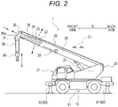
- Fig. 2 is a side view that illustrates a crane according to the first embodiment.
- an actual crane is a crane 1
- a virtual crane is a virtual crane 1A.
- forward and backward directions of the crane 1 are forward and backward directions D.
- a crane information display system 100 As illustrated in Fig. 1 , a crane information display system 100 according to the first embodiment will be described about an example in which a worker M images, with a tablet terminal 50 as a user terminal that includes a camera 51, a work site in which the crane 1 is going to be installed.
- the crane 1 includes a travelling body 10, a rotating body 20, and a boom 30.
- the travelling body 10 includes a vehicle body frame 11, outriggers 80, a travelling device for travelling by itself a road and a work site, and the like.
- the outriggers 80 include rear outriggers 81 attached to rear side surfaces of the vehicle body frame 11 of the travelling body 10, and front outriggers 82 attached to front side surfaces of the vehicle body frame 11.
- the outriggers 80 are accommodated in the vehicle body frame 11 at a time of travelling.
- the outriggers 80 protrude in a horizontal direction and a perpendicular direction at a time of work to lift the whole vehicle body and stabilize the posture.
- the rotating body 20 is provided over the travelling body 10 and can rotate on a vertical axis C1 relative to the travelling body 10.
- the rotating body 20 includes a cabin 21.
- the cabin 21 includes an operation unit for controlling travel of the travelling body 10 (e.g., a steering wheel, a shift lever, an accelerator pedal, a brake pedal, and the like). Further, the cabin 21 includes an operation unit for operating the rotating body 20, the boom 30, a winch, and the like. A worker who has boarded the cabin 21 operates the operation unit to rotate the rotating body 20, raise and lower and extend and contract the boom 30, and turn the winch to perform work.
- the base end side of the boom 30 is supported by the rotating body 20.
- the boom 30 is attached to the rotating body 20 in such a manner that the boom 30 can be raised and lowered relative to the rotating body 20.
- the boom 30 is raised and lowered by a raising and lowering cylinder 22 provided for the rotating body 20, and is extended and contracted by an extending and contracting cylinder (not illustrated).
- the boom 30 includes intermediate booms 32 to 35 between a base end boom 31 on the base end side and a front end boom 36 on the front end side.
- the intermediate booms 32 to 35 and the front end boom 36 are telescopic to be accommodated sequentially in the base end boom 31.
- a sheave 37 is disposed at a boom head 36a provided at the front end of the front end boom 36.
- a wire rope 38 for a hung load is wound around the winch of the rotating body 20 provided near the base end of the boom 30.
- the wire rope 38 is disposed along an axis direction of the boom 30 from the winch to the sheave 37.
- the wire rope 38 wound around the sheave 37 is hung downward in a vertical direction from the sheave 37.
- a hook 39 is provided at a lowest portion of the wire rope 38.
- a load is hung on the hook 39, and the wire rope 38 wound around the winch is let out to lower the hook 39.
- the wire rope 38 is wound up to raise the hook 39.
- the winch lets out and winds up the wire rope 38, the boom 30 is raised, lowered, extended, and contracted, and the rotating body 20 is rotated so that the crane 1 configured as described above moves a load hung from the hook 39 to a predetermined position.
- the tablet terminal 50 includes the camera 51, an image display unit 52, and an input unit 53.
- the image display unit 52 is also configured as a touch panel as the input unit 53.
- a first information display unit 41 (that is to say, a marker) is attached to a support member 45, such as a standing signboard.
- the support member 45 to which the first information display unit 41 is attached is installed in a place in which the crane 1 is going to be installed.
- the first information display unit 41 may be an AprilTag.
- information about the machine type of the crane 1, the shape and size of the first information display unit 41, and information about a predetermined position of the crane 1 are stored.
- the information about the predetermined position of the crane 1 may be the center of the left side surface of the vehicle body frame 11 of the travelling body 10.
- a second information display unit 42 (that is to say, a marker) is installed at a position onto which the crane 1 is going to unload a hung load, e.g., a rooftop of a building B.
- the second information display unit 42 may be an AprilTag.
- the shape and size of the second information display unit 42 are stored.
- the first information display unit 41 and the second information display unit 42 have different display information (that is to say, code information) due to, for example, characters, marks, signs, patterns, or the like provided for the surfaces of the first information display unit 41 and the second information display unit 42.
- the display information (that is to say, code information) that the first information display unit 41 and the second information display unit 42 have respectively can be read from a camera image generated by the camera 51, using a decipherment program preliminarily stored in a control unit 60 (described below), or the like. Further, the first information display unit 41 and the second information display unit 42 can be identified from the display information (that is to say, code information) that the first information display unit 41 and the second information display unit 42 have respectively.
- the shapes and sizes stored in the first information display unit 41 and the second information display unit 42 are, for example, the shapes and sizes obtained when the first information display unit 41 and the second information display unit 42 are imaged from the fronts at a predetermined distance (hereinafter referred to as “reference shapes” and “reference sizes”).
- Fig. 3 is a block diagram that illustrates a functional configuration of the crane information display system 100 according to the first embodiment.
- Fig. 4 is a drawing that illustrates an image displayed on the image display unit 52 according to the first embodiment.
- the functional configuration of the crane information display system 100 according to the first embodiment will be described.
- the crane information display system 100 is such that an image of the first information display unit 41 imaged with the camera 51, an image of the second information display unit 42 imaged with the camera 51, and input information input into the input unit 53 are input into the control unit 60 (in the present embodiment, a control unit incorporated in the tablet terminal 50), and information controlled by the control unit 60 is output on the image display unit 52.
- the control unit 60 in the present embodiment, a control unit incorporated in the tablet terminal 50
- information controlled by the control unit 60 is output on the image display unit 52.
- the camera 51 may be, for example, the camera 51 that the tablet terminal 50 that is common includes.
- the camera 51 can image a work site in which the crane 1 is going to be installed, the first information display unit 41, and the second information display unit 42.
- the length of the boom 30 is the length of the boom 30 in a state in which the front end boom 36 and the intermediate booms 32 to 35 are accommodated in the base end boom 31 (a completely contracted state), the length of the boom 30 in a state in which the front end boom 36 extends, the length of the boom 30 in a state in which the front end boom 36 and the intermediate booms 32 to 35 extend (a completely extending state), or the like.
- the control unit 60 includes a storage unit 61, a crane information acquisition unit 62, a virtual crane generation unit 65, a position/posture calculation unit 66, a position calculation unit 67, and an information processing unit 68.
- the control unit 60 is, for example, a widely-known microcomputer that includes a central processing unit (CPU), random access memory (RAM), read only memory (ROM), and the like.
- control unit 60 (the crane information acquisition unit 62, the virtual crane generation unit 65, the position/posture calculation unit 66, and the position calculation unit 67, and the information processing unit 68) are realized by, for example, the CPU referring to control programs and various data stored in the storage unit 61 (e.g., a hard disk drive (HDD), the ROM, or the RAM).
- storage unit 61 e.g., a hard disk drive (HDD), the ROM, or the RAM.
- the storage unit 61 stores shape information about various types of cranes, and performance information about various types of cranes.
- the performance information includes, for example, information regarding the shapes of the outriggers 80, information regarding possible work area in a horizontal direction and information regarding possible work area in a height direction that correspond to the protrusion amount of the outriggers 80 and the length of the boom 30, information regarding a range of angles by which the boom is raised or lowered, information regarding load ratios, information regarding a tail swing area, and the like.
- the crane information acquisition unit 62 acquires information about the machine type of the crane 1, and acquires, from the storage unit 61, shape information and performance information about the acquired machine type of the crane 1. That is to say, the crane information acquisition unit 62 reads into the first information display unit 41 imaged with the camera 51 (that is to say, reads display information of the first information display unit 41 from the camera image), acquires the machine type of the crane 1, and acquires, from the storage unit 61, shape information and performance information about the acquired machine type.
- the crane information acquisition unit 62 includes a virtual outrigger generation unit 63, and a possible work area calculation unit 64.
- the virtual outrigger generation unit 63 On the basis of information regarding the shapes of the outriggers 80 stored in the storage unit 61 (that is to say, the shapes of the outriggers 80 that correspond to the machine type of the crane 1 specified from display information of an information display unit 40), and a protrusion amount by which the outriggers 80 protrude in a horizontal direction that has been input into the input unit 53, the virtual outrigger generation unit 63 generates three-dimensional data on virtual outriggers 80A, as information about the crane 1.
- the possible work area calculation unit 64 refers to information about the machine type of the crane 1 specified from the display information of the information display unit 40, and calculates possible work area of the crane 1, as information about the crane 1, on the basis of a hung load weight and the length of the boom 30 input into the input unit 53.
- the possible work area calculation unit 64 can calculate possible work area for a plurality of load ratios. In the first embodiment, the possible work area calculation unit 64 calculates a possible work area for a load ratio of 80%, and a possible work area for a load ratio of 100%. Note that the possible work area is an area in which the crane 1 can work in a horizontal direction, in a plane in which the crane 1 is installed.
- the virtual crane generation unit 65 generates three-dimensional data on a virtual crane 1A, on the basis of the information about the crane 1 acquired by the crane information acquisition unit 62.
- the position/posture calculation unit 66 calculates the position and posture of the virtual crane 1A (that is to say, the position at which the virtual crane 1A is to be disposed and the posture to be taken by the virtual crane 1A in the image of the camera 51) on the basis of the first information display unit 41 imaged with the camera 51.
- the position/posture calculation unit 66 acquires information about the posture of the virtual crane 1A, on the basis of the shape of the first information display unit 41 imaged with the camera 51 (hereinafter referred to as an "outline shape of the information display unit 40"), and the reference shape of the first information display unit 41 stored in the first information display unit 41. That is to say, the position/posture calculation unit 66 reads, from an image of the camera 51, display information (that is to say, code information) of the first information display unit 41 to acquire information regarding the reference shape of the first information display unit 41, and extracts, from the image of the camera 51, an outline shape of the first information display unit 41 that appears in the camera 51 by publicly-known pattern matching, or the like.
- display information that is to say, code information
- the position/posture calculation unit 66 compares the outline shape of the first information display unit 41 that appears in the image of the camera 51, with the reference shape of the first information display unit 41 to calculate the position at which the virtual crane 1A is to be disposed and the posture to be taken by the virtual crane 1A in the image of the camera 51.
- the posture is such that the left side surface of the virtual crane 1A is right in front of the camera 51.
- the posture is such that the left side surface of the virtual crane 1A slightly faces left from right in front of the camera 51.
- the posture is such that the left side surface of the virtual crane 1A slightly faces right from right in front of the camera 51.
- the position/posture calculation unit 66 compares the outline shape of the first information display unit 41 imaged with the camera 51, with the reference shape of the first information display unit 41 stored in the first information display unit 41 to acquire information about the posture of the virtual crane 1A.
- the position/posture calculation unit 66 acquires information about the position of the virtual crane 1A, on the basis of the size of the outline shape of the first information display unit 41 imaged with the camera 51, and the reference size of the first information display unit 41 stored in the first information display unit 41. More specifically, the position/posture calculation unit 66 compares the reference size of the first information display unit 41 stored in the first information display unit 41 with the size of the outline shape of the first information display unit 41 imaged with the camera 51 to calculate the distance from the camera 51 to the first information display unit 41.
- the position calculation unit 67 calculates information about a relative position of the second information display unit 42 from the first information display unit 41, on the basis of the second information display unit 42 imaged with the camera 51. More specifically, the position calculation unit 67 reads into the second information display unit 42 imaged with the camera 51 (that is to say, reads, from the image of the camera 51, display information of the second information display unit 42), and calculates the distance and direction from the first information display unit 41, with the position of the first information display unit 41 as the reference. That is to say, the position calculation unit 67 calculates information about the distance of the second information display unit 42 in a horizontal direction, and information about the distance of the second information display unit 42 in a height direction, with the first information display unit 41 as the reference.
- the position calculation unit 67 functions in a state in which the first information display unit 41 and the second information display unit 42 both appear in an image of the camera 51.
- the position calculation unit 67 acquires the reference shape of the second information display unit 42, extracts an outline shape of the second information display unit 42 that appears in an image of the camera 51, and specifies the position of the second information display unit 42 in the image of the camera 51, on the basis of information about the reference shape of the second information display unit 42, and the outline shape of the second information display unit 42.
- the position calculation unit 67 refers to the position of the first information display unit 41 in the image of the camera 51 calculated by the position/posture calculation unit 66, and the position of the second information display unit 42 in the image of the camera 51 calculated by the position calculation unit 67 to calculate information about the relative position of the second information display unit 42 from the first information display unit 41.
- the positional relationship between an image of the camera 51 in which a first information display unit 41 appears and an image of the camera 51 in which a second information display unit 42 appears is specified by simultaneous localization and mapping (SLAM) technology or the like, the function of the position calculation unit 67 can be realized even if the first information display unit 41 and the second information display unit 42 both do not appear in one image.
- SLAM simultaneous localization and mapping
- the information processing unit 68 processes the virtual crane 1A generated by the virtual crane generation unit 65, into information that corresponds to the position and posture of the virtual crane 1A calculated by the position/posture calculation unit 66.
- the information processing unit 68 converts image information about the virtual crane 1A generated by the virtual crane generation unit 65, into image information that corresponds to the position at which the virtual crane 1A is to be disposed and the posture to be taken by the virtual crane 1A in an image of the camera 51 calculated by the position/posture calculation unit 66.
- the information processing unit 68 converts image information about the virtual crane 1A in such a manner that when a position at which the crane is going to be installed (that is to say, a position at which the first information display unit 41 is installed) is seen from the imaging position of the camera 51, a three-dimensional image of the virtual crane 1A becomes an image that simulates a state in which the crane 1 actually exists.
- image processing by the information processing unit 68 is realized by publicly-known coordinate conversion processing or the like.
- the information processing unit 68 processes the performance information about the crane 1 acquired by the crane information acquisition unit 62, the virtual outriggers 80A generated by the virtual outrigger generation unit 63, and the possible work area of the crane 1 calculated by the possible work area calculation unit 64, into information that corresponds to the position and posture of the virtual crane 1A calculated by the position/posture calculation unit 66. That is to say, the information processing unit 68 processes the information about the crane 1 acquired by the crane information acquisition unit 62, into information that corresponds to the position and posture of the virtual crane 1A calculated by the position/posture calculation unit 66.
- the information processing unit 68 processes the information about the crane 1 acquired by the crane information acquisition unit 62, into information that corresponds to the position and posture of the virtual crane 1A calculated by the position/posture calculation unit 66, with the second information display unit 42 as the reference.
- the information processing unit 68 processes the information about the crane 1 that has been made to correspond to the position and posture of the virtual crane 1A calculated by the position/posture calculation unit 66, into information with the second information display unit 42 as the reference.
- the information processing unit 68 converts the information about the crane 1 acquired by the crane information acquisition unit 62 (for example, possible work area 75 and 76 of the crane 1), into three-dimensional image information in which the information about the crane 1 acquired by the crane information acquisition unit 62 (for example, the possible work area 75 and 76 of the crane 1) corresponds to a work position at a time when the crane 1 unloads a hung load.
- the image display unit 52 overlays and displays the information processed by the information processing unit 68 onto an image of the camera 51. More specifically, as illustrated in Fig. 4 , the image display unit 52 superimposes and displays, on an image of a work site imaged with the camera 51 in which the crane 1 is going to be installed, the virtual crane 1A, a tail swing area 73 of the crane 1 acquired by the crane information acquisition unit 62, the virtual outriggers 80A generated by the virtual outrigger generation unit 63, possible work area 71 and 72 in a plane in which the crane 1 is installed that has been calculated by the possible work area calculation unit 64, and possible work area 75 and 76 of the crane 1 at the height at which the second information display unit 42 is disposed. Further, the image display unit 52 displays a hung load weight input into the input unit 53.
- the virtual outriggers 80A include virtual front outriggers 82A and virtual rear outriggers 81A.
- the possible work area in a plane in which the crane 1 is installed include the possible work area 72 for a load ratio of 80%, and the possible work area 71 for a load ratio of 100%.
- the possible work area at the height at which the second information display unit 42 is disposed include the possible work area 76 for a load ratio of 80%, and the possible work area 75 for a load ratio of 100%.
- the image display unit 52 displays the virtual crane 1A, the possible work area 71 and 72 (75 and 76) of the crane 1, the virtual outriggers 80A, and the tail swing area 73 of the crane 1 in a three-dimensional image in such manner that the virtual crane 1A, the possible work area 71 and 72 (75 and 76) of the crane 1, the virtual outriggers 80A, and the tail swing area 73 of the crane 1 are overlaid onto a surrounding environment that appears in an image of the camera 51.
- the image display unit 52 displays the virtual outriggers 80A at, for example, the positions of outriggers of the virtual crane 1A in an image of the camera 51. Further, the image display unit 52 displays the possible work area 71 and 72 of the crane 1 around the virtual crane 1A as the center, in an image of the camera 51, for example. Further, the image display unit 52 displays the tail swing area 73 of the crane 1 around a rotation mount of the virtual crane 1A as the center, in an image of the camera 51, for example.
- Fig. 5 is a flowchart that illustrates a process of processing by the control unit 60 of the crane information display system 100 according to the first embodiment.
- the process of processing by the control unit 60 of the crane information display system 100 according to the first embodiment will be described.
- the crane information acquisition unit 62 reads into the first information display unit 41 imaged with the camera 51, as illustrated in Fig. 5 (step S101).
- the crane information acquisition unit 62 acquires, from the storage unit 61, shape information and performance information about the machine type of the crane 1 that has been acquired (step S102).
- the virtual crane generation unit 65 generates three-dimensional data on virtual outriggers, on the basis of information about the crane 1 acquired by the crane information acquisition unit 62 (step S103).
- the position/posture calculation unit 66 calculates the position and posture of a virtual crane 1A, on the basis of the first information display unit 41 imaged with the camera 51 (step S104).
- control unit 60 determines whether or not a protrusion amount of the outriggers 80 has been input into the input unit 53 (step S105). If it is determined that a protrusion amount of the outriggers 80 has been input into the input unit 53 (YES in step S105), the virtual outrigger generation unit 63 generates virtual outriggers 80A (step S106), and the processing proceeds to step S107. On the other hand, if a protrusion amount of the outriggers 80 has not been input into the input unit 53, (NO in step S105), the processing proceeds to step S107.
- control unit 60 determines whether or not a hung load weight and the length of the boom 30 have been input into the input unit 53 (step S107). If it is determined that a hung load weight and the length of the boom 30 have been input into the input unit 53 (YES in step S107), the possible work area calculation unit 64 calculates possible work area 71 and 72 (step S108), and the processing proceeds to step 109. On the other hand, if it is determined that a hung load weight and the length of the boom 30 have not been input into the input unit 53 (NO in step S108), the processing proceeds to step S109.
- the information processing unit 68 processes the virtual outriggers 80A generated by the virtual outrigger generation unit 63, and the information about the crane 1 acquired by the crane information acquisition unit 62, into information that corresponds to the position and posture of the crane 1 calculated by the position/posture calculation unit 66 (step S109).
- the position calculation unit 67 reads into the second information display unit 42 imaged with the camera 51 (step S110).
- the position calculation unit 67 calculates position information about the second information display unit 42 from the first information display unit 41 (step Sill).
- the information processing unit 68 processes the information about the crane 1 acquired by the crane information acquisition unit 62, into information that corresponds to the position and posture of the virtual crane 1A calculated by the position/posture calculation unit 66, with the second information display unit 42 as the reference (step S112).
- the image display unit 52 superimposes and displays, on an image of a work site imaged with the camera 51 in which the crane 1 is going to be installed, the virtual crane 1A, a tail swing area 73 of the crane 1 acquired by the crane information acquisition unit 62, the virtual outriggers 80A generated by the virtual outrigger generation unit 63, possible work area 71 and 72 in a plane in which the virtual crane 1A is installed, and possible work area 75 and 76 at the height at which the second information display unit 42 is disposed (step S113), and the processing is ended.
- the crane 1 is carried and installed in such a manner that a predetermined position of the actual crane 1 (e.g., the center of the left side surface of the vehicle body frame 11 of the travelling body 10) is made to correspond to the first information display unit 41 attached to the support member 45 put in the work site.
- a predetermined position of the actual crane 1 e.g., the center of the left side surface of the vehicle body frame 11 of the travelling body
- the crane information display system 100 includes the crane information acquisition unit 62 that images, with the camera 51, the first information display unit 41 that displays information about the crane 1 to acquire the information about the crane 1, the virtual crane generation unit 65 that generates a virtual crane 1A of the crane 1 that is three-dimensional, on the basis of the information about the crane 1 acquired by the crane information acquisition unit 62, the position/posture calculation unit 66 that calculates the position and posture of the virtual crane 1A, on the basis of the first information display unit 41 imaged with the camera 51, the information processing unit 68 that processes the virtual crane 1A generated by the virtual crane generation unit 65, into information that corresponds to the position and posture of the virtual crane 1A calculated by the position/posture calculation unit 66, and the image display unit 52 that overlays and displays the information processed by the information processing unit 68 onto the image imaged with the camera 51 ( Figs. 3 and 4 ).
- the virtual crane 1A can be disposed and displayed in a scenery image of a place in which the crane 1 is going to be installed. Therefore, disposition of the crane 1 can be examined in a three-dimensional image without actually disposing the crane 1 in a place in which the crane 1 is going to be installed. As a result, a work plan of the crane 1 can be easily examined.
- the information processing unit 68 processes information about the crane 1 acquired by the crane information acquisition unit 62, into information that corresponds to the position and posture of a virtual crane 1A calculated by the position/posture calculation unit 66 ( Figs. 3 and 4 ).
- the information about the crane 1 can be overlaid and displayed onto an image in which the virtual crane 1A is disposed. Therefore, the virtual crane 1A, a site environment around the virtual crane 1A, and the information about the crane 1 can be checked in a three-dimensional image in real time. As a result, a work plan of the crane 1 can be easily examined without disposing the actual crane 1 in a place in which the crane 1 is going to be installed.
- the second information display unit 42 is provided and disposed at a position onto which the crane 1 unloads a hung load, the second information display unit 42 is imaged with the camera 51, the position calculation unit 67 calculates position information about the second information display unit 42 from the first information display unit 41, and the information processing unit 68 processes, on the basis of the position information calculated by the position calculation unit 67, information about the crane 1 acquired by the crane information acquisition unit 62, into information that corresponds to the position and posture of a virtual crane 1A calculated by the position/posture calculation unit 66, with the second information display unit 42 as the reference ( Figs. 3 and 4 ).
- possible work area 75 and 76 at the height at which the second information display unit 42 is installed can be displayed. Therefore, for example, if work that unloads a hung load is performed at a high position, such as a rooftop of a building B, as illustrated in Fig. 4 , possible work area 75 and 76 of the crane 1 at the height at which the second information display unit 42 is installed can be displayed. As a result, even if a position onto which a hung load is unloaded is at a height different from the height of a plane in which the crane 1 is installed, a work plan of the crane 1 can be easily examined.
- the input unit 53 into which a protrusion amount of the outriggers 80 of a virtual crane 1A is input is provided, and the crane information acquisition unit 62 includes the virtual outrigger generation unit 63 that generates three-dimensional virtual outriggers 80A, on the basis of the input value input into the input unit 53 ( Figs. 3 and 4 ).
- the virtual outriggers 80A of a protrusion amount that corresponds to the input value can be overlaid and displayed onto an image in which the virtual crane 1A disposed in a place in which the crane 1 is going to be installed, and the surroundings around the virtual crane 1A are imaged. Therefore, a protrusion amount of the outriggers 80 can be checked in a three-dimensional image in real time in the work site.
- the input unit 53 into which a hung load weight and the length of the boom 30 of the crane 1 are input is provided, and the crane information acquisition unit 62 includes the possible work area calculation unit 64 that calculates possible work area 71 and 72 of the crane 1, on the basis of the input values input into the input unit 53 ( Figs. 3 and 4 ).
- the possible work area 71 and 72 for a predetermined hung load weight can be overlaid and displayed, on the basis of the length of the boom 30, onto an image in which a virtual crane 1A disposed in a place in which the crane 1 is going to be installed and the surroundings around the virtual crane 1A are imaged. Therefore, the possible work area 71 and 72 can be checked in a three-dimensional image in real time in the work site.
- information about the crane 1 includes a tail swing area 73 of the crane 1 ( Figs. 3 and 4 ).
- the tail swing area 73 can be overlaid and displayed onto an image in which a virtual crane 1A disposed in a place in which the crane 1 is going to be installed and the surroundings around the virtual crane 1A are imaged. Therefore, the tail swing area 73 can be checked in a three-dimensional image in real time in the work site.
- information about a predetermined position of the crane 1 stored in the first information display unit 41 is the center of the left side surface of the vehicle body frame 11 of the travelling body 10.
- information about a predetermined position of the crane 1 stored in the first information display unit 41 is not limited to the center of the left side surface of the vehicle body frame 11.
- the front surface, the back surface, and the right side surface of the vehicle body frame 11 may be stored as information about predetermined positions of the crane 1 stored in the first information display unit 41, and a worker M may appropriately perform the selection with the input unit 53.
- the first information display unit 41 In the first embodiment, an example is shown in which information about the machine type of the one crane 1 is stored in the first information display unit 41. However, information about a plurality of machine types of cranes may be stored in the first information display unit 41, and a worker M may appropriately perform the selection with the input unit 53.
- an information display unit 40 is an AprilTag.
- an information display unit is not limited to the aspect, but may be, for example, a two-dimensional code, such as a QR code (registered trademark).
- an information display unit may be a crane itself, and information about the crane may be acquired by image recognition using deep learning.
- the possible work area 72 and 76 for a load ratio of 80%, and the possible work area 71 and 75 for a load ratio of 100% are displayed on the image display unit 52.
- one possible work area may be displayed, or three or more possible work area may be displayed on an image display unit.
- load ratios of possible work area are not limited to 80% and 100%.
- a user terminal is the tablet terminal 50 that includes the camera 51, the input unit 53, and the image display unit 52.
- the user terminal may be a smartphone.
- the user terminal may include a camera and an image display unit that are separate.
- shape information and performance information of the crane 1 are stored in the storage unit 61.
- shape information and performance information of a crane may be stored in the first information display unit.
Landscapes
- Engineering & Computer Science (AREA)
- Mechanical Engineering (AREA)
- Automation & Control Theory (AREA)
- Jib Cranes (AREA)
- Structures For Mounting Electric Components On Printed Circuit Boards (AREA)
- Lead Frames For Integrated Circuits (AREA)
- Processing Or Creating Images (AREA)
Abstract
Description
- The present invention relates to a crane information display system.
- Crane information display systems that display information about the cranes have been known (e.g., refer to Patent Literature 1).
-
Patent Literature 1 discloses a configuration that displays an operation state of a crane to an operator, and displays an operation state of a crane to a person outside the crane with a mobile terminal. Consequently, a person outside the crane can grasp an operation state of the crane. - Patent Literature 1:
JP 2014-227281 A - However, the configuration described in
Patent Literature 1 simply displays an operation state of an actual crane, and has a problem that a work plan of the crane cannot be made without disposing the crane in a place in which the crane is going to be installed. - It is therefore an object of the present invention to provide a crane information display system that can make a work plan of a crane without disposing the crane in a place in which the crane is going to be installed.
- A main present disclosure that solves the problems described above is
a crane information display system that includes a terminal device having a camera, and obtains a camera image by imaging, with the camera, a first information display unit that displays information about a crane, the crane information display system including: - a crane information acquisition unit that reads, from the camera image, display information of the first information display unit to acquire information about the crane;
- a virtual crane generation unit that generates, on the basis of the information about the crane acquired by the crane information acquisition unit, image information about a virtual crane that corresponds to a three-dimensional image of the crane;
- a position/posture calculation unit that reads, from the camera image, the display information of the first information display unit to acquire information about a reference shape of the first information display unit, and extracts, from the camera image, information about an outline shape of the first information display unit that appears in the camera image, and calculates, on the basis of the reference shape of the first information display unit and the information about the outline shape of the first information display unit, a position at which the virtual crane is to be disposed and a posture to be taken by the virtual crane in the camera image;
- an information processing unit that converts the image information about the virtual crane generated by the virtual crane generation unit, into image information that corresponds to the position and the posture of the virtual crane calculated by the position/posture calculation unit; and
- an image display unit that overlays and displays, onto the camera image, the virtual crane to which the processing by the information processing unit that converts the image information has been applied.
- The crane information display system according to the present invention configured as described above can make a work plan of the crane without disposing the crane in a place in which the crane is going to be installed.
-
-
Fig. 1 is a drawing that illustrates a crane information display system according to a first embodiment. -
Fig. 2 is a side view that illustrates a crane according to the first embodiment. -
Fig. 3 is a block diagram that illustrates a functional configuration of the crane information display system according to the first embodiment. -
Fig. 4 is a drawing that illustrates an image displayed on an image display unit according to the first embodiment. -
Fig. 5 is a flowchart that illustrates a process of processing by a control unit of the crane information display system according to the first embodiment. - Hereinafter, an embodiment that realizes a crane information display system according to the present invention will be described on the basis of a first embodiment illustrated in the drawings.
-
Fig. 1 is a drawing that illustrates a crane information display system according to a first embodiment.Fig. 2 is a side view that illustrates a crane according to the first embodiment. Hereinafter, the configuration of the crane information display system according to the first embodiment will be described. Note that an actual crane is acrane 1, and a virtual crane is avirtual crane 1A. Further, forward and backward directions of thecrane 1 are forward and backward directions D. - As illustrated in
Fig. 1 , a craneinformation display system 100 according to the first embodiment will be described about an example in which a worker M images, with atablet terminal 50 as a user terminal that includes acamera 51, a work site in which thecrane 1 is going to be installed. - As illustrated in
Fig. 2 , thecrane 1 includes atravelling body 10, a rotatingbody 20, and aboom 30. - The
travelling body 10 includes avehicle body frame 11,outriggers 80, a travelling device for travelling by itself a road and a work site, and the like. - The
outriggers 80 includerear outriggers 81 attached to rear side surfaces of thevehicle body frame 11 of thetravelling body 10, andfront outriggers 82 attached to front side surfaces of thevehicle body frame 11. Theoutriggers 80 are accommodated in thevehicle body frame 11 at a time of travelling. On the other hand, theoutriggers 80 protrude in a horizontal direction and a perpendicular direction at a time of work to lift the whole vehicle body and stabilize the posture. - The rotating
body 20 is provided over thetravelling body 10 and can rotate on a vertical axis C1 relative to thetravelling body 10. The rotatingbody 20 includes acabin 21. Thecabin 21 includes an operation unit for controlling travel of the travelling body 10 (e.g., a steering wheel, a shift lever, an accelerator pedal, a brake pedal, and the like). Further, thecabin 21 includes an operation unit for operating the rotatingbody 20, theboom 30, a winch, and the like. A worker who has boarded thecabin 21 operates the operation unit to rotate the rotatingbody 20, raise and lower and extend and contract theboom 30, and turn the winch to perform work. - The base end side of the
boom 30 is supported by therotating body 20. Theboom 30 is attached to therotating body 20 in such a manner that theboom 30 can be raised and lowered relative to the rotatingbody 20. Theboom 30 is raised and lowered by a raising and loweringcylinder 22 provided for therotating body 20, and is extended and contracted by an extending and contracting cylinder (not illustrated). - The
boom 30 includesintermediate booms 32 to 35 between abase end boom 31 on the base end side and afront end boom 36 on the front end side. Theintermediate booms 32 to 35 and thefront end boom 36 are telescopic to be accommodated sequentially in thebase end boom 31. - A sheave 37 is disposed at a
boom head 36a provided at the front end of thefront end boom 36. Awire rope 38 for a hung load is wound around the winch of the rotatingbody 20 provided near the base end of theboom 30. Thewire rope 38 is disposed along an axis direction of theboom 30 from the winch to the sheave 37. Thewire rope 38 wound around the sheave 37 is hung downward in a vertical direction from the sheave 37. Ahook 39 is provided at a lowest portion of thewire rope 38. - A load is hung on the
hook 39, and thewire rope 38 wound around the winch is let out to lower thehook 39. Thewire rope 38 is wound up to raise thehook 39. - The winch lets out and winds up the
wire rope 38, theboom 30 is raised, lowered, extended, and contracted, and the rotatingbody 20 is rotated so that thecrane 1 configured as described above moves a load hung from thehook 39 to a predetermined position. - As illustrated in
Fig. 1 , thetablet terminal 50 includes thecamera 51, animage display unit 52, and aninput unit 53. - An image imaged with the
camera 51 is displayed on theimage display unit 52. Theimage display unit 52 is also configured as a touch panel as theinput unit 53. - As illustrated in
Fig. 1 , a first information display unit 41 (that is to say, a marker) is attached to asupport member 45, such as a standing signboard. Thesupport member 45 to which the firstinformation display unit 41 is attached is installed in a place in which thecrane 1 is going to be installed. - The first
information display unit 41 may be an AprilTag. In the firstinformation display unit 41, information about the machine type of thecrane 1, the shape and size of the firstinformation display unit 41, and information about a predetermined position of thecrane 1 are stored. The information about the predetermined position of thecrane 1 may be the center of the left side surface of thevehicle body frame 11 of the travellingbody 10. - As illustrated in
Fig. 1 , a second information display unit 42 (that is to say, a marker) is installed at a position onto which thecrane 1 is going to unload a hung load, e.g., a rooftop of a building B. The secondinformation display unit 42 may be an AprilTag. In the secondinformation display unit 42, the shape and size of the secondinformation display unit 42 are stored. The firstinformation display unit 41 and the secondinformation display unit 42 have different display information (that is to say, code information) due to, for example, characters, marks, signs, patterns, or the like provided for the surfaces of the firstinformation display unit 41 and the secondinformation display unit 42. - The display information (that is to say, code information) that the first
information display unit 41 and the secondinformation display unit 42 have respectively can be read from a camera image generated by thecamera 51, using a decipherment program preliminarily stored in a control unit 60 (described below), or the like. Further, the firstinformation display unit 41 and the secondinformation display unit 42 can be identified from the display information (that is to say, code information) that the firstinformation display unit 41 and the secondinformation display unit 42 have respectively. Note that the shapes and sizes stored in the firstinformation display unit 41 and the secondinformation display unit 42 are, for example, the shapes and sizes obtained when the firstinformation display unit 41 and the secondinformation display unit 42 are imaged from the fronts at a predetermined distance (hereinafter referred to as "reference shapes" and "reference sizes"). -
Fig. 3 is a block diagram that illustrates a functional configuration of the craneinformation display system 100 according to the first embodiment.Fig. 4 is a drawing that illustrates an image displayed on theimage display unit 52 according to the first embodiment. Hereinafter, the functional configuration of the craneinformation display system 100 according to the first embodiment will be described. - As illustrated in
Fig. 3 , the craneinformation display system 100 is such that an image of the firstinformation display unit 41 imaged with thecamera 51, an image of the secondinformation display unit 42 imaged with thecamera 51, and input information input into theinput unit 53 are input into the control unit 60 (in the present embodiment, a control unit incorporated in the tablet terminal 50), and information controlled by thecontrol unit 60 is output on theimage display unit 52. - The
camera 51 may be, for example, thecamera 51 that thetablet terminal 50 that is common includes. Thecamera 51 can image a work site in which thecrane 1 is going to be installed, the firstinformation display unit 41, and the secondinformation display unit 42. - A protrusion amount by which the
outriggers 80 protrude in a horizontal direction, a hung load weight, the length of theboom 30, and the like can be input into theinput unit 53. The length of theboom 30 is the length of theboom 30 in a state in which thefront end boom 36 and theintermediate booms 32 to 35 are accommodated in the base end boom 31 (a completely contracted state), the length of theboom 30 in a state in which thefront end boom 36 extends, the length of theboom 30 in a state in which thefront end boom 36 and theintermediate booms 32 to 35 extend (a completely extending state), or the like. - The
control unit 60 includes astorage unit 61, a craneinformation acquisition unit 62, a virtualcrane generation unit 65, a position/posture calculation unit 66, aposition calculation unit 67, and aninformation processing unit 68. Note that thecontrol unit 60 is, for example, a widely-known microcomputer that includes a central processing unit (CPU), random access memory (RAM), read only memory (ROM), and the like. The functions of the control unit 60 (the craneinformation acquisition unit 62, the virtualcrane generation unit 65, the position/posture calculation unit 66, and theposition calculation unit 67, and the information processing unit 68) are realized by, for example, the CPU referring to control programs and various data stored in the storage unit 61 (e.g., a hard disk drive (HDD), the ROM, or the RAM). - The
storage unit 61 stores shape information about various types of cranes, and performance information about various types of cranes. The performance information includes, for example, information regarding the shapes of theoutriggers 80, information regarding possible work area in a horizontal direction and information regarding possible work area in a height direction that correspond to the protrusion amount of theoutriggers 80 and the length of theboom 30, information regarding a range of angles by which the boom is raised or lowered, information regarding load ratios, information regarding a tail swing area, and the like. - On the basis of the first
information display unit 41 imaged with thecamera 51, the craneinformation acquisition unit 62 acquires information about the machine type of thecrane 1, and acquires, from thestorage unit 61, shape information and performance information about the acquired machine type of thecrane 1. That is to say, the craneinformation acquisition unit 62 reads into the firstinformation display unit 41 imaged with the camera 51 (that is to say, reads display information of the firstinformation display unit 41 from the camera image), acquires the machine type of thecrane 1, and acquires, from thestorage unit 61, shape information and performance information about the acquired machine type. - The crane
information acquisition unit 62 includes a virtualoutrigger generation unit 63, and a possible workarea calculation unit 64. - On the basis of information regarding the shapes of the
outriggers 80 stored in the storage unit 61 (that is to say, the shapes of theoutriggers 80 that correspond to the machine type of thecrane 1 specified from display information of an information display unit 40), and a protrusion amount by which theoutriggers 80 protrude in a horizontal direction that has been input into theinput unit 53, the virtualoutrigger generation unit 63 generates three-dimensional data onvirtual outriggers 80A, as information about thecrane 1. - The possible work
area calculation unit 64 refers to information about the machine type of thecrane 1 specified from the display information of the information display unit 40, and calculates possible work area of thecrane 1, as information about thecrane 1, on the basis of a hung load weight and the length of theboom 30 input into theinput unit 53. The possible workarea calculation unit 64 can calculate possible work area for a plurality of load ratios. In the first embodiment, the possible workarea calculation unit 64 calculates a possible work area for a load ratio of 80%, and a possible work area for a load ratio of 100%. Note that the possible work area is an area in which thecrane 1 can work in a horizontal direction, in a plane in which thecrane 1 is installed. - The virtual
crane generation unit 65 generates three-dimensional data on avirtual crane 1A, on the basis of the information about thecrane 1 acquired by the craneinformation acquisition unit 62. - The position/
posture calculation unit 66 calculates the position and posture of thevirtual crane 1A (that is to say, the position at which thevirtual crane 1A is to be disposed and the posture to be taken by thevirtual crane 1A in the image of the camera 51) on the basis of the firstinformation display unit 41 imaged with thecamera 51. - More specifically, the position/
posture calculation unit 66 acquires information about the posture of thevirtual crane 1A, on the basis of the shape of the firstinformation display unit 41 imaged with the camera 51 (hereinafter referred to as an "outline shape of the information display unit 40"), and the reference shape of the firstinformation display unit 41 stored in the firstinformation display unit 41. That is to say, the position/posture calculation unit 66 reads, from an image of thecamera 51, display information (that is to say, code information) of the firstinformation display unit 41 to acquire information regarding the reference shape of the firstinformation display unit 41, and extracts, from the image of thecamera 51, an outline shape of the firstinformation display unit 41 that appears in thecamera 51 by publicly-known pattern matching, or the like. Then the position/posture calculation unit 66 compares the outline shape of the firstinformation display unit 41 that appears in the image of thecamera 51, with the reference shape of the firstinformation display unit 41 to calculate the position at which thevirtual crane 1A is to be disposed and the posture to be taken by thevirtual crane 1A in the image of thecamera 51. - For example, if the shape of the first
information display unit 41 imaged with thecamera 51 is a rectangular shape stored in the first information display unit 41 (that is to say, if the outline shape of the firstinformation display unit 41 that appears in the image of thecamera 51 and the reference shape of the firstinformation display unit 41 specified from the display information of the firstinformation display unit 41 are both a rectangular shape), the posture is such that the left side surface of thevirtual crane 1A is right in front of thecamera 51. For example, if the shape of the firstinformation display unit 41 imaged with thecamera 51 is not a rectangular shape stored in the firstinformation display unit 41 but is a trapezoid such that the left edge of the information display unit 40 is longer (higher) than the right edge (that is to say, if the outline shape of the firstinformation display unit 41 that appears in the image of thecamera 51 is a trapezoid that has a left edge longer than the right edge, and the reference shape of the firstinformation display unit 41 specified from the display information of the firstinformation display unit 41 is a rectangular shape), the posture is such that the left side surface of thevirtual crane 1A slightly faces left from right in front of thecamera 51. If the firstinformation display unit 41 imaged with thecamera 51 does not have a rectangular shape stored in the firstinformation display unit 41 but is trapezoidal such that the right edge of the firstinformation display unit 41 is longer than the left edge (that is to say, if the outline shape of the firstinformation display unit 41 that appears in the image of thecamera 51 is a trapezoid that has a right edge longer than the left edge, and the reference shape of the firstinformation display unit 41 specified from the display information of the firstinformation display unit 41 is a rectangular shape), the posture is such that the left side surface of thevirtual crane 1A slightly faces right from right in front of thecamera 51. - That is to say, the position/
posture calculation unit 66 compares the outline shape of the firstinformation display unit 41 imaged with thecamera 51, with the reference shape of the firstinformation display unit 41 stored in the firstinformation display unit 41 to acquire information about the posture of thevirtual crane 1A. - Further, the position/
posture calculation unit 66 acquires information about the position of thevirtual crane 1A, on the basis of the size of the outline shape of the firstinformation display unit 41 imaged with thecamera 51, and the reference size of the firstinformation display unit 41 stored in the firstinformation display unit 41. More specifically, the position/posture calculation unit 66 compares the reference size of the firstinformation display unit 41 stored in the firstinformation display unit 41 with the size of the outline shape of the firstinformation display unit 41 imaged with thecamera 51 to calculate the distance from thecamera 51 to the firstinformation display unit 41. - The
position calculation unit 67 calculates information about a relative position of the secondinformation display unit 42 from the firstinformation display unit 41, on the basis of the secondinformation display unit 42 imaged with thecamera 51. More specifically, theposition calculation unit 67 reads into the secondinformation display unit 42 imaged with the camera 51 (that is to say, reads, from the image of thecamera 51, display information of the second information display unit 42), and calculates the distance and direction from the firstinformation display unit 41, with the position of the firstinformation display unit 41 as the reference. That is to say, theposition calculation unit 67 calculates information about the distance of the secondinformation display unit 42 in a horizontal direction, and information about the distance of the secondinformation display unit 42 in a height direction, with the firstinformation display unit 41 as the reference. - More specifically, the
position calculation unit 67 functions in a state in which the firstinformation display unit 41 and the secondinformation display unit 42 both appear in an image of thecamera 51. For example, theposition calculation unit 67 acquires the reference shape of the secondinformation display unit 42, extracts an outline shape of the secondinformation display unit 42 that appears in an image of thecamera 51, and specifies the position of the secondinformation display unit 42 in the image of thecamera 51, on the basis of information about the reference shape of the secondinformation display unit 42, and the outline shape of the secondinformation display unit 42. Then theposition calculation unit 67 refers to the position of the firstinformation display unit 41 in the image of thecamera 51 calculated by the position/posture calculation unit 66, and the position of the secondinformation display unit 42 in the image of thecamera 51 calculated by theposition calculation unit 67 to calculate information about the relative position of the secondinformation display unit 42 from the firstinformation display unit 41. However, if the positional relationship between an image of thecamera 51 in which a firstinformation display unit 41 appears and an image of thecamera 51 in which a secondinformation display unit 42 appears is specified by simultaneous localization and mapping (SLAM) technology or the like, the function of theposition calculation unit 67 can be realized even if the firstinformation display unit 41 and the secondinformation display unit 42 both do not appear in one image. - The
information processing unit 68 processes thevirtual crane 1A generated by the virtualcrane generation unit 65, into information that corresponds to the position and posture of thevirtual crane 1A calculated by the position/posture calculation unit 66. In other words, theinformation processing unit 68 converts image information about thevirtual crane 1A generated by the virtualcrane generation unit 65, into image information that corresponds to the position at which thevirtual crane 1A is to be disposed and the posture to be taken by thevirtual crane 1A in an image of thecamera 51 calculated by the position/posture calculation unit 66. For example, theinformation processing unit 68 converts image information about thevirtual crane 1A in such a manner that when a position at which the crane is going to be installed (that is to say, a position at which the firstinformation display unit 41 is installed) is seen from the imaging position of thecamera 51, a three-dimensional image of thevirtual crane 1A becomes an image that simulates a state in which thecrane 1 actually exists. Note that such image processing by theinformation processing unit 68 is realized by publicly-known coordinate conversion processing or the like. - Further, the
information processing unit 68 processes the performance information about thecrane 1 acquired by the craneinformation acquisition unit 62, thevirtual outriggers 80A generated by the virtualoutrigger generation unit 63, and the possible work area of thecrane 1 calculated by the possible workarea calculation unit 64, into information that corresponds to the position and posture of thevirtual crane 1A calculated by the position/posture calculation unit 66. That is to say, theinformation processing unit 68 processes the information about thecrane 1 acquired by the craneinformation acquisition unit 62, into information that corresponds to the position and posture of thevirtual crane 1A calculated by the position/posture calculation unit 66. - Further, on the basis of the position information calculated by the
position calculation unit 67, theinformation processing unit 68 processes the information about thecrane 1 acquired by the craneinformation acquisition unit 62, into information that corresponds to the position and posture of thevirtual crane 1A calculated by the position/posture calculation unit 66, with the secondinformation display unit 42 as the reference. In other words, theinformation processing unit 68 processes the information about thecrane 1 that has been made to correspond to the position and posture of thevirtual crane 1A calculated by the position/posture calculation unit 66, into information with the secondinformation display unit 42 as the reference. That is to say, on the basis of the relative position of the secondinformation display unit 42 from the firstinformation display unit 41 calculated by theposition calculation unit 67, theinformation processing unit 68 converts the information about thecrane 1 acquired by the crane information acquisition unit 62 (for example,possible work area crane 1 acquired by the crane information acquisition unit 62 (for example, thepossible work area crane 1 unloads a hung load. - The
image display unit 52 overlays and displays the information processed by theinformation processing unit 68 onto an image of thecamera 51. More specifically, as illustrated inFig. 4 , theimage display unit 52 superimposes and displays, on an image of a work site imaged with thecamera 51 in which thecrane 1 is going to be installed, thevirtual crane 1A, atail swing area 73 of thecrane 1 acquired by the craneinformation acquisition unit 62, thevirtual outriggers 80A generated by the virtualoutrigger generation unit 63,possible work area crane 1 is installed that has been calculated by the possible workarea calculation unit 64, andpossible work area crane 1 at the height at which the secondinformation display unit 42 is disposed. Further, theimage display unit 52 displays a hung load weight input into theinput unit 53. - The
virtual outriggers 80A include virtualfront outriggers 82A and virtualrear outriggers 81A. The possible work area in a plane in which thecrane 1 is installed include thepossible work area 72 for a load ratio of 80%, and thepossible work area 71 for a load ratio of 100%. The possible work area at the height at which the secondinformation display unit 42 is disposed include thepossible work area 76 for a load ratio of 80%, and thepossible work area 75 for a load ratio of 100%. - That is to say, to allow a three-dimensional examination on how each portion of the
crane 1 affects a site environment when a user actually operates thecrane 1 in the site, theimage display unit 52 displays thevirtual crane 1A, thepossible work area 71 and 72 (75 and 76) of thecrane 1, thevirtual outriggers 80A, and thetail swing area 73 of thecrane 1 in a three-dimensional image in such manner that thevirtual crane 1A, thepossible work area 71 and 72 (75 and 76) of thecrane 1, thevirtual outriggers 80A, and thetail swing area 73 of thecrane 1 are overlaid onto a surrounding environment that appears in an image of thecamera 51. Note that theimage display unit 52 displays thevirtual outriggers 80A at, for example, the positions of outriggers of thevirtual crane 1A in an image of thecamera 51. Further, theimage display unit 52 displays thepossible work area crane 1 around thevirtual crane 1A as the center, in an image of thecamera 51, for example. Further, theimage display unit 52 displays thetail swing area 73 of thecrane 1 around a rotation mount of thevirtual crane 1A as the center, in an image of thecamera 51, for example. -
Fig. 5 is a flowchart that illustrates a process of processing by thecontrol unit 60 of the craneinformation display system 100 according to the first embodiment. Hereinafter, the process of processing by thecontrol unit 60 of the craneinformation display system 100 according to the first embodiment will be described. - When a worker M images, with the
camera 51 attached to thetablet terminal 50, the firstinformation display unit 41 attached to thesupport member 45 installed in a work site in which thecrane 1 is going to be installed, and a site environment around the firstinformation display unit 41, the craneinformation acquisition unit 62 reads into the firstinformation display unit 41 imaged with thecamera 51, as illustrated inFig. 5 (step S101). - Next, the crane
information acquisition unit 62 acquires, from thestorage unit 61, shape information and performance information about the machine type of thecrane 1 that has been acquired (step S102). - Next, the virtual
crane generation unit 65 generates three-dimensional data on virtual outriggers, on the basis of information about thecrane 1 acquired by the crane information acquisition unit 62 (step S103). - Next, the position/
posture calculation unit 66 calculates the position and posture of avirtual crane 1A, on the basis of the firstinformation display unit 41 imaged with the camera 51 (step S104). - Next, the
control unit 60 determines whether or not a protrusion amount of theoutriggers 80 has been input into the input unit 53 (step S105). If it is determined that a protrusion amount of theoutriggers 80 has been input into the input unit 53 (YES in step S105), the virtualoutrigger generation unit 63 generatesvirtual outriggers 80A (step S106), and the processing proceeds to step S107. On the other hand, if a protrusion amount of theoutriggers 80 has not been input into theinput unit 53, (NO in step S105), the processing proceeds to step S107. - Next, the
control unit 60 determines whether or not a hung load weight and the length of theboom 30 have been input into the input unit 53 (step S107). If it is determined that a hung load weight and the length of theboom 30 have been input into the input unit 53 (YES in step S107), the possible workarea calculation unit 64 calculatespossible work area 71 and 72 (step S108), and the processing proceeds to step 109. On the other hand, if it is determined that a hung load weight and the length of theboom 30 have not been input into the input unit 53 (NO in step S108), the processing proceeds to step S109. - Further, the
information processing unit 68 processes thevirtual outriggers 80A generated by the virtualoutrigger generation unit 63, and the information about thecrane 1 acquired by the craneinformation acquisition unit 62, into information that corresponds to the position and posture of thecrane 1 calculated by the position/posture calculation unit 66 (step S109). - Next, the
position calculation unit 67 reads into the secondinformation display unit 42 imaged with the camera 51 (step S110). - Next, the
position calculation unit 67 calculates position information about the secondinformation display unit 42 from the first information display unit 41 (step Sill). - Next, on the basis of the position information calculated by the
position calculation unit 67, theinformation processing unit 68 processes the information about thecrane 1 acquired by the craneinformation acquisition unit 62, into information that corresponds to the position and posture of thevirtual crane 1A calculated by the position/posture calculation unit 66, with the secondinformation display unit 42 as the reference (step S112). - Next, the
image display unit 52 superimposes and displays, on an image of a work site imaged with thecamera 51 in which thecrane 1 is going to be installed, thevirtual crane 1A, atail swing area 73 of thecrane 1 acquired by the craneinformation acquisition unit 62, thevirtual outriggers 80A generated by the virtualoutrigger generation unit 63,possible work area virtual crane 1A is installed, andpossible work area information display unit 42 is disposed (step S113), and the processing is ended. - If an installation place of the
crane 1 is examined, and the installation place of thecrane 1 is determined in this way, thecrane 1 is carried and installed in such a manner that a predetermined position of the actual crane 1 (e.g., the center of the left side surface of thevehicle body frame 11 of the travelling body 10) is made to correspond to the firstinformation display unit 41 attached to thesupport member 45 put in the work site. - Hereinafter, effects of the crane
information display system 100 according to the first embodiment will be described. - The crane
information display system 100 according to the first embodiment includes the craneinformation acquisition unit 62 that images, with thecamera 51, the firstinformation display unit 41 that displays information about thecrane 1 to acquire the information about thecrane 1, the virtualcrane generation unit 65 that generates avirtual crane 1A of thecrane 1 that is three-dimensional, on the basis of the information about thecrane 1 acquired by the craneinformation acquisition unit 62, the position/posture calculation unit 66 that calculates the position and posture of thevirtual crane 1A, on the basis of the firstinformation display unit 41 imaged with thecamera 51, theinformation processing unit 68 that processes thevirtual crane 1A generated by the virtualcrane generation unit 65, into information that corresponds to the position and posture of thevirtual crane 1A calculated by the position/posture calculation unit 66, and theimage display unit 52 that overlays and displays the information processed by theinformation processing unit 68 onto the image imaged with the camera 51 (Figs. 3 and4 ). - Consequently, the
virtual crane 1A can be disposed and displayed in a scenery image of a place in which thecrane 1 is going to be installed. Therefore, disposition of thecrane 1 can be examined in a three-dimensional image without actually disposing thecrane 1 in a place in which thecrane 1 is going to be installed. As a result, a work plan of thecrane 1 can be easily examined. - In the crane
information display system 100 according to the first embodiment, theinformation processing unit 68 processes information about thecrane 1 acquired by the craneinformation acquisition unit 62, into information that corresponds to the position and posture of avirtual crane 1A calculated by the position/posture calculation unit 66 (Figs. 3 and4 ). - Consequently, the information about the
crane 1 can be overlaid and displayed onto an image in which thevirtual crane 1A is disposed. Therefore, thevirtual crane 1A, a site environment around thevirtual crane 1A, and the information about thecrane 1 can be checked in a three-dimensional image in real time. As a result, a work plan of thecrane 1 can be easily examined without disposing theactual crane 1 in a place in which thecrane 1 is going to be installed. - In the crane
information display system 100 according to the first embodiment, the secondinformation display unit 42 is provided and disposed at a position onto which thecrane 1 unloads a hung load, the secondinformation display unit 42 is imaged with thecamera 51, theposition calculation unit 67 calculates position information about the secondinformation display unit 42 from the firstinformation display unit 41, and theinformation processing unit 68 processes, on the basis of the position information calculated by theposition calculation unit 67, information about thecrane 1 acquired by the craneinformation acquisition unit 62, into information that corresponds to the position and posture of avirtual crane 1A calculated by the position/posture calculation unit 66, with the secondinformation display unit 42 as the reference (Figs. 3 and4 ). - Consequently,
possible work area information display unit 42 is installed can be displayed. Therefore, for example, if work that unloads a hung load is performed at a high position, such as a rooftop of a building B, as illustrated inFig. 4 ,possible work area crane 1 at the height at which the secondinformation display unit 42 is installed can be displayed. As a result, even if a position onto which a hung load is unloaded is at a height different from the height of a plane in which thecrane 1 is installed, a work plan of thecrane 1 can be easily examined. - In the crane
information display system 100 according to the first embodiment, theinput unit 53 into which a protrusion amount of theoutriggers 80 of avirtual crane 1A is input is provided, and the craneinformation acquisition unit 62 includes the virtualoutrigger generation unit 63 that generates three-dimensionalvirtual outriggers 80A, on the basis of the input value input into the input unit 53 (Figs. 3 and4 ). - Consequently, the
virtual outriggers 80A of a protrusion amount that corresponds to the input value can be overlaid and displayed onto an image in which thevirtual crane 1A disposed in a place in which thecrane 1 is going to be installed, and the surroundings around thevirtual crane 1A are imaged. Therefore, a protrusion amount of theoutriggers 80 can be checked in a three-dimensional image in real time in the work site. - In the crane
information display system 100 according to the first embodiment, theinput unit 53 into which a hung load weight and the length of theboom 30 of thecrane 1 are input is provided, and the craneinformation acquisition unit 62 includes the possible workarea calculation unit 64 that calculatespossible work area crane 1, on the basis of the input values input into the input unit 53 (Figs. 3 and4 ). - Consequently, the
possible work area boom 30, onto an image in which avirtual crane 1A disposed in a place in which thecrane 1 is going to be installed and the surroundings around thevirtual crane 1A are imaged. Therefore, thepossible work area - In the crane
information display system 100 according to the first embodiment, information about thecrane 1 includes atail swing area 73 of the crane 1 (Figs. 3 and4 ). - Consequently, the
tail swing area 73 can be overlaid and displayed onto an image in which avirtual crane 1A disposed in a place in which thecrane 1 is going to be installed and the surroundings around thevirtual crane 1A are imaged. Therefore, thetail swing area 73 can be checked in a three-dimensional image in real time in the work site. - The crane information display system according to the present invention has been described above on the basis of the first embodiment. However, specific configurations are not limited to the embodiment, but design changes, addition, and the like are allowed unless the design changes, addition, and the like depart from the gist of the invention according to each of the claims.
- In the first embodiment, an example is shown in which information about a predetermined position of the
crane 1 stored in the firstinformation display unit 41 is the center of the left side surface of thevehicle body frame 11 of the travellingbody 10. However, information about a predetermined position of thecrane 1 stored in the firstinformation display unit 41 is not limited to the center of the left side surface of thevehicle body frame 11. Further, in addition to the left side surface of thevehicle body frame 11, the front surface, the back surface, and the right side surface of thevehicle body frame 11 may be stored as information about predetermined positions of thecrane 1 stored in the firstinformation display unit 41, and a worker M may appropriately perform the selection with theinput unit 53. - In the first embodiment, an example is shown in which information about the machine type of the one
crane 1 is stored in the firstinformation display unit 41. However, information about a plurality of machine types of cranes may be stored in the firstinformation display unit 41, and a worker M may appropriately perform the selection with theinput unit 53. - In the first embodiment, an example is shown in which the information display unit 40 is an AprilTag. However, an information display unit is not limited to the aspect, but may be, for example, a two-dimensional code, such as a QR code (registered trademark). Further, an information display unit may be a crane itself, and information about the crane may be acquired by image recognition using deep learning.
- In the first embodiment, an example is shown in which the
possible work area possible work area image display unit 52. However, one possible work area may be displayed, or three or more possible work area may be displayed on an image display unit. Further, load ratios of possible work area are not limited to 80% and 100%. - In the first embodiment, an example is shown in which a user terminal is the
tablet terminal 50 that includes thecamera 51, theinput unit 53, and theimage display unit 52. However, the user terminal may be a smartphone. Further, the user terminal may include a camera and an image display unit that are separate. - In the first embodiment, an example is shown in which shape information and performance information of the
crane 1 are stored in thestorage unit 61. However, shape information and performance information of a crane may be stored in the first information display unit. - The disclosure of the description, the drawings, and the abstract included in
Japanese Patent Application No. 2019-176782 filed on September 27, 2019 -
- 1
- crane
- 1A
- virtual crane
- 41
- first information display unit
- 42
- second information display unit
- 50
- tablet terminal
- 51
- camera
- 52
- image display unit
- 62
- crane information acquisition unit
- 63
- virtual outrigger generation unit
- 64
- possible work area calculation unit
- 65
- virtual crane generation unit
- 66
- position/posture calculation unit
- 67
- position calculation unit
- 68
- information processing unit
- 71, 72
- possible work area
- 75, 76
- possible work area
- 73
- tail swing area
- 80A
- virtual outriggers
- 100
- crane information display system
Claims (6)
- A crane information display system that includes a terminal device having a camera, and obtains a camera image by imaging, with the camera, a first information display unit that displays information about a crane, the crane information display system comprising:a crane information acquisition unit that reads, from the camera image, display information of the first information display unit to acquire information about the crane;a virtual crane generation unit that generates, on a basis of the information about the crane acquired by the crane information acquisition unit, image information about a virtual crane that corresponds to a three-dimensional image of the crane;a position/posture calculation unit that reads, from the camera image, the display information of the first information display unit to acquire information about a reference shape of the first information display unit, and extracts, from the camera image, information about an outline shape of the first information display unit that appears in the camera image, and calculates, on a basis of the reference shape of the first information display unit and the information about the outline shape of the first information display unit, a position at which the virtual crane is to be disposed and a posture to be taken by the virtual crane in the camera image;an information processing unit that converts the image information about the virtual crane generated by the virtual crane generation unit, into image information that corresponds to the position and the posture of the virtual crane calculated by the position/posture calculation unit; andan image display unit that overlays and displays, onto the camera image, the virtual crane to which the processing by the information processing unit that converts the image information has been applied.
- The crane information display system according to claim 1, whereinthe information processing unit converts the information about the crane acquired by the crane information acquisition unit, into a three-dimensional image information that corresponds to the position and the posture of the virtual crane calculated by the position/posture calculation unit, andthe image display unit displays, on the camera image, the information about the crane to which the processing by the information processing unit has been applied.
- The crane information display system according to claim 2, further comprisinga position calculation unit that reads, from the camera image, display information of a second information display unit disposed at a position onto which the crane is going to unload a hung load to acquire a reference shape of the second information display unit, and extracts, from the camera image, information about an outline shape of the second information display unit that appears in the camera image, and calculates, on a basis of the reference shape of the second information display unit and the information about the outline shape of the second information display unit, a relative position of the second information display unit from the first information display unit, whereinthe information processing unit converts, on a basis of the relative position of the second information display unit from the first information display unit, the information about the crane acquired by the crane information acquisition unit, into the three-dimensional image information that corresponds to a work position at a time when the crane unloads the hung load.
- The crane information display system according to claim 2, further comprisingan input unit into which a protrusion amount of an outrigger of the virtual crane is input, whereinthe crane information acquisition unit generates, on a basis of information about an outrigger of the crane specified from the display information of the information display unit, and an input value input into the input unit, image information about a virtual outrigger that corresponds to a three-dimensional image of the outrigger, as information about the crane as a display object.
- The crane information display system according to claim 2, further comprisingan input unit into which a hung load weight and a length of a boom of the crane are input, whereinthe crane information acquisition unit calculates a possible work area of the crane as information about the crane as a display object, on a basis of information about a machine type of the crane specified from the display information of the information display unit, and input values input into the input unit.
- The crane information display system according to claim 1, wherein
the information about the crane includes information about a tail swing area of the crane.
Applications Claiming Priority (2)
| Application Number | Priority Date | Filing Date | Title |
|---|---|---|---|
| JP2019176782 | 2019-09-27 | ||
| PCT/JP2020/036296 WO2021060473A1 (en) | 2019-09-27 | 2020-09-25 | Crane information display system |
Publications (3)
| Publication Number | Publication Date |
|---|---|
| EP4036046A1 true EP4036046A1 (en) | 2022-08-03 |
| EP4036046A4 EP4036046A4 (en) | 2023-11-01 |
| EP4036046B1 EP4036046B1 (en) | 2024-12-18 |
Family
ID=75165248
Family Applications (1)
| Application Number | Title | Priority Date | Filing Date |
|---|---|---|---|
| EP20869570.0A Active EP4036046B1 (en) | 2019-09-27 | 2020-09-25 | Crane information display system |
Country Status (4)
| Country | Link |
|---|---|
| US (1) | US12172871B2 (en) |
| EP (1) | EP4036046B1 (en) |
| JP (1) | JP7070802B2 (en) |
| WO (1) | WO2021060473A1 (en) |
Families Citing this family (5)
| Publication number | Priority date | Publication date | Assignee | Title |
|---|---|---|---|---|
| DE102019113881A1 (en) * | 2019-02-12 | 2020-08-13 | Putzmeister Engineering Gmbh | Concrete pump and method of supporting a concrete pump |
| JP7107447B2 (en) * | 2019-09-27 | 2022-07-27 | 株式会社タダノ | Crane information display system |
| JP7593213B2 (en) * | 2021-04-21 | 2024-12-03 | 株式会社タダノ | Outrigger device installation position display system and work vehicle |
| AT17868U1 (en) * | 2021-12-02 | 2023-05-15 | Palfinger Ag | Method for indirectly determining an extension length of at least one telescopic extension arm of a telescopic boom |
| EP4629194A1 (en) | 2024-04-05 | 2025-10-08 | Panasonic Intellectual Property Management Co., Ltd. | Method of remote control, terminal device, and program |
Family Cites Families (11)
| Publication number | Priority date | Publication date | Assignee | Title |
|---|---|---|---|---|
| JP2004001987A (en) * | 2002-03-25 | 2004-01-08 | Hitachi Constr Mach Co Ltd | Operation support device |
| JP5831149B2 (en) * | 2011-11-14 | 2015-12-09 | コニカミノルタ株式会社 | Simulation method, simulation apparatus, and control program for simulation apparatus |
| JP2014227281A (en) | 2013-05-24 | 2014-12-08 | 株式会社タダノ | Display system for work machine |
| NL2013409B1 (en) * | 2014-09-03 | 2016-09-27 | Fugro N V | Spatial positioning of offshore structures. |
| USRE49930E1 (en) * | 2015-03-26 | 2024-04-23 | Universidade De Coimbra | Methods and systems for computer-aided surgery using intra-operative video acquired by a free moving camera |
| JP6306552B2 (en) * | 2015-10-13 | 2018-04-04 | 株式会社タダノ | Remote control device and guidance system |
| DE102016000351A1 (en) * | 2016-01-14 | 2017-07-20 | Liebherr-Werk Biberach Gmbh | Crane, construction machine or industrial truck simulator |
| DE102016004266A1 (en) * | 2016-04-08 | 2017-10-12 | Liebherr-Werk Biberach Gmbh | Construction machine, in particular crane, and method for its control |
| DE102016004382A1 (en) * | 2016-04-08 | 2017-10-12 | Liebherr-Werk Biberach Gmbh | Method and device for planning and / or controlling and / or simulating the operation of a construction machine |
| WO2018124098A1 (en) * | 2016-12-27 | 2018-07-05 | 株式会社タダノ | Remote operation terminal and remote operation system |
| JP6979384B2 (en) | 2018-03-30 | 2021-12-15 | グローブライド株式会社 | Spinning reel for fishing |
-
2020
- 2020-09-25 EP EP20869570.0A patent/EP4036046B1/en active Active
- 2020-09-25 WO PCT/JP2020/036296 patent/WO2021060473A1/en not_active Ceased
- 2020-09-25 US US17/763,051 patent/US12172871B2/en active Active
- 2020-09-25 JP JP2021549047A patent/JP7070802B2/en active Active
Also Published As
| Publication number | Publication date |
|---|---|
| JP7070802B2 (en) | 2022-05-18 |
| EP4036046B1 (en) | 2024-12-18 |
| US20220356048A1 (en) | 2022-11-10 |
| US12172871B2 (en) | 2024-12-24 |
| JPWO2021060473A1 (en) | 2021-04-01 |
| WO2021060473A1 (en) | 2021-04-01 |
| EP4036046A4 (en) | 2023-11-01 |
Similar Documents
| Publication | Publication Date | Title |
|---|---|---|
| US12172871B2 (en) | Crane information display system | |
| JP6589468B2 (en) | Perimeter display device for mobile crane | |
| CN106586838B (en) | Job control method, system and the crane of crane | |
| US12012310B2 (en) | Crane information display system | |
| US11292699B2 (en) | Remote operation terminal and work vehicle provided with remote operation terminal | |
| CN114080481A (en) | Construction machine and support device for supporting work performed by construction machine | |
| JP6177400B1 (en) | Crane truck | |
| EP2692684B1 (en) | Working range diagram-display apparatus | |
| JP7114950B2 (en) | Remote control terminal and work vehicle | |
| JP2007015814A (en) | Equipment loading / unloading system | |
| JP6756554B2 (en) | Image display system | |
| JP2018039477A (en) | Image display system | |
| US12030751B2 (en) | Crane information display system | |
| JP2024123271A (en) | Information Acquisition System | |
| EP3763656B1 (en) | Work vehicle | |
| JP2023121468A (en) | Crane manoeuvrability system and crane with manoeuvrability system | |
| JP7593213B2 (en) | Outrigger device installation position display system and work vehicle | |
| JP7303094B2 (en) | work vehicle | |
| JP7620396B2 (en) | Work vehicle | |
| JP2018095362A (en) | Crane | |
| JP7800195B2 (en) | Steering assistance system for work vehicle and work vehicle having steering assistance system | |
| EP4357290A1 (en) | Crane | |
| JP2025108848A (en) | Surrounding area monitoring device for work machines | |
| JP2023120017A (en) | Crane boom automation device, crane boom control method and program | |
| JP2021098587A (en) | Crane performance line display device |
Legal Events
| Date | Code | Title | Description |
|---|---|---|---|
| STAA | Information on the status of an ep patent application or granted ep patent |
Free format text: STATUS: THE INTERNATIONAL PUBLICATION HAS BEEN MADE |
|
| PUAI | Public reference made under article 153(3) epc to a published international application that has entered the european phase |
Free format text: ORIGINAL CODE: 0009012 |
|
| STAA | Information on the status of an ep patent application or granted ep patent |
Free format text: STATUS: REQUEST FOR EXAMINATION WAS MADE |
|
| 17P | Request for examination filed |
Effective date: 20220328 |
|
| AK | Designated contracting states |
Kind code of ref document: A1 Designated state(s): AL AT BE BG CH CY CZ DE DK EE ES FI FR GB GR HR HU IE IS IT LI LT LU LV MC MK MT NL NO PL PT RO RS SE SI SK SM TR |
|
| DAV | Request for validation of the european patent (deleted) | ||
| DAX | Request for extension of the european patent (deleted) | ||
| A4 | Supplementary search report drawn up and despatched |
Effective date: 20231004 |
|
| RIC1 | Information provided on ipc code assigned before grant |
Ipc: B66C 13/40 20060101ALI20230927BHEP Ipc: B66C 23/90 20060101ALI20230927BHEP Ipc: B66C 23/00 20060101ALI20230927BHEP Ipc: B66C 13/46 20060101AFI20230927BHEP |
|
| GRAP | Despatch of communication of intention to grant a patent |
Free format text: ORIGINAL CODE: EPIDOSNIGR1 |
|
| RIC1 | Information provided on ipc code assigned before grant |
Ipc: B66C 13/40 20060101ALI20240702BHEP Ipc: B66C 23/90 20060101ALI20240702BHEP Ipc: B66C 23/00 20060101ALI20240702BHEP Ipc: B66C 13/46 20060101AFI20240702BHEP |
|
| STAA | Information on the status of an ep patent application or granted ep patent |
Free format text: STATUS: GRANT OF PATENT IS INTENDED |
|
| INTG | Intention to grant announced |
Effective date: 20240808 |
|
| GRAS | Grant fee paid |
Free format text: ORIGINAL CODE: EPIDOSNIGR3 |
|
| GRAA | (expected) grant |
Free format text: ORIGINAL CODE: 0009210 |
|
| STAA | Information on the status of an ep patent application or granted ep patent |
Free format text: STATUS: THE PATENT HAS BEEN GRANTED |
|
| AK | Designated contracting states |
Kind code of ref document: B1 Designated state(s): AL AT BE BG CH CY CZ DE DK EE ES FI FR GB GR HR HU IE IS IT LI LT LU LV MC MK MT NL NO PL PT RO RS SE SI SK SM TR |
|
| REG | Reference to a national code |
Ref country code: CH Ref legal event code: EP |
|
| REG | Reference to a national code |
Ref country code: DE Ref legal event code: R096 Ref document number: 602020043502 Country of ref document: DE |
|
| REG | Reference to a national code |
Ref country code: IE Ref legal event code: FG4D |
|
| REG | Reference to a national code |
Ref country code: LT Ref legal event code: MG9D |
|
| PG25 | Lapsed in a contracting state [announced via postgrant information from national office to epo] |
Ref country code: HR Free format text: LAPSE BECAUSE OF FAILURE TO SUBMIT A TRANSLATION OF THE DESCRIPTION OR TO PAY THE FEE WITHIN THE PRESCRIBED TIME-LIMIT Effective date: 20241218 |
|
| PG25 | Lapsed in a contracting state [announced via postgrant information from national office to epo] |
Ref country code: FI Free format text: LAPSE BECAUSE OF FAILURE TO SUBMIT A TRANSLATION OF THE DESCRIPTION OR TO PAY THE FEE WITHIN THE PRESCRIBED TIME-LIMIT Effective date: 20241218 |
|
| PG25 | Lapsed in a contracting state [announced via postgrant information from national office to epo] |
Ref country code: BG Free format text: LAPSE BECAUSE OF FAILURE TO SUBMIT A TRANSLATION OF THE DESCRIPTION OR TO PAY THE FEE WITHIN THE PRESCRIBED TIME-LIMIT Effective date: 20241218 |
|
| PG25 | Lapsed in a contracting state [announced via postgrant information from national office to epo] |
Ref country code: NO Free format text: LAPSE BECAUSE OF FAILURE TO SUBMIT A TRANSLATION OF THE DESCRIPTION OR TO PAY THE FEE WITHIN THE PRESCRIBED TIME-LIMIT Effective date: 20250318 |
|
| REG | Reference to a national code |
Ref country code: NL Ref legal event code: MP Effective date: 20241218 |
|
| PG25 | Lapsed in a contracting state [announced via postgrant information from national office to epo] |
Ref country code: GR Free format text: LAPSE BECAUSE OF FAILURE TO SUBMIT A TRANSLATION OF THE DESCRIPTION OR TO PAY THE FEE WITHIN THE PRESCRIBED TIME-LIMIT Effective date: 20250319 Ref country code: LV Free format text: LAPSE BECAUSE OF FAILURE TO SUBMIT A TRANSLATION OF THE DESCRIPTION OR TO PAY THE FEE WITHIN THE PRESCRIBED TIME-LIMIT Effective date: 20241218 |
|
| PG25 | Lapsed in a contracting state [announced via postgrant information from national office to epo] |
Ref country code: RS Free format text: LAPSE BECAUSE OF FAILURE TO SUBMIT A TRANSLATION OF THE DESCRIPTION OR TO PAY THE FEE WITHIN THE PRESCRIBED TIME-LIMIT Effective date: 20250318 |
|
| PG25 | Lapsed in a contracting state [announced via postgrant information from national office to epo] |
Ref country code: NL Free format text: LAPSE BECAUSE OF FAILURE TO SUBMIT A TRANSLATION OF THE DESCRIPTION OR TO PAY THE FEE WITHIN THE PRESCRIBED TIME-LIMIT Effective date: 20241218 |
|
| REG | Reference to a national code |
Ref country code: AT Ref legal event code: MK05 Ref document number: 1752129 Country of ref document: AT Kind code of ref document: T Effective date: 20241218 |
|
| PG25 | Lapsed in a contracting state [announced via postgrant information from national office to epo] |
Ref country code: SM Free format text: LAPSE BECAUSE OF FAILURE TO SUBMIT A TRANSLATION OF THE DESCRIPTION OR TO PAY THE FEE WITHIN THE PRESCRIBED TIME-LIMIT Effective date: 20241218 |
|
| PG25 | Lapsed in a contracting state [announced via postgrant information from national office to epo] |
Ref country code: PL Free format text: LAPSE BECAUSE OF FAILURE TO SUBMIT A TRANSLATION OF THE DESCRIPTION OR TO PAY THE FEE WITHIN THE PRESCRIBED TIME-LIMIT Effective date: 20241218 |
|
| PG25 | Lapsed in a contracting state [announced via postgrant information from national office to epo] |
Ref country code: ES Free format text: LAPSE BECAUSE OF FAILURE TO SUBMIT A TRANSLATION OF THE DESCRIPTION OR TO PAY THE FEE WITHIN THE PRESCRIBED TIME-LIMIT Effective date: 20241218 |
|
| PG25 | Lapsed in a contracting state [announced via postgrant information from national office to epo] |
Ref country code: IS Free format text: LAPSE BECAUSE OF FAILURE TO SUBMIT A TRANSLATION OF THE DESCRIPTION OR TO PAY THE FEE WITHIN THE PRESCRIBED TIME-LIMIT Effective date: 20250418 |
|
| PG25 | Lapsed in a contracting state [announced via postgrant information from national office to epo] |
Ref country code: PT Free format text: LAPSE BECAUSE OF FAILURE TO SUBMIT A TRANSLATION OF THE DESCRIPTION OR TO PAY THE FEE WITHIN THE PRESCRIBED TIME-LIMIT Effective date: 20250421 |
|
| PG25 | Lapsed in a contracting state [announced via postgrant information from national office to epo] |
Ref country code: EE Free format text: LAPSE BECAUSE OF FAILURE TO SUBMIT A TRANSLATION OF THE DESCRIPTION OR TO PAY THE FEE WITHIN THE PRESCRIBED TIME-LIMIT Effective date: 20241218 |
|
| PG25 | Lapsed in a contracting state [announced via postgrant information from national office to epo] |
Ref country code: RO Free format text: LAPSE BECAUSE OF FAILURE TO SUBMIT A TRANSLATION OF THE DESCRIPTION OR TO PAY THE FEE WITHIN THE PRESCRIBED TIME-LIMIT Effective date: 20241218 Ref country code: AT Free format text: LAPSE BECAUSE OF FAILURE TO SUBMIT A TRANSLATION OF THE DESCRIPTION OR TO PAY THE FEE WITHIN THE PRESCRIBED TIME-LIMIT Effective date: 20241218 |
|
| PG25 | Lapsed in a contracting state [announced via postgrant information from national office to epo] |
Ref country code: SK Free format text: LAPSE BECAUSE OF FAILURE TO SUBMIT A TRANSLATION OF THE DESCRIPTION OR TO PAY THE FEE WITHIN THE PRESCRIBED TIME-LIMIT Effective date: 20241218 |
|
| PG25 | Lapsed in a contracting state [announced via postgrant information from national office to epo] |
Ref country code: CZ Free format text: LAPSE BECAUSE OF FAILURE TO SUBMIT A TRANSLATION OF THE DESCRIPTION OR TO PAY THE FEE WITHIN THE PRESCRIBED TIME-LIMIT Effective date: 20241218 |
|
| PG25 | Lapsed in a contracting state [announced via postgrant information from national office to epo] |
Ref country code: IT Free format text: LAPSE BECAUSE OF FAILURE TO SUBMIT A TRANSLATION OF THE DESCRIPTION OR TO PAY THE FEE WITHIN THE PRESCRIBED TIME-LIMIT Effective date: 20241218 |
|
| PG25 | Lapsed in a contracting state [announced via postgrant information from national office to epo] |
Ref country code: SE Free format text: LAPSE BECAUSE OF FAILURE TO SUBMIT A TRANSLATION OF THE DESCRIPTION OR TO PAY THE FEE WITHIN THE PRESCRIBED TIME-LIMIT Effective date: 20241218 |
|
| REG | Reference to a national code |
Ref country code: DE Ref legal event code: R097 Ref document number: 602020043502 Country of ref document: DE |
|
| PG25 | Lapsed in a contracting state [announced via postgrant information from national office to epo] |
Ref country code: DK Free format text: LAPSE BECAUSE OF FAILURE TO SUBMIT A TRANSLATION OF THE DESCRIPTION OR TO PAY THE FEE WITHIN THE PRESCRIBED TIME-LIMIT Effective date: 20241218 |
|
| PGFP | Annual fee paid to national office [announced via postgrant information from national office to epo] |
Ref country code: DE Payment date: 20250919 Year of fee payment: 6 |
|
| PLBE | No opposition filed within time limit |
Free format text: ORIGINAL CODE: 0009261 |
|
| STAA | Information on the status of an ep patent application or granted ep patent |
Free format text: STATUS: NO OPPOSITION FILED WITHIN TIME LIMIT |
|
| REG | Reference to a national code |
Ref country code: CH Ref legal event code: L10 Free format text: ST27 STATUS EVENT CODE: U-0-0-L10-L00 (AS PROVIDED BY THE NATIONAL OFFICE) Effective date: 20251029 |
|
| 26N | No opposition filed |
Effective date: 20250919 |
|
| REG | Reference to a national code |
Ref country code: CH Ref legal event code: H13 Free format text: ST27 STATUS EVENT CODE: U-0-0-H10-H13 (AS PROVIDED BY THE NATIONAL OFFICE) Effective date: 20260504 |