EP4036044A1 - Crane information display system - Google Patents
Crane information display system Download PDFInfo
- Publication number
- EP4036044A1 EP4036044A1 EP20867090.1A EP20867090A EP4036044A1 EP 4036044 A1 EP4036044 A1 EP 4036044A1 EP 20867090 A EP20867090 A EP 20867090A EP 4036044 A1 EP4036044 A1 EP 4036044A1
- Authority
- EP
- European Patent Office
- Prior art keywords
- crane
- camera
- input unit
- unit
- image
- Prior art date
- Legal status (The legal status is an assumption and is not a legal conclusion. Google has not performed a legal analysis and makes no representation as to the accuracy of the status listed.)
- Granted
Links
Images


Classifications
-
- B—PERFORMING OPERATIONS; TRANSPORTING
- B66—HOISTING; LIFTING; HAULING
- B66C—CRANES; LOAD-ENGAGING ELEMENTS OR DEVICES FOR CRANES, CAPSTANS, WINCHES, OR TACKLES
- B66C13/00—Other constructional features or details
- B66C13/18—Control systems or devices
- B66C13/46—Position indicators for suspended loads or for crane elements
-
- B—PERFORMING OPERATIONS; TRANSPORTING
- B66—HOISTING; LIFTING; HAULING
- B66C—CRANES; LOAD-ENGAGING ELEMENTS OR DEVICES FOR CRANES, CAPSTANS, WINCHES, OR TACKLES
- B66C13/00—Other constructional features or details
- B66C13/18—Control systems or devices
- B66C13/40—Applications of devices for transmitting control pulses; Applications of remote control devices
-
- B—PERFORMING OPERATIONS; TRANSPORTING
- B66—HOISTING; LIFTING; HAULING
- B66C—CRANES; LOAD-ENGAGING ELEMENTS OR DEVICES FOR CRANES, CAPSTANS, WINCHES, OR TACKLES
- B66C23/00—Cranes comprising essentially a beam, boom, or triangular structure acting as a cantilever and mounted for translatory of swinging movements in vertical or horizontal planes or a combination of such movements, e.g. jib-cranes, derricks, tower cranes
- B66C23/88—Safety gear
- B66C23/90—Devices for indicating or limiting lifting moment
- B66C23/905—Devices for indicating or limiting lifting moment electrical
-
- G—PHYSICS
- G06—COMPUTING OR CALCULATING; COUNTING
- G06T—IMAGE DATA PROCESSING OR GENERATION, IN GENERAL
- G06T7/00—Image analysis
- G06T7/70—Determining position or orientation of objects or cameras
-
- H—ELECTRICITY
- H04—ELECTRIC COMMUNICATION TECHNIQUE
- H04N—PICTORIAL COMMUNICATION, e.g. TELEVISION
- H04N5/00—Details of television systems
- H04N5/222—Studio circuitry; Studio devices; Studio equipment
- H04N5/262—Studio circuits, e.g. for mixing, switching-over, change of character of image, other special effects ; Cameras specially adapted for the electronic generation of special effects
- H04N5/272—Means for inserting a foreground image in a background image, i.e. inlay, outlay
Definitions
- the present invention relates to a crane information display system.
- Patent Literature 1 discloses a configuration that visualizes information relating to an operating state of a crane and displays a display screen on a display unit of a mobile terminal. As a result, even a person outside the crane can grasp the operating state of the crane.
- Patent Literature 1 JP 2014-227281 A
- Patent Literature 1 In the configuration described in Patent Literature 1, however, the information relating to the operating state of the crane is visualized and displayed by drawing the crane from above or from the side. Therefore, the configuration described in Patent Literature 1 has a problem that a two-dimensional examination is required.
- an object of the present invention is to provide a crane information display system capable of three-dimensionally examining information relating to a crane at a work site.
- a main aspect of the present disclosure for solving the above-described problems is a crane information display system that is provided with a terminal device having a camera and captures an image of a crane with the camera to obtain a camera image.
- the crane information display system includes: a crane detection unit that detects the crane in the camera image based on image information of the camera image; an information processing unit that identifies a position and a posture of the crane in a coordinate system of the camera image based on an orientation of the camera with respect to the crane identified from the crane in the camera image, a position of the camera in a real space indicated by a first satellite positioning signal reception unit mounted on the camera, and a position of the crane in a real space indicated by a second satellite positioning signal reception unit mounted on the crane; a working capacity calculation unit that calculates a working capacity of the crane based on information relating to the crane inputted to an input unit; and an image display unit that converts the working capacity of the crane into three-dimensional image information corresponding to the position and the posture of the crane identified by the
- the information relating to the crane can be examined three-dimensionally at the work site.
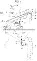
- Fig. 1 is a view illustrating a crane information display system of Example 1.
- a configuration of the crane information display system of Example 1 will be described.
- a crane information display system 100 of Example 1 will be described with an example in which a worker M captures an image of a crane 1 placed at a work site with a tablet terminal 50 as a user terminal provided with a camera 51, as illustrated in Fig. 1 .
- the crane information display system 100 of Example 1 will be described with an example in which an image of the crane 1 in a state in which an outrigger 80 does not extend is captured by the camera 51.
- the front-rear direction of the crane 1 is defined as a front-rear direction D.
- the crane 1 includes a traveling body 10, a turning body 20, and a boom 30.
- the traveling body 10 includes a vehicle body frame 11, the outrigger 80, a traveling device configured for self-traveling on a road or a work site, and the like.
- the outrigger 80 includes a rear outrigger 81 attached to a rear side surface of the vehicle body frame 11 of the traveling body 10 and a front outrigger 82 attached to a front side surface of the vehicle body frame 11.
- the outrigger 80 is housed in the vehicle body frame 11 during traveling.
- the outrigger 80 extends in the horizontal direction and the vertical direction and lifts the entire vehicle body to stabilize a posture.
- the turning body 20 is provided above the traveling body 10 and is rotatable about a vertical axis C1 relative to the traveling body 10.
- the turning body 20 includes a cabin 21.
- the cabin 21 includes operation units (e.g., a steering wheel, a shift lever, an accelerator pedal, a brake pedal, and the like) configured to control traveling of the traveling body 10. Further, the cabin 21 includes operation units that operate the turning body 20, the boom 30, a winch, and the like. A worker riding in the cabin 21 operates the operation units to turn the turning body 20, raise/lower and extend/contract the boom 30, and rotate the winch to perform the work.
- a crane reception unit 25 is attached to the turning body 20.
- the crane reception unit 25 (corresponding to a "second satellite positioning signal reception unit” of the present invention) receives a global navigation satellite system (GNSS) signal from a GNSS satellite serving as a satellite 90, for example, to execute positioning, and acquires position information of a turning center of the crane 1 in the real space.
- GNSS global navigation satellite system
- a base end side of the boom 30 is supported by the turning body 20, and is attached to the turning body 20 so as to be raised and lowered.
- the boom 30 is raised and lowered by a derricking cylinder 22 provided in the turning body 20, and is expanded and contracted by a telescopic cylinder (not illustrated).
- the boom 30 includes intermediate booms 32 to 35 between a base end boom 31 on the base end side and a distal end boom 36 on a distal end side.
- the intermediate booms 32 to 35 and the distal end boom 36 are telescopically stored in the base end boom 31 in sequence.
- a sheave 37 is arranged in a boom head 36a provided at a distal end of the distal end boom 36.
- a wire rope 38 for a suspended load is wound around the winch provided near the base end of the boom 30 of the turning body 20.
- the wire rope 38 is arranged along the axial direction of the boom 30 from the winch to the sheave 37, and the wire rope 38 wound around the sheave 37 is suspended downward in the vertical direction from the sheave 37.
- a hook 39 is provided at the lowermost portion of the wire rope 38.
- a load is suspended on the hook 39, and the wire rope 38 wound around the winch is unwound to lower the hook 39, and the wire rope 38 is wound up to raise the hook 39.
- the crane 1 configured in this manner moves the load suspended on the hook 39 to a predetermined position by unwinding and winding the wire rope 38 by the winch, raising/lowering and extending/contracting the boom 30, and turning the turning body 20.
- the tablet terminal 50 includes the camera 51, an image display unit 53, an input unit 52, and a camera reception unit 55.
- the image display unit 53 is also configured as a touch panel serving as the input unit 52.
- the camera reception unit 55 (corresponding to a "first satellite positioning signal reception unit” of the present invention) receives a global navigation satellite system (GNSS) signal from the GNSS satellite serving as the satellite 90, for example, to execute positioning, and acquires a position of the camera 51 in the real space, that is, position information of the tablet terminal 50.
- GNSS global navigation satellite system
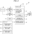
- Fig. 2 is a block diagram illustrating a functional configuration of the crane information display system 100 of Example 1.
- Fig. 3 is a table showing performance information of the crane stored in a storage unit 61 of Example 1.
- Fig. 4 is a view illustrating an image displayed on the image display unit 53 of Example 1.
- a functional configuration of the crane information display system 100 of Example 1 will be described.
- the position information of the camera 51 received from the satellite 90 by the camera reception unit 55, the position information of the turning center of the crane 1 received from the satellite 90 by the crane reception unit 25, and input information inputted by the input unit 52 are inputted to a control unit 60 (control unit built in the tablet terminal 50 in the present embodiment), and information controlled by the control unit 60 is outputted by the image display unit 53.
- the camera 51 can be configured as, for example, the camera 51 provided in the general tablet terminal 50.
- the camera 51 can capture an image of the crane 1 and a surrounding site environment of the crane 1.
- the input unit 52 includes a working radius input unit 52a, a hoisting load input unit 52b, and an extension amount input unit 52c.
- a working radius of the crane 1 can be inputted to the working radius input unit 52a.
- the working radius is a horizontal distance from a vertical line drawn from the center of the hook 39 to the vertical axis C1 which is the turning center of the turning body 20.
- the working radius is inputted by tapping a touch panel serving as the input unit 52.
- a hoisting load to be worked can be inputted to the hoisting load input unit 52b.
- the hoisting load is the weight (mass) of the suspended load and is the load applied to the crane 1.
- An extension amount of the outrigger 80 can be inputted to the extension amount input unit 52c.
- the extension amount of the outrigger 80 is an extension amount in the width direction of the crane 1.
- the length of the boom 30 is a length of the boom 30 in a state in which the distal end boom 36 and the intermediate booms 32 to 35 are stored in the base end boom 31 (fully contracted state), a length of the boom 30 in a state in which the distal end boom 36 is extended, a length in a state in which the distal end boom 36 and the intermediate booms 32 to 35 are extended (fully extended state), or the like.
- the control unit 60 includes the storage unit 61, a crane detection unit 62, an information processing unit 63, and a working capacity calculation unit 64.
- the control unit 60 is a known microcomputer including, for example, a central processing unit (CPU), a random access memory (RAM), a read only memory (ROM), and the like.
- the functions (the crane detection unit 62, the information processing unit 63, and the working capacity calculation unit 64) of the control unit 60 are achieved, for example, by the CPU referring to a control program and various types of data stored in the storage unit 61 (e.g., an HDD), the ROM, or the RAM.
- the storage unit 61 stores performance information of the crane 1.
- the performance information includes a rated total load table G associated with the extension amount of the outrigger 80.
- Fig. 3 illustrates, as an example, a rated total load according to the length of the boom 30 and the working radius in a case where the extension amount of the outrigger 80 is 6.6 [m].
- the rated total load is a limit value of the load that can be lifted with a predetermined length of the boom 30 and a predetermined working radius.
- the rated total load, the length of the boom 30, and the working radius are mutually related, and a limit value of the length of the boom 30, a limit value of a derricking angle of the boom 30, a limit value of a lifting height of the crane 1, and the like are specified when the rated total load and the working radius are determined, for example.
- the rated total load becomes 19.6 [t].
- the working radius is 10.0 [m]
- the length of the boom 30 is 30.5 [m]
- the rated total load becomes 7.15 [t].
- the crane detection unit 62 detects the crane 1 in the image captured by the camera 51 by image authentication on the basis of the image captured by the camera 51 of the crane 1 placed at the work site. Further, the crane detection unit 62 detects the turning center of the crane 1 in the image captured by the camera 51. As a result, an orientation of the crane 1 in the image from the camera 51 (that is, an orientation of the camera 51 with respect to the crane 1) is detected.
- the information processing unit 63 performs processing of associating the turning center of the crane 1 detected by the crane detection unit 62 with the position information of the camera 51 received by the camera reception unit 55 and the position information of the turning center of the crane 1 received by the crane reception unit 25.
- the information processing unit 63 acquires the orientation of the crane 1 in the image from the camera 51 (that is, the orientation of the camera 51 with respect to the crane 1) on the basis of the turning center of the crane 1 detected by the crane detection unit 62. Further, the information processing unit 63 associates the position of the camera 51 and the position of the turning center of the crane 1 with the image captured by the camera 51 on the basis of the orientation of the camera 51, the position information of the camera 51 received by the camera reception unit 55, and the position information of the turning center of the crane 1 received by the crane reception unit 25.
- the information processing unit 63 identifies the position and posture of the crane 1 in the coordinate system of the image from the camera 51 on the basis of the orientation of the camera 51 with respect to the crane 1, the position information of the camera 51 in the real space received by the camera reception unit 55, and the position information of the turning center of the crane 1 in the real space received by the crane reception unit 25.
- the working capacity calculation unit 64 calculates the working capacity of the crane 1 on the basis of the information relating to the crane 1 inputted to the input unit 52.
- the working capacity calculation unit 64 refers to the rated total load table G stored in the storage unit 61 on the basis of the working radius inputted to the working radius input unit 52a and the extension amount of the outrigger 80 inputted to the extension amount input unit 52c and calculates a maximum rated total load of the crane 1, a length of the boom 30 (that is, a limit value of the length of the boom 30), a derricking angle of the boom 30 (that is, a limit value of the derricking angle of the boom 30), and a lifting height of the crane 1 (that is, a limit value of the lifting height of the crane 1).
- the length of the boom 30, the derricking angle of the boom 30, and the lifting height of the crane 1 calculated by the working capacity calculation unit 64 are a limit value within a range that the length of the boom 30 can take, a limit value within a range that the derricking angle of the boom 30 can take, and a limit value within a range that the lifting height of the crane 1 can take under conditions of the working radius inputted to the working radius input unit 52a, the extension amount of the outrigger 80 inputted to the extension amount input unit 52c, and the maximum rated total load of the crane 1 identified from the rated total load table G.
- the working capacity calculation unit 64 refers to the rated total load table G and calculates the maximum rated total load of the crane 1 as 19.6 [t]. Further, the working capacity calculation unit 64 calculates the length of the boom 30 at that time as 9.35 [m]. Further, the working capacity calculation unit 64 calculates the derricking angle of the boom 30 and the lifting height of the crane 1 on the basis of the working radius inputted to the working radius input unit 52a and the calculated length of the boom 30.
- the working capacity calculation unit 64 selects 19.6 [t] as the maximum rated total load under conditions that the working radius is 5 [m] and the extension amount of the outrigger 80 is 6.6 [m] from among rated total loads of the crane 1 defined in the rated total load table G of Fig. 3 , and calculates the length and the like of the boom 30 so as to correspond to the rated total load.
- the working capacity calculation unit 64 may determine the rated total load of the crane 1 on the basis of the working radius inputted to the input unit 52, the extension amount of the outrigger 80, and the length of the boom 30.
- the image display unit 53 superimposes, on the image of the crane 1 and the surrounding site environment thereof captured by the camera 51, a working radius E1 inputted to the working radius input unit 52a, an extension amount E2 of the outrigger 80 inputted to the extension amount input unit 52c, a maximum rated total load F1 of the crane 1, a length F2 of the boom 30 (that is, the limit value of the length of the boom 30), a derricking angle F3 of the boom 30 (that is, the limit value of the derricking angle of the boom 30), and a lifting height F4 of the crane 1 (that is, the limit value of the lifting height of the crane 1), on the basis of the information processed by the information processing unit 63, and displays the superimposed image.
- the image display unit 53 displays at least a part of the information of the maximum rated total load F1 of the crane 1, the length F2 of the boom 30, the derricking angle F3 of the boom 30, and the lifting height F4 of the crane 1 as a three-dimensional image to be overlaid on the crane 1 or the surrounding environment of the crane 1 in the image from the camera 51 such that a user can three-dimensionally examine how the site environment is affected by each part of the crane 1 at the time of actually operating the crane 1 at the site.
- pieces of the information on the length F2 of the boom 30 and the derricking angle F3 of the boom 30 are displayed as a three-dimensional image by a dotted line so as to be overlaid on the crane 1 in the image from the camera 51.
- Fig. 5 is a flowchart illustrating a flow of processing performed by the control unit 60 of the crane information display system 100 of Example 1.
- the flow of processing performed by the control unit 60 of the crane information display system 100 of Example 1 will be described.
- the control unit 60 acquires information on a position of a turning center of the crane 1 inputted from the crane reception unit 25 and information on a position of the camera 51 inputted from the camera reception unit 55, as illustrated in Fig. 5 (step S101).
- the crane detection unit 62 detects the turning center of the crane 1 on the basis of the image obtained by capturing the crane 1 placed at the work site with the camera 51 (step S102).
- the information processing unit 63 acquires the orientation of the camera 51 on the basis of the turning center of the crane 1 detected by the crane detection unit 62 (step S103).
- the information processing unit 63 performs processing of associating the position of the camera 51 and the position of the turning center of the crane 1 with the image captured by the camera 51 on the basis of the orientation of the camera 51, the position information of the camera 51 received by the camera reception unit 55, and the position information of the turning center of the crane 1 received by the crane reception unit 25 (step S104).
- control unit 60 acquires the working radius E1 inputted to the working radius input unit 52a and the extension amount E2 of the outrigger 80 inputted to the extension amount input unit 52c (step S105).
- the working capacity calculation unit 64 calculates the maximum rated total load F1 of the crane 1, the length F2 of the boom 30, the derricking angle F3 of the boom 30, and the lifting height F4 of the crane 1 on the basis of the working radius E1 inputted to the working radius input unit 52a and the extension amount E2 of the outrigger 80 inputted to the extension amount input unit 52c (step S106).
- the image display unit 53 superimposes, on the image of the crane 1 and the surrounding site environment thereof captured by the camera 51, the working radius E1 inputted to the working radius input unit 52a, the extension amount E2 of the outrigger 80 inputted to the extension amount input unit 52c, the maximum rated total load F1 of the crane 1, the length F2 of the boom 30, the derricking angle F3 of the boom 30, and the lifting height F4 of the crane 1, displays the superimposed image (step S107), and ends the processing.
- a vector from the time of initialization may be acquired by a SLAM technique or an acceleration sensor to follow the vector.
- the crane information display system 100 of Example 1 includes: the crane detection unit 62 that detects the crane 1 placed at a work site on the basis of an image of the crane 1 captured by the camera 51; the camera reception unit 55 that is mounted on the camera 51 and receives position information of the camera 51 from the satellite 90; the crane reception unit 25 that is mounted on the crane 1 and receives position information of the crane 1 from the satellite 90; the information processing unit 63 that performs processing of associating the crane 1 detected by the crane detection unit 62 with the position information of the camera 51 received by the camera reception unit 55 and the position information of the crane 1 received by the crane reception unit 25; the input unit 52 that inputs information relating to the crane 1; the working capacity calculation unit 64 that calculates the working capacity of the crane 1 based on the information relating to the crane 1 inputted to the input unit 52; and the image display unit 53 that displays the working capacity of the crane 1 calculated by the working capacity calculation unit 64 on the image captured by the camera 51 based on the information processed by the information processing unit 63 ( Figs. 2 and
- the working capacity of the crane 1 can be overlaid on the image of the actual crane 1 arranged at the work site. Therefore, the crane 1, the surrounding environment thereof, and the working capacity of the crane 1 can be confirmed by the three-dimensional image in real time. As a result, a work plan of the crane 1 can be examined in real time at the work site.
- the input unit 52 includes the working radius input unit 52a to which the working radius E1 of the crane 1 is inputted, and the working capacity calculation unit 64 calculates the maximum rated total load F1 of the crane 1 on the basis of an input value of the working radius input unit 52a ( Figs. 2 and 4 ).
- the working capacity calculation unit 64 calculates the length F2 of the boom 30 and the derricking angle F3 of the boom 30 on the basis of an input value of the input unit 52 ( Figs. 2 and 4 ).
- the input unit 52 includes the extension amount input unit 52c that inputs the extension amount E2 of the outrigger, and the working capacity calculation unit 64 calculates the working capacity of the crane 1 on the basis of an input value of the extension amount input unit 52c ( Figs. 2 and 4 ).
- a crane information display system of Example 2 is different from the crane information display system of Example 1 in that a working capacity calculation unit has a different configuration.
- Fig. 6 is a view illustrating an image displayed on an image display unit of Example 2.
- a configuration of the crane information display system of Example 2 will be described. Note that the same or equivalent portions as the content described in Example 1 will be described using the same terms or the same reference signs.
- the working capacity calculation unit 64 calculates the working capacity of the crane 1 on the basis of the information relating to the crane 1 inputted to the input unit 52.
- the working capacity calculation unit 64 refers to the rated total load table G stored in the storage unit 61 on the basis of a hoisting load inputted to the hoisting load input unit 52b and an extension amount of the outrigger 80 inputted to the extension amount input unit 52c and calculates a maximum working radius of the crane 1, a length of the boom 30 (that is, a limit value of the length of the boom 30), a derricking angle of the boom 30 (that is, a limit value of the derricking angle of the boom 30), and a lifting height of the crane 1 (that is, a limit value of the lifting height of the boom 30).
- the working capacity calculation unit 64 refers to the rated total load table G and calculates the maximum working radius of the crane 1 as 6.5 [m]. Further, the working capacity calculation unit 64 calculates the length of the boom 30 at that time as 16.4 [m]. Further, the working capacity calculation unit 64 calculates the derricking angle of the boom 30 and the lifting height of the crane 1 on the basis of the calculated maximum working radius and the calculated length of the boom 30.
- the image display unit 53 superimposes, on an image of the crane 1 and a surrounding site environment thereof captured by the camera 51, a hoisting load G1 of a suspended load 5 to be worked, which has been inputted to the hoisting load input unit 52b, an extension amount G2 of the outrigger 80 inputted to the extension amount input unit 52c, a maximum working radius H1 of the crane 1, a length H2 of the boom 30, a derricking angle H3 of the boom 30, and a lifting height H4 of the crane 1, on the basis of the information processed by the information processing unit 63, and displays the superimposed image.
- Fig. 7 is a flowchart illustrating a flow of processing performed by the control unit 60 of the crane information display system 100 of Example 2.
- the flow of processing performed by the control unit 60 of the crane information display system 100 of Example 2 will be described.
- the control unit 60 acquires information on a position of a turning center of the crane 1 inputted from the crane reception unit 25 and information on a position of the camera 51 inputted from the camera reception unit 55, as illustrated in Fig. 7 (step S201).
- the crane detection unit 62 detects the turning center of the crane 1 on the basis of the image obtained by capturing the crane 1 placed at the work site with the camera 51 (step S202).
- the information processing unit 63 acquires the orientation of the camera 51 on the basis of the turning center of the crane 1 detected by the crane detection unit 62 (step S203).
- the information processing unit 63 performs processing of associating the position of the camera 51 and the position of the turning center of the crane 1 with the image captured by the camera 51 on the basis of the orientation of the camera 51, the position information of the camera 51 received by the camera reception unit 55, and the position information of the turning center of the crane 1 received by the crane reception unit 25 (step S204).
- control unit 60 acquires the hoisting load G1 inputted to the hoisting load input unit 52b and the extension amount G2 of the outrigger 80 inputted to the extension amount input unit 52c (step S105).
- the working capacity calculation unit 64 calculates the maximum working radius H1 of the crane 1, the length H2 of the boom 30, the derricking angle H3 of the boom 30, and the lifting height H4 of the crane 1 on the basis of the hoisting load G1 inputted to the hoisting load input unit 52b and the extension amount G2 of the outrigger 80 inputted to the extension amount input unit 52c (step S206).
- the image display unit 53 superimposes, on the image of the crane 1 and the surrounding site environment thereof captured by the camera 51, the hoisting load G1 inputted to the hoisting load input unit 52b, the extension amount G2 of the outrigger 80 inputted to the extension amount input unit 52c, the maximum working radius H1 of the crane 1, the length H2 of the boom 30, the derricking angle H3 of the boom 30, and the lifting height H4 of the crane 1, displays the superimposed image (step S207), and ends the processing.
- a vector from the time of initialization may be acquired by a SLAM technique or an acceleration sensor to follow the vector.
- the input unit 52 includes the hoisting load input unit 52b that inputs the hoisting load G1, and the working capacity calculation unit 64 calculates the maximum working radius H1 of the crane 1 on the basis of an input value of the hoisting load input unit 52b ( Figs. 2 and 6 ).
- the maximum working radius H1 can be calculated for a suspended load to be worked. Therefore, it is possible to easily examine a start position and an end position between which the crane 1 is moved with respect to the suspended load to be worked. Further, it is also possible to examine an installation position where the crane 1 is installed next. Further, when the maximum working radii H1 of a plurality of cranes are confirmed by the image display unit 53, the interference between the cranes can be avoided.
- a crane information display system of Example 3 is different from the crane information display system of Example 1 in that a working capacity calculation unit has a different configuration.
- Fig. 8 is a view illustrating an image displayed on an image display unit of Example 3.
- a configuration of the crane information display system of Example 3 will be described. Note that the same or equivalent portions as the content described in Example 1 will be described using the same terms or the same reference signs.
- the working capacity calculation unit 64 calculates the working capacity of the crane 1 on the basis of the information relating to the crane 1 inputted to the input unit 52.
- the working capacity calculation unit 64 refers to the rated total load table G stored in the storage unit 61 on the basis of a working radius inputted to the working radius input unit 52a, a hoisting load inputted to the hoisting load input unit 52b, and an extension amount of the outrigger 80 inputted to the extension amount input unit 52c and calculates a lowest lifting height of the crane 1, a length of the boom 30 (that is, a limit value of the length of the boom 30), and a derricking angle of the boom 30 (that is, a limit value of the derricking angle of the boom 30).
- the working capacity calculation unit 64 refers to the rated total load table G and calculates the lowest lifting height of the crane 1 and the length of the boom 30. Further, the working capacity calculation unit 64 calculates the derricking angle of the boom 30 on the basis of the input working radius and the calculated length of the boom 30.
- the image display unit 53 superimposes, on an image of the crane 1 and a surrounding site environment thereof captured by the camera 51, a working radius M1 inputted to the working radius input unit 52a, a hoisting load M2 inputted to the hoisting load input unit 52b, an extension amount M3 of the outrigger 80 inputted to the extension amount input unit 52c, a lowest lifting height N1 of the crane 1, a length N2 of the boom 30, and a derricking angle N3 of the boom 30, on the basis of the information processed by the information processing unit 63, and displays the superimposed image.
- Fig. 9 is a flowchart illustrating a flow of processing performed by the control unit 60 of the crane information display system 100 of Example 3.
- the flow of processing performed by the control unit 60 of the crane information display system 100 of Example 3 will be described.
- the control unit 60 acquires information on a position of a turning center of the crane 1 inputted from the crane reception unit 25 and information on a position of the camera 51 inputted from the camera reception unit 55, as illustrated in Fig. 9 (step S301).
- the crane detection unit 62 detects the turning center of the crane 1 on the basis of the image obtained by capturing the crane 1 placed at the work site with the camera 51 (step S302).
- the information processing unit 63 acquires the orientation of the camera 51 on the basis of the turning center of the crane 1 detected by the crane detection unit 62 (step S303).
- the information processing unit 63 performs processing of associating the position of the camera 51 and the position of the turning center of the crane 1 with the image captured by the camera 51 on the basis of the orientation of the camera 51, the position information of the camera 51 received by the camera reception unit 55, and the position information of the turning center of the crane 1 received by the crane reception unit 25 (step S304).
- control unit 60 acquires the working radius M1 inputted to the working radius input unit 52a, the hoisting load M2 inputted to the hoisting load input unit 52b, and the extension amount M3 of the outrigger 80 inputted to the extension amount input unit 52c (step S305).
- the working capacity calculation unit 64 calculates the extension amount M3 of the outrigger 80 inputted to the extension amount input unit 52c, the lowest lifting height N1 of the crane 1, the length N2 of the boom 30, and the derricking angle N3 of the boom 30 on the basis of the working radius M1 inputted to the working radius input unit 52a, the hoisting load M2 inputted to the hoisting load input unit 52b, and the extension amount M3 of the outrigger 80 inputted to the extension amount input unit 52c (step S306).
- the image display unit 53 superimposes, on the image of the crane 1 and the surrounding site environment thereof captured by the camera 51, the working radius M1 inputted to the working radius input unit 52a, the hoisting load M2 inputted to the hoisting load input unit 52b, the extension amount M3 of the outrigger 80 inputted to the extension amount input unit 52c, the lowest lifting height N1 of the crane 1, the length N2 of the boom 30, and the derricking angle N3 of the boom 30, displays the superimposed image (step S307), and ends the processing.
- a vector from the time of initialization may be acquired by a SLAM technique or an acceleration sensor to follow the vector.
- the input unit 52 includes the working radius input unit 52a to which the working radius M1 of the crane 1 is inputted and the hoisting load input unit 52b to which the hoisting load M2 is inputted, and the working capacity calculation unit 64 calculates the lowest lifting height N1 of the crane 1 on the basis of an input value of the working radius input unit 52a and an input value of the hoisting load input unit 52b.
- the lowest lifting height N1 can be calculated for a hoisting load to be worked at a desired position. Therefore, it is possible to examine the lowest lifting height to move a suspended load to be worked from a start position to an end position by the crane 1. As a result, it is possible to perform an examination for reducing a work area of the crane 1.
- Examples 1 to 3 have illustrated the example in which the touch panel serving as the input unit 52 is tapped to input the working radius to the working radius input unit 52a.
- a reception unit that receives a global navigation satellite system (GNSS) signal from a GNSS satellite serving as the satellite 90 may be installed at a target point of the work site, and the signal from the reception unit may be inputted to the input unit.
- GNSS global navigation satellite system
- Examples 1 to 3 have illustrated the example in which the working radius does not take into consideration a bending amount of the boom 30. However, the working radius can also take into account the amount of bending of the boom.
- Examples 1 to 3 have illustrated the example in which the user terminal is the tablet terminal 50 including the camera 51, the input unit 52, and the image display unit 53.
- the user terminal may be a smart phone.
- the user terminal may include a camera and an image display unit which are separate bodies.
- Examples 1 to 3 have illustrated the example in which the present invention is applied to the crane 1 including the boom 30. However, the present invention can be applied to a crane including a jib.
Landscapes
- Engineering & Computer Science (AREA)
- Mechanical Engineering (AREA)
- Automation & Control Theory (AREA)
- Computer Vision & Pattern Recognition (AREA)
- Physics & Mathematics (AREA)
- General Physics & Mathematics (AREA)
- Theoretical Computer Science (AREA)
- Multimedia (AREA)
- Signal Processing (AREA)
- Jib Cranes (AREA)
- Control And Safety Of Cranes (AREA)
Abstract
Description
- The present invention relates to a crane information display system.
- Conventionally, a crane information display system that displays information of a crane is known (e.g., refer to Patent Literature 1).
-
Patent Literature 1 discloses a configuration that visualizes information relating to an operating state of a crane and displays a display screen on a display unit of a mobile terminal. As a result, even a person outside the crane can grasp the operating state of the crane. - Patent Literature 1:
JP 2014-227281 A - In the configuration described in
Patent Literature 1, however, the information relating to the operating state of the crane is visualized and displayed by drawing the crane from above or from the side. Therefore, the configuration described inPatent Literature 1 has a problem that a two-dimensional examination is required. - Therefore, an object of the present invention is to provide a crane information display system capable of three-dimensionally examining information relating to a crane at a work site.
- A main aspect of the present disclosure for solving the above-described problems is a crane information display system that is provided with a terminal device having a camera and captures an image of a crane with the camera to obtain a camera image. The crane information display system includes: a crane detection unit that detects the crane in the camera image based on image information of the camera image; an information processing unit that identifies a position and a posture of the crane in a coordinate system of the camera image based on an orientation of the camera with respect to the crane identified from the crane in the camera image, a position of the camera in a real space indicated by a first satellite positioning signal reception unit mounted on the camera, and a position of the crane in a real space indicated by a second satellite positioning signal reception unit mounted on the crane; a working capacity calculation unit that calculates a working capacity of the crane based on information relating to the crane inputted to an input unit; and an image display unit that converts the working capacity of the crane into three-dimensional image information corresponding to the position and the posture of the crane identified by the information processing unit, overlays the image information on the camera image, and displays the overlaid image.
- In the crane information display system of the present invention configured as described above, the information relating to the crane can be examined three-dimensionally at the work site.
- Brief Description of Drawings
-
-
Fig. 1 is a view illustrating a crane information display system of Example 1. -
Fig. 2 is a block diagram illustrating a functional configuration of the crane information display system of Example 1. -
Fig. 3 is a table showing performance information of a crane stored in a storage unit of Example 1. -
Fig. 4 is a view illustrating an image displayed on an image display unit of Example 1. -
Fig. 5 is a flowchart illustrating a flow of processing performed by a control unit of the crane information display system of Example 1. -
Fig. 6 is a view illustrating an image displayed on an image display unit of Example 2. -
Fig. 7 is a flowchart illustrating a flow of processing performed by a control unit of a crane information display system of Example 2. -
Fig. 8 is a view illustrating an image displayed on an image display unit of Example 3. -
Fig. 9 is a flowchart illustrating a flow of processing performed by a control unit of a crane information display system of Example 3. - Hereinafter, embodiments for implementing a crane information display system according to the present invention will be described with reference to Examples 1 to 3 illustrated in the drawings.
-
Fig. 1 is a view illustrating a crane information display system of Example 1. Hereinafter, a configuration of the crane information display system of Example 1 will be described. - A crane
information display system 100 of Example 1 will be described with an example in which a worker M captures an image of acrane 1 placed at a work site with atablet terminal 50 as a user terminal provided with acamera 51, as illustrated inFig. 1 . The craneinformation display system 100 of Example 1 will be described with an example in which an image of thecrane 1 in a state in which anoutrigger 80 does not extend is captured by thecamera 51. Note that the front-rear direction of thecrane 1 is defined as a front-rear direction D. - As illustrated in
Fig. 1 , thecrane 1 includes atraveling body 10, a turningbody 20, and aboom 30. - The
traveling body 10 includes avehicle body frame 11, theoutrigger 80, a traveling device configured for self-traveling on a road or a work site, and the like. - The
outrigger 80 includes arear outrigger 81 attached to a rear side surface of thevehicle body frame 11 of thetraveling body 10 and afront outrigger 82 attached to a front side surface of thevehicle body frame 11. Theoutrigger 80 is housed in thevehicle body frame 11 during traveling. On the other hand, theoutrigger 80 extends in the horizontal direction and the vertical direction and lifts the entire vehicle body to stabilize a posture. - The turning
body 20 is provided above thetraveling body 10 and is rotatable about a vertical axis C1 relative to thetraveling body 10. The turningbody 20 includes acabin 21. Thecabin 21 includes operation units (e.g., a steering wheel, a shift lever, an accelerator pedal, a brake pedal, and the like) configured to control traveling of thetraveling body 10. Further, thecabin 21 includes operation units that operate the turningbody 20, theboom 30, a winch, and the like. A worker riding in thecabin 21 operates the operation units to turn the turningbody 20, raise/lower and extend/contract theboom 30, and rotate the winch to perform the work. - A
crane reception unit 25 is attached to the turningbody 20. The crane reception unit 25 (corresponding to a "second satellite positioning signal reception unit" of the present invention) receives a global navigation satellite system (GNSS) signal from a GNSS satellite serving as asatellite 90, for example, to execute positioning, and acquires position information of a turning center of thecrane 1 in the real space. - A base end side of the
boom 30 is supported by the turningbody 20, and is attached to the turningbody 20 so as to be raised and lowered. Theboom 30 is raised and lowered by a derrickingcylinder 22 provided in the turningbody 20, and is expanded and contracted by a telescopic cylinder (not illustrated). - The
boom 30 includes intermediate booms 32 to 35 between abase end boom 31 on the base end side and adistal end boom 36 on a distal end side. The intermediate booms 32 to 35 and thedistal end boom 36 are telescopically stored in thebase end boom 31 in sequence. - A
sheave 37 is arranged in aboom head 36a provided at a distal end of thedistal end boom 36. Awire rope 38 for a suspended load is wound around the winch provided near the base end of theboom 30 of the turningbody 20. Thewire rope 38 is arranged along the axial direction of theboom 30 from the winch to thesheave 37, and thewire rope 38 wound around thesheave 37 is suspended downward in the vertical direction from thesheave 37. Ahook 39 is provided at the lowermost portion of thewire rope 38. - A load is suspended on the
hook 39, and thewire rope 38 wound around the winch is unwound to lower thehook 39, and thewire rope 38 is wound up to raise thehook 39. - The
crane 1 configured in this manner moves the load suspended on thehook 39 to a predetermined position by unwinding and winding thewire rope 38 by the winch, raising/lowering and extending/contracting theboom 30, and turning the turningbody 20. - As illustrated in
Fig. 1 , thetablet terminal 50 includes thecamera 51, animage display unit 53, aninput unit 52, and acamera reception unit 55. - An image captured by the
camera 51 is displayed on theimage display unit 53. Theimage display unit 53 is also configured as a touch panel serving as theinput unit 52. - The camera reception unit 55 (corresponding to a "first satellite positioning signal reception unit" of the present invention) receives a global navigation satellite system (GNSS) signal from the GNSS satellite serving as the
satellite 90, for example, to execute positioning, and acquires a position of thecamera 51 in the real space, that is, position information of thetablet terminal 50. -
Fig. 2 is a block diagram illustrating a functional configuration of the craneinformation display system 100 of Example 1.Fig. 3 is a table showing performance information of the crane stored in astorage unit 61 of Example 1.Fig. 4 is a view illustrating an image displayed on theimage display unit 53 of Example 1. Hereinafter, a functional configuration of the craneinformation display system 100 of Example 1 will be described. - In the crane
information display system 100, the position information of thecamera 51 received from thesatellite 90 by thecamera reception unit 55, the position information of the turning center of thecrane 1 received from thesatellite 90 by thecrane reception unit 25, and input information inputted by theinput unit 52 are inputted to a control unit 60 (control unit built in thetablet terminal 50 in the present embodiment), and information controlled by thecontrol unit 60 is outputted by theimage display unit 53. - The
camera 51 can be configured as, for example, thecamera 51 provided in thegeneral tablet terminal 50. Thecamera 51 can capture an image of thecrane 1 and a surrounding site environment of thecrane 1. - Information relating to the
crane 1 can be inputted to theinput unit 52. Theinput unit 52 includes a workingradius input unit 52a, a hoistingload input unit 52b, and an extensionamount input unit 52c. - A working radius of the
crane 1 can be inputted to the workingradius input unit 52a. The working radius is a horizontal distance from a vertical line drawn from the center of thehook 39 to the vertical axis C1 which is the turning center of the turningbody 20. The working radius is inputted by tapping a touch panel serving as theinput unit 52. - A hoisting load to be worked can be inputted to the hoisting
load input unit 52b. The hoisting load is the weight (mass) of the suspended load and is the load applied to thecrane 1. - An extension amount of the
outrigger 80 can be inputted to the extensionamount input unit 52c. The extension amount of theoutrigger 80 is an extension amount in the width direction of thecrane 1. - Further, a length of the
boom 30 and the like can be inputted to theinput unit 52. The length of theboom 30 is a length of theboom 30 in a state in which thedistal end boom 36 and the intermediate booms 32 to 35 are stored in the base end boom 31 (fully contracted state), a length of theboom 30 in a state in which thedistal end boom 36 is extended, a length in a state in which thedistal end boom 36 and the intermediate booms 32 to 35 are extended (fully extended state), or the like. - The
control unit 60 includes thestorage unit 61, acrane detection unit 62, aninformation processing unit 63, and a workingcapacity calculation unit 64. Note that thecontrol unit 60 is a known microcomputer including, for example, a central processing unit (CPU), a random access memory (RAM), a read only memory (ROM), and the like. The functions (thecrane detection unit 62, theinformation processing unit 63, and the working capacity calculation unit 64) of thecontrol unit 60 are achieved, for example, by the CPU referring to a control program and various types of data stored in the storage unit 61 (e.g., an HDD), the ROM, or the RAM. - The
storage unit 61 stores performance information of thecrane 1. The performance information includes a rated total load table G associated with the extension amount of theoutrigger 80.Fig. 3 illustrates, as an example, a rated total load according to the length of theboom 30 and the working radius in a case where the extension amount of theoutrigger 80 is 6.6 [m]. The rated total load is a limit value of the load that can be lifted with a predetermined length of theboom 30 and a predetermined working radius. In other words, the rated total load, the length of theboom 30, and the working radius are mutually related, and a limit value of the length of theboom 30, a limit value of a derricking angle of theboom 30, a limit value of a lifting height of thecrane 1, and the like are specified when the rated total load and the working radius are determined, for example. - For example, in a case where the extension amount of the
outrigger 80 is 6.6 [m], the working radius is 5.0 [m] and the length of theboom 30 is 9.35 [m], the rated total load becomes 19.6 [t]. In a case where the extension amount of theoutrigger 80 is 6.6 [m], the working radius is 10.0 [m], and the length of theboom 30 is 30.5 [m], the rated total load becomes 7.15 [t]. - The
crane detection unit 62 detects thecrane 1 in the image captured by thecamera 51 by image authentication on the basis of the image captured by thecamera 51 of thecrane 1 placed at the work site. Further, thecrane detection unit 62 detects the turning center of thecrane 1 in the image captured by thecamera 51. As a result, an orientation of thecrane 1 in the image from the camera 51 (that is, an orientation of thecamera 51 with respect to the crane 1) is detected. - The
information processing unit 63 performs processing of associating the turning center of thecrane 1 detected by thecrane detection unit 62 with the position information of thecamera 51 received by thecamera reception unit 55 and the position information of the turning center of thecrane 1 received by thecrane reception unit 25. - Specifically, the
information processing unit 63 acquires the orientation of thecrane 1 in the image from the camera 51 (that is, the orientation of thecamera 51 with respect to the crane 1) on the basis of the turning center of thecrane 1 detected by thecrane detection unit 62. Further, theinformation processing unit 63 associates the position of thecamera 51 and the position of the turning center of thecrane 1 with the image captured by thecamera 51 on the basis of the orientation of thecamera 51, the position information of thecamera 51 received by thecamera reception unit 55, and the position information of the turning center of thecrane 1 received by thecrane reception unit 25. That is, theinformation processing unit 63 identifies the position and posture of thecrane 1 in the coordinate system of the image from thecamera 51 on the basis of the orientation of thecamera 51 with respect to thecrane 1, the position information of thecamera 51 in the real space received by thecamera reception unit 55, and the position information of the turning center of thecrane 1 in the real space received by thecrane reception unit 25. - The working
capacity calculation unit 64 calculates the working capacity of thecrane 1 on the basis of the information relating to thecrane 1 inputted to theinput unit 52. In Example 1, the workingcapacity calculation unit 64 refers to the rated total load table G stored in thestorage unit 61 on the basis of the working radius inputted to the workingradius input unit 52a and the extension amount of theoutrigger 80 inputted to the extensionamount input unit 52c and calculates a maximum rated total load of thecrane 1, a length of the boom 30 (that is, a limit value of the length of the boom 30), a derricking angle of the boom 30 (that is, a limit value of the derricking angle of the boom 30), and a lifting height of the crane 1 (that is, a limit value of the lifting height of the crane 1). - Here, the length of the
boom 30, the derricking angle of theboom 30, and the lifting height of thecrane 1 calculated by the workingcapacity calculation unit 64 are a limit value within a range that the length of theboom 30 can take, a limit value within a range that the derricking angle of theboom 30 can take, and a limit value within a range that the lifting height of thecrane 1 can take under conditions of the working radius inputted to the workingradius input unit 52a, the extension amount of theoutrigger 80 inputted to the extensionamount input unit 52c, and the maximum rated total load of thecrane 1 identified from the rated total load table G. - For example, in a case where the working radius inputted to the working
radius input unit 52a is 5 [m] and the extension amount of theoutrigger 80 inputted to the extensionamount input unit 52c is 6.6 [m] as illustrated inFig. 3 , the workingcapacity calculation unit 64 refers to the rated total load table G and calculates the maximum rated total load of thecrane 1 as 19.6 [t]. Further, the workingcapacity calculation unit 64 calculates the length of theboom 30 at that time as 9.35 [m]. Further, the workingcapacity calculation unit 64 calculates the derricking angle of theboom 30 and the lifting height of thecrane 1 on the basis of the working radius inputted to the workingradius input unit 52a and the calculated length of theboom 30. - Here, the working
capacity calculation unit 64 selects 19.6 [t] as the maximum rated total load under conditions that the working radius is 5 [m] and the extension amount of theoutrigger 80 is 6.6 [m] from among rated total loads of thecrane 1 defined in the rated total load table G ofFig. 3 , and calculates the length and the like of theboom 30 so as to correspond to the rated total load. However, when the length of theboom 30 can be inputted to theinput unit 52, the workingcapacity calculation unit 64 may determine the rated total load of thecrane 1 on the basis of the working radius inputted to theinput unit 52, the extension amount of theoutrigger 80, and the length of theboom 30. - As illustrated in
Fig. 4 , theimage display unit 53 superimposes, on the image of thecrane 1 and the surrounding site environment thereof captured by thecamera 51, a working radius E1 inputted to the workingradius input unit 52a, an extension amount E2 of theoutrigger 80 inputted to the extensionamount input unit 52c, a maximum rated total load F1 of thecrane 1, a length F2 of the boom 30 (that is, the limit value of the length of the boom 30), a derricking angle F3 of the boom 30 (that is, the limit value of the derricking angle of the boom 30), and a lifting height F4 of the crane 1 (that is, the limit value of the lifting height of the crane 1), on the basis of the information processed by theinformation processing unit 63, and displays the superimposed image. - At this time, the
image display unit 53 displays at least a part of the information of the maximum rated total load F1 of thecrane 1, the length F2 of theboom 30, the derricking angle F3 of theboom 30, and the lifting height F4 of thecrane 1 as a three-dimensional image to be overlaid on thecrane 1 or the surrounding environment of thecrane 1 in the image from thecamera 51 such that a user can three-dimensionally examine how the site environment is affected by each part of thecrane 1 at the time of actually operating thecrane 1 at the site. InFig. 4 , pieces of the information on the length F2 of theboom 30 and the derricking angle F3 of theboom 30 are displayed as a three-dimensional image by a dotted line so as to be overlaid on thecrane 1 in the image from thecamera 51. -
Fig. 5 is a flowchart illustrating a flow of processing performed by thecontrol unit 60 of the craneinformation display system 100 of Example 1. Hereinafter, the flow of processing performed by thecontrol unit 60 of the craneinformation display system 100 of Example 1 will be described. - When the worker M captures an image of the
crane 1 installed at a work site and a surrounding work environment thereof with thecamera 51 of thetablet terminal 50, thecontrol unit 60 acquires information on a position of a turning center of thecrane 1 inputted from thecrane reception unit 25 and information on a position of thecamera 51 inputted from thecamera reception unit 55, as illustrated inFig. 5 (step S101). - Next, the
crane detection unit 62 detects the turning center of thecrane 1 on the basis of the image obtained by capturing thecrane 1 placed at the work site with the camera 51 (step S102). - Next, the
information processing unit 63 acquires the orientation of thecamera 51 on the basis of the turning center of thecrane 1 detected by the crane detection unit 62 (step S103). - Next, the
information processing unit 63 performs processing of associating the position of thecamera 51 and the position of the turning center of thecrane 1 with the image captured by thecamera 51 on the basis of the orientation of thecamera 51, the position information of thecamera 51 received by thecamera reception unit 55, and the position information of the turning center of thecrane 1 received by the crane reception unit 25 (step S104). - Next, the
control unit 60 acquires the working radius E1 inputted to the workingradius input unit 52a and the extension amount E2 of theoutrigger 80 inputted to the extensionamount input unit 52c (step S105). - Next, the working
capacity calculation unit 64 calculates the maximum rated total load F1 of thecrane 1, the length F2 of theboom 30, the derricking angle F3 of theboom 30, and the lifting height F4 of thecrane 1 on the basis of the working radius E1 inputted to the workingradius input unit 52a and the extension amount E2 of theoutrigger 80 inputted to the extensionamount input unit 52c (step S106). - Next, the
image display unit 53 superimposes, on the image of thecrane 1 and the surrounding site environment thereof captured by thecamera 51, the working radius E1 inputted to the workingradius input unit 52a, the extension amount E2 of theoutrigger 80 inputted to the extensionamount input unit 52c, the maximum rated total load F1 of thecrane 1, the length F2 of theboom 30, the derricking angle F3 of theboom 30, and the lifting height F4 of thecrane 1, displays the superimposed image (step S107), and ends the processing. - Note that, in a case where the orientation of the
camera 51 is changed, a vector from the time of initialization may be acquired by a SLAM technique or an acceleration sensor to follow the vector. - Hereinafter, functions and effects of the crane
information display system 100 of Example 1 will be described. - The crane
information display system 100 of Example 1 includes: thecrane detection unit 62 that detects thecrane 1 placed at a work site on the basis of an image of thecrane 1 captured by thecamera 51; thecamera reception unit 55 that is mounted on thecamera 51 and receives position information of thecamera 51 from thesatellite 90; thecrane reception unit 25 that is mounted on thecrane 1 and receives position information of thecrane 1 from thesatellite 90; theinformation processing unit 63 that performs processing of associating thecrane 1 detected by thecrane detection unit 62 with the position information of thecamera 51 received by thecamera reception unit 55 and the position information of thecrane 1 received by thecrane reception unit 25; theinput unit 52 that inputs information relating to thecrane 1; the workingcapacity calculation unit 64 that calculates the working capacity of thecrane 1 based on the information relating to thecrane 1 inputted to theinput unit 52; and theimage display unit 53 that displays the working capacity of thecrane 1 calculated by the workingcapacity calculation unit 64 on the image captured by thecamera 51 based on the information processed by the information processing unit 63 (Figs. 2 and4 ). - As a result, the working capacity of the
crane 1 can be overlaid on the image of theactual crane 1 arranged at the work site. Therefore, thecrane 1, the surrounding environment thereof, and the working capacity of thecrane 1 can be confirmed by the three-dimensional image in real time. As a result, a work plan of thecrane 1 can be examined in real time at the work site. - In the crane
information display system 100 of Example 1, theinput unit 52 includes the workingradius input unit 52a to which the working radius E1 of thecrane 1 is inputted, and the workingcapacity calculation unit 64 calculates the maximum rated total load F1 of thecrane 1 on the basis of an input value of the workingradius input unit 52a (Figs. 2 and4 ). - As a result, it is possible to know a maximum rated total load at a desired point. Therefore, it is possible to know a maximum rated total load during the movement of the suspended load from a start position to an end position by the
crane 1. - In the crane
information display system 100 of Example 1, the workingcapacity calculation unit 64 calculates the length F2 of theboom 30 and the derricking angle F3 of theboom 30 on the basis of an input value of the input unit 52 (Figs. 2 and4 ). - As a result, the posture of the
crane 1 during the work can be known. - In the crane
information display system 100 of Example 1, theinput unit 52 includes the extensionamount input unit 52c that inputs the extension amount E2 of the outrigger, and the workingcapacity calculation unit 64 calculates the working capacity of thecrane 1 on the basis of an input value of the extensionamount input unit 52c (Figs. 2 and4 ). - Therefore, the working capacity of the
crane 1 based on the extension amount E2 of theoutrigger 80 can be examined. - A crane information display system of Example 2 is different from the crane information display system of Example 1 in that a working capacity calculation unit has a different configuration.
-
Fig. 6 is a view illustrating an image displayed on an image display unit of Example 2. Hereinafter, a configuration of the crane information display system of Example 2 will be described. Note that the same or equivalent portions as the content described in Example 1 will be described using the same terms or the same reference signs. - The working
capacity calculation unit 64 calculates the working capacity of thecrane 1 on the basis of the information relating to thecrane 1 inputted to theinput unit 52. In Example 2, the workingcapacity calculation unit 64 refers to the rated total load table G stored in thestorage unit 61 on the basis of a hoisting load inputted to the hoistingload input unit 52b and an extension amount of theoutrigger 80 inputted to the extensionamount input unit 52c and calculates a maximum working radius of thecrane 1, a length of the boom 30 (that is, a limit value of the length of the boom 30), a derricking angle of the boom 30 (that is, a limit value of the derricking angle of the boom 30), and a lifting height of the crane 1 (that is, a limit value of the lifting height of the boom 30). - For example, in a case where the hoisting load inputted to the hoisting
load input unit 52b is 15.0 [t] and the extension amount of theoutrigger 80 inputted to the extensionamount input unit 52c is 6.6 [m] as illustrated inFig. 3 , the workingcapacity calculation unit 64 refers to the rated total load table G and calculates the maximum working radius of thecrane 1 as 6.5 [m]. Further, the workingcapacity calculation unit 64 calculates the length of theboom 30 at that time as 16.4 [m]. Further, the workingcapacity calculation unit 64 calculates the derricking angle of theboom 30 and the lifting height of thecrane 1 on the basis of the calculated maximum working radius and the calculated length of theboom 30. - As illustrated in
Fig. 6 , theimage display unit 53 superimposes, on an image of thecrane 1 and a surrounding site environment thereof captured by thecamera 51, a hoisting load G1 of a suspendedload 5 to be worked, which has been inputted to the hoistingload input unit 52b, an extension amount G2 of theoutrigger 80 inputted to the extensionamount input unit 52c, a maximum working radius H1 of thecrane 1, a length H2 of theboom 30, a derricking angle H3 of theboom 30, and a lifting height H4 of thecrane 1, on the basis of the information processed by theinformation processing unit 63, and displays the superimposed image. -
Fig. 7 is a flowchart illustrating a flow of processing performed by thecontrol unit 60 of the craneinformation display system 100 of Example 2. Hereinafter, the flow of processing performed by thecontrol unit 60 of the craneinformation display system 100 of Example 2 will be described. - When the worker M captures an image of the
crane 1 installed at a work site and a surrounding work environment thereof with thecamera 51 of thetablet terminal 50, thecontrol unit 60 acquires information on a position of a turning center of thecrane 1 inputted from thecrane reception unit 25 and information on a position of thecamera 51 inputted from thecamera reception unit 55, as illustrated inFig. 7 (step S201). - Next, the
crane detection unit 62 detects the turning center of thecrane 1 on the basis of the image obtained by capturing thecrane 1 placed at the work site with the camera 51 (step S202). - Next, the
information processing unit 63 acquires the orientation of thecamera 51 on the basis of the turning center of thecrane 1 detected by the crane detection unit 62 (step S203). - Next, the
information processing unit 63 performs processing of associating the position of thecamera 51 and the position of the turning center of thecrane 1 with the image captured by thecamera 51 on the basis of the orientation of thecamera 51, the position information of thecamera 51 received by thecamera reception unit 55, and the position information of the turning center of thecrane 1 received by the crane reception unit 25 (step S204). - Next, the
control unit 60 acquires the hoisting load G1 inputted to the hoistingload input unit 52b and the extension amount G2 of theoutrigger 80 inputted to the extensionamount input unit 52c (step S105). - Next, the working
capacity calculation unit 64 calculates the maximum working radius H1 of thecrane 1, the length H2 of theboom 30, the derricking angle H3 of theboom 30, and the lifting height H4 of thecrane 1 on the basis of the hoisting load G1 inputted to the hoistingload input unit 52b and the extension amount G2 of theoutrigger 80 inputted to the extensionamount input unit 52c (step S206). - Next, the
image display unit 53 superimposes, on the image of thecrane 1 and the surrounding site environment thereof captured by thecamera 51, the hoisting load G1 inputted to the hoistingload input unit 52b, the extension amount G2 of theoutrigger 80 inputted to the extensionamount input unit 52c, the maximum working radius H1 of thecrane 1, the length H2 of theboom 30, the derricking angle H3 of theboom 30, and the lifting height H4 of thecrane 1, displays the superimposed image (step S207), and ends the processing. - Note that, in a case where the orientation of the
camera 51 is changed, a vector from the time of initialization may be acquired by a SLAM technique or an acceleration sensor to follow the vector. - Hereinafter, functions and effects of the crane
information display system 100 of Example 2 will be described. - In the crane
information display system 100 of Example 2, theinput unit 52 includes the hoistingload input unit 52b that inputs the hoisting load G1, and the workingcapacity calculation unit 64 calculates the maximum working radius H1 of thecrane 1 on the basis of an input value of the hoistingload input unit 52b (Figs. 2 and6 ). - As a result, the maximum working radius H1 can be calculated for a suspended load to be worked. Therefore, it is possible to easily examine a start position and an end position between which the
crane 1 is moved with respect to the suspended load to be worked. Further, it is also possible to examine an installation position where thecrane 1 is installed next. Further, when the maximum working radii H1 of a plurality of cranes are confirmed by theimage display unit 53, the interference between the cranes can be avoided. - Other configurations as well as functions and effects are substantially the same as those of the above example and, thus, the description thereof will not be repeated.
- A crane information display system of Example 3 is different from the crane information display system of Example 1 in that a working capacity calculation unit has a different configuration.
-
Fig. 8 is a view illustrating an image displayed on an image display unit of Example 3. Hereinafter, a configuration of the crane information display system of Example 3 will be described. Note that the same or equivalent portions as the content described in Example 1 will be described using the same terms or the same reference signs. - The working
capacity calculation unit 64 calculates the working capacity of thecrane 1 on the basis of the information relating to thecrane 1 inputted to theinput unit 52. In Example 3, the workingcapacity calculation unit 64 refers to the rated total load table G stored in thestorage unit 61 on the basis of a working radius inputted to the workingradius input unit 52a, a hoisting load inputted to the hoistingload input unit 52b, and an extension amount of theoutrigger 80 inputted to the extensionamount input unit 52c and calculates a lowest lifting height of thecrane 1, a length of the boom 30 (that is, a limit value of the length of the boom 30), and a derricking angle of the boom 30 (that is, a limit value of the derricking angle of the boom 30). - For example, in a case where the working radius inputted to the working
radius input unit 52a is 5.0 [m], the hoisting load inputted to the hoistingload input unit 52b is 18.0 [t], and the extension amount of theoutrigger 80 inputted to the extensionamount input unit 52c is 6.6 [m] as illustrated inFig. 3 , the workingcapacity calculation unit 64 refers to the rated total load table G and calculates the lowest lifting height of thecrane 1 and the length of theboom 30. Further, the workingcapacity calculation unit 64 calculates the derricking angle of theboom 30 on the basis of the input working radius and the calculated length of theboom 30. - As illustrated in
Fig. 8 , theimage display unit 53 superimposes, on an image of thecrane 1 and a surrounding site environment thereof captured by thecamera 51, a working radius M1 inputted to the workingradius input unit 52a, a hoisting load M2 inputted to the hoistingload input unit 52b, an extension amount M3 of theoutrigger 80 inputted to the extensionamount input unit 52c, a lowest lifting height N1 of thecrane 1, a length N2 of theboom 30, and a derricking angle N3 of theboom 30, on the basis of the information processed by theinformation processing unit 63, and displays the superimposed image. -
Fig. 9 is a flowchart illustrating a flow of processing performed by thecontrol unit 60 of the craneinformation display system 100 of Example 3. Hereinafter, the flow of processing performed by thecontrol unit 60 of the craneinformation display system 100 of Example 3 will be described. - When the worker M captures an image of the
crane 1 installed at a work site and a surrounding work environment thereof with thecamera 51 of thetablet terminal 50, thecontrol unit 60 acquires information on a position of a turning center of thecrane 1 inputted from thecrane reception unit 25 and information on a position of thecamera 51 inputted from thecamera reception unit 55, as illustrated inFig. 9 (step S301). - Next, the
crane detection unit 62 detects the turning center of thecrane 1 on the basis of the image obtained by capturing thecrane 1 placed at the work site with the camera 51 (step S302). - Next, the
information processing unit 63 acquires the orientation of thecamera 51 on the basis of the turning center of thecrane 1 detected by the crane detection unit 62 (step S303). - Next, the
information processing unit 63 performs processing of associating the position of thecamera 51 and the position of the turning center of thecrane 1 with the image captured by thecamera 51 on the basis of the orientation of thecamera 51, the position information of thecamera 51 received by thecamera reception unit 55, and the position information of the turning center of thecrane 1 received by the crane reception unit 25 (step S304). - Next, the
control unit 60 acquires the working radius M1 inputted to the workingradius input unit 52a, the hoisting load M2 inputted to the hoistingload input unit 52b, and the extension amount M3 of theoutrigger 80 inputted to the extensionamount input unit 52c (step S305). - Next, the working
capacity calculation unit 64 calculates the extension amount M3 of theoutrigger 80 inputted to the extensionamount input unit 52c, the lowest lifting height N1 of thecrane 1, the length N2 of theboom 30, and the derricking angle N3 of theboom 30 on the basis of the working radius M1 inputted to the workingradius input unit 52a, the hoisting load M2 inputted to the hoistingload input unit 52b, and the extension amount M3 of theoutrigger 80 inputted to the extensionamount input unit 52c (step S306). - Next, the
image display unit 53 superimposes, on the image of thecrane 1 and the surrounding site environment thereof captured by thecamera 51, the working radius M1 inputted to the workingradius input unit 52a, the hoisting load M2 inputted to the hoistingload input unit 52b, the extension amount M3 of theoutrigger 80 inputted to the extensionamount input unit 52c, the lowest lifting height N1 of thecrane 1, the length N2 of theboom 30, and the derricking angle N3 of theboom 30, displays the superimposed image (step S307), and ends the processing. - Note that, in a case where the orientation of the
camera 51 is changed, a vector from the time of initialization may be acquired by a SLAM technique or an acceleration sensor to follow the vector. - Hereinafter, functions and effects of the crane
information display system 100 of Example 3 will be described. - In the crane
information display system 100 of Example 3, theinput unit 52 includes the workingradius input unit 52a to which the working radius M1 of thecrane 1 is inputted and the hoistingload input unit 52b to which the hoisting load M2 is inputted, and the workingcapacity calculation unit 64 calculates the lowest lifting height N1 of thecrane 1 on the basis of an input value of the workingradius input unit 52a and an input value of the hoistingload input unit 52b. - As a result, the lowest lifting height N1 can be calculated for a hoisting load to be worked at a desired position. Therefore, it is possible to examine the lowest lifting height to move a suspended load to be worked from a start position to an end position by the
crane 1. As a result, it is possible to perform an examination for reducing a work area of thecrane 1. - Other configurations as well as functions and effects are substantially the same as those of the above example and, thus, the description thereof will not be repeated.
- The crane information display system of the present invention has been described above with reference to Examples 1 to 3. However, a specific configuration is not limited to these examples, and combinations of the examples, design changes, additions, and the like are allowed as far as they do not depart from the gist of the invention according to each one of the claims.
- Examples 1 to 3 have illustrated the example in which the touch panel serving as the
input unit 52 is tapped to input the working radius to the workingradius input unit 52a. However, a reception unit that receives a global navigation satellite system (GNSS) signal from a GNSS satellite serving as thesatellite 90 may be installed at a target point of the work site, and the signal from the reception unit may be inputted to the input unit. - Examples 1 to 3 have illustrated the example in which the working radius does not take into consideration a bending amount of the
boom 30. However, the working radius can also take into account the amount of bending of the boom. - Examples 1 to 3 have illustrated the example in which the user terminal is the
tablet terminal 50 including thecamera 51, theinput unit 52, and theimage display unit 53. However, the user terminal may be a smart phone. Further, the user terminal may include a camera and an image display unit which are separate bodies. - Examples 1 to 3 have illustrated the example in which the present invention is applied to the
crane 1 including theboom 30. However, the present invention can be applied to a crane including a jib. - The disclosure content of the description, drawings, and abstract included in the
Japanese Patent Application No. 2019-176779 filed on Sep. 27, 2019 -
- 1
- crane
- 25
- crane reception unit
- 50
- tablet terminal
- 51
- camera
- 52
- input unit
- 52a
- working radius input unit
- 52c
- extension amount input unit
- 52b
- hoisting load input unit
- 53
- image display unit
- 55
- camera reception unit
- 62
- crane detection unit
- 63
- information processing unit
- 64
- working capacity calculation unit
- 90
- satellite
- 100
- crane information display system
Claims (6)
- A crane information display system that is provided with a terminal device having a camera and captures an image of a crane with the camera to obtain a camera image, the crane information display system comprising:a crane detection unit that detects the crane in the camera image based on image information of the camera image;an information processing unit that identifies a position and a posture of the crane in a coordinate system of the camera image based on an orientation of the camera with respect to the crane identified from the crane in the camera image, a position of the camera in a real space indicated by a first satellite positioning signal reception unit mounted on the camera, and a position of the crane in a real space indicated by a second satellite positioning signal reception unit mounted on the crane;a working capacity calculation unit that calculates a working capacity of the crane based on information relating to the crane inputted to an input unit; andan image display unit that converts the working capacity of the crane into three-dimensional image information corresponding to the position and the posture of the crane identified by the information processing unit, overlays the image information on the camera image, and displays the overlaid image.
- The crane information display system according to claim 1, whereinthe input unit includes a working radius input unit that inputs a working radius of the crane, andthe working capacity calculation unit calculates a maximum rated total load of the crane, as the working capacity of the crane to be displayed, based on an input value of the working radius input unit.
- The crane information display system according to claim 1, whereinthe input unit includes a hoisting load input unit that inputs a hoisting load, andthe working capacity calculation unit calculates a maximum working radius of the crane, as the working capacity of the crane to be displayed, based on an input value of the hoisting load input unit.
- The crane information display system according to claim 1, whereinthe input unit includes a working radius input unit that inputs a working radius of the crane, and a hoisting load input unit that inputs a hoisting load, andthe working capacity calculation unit calculates a lowest lifting height of the crane, as the working capacity of the crane to be displayed, based on an input value of the working radius input unit and an input value of the hoisting load input unit.
- The crane information display system according to claim 1, wherein
the working capacity calculation unit calculates a limit value of a length of the boom and a limit value of a derricking angle of the boom, as the working capacity of the crane to be displayed. - The crane information display system according to claim 1, whereinthe input unit includes an extension amount input unit that inputs an extension amount of the outrigger, andthe working capacity calculation unit calculates the working capacity of the crane based on an input value to the extension amount input unit.
Applications Claiming Priority (2)
| Application Number | Priority Date | Filing Date | Title |
|---|---|---|---|
| JP2019176779 | 2019-09-27 | ||
| PCT/JP2020/036283 WO2021060471A1 (en) | 2019-09-27 | 2020-09-25 | Crane information display system |
Publications (3)
| Publication Number | Publication Date |
|---|---|
| EP4036044A1 true EP4036044A1 (en) | 2022-08-03 |
| EP4036044A4 EP4036044A4 (en) | 2023-10-25 |
| EP4036044B1 EP4036044B1 (en) | 2025-07-09 |
Family
ID=75165245
Family Applications (1)
| Application Number | Title | Priority Date | Filing Date |
|---|---|---|---|
| EP20867090.1A Active EP4036044B1 (en) | 2019-09-27 | 2020-09-25 | Crane information display system |
Country Status (4)
| Country | Link |
|---|---|
| US (1) | US12012310B2 (en) |
| EP (1) | EP4036044B1 (en) |
| JP (1) | JP7107447B2 (en) |
| WO (1) | WO2021060471A1 (en) |
Families Citing this family (5)
| Publication number | Priority date | Publication date | Assignee | Title |
|---|---|---|---|---|
| DE102019113881A1 (en) * | 2019-02-12 | 2020-08-13 | Putzmeister Engineering Gmbh | Concrete pump and method of supporting a concrete pump |
| WO2020256106A1 (en) * | 2019-06-20 | 2020-12-24 | 株式会社タダノ | Movable range display system and crane equipped with movable range display system |
| JP7107447B2 (en) * | 2019-09-27 | 2022-07-27 | 株式会社タダノ | Crane information display system |
| US20230101101A1 (en) * | 2021-09-28 | 2023-03-30 | Industries N.R.C. Inc | Lifting chart for tow vehicle |
| JP7618087B1 (en) * | 2024-05-08 | 2025-01-20 | エクシオグループ株式会社 | Mobile crane boom working range determination system |
Family Cites Families (17)
| Publication number | Priority date | Publication date | Assignee | Title |
|---|---|---|---|---|
| JP4727068B2 (en) * | 2001-05-29 | 2011-07-20 | 株式会社トプコン | Construction monitoring system, construction management method |
| DE112012000169T5 (en) * | 2011-07-05 | 2013-07-18 | Trimble Navigation Limited | Crane maneuver support |
| JP2014031223A (en) * | 2012-08-01 | 2014-02-20 | Tadano Ltd | Work range figure, and device for displaying the same |
| JP2014227281A (en) | 2013-05-24 | 2014-12-08 | 株式会社タダノ | Display system for work machine |
| NL2013409B1 (en) * | 2014-09-03 | 2016-09-27 | Fugro N V | Spatial positioning of offshore structures. |
| JP6776861B2 (en) * | 2016-12-09 | 2020-10-28 | 株式会社タダノ | Co-suspension control system for mobile cranes |
| JP6801421B2 (en) * | 2016-12-09 | 2020-12-16 | 株式会社タダノ | crane |
| JP6845106B2 (en) * | 2017-07-21 | 2021-03-17 | 株式会社タダノ | Point cloud data clustering method, guide information display device and crane |
| JP6965050B2 (en) * | 2017-07-21 | 2021-11-10 | 株式会社タダノ | Guide information display device and crane equipped with it and guide information display method |
| JP7035411B2 (en) * | 2017-09-27 | 2022-03-15 | 株式会社大林組 | Crane operation support device |
| JP7114950B2 (en) * | 2018-03-09 | 2022-08-09 | 株式会社タダノ | Remote control terminal and work vehicle |
| JP7032757B2 (en) | 2018-03-30 | 2022-03-09 | 株式会社ササキコーポレーション | Self-propelled work machine |
| EP3594166B1 (en) * | 2018-07-13 | 2024-01-24 | EPSILON Kran GmbH. | Crane control with a visualising device |
| US12358763B2 (en) * | 2018-11-07 | 2025-07-15 | Manitowoc Crane Companies, Llc | System for determining crane status using optical and/or electromagnetic sensors |
| JP7107447B2 (en) * | 2019-09-27 | 2022-07-27 | 株式会社タダノ | Crane information display system |
| WO2021060466A1 (en) * | 2019-09-27 | 2021-04-01 | 株式会社タダノ | Crane information display system |
| EP4036046B1 (en) * | 2019-09-27 | 2024-12-18 | Tadano Ltd. | Crane information display system |
-
2020
- 2020-09-25 JP JP2021549045A patent/JP7107447B2/en active Active
- 2020-09-25 WO PCT/JP2020/036283 patent/WO2021060471A1/en not_active Ceased
- 2020-09-25 EP EP20867090.1A patent/EP4036044B1/en active Active
- 2020-09-25 US US17/642,077 patent/US12012310B2/en active Active
Also Published As
| Publication number | Publication date |
|---|---|
| JPWO2021060471A1 (en) | 2021-04-01 |
| US12012310B2 (en) | 2024-06-18 |
| EP4036044B1 (en) | 2025-07-09 |
| US20220380184A1 (en) | 2022-12-01 |
| EP4036044A4 (en) | 2023-10-25 |
| WO2021060471A1 (en) | 2021-04-01 |
| JP7107447B2 (en) | 2022-07-27 |
Similar Documents
| Publication | Publication Date | Title |
|---|---|---|
| EP4036044B1 (en) | Crane information display system | |
| JP6121670B2 (en) | Work plan confirmation device | |
| JP5876679B2 (en) | Performance line display device | |
| JP6202670B2 (en) | Remote control system for work machines | |
| JP7106929B2 (en) | work vehicle | |
| WO2017065093A1 (en) | Remote operation device and guidance system | |
| JP7416063B2 (en) | Mobile crane with remote control terminal and remote control terminal | |
| JP7114950B2 (en) | Remote control terminal and work vehicle | |
| US12172871B2 (en) | Crane information display system | |
| JP5091447B2 (en) | Peripheral monitoring support device for work equipment-equipped vehicles | |
| JP6053141B2 (en) | Work confirmation device | |
| EP3988493A1 (en) | Movable range display system and crane equipped with movable range display system | |
| EP3763656B1 (en) | Work vehicle | |
| JP7172253B2 (en) | work vehicle | |
| US12030751B2 (en) | Crane information display system | |
| CN111886195B (en) | Operating system | |
| EP3763663A1 (en) | Crane and information display method | |
| JP7379990B2 (en) | An information display system, an aerial work vehicle equipped with the information display system, and a mobile crane equipped with the information display system. | |
| JP6121700B2 (en) | Work confirmation device | |
| JP2018034945A (en) | Image display device | |
| JP2018095434A (en) | Boom telescopic state setting device | |
| JP7069952B2 (en) | Work vehicle | |
| JP7172092B2 (en) | work vehicle |
Legal Events
| Date | Code | Title | Description |
|---|---|---|---|
| STAA | Information on the status of an ep patent application or granted ep patent |
Free format text: STATUS: THE INTERNATIONAL PUBLICATION HAS BEEN MADE |
|
| PUAI | Public reference made under article 153(3) epc to a published international application that has entered the european phase |
Free format text: ORIGINAL CODE: 0009012 |
|
| STAA | Information on the status of an ep patent application or granted ep patent |
Free format text: STATUS: REQUEST FOR EXAMINATION WAS MADE |
|
| 17P | Request for examination filed |
Effective date: 20220330 |
|
| AK | Designated contracting states |
Kind code of ref document: A1 Designated state(s): AL AT BE BG CH CY CZ DE DK EE ES FI FR GB GR HR HU IE IS IT LI LT LU LV MC MK MT NL NO PL PT RO RS SE SI SK SM TR |
|
| DAV | Request for validation of the european patent (deleted) | ||
| DAX | Request for extension of the european patent (deleted) | ||
| A4 | Supplementary search report drawn up and despatched |
Effective date: 20230927 |
|
| RIC1 | Information provided on ipc code assigned before grant |
Ipc: B66C 13/40 20060101ALI20230921BHEP Ipc: B66C 23/90 20060101ALI20230921BHEP Ipc: B66C 13/46 20060101AFI20230921BHEP |
|
| GRAP | Despatch of communication of intention to grant a patent |
Free format text: ORIGINAL CODE: EPIDOSNIGR1 |
|
| STAA | Information on the status of an ep patent application or granted ep patent |
Free format text: STATUS: GRANT OF PATENT IS INTENDED |
|
| RIC1 | Information provided on ipc code assigned before grant |
Ipc: B66C 13/40 20060101ALI20250115BHEP Ipc: B66C 23/90 20060101ALI20250115BHEP Ipc: B66C 13/46 20060101AFI20250115BHEP |
|
| INTG | Intention to grant announced |
Effective date: 20250210 |
|
| GRAS | Grant fee paid |
Free format text: ORIGINAL CODE: EPIDOSNIGR3 |
|
| GRAA | (expected) grant |
Free format text: ORIGINAL CODE: 0009210 |
|
| STAA | Information on the status of an ep patent application or granted ep patent |
Free format text: STATUS: THE PATENT HAS BEEN GRANTED |
|
| AK | Designated contracting states |
Kind code of ref document: B1 Designated state(s): AL AT BE BG CH CY CZ DE DK EE ES FI FR GB GR HR HU IE IS IT LI LT LU LV MC MK MT NL NO PL PT RO RS SE SI SK SM TR |
|
| REG | Reference to a national code |
Ref country code: GB Ref legal event code: FG4D |
|
| REG | Reference to a national code |
Ref country code: CH Ref legal event code: EP |
|
| REG | Reference to a national code |
Ref country code: IE Ref legal event code: FG4D |
|
| REG | Reference to a national code |
Ref country code: DE Ref legal event code: R096 Ref document number: 602020054357 Country of ref document: DE |
|
| PGFP | Annual fee paid to national office [announced via postgrant information from national office to epo] |
Ref country code: DE Payment date: 20250919 Year of fee payment: 6 |
|
| REG | Reference to a national code |
Ref country code: NL Ref legal event code: MP Effective date: 20250709 |
|
| PG25 | Lapsed in a contracting state [announced via postgrant information from national office to epo] |
Ref country code: PT Free format text: LAPSE BECAUSE OF FAILURE TO SUBMIT A TRANSLATION OF THE DESCRIPTION OR TO PAY THE FEE WITHIN THE PRESCRIBED TIME-LIMIT Effective date: 20251110 |
|
| PG25 | Lapsed in a contracting state [announced via postgrant information from national office to epo] |
Ref country code: NL Free format text: LAPSE BECAUSE OF FAILURE TO SUBMIT A TRANSLATION OF THE DESCRIPTION OR TO PAY THE FEE WITHIN THE PRESCRIBED TIME-LIMIT Effective date: 20250709 |
|
| REG | Reference to a national code |
Ref country code: AT Ref legal event code: MK05 Ref document number: 1811713 Country of ref document: AT Kind code of ref document: T Effective date: 20250709 |
|
| PG25 | Lapsed in a contracting state [announced via postgrant information from national office to epo] |
Ref country code: IS Free format text: LAPSE BECAUSE OF FAILURE TO SUBMIT A TRANSLATION OF THE DESCRIPTION OR TO PAY THE FEE WITHIN THE PRESCRIBED TIME-LIMIT Effective date: 20251109 |
|
| PG25 | Lapsed in a contracting state [announced via postgrant information from national office to epo] |
Ref country code: NO Free format text: LAPSE BECAUSE OF FAILURE TO SUBMIT A TRANSLATION OF THE DESCRIPTION OR TO PAY THE FEE WITHIN THE PRESCRIBED TIME-LIMIT Effective date: 20251009 |
|
| REG | Reference to a national code |
Ref country code: LT Ref legal event code: MG9D |
|
| PG25 | Lapsed in a contracting state [announced via postgrant information from national office to epo] |
Ref country code: AT Free format text: LAPSE BECAUSE OF FAILURE TO SUBMIT A TRANSLATION OF THE DESCRIPTION OR TO PAY THE FEE WITHIN THE PRESCRIBED TIME-LIMIT Effective date: 20250709 |
|
| PG25 | Lapsed in a contracting state [announced via postgrant information from national office to epo] |
Ref country code: FI Free format text: LAPSE BECAUSE OF FAILURE TO SUBMIT A TRANSLATION OF THE DESCRIPTION OR TO PAY THE FEE WITHIN THE PRESCRIBED TIME-LIMIT Effective date: 20250709 |
|
| PG25 | Lapsed in a contracting state [announced via postgrant information from national office to epo] |
Ref country code: HR Free format text: LAPSE BECAUSE OF FAILURE TO SUBMIT A TRANSLATION OF THE DESCRIPTION OR TO PAY THE FEE WITHIN THE PRESCRIBED TIME-LIMIT Effective date: 20250709 |
|
| PG25 | Lapsed in a contracting state [announced via postgrant information from national office to epo] |
Ref country code: GR Free format text: LAPSE BECAUSE OF FAILURE TO SUBMIT A TRANSLATION OF THE DESCRIPTION OR TO PAY THE FEE WITHIN THE PRESCRIBED TIME-LIMIT Effective date: 20251010 |
|
| PG25 | Lapsed in a contracting state [announced via postgrant information from national office to epo] |
Ref country code: SE Free format text: LAPSE BECAUSE OF FAILURE TO SUBMIT A TRANSLATION OF THE DESCRIPTION OR TO PAY THE FEE WITHIN THE PRESCRIBED TIME-LIMIT Effective date: 20250709 |
|
| PG25 | Lapsed in a contracting state [announced via postgrant information from national office to epo] |
Ref country code: LV Free format text: LAPSE BECAUSE OF FAILURE TO SUBMIT A TRANSLATION OF THE DESCRIPTION OR TO PAY THE FEE WITHIN THE PRESCRIBED TIME-LIMIT Effective date: 20250709 |
|
| PG25 | Lapsed in a contracting state [announced via postgrant information from national office to epo] |
Ref country code: PL Free format text: LAPSE BECAUSE OF FAILURE TO SUBMIT A TRANSLATION OF THE DESCRIPTION OR TO PAY THE FEE WITHIN THE PRESCRIBED TIME-LIMIT Effective date: 20250709 Ref country code: BG Free format text: LAPSE BECAUSE OF FAILURE TO SUBMIT A TRANSLATION OF THE DESCRIPTION OR TO PAY THE FEE WITHIN THE PRESCRIBED TIME-LIMIT Effective date: 20250709 |
|
| PG25 | Lapsed in a contracting state [announced via postgrant information from national office to epo] |
Ref country code: RS Free format text: LAPSE BECAUSE OF FAILURE TO SUBMIT A TRANSLATION OF THE DESCRIPTION OR TO PAY THE FEE WITHIN THE PRESCRIBED TIME-LIMIT Effective date: 20251009 |
|
| PG25 | Lapsed in a contracting state [announced via postgrant information from national office to epo] |
Ref country code: ES Free format text: LAPSE BECAUSE OF FAILURE TO SUBMIT A TRANSLATION OF THE DESCRIPTION OR TO PAY THE FEE WITHIN THE PRESCRIBED TIME-LIMIT Effective date: 20250709 |
|
| PG25 | Lapsed in a contracting state [announced via postgrant information from national office to epo] |
Ref country code: RO Free format text: LAPSE BECAUSE OF FAILURE TO SUBMIT A TRANSLATION OF THE DESCRIPTION OR TO PAY THE FEE WITHIN THE PRESCRIBED TIME-LIMIT Effective date: 20250709 |
|
| PG25 | Lapsed in a contracting state [announced via postgrant information from national office to epo] |
Ref country code: SM Free format text: LAPSE BECAUSE OF FAILURE TO SUBMIT A TRANSLATION OF THE DESCRIPTION OR TO PAY THE FEE WITHIN THE PRESCRIBED TIME-LIMIT Effective date: 20250709 |
|
| PG25 | Lapsed in a contracting state [announced via postgrant information from national office to epo] |
Ref country code: DK Free format text: LAPSE BECAUSE OF FAILURE TO SUBMIT A TRANSLATION OF THE DESCRIPTION OR TO PAY THE FEE WITHIN THE PRESCRIBED TIME-LIMIT Effective date: 20250709 |
|
| PG25 | Lapsed in a contracting state [announced via postgrant information from national office to epo] |
Ref country code: IT Free format text: LAPSE BECAUSE OF FAILURE TO SUBMIT A TRANSLATION OF THE DESCRIPTION OR TO PAY THE FEE WITHIN THE PRESCRIBED TIME-LIMIT Effective date: 20250709 |
|
| PG25 | Lapsed in a contracting state [announced via postgrant information from national office to epo] |
Ref country code: CZ Free format text: LAPSE BECAUSE OF FAILURE TO SUBMIT A TRANSLATION OF THE DESCRIPTION OR TO PAY THE FEE WITHIN THE PRESCRIBED TIME-LIMIT Effective date: 20250709 |
|
| REG | Reference to a national code |
Ref country code: CH Ref legal event code: H13 Free format text: ST27 STATUS EVENT CODE: U-0-0-H10-H13 (AS PROVIDED BY THE NATIONAL OFFICE) Effective date: 20260425 |
|
| PG25 | Lapsed in a contracting state [announced via postgrant information from national office to epo] |
Ref country code: SK Free format text: LAPSE BECAUSE OF FAILURE TO SUBMIT A TRANSLATION OF THE DESCRIPTION OR TO PAY THE FEE WITHIN THE PRESCRIBED TIME-LIMIT Effective date: 20250709 Ref country code: EE Free format text: LAPSE BECAUSE OF FAILURE TO SUBMIT A TRANSLATION OF THE DESCRIPTION OR TO PAY THE FEE WITHIN THE PRESCRIBED TIME-LIMIT Effective date: 20250709 |
|
| PLBE | No opposition filed within time limit |
Free format text: ORIGINAL CODE: 0009261 |
|
| STAA | Information on the status of an ep patent application or granted ep patent |
Free format text: STATUS: NO OPPOSITION FILED WITHIN TIME LIMIT |