EP4035793A1 - Linear member gripping device - Google Patents
Linear member gripping device Download PDFInfo
- Publication number
- EP4035793A1 EP4035793A1 EP20868486.0A EP20868486A EP4035793A1 EP 4035793 A1 EP4035793 A1 EP 4035793A1 EP 20868486 A EP20868486 A EP 20868486A EP 4035793 A1 EP4035793 A1 EP 4035793A1
- Authority
- EP
- European Patent Office
- Prior art keywords
- gripping
- linear member
- linear
- gripping surface
- protrusion
- Prior art date
- Legal status (The legal status is an assumption and is not a legal conclusion. Google has not performed a legal analysis and makes no representation as to the accuracy of the status listed.)
- Withdrawn
Links
Images




Classifications
-
- B—PERFORMING OPERATIONS; TRANSPORTING
- B21—MECHANICAL METAL-WORKING WITHOUT ESSENTIALLY REMOVING MATERIAL; PUNCHING METAL
- B21F—WORKING OR PROCESSING OF METAL WIRE
- B21F23/00—Feeding wire in wire-working machines or apparatus
-
- B—PERFORMING OPERATIONS; TRANSPORTING
- B21—MECHANICAL METAL-WORKING WITHOUT ESSENTIALLY REMOVING MATERIAL; PUNCHING METAL
- B21F—WORKING OR PROCESSING OF METAL WIRE
- B21F23/00—Feeding wire in wire-working machines or apparatus
- B21F23/005—Feeding discrete lengths of wire or rod
- B21F23/007—Feeding discrete lengths of wire or rod using pick-up means, e.g. for isolating a predefined number of wires from a bundle
-
- B—PERFORMING OPERATIONS; TRANSPORTING
- B25—HAND TOOLS; PORTABLE POWER-DRIVEN TOOLS; MANIPULATORS
- B25J—MANIPULATORS; CHAMBERS PROVIDED WITH MANIPULATION DEVICES
- B25J15/00—Gripping heads and other end effectors
- B25J15/08—Gripping heads and other end effectors having finger members
-
- B—PERFORMING OPERATIONS; TRANSPORTING
- B21—MECHANICAL METAL-WORKING WITHOUT ESSENTIALLY REMOVING MATERIAL; PUNCHING METAL
- B21F—WORKING OR PROCESSING OF METAL WIRE
- B21F23/00—Feeding wire in wire-working machines or apparatus
- B21F23/005—Feeding discrete lengths of wire or rod
-
- B—PERFORMING OPERATIONS; TRANSPORTING
- B25—HAND TOOLS; PORTABLE POWER-DRIVEN TOOLS; MANIPULATORS
- B25J—MANIPULATORS; CHAMBERS PROVIDED WITH MANIPULATION DEVICES
- B25J9/00—Program-controlled manipulators
- B25J9/16—Program controls
- B25J9/1612—Program controls characterised by the hand, wrist, grip control
-
- H—ELECTRICITY
- H01—ELECTRIC ELEMENTS
- H01B—CABLES; CONDUCTORS; INSULATORS; SELECTION OF MATERIALS FOR THEIR CONDUCTIVE, INSULATING OR DIELECTRIC PROPERTIES
- H01B13/00—Apparatus or processes specially adapted for manufacturing conductors or cables
- H01B13/0003—Apparatus or processes specially adapted for manufacturing conductors or cables for feeding conductors or cables
Definitions
- the present invention relates to a linear member gripping device.
- Linear members such as lead wires obtained after various processes are collected to form a linear member assembly. After that, the linear members are separated one by one from the linear member assembly, and the linear members after separation are sequentially supplied to a subsequent processing process.
- Patent Document 1 describes a wire supply device as follows.
- the wire supply device includes an accommodation part accommodating a wire, a gripping part gripping and moving the wire, and a movable part displacing the accommodation part.
- the accommodation part has a first accommodation piece and a second accommodation piece facing each other with the wire as a boundary.
- a deviation gap between the two accommodation pieces is reduced as approaching one direction side, and an opening is provided on the one direction side.
- the gripping part has a first gripping piece and a second gripping piece facing each other.
- a deviation gap between the two gripping pieces is reduced as approaching one direction side, and the wire exposed from the opening is gripped by being accommodated in the deviation gap.
- the movable part displaces the accommodation part so as to deviate the opening from the gripping part.
- Patent Document 1 Japanese Patent Publication " Japanese Patent Laid-open No. 2013-202649 (published on October 7, 2013 )"
- the gripping part is moved toward the opening, and the wire is sandwiched in the deviation gap between the two gripping pieces of the gripping part.
- the gripping part has a structure in which the deviation gap between the two gripping pieces is reduced toward a side close to the roots of the two gripping pieces and is increased toward a side opposite the roots of the two gripping pieces. Since the two gripping pieces have the structure, among multiple wires accommodated in the accommodation part and exposed from the opening, there is a risk that it may not be possible to grip a single wire in the deviation gap between the two gripping pieces and multiple wires may be gripped. Therefore, there has been a demand for a device capable of reliably gripping a single wire.
- One aspect of the present invention realizes a device capable of reliably gripping a single linear member.
- a linear member gripping device includes: a first gripping member, having a first gripping surface that abuts a linear member to be gripped; a second gripping member, having a second gripping surface that abuts the linear member and faces the first gripping surface, and having a protrusion protruding toward the first gripping surface from the second gripping surface; a first drive part, changing relative positions of the first gripping member and the second gripping member in a first direction being a direction in which the first gripping member and the second gripping member approach or depart from each other, and a second drive part, changing the relative positions of the first gripping member and the second gripping member in a second direction perpendicular to the first direction; and a limitation part, limiting movement of the linear member sandwiched between the first gripping member and the second gripping member toward the second direction at a predetermined limitation position.
- a device is realized capable of reliably gripping a single linear member.
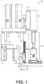
- FIG. 1 is a front view illustrating one example of a linear member gripping device according to the present embodiment.
- FIG. 2 is a side view illustrating one example of a linear member gripping device according to the present embodiment.
- linear member gripping device means a device that grips, one by one, multiple linear members obtained after various processings and supplied as an assembly.
- a lead wire as an electric wire is assumed as a linear member.
- any kind of linear member may be used.
- a linear member gripping device is described as follows based on FIG. 1 and FIG. 2 .
- a linear member gripping device 1A according to the present embodiment includes a first drive part 2, a second drive part 3, a first gripping member 4, a second gripping member 5, and a limitation part 6.
- the first gripping member 4 and the second gripping member 5 abut the linear member and grip the linear member.
- the first drive part 2 changes relative positions of the first gripping member 4 and the second gripping member 5 in a first direction being a direction in which the first gripping member 4 and the second gripping member 5 approach or depart from each other.
- the first direction is a direction perpendicular to a first gripping surface 4a and a second gripping surface 5a.
- the second drive part 3 changes the relative positions of the first gripping member 4 and the second gripping member 5 in a second direction perpendicular to the first direction.
- the second direction is a direction parallel to the first gripping surface 4a and the second gripping surface 5a.
- the first gripping surface 4a and the second gripping surface 5a do not have to be disposed completely parallel to each other, and may face each other while deviating by a predetermined angle from the parallel state within an allowable range.
- the first direction and the second direction do not have to be completely perpendicular to each other, and may have an angle deviating by a predetermined angle from the perpendicular state within an allowable range.
- first gripping member 4 and the second gripping member 5 driven by the first drive part 2 and the second drive part 3 have gripped multiple linear members
- one of the multiple linear members can be gripped by the first gripping member 4, the second gripping member 5, and the limitation part 6.
- FIG. 4 is an enlarged view illustrating the inside of a dotted line frame in FIG. 1 .
- the linear member gripping device 1A includes the first drive part 2, the second drive part 3, the first gripping member 4, the second gripping member 5, the limitation part 6, a first sliding part 7 and a second sliding part 8.
- the first gripping member 4 has the first gripping surface 4a that abuts the linear member to be gripped.
- the second gripping surface has the second gripping surface 5a facing the first gripping surface 4a, and has a protrusion 5b protruding toward the first gripping surface 4a from the second gripping surface 5a.
- a root side gripping surface 4b, a tip side gripping surface 4d, and a step surface 4c connecting the root side gripping surface 4b and the tip side gripping surface 4d are formed in order in a vertically downward direction.
- a distance A between the root side gripping surface 4b and the second gripping surface 5a is larger than a distance B between the tip side gripping surface 4d and the second gripping surface 5a.
- the first drive part 2 changes the relative positions of the first gripping member 4 and the second gripping member 5 in the first direction X perpendicular to the first gripping surface 4a and the second gripping surface 5a.
- the second drive part 3 changes the relative positions of the first gripping member 4 and the second gripping member 5 in the second direction Y parallel to the first gripping surface 4a and the second gripping surface 5a.
- the limitation part 6 limits movement of the linear member gripped between the first gripping member 4 and the second gripping member 5 toward the second direction Y at a predetermined limitation position (described later).
- the first sliding part 7 is a guide member for moving the relative positions of the first gripping member 4 and the second gripping member 5 toward the first direction X.
- the second sliding part 8 is a guide member for moving the relative positions of the first gripping member 4 and the second gripping member 5 toward the second direction Y.
- FIG. 5 is a schematic view illustrating an example of the shape of the protrusion 5b of a linear member gripping device according to the present embodiment. As illustrated in sign 101 of FIG. 5 , the protrusion 5b has a shape as follows.
- a straight line from a center point C in a section 50a of the linear member 50 to a contact point D between the first gripping surface 4a and the linear member 50 and a straight line from the center point C to a contact point E between the protrusion 5b (protruding surface 5c) and the linear member 50 form an angle ⁇ greater than 90 degrees and less than 180 degrees.
- the shape of the protrusion 5b is not particularly limited if the angle ⁇ is greater than 90 degrees and less than 180 degrees when the linear member 50 contacts the first gripping surface 4a and the protrusion 5b.
- Examples of the shape of the protrusion 5b may include a shape like a protrusion (protruding surface 5d) illustrated in sign 102 of FIG. 5 in which a sectional shape of the protrusion is substantially partially circular.
- the shape of the protrusion is not limited if the shape is not a shape (for example, a shape in which the linear member 50 is likely to contact at a position on a protruding surface like protruding surfaces 5f and 5e whose normal direction is inclined toward the second gripping surface 5a rather than the vertical direction) in which the angle ⁇ may be 90 degrees or less, as illustrated in signs 103 and 104 of FIG. 5 .
- the shape of the protrusion is appropriately determined according to the size of the major axis of the section 50a (or the type of the linear member 50).
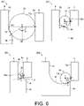
- FIG. 6 is a schematic view illustrating an example of the shape of the step surface 4c of a linear member gripping device according to the present embodiment.
- the step surface 4c has a shape as follows. As illustrated in sign 201 of FIG. 6 , when the linear member 50 contacts the second gripping surface 5a and the step surface 4c, a straight line from the center point C in the section 50a of the linear member 50 to a contact point F between the second gripping surface 5a and the linear member 50 and a straight line from the center point C to a contact point G between the step surface 4c and the linear member 50 form an angle ⁇ greater than 90 degrees and less than 180 degrees.
- the shape of the step surface 4c is not particularly limited if the angle ⁇ is greater than 90 degrees and less than 180 degrees when the linear member 50 contacts the second gripping surface 5a and the step surface 4c.
- Examples of the shape of the step surface 4c may include, for example, a shape like a step surface 4e illustrated in sign 202 of FIG. 6 in which a sectional shape of the step surface draws an arc.
- the shape of the step surface is not limited if the shape is not a shape (for example, a shape in which the linear member 50 is likely to contact at a position on a step surface like step surfaces 4g and 4f whose normal direction is inclined toward the root side gripping surface 4b rather than the vertical direction) in which the angle ⁇ may be 90 degrees or less, as illustrated in signs 203 and 204 of FIG. 6 .
- the shape of the step surface is appropriately determined according to the size of the major axis of the section 50a (or the type of the linear member 50).
- the first drive part 2, the second drive part 3, the first gripping member 4, the second gripping member 5, the first sliding part 7, and the second sliding part 8 are connected via each structural member (for example, structural members 9, 10, 12, 14 and 15).
- the limitation part 6 is provided, for example, on the root side of the root side gripping surface 4b in the first gripping member 4.
- FIG. 3 is a block view illustrating one example of a functional block of a control part included in the linear member gripping device 1A.
- the linear member gripping device 1A includes a control part 30.
- the control part 30 includes a central processing unit (CPU), a random access memory (RAM), a read only memory (ROM) or the like, and controls each component according to information processing.
- CPU central processing unit
- RAM random access memory
- ROM read only memory
- the control part 30 includes a detector 301, a recognition part 302 and a drive control part 303.
- the detector 301 is a functional block detecting a distance (for example, the distance A or the distance B in FIG. 4 ) between the first gripping surface 4a and the second gripping surface 5a (or the protruding surface 5c).
- the recognition part 302 is a functional block recognizing the number of the linear member gripped by the first gripping surface 4a and the second gripping surface 5a based on the distance detected.
- the detector 301 and the recognition part 302 may be configured to be provided in an external control device connected to the linear member gripping device 1A via a communication network. Examples of the external control device include a programmable logic controller (PLC) or an industrial PC (IPC).
- PLC programmable logic controller
- IPC industrial PC
- the drive control part 303 is a functional block driving the first drive part 2 and the second drive part 3.
- the drive control part 303 controls driving and stop of the first drive part 2 and the second drive part 3 in response to the processing of the detector 301 and the recognition part 302.
- FIG. 7 is a schematic view illustrating a flow of a series of operations of the linear member gripping device 1A according to the present embodiment.
- FIG. 7 illustrates only a configuration within the dotted line frame in FIG. 1 .
- a horizontal direction being a left-right direction as viewed toward the drawing sheet is taken as the first direction X
- a vertical direction being an up-down direction as viewed toward the drawing sheet is taken as the second direction Y.
- the multiple linear members are gripped by the two gripping members, by applying a gripping force toward the first direction X to the two gripping members by drive of the first drive part 2, the relative positions of the first gripping member 4 and the second gripping member 5 are brought closer to each other.
- the second gripping member 5 is driven vertically upward by the second drive part 3 so that the protrusion 5b approaches the vicinity (hereinafter referred to as a limitation position) of the limitation part 6 (signs 402 and 403).
- the multiple linear members By rubbing the multiple linear members together between the first gripping member 4 and the second gripping member 5, the multiple linear members are arranged in a line toward the second direction Y.
- the multiple linear members gripped between the first gripping member 4 and the second gripping member 5 move vertically upward while rolling on the second gripping surface 5a as the second gripping member 5 moves vertically upward.
- vertically downward movement of the linear member (section 50c) is limited by the protrusion 5b. Accordingly, the multiple linear members gripped by the two gripping members move upward without being released.
- the linear member (section 50a) closest to the limitation part 6 reaches the vicinity (limitation position) of an abutting surface 6a of the limitation part 6. Due to a balance between movement of the vertically upward driven second gripping member 5 toward the second direction Y and gripping force of the first gripping member 4 and the second gripping member 5 generated toward the first direction X, a distance between the two gripping members is widened, and the linear members (sections 50b and 50c) are released one by one vertically downward from the two gripping members (signs 404 and 405).
- the relative positions of the first gripping member 4 and the second gripping member 5 are driven vertically downward so that the protrusion 5b departs from the limitation position.
- the second gripping member 5 is driven and returns to the original position (the position of the second gripping member 5 illustrated in sign 401) before driving (signs 406 and 407).
- the section 50a gripped between the two gripping members moves vertically downward while rolling on the second gripping surface 5a as the second gripping member 5 is driven toward the second direction Y.
- the section 50a that has moved vertically downward contacts the step surface 4c.
- the first gripping member 4 and the second gripping member 5 gripping the linear member (section 50a) are driven so that the first gripping member 4 and the second gripping member 5 gripping the linear member move toward a direction (upward direction) of the root side in the second direction Y.
- the linear member (section 50a) is pulled to an upper part of the linear member gripping device 1A.
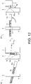
- FIG. 12 is a schematic view illustrating a state in which one linear member 53 provided with a terminal member 53a is gripped according to an operation example of a linear member gripping device according to the present embodiment.
- the left figures of signs 801 and 802 illustrate side views of the first gripping member 4 as viewed from a direction perpendicular to an extension direction of a linear member when the linear member is being gripped.
- the right figures of signs 801 and 802 illustrate front views of the first gripping member 4 and the second gripping member as viewed from the extension direction of the linear member when the linear member is being gripped. As illustrated in sign 801 of FIG.
- the linear member 53 is gripped by a protruding surface 5g of the protrusion 5b and the abutting surface 6a (not illustrated) of the limitation part 6. Accordingly, the linear member 53 can be gripped so as to be parallel to a substantially horizontal direction.
- the left figures of signs 501 to 503 illustrate side views of the first gripping member 4 as viewed from a direction perpendicular to an extension direction of a linear member when the linear member is being gripped.
- the right figures of signs 501 and 503 illustrate front views of the first gripping member 4 and the second gripping member as viewed from the extension direction of the linear member when the linear member is being gripped.
- the above entanglement of linear members can be released by the following operation.
- the second gripping member 5 is driven vertically downward.
- a linear member 51 in contact with the second gripping surface 5a rotates and moves vertically downward.
- a linear member 52 also rotates, and accordingly, the terminal member 52a also rotates.
- the hooking between the terminal member 51a and the terminal member 52a is released, and the linear member 51 and the linear member 52 are disentangled (sign 503).
- the second gripping member 5 is driven vertically downward. Since the linear member 52 moves vertically downward as the second gripping member 5 is driven, the linear member 52 is released from the two gripping members (sign 503).
- the number of the linear member gripped by the two gripping members by the series of operations from sign 401 to sign 405 is recognized as follows.
- the detector 301 detects the distance between the first gripping surface 4a and the second gripping surface 5a, and based on the distance detected, the recognition part 302 recognizes the number of the linear member gripped by the first gripping surface 4a and the second gripping surface 5a.
- described below is one example of a method for detecting the number of the linear member and recognition of the number of the linear member in an operation example of a linear member gripping device according to the present embodiment.
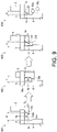
- FIG. 9 is a schematic view illustrating one example of a method for detecting the number of linear members in an operation example of the linear member gripping device 1A according to the present embodiment.
- the detector 301 detects a distance I between the first gripping surface 4a and the second gripping surface 5a, or distances H, J and K between the first gripping surface 4a and the protruding surface 5c.
- the recognition part 302 Based on the distance detected by the detector 301, the recognition part 302 recognizes the number of the linear member gripped by the first gripping surface 4a and the second gripping surface 5a (protruding surface 5c). For example, if the detector 301 detects that the distance is the distance H, the recognition part 302 recognizes that two linear members are being gripped. If the detector 301 detects that the distance is the distance I or the distance J, the recognition part 302 recognizes that one linear member is being gripped. If the detector 301 detects that the distance is the distance K, the recognition part 302 recognizes that no linear member is being gripped. According to the number of the linear member recognized by the recognition part 302, it is determined whether the gripping operation has succeeded or failed, and the following controls are performed. If it has succeeded, a transfer operation of the linear member is performed; if it has failed, the gripping operation is performed again.
- a device that enables the detection of each distance by the detector 301 is not particularly limited. For example, there may be mentioned a configuration in which a sensing result by a proximity sensor or a ray sensor is transmitted to the detector 301, and a configuration in which an encoder output or a cylinder sensor output of a drive motor that changes the relative positions of the first gripping member 4 and the second gripping member 5 in an X direction is transmitted to the detector 301.
- the recognition part 302 recognizes the number of the linear member gripped based on the distance detected by the detector 301.
- an output from a sensor capable of directly detecting the number of the linear member may be used.
- a sensing result by a proximity sensor or a photoelectric sensor may be transmitted to the recognition part 302, and the recognition part 302 may directly recognize the number of the linear member from the sensing result.
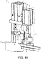
- FIG. 10 is a side view illustrating another example of a linear member gripping device according to the present embodiment.
- a linear member gripping device 1B may include, in addition to the configuration provided in the linear member gripping device 1A described in ⁇ 2, an insertion member 17, as illustrated in FIG. 10 .
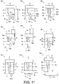
- FIG. 11 is a schematic view illustrating another example of a flow of a series of operations of the linear member gripping device 1B according to the present embodiment.
- the horizontal direction is taken as the first direction X
- the vertical up-down direction is taken as the second direction Y.
- the second gripping member 5 is driven in a direction departing from the limitation position. Then, after the second gripping member 5 has been driven in the direction in which the protrusion 5b departs from the limitation position, the second gripping member 5 is driven vertically downward. That is, the second drive part 3 drives the relative positions of the first gripping member 4 and the second gripping member 5 in the direction in which the protrusion 5b departs from the limitation position.
- the insertion member 17 is inserted into a predetermined position on the root side (upward direction) of the protrusion 5b at the moment after the driving (sign 708).
- the second drive part 3 lifts the first gripping member 4 and the second gripping member 5 vertically upward, causing the one linear member that is being gripped to move to a place of the next process (sign 709).
- the linear member indicated by 50b may also be lifted and moved.
- the linear member that is not to be gripped may be lifted and moved together with the linear member that is to be gripped.
- ⁇ 2 and ⁇ 4 an example is illustrated in which the second gripping member 5 is driven toward the second direction Y.
- a method for driving the first gripping member 4 and the second gripping member 5 is not limited thereto.
- an operation may be performed in which, by fixing the second gripping member 5 and driving the first gripping member 4 toward the second direction Y, one linear member is gripped from among multiple linear members.
- An operation may be performed in which, by driving the first gripping member and the second gripping member respectively toward the second direction Y, one linear member is gripped from among multiple linear members.
- ⁇ 2 and ⁇ 4 an operation example is illustrated in which, by driving the first gripping member 4 and the second gripping member 5 toward the first direction X so as to approach each other, multiple linear members are gripped.
- a method for driving the first gripping member 4 and the second gripping member 5 is not limited thereto.
- an operation may be performed in which, by fixing the first gripping member 4 and driving only the second gripping member 5 toward the first direction X, multiple linear members are gripped.
- An operation may be performed in which, by fixing the second gripping member 5 and driving only the second gripping member 5 toward the first direction X, multiple linear members are gripped.
- ⁇ 2 and ⁇ 4 an operation example is illustrated in which, by driving the second gripping member 5 toward the second direction Y, one linear member is left from multiple linear members.
- the driving direction for releasing multiple linear members from the two gripping members is not limited to the second direction.
- the first gripping member and the second gripping member are provided so as to extend in the vertical up-down direction.
- the first gripping member and the second gripping member may be provided so as to extend in the horizontal direction so that multiple linear members are released from the two gripping members in the first direction X.
- a linear member gripping device includes: a first gripping member, having a first gripping surface that abuts a linear member to be gripped; a second gripping member, having a second gripping surface that abuts the linear member and faces the first gripping surface, and having a protrusion protruding toward the first gripping surface from the second gripping surface; a first drive part, changing relative positions of the first gripping member and the second gripping member in a first direction being a direction in which the first gripping member and the second gripping member approach or depart from each other, and a second drive part, changing the relative positions of the first gripping member and the second gripping member in a second direction perpendicular to the first direction; and a limitation part, limiting movement of the linear member sandwiched between the first gripping member and the second gripping member toward the second direction at a predetermined limitation position.
- the second drive part drives the relative positions of the first gripping member and the second gripping member so that the protrusion approaches the limitation position.
- the first gripping member and the second gripping member can be driven so as to reduce the number of the multiple linear members gripped and leave only one linear member sandwiched between the first gripping member and the second gripping member.
- the second drive part drives the relative positions of the first gripping member and the second gripping member so that the protrusion approaches the limitation position
- the second drive part drives the relative positions of the first gripping member and the second gripping member in a direction in which the protrusion departs from the limitation position.
- a distance between the linear member gripped by the first gripping member and the second gripping member and another linear member that is not gripped can be increased.
- the first gripping surface includes a root side gripping surface, a tip side gripping surface, and a step surface connecting the root side gripping surface and the tip side gripping surface.
- a distance between the root side gripping surface and the second gripping surface is larger than a distance between the tip side gripping surface and the second gripping surface.
- the linear member since the first gripping surface has the step surface, by fitting the linear member to the step surface and the second gripping surface, movement of the linear member can be limited.
- a straight line from a center point in a section of the linear member to a contact point between the first gripping surface and the linear member and a straight line from the center point to a contact point between the protrusion and the linear member form an angle greater than 90 degrees and less than 180 degrees.
- movement of the linear member associated with the movement of the linear member can be limited.
- a straight line from a center point in a section of the linear member to a contact point between the second gripping surface and the linear member and a straight line from the center point to a contact point between the step surface and the linear member form an angle greater than 90 degrees and less than 180 degrees.
- movement of the linear member associated with the movement of the linear member can be limited.
- the first gripping member and the second gripping member gripping the linear member move toward a root side in the second direction.
- the linear member gripped by the first gripping member and the second gripping member can be pulled up from the linear member gripping device.
- an insertion member is further provided that is inserted into a predetermined position on the root side of the protrusion at a moment when the second drive part has driven the relative positions of the first gripping member and the second gripping member in the direction in which the protrusion departs from the limitation position.
- a recognition part is further provided that recognizes the number of the linear member gripped by the first gripping surface and the second gripping surface.
- the recognition part detects a distance between the first gripping surface and the second gripping surface, and recognizes the number of the linear member based on the distance detected.
- the number of the linear member can be recognized based on the distance between the first gripping surface and the second gripping surface that is relatively easy to detect.
Landscapes
- Engineering & Computer Science (AREA)
- Mechanical Engineering (AREA)
- Robotics (AREA)
- Health & Medical Sciences (AREA)
- General Health & Medical Sciences (AREA)
- Orthopedic Medicine & Surgery (AREA)
- Manufacturing & Machinery (AREA)
- Manipulator (AREA)
- Wire Processing (AREA)
Abstract
Description
- The present invention relates to a linear member gripping device.
- Linear members such as lead wires obtained after various processes are collected to form a linear member assembly. After that, the linear members are separated one by one from the linear member assembly, and the linear members after separation are sequentially supplied to a subsequent processing process.
- As a technique for separating the linear members one by one from the linear member assembly, for example,
Patent Document 1 describes a wire supply device as follows. The wire supply device includes an accommodation part accommodating a wire, a gripping part gripping and moving the wire, and a movable part displacing the accommodation part. The accommodation part has a first accommodation piece and a second accommodation piece facing each other with the wire as a boundary. A deviation gap between the two accommodation pieces is reduced as approaching one direction side, and an opening is provided on the one direction side. The gripping part has a first gripping piece and a second gripping piece facing each other. A deviation gap between the two gripping pieces is reduced as approaching one direction side, and the wire exposed from the opening is gripped by being accommodated in the deviation gap. The movable part displaces the accommodation part so as to deviate the opening from the gripping part. - Patent Document 1: Japanese Patent Publication "
Japanese Patent Laid-open No. 2013-202649 (published on October 7, 2013 - In the above-mentioned conventional technique, the gripping part is moved toward the opening, and the wire is sandwiched in the deviation gap between the two gripping pieces of the gripping part. The gripping part has a structure in which the deviation gap between the two gripping pieces is reduced toward a side close to the roots of the two gripping pieces and is increased toward a side opposite the roots of the two gripping pieces. Since the two gripping pieces have the structure, among multiple wires accommodated in the accommodation part and exposed from the opening, there is a risk that it may not be possible to grip a single wire in the deviation gap between the two gripping pieces and multiple wires may be gripped. Therefore, there has been a demand for a device capable of reliably gripping a single wire. One aspect of the present invention realizes a device capable of reliably gripping a single linear member.
- In order to solve the aforementioned problems, a linear member gripping device according to one aspect of the present invention includes: a first gripping member, having a first gripping surface that abuts a linear member to be gripped; a second gripping member, having a second gripping surface that abuts the linear member and faces the first gripping surface, and having a protrusion protruding toward the first gripping surface from the second gripping surface; a first drive part, changing relative positions of the first gripping member and the second gripping member in a first direction being a direction in which the first gripping member and the second gripping member approach or depart from each other, and a second drive part, changing the relative positions of the first gripping member and the second gripping member in a second direction perpendicular to the first direction; and a limitation part, limiting movement of the linear member sandwiched between the first gripping member and the second gripping member toward the second direction at a predetermined limitation position.
- According to one aspect of the present invention, a device is realized capable of reliably gripping a single linear member.
-
-
FIG. 1 is a front view illustrating one example of a linear member gripping device according to one embodiment of the present invention. -
FIG. 2 is a side view illustrating one example of a linear member gripping device according to one embodiment of the present invention. -
FIG. 3 is a block view illustrating one example of a functional block of a control part included in a linear member gripping device according to one embodiment of the present invention. -
FIG. 4 is an enlarged view illustrating the inside of a dotted line frame inFIG. 1 . -
FIG. 5 is a schematic view illustrating an example of the shape of a protrusion of a linear member gripping device according to one embodiment of the present invention. -
FIG. 6 is a schematic view illustrating an example of the shape of a step surface of a linear member gripping device according to one embodiment of the present invention. -
FIG. 7 is a schematic view illustrating a flow of a series of operations of a linear member gripping device according to one embodiment of the present invention. -
FIG. 8 is a schematic view illustrating a state in which one linear member is gripped according to an operation example of a linear member gripping device according to one embodiment of the present invention. -
FIG. 9 is a schematic view illustrating one example of a method for detecting the number of linear members in an operation example of a linear member gripping device according to one embodiment of the present invention. -
FIG. 10 is a side view illustrating another example of a linear member gripping device according to one embodiment of the present invention. -
FIG. 11 is a schematic view illustrating another example of a flow of a series of operations of a linear member gripping device according to one embodiment of the present invention. -
FIG. 12 is a schematic view illustrating a state in which one linear member provided with a terminal member is gripped according to an operation example of a linear member gripping device according to one embodiment of the present invention. - An embodiment (hereinafter also written as "the present embodiment") according to one aspect of the present invention is hereinafter described based on the drawings.
- A linear member gripping device in a scene to which the present invention is applied is described with reference to
FIG. 1 andFIG. 2 .FIG. 1 is a front view illustrating one example of a linear member gripping device according to the present embodiment.FIG. 2 is a side view illustrating one example of a linear member gripping device according to the present embodiment. - In the present specification, the term "linear member gripping device" means a device that grips, one by one, multiple linear members obtained after various processings and supplied as an assembly. In the present embodiment, a lead wire as an electric wire is assumed as a linear member. However, any kind of linear member may be used.
- A linear member gripping device according to the present embodiment is described as follows based on
FIG. 1 andFIG. 2 . A linearmember gripping device 1A according to the present embodiment includes afirst drive part 2, asecond drive part 3, afirst gripping member 4, asecond gripping member 5, and alimitation part 6. - The first gripping
member 4 and the second grippingmember 5 abut the linear member and grip the linear member. As illustrated inFIG. 4 , thefirst drive part 2 changes relative positions of thefirst gripping member 4 and the second grippingmember 5 in a first direction being a direction in which the first grippingmember 4 and the second grippingmember 5 approach or depart from each other. In this example, the first direction is a direction perpendicular to afirst gripping surface 4a and asecond gripping surface 5a. Thesecond drive part 3 changes the relative positions of thefirst gripping member 4 and thesecond gripping member 5 in a second direction perpendicular to the first direction. In this example, the second direction is a direction parallel to thefirst gripping surface 4a and thesecond gripping surface 5a. Thefirst gripping surface 4a and thesecond gripping surface 5a do not have to be disposed completely parallel to each other, and may face each other while deviating by a predetermined angle from the parallel state within an allowable range. The first direction and the second direction do not have to be completely perpendicular to each other, and may have an angle deviating by a predetermined angle from the perpendicular state within an allowable range. - After the first gripping
member 4 and thesecond gripping member 5 driven by thefirst drive part 2 and thesecond drive part 3 have gripped multiple linear members, by further driving each gripping member by each drive part, one of the multiple linear members can be gripped by the first grippingmember 4, thesecond gripping member 5, and thelimitation part 6. - One example of a linear member gripping device according to the present embodiment is described with reference to
FIG. 1 ,FIG. 2 andFIG. 4 . Here,FIG. 4 is an enlarged view illustrating the inside of a dotted line frame inFIG. 1 . - In the example of
FIG. 1 andFIG. 2 , the linearmember gripping device 1A according to the present embodiment includes thefirst drive part 2, thesecond drive part 3, thefirst gripping member 4, thesecond gripping member 5, thelimitation part 6, a first slidingpart 7 and a secondsliding part 8. - The first gripping
member 4 has thefirst gripping surface 4a that abuts the linear member to be gripped. The second gripping surface has thesecond gripping surface 5a facing thefirst gripping surface 4a, and has aprotrusion 5b protruding toward thefirst gripping surface 4a from thesecond gripping surface 5a. - On the
first gripping surface 4a, a rootside gripping surface 4b, a tipside gripping surface 4d, and astep surface 4c connecting the rootside gripping surface 4b and the tipside gripping surface 4d are formed in order in a vertically downward direction. A distance A between the rootside gripping surface 4b and thesecond gripping surface 5a is larger than a distance B between the tipside gripping surface 4d and thesecond gripping surface 5a. - The
first drive part 2 changes the relative positions of thefirst gripping member 4 and thesecond gripping member 5 in the first direction X perpendicular to thefirst gripping surface 4a and thesecond gripping surface 5a. Thesecond drive part 3 changes the relative positions of the first grippingmember 4 and the second grippingmember 5 in the second direction Y parallel to the firstgripping surface 4a and the secondgripping surface 5a. - The
limitation part 6 limits movement of the linear member gripped between the first grippingmember 4 and the second grippingmember 5 toward the second direction Y at a predetermined limitation position (described later). - The first sliding
part 7 is a guide member for moving the relative positions of the first grippingmember 4 and the second grippingmember 5 toward the first direction X. The second slidingpart 8 is a guide member for moving the relative positions of the first grippingmember 4 and the second grippingmember 5 toward the second direction Y. - Here, the shape of the
protrusion 5b is described below.FIG. 5 is a schematic view illustrating an example of the shape of theprotrusion 5b of a linear member gripping device according to the present embodiment. As illustrated insign 101 ofFIG. 5 , theprotrusion 5b has a shape as follows. When alinear member 50 contacts the firstgripping surface 4a and theprotrusion 5b (protrudingsurface 5c), a straight line from a center point C in asection 50a of thelinear member 50 to a contact point D between the firstgripping surface 4a and thelinear member 50 and a straight line from the center point C to a contact point E between theprotrusion 5b (protrudingsurface 5c) and thelinear member 50 form an angle α greater than 90 degrees and less than 180 degrees. - The shape of the
protrusion 5b is not particularly limited if the angle α is greater than 90 degrees and less than 180 degrees when thelinear member 50 contacts the firstgripping surface 4a and theprotrusion 5b. Examples of the shape of theprotrusion 5b may include a shape like a protrusion (protrudingsurface 5d) illustrated insign 102 ofFIG. 5 in which a sectional shape of the protrusion is substantially partially circular. In other words, the shape of the protrusion is not limited if the shape is not a shape (for example, a shape in which thelinear member 50 is likely to contact at a position on a protruding surface like protrudingsurfaces gripping surface 5a rather than the vertical direction) in which the angle α may be 90 degrees or less, as illustrated insigns FIG. 5 . In consideration of the above relationship, the shape of the protrusion is appropriately determined according to the size of the major axis of thesection 50a (or the type of the linear member 50). - The shape of the
step surface 4c is described below.FIG. 6 is a schematic view illustrating an example of the shape of thestep surface 4c of a linear member gripping device according to the present embodiment. Thestep surface 4c has a shape as follows. As illustrated insign 201 ofFIG. 6 , when thelinear member 50 contacts the secondgripping surface 5a and thestep surface 4c, a straight line from the center point C in thesection 50a of thelinear member 50 to a contact point F between the secondgripping surface 5a and thelinear member 50 and a straight line from the center point C to a contact point G between thestep surface 4c and thelinear member 50 form an angle β greater than 90 degrees and less than 180 degrees. - The shape of the
step surface 4c is not particularly limited if the angle β is greater than 90 degrees and less than 180 degrees when thelinear member 50 contacts the secondgripping surface 5a and thestep surface 4c. Examples of the shape of thestep surface 4c may include, for example, a shape like astep surface 4e illustrated insign 202 ofFIG. 6 in which a sectional shape of the step surface draws an arc. In other words, the shape of the step surface is not limited if the shape is not a shape (for example, a shape in which thelinear member 50 is likely to contact at a position on a step surface like step surfaces 4g and 4f whose normal direction is inclined toward the rootside gripping surface 4b rather than the vertical direction) in which the angle β may be 90 degrees or less, as illustrated insigns FIG. 6 . In consideration of the above relationship, the shape of the step surface is appropriately determined according to the size of the major axis of thesection 50a (or the type of the linear member 50). - The
first drive part 2, thesecond drive part 3, the first grippingmember 4, the second grippingmember 5, the first slidingpart 7, and the second slidingpart 8 are connected via each structural member (for example,structural members limitation part 6 is provided, for example, on the root side of the rootside gripping surface 4b in the first grippingmember 4. - One example of a functional block of a control part included in a linear member gripping device according to the present embodiment is described with reference to
FIG. 3. FIG. 3 is a block view illustrating one example of a functional block of a control part included in the linearmember gripping device 1A. - In the example of
FIG. 3 , the linearmember gripping device 1A according to the present embodiment includes acontrol part 30. Thecontrol part 30 includes a central processing unit (CPU), a random access memory (RAM), a read only memory (ROM) or the like, and controls each component according to information processing. - The
control part 30 includes adetector 301, arecognition part 302 and adrive control part 303. Thedetector 301 is a functional block detecting a distance (for example, the distance A or the distance B inFIG. 4 ) between the firstgripping surface 4a and the secondgripping surface 5a (or the protrudingsurface 5c). Therecognition part 302 is a functional block recognizing the number of the linear member gripped by the firstgripping surface 4a and the secondgripping surface 5a based on the distance detected. Thedetector 301 and therecognition part 302 may be configured to be provided in an external control device connected to the linearmember gripping device 1A via a communication network. Examples of the external control device include a programmable logic controller (PLC) or an industrial PC (IPC). - The
drive control part 303 is a functional block driving thefirst drive part 2 and thesecond drive part 3. Thedrive control part 303 controls driving and stop of thefirst drive part 2 and thesecond drive part 3 in response to the processing of thedetector 301 and therecognition part 302. - An operation example of a linear member gripping device according to the present embodiment is described with reference to
FIG. 7. FIG. 7 is a schematic view illustrating a flow of a series of operations of the linearmember gripping device 1A according to the present embodiment. For convenience of description,FIG. 7 illustrates only a configuration within the dotted line frame inFIG. 1 . InFIG. 7 , a horizontal direction being a left-right direction as viewed toward the drawing sheet is taken as the first direction X, and a vertical direction being an up-down direction as viewed toward the drawing sheet is taken as the second direction Y. - First, multiple linear members obtained after various processings are collected. When the collected linear members are supplied to the linear
member gripping device 1A, the first grippingmember 4 and the second grippingmember 5 are driven by thefirst drive part 2 toward the first direction X so that the relative positions of the first grippingmember 4 and the second grippingmember 5 are brought close to each other. Accordingly, multiple linear members (sections - When the multiple linear members are gripped by the two gripping members, by applying a gripping force toward the first direction X to the two gripping members by drive of the
first drive part 2, the relative positions of the first grippingmember 4 and the second grippingmember 5 are brought closer to each other. The secondgripping member 5 is driven vertically upward by thesecond drive part 3 so that theprotrusion 5b approaches the vicinity (hereinafter referred to as a limitation position) of the limitation part 6 (signs 402 and 403). By rubbing the multiple linear members together between the first grippingmember 4 and the second grippingmember 5, the multiple linear members are arranged in a line toward the second direction Y. The multiple linear members gripped between the first grippingmember 4 and the second grippingmember 5 move vertically upward while rolling on the secondgripping surface 5a as the second grippingmember 5 moves vertically upward. During the movement, vertically downward movement of the linear member (section 50c) is limited by theprotrusion 5b. Accordingly, the multiple linear members gripped by the two gripping members move upward without being released. - When the multiple linear members continue to move upward, among the multiple linear members arranged in a line, the linear member (
section 50a) closest to thelimitation part 6 reaches the vicinity (limitation position) of anabutting surface 6a of thelimitation part 6. Due to a balance between movement of the vertically upward driven second grippingmember 5 toward the second direction Y and gripping force of the first grippingmember 4 and the second grippingmember 5 generated toward the first direction X, a distance between the two gripping members is widened, and the linear members (sections signs 404 and 405). At this time, upward movement of the second grippingmember 5 is stopped by the drive control part so that the length of the second gripping surface is reserved to the extent that one linear member is sandwiched between the two gripping members. Hence, only one linear member is left between the two gripping members. - After only one linear member is left between the two gripping members, the relative positions of the first gripping
member 4 and the second grippingmember 5 are driven vertically downward so that theprotrusion 5b departs from the limitation position. Specifically, the second grippingmember 5 is driven and returns to the original position (the position of the second grippingmember 5 illustrated in sign 401) before driving (signs 406 and 407). At this time, thesection 50a gripped between the two gripping members moves vertically downward while rolling on the secondgripping surface 5a as the second grippingmember 5 is driven toward the second direction Y. Thesection 50a that has moved vertically downward contacts thestep surface 4c. By fitting the linear member (section 50a) to thestep surface 4c, the rootside gripping surface 4b and the secondgripping surface 5a, vertically downward movement of thesection 50a is limited. - After the
second drive part 3 has driven the relative positions of the first grippingmember 4 and the second grippingmember 5 in the direction in which theprotrusion 5b departs from the limitation position, the first grippingmember 4 and the second grippingmember 5 gripping the linear member (section 50a) are driven so that the first grippingmember 4 and the second grippingmember 5 gripping the linear member move toward a direction (upward direction) of the root side in the second direction Y. By this movement, the linear member (section 50a) is pulled to an upper part of the linearmember gripping device 1A. - In a series of operations from
sign 401 to sign 407, basically, only one linear member is gripped. However, there may be a situation where the possibility that two or more linear members remain is not zero. In this case, for example, if the steps fromsign 403 to sign 407 are executed twice, the possibility that two or more linear members remain can be made almost zero. - In the following, an example of a state in which one linear member is gripped according to an operation example according to the present embodiment is described with reference to
FIG. 12. FIG. 12 is a schematic view illustrating a state in which onelinear member 53 provided with aterminal member 53a is gripped according to an operation example of a linear member gripping device according to the present embodiment. The left figures ofsigns member 4 as viewed from a direction perpendicular to an extension direction of a linear member when the linear member is being gripped. The right figures ofsigns member 4 and the second gripping member as viewed from the extension direction of the linear member when the linear member is being gripped. As illustrated insign 801 ofFIG. 12 , first, by sandwiching onelinear member 53 by the first grippingmember 4 and the second grippingmember 5 from the left-right direction, inclination of thelinear member 53 in the left-right direction is eliminated. After the onelinear member 53 has been sandwiched by the first grippingmember 4 and the second grippingmember 5, as illustrated insign 802 ofFIG. 12 , the sandwichedlinear member 53 is lifted to the limitation part 6 (not illustrated), thereby eliminating the inclination of thelinear member 53 in the up-down direction. - Here, in the linear
member gripping device 1A according to the present embodiment, as illustrated insign 802 ofFIG. 12 , thelinear member 53 is gripped by a protrudingsurface 5g of theprotrusion 5b and theabutting surface 6a (not illustrated) of thelimitation part 6. Accordingly, thelinear member 53 can be gripped so as to be parallel to a substantially horizontal direction. - An example of a state in which one linear member is gripped according to an operation example according to the present embodiment is described below with reference to
FIG. 8 . The left figures ofsigns 501 to 503 illustrate side views of the first grippingmember 4 as viewed from a direction perpendicular to an extension direction of a linear member when the linear member is being gripped. The right figures ofsigns member 4 and the second gripping member as viewed from the extension direction of the linear member when the linear member is being gripped. - In the case where various members (such as, for example,
terminal members FIG. 8 , since the members are hooked to each other as illustrated insign 501, the linear members may get entangled with each other. - In contrast, in the linear
member gripping device 1A according to the present embodiment, the above entanglement of linear members can be released by the following operation. First, as illustrated insign 502, the second grippingmember 5 is driven vertically downward. As the second grippingmember 5 moves vertically downward, alinear member 51 in contact with the secondgripping surface 5a rotates and moves vertically downward. Due to the movement, alinear member 52 also rotates, and accordingly, theterminal member 52a also rotates. Hence, the hooking between theterminal member 51a and theterminal member 52a is released, and thelinear member 51 and thelinear member 52 are disentangled (sign 503). - After that, the second gripping
member 5 is driven vertically downward. Since thelinear member 52 moves vertically downward as the second grippingmember 5 is driven, thelinear member 52 is released from the two gripping members (sign 503). - In the operation example illustrated in
FIG. 7 , in the case where no linear member is left between the two gripping members by the series of operations fromsign 401 to sign 405, by performing the series of operations fromsign 401 to sign 405 again, it is possible to leave only one linear member between the two gripping members. - The number of the linear member gripped by the two gripping members by the series of operations from
sign 401 to sign 405 is recognized as follows. Thedetector 301 detects the distance between the firstgripping surface 4a and the secondgripping surface 5a, and based on the distance detected, therecognition part 302 recognizes the number of the linear member gripped by the firstgripping surface 4a and the secondgripping surface 5a. Here, described below is one example of a method for detecting the number of the linear member and recognition of the number of the linear member in an operation example of a linear member gripping device according to the present embodiment. -
FIG. 9 is a schematic view illustrating one example of a method for detecting the number of linear members in an operation example of the linearmember gripping device 1A according to the present embodiment. As illustrated insigns 601 to 604 ofFIG. 9 , thedetector 301 detects a distance I between the firstgripping surface 4a and the secondgripping surface 5a, or distances H, J and K between the firstgripping surface 4a and the protrudingsurface 5c. - Based on the distance detected by the
detector 301, therecognition part 302 recognizes the number of the linear member gripped by the firstgripping surface 4a and the secondgripping surface 5a (protrudingsurface 5c). For example, if thedetector 301 detects that the distance is the distance H, therecognition part 302 recognizes that two linear members are being gripped. If thedetector 301 detects that the distance is the distance I or the distance J, therecognition part 302 recognizes that one linear member is being gripped. If thedetector 301 detects that the distance is the distance K, therecognition part 302 recognizes that no linear member is being gripped. According to the number of the linear member recognized by therecognition part 302, it is determined whether the gripping operation has succeeded or failed, and the following controls are performed. If it has succeeded, a transfer operation of the linear member is performed; if it has failed, the gripping operation is performed again. - A device that enables the detection of each distance by the
detector 301 is not particularly limited. For example, there may be mentioned a configuration in which a sensing result by a proximity sensor or a ray sensor is transmitted to thedetector 301, and a configuration in which an encoder output or a cylinder sensor output of a drive motor that changes the relative positions of the first grippingmember 4 and the second grippingmember 5 in an X direction is transmitted to thedetector 301. - In the above example, the
recognition part 302 recognizes the number of the linear member gripped based on the distance detected by thedetector 301. However, an output from a sensor capable of directly detecting the number of the linear member may be used. For example, a sensing result by a proximity sensor or a photoelectric sensor may be transmitted to therecognition part 302, and therecognition part 302 may directly recognize the number of the linear member from the sensing result. - The embodiments of the present invention have been described in detail as above. However, the above description is merely an example of the present invention in all respects. It goes without saying that various improvements or modifications can be made without departing from the scope of the present invention. For instance, the following changes are possible. In the following, the same components as those in the above embodiments are denoted by the same reference numerals, and description of the same points as those in the above embodiments are omitted as appropriate. The following modifications may be combined as appropriate.
-
FIG. 10 is a side view illustrating another example of a linear member gripping device according to the present embodiment. A linearmember gripping device 1B may include, in addition to the configuration provided in the linearmember gripping device 1A described in §2, aninsertion member 17, as illustrated inFIG. 10 . - In the following, an example of operation of the linear
member gripping device 1B including theinsertion member 17 is described with reference toFIG. 11. FIG. 11 is a schematic view illustrating another example of a flow of a series of operations of the linearmember gripping device 1B according to the present embodiment. Here, inFIG. 11 , the horizontal direction is taken as the first direction X, and the vertical up-down direction is taken as the second direction Y. - In an operation example in which the collected linear members have been supplied to the linear
member gripping device 1B, since the operations illustrated insigns 701 to 707 ofFIG. 11 are the same as the operations illustrated insigns 401 to 407 illustrated inFIG. 7 , the description thereof will be omitted herein. As illustrated insign 706 and the like inFIG. 11 , the second grippingmember 5 is driven in a direction departing from the limitation position. Then, after the second grippingmember 5 has been driven in the direction in which theprotrusion 5b departs from the limitation position, the second grippingmember 5 is driven vertically downward. That is, thesecond drive part 3 drives the relative positions of the first grippingmember 4 and the second grippingmember 5 in the direction in which theprotrusion 5b departs from the limitation position. After that, theinsertion member 17 is inserted into a predetermined position on the root side (upward direction) of theprotrusion 5b at the moment after the driving (sign 708). After that, thesecond drive part 3 lifts the first grippingmember 4 and the second grippingmember 5 vertically upward, causing the one linear member that is being gripped to move to a place of the next process (sign 709). - Here, if the
insertion member 17 is not inserted when a linear member (linear member to be gripped) indicated by 50a and a linear member (linear member not to be gripped) indicated by 50b get entangled, in the step ofsign 709, the linear member indicated by 50b may also be lifted and moved. In contrast, by inserting theinsertion member 17 into the predetermined position as described above, it can be prevented that the linear member that is not to be gripped may be lifted and moved together with the linear member that is to be gripped. - In §2 and §4, an example is illustrated in which the second gripping
member 5 is driven toward the second direction Y. However, a method for driving the first grippingmember 4 and the second grippingmember 5 is not limited thereto. For example, an operation may be performed in which, by fixing the second grippingmember 5 and driving the first grippingmember 4 toward the second direction Y, one linear member is gripped from among multiple linear members. An operation may be performed in which, by driving the first gripping member and the second gripping member respectively toward the second direction Y, one linear member is gripped from among multiple linear members. - In §2 and §4, an operation example is illustrated in which, by driving the first gripping
member 4 and the second grippingmember 5 toward the first direction X so as to approach each other, multiple linear members are gripped. However, a method for driving the first grippingmember 4 and the second grippingmember 5 is not limited thereto. For example, an operation may be performed in which, by fixing the first grippingmember 4 and driving only the second grippingmember 5 toward the first direction X, multiple linear members are gripped. An operation may be performed in which, by fixing the second grippingmember 5 and driving only the second grippingmember 5 toward the first direction X, multiple linear members are gripped. - Further, in §2 and §4, an operation example is illustrated in which, by driving the second gripping
member 5 toward the second direction Y, one linear member is left from multiple linear members. However, the driving direction for releasing multiple linear members from the two gripping members is not limited to the second direction. Specifically, in the linear member gripping device illustrated inFIG. 2 and the like, the first gripping member and the second gripping member are provided so as to extend in the vertical up-down direction. In contrast, the first gripping member and the second gripping member may be provided so as to extend in the horizontal direction so that multiple linear members are released from the two gripping members in the first direction X. - A linear member gripping device according to one aspect of the present invention includes: a first gripping member, having a first gripping surface that abuts a linear member to be gripped; a second gripping member, having a second gripping surface that abuts the linear member and faces the first gripping surface, and having a protrusion protruding toward the first gripping surface from the second gripping surface; a first drive part, changing relative positions of the first gripping member and the second gripping member in a first direction being a direction in which the first gripping member and the second gripping member approach or depart from each other, and a second drive part, changing the relative positions of the first gripping member and the second gripping member in a second direction perpendicular to the first direction; and a limitation part, limiting movement of the linear member sandwiched between the first gripping member and the second gripping member toward the second direction at a predetermined limitation position.
- According to the aforementioned configuration, after the first gripping member and the second gripping member driven by the first drive part and the second drive part have gripped multiple linear members, by further driving each gripping member by each drive part, one of the linear members can be gripped by the first gripping member, the second gripping member, and the limitation part. Therefore, a device capable of reliably gripping a single linear member is realized.
- In one embodiment, in the linear member gripping device, after the first drive part drives the relative positions of the first gripping member and the second gripping member to approach each other, the second drive part drives the relative positions of the first gripping member and the second gripping member so that the protrusion approaches the limitation position.
- According to the aforementioned configuration, the first gripping member and the second gripping member can be driven so as to reduce the number of the multiple linear members gripped and leave only one linear member sandwiched between the first gripping member and the second gripping member.
- In one embodiment, after the second drive part drives the relative positions of the first gripping member and the second gripping member so that the protrusion approaches the limitation position, the second drive part drives the relative positions of the first gripping member and the second gripping member in a direction in which the protrusion departs from the limitation position.
- According to the aforementioned configuration, a distance between the linear member gripped by the first gripping member and the second gripping member and another linear member that is not gripped can be increased.
- In one embodiment, in the linear member gripping device, the first gripping surface includes a root side gripping surface, a tip side gripping surface, and a step surface connecting the root side gripping surface and the tip side gripping surface. A distance between the root side gripping surface and the second gripping surface is larger than a distance between the tip side gripping surface and the second gripping surface.
- According to the aforementioned configuration, since the first gripping surface has the step surface, by fitting the linear member to the step surface and the second gripping surface, movement of the linear member can be limited.
- In one embodiment, in the linear member gripping device, when the linear member contacts the first gripping surface and the protrusion, a straight line from a center point in a section of the linear member to a contact point between the first gripping surface and the linear member and a straight line from the center point to a contact point between the protrusion and the linear member form an angle greater than 90 degrees and less than 180 degrees.
- According to the aforementioned configuration, movement of the linear member associated with the movement of the linear member can be limited.
- In one embodiment, when the linear member contacts the second gripping surface and the step surface, a straight line from a center point in a section of the linear member to a contact point between the second gripping surface and the linear member and a straight line from the center point to a contact point between the step surface and the linear member form an angle greater than 90 degrees and less than 180 degrees.
- According to the aforementioned configuration, movement of the linear member associated with the movement of the linear member can be limited.
- In one embodiment, after the second drive part drives the relative positions of the first gripping member and the second gripping member in the direction in which the protrusion departs from the limitation position, the first gripping member and the second gripping member gripping the linear member move toward a root side in the second direction.
- According to the aforementioned configuration, the linear member gripped by the first gripping member and the second gripping member can be pulled up from the linear member gripping device.
- In one embodiment, an insertion member is further provided that is inserted into a predetermined position on the root side of the protrusion at a moment when the second drive part has driven the relative positions of the first gripping member and the second gripping member in the direction in which the protrusion departs from the limitation position.
- According to the aforementioned configuration, by inserting the insertion member into the predetermined position, it can be prevented that the linear member that is not to be gripped may be lifted and moved together with the linear member that is to be gripped.
- In one embodiment, a recognition part is further provided that recognizes the number of the linear member gripped by the first gripping surface and the second gripping surface.
- According to the aforementioned configuration, by recognizing the number of the linear member gripped by the first gripping surface and the second gripping surface, a device capable of reliably gripping one linear member is realized.
- In one embodiment, the recognition part detects a distance between the first gripping surface and the second gripping surface, and recognizes the number of the linear member based on the distance detected.
- According to the aforementioned configuration, the number of the linear member can be recognized based on the distance between the first gripping surface and the second gripping surface that is relatively easy to detect.
- The present invention is not limited to the embodiments described above, and may be modified in various ways within the scope of the claims. An embodiment derived from a proper combination of technical means disclosed in respective different embodiments is also encompassed in the technical scope of the present invention.
-
- 1A, 1B: linear member gripping device
- 2: first drive part
- 3: second drive part
- 4: first gripping member
- 4a: first gripping surface
- 4b: root side gripping surface
- 4c, 4e, 4f, 4g: step surface
- 4d: tip side gripping surface
- 5: second gripping member
- 5a: second gripping surface
- 5b: protrusion
- 5d, 5e, 5f, 5g: protruding surface
- 6: limitation part
- 6a: abutting surface (limitation position)
- 7: first sliding part
- 8: second sliding part
- 17: insertion member
- 50, 51, 52, 53: linear member
- A: distance between root side gripping surface and second gripping surface
- B: distance between tip side gripping surface and second gripping surface
- C: center point
- D: contact point between first gripping surface and linear member
- E: contact point between protrusion and linear member
- F: contact point between second gripping surface and linear member
- G: contact point between step surface and linear member
- α: angle
- β: angle
Claims (10)
- A linear member gripping device, comprising:a first gripping member, having a first gripping surface that abuts a linear member to be gripped;a second gripping member, having a second gripping surface that abuts the linear member and faces the first gripping surface, and having a protrusion protruding toward the first gripping surface from the second gripping surface;a first drive part, changing relative positions of the first gripping member and the second gripping member in a first direction being a direction in which the first gripping member and the second gripping member approach or depart from each other, and a second drive part, changing the relative positions of the first gripping member and the second gripping member in a second direction perpendicular to the first direction; anda limitation part, limiting movement of the linear member sandwiched between the first gripping member and the second gripping member toward the second direction at a predetermined limitation position.
- The linear member gripping device according to claim 1, whereinafter the first drive part drives the relative positions of the first gripping member and the second gripping member to approach each other,the second drive part drives the relative positions of the first gripping member and the second gripping member so that the protrusion approaches the limitation position.
- The linear member gripping device according to claim 2, wherein
after the second drive part drives the relative positions of the first gripping member and the second gripping member so that the protrusion approaches the limitation position, the second drive part drives the relative positions of the first gripping member and the second gripping member in a direction in which the protrusion departs from the limitation position. - The linear member gripping device according to any one of claims 1 to 3, whereinthe first gripping surface comprises a root side gripping surface, a tip side gripping surface, and a step surface connecting the root side gripping surface and the tip side gripping surface;a distance between the root side gripping surface and the second gripping surface is larger than a distance between the tip side gripping surface and the second gripping surface.
- The linear member gripping device according to claim 1 or 2, wherein
when the linear member contacts the first gripping surface and the protrusion, a straight line from a center point in a section of the linear member to a contact point between the first gripping surface and the linear member and a straight line from the center point to a contact point between the protrusion and the linear member form an angle greater than 90 degrees and less than 180 degrees. - The linear member gripping device according to claim 4, wherein
when the linear member contacts the second gripping surface and the step surface, a straight line from a center point in a section of the linear member to a contact point between the second gripping surface and the linear member and a straight line from the center point to a contact point between the step surface and the linear member form an angle greater than 90 degrees and less than 180 degrees. - The linear member gripping device according to claim 3, wherein
after the second drive part drives the relative positions of the first gripping member and the second gripping member in the direction in which the protrusion departs from the limitation position, the first gripping member and the second gripping member gripping the linear member move toward a root side in the second direction. - The linear member gripping device according to claim 7, further comprising an insertion member that is inserted into a predetermined position on the root side of the protrusion at a moment when the second drive part has driven the relative positions of the first gripping member and the second gripping member in the direction in which the protrusion departs from the limitation position.
- The linear member gripping device according to any one of claims 1 to 8, further comprising a recognition part recognizing number of the linear member gripped by the first gripping surface and the second gripping surface.
- The linear member gripping device according to claim 9, wherein
the recognition part detects a distance between the first gripping surface and the second gripping surface, and recognizes the number of the linear member based on the distance detected.
Applications Claiming Priority (2)
| Application Number | Priority Date | Filing Date | Title |
|---|---|---|---|
| JP2019174677A JP7388089B2 (en) | 2019-09-25 | 2019-09-25 | Linear member gripping device |
| PCT/JP2020/032590 WO2021059863A1 (en) | 2019-09-25 | 2020-08-28 | Linear member gripping device |
Publications (2)
| Publication Number | Publication Date |
|---|---|
| EP4035793A1 true EP4035793A1 (en) | 2022-08-03 |
| EP4035793A4 EP4035793A4 (en) | 2023-10-18 |
Family
ID=75156284
Family Applications (1)
| Application Number | Title | Priority Date | Filing Date |
|---|---|---|---|
| EP20868486.0A Withdrawn EP4035793A4 (en) | 2019-09-25 | 2020-08-28 | DEVICE FOR GRIPPING LINEAR ELEMENTS |
Country Status (6)
| Country | Link |
|---|---|
| US (1) | US12090644B2 (en) |
| EP (1) | EP4035793A4 (en) |
| JP (1) | JP7388089B2 (en) |
| KR (1) | KR102653950B1 (en) |
| CN (1) | CN114222635B (en) |
| WO (1) | WO2021059863A1 (en) |
Families Citing this family (2)
| Publication number | Priority date | Publication date | Assignee | Title |
|---|---|---|---|---|
| JP7610501B2 (en) * | 2021-12-21 | 2025-01-08 | 株式会社日立ハイテク | Sample sorting system |
| CN119238556B (en) * | 2024-10-08 | 2025-05-30 | 无锡广盈集团有限公司 | Mobile live working robot with obstacle crossing structure and control method thereof |
Family Cites Families (24)
| Publication number | Priority date | Publication date | Assignee | Title |
|---|---|---|---|---|
| DE3704051A1 (en) * | 1987-02-10 | 1988-08-18 | Veith Gmbh Co Gustav Georg | CLAMP |
| US4808898A (en) * | 1987-09-30 | 1989-02-28 | Keith Pearson | Gripper assembly for robot arm |
| GB8924222D0 (en) * | 1989-10-27 | 1989-12-13 | Squires Michael | Load handling apparatus |
| JP2798795B2 (en) * | 1990-07-16 | 1998-09-17 | 旭化成工業株式会社 | Rebar supply method and equipment |
| JPH09193074A (en) * | 1996-01-09 | 1997-07-29 | Furukawa Electric Co Ltd:The | Wire rod transfer device |
| DE502006001117D1 (en) * | 2005-11-10 | 2008-08-28 | Komax Holding Ag | Cable processing device and method for operating such a cable processing device |
| US8172292B1 (en) * | 2009-11-04 | 2012-05-08 | SACMI USA, Ltd. | Arm tool for packing trays in boxes |
| JP2011115914A (en) | 2009-12-04 | 2011-06-16 | Mitsubishi Electric Corp | Robot hand |
| JP2013018569A (en) * | 2011-07-07 | 2013-01-31 | Thk Co Ltd | Gripping device and work carrying device |
| JP5878702B2 (en) * | 2011-07-20 | 2016-03-08 | Thk株式会社 | Gripping device |
| JP5868756B2 (en) * | 2012-03-28 | 2016-02-24 | 株式会社カネカ | Wire rod feeder |
| JP5383847B2 (en) * | 2012-03-28 | 2014-01-08 | ファナック株式会社 | Work removal method using a robot with gripping claws |
| CN203236382U (en) * | 2012-12-17 | 2013-10-16 | 鸿准精密模具(昆山)有限公司 | Clamping device |
| TWM457720U (en) * | 2012-12-28 | 2013-07-21 | Ruentex Eng & Constr Co Ltd | Reinforcing bar-holding structure and reinforcing bar-hoisting apparatus using the same |
| JP2015168039A (en) * | 2014-03-07 | 2015-09-28 | ファナック株式会社 | Robot hand for holding object, robot, robot system, and method for holding object |
| JP2018083248A (en) * | 2016-11-24 | 2018-05-31 | 株式会社オートネットワーク技術研究所 | Grip mechanism |
| JP6426685B2 (en) * | 2016-12-16 | 2018-11-21 | ファナック株式会社 | Grasping device attached to robot |
| JP2018144143A (en) * | 2017-03-03 | 2018-09-20 | 本田技研工業株式会社 | Gripping device |
| TWI611885B (en) * | 2017-04-07 | 2018-01-21 | 上銀科技股份有限公司 | Clamp capable of raising the workpiece vertically |
| CN206936224U (en) * | 2017-04-12 | 2018-01-30 | 广西柳州中衡工程检测咨询有限公司 | Reinforcing bar straightening apparatus |
| JP2020525303A (en) * | 2017-06-22 | 2020-08-27 | ジッティング,ゴードン,ティー. | Robot grip |
| JP6823008B2 (en) * | 2018-05-18 | 2021-01-27 | ファナック株式会社 | Robot system for taking out workpieces stacked separately and control method for robot system |
| JP7151166B2 (en) * | 2018-05-18 | 2022-10-12 | セイコーエプソン株式会社 | Grasping device and robot |
| JP7293713B2 (en) * | 2019-02-25 | 2023-06-20 | 京セラドキュメントソリューションズ株式会社 | Gripping mechanism and assembly device |
-
2019
- 2019-09-25 JP JP2019174677A patent/JP7388089B2/en active Active
-
2020
- 2020-08-28 CN CN202080056644.6A patent/CN114222635B/en active Active
- 2020-08-28 US US17/634,550 patent/US12090644B2/en active Active
- 2020-08-28 WO PCT/JP2020/032590 patent/WO2021059863A1/en not_active Ceased
- 2020-08-28 EP EP20868486.0A patent/EP4035793A4/en not_active Withdrawn
- 2020-08-28 KR KR1020227001959A patent/KR102653950B1/en active Active
Also Published As
| Publication number | Publication date |
|---|---|
| KR20220024763A (en) | 2022-03-03 |
| US12090644B2 (en) | 2024-09-17 |
| EP4035793A4 (en) | 2023-10-18 |
| JP2021049554A (en) | 2021-04-01 |
| JP7388089B2 (en) | 2023-11-29 |
| KR102653950B1 (en) | 2024-04-03 |
| US20220281122A1 (en) | 2022-09-08 |
| CN114222635B (en) | 2023-08-11 |
| CN114222635A (en) | 2022-03-22 |
| WO2021059863A1 (en) | 2021-04-01 |
Similar Documents
| Publication | Publication Date | Title |
|---|---|---|
| EP4035793A1 (en) | Linear member gripping device | |
| CN111315543B (en) | Method for electrical wiring of electronic components in a switchgear structure using a cable sequence and corresponding robot arrangement | |
| KR101753017B1 (en) | Production device for wire harness and production method therefor | |
| KR101753018B1 (en) | Production device for wire harness and production method therefor | |
| EP1488893A2 (en) | Connector gripping device, connector inspection system comprising the device, and connector connection system | |
| US12145280B2 (en) | Image-based guidance for robotic wire pickup | |
| US11159002B2 (en) | Method for removing insulation from inner conductors of a cable, and stripping device | |
| KR20210104832A (en) | Robot-assisted wiring method of electrical components of an electrical switch arranged on a mounting plate | |
| CN111556801B (en) | Gripping device for automatically mounting and inserting contact elements of a connecting wire into a contact carrier | |
| JP6044533B2 (en) | Terminal insertion apparatus and wiring module manufacturing method | |
| WO2015105017A1 (en) | Electric wire processing device and wiring module production method | |
| CN113795669A (en) | Method of making an SMA actuator | |
| JP2022008204A (en) | Cable mechanical processing device for mechanically processing cable, computer-implemented method, computer program product, and computer readable storage medium | |
| CN111745675B (en) | Device and method for automatically inserting electrical conductors | |
| CN105874660A (en) | Terminal insertion device and wiring module production method | |
| US9831751B2 (en) | Armature with windings and method of connecting winding ends of armature to terminal | |
| US6308430B1 (en) | Examination of insulation displacement connection | |
| EP3616276B1 (en) | Method for aligning a crimper of a first tool of a crimping press relative to an anvil of a second tool of the crimping press and a crimping press device | |
| CN215184979U (en) | A accurate direction auxiliary device that is used for pencil terminal and connector to assemble | |
| US12032361B2 (en) | Fully automated assembly and contacting of electrical components | |
| JP7331584B2 (en) | LINEAR MEMBER ARRANGEMENT DEVICE AND LINEAR MEMBER ARRANGEMENT METHOD | |
| CN120941007B (en) | An automated gate valve spool positioning and assembly method | |
| CN119381872A (en) | A wiring harness distribution device | |
| JP3013941B2 (en) | Wiring machine | |
| CN120657522A (en) | Multi-wire harness and terminal assembling device and method |
Legal Events
| Date | Code | Title | Description |
|---|---|---|---|
| STAA | Information on the status of an ep patent application or granted ep patent |
Free format text: STATUS: THE INTERNATIONAL PUBLICATION HAS BEEN MADE |
|
| PUAI | Public reference made under article 153(3) epc to a published international application that has entered the european phase |
Free format text: ORIGINAL CODE: 0009012 |
|
| STAA | Information on the status of an ep patent application or granted ep patent |
Free format text: STATUS: REQUEST FOR EXAMINATION WAS MADE |
|
| 17P | Request for examination filed |
Effective date: 20220210 |
|
| AK | Designated contracting states |
Kind code of ref document: A1 Designated state(s): AL AT BE BG CH CY CZ DE DK EE ES FI FR GB GR HR HU IE IS IT LI LT LU LV MC MK MT NL NO PL PT RO RS SE SI SK SM TR |
|
| DAV | Request for validation of the european patent (deleted) | ||
| DAX | Request for extension of the european patent (deleted) | ||
| A4 | Supplementary search report drawn up and despatched |
Effective date: 20230920 |
|
| RIC1 | Information provided on ipc code assigned before grant |
Ipc: B25J 15/08 20060101ALI20230914BHEP Ipc: B21F 23/00 20060101AFI20230914BHEP |
|
| STAA | Information on the status of an ep patent application or granted ep patent |
Free format text: STATUS: THE APPLICATION HAS BEEN WITHDRAWN |
|
| 18W | Application withdrawn |
Effective date: 20241119 |