EP4035766A1 - Apparatus for producing inorganic spheroidized particles and method for producing inorganic spheroidized particles - Google Patents
Apparatus for producing inorganic spheroidized particles and method for producing inorganic spheroidized particles Download PDFInfo
- Publication number
- EP4035766A1 EP4035766A1 EP20869874.6A EP20869874A EP4035766A1 EP 4035766 A1 EP4035766 A1 EP 4035766A1 EP 20869874 A EP20869874 A EP 20869874A EP 4035766 A1 EP4035766 A1 EP 4035766A1
- Authority
- EP
- European Patent Office
- Prior art keywords
- combustion
- burner
- fuel
- gas
- fuel gas
- Prior art date
- Legal status (The legal status is an assumption and is not a legal conclusion. Google has not performed a legal analysis and makes no representation as to the accuracy of the status listed.)
- Granted
Links
Images





Classifications
-
- B—PERFORMING OPERATIONS; TRANSPORTING
- B01—PHYSICAL OR CHEMICAL PROCESSES OR APPARATUS IN GENERAL
- B01J—CHEMICAL OR PHYSICAL PROCESSES, e.g. CATALYSIS OR COLLOID CHEMISTRY; THEIR RELEVANT APPARATUS
- B01J2/00—Processes or devices for granulating materials, e.g. fertilisers in general; Rendering particulate materials free flowing in general, e.g. making them hydrophobic
-
- F—MECHANICAL ENGINEERING; LIGHTING; HEATING; WEAPONS; BLASTING
- F23—COMBUSTION APPARATUS; COMBUSTION PROCESSES
- F23D—BURNERS
- F23D14/00—Burners for combustion of a gas, e.g. of a gas stored under pressure as a liquid
- F23D14/20—Non-premix gas burners, i.e. in which gaseous fuel is mixed with combustion air on arrival at the combustion zone
- F23D14/22—Non-premix gas burners, i.e. in which gaseous fuel is mixed with combustion air on arrival at the combustion zone with separate air and gas feed ducts, e.g. with ducts running parallel or crossing each other
-
- F—MECHANICAL ENGINEERING; LIGHTING; HEATING; WEAPONS; BLASTING
- F27—FURNACES; KILNS; OVENS; RETORTS
- F27B—FURNACES, KILNS, OVENS OR RETORTS IN GENERAL; OPEN SINTERING OR LIKE APPARATUS
- F27B1/00—Shaft or like vertical or substantially vertical furnaces
- F27B1/005—Shaft or like vertical or substantially vertical furnaces wherein no smelting of the charge occurs, e.g. calcining or sintering furnaces
-
- C—CHEMISTRY; METALLURGY
- C01—INORGANIC CHEMISTRY
- C01B—NON-METALLIC ELEMENTS; COMPOUNDS THEREOF; METALLOIDS OR COMPOUNDS THEREOF NOT COVERED BY SUBCLASS C01C
- C01B33/00—Silicon; Compounds thereof
- C01B33/113—Silicon oxides; Hydrates thereof
- C01B33/12—Silica; Hydrates thereof, e.g. lepidoic silicic acid
- C01B33/18—Preparation of finely divided silica neither in sol nor in gel form; After-treatment thereof
-
- C—CHEMISTRY; METALLURGY
- C01—INORGANIC CHEMISTRY
- C01F—COMPOUNDS OF THE METALS BERYLLIUM, MAGNESIUM, ALUMINIUM, CALCIUM, STRONTIUM, BARIUM, RADIUM, THORIUM, OR OF THE RARE-EARTH METALS
- C01F5/00—Compounds of magnesium
- C01F5/02—Magnesia
-
- C—CHEMISTRY; METALLURGY
- C01—INORGANIC CHEMISTRY
- C01F—COMPOUNDS OF THE METALS BERYLLIUM, MAGNESIUM, ALUMINIUM, CALCIUM, STRONTIUM, BARIUM, RADIUM, THORIUM, OR OF THE RARE-EARTH METALS
- C01F7/00—Compounds of aluminium
- C01F7/02—Aluminium oxide; Aluminium hydroxide; Aluminates
- C01F7/021—After-treatment of oxides or hydroxides
-
- C—CHEMISTRY; METALLURGY
- C01—INORGANIC CHEMISTRY
- C01G—COMPOUNDS CONTAINING METALS NOT COVERED BY SUBCLASSES C01D OR C01F
- C01G1/00—Methods of preparing compounds of metals not covered by subclasses C01B, C01C, C01D, or C01F, in general
- C01G1/02—Oxides
-
- C—CHEMISTRY; METALLURGY
- C01—INORGANIC CHEMISTRY
- C01G—COMPOUNDS CONTAINING METALS NOT COVERED BY SUBCLASSES C01D OR C01F
- C01G49/00—Compounds of iron
- C01G49/02—Oxides; Hydroxides
- C01G49/06—Ferric oxide [Fe2O3]
-
- F—MECHANICAL ENGINEERING; LIGHTING; HEATING; WEAPONS; BLASTING
- F23—COMBUSTION APPARATUS; COMBUSTION PROCESSES
- F23D—BURNERS
- F23D14/00—Burners for combustion of a gas, e.g. of a gas stored under pressure as a liquid
- F23D14/02—Premix gas burners, i.e. in which gaseous fuel is mixed with combustion air upstream of the combustion zone
-
- F—MECHANICAL ENGINEERING; LIGHTING; HEATING; WEAPONS; BLASTING
- F23—COMBUSTION APPARATUS; COMBUSTION PROCESSES
- F23D—BURNERS
- F23D14/00—Burners for combustion of a gas, e.g. of a gas stored under pressure as a liquid
- F23D14/46—Details
- F23D14/48—Nozzles
-
- F—MECHANICAL ENGINEERING; LIGHTING; HEATING; WEAPONS; BLASTING
- F23—COMBUSTION APPARATUS; COMBUSTION PROCESSES
- F23D—BURNERS
- F23D14/00—Burners for combustion of a gas, e.g. of a gas stored under pressure as a liquid
- F23D14/46—Details
- F23D14/72—Safety devices, e.g. operative in case of failure of gas supply
- F23D14/78—Cooling burner parts
-
- F—MECHANICAL ENGINEERING; LIGHTING; HEATING; WEAPONS; BLASTING
- F23—COMBUSTION APPARATUS; COMBUSTION PROCESSES
- F23D—BURNERS
- F23D99/00—Subject matter not provided for in other groups of this subclass
- F23D99/002—Burners specially adapted for specific applications
- F23D99/004—Burners specially adapted for specific applications for use in particular heating operations
-
- F—MECHANICAL ENGINEERING; LIGHTING; HEATING; WEAPONS; BLASTING
- F23—COMBUSTION APPARATUS; COMBUSTION PROCESSES
- F23K—FEEDING FUEL TO COMBUSTION APPARATUS
- F23K5/00—Feeding or distributing other fuel to combustion apparatus
-
- F—MECHANICAL ENGINEERING; LIGHTING; HEATING; WEAPONS; BLASTING
- F23—COMBUSTION APPARATUS; COMBUSTION PROCESSES
- F23L—SUPPLYING AIR OR NON-COMBUSTIBLE LIQUIDS OR GASES TO COMBUSTION APPARATUS IN GENERAL ; VALVES OR DAMPERS SPECIALLY ADAPTED FOR CONTROLLING AIR SUPPLY OR DRAUGHT IN COMBUSTION APPARATUS; INDUCING DRAUGHT IN COMBUSTION APPARATUS; TOPS FOR CHIMNEYS OR VENTILATING SHAFTS; TERMINALS FOR FLUES
- F23L7/00—Supplying non-combustible liquids or gases, other than air, to the fire, e.g. oxygen, steam
- F23L7/007—Supplying oxygen or oxygen-enriched air
-
- F—MECHANICAL ENGINEERING; LIGHTING; HEATING; WEAPONS; BLASTING
- F27—FURNACES; KILNS; OVENS; RETORTS
- F27B—FURNACES, KILNS, OVENS OR RETORTS IN GENERAL; OPEN SINTERING OR LIKE APPARATUS
- F27B1/00—Shaft or like vertical or substantially vertical furnaces
- F27B1/08—Shaft or like vertical or substantially vertical furnaces heated otherwise than by solid fuel mixed with charge
-
- C—CHEMISTRY; METALLURGY
- C01—INORGANIC CHEMISTRY
- C01P—INDEXING SCHEME RELATING TO STRUCTURAL AND PHYSICAL ASPECTS OF SOLID INORGANIC COMPOUNDS
- C01P2004/00—Particle morphology
- C01P2004/30—Particle morphology extending in three dimensions
- C01P2004/32—Spheres
-
- F—MECHANICAL ENGINEERING; LIGHTING; HEATING; WEAPONS; BLASTING
- F23—COMBUSTION APPARATUS; COMBUSTION PROCESSES
- F23C—METHODS OR APPARATUS FOR COMBUSTION USING FLUID FUEL OR SOLID FUEL SUSPENDED IN A CARRIER GAS OR AIR
- F23C2900/00—Special features of, or arrangements for combustion apparatus using fluid fuels or solid fuels suspended in air; Combustion processes therefor
- F23C2900/99011—Combustion process using synthetic gas as a fuel, i.e. a mixture of CO and H2
-
- F—MECHANICAL ENGINEERING; LIGHTING; HEATING; WEAPONS; BLASTING
- F23—COMBUSTION APPARATUS; COMBUSTION PROCESSES
- F23D—BURNERS
- F23D2214/00—Cooling
-
- F—MECHANICAL ENGINEERING; LIGHTING; HEATING; WEAPONS; BLASTING
- F23—COMBUSTION APPARATUS; COMBUSTION PROCESSES
- F23D—BURNERS
- F23D2900/00—Special features of, or arrangements for burners using fluid fuels or solid fuels suspended in a carrier gas
- F23D2900/21—Burners specially adapted for a particular use
- F23D2900/21005—Burners specially adapted for a particular use for flame deposition, e.g. flame hydrolysis deposition [FHD]
-
- F—MECHANICAL ENGINEERING; LIGHTING; HEATING; WEAPONS; BLASTING
- F23—COMBUSTION APPARATUS; COMBUSTION PROCESSES
- F23K—FEEDING FUEL TO COMBUSTION APPARATUS
- F23K2300/00—Pretreatment and supply of liquid fuel
- F23K2300/20—Supply line arrangements
- F23K2300/204—Preheating
-
- F—MECHANICAL ENGINEERING; LIGHTING; HEATING; WEAPONS; BLASTING
- F27—FURNACES; KILNS; OVENS; RETORTS
- F27D—DETAILS OR ACCESSORIES OF FURNACES, KILNS, OVENS OR RETORTS, IN SO FAR AS THEY ARE OF KINDS OCCURRING IN MORE THAN ONE KIND OF FURNACE
- F27D17/00—Arrangements for using waste heat; Arrangements for using, or disposing of, waste gases
- F27D17/20—Arrangements for treatment or cleaning of waste gases
- F27D17/22—Arrangements for treatment or cleaning of waste gases for removing solid constituents
- F27D17/25—Arrangements for treatment or cleaning of waste gases for removing solid constituents using cyclones
Definitions
- the present invention relates to an apparatus for producing inorganic spheroidized particles and a method for producing inorganic spheroidized particles.
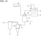
- raw material powder is supplied from a raw material feeder (feeder) A and carried into a burner B with carrier gas supplied from a carrier gas supply device A'.
- Oxygen from an oxygen supply facility C and a fuel gas (liquefied petroleum gas: LPG) from the LPG supply facility D are supplied into the burner B.
- an exhaust gas containing particles spheroidized in the flame in a vertical furnace E is cooled (temperature diluted) by air introduced from a passage F to the bottom of the vertical furnace E, and the spheroidized particles are collected by a cyclone G and a bag filter H in the subsequent stage.
- an oxygen combustion burner using a fuel gas and pure oxygen (hereinafter, may be simply referred to as "oxygen burner”) is usually used.
- Patent Document 1 discloses a diffusion type burner having a concentric double pipe structure in which a large number of small pipes are provided between the inner pipe and the outer pipe.
- Patent Documents 2 and 3 disclose a diffusion type oxygen burner having a concentric quadruple pipe structure. Specifically, the diffusion type burner disclosed in Patent Documents 2 and 3 supplies raw material powder into a combustion chamber using oxygen gas or an oxygen-enriched gas as carrier gas from the center, a fuel gas from the outer periphery thereof, and primary and secondary oxygen from the outer periphery thereof. A cooling-water passage for cooling the burner is provided on the outermost periphery.
- the conventional oxygen burner disclosed in the Patent Documents 1 to 3 generally uses a fuel gas containing a carbon source such as city gas or LPG, a large amount of carbon dioxide, which is a warming gas, is generated at the time of combustion.
- soot which is solid carbon
- the present invention has been made in view of the above circumstances, and an object of the present invention is to provide an apparatus for producing inorganic spheroidized particles and a method for producing inorganic spheroidized particles which can significantly reduce the amount of warming gas generated and suppress the generation of soot during combustion.
- the present invention has adopted the following configuration.
- the apparatus for producing inorganic spheroidized particles of the present invention uses ammonia containing no carbon source as a fuel gas, the amount of warming gas generated can be significantly reduced and the generation of soot during combustion can be suppressed.
- the method for producing inorganic spheroidized particles of the present invention can significantly reduce the amount of warming gas generated and suppress the generation of soot during combustion.
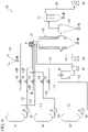
- FIG. 1 is a system diagram showing an example of an apparatus for producing inorganic spheroidized particles of the first embodiment according to the present invention.
- the apparatus 10 for producing inorganic spheroidized particles (hereinafter, may be simply referred to as "apparatus") of the present embodiment includes a burner 11 for producing inorganic spheroidized particles, an ammonia supply source 12, an oxygen supply source 13, a raw material powder supply source 14, a spheroidizing furnace 15, a cyclone 16, a bag filter 17, an ammonia supply line L1, an oxygen supply line L2, and a cooling-water circulation line L3.
- FIGS.2 to 4 show a burner for producing inorganic spheroidized particles (hereinafter, may be simply referred to as a burner) applicable to the apparatus 10 of the present embodiment.
- FIG. 2 shows a plan view of the burner from the tip side thereof
- FIG. 3 a cross-sectional view taken along the line A-A' shown in FIG.2
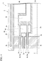
- FIG. 4 is an enlarged cross-sectional view of the tip end side of the burner.
- the burner 11 has a concentric multi-pipe structure including a raw material powder supply pipe 2, a first fuel supply pipe 3, and a first combustion-supporting gas supply pipe 4, and a water-cooling jacket 5 from the central axis C of the burner 11 toward the outside in the circumferential direction. Further, the burner 11 is an oxygen combustion burner using a fuel gas and a combustion-supporting gas containing oxygen.
- the raw material powder supply pipe 2 extends along the axial direction of the burner 11 at the innermost portion of the concentric multi-pipe structure of the burner 11.
- the space inside the raw material powder supply pipe 2 is a raw material powder supply path 2A.
- the raw material powder supply path 2A branches into a plurality of raw material powder supply branched flow paths 2B extending radially from the central axis of the burner 1 at a portion near the tip in the axial direction of the burner 11.
- the raw material powder supply branched flow paths 2B communicate with raw material powder ejection holes 2a having an opening at the tip in the axial direction of the burner.
- the burner 11 ejects the raw material powder in the direction parallel to the central axis C of the burner 11 through the raw material powder supply path 2A, a plurality of the raw material powder supply branched flow paths 2B, and a plurality of the raw material powder ejection holes 2a.
- the openings of a plurality of the raw material powder ejection holes 2a are arranged annularly at equal intervals so as to be centered on the central axis of the burner 1.
- the heat generated by the flame formed inside or outside the raw material powder supply holes 2a can be efficiently received by the raw material powder.
- the raw material powder supply path 2A is provided with a dispersion plate 2b for uniformly dispersing the raw material powder into a plurality of the raw material powder supply branched flow paths 2B in the portion near the tip of the burner 11 in the axial direction.
- raw material powder supply path 2A is connected to the raw material powder supply source 14 on the proximal end side through an oxygen gas supply line L2B described later.
- the carrier gas is not particularly limited as long as it is a gas capable of carrying the raw material powder.
- an inert gas such as nitrogen gas or argon gas can be used as the carrier gas.
- oxygen or oxygen-enriched air when used as the carrier gas, the carrier gas can be also used as a combustion-supporting agent for the raw material powder. As a result, when forming a flame described later, a higher-temperature flame can be formed.
- the first fuel supply pipe 3 is provided so as to cover the outside of the raw material powder supply pipe 2.
- the central axis of the first fuel supply pipe 3 and the central axis of the raw material powder supply pipe 2 coincide with each other, and the first fuel supply pipe 3 is provided coaxially with the raw material powder supply pipe 2.
- the first fuel gas supply path 3A for supplying the first fuel gas.
- the first fuel gas supply path 3A is provided so as to cover the outer periphery of the first powder supply path 2A.
- the base end side of the first fuel gas supply path 3A is connected to the ammonia supply source 12, which is the first fuel gas, through the ammonia supply line L1 .
- Ammonia (NH3) is used as the first fuel gas.
- the first fuel gas may be diluted with an inert gas such as nitrogen gas or argon gas.
- the tip of the first fuel gas supply path 3A is on the base end side in the axial direction of the burner 11 with respect to the position at which the raw material powder supply path 2A branches into a plurality of the raw material powder supply branched flow paths 2B. Therefore, the first fuel gas supply path 3A is not provided on the outer periphery of the portion near the tip of the first powder supply path 2A.
- the annular space near the tip of the first fuel gas supply path 3A has a larger outer diameter than that of the base end portion and the central portion.
- the outer periphery of the annular space near the tip of the first fuel gas supply path 3A is preferably located outside the raw material powder ejection holes 2a.
- the tip of the first fuel gas supply path 3A of which the diameter is expanded in the radial direction from the central axis C of the burner 11 is connected to a plurality of first fuel gas ejection nozzles (first fuel supply support flow paths) 3a extending in a direction parallel to the axial direction of the burner 11.
- the first fuel gas supply path 3A and the space inside a plurality of the first fuel gas ejection nozzles 3a are communicated with each other.
- the fuel gas can be supplied from the first fuel gas supply path 3A into a plurality of the first fuel gas ejection nozzles 3a.
- the first fuel gas supply path 3A branches into a plurality of the first fuel gas ejection nozzles 3a at the portion near the tip of the burner 11.
- the first combustion-supporting gas supply pipe 4 is provided so as to cover the outside of the first fuel supply pipe 3.
- the central axis of the first combustion-supporting gas supply pipe 4 coincides with the central axis of the first fuel supply pipe 3, and the first combustion-supporting gas supply pipe 4 is provided coaxially with the first fuel supply pipe 3 and the raw material powder supply pipe 2.
- the annular space provided between the first combustion-supporting gas supply pipe 4 and the first fuel supply pipe 3 is the first combustion-supporting gas supply path 4A for supplying the first combustion-supporting gas.
- the first combustion-supporting gas supply path 4A is provided so as to cover the tip and the outer periphery of the first fuel gas supply path 3A.
- the base end side of the first combustion-supporting gas supply path 4A is connected to the oxygen supply source 13, which is the first combustion-supporting gas, through the oxygen supply lines L2 and L2A.
- the first combustion-supporting gas is not particularly limited as long as it is a gas capable of reacting with the first fuel gas to form a flame atmosphere.
- Examples of the first combustion-supporting gas include oxygen, and oxygen-enriched air.
- the tip of the first combustion-supporting gas supply path 4A is on the tip side in the axial direction of the burner 11 with respect to the position at which the raw material powder supply path 2A branches into a plurality of the raw material powder supply particulate flow paths 2B. Therefore, the first combustion-supporting gas supply path 4A is provided so as to cover the outer periphery of the portion near the tip of the first powder supply path 2A.
- the annular space near the tip of the first combustion-supporting gas supply path 4A has a smaller inner diameter than that of the base end portion and the central portion.
- the inner periphery of the annular space near the tip of the first combustion-supporting gas supply path 4A is preferably located inside the raw material powder ejection holes 2a.
- the tip of the first combustion-supporting gas supply path 4A of which the diameter is expanded from the outside in the circumferential direction toward the central axis C of the burner 11 is connected to a plurality of first combustion-supporting gas supply holes (first combustion-supporting gas supply branched flow path) 4a which extend in a direction parallel to the axial direction of the burner 11.
- the first combustion-supporting gas supply path 4A and the space inside a plurality of the first combustion-supporting gas supply holes 4a are communicated with each other.
- the first combustion-supporting gas can be supplied from the first combustion-supporting gas supply path 4A to a plurality of the first combustion-supporting gas supply holes 4a.
- the first combustion-supporting gas supply path 4A branches into a plurality of the first combustion-supporting gas supply holes 4a at the portion near the tip of the burner 11.
- the water-cooling jacket 5 is provided so as to cover the outside of the first combustion-supporting gas supply pipe 4.
- the water-cooling jacket 5 is provided with a cooling-water inlet 5A and a cooling-water outlet 5B.
- the cooling-water supplied from the cooling-water inlet 5A into the flow path in the water-cooling jacket 5 is discharged from the cooling-water outlet 5B after cooling the burner 1 particularly near the tip of the burner 11.
- the first fuel gas ejection nozzle 3a is located inside the first combustion-supporting gas supply hole 4a. Further, a tip 3b of the first fuel gas ejection nozzle 3a is located inside the first combustion-supporting gas supply hole 4a. That is, the first fuel gas ejection nozzle 3a opens inside the first combustion-supporting gas supply hole 4a.
- the combustion-supporting gas is supplied from the first combustion-supporting gas supply path 4A toward the inside of the first combustion-supporting gas supply hole 4a. Then, the first fuel gas and the first combustion-supporting gas are mixed inside the first combustion-supporting gas supply hole 4a in front of the tip 3b of the first fuel gas ejection nozzle 3a.
- the space from the tip 3b of the first fuel gas ejection nozzle 3a to a tip 4b of the first combustion-supporting gas supply hole 4a is a first premixing chamber 6 for mixing the first fuel gas and the first combustion-supporting gas. Further, the opening at the tip 4b of the first combustion-supporting gas supply hole 4a becomes an opening 6a of the first premixing chamber 6.
- the burner 11 includes a plurality of the first premixing chambers 6. These first premixing chambers 6 are located at a position near to the tip of the burner 11 in the axial direction.
- the first premixing chamber 6 communicates with one of the first fuel gas ejection nozzles 3a and one of the combustion-supporting gas supply holes 4a.
- the first premixing chamber 6 opens at the tip of the burner 1 in the axial direction.
- a volume v1 of the first premixing chamber 6 is not particularly limited as long as the first fuel gas and the first combustion-supporting gas can be sufficiently mixed and there is no risk of flashback.
- the volume v1 [m 3 ] is preferably in a range from 3.0 ⁇ 10 -5 to 1.0 ⁇ 10 -3 [m 3 ], and more preferably in a range from 1.0 ⁇ 10 -4 to 1.0 ⁇ 10 -3 [m 3 ].
- the volume v1 is in the range from 1.0 ⁇ 10 -4 to 1.0 ⁇ 10 -3 [m 3 ]
- the first fuel gas and the first combustion-supporting gas can be sufficiently mixed.
- the offset distance L1 from the tip 3b of the first fuel gas ejection nozzle 3a to the tip 4b of the first combustion-supporting gas supply hole 4a is preferably in a range from 1.0 ⁇ 10 -3 to 1.0 ⁇ 10 -1 [m], and more preferably in a range from 2 ⁇ 10 -3 to 5 ⁇ 10 -2 [m].
- the number and volume of the first premixing chamber 6 can be appropriately selected according to the supply amount of the mixed gas of the first fuel gas and the first combustion-supporting gas, the number, the volume, and the layout (arrangement) of the raw material powder ejection hole 2a.
- the first fuel gas and the first combustion-supporting gas are mixed in advance and ejected as a mixed gas from the opening 6a in a direction parallel to the axial direction of the burner 1.
- the burner 11 uses ammonia containing no carbon source as the first fuel gas
- the burner 11 includes a plurality of the first premixing chambers 6 having a small volume, and the first fuel gas and the first combustion-supporting gas are premixed in these first premixing chambers 6.
- the first fuel gas and the first combustion-supporting gas can be sufficiently mixed to improve the combustion efficiency, and there is no risk of flashback.
- the openings 6a of the plurality of the first premixing chambers 6 are arranged at equal intervals on the inside and outside of the raw material powder ejection holes 2a arranged in an annular shape centered on the central axis C of the burner 11 so as to be concentric circles. That is, the raw material powder ejection holes 2a are surrounded inside and outside by the openings 6a of the first premixing chambers 6.
- first flame a flame
- the openings 6a of a plurality of the first premixing chambers 6 are arranged in an annular shape, and a plurality of the raw material powder ejection holes 2a are arranged in an annular shape so as to surround the outer periphery of the first flame in the burner 11.
- the openings 6a of a plurality of the first premixing chambers 6 are arranged in an annular shape.
- the entrained air from the periphery of the burner 11 or the combustion exhaust gas in the furnace can be blocked, so that the efficiency of melting and spheroidizing of the inorganic powder can be improved.
- the ammonia supply source 12 is a facility for storing ammonia used as the fuel gas. Ammonia is usually stored as a liquefied gas.
- the ammonia supply line L1 is located between the ammonia supply source 12 and the burner 11. Specifically, the ammonia supply line L1 communicates with the base end side of the first fuel gas supply path 3A of the burner 11. In other words, the ammonia supply source 12 and the first fuel gas supply path 3A are connected through the ammonia supply line L1. As a result, the ammonia gas can be supplied to the burner 11 as the first fuel gas from the ammonia supply source 12.
- the ammonia supply line L1 is provided with a heat exchanger H2, which will be described later, and a flow rate adjusting valve V1. Further, the ammonia supply line L1 may be provided with a vaporizer (not shown) for vaporizing liquid ammonia.
- the oxygen supply source 13 is a facility for storing oxygen used as the combustion-supporting gas or the carrier gas.
- the method for storing oxygen is not particularly limited, but it is preferable to store it as liquefied oxygen as a mode in which a large capacity can be stored.
- the oxygen supply line L2 is located between the oxygen supply source 13 and the burner 11.
- the oxygen supply line L2 branches into L2A and L2B at the Q1 point.
- the oxygen supply line L2 is provided with a heat exchanger H1 which will be described later. Further, the oxygen supply line L2 may be provided with a vaporizer (not shown) for vaporizing liquid oxygen.
- the branched oxygen supply lines L2A and L2B are provided with flow rate control valves V2 and V3, respectively.
- the branched oxygen supply line L2A communicates with the base end side of the first combustion-supporting gas supply path 4A of the burner 11.
- the oxygen supply source 13 and the first combustion-supporting gas supply path 4A are connected through the oxygen supply lines L2 and L2A.
- oxygen gas can be supplied to the burner 11 as the first combustion-supporting gas from the oxygen supply source 13.
- the branched oxygen supply line L2B communicates with the base end side of the raw material powder supply path 2A of the burner 11.
- the oxygen supply source 13 and the raw material powder supply path 2A are connected through oxygen supply lines L2 and L2B.
- oxygen gas can be supplied to the burner 11 as the carrier gas.
- the raw material powder supply source 14 is a facility for storing the raw material powder, and is provided in the branched oxygen supply line L2B.
- the raw material powder supply source 14 and the raw material powder supply path 2A are connected through the oxygen supply line L2B.
- the inorganic powder which is the raw material powder, can be supplied to the burner 11 together with the carrier gas (oxygen gas).
- the form of the raw material powder supply source 14 is not particularly limited.
- the raw material powder supply source 14 may have a raw material tank, a raw material-cutting mechanism, and the like.
- the raw material powder is not particularly limited as long as it is a compound (inorganic powder) for which spherical particles are desired to be obtained.
- a compound inorganic powder
- specific examples of such a compound include inorganic oxides such as SiO 2 , Al 2 O 3 , MgO and Fe 2 O 3 .
- the particle morphology of the raw material powder is not particularly limited, and may be non-spherical particles having corners or spherical particles having no corners.
- the particle size of the raw material powder is preferably in the range from 1 to 500 ⁇ m, and preferably in the range from 1 to 100 ⁇ m.
- the particle size of the raw material powder is less than 1 ⁇ m, the particles aggregate due to static electricity, and if it exceeds 500 ⁇ m, it cannot be sufficiently heated in a burner flame, which is not preferable.
- it is within the range above it is preferable because the raw material powder can be sufficiently heated and spheroidized while being appropriately dispersed in the flame.
- the cooling-water circulation line L3 is located between the cooling-water outlet 5B and the cooling-water inlet 5A of the water-cooling jacket 5 in the burner 11.
- the cooling-water circulation line L3 is provided with a cooling tower CT for storing cooling-water, a pump P1, a heat exchanger H1 and the heat exchanger H2.
- the cooling-water in the cooling tower CT is supplied from the cooling-water inlet 5A into the water-cooling jacket 5 by the pump P1 and discharged from the cooling-water outlet 5B after the cooling of the burner 11 is completed.
- high-temperature cooling-water discharged from the water-cooling jacket 5 is cooled by heat exchange with low-temperature liquefied oxygen or oxygen gas in the heat exchanger H1 provided over the cooling-water circulation line L3 and the oxygen supply line L2.
- the cooling-water is cooled by heat exchange with low-temperature liquefied ammonia or ammonia gas in the heat exchanger H2 provided over the cooling-water circulation line L3 and the ammonia supply line L1, and then supplied into the cooling tower CT.
- the cooling-water used for the water-cooling jacket 5 of the burner 11 can be used as a heat source for vaporizing or heating liquefied oxygen or liquefied ammonia.
- the spheroidizing furnace 15 is a cylindrical vertical furnace, and the burner 11 is attached to the ceiling portion (furnace top portion) vertically downward so that the tip end side thereof faces the inside of the furnace.
- An air introduction line L4 provided with a blower P2 is connected near the bottom of the spheroidizing furnace 15, from which cooling air can be introduced inside of the spheroidizing furnace 15 to lower the temperature of the discharged combustion gas.
- a combustion gas discharge line L5 provided with an exhaust blower P3 is connected to the vicinity of the bottom of the spheroidizing furnace 15. As a result, the generated spheroidized particles are carried by the combustion gas and sent to the inlet of the cyclone 16.
- a duct is provided at the outlet of the cyclone 16, and the duct is connected to the inlet of the bag filter 17.
- the inorganic powder is melted and spheroidized by the burner flame formed by the combustion of the fuel gas containing ammonia and the combustion-supporting gas containing oxygen.
- the raw material powder supplied from the raw material powder supply source 14 is supplied into the raw material powder supply path 2A of the burner 11 using the carrier gas (oxygen gas) supplied from the oxygen supply source 13 through the oxygen supply lines L2 and L2B, and ejected from a plurality of the raw material powder ejection holes 2a toward the spheroidizing furnace 15.
- the carrier gas oxygen gas
- a predetermined amount of ammonia gas (first fuel gas) is sent from the ammonia supply source 12 into the first fuel gas supply path 3A of the burner 11 through the ammonia supply line L1
- a predetermined amount of oxygen gas (first combustion-supporting gas) is sent from the oxygen supply source 13 into the first combustion-supporting gas supply path 4A of the burner 11 through the oxygen supply lines L2 and L2A.
- a mixed gas of ammonia gas (first fuel gas) and oxygen gas (first combustion-supporting gas) is ejected toward the spheroidizing furnace 15 from the openings 6a of a plurality of the first premixing chambers 6 of the burner 11.
- the raw material powder is surrounded by the first flame and the second flame formed by the combustion of the mixed gas ejected from the openings 6a of the first premixing chambers 6.
- the inorganic powder which is the raw material powder, is melted and spheroidized.
- the spheroidized particles are suspended in a mixed gas of the combustion gas generated from the burner 11 and the air introduced from the air introduction line L4, and sent into the cyclone 16 through the combustion gas discharge line L5 provided at the spheroidizing furnace 15.
- the temperature of the gas introduced into the cyclone 16 is lowered, and the temperature becomes suitable for collecting particles in the cyclone 16.
- cyclone 16 coarse spheroidized particles are collected from the spheroidized particles suspended in the gas.
- the gas derived from the cyclone 16 is sent to the bag filter 17, and fine spheroidized particles are collected from among the spheroidized particles.
- ammonia gas containing no carbon source is used as the first fuel gas.
- the first fuel gas and the first combustion-supporting gas are supplied into a plurality of the first premixing chambers 6 of the burner 11 and mixed in advance to form a flame. Then, the inorganic powder is put into the flame. In this way, by supplying the first fuel gas and the first combustion-supporting gas into the first premixing chambers 6, the combustion efficiency can be improved even when a substance containing no carbon source is used as the first fuel gas. Further, when the burner 11 is operated to combust, the possibility of flashback can be reduced.
- the burner 11 uses ammonia (NH3) containing no carbon source as the fuel gas, so that it is possible to significantly reduce the amount of warming gas such as carbon dioxide (CO 2 ) generated. In addition, it is possible to suppress the generation of soot caused by the carbon source in the fuel and prevent soot from being contaminated into the product inorganic spheroidized particles.
- NH3 ammonia
- CO 2 carbon dioxide
- the amount of warming gas generated can be significantly reduced and the generation of soot during combustion can be suppressed.
- the cooling-water used for the water-cooling jacket 5 of the burner 11 can be used as a heat source for vaporizing or heating liquefied oxygen or liquefied ammonia. Therefore, since it is not necessary to provide a large vaporizer or heater in the ammonia supply source 12, the ammonia supply passage L1, the oxygen supply source 13, and the oxygen supply line L2, it is possible to reduce the size of the apparatus and save energy.
- FIG. 5 is a system diagram showing an apparatus 20 according to the second embodiment of the present invention.
- the apparatus 20 of the present embodiment has a configuration different from that of the apparatus 10 of the first embodiment in that the apparatus 20 further includes the fuel supply source for auxiliary combustion 18 and the fuel supply line for auxiliary combustion L6. Therefore, regarding the apparatus 20 of the present embodiment, the same components as those of the first embodiment are designated by the same reference numerals, and the description thereof will be omitted.
- the apparatus 20 of the present embodiment (hereinafter, may be simply referred to as "apparatus”) includes a burner 11 for producing inorganic spheroidized particles, the ammonia supply source 12, the oxygen supply source 13, the raw material powder supply source 14, the spheroidizing furnace 15, the cyclone 16, the bag filter 17, the ammonia supply line L1, the oxygen supply line L2, the cooling-water circulation line L3, the fuel supply source for auxiliary combustion 18, and the fuel supply line L6 for auxiliary combustion.
- the fuel supply source for auxiliary combustion 18 is a facility for storing auxiliary fuel used as a part of fuel gas.
- the ammonia gas used as the fuel gas has a lower combustion property than the conventional gaseous fuel containing a carbon source or hydrogen, so that the fuel for auxiliary combustion is supplied into the first fuel gas ejection nozzle 3a of the burner 11. Thereby, the flame temperature of the burner can be maintained high while reducing the carbon dioxide generated at the time of combustion, so that the raw material powder can be efficiently melted.
- a gaseous fuel such as methane (CH 4 ) or propane (C 3 H 8 ) can be used.
- a liquid fuel such as kerosene or alcohol can also be used.
- the fuel supply line for auxiliary combustion L6 is connected to the ammonia supply line L1 at the position Q2 of the ammonia supply line L1 near the burner 11.
- the fuel supply line for auxiliary combustion L6 is located between the fuel supply source for auxiliary combustion 18 and the burner 11, and is connected to the base end side of the first fuel gas supply path 3A of the burner 11 through the ammonia supply line L1.
- the fuel supply source for auxiliary combustion 18 and the first fuel gas supply path 3A are connected through the fuel supply line for auxiliary combustion L6 and the ammonia supply line L1.
- the fuel for auxiliary combustion can be supplied to the burner 11 as a part of the first fuel gas from the fuel supply source for auxiliary combustion 18.
- the fuel supply line for auxiliary combustion L6 is provided with a heat exchanger H3 and a flow rate control valve V4. Thereby, the temperature and the supply amount of the fuel for auxiliary combustion supplied to the burner 11 can be appropriately adjusted.
- the inorganic powder is melted by the burner flame formed by combustion of the fuel gas containing ammonia and the fuel for auxiliary combustion, and the combustion-supporting gas containing oxygen, and the inorganic powder is spherical.
- the fuel supply source for auxiliary combustion 18 and the fuel supply line for auxiliary combustion L6 are used, and the fuel for auxiliary combustion is supplied to the first fuel gas ejection nozzle 3a when the burner 11 is ignited.
- the flame temperature of the burner can be maintained high while reducing the carbon dioxide generated during combustion, and the raw material powder can be efficiently melted.
- the fuel for auxiliary combustion may be used only at the time of ignition, and the supply of the fuel for auxiliary combustion may be stopped after the combustion of the burner 11 is stabilized, or the supply may be continued while adjusting the flow rate by the flow rate control valve V4.
- the same effects as those of the first embodiment can be obtained, and the combustion state of the burner 11 can be easily stabilized.
- FIG. 6 is a system diagram showing an apparatus 30 according to the third embodiment of the present invention.
- the apparatus 30 of the present embodiment has a different configuration from that of the apparatus 20 of the second embodiment in that the configuration of the burner and the connection position of each supply line to the burner are different. Therefore, regarding the apparatus 30 of the present embodiment, the same components as those of the first and second embodiments are designated by the same reference numerals, and the description thereof will be omitted.
- FIGS. 7 to 9 show a burner 21 applicable to the apparatus 30 of the third embodiment
- FIG. 7 is a plan view of the burner 21 as viewed from the tip side thereof
- FIG. 8 is a cross-sectional view cut along the line B-B passing through the central axis C of the burner 21,
- FIG. 9 is an enlarged cross-sectional view of the tip end side of the burner 21.
- the burner 21 has a concentric multi-pipe structure including the raw material powder supply pipe 2, a first fuel supply pipe 23, a first combustion-supporting gas supply pipe 24, a second fuel supply pipe 7, a second combustion-supporting gas supply pipe 8, and the water-cooling jacket 5 from the central axis C of the burner 21 toward the outside in the circumferential direction.
- the burner 21 of the present embodiment is an oxygen combustion burner using a fuel gas and a combustion-supporting gas containing oxygen.
- the first fuel supply pipe 23 is provided so as to cover the outside of the raw material powder supply pipe 2.
- the central axis of the first fuel supply pipe 23 and the central axis of the raw material powder supply pipe 2 coincide with each other, and the first fuel supply pipe 23 is provided coaxially with the raw material powder supply pipe 2.
- the annular space provided between the first fuel supply pipe 23 and the raw material powder supply pipe 2 is the first fuel gas supply path 23A for supplying the first fuel gas.
- the first fuel gas supply path 23A is provided so as to cover the outer periphery of the first powder supply path 2A.
- the base end side of the first fuel gas supply path 23A is connected to the fuel supply source for auxiliary combustion 18 through the fuel supply line for auxiliary combustion L6 described above.
- the fuel for auxiliary combustion can be used, but the first fuel gas is not limited to these gases.
- ammonia NH 3
- NH 3 ammonia
- the first fuel gas may be diluted with an inert gas such as nitrogen gas or argon gas.
- the tip of the first fuel gas supply path 23A is on the base end side in the axial direction of the burner 21 with respect to the position at which the raw material powder supply path 2A branches into a plurality of the raw material powder supply branched flow paths 2B. Therefore, the first fuel gas supply path 23A is not provided on the outer periphery of the portion near the tip of the first powder supply path 2A.
- the annular space near the tip of the first fuel gas supply path 23A has the same or slightly larger outer diameter than that of the base end portion and the central portion.
- the outer periphery of the annular space near the tip of the first fuel gas supply path 23A is preferably inside the raw material powder ejection holes 2a.
- a plurality of the first fuel gas ejection nozzles (first fuel supply branch flow paths) 3a extending in a direction parallel to the axial direction of the burner 21 are connected to the tip of the first fuel gas supply path 23A.
- the first fuel gas supply path 23A and the space inside the plurality of the first fuel gas ejection nozzles 3a are communicated with each other.
- the fuel gas can be supplied from the first fuel gas supply path 23A to the plurality of the first fuel gas ejection nozzles 3a.
- the first fuel gas supply path 23A branches into a plurality of the first fuel gas ejection nozzles 3a at a portion near the tip of the burner 21.
- the first combustion-supporting gas supply pipe 24 is provided so as to cover the outside of the first fuel supply pipe 23.
- the central axis of the first combustion-supporting gas supply pipe 24 coincides with the central axis of the first fuel supply pipe 23, and the first combustion-supporting gas supply pipe 24 is provided coaxially with the first fuel supply pipe 23 and the raw material powder supply pipe 2.
- the annular space provided between the first combustion-supporting gas supply pipe 24 and the first fuel supply pipe 23 is the first combustion-supporting gas supply path 24A for supplying the first combustion-supporting gas.
- the first combustion-supporting gas supply path 24A is provided so as to cover the tip and the outer periphery of the first fuel gas supply path 23A.
- the base end side of the first combustion-supporting gas supply path 24A is connected to the oxygen supply source 13 through the oxygen supply lines L2 and L2A.
- the first combustion-supporting gas is not particularly limited as long as it is a gas capable of reacting with the first fuel gas to form a flame atmosphere, as in the first embodiment.
- Examples of the first combustion-supporting gas include oxygen, and oxygen-enriched air.
- the tip of the first combustion-supporting gas supply path 24A is on the tip side in the axial direction of the burner 21 with respect to the position at which the raw material powder supply path 2A branches into a plurality of the raw material powder supply branched flow paths 2B. Therefore, the first combustion-supporting gas supply path 24A is provided so as to cover the outer periphery of the portion near the tip of the first powder supply path 2A.
- the annular space near the tip of the first combustion-supporting gas supply path 24A has a smaller inner diameter than that of the base end portion and the central portion.
- the inner periphery of the annular space near the tip of the first combustion-supporting gas supply path 24A is preferably inside the raw material powder ejection hole 2a.
- the tip of the first combustion-supporting gas supply path 24A of which the diameter is expanded from the outside in the circumferential direction of the burner 21 toward the central axis C is connected to a plurality of the first combustion-supporting gas supply holes (first combustion-supporting gas supply branched flow paths) 4a which extend in a direction parallel to the axial direction of the burner 21.
- the first combustion-supporting gas supply path 24A and the space inside the plurality of the first combustion-supporting gas supply holes 4a are communicated with each other.
- the first combustion-supporting gas can be supplied from the first combustion-supporting gas supply path 24A to a plurality of the first combustion-supporting gas supply holes 4a.
- the first combustion-supporting gas supply path 24A branches into a plurality of the first combustion-supporting gas supply holes 4a at the portion near the tip of the burner 21.
- the second fuel supply pipe 7 is provided so as to cover the outside of the first combustion-supporting gas supply pipe 24.
- the central axis of the first fuel supply pipe 23 coincides with the central axis of the first combustion-supporting gas supply pipe 24, and the second fuel supply pipe 7 is provided coaxially with the first combustion-supporting gas supply pipe 24.
- the annular space provided between the second fuel supply pipe 7 and the first combustion-supporting gas supply pipe 24 is the second fuel gas supply path 7A for supplying the second fuel gas.
- the second fuel gas supply path 7A is provided so as to cover the outer periphery of the first combustion-supporting gas supply path 24A.
- the base end side of the second fuel gas supply path 7A is connected to the ammonia supply source 12 through the ammonia supply line L1.
- ammonia gas is used as the second fuel gas
- a gas containing the fuel for auxiliary combustion may be used as in the case of the first fuel gas.
- the second fuel gas may be diluted with an inert gas such as nitrogen gas or argon gas, if necessary.
- the tip of the second fuel gas supply path 7A is about the same as that of the first fuel gas supply path 23A in the axial direction of the burner 21. Therefore, the second fuel gas supply path 7A is not provided on the outer periphery of the portion near the tip of the first powder supply path 2A.
- the annular space near the tip of the second fuel gas supply path 7A has the same or slightly larger outer diameter than that of the base end portion and the central portion.
- the outer periphery of the annular space near the tip of the second fuel gas supply path 7A is preferably outside the position of the raw material powder ejection holes 2a.
- a plurality of second fuel gas ejection nozzles (second fuel supply branch flow path) 7a extending in a direction parallel to the axial direction of the burner 21 are connected to the tip of the second fuel gas supply paths 7A.
- the second fuel gas supply path 7A and the space inside the plurality of the second fuel gas ejection nozzles 7a are communicated with each other.
- the second fuel gas can be supplied from the second fuel gas supply path 7A to the plurality of the second fuel gas ejection nozzles 7a.
- the second fuel gas supply path 7A branches into a plurality of the second fuel gas ejection nozzles 7a at the portion near the tip of the burner 21.
- the second combustion-supporting gas supply pipe 8 is provided so as to cover the outside of the second fuel supply pipe 7.
- the central axis of the second combustion-supporting gas supply pipe 8 coincides with the central axis of the second fuel supply pipe 7, and the second combustion-supporting gas supply pipe 8 is provided coaxially with the second fuel supply pipe 7 and the raw material powder supply pipe 2.
- the annular space provided between the second combustion-supporting gas supply pipe 8 and the second fuel supply pipe 7 is the second combustion-supporting gas supply path 8A for supplying the second combustion-supporting gas.
- the second combustion-supporting gas supply path 8A is provided so as to cover the tip and the outer periphery of the second fuel gas supply path 7A.
- the base end side of the second combustion-supporting gas supply path 8A is connected to the oxygen supply source 13 through the oxygen supply lines L2 and L2C.
- the second combustion-supporting gas is not particularly limited as long as it is a gas capable of reacting with the second fuel gas to form a flame atmosphere, like the first combustion-supporting gas.
- Examples of the second combustion-supporting gas include oxygen and oxygen-enriched air.
- the second combustion-supporting gas may have the same component as the first combustion-supporting gas, or may have a different component.
- the tip of the second combustion-supporting gas supply path 8A is on the tip side in the axial direction of the burner 21 with respect to the position at which the raw material powder supply path 2A branches into a plurality of the raw material powder supply branched flow paths 2B. Therefore, the second combustion-supporting gas supply path 8A is provided so as to cover the outer periphery of the portion near the tip of the first combustion-supporting gas supply path 24.
- the annular space near the tip of the second combustion-supporting gas supply path 8A has a smaller inner diameter than that of the base end portion and the central portion.
- the inner periphery of the annular space near the tip of the second combustion-supporting gas supply path 8A is preferably outside the position of the raw material powder ejection hole 2a.
- the tip of the second combustion-supporting gas supply path 8A of which the diameter is expanded from the outside in the circumferential direction of the burner 21 toward the central axis C is connected to a plurality of the second combustion-supporting gas supply holes (second combustion-supporting gas supply branched flow paths) 8a extending in a direction parallel to the axial direction of the burner 21.
- the second combustion-supporting gas supply path 8A and the space inside a plurality of the second combustion-supporting gas supply holes 8a are communicated with each other.
- the second combustion-supporting gas can be supplied from the second combustion-supporting gas supply path 8A to a plurality of the second combustion-supporting gas supply holes 8a.
- the second combustion-supporting gas supply path 8A branches into a plurality of the second combustion-supporting gas supply holes 8a at the portion near the tip of the burner 21.
- the second fuel gas ejection nozzle 7a is located inside the second combustion-supporting gas supply hole 8a. Further, a tip 7b of the second fuel gas ejection nozzle 7a is located inside the second combustion-supporting gas supply hole 8a. That is, the second fuel gas ejection nozzle 7a opens inside the second combustion-supporting gas supply hole 8a.
- the second combustion-supporting gas is supplied from the second combustion-supporting gas supply path 8A toward the inside of the second combustion-supporting gas supply hole 8a. Then, the second fuel gas and the second combustion-supporting gas are mixed inside the second combustion-supporting gas supply hole 8a in front of the tip 7b of the second fuel gas ejection nozzle 7a.
- the space from the tip 7b of the second fuel gas ejection nozzle 7a to a tip 8b of the second combustion-supporting gas supply hole 8a is a second premixing chamber 9 for mixing the second fuel gas and the second combustion-supporting gas. Further, the opening of the tip 8b of the second combustion-supporting gas supply hole 8a becomes the opening 9a of the second premixing chamber 9.
- the burner 21 of the present embodiment includes a plurality of the second premixing chambers 9. These second premixing chambers 9 are located at a position near to the tip of the burner 21 in the axial direction.
- the second premixing chamber 9 communicates with one of the second fuel gas ejection nozzles 7a and one of the second combustion-supporting gas supply holes 8a.
- the second premixing chamber 9 opens at the tip of the burner 21 in the axial direction.
- a volume v2 of the second premixing chamber 9 is not particularly limited as long as the second fuel gas and the second combustion-supporting gas can be sufficiently mixed and there is no risk of flashback.
- the volume v2 [m 3 ] can be the same as the volume v1 of the first premixing chamber 6 described above. That is, when the total flow rate Q1 of the second fuel gas and the second combustion-supporting gas is 25 to 50 [Nm 3 /h], the volume v2 [m 3 ] is preferably in a range from 3.0 ⁇ 10 -5 to 1.0 ⁇ 10 -3 [m 3 ], and more preferably in a range from 1.0 ⁇ 10 -4 to 1.0 ⁇ 10 -3 [m 3 ]. When the volume v2 is in the range from 1.0 ⁇ 10 -4 to 1.0 ⁇ 10 -3 [m 3 ], the second fuel gas and the second combustion-supporting gas can be sufficiently mixed in the second premixing chamber 9.
- an offset distance L2 from the tip 7b of the second fuel gas ejection nozzle 7a to the tip 8b of the second combustion-supporting gas supply hole 8a is preferably in a range from 1.0 ⁇ 10 -3 to 1.0 ⁇ 10 -1 [m], and more preferably in a range from 2 ⁇ 10 -3 to 5 ⁇ 10 -2 [m] as in the offset distance L1 described above.
- the number and the volume of the second premixing chamber 9 can be appropriately selected according to the supply amount of the mixed gas of the second fuel gas and the second combustion-supporting gas, the number and the volume and the layout (arrangement) of the raw material powder ejection hole 2a.
- the second fuel gas and the second combustion-supporting gas are mixed in advance and ejected as a mixed gas from the opening 9a in a direction parallel to the axial direction of the burner 21.
- the burner 21 includes a plurality of the first premixing chambers 6 having a small volume and the second premixing chambers 9 having a small volume, the first fuel gas and the first combustion-supporting gas are premixed in the first premixing chamber 6, and the second fuel gas and the second combustion-supporting gas are mixed in the second premixing chamber 9.
- the fuel gas and the combustion-supporting gas can be sufficiently mixed to improve the combustion efficiency, and there is no risk of flashback.
- a plurality of the openings 6a of the first premixing chamber 6 are arranged at equal intervals inside the raw material powder ejection holes 2a arranged in an annular shape centered on the central axis C of the burner 21 so as to be concentric circles
- a plurality of the openings 9a of the second premixing chamber 9 are arranged at equal intervals outside the raw material powder ejection holes 2a so as to be concentric circles. That is, the raw material powder ejection holes 2a are surrounded inside by the openings 6a of the first premixing chambers 6 and outside by the openings 9a of the second premixing chambers 9.
- the openings 6a of a plurality of the first premixing chambers 6 are arranged in an annular shape, and a plurality of the raw material powder ejection holes 2a are arranged in an annular shape so as to surround the outer periphery of the first flame.
- the openings 9a of a plurality of the second premixing chambers 9 are arranged in an annular shape.
- the entrained air from the periphery of the burner 21 or the combustion exhaust gas in the furnace can be blocked, so that the efficiency of melting and spheroidizing of the inorganic powder can be improved.
- the flow rate of the first fuel gas for forming the first flame and the flow rate of the second fuel gas for forming the second flame are independently controlled, and the flow rate of the first combustion-supporting gas for forming the first flame and the flow rate of the second combustion-supporting gas for forming the second flame can be controlled independently. This makes it possible to create an appropriate combustion state for the raw material powder ejected from the tip of the burner 21.
- the ammonia supply line L1 is located between the ammonia supply source 12 and the burner 21. Specifically, the ammonia supply line L1 communicates with the base end side of the second fuel gas supply path 7A of the burner 21. In other words, the ammonia supply source 12 and the second fuel gas supply path 7A are connected through the ammonia supply line L1. As a result, the ammonia gas can be supplied to the burner 21 as the second fuel gas from the ammonia supply source 12.
- the oxygen supply line L2 is located between the oxygen supply source 13 and the burner 21.
- oxygen supply line L2 branches into L2A, L2B and L2C at the Q1 point.
- the oxygen supply line L2 is provided with a heat exchanger H1 described later. Further, the oxygen supply line L2 may be provided with a vaporizer (not shown) for vaporizing liquid oxygen.
- the branched oxygen supply line L2C is provided with a flow rate-adjusting valve V5.
- the branched oxygen supply line L2A communicates with the base end side of the first combustion-supporting gas supply path 24A of the burner 21.
- the oxygen supply source 13 and the first combustion-supporting gas supply path 24A are connected through the oxygen supply lines L2 and L2A.
- oxygen gas can be supplied to the burner 21 as the first combustion-supporting gas from the oxygen supply source 13.
- the branched oxygen supply line L2B communicates with the base end side of the raw material powder supply path 2A of the burner 21.
- the oxygen supply source 13 and the raw material powder supply path 2A are connected through the oxygen supply lines L2 and L2B.
- oxygen gas can be supplied to the burner 21 as the carrier gas.
- the branched oxygen supply line L2C communicates with the base end side of the second combustion-supporting gas supply path 8A of the burner 21.
- the oxygen supply source 13 and the second combustion-supporting gas supply path 8A are connected through the oxygen supply lines L2 and L2C.
- oxygen gas can be supplied to the burner 21 as a second combustion-supporting gas from the oxygen supply source 13.
- the raw material powder supply source 14 is a facility for storing the raw material powder, and is provided in the branched oxygen supply line L2B.
- the raw material powder supply source 14 and the raw material powder supply path 2A are connected through the oxygen supply line L2B.
- the inorganic powder which is the raw material powder, can be supplied to the burner 11 together with the carrier gas (oxygen gas).
- the form of the raw material powder supply source 14 is not particularly limited.
- the raw material powder supply source 14 may have a raw material tank, a raw material-cutting mechanism, and the like.
- the cooling-water circulation line L3 is located between the cooling-water outlet 5B and the cooling-water inlet 5A of the water-cooling jacket 5 in the burner 21.
- the cooling-water circulation line L3 is provided with the cooling tower CT for storing cooling-water, the pump P1, the heat exchanger H1, the heat exchanger H3, and the heat exchanger H2.
- the cooling-water in the cooling tower CT is supplied from the inlet 5A into the water-cooling jacket 5 by the pump P1 and discharged from the outlet 5B after the cooling of the burner 11 is completed.
- high-temperature cooling-water discharged from the water-cooling jacket 5 is cooled by heat exchange with low-temperature liquefied oxygen or oxygen gas in the heat exchanger H1 provided over the cooling-water circulation line L3 and the oxygen supply line L2.
- the cooling-water is then cooled by heat exchange with the low-temperature fuel for auxiliary combustion in the heat exchanger H3 provided over the cooling-water circulation line L3 and the fuel supply line for auxiliary combustion L6.
- cooling-water is cooled by heat exchange with low-temperature liquefied ammonia or ammonia gas in the heat exchanger H2 provided over the cooling-water circulation line L3 and the ammonia supply line L1, and then supplied into the cooling tower CT.
- the fuel supply line for auxiliary combustion L6 is located between the fuel supply source for auxiliary combustion 18 and the burner 21. Specifically, the fuel supply line for auxiliary combustion L6 communicates with the base end side of the first fuel gas supply path 23A of the burner 21. In other words, the fuel supply source for auxiliary combustion 18 and the first fuel gas supply path 23A are connected through the fuel supply line for auxiliary combustion L6. As a result, the fuel for auxiliary combustion can be supplied to the burner 21 as the first fuel gas from the fuel supply source for auxiliary combustion 18.
- the inorganic powder is melted and spheroidized by a burner flame formed by the combustion of the fuel gas and the combustion-supporting gas containing oxygen.
- ammonia gas containing no carbon source is used as at least one of the first and second fuel gases.
- the fuel gas and the combustion-supporting gas are supplied into a plurality of the first premixing chambers 6 and a plurality of the second premixing chambers 9 of the burner 21, and the fuel gas and the combustion-supporting gas are mixed in advance and then combusted to generate a flame.
- the inorganic powder is put into the flame.
- the supply of the fuel gas and that of the combustion-supporting gas to the first and second fuel gas ejection nozzles of the burner 21 are independent of each other.
- a substance containing a carbon source can be supplied to the first fuel gas ejection nozzle as the fuel for auxiliary combustion, and ammonia (NH 3 ) can be supplied to the second fuel gas ejection nozzle as the fuel gas.
- ammonia has a lower combustion property than conventional gas fuels containing carbon sources and hydrogen. Therefore, when ammonia is used as the fuel gas, the flame temperature of the burner can be maintained high while reducing the carbon dioxide generated during combustion, and the raw material powder can be efficiently melted by supplying the fuel for auxiliary combustion to the first fuel gas ejection nozzle 3a. Further, the fuel for auxiliary combustion may be used only at the time of ignition, and the supply of the fuel for auxiliary combustion may be stopped after the combustion of the burner 21 is stabilized.
- the supply of the fuel gas to the first fuel gas ejection nozzle 3a of the burner 21 and the supply of the fuel gas to the second fuel gas ejection nozzle 7a are independent of each other. It is possible to independently control the flow rates of the first fuel gas and the first combustion-supporting gas for forming the first flame and the flow rates of the second fuel gas and the second combustion-supporting gas for forming the second flame. As a result, even when ammonia gas is used as the fuel gas, it is possible to create an appropriate combustion state for the raw material powder ejected from the tip of the burner 21.
- ammonia supply line L1 and the fuel supply line for auxiliary combustion L6 are merged in the apparatus 20. This configuration may be applied to the third embodiment.
- the mode for supplying the fuel for auxiliary combustion to the burner 11 of the second embodiment and the burner 21 of the third embodiment is not particularly limited.
- first fuel gas supply path 3A or the second fuel gas supply path 7A is connected to the fuel supply source for auxiliary combustion 18, and the fuel for auxiliary combustion can be supplied to the first fuel gas ejection nozzle 3a or the second fuel gas ejection nozzle 7a.
- first premixing chambers 6 or the second premixing chambers 9 to which fuel for auxiliary combustion is supplied it may be possible to change from a mixed combustion of ammonia and fuel for auxiliary combustion to a combustion of 100% ammonia.
- the apparatus 30 for producing inorganic spheroidized particles and the method for producing inorganic spheroidized particles of the third embodiment the embodiment in which a substance containing a carbon source is supplied to the first fuel gas ejection nozzle of the burner 21 as a fuel for auxiliary combustion, and ammonia (NH3) is supplied to the second fuel gas ejection nozzle as the fuel gas has been described.
- ammonia (NH 3 ) may be supplied to the first fuel gas ejection nozzle of the burner 21 as a fuel gas
- a substance containing a carbon source may be supplied to the second fuel gas ejection nozzle as a fuel for auxiliary combustion.
- the present invention can provide a burner for producing inorganic spheroidized particles, an apparatus for producing inorganic spheroidized particles, and a method for producing inorganic spheroidized particles, which can significantly reduce the amount of warming gas generated and suppress the generation of soot during combustion.
Landscapes
- Engineering & Computer Science (AREA)
- Chemical & Material Sciences (AREA)
- Organic Chemistry (AREA)
- Mechanical Engineering (AREA)
- General Engineering & Computer Science (AREA)
- Inorganic Chemistry (AREA)
- Combustion & Propulsion (AREA)
- Life Sciences & Earth Sciences (AREA)
- Geology (AREA)
- Chemical Kinetics & Catalysis (AREA)
- Pre-Mixing And Non-Premixing Gas Burner (AREA)
- Glanulating (AREA)
- Silicon Compounds (AREA)
Abstract
Description
- The present invention relates to an apparatus for producing inorganic spheroidized particles and a method for producing inorganic spheroidized particles.
- Conventionally, a method for producing inorganic spheroidized particles (hereinafter, may be simply referred to as "spheroidized particles") by passing an inorganic powder raw material through a flame is known (
Patent Documents 1 to 3). - For example, in an apparatus for producing inorganic spheroidized particles disclosed in Patent Document 2, as shown in
FIG. 10 , raw material powder is supplied from a raw material feeder (feeder) A and carried into a burner B with carrier gas supplied from a carrier gas supply device A'. Oxygen from an oxygen supply facility C and a fuel gas (liquefied petroleum gas: LPG) from the LPG supply facility D are supplied into the burner B. Then, an exhaust gas containing particles spheroidized in the flame in a vertical furnace E is cooled (temperature diluted) by air introduced from a passage F to the bottom of the vertical furnace E, and the spheroidized particles are collected by a cyclone G and a bag filter H in the subsequent stage. - In order to spheroidize the raw material powder in a flame formed by a burner, a high-temperature flame is required. Therefore, as the burner B shown in
FIG. 10 , an oxygen combustion burner using a fuel gas and pure oxygen (hereinafter, may be simply referred to as "oxygen burner") is usually used. - As such an oxygen burner, for example,
Patent Document 1 discloses a diffusion type burner having a concentric double pipe structure in which a large number of small pipes are provided between the inner pipe and the outer pipe. - Further, Patent Documents 2 and 3 disclose a diffusion type oxygen burner having a concentric quadruple pipe structure. Specifically, the diffusion type burner disclosed in Patent Documents 2 and 3 supplies raw material powder into a combustion chamber using oxygen gas or an oxygen-enriched gas as carrier gas from the center, a fuel gas from the outer periphery thereof, and primary and secondary oxygen from the outer periphery thereof. A cooling-water passage for cooling the burner is provided on the outermost periphery.
- As described above, in the oxygen burner disclosed in
Patent Documents 1 to 3, since the fuel gas and the combustion-supporting gas (oxygen gas) are mixed and combusted in the combustion chamber, a high-temperature oxygen combustion flame can be obtained. -
- Patent Document 1:
Japanese Patent Application, First Publication No. Sho 58-145613 - Patent Document 2:
Japanese Patent No. 3331491 - Patent Document 3:
Japanese Patent No. 3312228 - However, since the conventional oxygen burner disclosed in the
Patent Documents 1 to 3 generally uses a fuel gas containing a carbon source such as city gas or LPG, a large amount of carbon dioxide, which is a warming gas, is generated at the time of combustion. - In addition, when incomplete combustion occurs, soot, which is solid carbon, is generated, so there is a possibility of mixing a small amount of carbon in the product inorganic spheroidized particles.
- The present invention has been made in view of the above circumstances, and an object of the present invention is to provide an apparatus for producing inorganic spheroidized particles and a method for producing inorganic spheroidized particles which can significantly reduce the amount of warming gas generated and suppress the generation of soot during combustion.
- In order to achieve the above problems, the present invention has adopted the following configuration.
- [1] Apparatus for producing inorganic spheroidized particles, including:
- a burner for producing inorganic spheroidized particles which uses a fuel gas containing ammonia and a combustion-supporting gas containing oxygen;
- a vertical spheroidizing furnace in which the burner for producing inorganic spheroidized particles is mounted vertically downward on the top thereof;
- an ammonia supply source;
- an oxygen supply source;
- an ammonia supply line located between the ammonia supply source and the burner for producing inorganic spheroidized particles; and
- an oxygen supply line located between the oxygen supply source and the burner for producing inorganic spheroidized particles.
- [2] The apparatus for producing inorganic spheroidized particles according to [1], wherein the apparatus further includes a fuel supply source for auxiliary combustion, and a fuel supply line for auxiliary combustion located between the fuel supply source for auxiliary combustion and the burner for producing inorganic spheroidized particles.
- [3] The apparatus for producing inorganic spheroidized particles according to [1] or [2], wherein the apparatus further includes a cyclone and a bag filter located downstream of the vertical spheroidizing furnace.
- [4] The apparatus for producing inorganic spheroidized particles according to [1] or [3], wherein the apparatus further includes a fuel supply line for auxiliary combustion located between a fuel supply source for auxiliary combustion and the burner for producing inorganic spheroidized particles, and
the burner for producing inorganic spheroidized particles includes:- a raw material powder supply path which supplies inorganic powder as raw material powder;
- a first fuel gas supply path which supplies a first fuel gas;
- a first combustion-supporting gas supply path which supplies a first combustion-supporting gas;
- the ammonia supply line and the first fuel gas supply path are communicated with each other; and
- the oxygen supply line and the first combustion-supporting gas supply path are communicated with each other.
- [5] The apparatus for producing inorganic spheroidized particles according to [4], wherein the fuel supply line for auxiliary combustion and the first fuel gas supply path are communicated with each other.
- [6] The apparatus for producing inorganic spheroidized particles according to [4] or [5], wherein the burner for producing inorganic spheroidized particles further includes:
- a second fuel gas supply path which supplies a second fuel gas, and
- a second combustion-supporting gas supply path which supplies a second combustion-supporting gas,
- the second fuel gas supply path and one or both of the ammonia supply line and the fuel supply line for auxiliary combustion are communicated with each other, and
- the oxygen supply line and the second combustion-supporting gas supply path are communicated with each other.
- [7] The apparatus for producing inorganic spheroidized particles according to any one of [1] to [6], wherein the burner for producing inorganic spheroidized particles further includes a water-cooling jacket, and a cooling-water circulation line provided between a cooling-water inlet and a cooling-water outlet of the water-cooling jacket.
- [8] The apparatus for producing inorganic spheroidized particles according to [7], wherein the apparatus further includes a heat exchanger provided in the ammonia supply line and the cooling-water circulation line.
- [9] A method for producing inorganic spheroidized particles in which inorganic powder is melted and spheroidized by a burner flame formed by combustion of a fuel gas and a combustion-supporting gas containing oxygen, wherein ammonia is used as the fuel gas.
- Since the apparatus for producing inorganic spheroidized particles of the present invention uses ammonia containing no carbon source as a fuel gas, the amount of warming gas generated can be significantly reduced and the generation of soot during combustion can be suppressed.
- The method for producing inorganic spheroidized particles of the present invention can significantly reduce the amount of warming gas generated and suppress the generation of soot during combustion.
-
- [
FIG. 1] FIG. 1 is a system diagram showing an apparatus for producing inorganic spheroidized particles of the first embodiment according to the present invention. - [
FIG. 2] FIG. 2 is a plan view showing a burner for producing inorganic spheroidized particles applicable to the first embodiment. - [
FIG. 3] FIG. 3 is a cross-sectional view taken along the line A-A' shown inFIG.2 . - [
FIG. 4] FIG. 4 is an enlarged cross-sectional view of the burner shown inFIG. 2 . - [
FIG. 5] FIG. 5 is a system diagram showing an apparatus for producing inorganic spheroidized particles of a second embodiment according to the present invention. - [
FIG. 6] FIG. 6 is a system diagram showing an apparatus for producing inorganic spheroidized particles of a third embodiment according to the present invention. - [
FIG. 7] FIG. 7 is a plan view showing a burner for producing inorganic spheroidized particles applicable to the third embodiment. - [
FIG. 8] FIG. 8 is a cross-sectional view taken along the line B-B' shown inFIG. 7 . - [
FIG. 9] FIG. 9 is an enlarged cross-sectional view of the burner shown inFIG. 8 . - [
Fig. 10] FIG. 10 is a system diagram showing a conventional apparatus for producing inorganic spheroidized particles. - Hereinafter, an apparatus for producing inorganic spheroidized particles of the first embodiment according to the present invention will be described in detail using drawings together with a method for producing inorganic spheroidized particles using the apparatus for producing inorganic spheroidized particles. In addition, in the drawings used in the following explanation, in order to make the features easy to understand, the featured parts may be enlarged for convenience, and the dimensional ratios of each component may not be the same as the actual ones.
- First, the apparatus for producing inorganic spheroidized particles of the first embodiment according to the present invention will be described.
FIG. 1 is a system diagram showing an example of an apparatus for producing inorganic spheroidized particles of the first embodiment according to the present invention. - As shown in
FIG. 1 , theapparatus 10 for producing inorganic spheroidized particles (hereinafter, may be simply referred to as "apparatus") of the present embodiment includes aburner 11 for producing inorganic spheroidized particles, anammonia supply source 12, anoxygen supply source 13, a raw materialpowder supply source 14, aspheroidizing furnace 15, acyclone 16, abag filter 17, an ammonia supply line L1, an oxygen supply line L2, and a cooling-water circulation line L3. - Next, the
burner 11 for producing inorganic spheroidized particles applicable to theapparatus 10 of the present embodiment will be described. -
FIGS.2 to 4 show a burner for producing inorganic spheroidized particles (hereinafter, may be simply referred to as a burner) applicable to theapparatus 10 of the present embodiment.FIG. 2 shows a plan view of the burner from the tip side thereof,FIG. 3 a cross-sectional view taken along the line A-A' shown inFIG.2 , andFIG. 4 is an enlarged cross-sectional view of the tip end side of the burner. - As shown in
FIGS. 2 to 4 , theburner 11 has a concentric multi-pipe structure including a raw material powder supply pipe 2, a first fuel supply pipe 3, and a first combustion-supporting gas supply pipe 4, and a water-coolingjacket 5 from the central axis C of theburner 11 toward the outside in the circumferential direction. Further, theburner 11 is an oxygen combustion burner using a fuel gas and a combustion-supporting gas containing oxygen. - As shown in
FIG. 3 , the raw material powder supply pipe 2 extends along the axial direction of theburner 11 at the innermost portion of the concentric multi-pipe structure of theburner 11. The space inside the raw material powder supply pipe 2 is a raw materialpowder supply path 2A. As a result, it is possible to supply inorganic powder as raw material powder as a mixture with carrier gas. - The raw material
powder supply path 2A branches into a plurality of raw material powder supply branchedflow paths 2B extending radially from the central axis of theburner 1 at a portion near the tip in the axial direction of theburner 11. - Further, as shown in
FIGS. 3 and4 , the raw material powder supply branchedflow paths 2B communicate with raw materialpowder ejection holes 2a having an opening at the tip in the axial direction of the burner. - As a result, the
burner 11 ejects the raw material powder in the direction parallel to the central axis C of theburner 11 through the raw materialpowder supply path 2A, a plurality of the raw material powder supply branchedflow paths 2B, and a plurality of the raw materialpowder ejection holes 2a. - Specifically, as shown in
FIG. 2 , when the tip of theburner 11 is viewed in plan view, the openings of a plurality of the raw materialpowder ejection holes 2a are arranged annularly at equal intervals so as to be centered on the central axis of theburner 1. As a result, the heat generated by the flame formed inside or outside the raw materialpowder supply holes 2a can be efficiently received by the raw material powder. - Further, as shown in
FIGS. 3 and4 , the raw materialpowder supply path 2A is provided with adispersion plate 2b for uniformly dispersing the raw material powder into a plurality of the raw material powder supply branchedflow paths 2B in the portion near the tip of theburner 11 in the axial direction. - Further, the raw material
powder supply path 2A is connected to the raw materialpowder supply source 14 on the proximal end side through an oxygen gas supply line L2B described later. - The carrier gas is not particularly limited as long as it is a gas capable of carrying the raw material powder. Specifically, for example, when safety is taken into consideration, an inert gas such as nitrogen gas or argon gas can be used as the carrier gas. On the other hand, when oxygen or oxygen-enriched air is used as the carrier gas, the carrier gas can be also used as a combustion-supporting agent for the raw material powder. As a result, when forming a flame described later, a higher-temperature flame can be formed.
- As shown in
FIG. 3 , the first fuel supply pipe 3 is provided so as to cover the outside of the raw material powder supply pipe 2. The central axis of the first fuel supply pipe 3 and the central axis of the raw material powder supply pipe 2 coincide with each other, and the first fuel supply pipe 3 is provided coaxially with the raw material powder supply pipe 2. - An annular space provided between the first fuel supply pipe 3 and the raw material powder supply pipe 2 is the first fuel
gas supply path 3A for supplying the first fuel gas. In other words, the first fuelgas supply path 3A is provided so as to cover the outer periphery of the firstpowder supply path 2A. - The base end side of the first fuel
gas supply path 3A is connected to theammonia supply source 12, which is the first fuel gas, through the ammonia supply line L1. - Ammonia (NH3) is used as the first fuel gas. If necessary, the first fuel gas may be diluted with an inert gas such as nitrogen gas or argon gas.
- The tip of the first fuel
gas supply path 3A is on the base end side in the axial direction of theburner 11 with respect to the position at which the raw materialpowder supply path 2A branches into a plurality of the raw material powder supply branchedflow paths 2B. Therefore, the first fuelgas supply path 3A is not provided on the outer periphery of the portion near the tip of the firstpowder supply path 2A. - The annular space near the tip of the first fuel
gas supply path 3A has a larger outer diameter than that of the base end portion and the central portion. The outer periphery of the annular space near the tip of the first fuelgas supply path 3A is preferably located outside the raw materialpowder ejection holes 2a. As a result, as shown inFIG. 2 , when the tip of theburner 11 is viewed in plan view, the first fuel gas for forming a flame can be supplied to a position outside a plurality of the raw materialpowder ejection holes 2a. - As shown in
FIGS. 3 and4 , the tip of the first fuelgas supply path 3A of which the diameter is expanded in the radial direction from the central axis C of theburner 11 is connected to a plurality of first fuel gas ejection nozzles (first fuel supply support flow paths) 3a extending in a direction parallel to the axial direction of theburner 11. The first fuelgas supply path 3A and the space inside a plurality of the first fuelgas ejection nozzles 3a are communicated with each other. As a result, the fuel gas can be supplied from the first fuelgas supply path 3A into a plurality of the first fuelgas ejection nozzles 3a. In other words, the first fuelgas supply path 3A branches into a plurality of the first fuelgas ejection nozzles 3a at the portion near the tip of theburner 11. - As shown in
FIG. 3 , the first combustion-supporting gas supply pipe 4 is provided so as to cover the outside of the first fuel supply pipe 3. The central axis of the first combustion-supporting gas supply pipe 4 coincides with the central axis of the first fuel supply pipe 3, and the first combustion-supporting gas supply pipe 4 is provided coaxially with the first fuel supply pipe 3 and the raw material powder supply pipe 2. - The annular space provided between the first combustion-supporting gas supply pipe 4 and the first fuel supply pipe 3 is the first combustion-supporting
gas supply path 4A for supplying the first combustion-supporting gas. In other words, the first combustion-supportinggas supply path 4A is provided so as to cover the tip and the outer periphery of the first fuelgas supply path 3A. - The base end side of the first combustion-supporting
gas supply path 4A is connected to theoxygen supply source 13, which is the first combustion-supporting gas, through the oxygen supply lines L2 and L2A. - The first combustion-supporting gas is not particularly limited as long as it is a gas capable of reacting with the first fuel gas to form a flame atmosphere. Examples of the first combustion-supporting gas include oxygen, and oxygen-enriched air.
- The tip of the first combustion-supporting
gas supply path 4A is on the tip side in the axial direction of theburner 11 with respect to the position at which the raw materialpowder supply path 2A branches into a plurality of the raw material powder supplyparticulate flow paths 2B. Therefore, the first combustion-supportinggas supply path 4A is provided so as to cover the outer periphery of the portion near the tip of the firstpowder supply path 2A. - The annular space near the tip of the first combustion-supporting
gas supply path 4A has a smaller inner diameter than that of the base end portion and the central portion. The inner periphery of the annular space near the tip of the first combustion-supportinggas supply path 4A is preferably located inside the raw materialpowder ejection holes 2a. As a result, as shown inFIG. 2 , when the tip of theburner 11 is viewed in plan view, the first combustion-supporting gas for forming a flame can be supplied to a position inside a plurality of the raw materialpowder ejection holes 2a. - As shown in
FIGS. 3 and4 , the tip of the first combustion-supportinggas supply path 4A of which the diameter is expanded from the outside in the circumferential direction toward the central axis C of theburner 11 is connected to a plurality of first combustion-supporting gas supply holes (first combustion-supporting gas supply branched flow path) 4a which extend in a direction parallel to the axial direction of theburner 11. The first combustion-supportinggas supply path 4A and the space inside a plurality of the first combustion-supportinggas supply holes 4a are communicated with each other. As a result, the first combustion-supporting gas can be supplied from the first combustion-supportinggas supply path 4A to a plurality of the first combustion-supportinggas supply holes 4a. In other words, the first combustion-supportinggas supply path 4A branches into a plurality of the first combustion-supportinggas supply holes 4a at the portion near the tip of theburner 11. - As shown in
FIG. 3 , the water-coolingjacket 5 is provided so as to cover the outside of the first combustion-supporting gas supply pipe 4. The water-coolingjacket 5 is provided with a cooling-water inlet 5A and a cooling-water outlet 5B. As a result, the cooling-water supplied from the cooling-water inlet 5A into the flow path in the water-coolingjacket 5 is discharged from the cooling-water outlet 5B after cooling theburner 1 particularly near the tip of theburner 11. - In the
burner 11 of the present embodiment, as shown inFIG. 4 , the first fuelgas ejection nozzle 3a is located inside the first combustion-supportinggas supply hole 4a. Further, atip 3b of the first fuelgas ejection nozzle 3a is located inside the first combustion-supportinggas supply hole 4a. That is, the first fuelgas ejection nozzle 3a opens inside the first combustion-supportinggas supply hole 4a. - When the first fuel gas is ejected from the
tip 3b of the first fuelgas ejection nozzle 3a into the inside of the first combustion-supportinggas supply hole 4a, the combustion-supporting gas is supplied from the first combustion-supportinggas supply path 4A toward the inside of the first combustion-supportinggas supply hole 4a. Then, the first fuel gas and the first combustion-supporting gas are mixed inside the first combustion-supportinggas supply hole 4a in front of thetip 3b of the first fuelgas ejection nozzle 3a. - As described above, the space from the
tip 3b of the first fuelgas ejection nozzle 3a to atip 4b of the first combustion-supportinggas supply hole 4a is afirst premixing chamber 6 for mixing the first fuel gas and the first combustion-supporting gas. Further, the opening at thetip 4b of the first combustion-supportinggas supply hole 4a becomes anopening 6a of thefirst premixing chamber 6. - In other words, the
burner 11 includes a plurality of thefirst premixing chambers 6. Thesefirst premixing chambers 6 are located at a position near to the tip of theburner 11 in the axial direction. Thefirst premixing chamber 6 communicates with one of the first fuelgas ejection nozzles 3a and one of the combustion-supportinggas supply holes 4a. Thefirst premixing chamber 6 opens at the tip of theburner 1 in the axial direction. - A volume v1 of the
first premixing chamber 6 is not particularly limited as long as the first fuel gas and the first combustion-supporting gas can be sufficiently mixed and there is no risk of flashback. - For example, when a total flow rate Q1 of the first fuel gas and the first combustion-supporting gas is 25 to 50 [Nm3/h], the volume v1 [m3] is preferably in a range from 3.0 × 10⁻⁵ to 1.0 × 10⁻³ [m3], and more preferably in a range from 1.0 × 10⁻⁴ to 1.0 × 10⁻³ [m3]. When the volume v1 is in the range from 1.0 × 10⁻⁴ to 1.0 × 10⁻³ [m3], the first fuel gas and the first combustion-supporting gas can be sufficiently mixed.
- Further, the offset distance L1 from the
tip 3b of the first fuelgas ejection nozzle 3a to thetip 4b of the first combustion-supportinggas supply hole 4a is preferably in a range from 1.0 × 10⁻³ to 1.0 × 10⁻¹ [m], and more preferably in a range from 2 × 10⁻³ to 5 × 10⁻² [m]. - Further, the number and volume of the
first premixing chamber 6 can be appropriately selected according to the supply amount of the mixed gas of the first fuel gas and the first combustion-supporting gas, the number, the volume, and the layout (arrangement) of the raw materialpowder ejection hole 2a. - In the
first premixing chamber 6, the first fuel gas and the first combustion-supporting gas are mixed in advance and ejected as a mixed gas from theopening 6a in a direction parallel to the axial direction of theburner 1. - Since the
burner 11 uses ammonia containing no carbon source as the first fuel gas, theburner 11 includes a plurality of thefirst premixing chambers 6 having a small volume, and the first fuel gas and the first combustion-supporting gas are premixed in thesefirst premixing chambers 6. As a result, the first fuel gas and the first combustion-supporting gas can be sufficiently mixed to improve the combustion efficiency, and there is no risk of flashback. - As shown in
FIG. 2 , when the tip of theburner 11 is viewed in plan view, theopenings 6a of the plurality of thefirst premixing chambers 6 are arranged at equal intervals on the inside and outside of the raw materialpowder ejection holes 2a arranged in an annular shape centered on the central axis C of theburner 11 so as to be concentric circles. That is, the raw materialpowder ejection holes 2a are surrounded inside and outside by theopenings 6a of thefirst premixing chambers 6. - In order to form a flame (hereinafter, also referred to as "first flame") by the mixed gas of the first fuel gas and the first combustion-supporting gas in the central portion (center portion) of the
burner 11, theopenings 6a of a plurality of thefirst premixing chambers 6 are arranged in an annular shape, and a plurality of the raw materialpowder ejection holes 2a are arranged in an annular shape so as to surround the outer periphery of the first flame in theburner 11. Further, in order to form a flame (hereinafter, also referred to as "second flame") by the mixed gas of the first fuel gas and the first combustion-supporting gas so as to surround the outer periphery of the raw materialpowder ejection holes 2a, theopenings 6a of a plurality of thefirst premixing chambers 6 are arranged in an annular shape. As a result, the heat of the flame can be efficiently transferred to the raw material powder ejected from the raw materialpowder ejection holes 2a, and the raw material powder can be efficiently melted. - Further, by forming the second flame so as to surround the outer periphery of the raw material
powder ejection holes 2a, the entrained air from the periphery of theburner 11 or the combustion exhaust gas in the furnace can be blocked, so that the efficiency of melting and spheroidizing of the inorganic powder can be improved. - The
ammonia supply source 12 is a facility for storing ammonia used as the fuel gas. Ammonia is usually stored as a liquefied gas. - The ammonia supply line L1 is located between the
ammonia supply source 12 and theburner 11. Specifically, the ammonia supply line L1 communicates with the base end side of the first fuelgas supply path 3A of theburner 11. In other words, theammonia supply source 12 and the first fuelgas supply path 3A are connected through the ammonia supply line L1. As a result, the ammonia gas can be supplied to theburner 11 as the first fuel gas from theammonia supply source 12. - The ammonia supply line L1 is provided with a heat exchanger H2, which will be described later, and a flow rate adjusting valve V1. Further, the ammonia supply line L1 may be provided with a vaporizer (not shown) for vaporizing liquid ammonia.
- The
oxygen supply source 13 is a facility for storing oxygen used as the combustion-supporting gas or the carrier gas. The method for storing oxygen is not particularly limited, but it is preferable to store it as liquefied oxygen as a mode in which a large capacity can be stored. - The oxygen supply line L2 is located between the
oxygen supply source 13 and theburner 11. - Also, the oxygen supply line L2 branches into L2A and L2B at the Q1 point.
- The oxygen supply line L2 is provided with a heat exchanger H1 which will be described later. Further, the oxygen supply line L2 may be provided with a vaporizer (not shown) for vaporizing liquid oxygen.
- The branched oxygen supply lines L2A and L2B are provided with flow rate control valves V2 and V3, respectively.
- The branched oxygen supply line L2A communicates with the base end side of the first combustion-supporting
gas supply path 4A of theburner 11. In other words, theoxygen supply source 13 and the first combustion-supportinggas supply path 4A are connected through the oxygen supply lines L2 and L2A. As a result, oxygen gas can be supplied to theburner 11 as the first combustion-supporting gas from theoxygen supply source 13. - On the other hand, the branched oxygen supply line L2B communicates with the base end side of the raw material
powder supply path 2A of theburner 11. In other words, theoxygen supply source 13 and the raw materialpowder supply path 2A are connected through oxygen supply lines L2 and L2B. As a result, oxygen gas can be supplied to theburner 11 as the carrier gas. - The raw material
powder supply source 14 is a facility for storing the raw material powder, and is provided in the branched oxygen supply line L2B. The raw materialpowder supply source 14 and the raw materialpowder supply path 2A are connected through the oxygen supply line L2B. As a result, the inorganic powder, which is the raw material powder, can be supplied to theburner 11 together with the carrier gas (oxygen gas). - The form of the raw material
powder supply source 14 is not particularly limited. For example, the raw materialpowder supply source 14 may have a raw material tank, a raw material-cutting mechanism, and the like. - The raw material powder is not particularly limited as long as it is a compound (inorganic powder) for which spherical particles are desired to be obtained. Specific examples of such a compound include inorganic oxides such as SiO2, Al2O3, MgO and Fe2O3.
- The particle morphology of the raw material powder is not particularly limited, and may be non-spherical particles having corners or spherical particles having no corners.
- The particle size of the raw material powder is preferably in the range from 1 to 500 µm, and preferably in the range from 1 to 100 µm. Here, if the particle size of the raw material powder is less than 1 µm, the particles aggregate due to static electricity, and if it exceeds 500 µm, it cannot be sufficiently heated in a burner flame, which is not preferable. On the other hand, if it is within the range above, it is preferable because the raw material powder can be sufficiently heated and spheroidized while being appropriately dispersed in the flame.
- The cooling-water circulation line L3 is located between the cooling-
water outlet 5B and the cooling-water inlet 5A of the water-coolingjacket 5 in theburner 11. The cooling-water circulation line L3 is provided with a cooling tower CT for storing cooling-water, a pump P1, a heat exchanger H1 and the heat exchanger H2. - In the cooling-water circulation line L3, the cooling-water in the cooling tower CT is supplied from the cooling-
water inlet 5A into the water-coolingjacket 5 by the pump P1 and discharged from the cooling-water outlet 5B after the cooling of theburner 11 is completed. Next, high-temperature cooling-water discharged from the water-coolingjacket 5 is cooled by heat exchange with low-temperature liquefied oxygen or oxygen gas in the heat exchanger H1 provided over the cooling-water circulation line L3 and the oxygen supply line L2. Further, the cooling-water is cooled by heat exchange with low-temperature liquefied ammonia or ammonia gas in the heat exchanger H2 provided over the cooling-water circulation line L3 and the ammonia supply line L1, and then supplied into the cooling tower CT. - According to the
apparatus 10 of the present embodiment, the cooling-water used for the water-coolingjacket 5 of theburner 11 can be used as a heat source for vaporizing or heating liquefied oxygen or liquefied ammonia. - The
spheroidizing furnace 15 is a cylindrical vertical furnace, and theburner 11 is attached to the ceiling portion (furnace top portion) vertically downward so that the tip end side thereof faces the inside of the furnace. - An air introduction line L4 provided with a blower P2 is connected near the bottom of the
spheroidizing furnace 15, from which cooling air can be introduced inside of thespheroidizing furnace 15 to lower the temperature of the discharged combustion gas. - A combustion gas discharge line L5 provided with an exhaust blower P3 is connected to the vicinity of the bottom of the
spheroidizing furnace 15. As a result, the generated spheroidized particles are carried by the combustion gas and sent to the inlet of thecyclone 16. - In addition, a duct is provided at the outlet of the
cyclone 16, and the duct is connected to the inlet of thebag filter 17. - Next, a method for producing spheroidized particles using the
device 10 will be described. In the method for producing inorganic spheroidized particles of the present embodiment, the inorganic powder is melted and spheroidized by the burner flame formed by the combustion of the fuel gas containing ammonia and the combustion-supporting gas containing oxygen. - As shown in
FIGS. 1 to 4 , first, the raw material powder supplied from the raw materialpowder supply source 14 is supplied into the raw materialpowder supply path 2A of theburner 11 using the carrier gas (oxygen gas) supplied from theoxygen supply source 13 through the oxygen supply lines L2 and L2B, and ejected from a plurality of the raw materialpowder ejection holes 2a toward thespheroidizing furnace 15. - At the same time, a predetermined amount of ammonia gas (first fuel gas) is sent from the
ammonia supply source 12 into the first fuelgas supply path 3A of theburner 11 through the ammonia supply line L1, and a predetermined amount of oxygen gas (first combustion-supporting gas) is sent from theoxygen supply source 13 into the first combustion-supportinggas supply path 4A of theburner 11 through the oxygen supply lines L2 and L2A. Then, a mixed gas of ammonia gas (first fuel gas) and oxygen gas (first combustion-supporting gas) is ejected toward thespheroidizing furnace 15 from theopenings 6a of a plurality of thefirst premixing chambers 6 of theburner 11. - At this time, the raw material powder is surrounded by the first flame and the second flame formed by the combustion of the mixed gas ejected from the
openings 6a of thefirst premixing chambers 6. As a result, the inorganic powder, which is the raw material powder, is melted and spheroidized. - The spheroidized particles are suspended in a mixed gas of the combustion gas generated from the
burner 11 and the air introduced from the air introduction line L4, and sent into thecyclone 16 through the combustion gas discharge line L5 provided at thespheroidizing furnace 15. By mixing air with the combustion gas, the temperature of the gas introduced into thecyclone 16 is lowered, and the temperature becomes suitable for collecting particles in thecyclone 16. - In the
cyclone 16, coarse spheroidized particles are collected from the spheroidized particles suspended in the gas. The gas derived from thecyclone 16 is sent to thebag filter 17, and fine spheroidized particles are collected from among the spheroidized particles. - In the method for producing inorganic spheroidized particles of the present embodiment, ammonia gas containing no carbon source is used as the first fuel gas. In order to efficiently combust the carbon-free substance, the first fuel gas and the first combustion-supporting gas are supplied into a plurality of the
first premixing chambers 6 of theburner 11 and mixed in advance to form a flame. Then, the inorganic powder is put into the flame. In this way, by supplying the first fuel gas and the first combustion-supporting gas into thefirst premixing chambers 6, the combustion efficiency can be improved even when a substance containing no carbon source is used as the first fuel gas. Further, when theburner 11 is operated to combust, the possibility of flashback can be reduced. - As described above, in the apparatus (apparatus for producing inorganic spheroidized particles) 10 of the present embodiment, the
burner 11 uses ammonia (NH3) containing no carbon source as the fuel gas, so that it is possible to significantly reduce the amount of warming gas such as carbon dioxide (CO2) generated. In addition, it is possible to suppress the generation of soot caused by the carbon source in the fuel and prevent soot from being contaminated into the product inorganic spheroidized particles. - Further, according to the method for producing inorganic spheroidized particles of the present embodiment, since the
apparatus 10 is used, the amount of warming gas generated can be significantly reduced and the generation of soot during combustion can be suppressed. - According to the
apparatus 10 of the present embodiment, the cooling-water used for the water-coolingjacket 5 of theburner 11 can be used as a heat source for vaporizing or heating liquefied oxygen or liquefied ammonia. Therefore, since it is not necessary to provide a large vaporizer or heater in theammonia supply source 12, the ammonia supply passage L1, theoxygen supply source 13, and the oxygen supply line L2, it is possible to reduce the size of the apparatus and save energy. - Next, a second embodiment according to the present invention will be described.
FIG. 5 is a system diagram showing anapparatus 20 according to the second embodiment of the present invention. - As shown in
FIG. 5 , theapparatus 20 of the present embodiment has a configuration different from that of theapparatus 10 of the first embodiment in that theapparatus 20 further includes the fuel supply source forauxiliary combustion 18 and the fuel supply line for auxiliary combustion L6. Therefore, regarding theapparatus 20 of the present embodiment, the same components as those of the first embodiment are designated by the same reference numerals, and the description thereof will be omitted. - As shown in
FIG. 5 , theapparatus 20 of the present embodiment (hereinafter, may be simply referred to as "apparatus") includes aburner 11 for producing inorganic spheroidized particles, theammonia supply source 12, theoxygen supply source 13, the raw materialpowder supply source 14, thespheroidizing furnace 15, thecyclone 16, thebag filter 17, the ammonia supply line L1, the oxygen supply line L2, the cooling-water circulation line L3, the fuel supply source forauxiliary combustion 18, and the fuel supply line L6 for auxiliary combustion. - The fuel supply source for
auxiliary combustion 18 is a facility for storing auxiliary fuel used as a part of fuel gas. In theapparatus 20 of the present embodiment, the ammonia gas used as the fuel gas has a lower combustion property than the conventional gaseous fuel containing a carbon source or hydrogen, so that the fuel for auxiliary combustion is supplied into the first fuelgas ejection nozzle 3a of theburner 11. Thereby, the flame temperature of the burner can be maintained high while reducing the carbon dioxide generated at the time of combustion, so that the raw material powder can be efficiently melted. - As the fuel for auxiliary combustion, for example, a gaseous fuel such as methane (CH4) or propane (C3H8) can be used. Further, if the
apparatus 10 has a liquid atomization mechanism, a liquid fuel such as kerosene or alcohol can also be used. - The fuel supply line for auxiliary combustion L6 is connected to the ammonia supply line L1 at the position Q2 of the ammonia supply line L1 near the
burner 11. Specifically, the fuel supply line for auxiliary combustion L6 is located between the fuel supply source forauxiliary combustion 18 and theburner 11, and is connected to the base end side of the first fuelgas supply path 3A of theburner 11 through the ammonia supply line L1. In other words, the fuel supply source forauxiliary combustion 18 and the first fuelgas supply path 3A are connected through the fuel supply line for auxiliary combustion L6 and the ammonia supply line L1. As a result, the fuel for auxiliary combustion can be supplied to theburner 11 as a part of the first fuel gas from the fuel supply source forauxiliary combustion 18. - The fuel supply line for auxiliary combustion L6 is provided with a heat exchanger H3 and a flow rate control valve V4. Thereby, the temperature and the supply amount of the fuel for auxiliary combustion supplied to the
burner 11 can be appropriately adjusted. - Next, a method for producing spheroidized particles using the
apparatus 20 will be described. In the method for producing inorganic spheroidized particles of the present embodiment, the inorganic powder is melted by the burner flame formed by combustion of the fuel gas containing ammonia and the fuel for auxiliary combustion, and the combustion-supporting gas containing oxygen, and the inorganic powder is spherical. - Further, according to the method for producing inorganic spheroidized particles of the present embodiment, the fuel supply source for
auxiliary combustion 18 and the fuel supply line for auxiliary combustion L6 are used, and the fuel for auxiliary combustion is supplied to the first fuelgas ejection nozzle 3a when theburner 11 is ignited. Thereby, the flame temperature of the burner can be maintained high while reducing the carbon dioxide generated during combustion, and the raw material powder can be efficiently melted. Further, the fuel for auxiliary combustion may be used only at the time of ignition, and the supply of the fuel for auxiliary combustion may be stopped after the combustion of theburner 11 is stabilized, or the supply may be continued while adjusting the flow rate by the flow rate control valve V4. - As described above, according to the
apparatus 20 of the present embodiment and the producing method, the same effects as those of the first embodiment can be obtained, and the combustion state of theburner 11 can be easily stabilized. - Next, a third embodiment according to the present invention will be described.
FIG. 6 is a system diagram showing anapparatus 30 according to the third embodiment of the present invention. - As shown in
FIG. 6 , theapparatus 30 of the present embodiment has a different configuration from that of theapparatus 20 of the second embodiment in that the configuration of the burner and the connection position of each supply line to the burner are different. Therefore, regarding theapparatus 30 of the present embodiment, the same components as those of the first and second embodiments are designated by the same reference numerals, and the description thereof will be omitted. -
FIGS. 7 to 9 show aburner 21 applicable to theapparatus 30 of the third embodiment,FIG. 7 is a plan view of theburner 21 as viewed from the tip side thereof, andFIG. 8 is a cross-sectional view cut along the line B-B passing through the central axis C of theburner 21, andFIG. 9 is an enlarged cross-sectional view of the tip end side of theburner 21. - As shown in
FIGS. 7 to 9 , theburner 21 has a concentric multi-pipe structure including the raw material powder supply pipe 2, a firstfuel supply pipe 23, a first combustion-supportinggas supply pipe 24, a second fuel supply pipe 7, a second combustion-supportinggas supply pipe 8, and the water-coolingjacket 5 from the central axis C of theburner 21 toward the outside in the circumferential direction. Further, theburner 21 of the present embodiment is an oxygen combustion burner using a fuel gas and a combustion-supporting gas containing oxygen. - As shown in
FIG. 7 , the firstfuel supply pipe 23 is provided so as to cover the outside of the raw material powder supply pipe 2. The central axis of the firstfuel supply pipe 23 and the central axis of the raw material powder supply pipe 2 coincide with each other, and the firstfuel supply pipe 23 is provided coaxially with the raw material powder supply pipe 2. - The annular space provided between the first
fuel supply pipe 23 and the raw material powder supply pipe 2 is the first fuelgas supply path 23A for supplying the first fuel gas. In other words, the first fuelgas supply path 23A is provided so as to cover the outer periphery of the firstpowder supply path 2A. - The base end side of the first fuel
gas supply path 23A is connected to the fuel supply source forauxiliary combustion 18 through the fuel supply line for auxiliary combustion L6 described above. - As the first fuel gas, the fuel for auxiliary combustion can be used, but the first fuel gas is not limited to these gases. As the first fuel gas, as in the first and second embodiments, ammonia (NH3), which is a substance containing no carbon source, may be used.
- If necessary, the first fuel gas may be diluted with an inert gas such as nitrogen gas or argon gas.
- The tip of the first fuel
gas supply path 23A is on the base end side in the axial direction of theburner 21 with respect to the position at which the raw materialpowder supply path 2A branches into a plurality of the raw material powder supply branchedflow paths 2B. Therefore, the first fuelgas supply path 23A is not provided on the outer periphery of the portion near the tip of the firstpowder supply path 2A. - The annular space near the tip of the first fuel
gas supply path 23A has the same or slightly larger outer diameter than that of the base end portion and the central portion. The outer periphery of the annular space near the tip of the first fuelgas supply path 23A is preferably inside the raw materialpowder ejection holes 2a. As a result, as shown inFIG. 7 , when the tip of theburner 21 is viewed in plan view, the first fuel gas for forming a flame (first flame) can be supplied inside a plurality of the raw materialpowder ejection holes 2a. - As shown in
FIGS. 8 and9 , a plurality of the first fuel gas ejection nozzles (first fuel supply branch flow paths) 3a extending in a direction parallel to the axial direction of theburner 21 are connected to the tip of the first fuelgas supply path 23A. The first fuelgas supply path 23A and the space inside the plurality of the first fuelgas ejection nozzles 3a are communicated with each other. As a result, the fuel gas can be supplied from the first fuelgas supply path 23A to the plurality of the first fuelgas ejection nozzles 3a. In other words, the first fuelgas supply path 23A branches into a plurality of the first fuelgas ejection nozzles 3a at a portion near the tip of theburner 21. - As shown in
FIG. 8 , the first combustion-supportinggas supply pipe 24 is provided so as to cover the outside of the firstfuel supply pipe 23. The central axis of the first combustion-supportinggas supply pipe 24 coincides with the central axis of the firstfuel supply pipe 23, and the first combustion-supportinggas supply pipe 24 is provided coaxially with the firstfuel supply pipe 23 and the raw material powder supply pipe 2. - The annular space provided between the first combustion-supporting
gas supply pipe 24 and the firstfuel supply pipe 23 is the first combustion-supportinggas supply path 24A for supplying the first combustion-supporting gas. In other words, the first combustion-supportinggas supply path 24A is provided so as to cover the tip and the outer periphery of the first fuelgas supply path 23A. - The base end side of the first combustion-supporting
gas supply path 24A is connected to theoxygen supply source 13 through the oxygen supply lines L2 and L2A. - The first combustion-supporting gas is not particularly limited as long as it is a gas capable of reacting with the first fuel gas to form a flame atmosphere, as in the first embodiment. Examples of the first combustion-supporting gas include oxygen, and oxygen-enriched air.
- The tip of the first combustion-supporting
gas supply path 24A is on the tip side in the axial direction of theburner 21 with respect to the position at which the raw materialpowder supply path 2A branches into a plurality of the raw material powder supply branchedflow paths 2B. Therefore, the first combustion-supportinggas supply path 24A is provided so as to cover the outer periphery of the portion near the tip of the firstpowder supply path 2A. - The annular space near the tip of the first combustion-supporting
gas supply path 24A has a smaller inner diameter than that of the base end portion and the central portion. The inner periphery of the annular space near the tip of the first combustion-supportinggas supply path 24A is preferably inside the raw materialpowder ejection hole 2a. As a result, as shown inFIG. 7 , when the tip of theburner 21 is viewed in plan view, the first combustion-supporting gas for forming the first flame can be supplied inside the plurality of raw materialpowder ejection holes 2a. - As shown in
FIGS. 8 and9 , the tip of the first combustion-supportinggas supply path 24A of which the diameter is expanded from the outside in the circumferential direction of theburner 21 toward the central axis C is connected to a plurality of the first combustion-supporting gas supply holes (first combustion-supporting gas supply branched flow paths) 4a which extend in a direction parallel to the axial direction of theburner 21. The first combustion-supportinggas supply path 24A and the space inside the plurality of the first combustion-supportinggas supply holes 4a are communicated with each other. As a result, the first combustion-supporting gas can be supplied from the first combustion-supportinggas supply path 24A to a plurality of the first combustion-supportinggas supply holes 4a. In other words, the first combustion-supportinggas supply path 24A branches into a plurality of the first combustion-supportinggas supply holes 4a at the portion near the tip of theburner 21. - As shown in
FIG. 8 , the second fuel supply pipe 7 is provided so as to cover the outside of the first combustion-supportinggas supply pipe 24. The central axis of the firstfuel supply pipe 23 coincides with the central axis of the first combustion-supportinggas supply pipe 24, and the second fuel supply pipe 7 is provided coaxially with the first combustion-supportinggas supply pipe 24. - The annular space provided between the second fuel supply pipe 7 and the first combustion-supporting
gas supply pipe 24 is the second fuelgas supply path 7A for supplying the second fuel gas. In other words, the second fuelgas supply path 7A is provided so as to cover the outer periphery of the first combustion-supportinggas supply path 24A. - The base end side of the second fuel
gas supply path 7A is connected to theammonia supply source 12 through the ammonia supply line L1. - In the present embodiment, an embodiment in which ammonia gas is used as the second fuel gas will be described as an example, but the present invention is not limited thereto. As the second fuel gas, a gas containing the fuel for auxiliary combustion may be used as in the case of the first fuel gas.
- The second fuel gas may be diluted with an inert gas such as nitrogen gas or argon gas, if necessary.
- The tip of the second fuel
gas supply path 7A is about the same as that of the first fuelgas supply path 23A in the axial direction of theburner 21. Therefore, the second fuelgas supply path 7A is not provided on the outer periphery of the portion near the tip of the firstpowder supply path 2A. - The annular space near the tip of the second fuel
gas supply path 7A has the same or slightly larger outer diameter than that of the base end portion and the central portion. The outer periphery of the annular space near the tip of the second fuelgas supply path 7A is preferably outside the position of the raw materialpowder ejection holes 2a. As a result, as shown inFIG. 7 , when the tip of theburner 21 is viewed in plan view, a second fuel gas for forming a flame (second flame) can be supplied to the outside of the plurality of raw materialpowder ejection holes 2a. - As shown in
FIGS. 8 and9 , a plurality of second fuel gas ejection nozzles (second fuel supply branch flow path) 7a extending in a direction parallel to the axial direction of theburner 21 are connected to the tip of the second fuelgas supply paths 7A. The second fuelgas supply path 7A and the space inside the plurality of the second fuelgas ejection nozzles 7a are communicated with each other. As a result, the second fuel gas can be supplied from the second fuelgas supply path 7A to the plurality of the second fuelgas ejection nozzles 7a. In other words, the second fuelgas supply path 7A branches into a plurality of the second fuelgas ejection nozzles 7a at the portion near the tip of theburner 21. - As shown in
FIG. 8 , the second combustion-supportinggas supply pipe 8 is provided so as to cover the outside of the second fuel supply pipe 7. The central axis of the second combustion-supportinggas supply pipe 8 coincides with the central axis of the second fuel supply pipe 7, and the second combustion-supportinggas supply pipe 8 is provided coaxially with the second fuel supply pipe 7 and the raw material powder supply pipe 2. - The annular space provided between the second combustion-supporting
gas supply pipe 8 and the second fuel supply pipe 7 is the second combustion-supportinggas supply path 8A for supplying the second combustion-supporting gas. In other words, the second combustion-supportinggas supply path 8A is provided so as to cover the tip and the outer periphery of the second fuelgas supply path 7A. - The base end side of the second combustion-supporting
gas supply path 8A is connected to theoxygen supply source 13 through the oxygen supply lines L2 and L2C. - The second combustion-supporting gas is not particularly limited as long as it is a gas capable of reacting with the second fuel gas to form a flame atmosphere, like the first combustion-supporting gas. Examples of the second combustion-supporting gas include oxygen and oxygen-enriched air. The second combustion-supporting gas may have the same component as the first combustion-supporting gas, or may have a different component.
- The tip of the second combustion-supporting
gas supply path 8A is on the tip side in the axial direction of theburner 21 with respect to the position at which the raw materialpowder supply path 2A branches into a plurality of the raw material powder supply branchedflow paths 2B. Therefore, the second combustion-supportinggas supply path 8A is provided so as to cover the outer periphery of the portion near the tip of the first combustion-supportinggas supply path 24. - The annular space near the tip of the second combustion-supporting
gas supply path 8A has a smaller inner diameter than that of the base end portion and the central portion. The inner periphery of the annular space near the tip of the second combustion-supportinggas supply path 8A is preferably outside the position of the raw materialpowder ejection hole 2a. As a result, as shown inFIG. 7 , when the tip of theburner 21 is viewed in plan view, the second combustion-supporting gas for forming a flame (second flame) can be supplied outside the plurality of raw materialpowder ejection holes 2a. - As shown in
FIGS. 8 and9 , the tip of the second combustion-supportinggas supply path 8A of which the diameter is expanded from the outside in the circumferential direction of theburner 21 toward the central axis C is connected to a plurality of the second combustion-supporting gas supply holes (second combustion-supporting gas supply branched flow paths) 8a extending in a direction parallel to the axial direction of theburner 21. The second combustion-supportinggas supply path 8A and the space inside a plurality of the second combustion-supportinggas supply holes 8a are communicated with each other. As a result, the second combustion-supporting gas can be supplied from the second combustion-supportinggas supply path 8A to a plurality of the second combustion-supportinggas supply holes 8a. In other words, the second combustion-supportinggas supply path 8A branches into a plurality of the second combustion-supportinggas supply holes 8a at the portion near the tip of theburner 21. - In the
burner 21 of the present embodiment, as shown inFIG. 9 , the second fuelgas ejection nozzle 7a is located inside the second combustion-supportinggas supply hole 8a. Further, atip 7b of the second fuelgas ejection nozzle 7a is located inside the second combustion-supportinggas supply hole 8a. That is, the second fuelgas ejection nozzle 7a opens inside the second combustion-supportinggas supply hole 8a. - When the second fuel gas is ejected from the
tip 7b of the second fuelgas ejection nozzle 7a into the inside of the second combustion-supportinggas supply hole 8a, the second combustion-supporting gas is supplied from the second combustion-supportinggas supply path 8A toward the inside of the second combustion-supportinggas supply hole 8a. Then, the second fuel gas and the second combustion-supporting gas are mixed inside the second combustion-supportinggas supply hole 8a in front of thetip 7b of the second fuelgas ejection nozzle 7a. - As described above, the space from the
tip 7b of the second fuelgas ejection nozzle 7a to atip 8b of the second combustion-supportinggas supply hole 8a is asecond premixing chamber 9 for mixing the second fuel gas and the second combustion-supporting gas. Further, the opening of thetip 8b of the second combustion-supportinggas supply hole 8a becomes theopening 9a of thesecond premixing chamber 9. - In other words, the
burner 21 of the present embodiment includes a plurality of thesecond premixing chambers 9. Thesesecond premixing chambers 9 are located at a position near to the tip of theburner 21 in the axial direction. Thesecond premixing chamber 9 communicates with one of the second fuelgas ejection nozzles 7a and one of the second combustion-supportinggas supply holes 8a. Thesecond premixing chamber 9 opens at the tip of theburner 21 in the axial direction. - A volume v2 of the
second premixing chamber 9 is not particularly limited as long as the second fuel gas and the second combustion-supporting gas can be sufficiently mixed and there is no risk of flashback. - The volume v2 [m3] can be the same as the volume v1 of the
first premixing chamber 6 described above. That is, when the total flow rate Q1 of the second fuel gas and the second combustion-supporting gas is 25 to 50 [Nm3/h], the volume v2 [m3] is preferably in a range from 3.0 × 10⁻⁵ to 1.0 × 10⁻³ [m3], and more preferably in a range from 1.0 × 10⁻⁴ to 1.0 × 10⁻³ [m3]. When the volume v2 is in the range from 1.0 × 10⁻⁴ to 1.0 × 10⁻³ [m3], the second fuel gas and the second combustion-supporting gas can be sufficiently mixed in thesecond premixing chamber 9. - Further, an offset distance L2 from the
tip 7b of the second fuelgas ejection nozzle 7a to thetip 8b of the second combustion-supportinggas supply hole 8a is preferably in a range from 1.0 × 10⁻³ to 1.0 × 10⁻¹ [m], and more preferably in a range from 2 × 10⁻³ to 5 × 10⁻² [m] as in the offset distance L1 described above. - Further, the number and the volume of the
second premixing chamber 9 can be appropriately selected according to the supply amount of the mixed gas of the second fuel gas and the second combustion-supporting gas, the number and the volume and the layout (arrangement) of the raw materialpowder ejection hole 2a. - In the
second premixing chamber 9, the second fuel gas and the second combustion-supporting gas are mixed in advance and ejected as a mixed gas from theopening 9a in a direction parallel to the axial direction of theburner 21. - The
burner 21 includes a plurality of thefirst premixing chambers 6 having a small volume and thesecond premixing chambers 9 having a small volume, the first fuel gas and the first combustion-supporting gas are premixed in thefirst premixing chamber 6, and the second fuel gas and the second combustion-supporting gas are mixed in thesecond premixing chamber 9. As a result, the fuel gas and the combustion-supporting gas can be sufficiently mixed to improve the combustion efficiency, and there is no risk of flashback. - According to the
burner 21 of the present embodiment, as shown inFIG. 7 , when the tip of theburner 21 is viewed in plan view, a plurality of theopenings 6a of thefirst premixing chamber 6 are arranged at equal intervals inside the raw materialpowder ejection holes 2a arranged in an annular shape centered on the central axis C of theburner 21 so as to be concentric circles, a plurality of theopenings 9a of thesecond premixing chamber 9 are arranged at equal intervals outside the raw materialpowder ejection holes 2a so as to be concentric circles. That is, the raw materialpowder ejection holes 2a are surrounded inside by theopenings 6a of thefirst premixing chambers 6 and outside by theopenings 9a of thesecond premixing chambers 9. - In other words, in the
burner 21 of the present embodiment, in order to form the flame (first flame) by the mixed gas of the first fuel gas and the first combustion-supporting gas in the central portion (central portion) of theburner 21, theopenings 6a of a plurality of thefirst premixing chambers 6 are arranged in an annular shape, and a plurality of the raw materialpowder ejection holes 2a are arranged in an annular shape so as to surround the outer periphery of the first flame. Further, in order to form the flame (second flame) by the mixed gas of the second fuel gas and the second combustion-supporting gas so as to surround the outer periphery of the raw materialpowder ejection holes 2a on the outside of the plurality of raw materialpowder ejection holes 2a, theopenings 9a of a plurality of thesecond premixing chambers 9 are arranged in an annular shape. As a result, the heat of the flame can be efficiently transferred to the raw material powder ejected from the raw materialpowder ejection holes 2a, and the raw material powder can be efficiently melted. - Further, by forming the second flame so as to surround the outer periphery of the raw material
powder ejection holes 2a, the entrained air from the periphery of theburner 21 or the combustion exhaust gas in the furnace can be blocked, so that the efficiency of melting and spheroidizing of the inorganic powder can be improved. - Further, according to the
burner 21 of the present embodiment, the flow rate of the first fuel gas for forming the first flame and the flow rate of the second fuel gas for forming the second flame are independently controlled, and the flow rate of the first combustion-supporting gas for forming the first flame and the flow rate of the second combustion-supporting gas for forming the second flame can be controlled independently. This makes it possible to create an appropriate combustion state for the raw material powder ejected from the tip of theburner 21. - The ammonia supply line L1 is located between the
ammonia supply source 12 and theburner 21. Specifically, the ammonia supply line L1 communicates with the base end side of the second fuelgas supply path 7A of theburner 21. In other words, theammonia supply source 12 and the second fuelgas supply path 7A are connected through the ammonia supply line L1. As a result, the ammonia gas can be supplied to theburner 21 as the second fuel gas from theammonia supply source 12. - The oxygen supply line L2 is located between the
oxygen supply source 13 and theburner 21. - Further, the oxygen supply line L2 branches into L2A, L2B and L2C at the Q1 point.
- The oxygen supply line L2 is provided with a heat exchanger H1 described later. Further, the oxygen supply line L2 may be provided with a vaporizer (not shown) for vaporizing liquid oxygen.
- The branched oxygen supply line L2C is provided with a flow rate-adjusting valve V5.
- The branched oxygen supply line L2A communicates with the base end side of the first combustion-supporting
gas supply path 24A of theburner 21. In other words, theoxygen supply source 13 and the first combustion-supportinggas supply path 24A are connected through the oxygen supply lines L2 and L2A. As a result, oxygen gas can be supplied to theburner 21 as the first combustion-supporting gas from theoxygen supply source 13. - Further, the branched oxygen supply line L2B communicates with the base end side of the raw material
powder supply path 2A of theburner 21. In other words, theoxygen supply source 13 and the raw materialpowder supply path 2A are connected through the oxygen supply lines L2 and L2B. As a result, oxygen gas can be supplied to theburner 21 as the carrier gas. - Further, the branched oxygen supply line L2C communicates with the base end side of the second combustion-supporting
gas supply path 8A of theburner 21. In other words, theoxygen supply source 13 and the second combustion-supportinggas supply path 8A are connected through the oxygen supply lines L2 and L2C. As a result, oxygen gas can be supplied to theburner 21 as a second combustion-supporting gas from theoxygen supply source 13. - The raw material
powder supply source 14 is a facility for storing the raw material powder, and is provided in the branched oxygen supply line L2B. The raw materialpowder supply source 14 and the raw materialpowder supply path 2A are connected through the oxygen supply line L2B. As a result, the inorganic powder, which is the raw material powder, can be supplied to theburner 11 together with the carrier gas (oxygen gas). - The form of the raw material
powder supply source 14 is not particularly limited. For example, the raw materialpowder supply source 14 may have a raw material tank, a raw material-cutting mechanism, and the like. - The cooling-water circulation line L3 is located between the cooling-
water outlet 5B and the cooling-water inlet 5A of the water-coolingjacket 5 in theburner 21. The cooling-water circulation line L3 is provided with the cooling tower CT for storing cooling-water, the pump P1, the heat exchanger H1, the heat exchanger H3, and the heat exchanger H2. - In the cooling-water circulation line L3, the cooling-water in the cooling tower CT is supplied from the
inlet 5A into the water-coolingjacket 5 by the pump P1 and discharged from theoutlet 5B after the cooling of theburner 11 is completed. Next, high-temperature cooling-water discharged from the water-coolingjacket 5 is cooled by heat exchange with low-temperature liquefied oxygen or oxygen gas in the heat exchanger H1 provided over the cooling-water circulation line L3 and the oxygen supply line L2. Further, the cooling-water is then cooled by heat exchange with the low-temperature fuel for auxiliary combustion in the heat exchanger H3 provided over the cooling-water circulation line L3 and the fuel supply line for auxiliary combustion L6. Further, the cooling-water is cooled by heat exchange with low-temperature liquefied ammonia or ammonia gas in the heat exchanger H2 provided over the cooling-water circulation line L3 and the ammonia supply line L1, and then supplied into the cooling tower CT. - The fuel supply line for auxiliary combustion L6 is located between the fuel supply source for
auxiliary combustion 18 and theburner 21. Specifically, the fuel supply line for auxiliary combustion L6 communicates with the base end side of the first fuelgas supply path 23A of theburner 21. In other words, the fuel supply source forauxiliary combustion 18 and the first fuelgas supply path 23A are connected through the fuel supply line for auxiliary combustion L6. As a result, the fuel for auxiliary combustion can be supplied to theburner 21 as the first fuel gas from the fuel supply source forauxiliary combustion 18. - Next, a method for producing spheroidized particles using the
apparatus 30 provided with theburner 21 will be described. - In the method for producing inorganic spheroidized particles of the present embodiment, the inorganic powder is melted and spheroidized by a burner flame formed by the combustion of the fuel gas and the combustion-supporting gas containing oxygen.
- In the method for producing inorganic spheroidized particles of the present embodiment, ammonia gas containing no carbon source is used as at least one of the first and second fuel gases. In order to efficiently combust the ammonia gas, the fuel gas and the combustion-supporting gas are supplied into a plurality of the
first premixing chambers 6 and a plurality of thesecond premixing chambers 9 of theburner 21, and the fuel gas and the combustion-supporting gas are mixed in advance and then combusted to generate a flame. The inorganic powder is put into the flame. - In the method for producing inorganic spheroidized particles of the present embodiment, the supply of the fuel gas and that of the combustion-supporting gas to the first and second fuel gas ejection nozzles of the
burner 21 are independent of each other. As a result, a substance containing a carbon source can be supplied to the first fuel gas ejection nozzle as the fuel for auxiliary combustion, and ammonia (NH3) can be supplied to the second fuel gas ejection nozzle as the fuel gas. - In particular, ammonia has a lower combustion property than conventional gas fuels containing carbon sources and hydrogen. Therefore, when ammonia is used as the fuel gas, the flame temperature of the burner can be maintained high while reducing the carbon dioxide generated during combustion, and the raw material powder can be efficiently melted by supplying the fuel for auxiliary combustion to the first fuel
gas ejection nozzle 3a. Further, the fuel for auxiliary combustion may be used only at the time of ignition, and the supply of the fuel for auxiliary combustion may be stopped after the combustion of theburner 21 is stabilized. - As described above, according to the
apparatus 30 of the present embodiment and the method for producing inorganic spheroidized particles, the same effects as those of the first and second embodiments can be obtained. - Further, according to the
apparatus 30 of the present embodiment, the supply of the fuel gas to the first fuelgas ejection nozzle 3a of theburner 21 and the supply of the fuel gas to the second fuelgas ejection nozzle 7a are independent of each other. It is possible to independently control the flow rates of the first fuel gas and the first combustion-supporting gas for forming the first flame and the flow rates of the second fuel gas and the second combustion-supporting gas for forming the second flame. As a result, even when ammonia gas is used as the fuel gas, it is possible to create an appropriate combustion state for the raw material powder ejected from the tip of theburner 21. - The technical scope of the present invention is not limited to the embodiments above, and various modifications can be made without departing from the spirit of the present invention. For example, in order to use ammonia as the fuel gas and to use the fuel for auxiliary combustion when the
burner 11 is ignited, the ammonia supply line L1 and the fuel supply line for auxiliary combustion L6 are merged in theapparatus 20. This configuration may be applied to the third embodiment. - The mode for supplying the fuel for auxiliary combustion to the
burner 11 of the second embodiment and theburner 21 of the third embodiment is not particularly limited. - For example, it suffices that the first fuel
gas supply path 3A or the second fuelgas supply path 7A is connected to the fuel supply source forauxiliary combustion 18, and the fuel for auxiliary combustion can be supplied to the first fuelgas ejection nozzle 3a or the second fuelgas ejection nozzle 7a. - Further, in the
first premixing chambers 6 or thesecond premixing chambers 9 to which fuel for auxiliary combustion is supplied, it may be possible to change from a mixed combustion of ammonia and fuel for auxiliary combustion to a combustion of 100% ammonia. - Further, in the
apparatus 30 for producing inorganic spheroidized particles and the method for producing inorganic spheroidized particles of the third embodiment, the embodiment in which a substance containing a carbon source is supplied to the first fuel gas ejection nozzle of theburner 21 as a fuel for auxiliary combustion, and ammonia (NH3) is supplied to the second fuel gas ejection nozzle as the fuel gas has been described. However, the present invention is not limited to this embodiment. For example, ammonia (NH3) may be supplied to the first fuel gas ejection nozzle of theburner 21 as a fuel gas, and a substance containing a carbon source may be supplied to the second fuel gas ejection nozzle as a fuel for auxiliary combustion. - The present invention can provide a burner for producing inorganic spheroidized particles, an apparatus for producing inorganic spheroidized particles, and a method for producing inorganic spheroidized particles, which can significantly reduce the amount of warming gas generated and suppress the generation of soot during combustion.
-
- 10, 20, 30
- apparatus for producing inorganic spheroidized particles (apparatus)
- 11, 21
- burner (burner for inorganic spheroidized particles producing)
- 2A
- raw material powder supply path
- 2B
- raw material powder supply branched flow path
- 2a
- raw material powder ejection hole
- 3A, 23A
- first fuel gas supply path
- 3a
- first fuel gas ejection nozzle (first fuel supply branched flow path)
- 3b
- tip of the first fuel supply branched flow path
- 4A, 24A
- first combustion-supporting gas supply path
- 4a
- first combustion-supporting gas supply hole (first combustion-supporting gas supply branched flow path)
- 4b
- tip of the first combustion-supporting gas supply branched flow path
- 6
- first premixing chamber
- 6a
- opening of the first premixing chamber
- 7
- second fuel gas supply path
- 7a
- second fuel gas ejection nozzle (second fuel supply branched flow path)
- 7b
- tip of the second fuel supply branched flow path
- 8
- second combustion-supporting gas supply path
- 8a
- second combustion-supporting gas supply hole (second combustion-supporting gas supply branched flow path)
- 8b
- tip of the second combustion-supporting gas supply branched flow path
- 9
- second premixing chamber
- 9a
- opening of the second premixing chamber
- 12
- ammonia supply source
- 13
- oxygen supply source
- 14
- raw material powder supply source
- 15
- spheroidizing furnace
- 16
- cyclone
- 17
- bag filter
- 18
- fuel supply source for auxiliary combustion
- L1
- ammonia supply line
- L2
- oxygen supply line
- L3
- cooling-water circulation line
- L6
- fuel supply line for auxiliary combustion
- C
- central axis of burner
- H1, H2,
- H3 heat exchanger
Claims (9)
- Apparatus for producing inorganic spheroidized particles, comprising:a burner for producing inorganic spheroidized particles which uses a fuel gas containing ammonia and a combustion-supporting gas containing oxygen;a vertical spheroidizing furnace in which the burner for producing inorganic spheroidized particles is mounted vertically downward on the top thereof;an ammonia supply source;an oxygen supply source;an ammonia supply line located between the ammonia supply source and the burner for producing inorganic spheroidized particles; andan oxygen supply line located between the oxygen supply source and the burner for producing inorganic spheroidized particles.
- The apparatus for producing inorganic spheroidized particles according to Claim 1, wherein the apparatus further comprises:a fuel supply source for auxiliary combustion, anda fuel supply line for auxiliary combustion located between the fuel supply source for auxiliary combustion and the burner for producing inorganic spheroidized particles.
- The apparatus for producing inorganic spheroidized particles according to Claim 1 or 2, wherein the apparatus further comprises a cyclone and a bag filter located downstream of the vertical spheroidizing furnace.
- The apparatus for producing inorganic spheroidized particles according to Claim 1 or 3, wherein the apparatus further comprises a fuel supply line for auxiliary combustion located between a fuel supply source for auxiliary combustion and the burner for producing inorganic spheroidized particles, and
the burner for producing inorganic spheroidized particles comprises:a raw material powder supply path which supplies inorganic powder as raw material powder;a first fuel gas supply path which supplies a first fuel gas;a first combustion-supporting gas supply path which supplies a first combustion-supporting gas;the ammonia supply line and the first fuel gas supply path are communicated with each other; andthe oxygen supply line and the first combustion-supporting gas supply path are communicated with each other. - The apparatus for producing inorganic spheroidized particles according to Claim 4, wherein the fuel supply line for auxiliary combustion and the first fuel gas supply path are communicated with each other.
- The apparatus for producing inorganic spheroidized particles according to Claim 4 or 5, wherein the burner for producing inorganic spheroidized particles further comprises:a second fuel gas supply path which supplies a second fuel gas, anda second combustion-supporting gas supply path which supplies a second combustion-supporting gas,the second fuel gas supply path and one or both of the ammonia supply line and the fuel supply line for auxiliary combustion are communicated with each other, andthe oxygen supply line and the second combustion-supporting gas supply path are communicated with each other.
- The apparatus for producing inorganic spheroidized particles according to any one of Claims 1 to 6, wherein the burner for producing inorganic spheroidized particles further comprises a water-cooling jacket, and a cooling-water circulation line which is provided between a cooling-water inlet and a cooling-water outlet of the water-cooling jacket.
- The apparatus for producing inorganic spheroidized particles according to Claim 7, wherein the apparatus further comprises a heat exchanger which is provided in the ammonia supply line and the cooling-water circulation line.
- A method for producing inorganic spheroidized particles in which inorganic powder is melted and spheroidized by a burner flame formed by combustion of a fuel gas and a combustion-supporting gas containing oxygen, wherein ammonia is used as the fuel gas.
Applications Claiming Priority (2)
| Application Number | Priority Date | Filing Date | Title |
|---|---|---|---|
| JP2019176600A JP7161460B2 (en) | 2019-09-27 | 2019-09-27 | Inorganic spherical particle manufacturing equipment |
| PCT/JP2020/034499 WO2021060025A1 (en) | 2019-09-27 | 2020-09-11 | Apparatus for producing inorganic spheroidized particles and method for producing inorganic spheroidized particles |
Publications (3)
| Publication Number | Publication Date |
|---|---|
| EP4035766A1 true EP4035766A1 (en) | 2022-08-03 |
| EP4035766A4 EP4035766A4 (en) | 2023-10-25 |
| EP4035766B1 EP4035766B1 (en) | 2026-01-28 |
Family
ID=75166632
Family Applications (1)
| Application Number | Title | Priority Date | Filing Date |
|---|---|---|---|
| EP20869874.6A Active EP4035766B1 (en) | 2019-09-27 | 2020-09-11 | Apparatus for producing inorganic spheroidized particles and method for producing inorganic spheroidized particles |
Country Status (6)
| Country | Link |
|---|---|
| US (1) | US12546535B2 (en) |
| EP (1) | EP4035766B1 (en) |
| JP (1) | JP7161460B2 (en) |
| CN (1) | CN114466693A (en) |
| ES (1) | ES3063377T3 (en) |
| WO (1) | WO2021060025A1 (en) |
Families Citing this family (3)
| Publication number | Priority date | Publication date | Assignee | Title |
|---|---|---|---|---|
| JP7256778B2 (en) * | 2020-09-09 | 2023-04-12 | 大陽日酸株式会社 | Inorganic spherical particle production apparatus and inorganic spherical particle production method |
| KR20260044656A (en) * | 2024-09-26 | 2026-04-02 | 포스코홀딩스 주식회사 | Ammonia burner |
| CN120576374B (en) * | 2025-08-05 | 2025-10-24 | 苏州锦艺新材料科技股份有限公司 | Vaporization powder combustion device, nano high-purity spherical oxide powder and preparation method thereof |
Family Cites Families (30)
| Publication number | Priority date | Publication date | Assignee | Title |
|---|---|---|---|---|
| US4443180A (en) * | 1981-05-11 | 1984-04-17 | Honeywell Inc. | Variable firing rate oil burner using aeration throttling |
| JPS58145613A (en) | 1982-02-15 | 1983-08-30 | Denki Kagaku Kogyo Kk | Molten silica sphere, its preparation and its device |
| JP3312228B2 (en) | 1993-06-02 | 2002-08-05 | 日本酸素株式会社 | Burner for producing inorganic spheroidized particles |
| US5876683A (en) * | 1995-11-02 | 1999-03-02 | Glumac; Nicholas | Combustion flame synthesis of nanophase materials |
| JP3331491B2 (en) | 1996-09-18 | 2002-10-07 | 日本酸素株式会社 | Production equipment for inorganic spheroidized particles |
| GB9814064D0 (en) * | 1998-06-29 | 1998-08-26 | Boc Group Plc | Partial combustion of hydrogen sulphide |
| US6244854B1 (en) * | 1999-05-13 | 2001-06-12 | The Boc Group, Inc. | Burner and combustion method for the production of flame jet sheets in industrial furnaces |
| GB9930562D0 (en) * | 1999-12-23 | 2000-02-16 | Boc Group Plc | Partial oxidation of hydrogen sulphide |
| JP3991098B2 (en) * | 2000-10-23 | 2007-10-17 | 独立行政法人産業技術総合研究所 | Aluminum nitride filler powder synthesized by flame |
| US7028622B2 (en) * | 2003-04-04 | 2006-04-18 | Maxon Corporation | Apparatus for burning pulverized solid fuels with oxygen |
| TWI381897B (en) * | 2004-12-22 | 2013-01-11 | 大陽日酸股份有限公司 | Method for manufacturing metal ultrafine powder |
| CN100369803C (en) | 2005-05-31 | 2008-02-20 | 昆明理工大学 | A method and device for preparing gas-phase method nano-oxides |
| DE102006034007A1 (en) * | 2006-07-22 | 2008-02-07 | Messer Group Gmbh | Method and device for introducing a medium into a thermal treatment room |
| JP4922400B2 (en) * | 2007-05-30 | 2012-04-25 | 大陽日酸株式会社 | Burner for producing inorganic spheroidized particles |
| US20090202955A1 (en) * | 2008-02-07 | 2009-08-13 | General Electric Company | Gasification feed injectors and methods of modifying the cast surfaces thereof |
| EP2090830B1 (en) * | 2008-02-13 | 2017-01-18 | General Electric Technology GmbH | Fuel supply arrangement |
| JP4864053B2 (en) * | 2008-08-04 | 2012-01-25 | 大陽日酸株式会社 | Method for producing inorganic spheroidized particles |
| JP4769276B2 (en) * | 2008-08-04 | 2011-09-07 | 大陽日酸株式会社 | Burner for producing inorganic spheroidized particles |
| JP5287265B2 (en) | 2009-01-08 | 2013-09-11 | トヨタ自動車株式会社 | Ammonia combustion internal combustion engine |
| US8904994B2 (en) * | 2010-04-26 | 2014-12-09 | Toyota Jidosha Kabushiki Kaisha | Ammonia burning internal combustion engine |
| JP5525929B2 (en) | 2010-06-23 | 2014-06-18 | 大陽日酸株式会社 | Burner for producing inorganic spheroidized particles, inorganic spheroidized particle producing apparatus, and method for producing inorganic spheroidized particles |
| US8561578B2 (en) | 2010-12-30 | 2013-10-22 | Kabushiki Kaisha Toyota Chuo Kenkyusho | Hydrogen generator and internal combustion engine provided with hydrogen generator |
| JP5750286B2 (en) | 2011-03-30 | 2015-07-15 | 大陽日酸株式会社 | Method for producing inorganic spheroidized particles, burner for producing inorganic spheroidized particles, and inorganic spheroidized particle producing apparatus |
| US9366432B2 (en) * | 2012-05-17 | 2016-06-14 | Capstone Turbine Corporation | Multistaged lean prevaporizing premixing fuel injector |
| CN104854406B (en) * | 2013-03-21 | 2016-11-16 | 大阳日酸株式会社 | Burning burner |
| JP6070323B2 (en) * | 2013-03-21 | 2017-02-01 | 大陽日酸株式会社 | Combustion burner, burner apparatus, and raw material powder heating method |
| JP2016130619A (en) | 2015-01-15 | 2016-07-21 | 国立大学法人東北大学 | Fuel combustion device having low combustion property |
| JP2016169933A (en) | 2015-03-16 | 2016-09-23 | 株式会社ティラド | Gas fuel burner |
| CN207716413U (en) | 2017-11-15 | 2018-08-10 | 厦门大学 | Ammonia fuel combustion nozzle and burner with the burner |
| JP7045213B2 (en) | 2018-02-13 | 2022-03-31 | 株式会社セイブ・ザ・プラネット | Fuel combustion device |
-
2019
- 2019-09-27 JP JP2019176600A patent/JP7161460B2/en active Active
-
2020
- 2020-09-11 US US17/762,124 patent/US12546535B2/en active Active
- 2020-09-11 WO PCT/JP2020/034499 patent/WO2021060025A1/en not_active Ceased
- 2020-09-11 CN CN202080065381.5A patent/CN114466693A/en active Pending
- 2020-09-11 EP EP20869874.6A patent/EP4035766B1/en active Active
- 2020-09-11 ES ES20869874T patent/ES3063377T3/en active Active
Also Published As
| Publication number | Publication date |
|---|---|
| US12546535B2 (en) | 2026-02-10 |
| CN114466693A (en) | 2022-05-10 |
| US20220349652A1 (en) | 2022-11-03 |
| WO2021060025A1 (en) | 2021-04-01 |
| EP4035766A4 (en) | 2023-10-25 |
| JP2021053539A (en) | 2021-04-08 |
| JP7161460B2 (en) | 2022-10-26 |
| ES3063377T3 (en) | 2026-04-16 |
| EP4035766B1 (en) | 2026-01-28 |
Similar Documents
| Publication | Publication Date | Title |
|---|---|---|
| EP3620719B1 (en) | Gas turbine combustor | |
| EP4035766B1 (en) | Apparatus for producing inorganic spheroidized particles and method for producing inorganic spheroidized particles | |
| US9803854B2 (en) | Method and apparatus for conditioning liquid hydrocarbon fuels | |
| EP4035767A1 (en) | Burner for manufacturing inorganic spheroidized particles, inorganic spheroidized particle manufacturing device, and method for manufacturing inorganic spheroidized particles | |
| JP7316313B2 (en) | Inorganic spherical particle manufacturing equipment | |
| JP2022145245A (en) | Burner for manufacturing inorganic spheroidized particle, manufacturing method of inorganic spheroidized particle, and inorganic spheroidized particle | |
| JP6152417B2 (en) | Fuel injection system used in catalyst heaters and reactors for catalytic combustion of liquid fuel | |
| US12241683B2 (en) | Burner for producing inorganic spheroidized particles, apparatus for producing inorganic spheroidized particles, and method for producing inorganic spheroidized particles | |
| JP2022145244A (en) | Burner for manufacturing inorganic spheroidized particle, manufacturing method of inorganic spheroidized particle, and inorganic spheroidized particle | |
| CN118189175A (en) | Burner with a burner body | |
| JP7256778B2 (en) | Inorganic spherical particle production apparatus and inorganic spherical particle production method | |
| JP5367471B2 (en) | Burner for producing inorganic spheroidized particles, inorganic spheroidized particle producing apparatus, and method for producing inorganic spheroidized particles | |
| TWI845763B (en) | High-temperature oxygen generator and high-temperature oxygen generation method | |
| JP6201264B2 (en) | Burner for producing inorganic spheroidized particles, inorganic spheroidized particle producing apparatus, method for producing inorganic spheroidized particles, and inorganic spheroidized particles | |
| TW202319685A (en) | Atomizing fluid supply unit for two-fluid injection nozzle, combustion system, and supply method | |
| CN120576374B (en) | Vaporization powder combustion device, nano high-purity spherical oxide powder and preparation method thereof |
Legal Events
| Date | Code | Title | Description |
|---|---|---|---|
| STAA | Information on the status of an ep patent application or granted ep patent |
Free format text: STATUS: THE INTERNATIONAL PUBLICATION HAS BEEN MADE |
|
| PUAI | Public reference made under article 153(3) epc to a published international application that has entered the european phase |
Free format text: ORIGINAL CODE: 0009012 |
|
| STAA | Information on the status of an ep patent application or granted ep patent |
Free format text: STATUS: REQUEST FOR EXAMINATION WAS MADE |
|
| 17P | Request for examination filed |
Effective date: 20220321 |
|
| AK | Designated contracting states |
Kind code of ref document: A1 Designated state(s): AL AT BE BG CH CY CZ DE DK EE ES FI FR GB GR HR HU IE IS IT LI LT LU LV MC MK MT NL NO PL PT RO RS SE SI SK SM TR |
|
| DAV | Request for validation of the european patent (deleted) | ||
| DAX | Request for extension of the european patent (deleted) | ||
| A4 | Supplementary search report drawn up and despatched |
Effective date: 20230927 |
|
| RIC1 | Information provided on ipc code assigned before grant |
Ipc: F23D 99/00 20100101ALI20230921BHEP Ipc: F23D 17/00 20060101ALI20230921BHEP Ipc: B01J 2/16 20060101ALI20230921BHEP Ipc: B01J 2/00 20060101AFI20230921BHEP |
|
| STAA | Information on the status of an ep patent application or granted ep patent |
Free format text: STATUS: EXAMINATION IS IN PROGRESS |
|
| 17Q | First examination report despatched |
Effective date: 20241212 |
|
| GRAP | Despatch of communication of intention to grant a patent |
Free format text: ORIGINAL CODE: EPIDOSNIGR1 |
|
| STAA | Information on the status of an ep patent application or granted ep patent |
Free format text: STATUS: GRANT OF PATENT IS INTENDED |
|
| INTG | Intention to grant announced |
Effective date: 20251118 |
|
| RIN1 | Information on inventor provided before grant (corrected) |
Inventor name: HAGIHARA, YOSHIYUKI Inventor name: YAMAMOTO, YASUYUKI |
|
| GRAS | Grant fee paid |
Free format text: ORIGINAL CODE: EPIDOSNIGR3 |
|
| GRAA | (expected) grant |
Free format text: ORIGINAL CODE: 0009210 |
|
| STAA | Information on the status of an ep patent application or granted ep patent |
Free format text: STATUS: THE PATENT HAS BEEN GRANTED |
|
| P01 | Opt-out of the competence of the unified patent court (upc) registered |
Free format text: CASE NUMBER: UPC_APP_0015718_4035766/2025 Effective date: 20251203 |
|
| AK | Designated contracting states |
Kind code of ref document: B1 Designated state(s): AL AT BE BG CH CY CZ DE DK EE ES FI FR GB GR HR HU IE IS IT LI LT LU LV MC MK MT NL NO PL PT RO RS SE SI SK SM TR |
|
| REG | Reference to a national code |
Ref country code: CH Ref legal event code: F10 Free format text: ST27 STATUS EVENT CODE: U-0-0-F10-F00 (AS PROVIDED BY THE NATIONAL OFFICE) Effective date: 20260128 Ref country code: GB Ref legal event code: FG4D |
|
| REG | Reference to a national code |
Ref country code: DE Ref legal event code: R096 Ref document number: 602020066264 Country of ref document: DE |
|
| REG | Reference to a national code |
Ref country code: IE Ref legal event code: FG4D |
|
| REG | Reference to a national code |
Ref country code: NL Ref legal event code: FP |
|
| REG | Reference to a national code |
Ref country code: ES Ref legal event code: FG2A Ref document number: 3063377 Country of ref document: ES Kind code of ref document: T3 Effective date: 20260416 |