EP4035556A1 - Sun shade with improved unfolding mechanism - Google Patents
Sun shade with improved unfolding mechanism Download PDFInfo
- Publication number
- EP4035556A1 EP4035556A1 EP22154417.4A EP22154417A EP4035556A1 EP 4035556 A1 EP4035556 A1 EP 4035556A1 EP 22154417 A EP22154417 A EP 22154417A EP 4035556 A1 EP4035556 A1 EP 4035556A1
- Authority
- EP
- European Patent Office
- Prior art keywords
- hub
- longitudinal axis
- screen according
- rods
- frame
- Prior art date
- Legal status (The legal status is an assumption and is not a legal conclusion. Google has not performed a legal analysis and makes no representation as to the accuracy of the status listed.)
- Withdrawn
Links
- 239000004744 fabric Substances 0.000 claims abstract description 18
- 230000004308 accommodation Effects 0.000 claims description 4
- 230000008878 coupling Effects 0.000 claims description 2
- 238000010168 coupling process Methods 0.000 claims description 2
- 238000005859 coupling reaction Methods 0.000 claims description 2
- 239000000969 carrier Substances 0.000 description 1
Images





Classifications
-
- A—HUMAN NECESSITIES
- A45—HAND OR TRAVELLING ARTICLES
- A45B—WALKING STICKS; UMBRELLAS; LADIES' OR LIKE FANS
- A45B23/00—Other umbrellas
-
- A—HUMAN NECESSITIES
- A45—HAND OR TRAVELLING ARTICLES
- A45B—WALKING STICKS; UMBRELLAS; LADIES' OR LIKE FANS
- A45B23/00—Other umbrellas
- A45B2023/0012—Ground supported umbrellas or sunshades on a single post, e.g. resting in or on a surface there below
-
- A—HUMAN NECESSITIES
- A45—HAND OR TRAVELLING ARTICLES
- A45B—WALKING STICKS; UMBRELLAS; LADIES' OR LIKE FANS
- A45B23/00—Other umbrellas
- A45B2023/0087—Other umbrellas having a planar opening movement wherein the struts or screen sheet rotate and spread around an axis, e.g. around the stick
-
- A—HUMAN NECESSITIES
- A45—HAND OR TRAVELLING ARTICLES
- A45B—WALKING STICKS; UMBRELLAS; LADIES' OR LIKE FANS
- A45B23/00—Other umbrellas
- A45B2023/0093—Sunshades or weather protections of other than umbrella type
Definitions
- the present invention relates to a screen for protection from the sun, comprising a standard, a frame attached to the upper side of the standard, wherein the frame comprises a fabric and a number of rods for tensioning the fabric, and control means for controlling the frame between a rest position, in which the frame is folded and a position of use in which the frame is unfolded.
- Such a screen is known in the field.
- Known variants are a pole parasol with a central stand and a cantilever parasol, in which the stand is located out of the centre of the frame.
- the present invention aims to provide a screen of the kind mentioned in the preamble with an improved unfolding mechanism.
- the present invention to this end provides a screen according to the preamble characterized in that, the screen further comprises a head, that connects the frame to the standard, wherein the head is provided with a longitudinal axis, and in that the rods are connected rotatably around the longitudinal axis and are rotatable by means of the control means between the rest position and the position of use.
- the screen according to the present invention is in a unique way able to unfold like a fan, wherein the fabric is tensioned between adjacent rods. This gives the screen a modern, sleek appearance.
- the screen can be made in various variants by for example varying the orientation of the head relative to the stand.
- the head is attached to an end of the standard with the longitudinal axis pointed obliquely upwards. This makes it possible to place the parasol close to other objects, such as a table, without the frame hitting the object during unfolding.
- the rods extend from the longitudinal axis obliquely downwards and extend primarily parallel to the stand. The screen occupies little space in the rest position.
- the head comprises a locking mechanism for automatically locking at least one of the rods in the position of use.
- at least one of the rods is attached to a hub and the locking mechanism is arranged to lock the hub on the longitudinal axis.
- the hub is slidable along the longitudinal axis between a free position, in which the hub is free to rotate around the longitudinal axis, and a locked position, in which the hub cannot rotate around the longitudinal axis.
- the head is provided with pre-tensioning means for pre-tensioning the hub in the locked position.
- the head is provided with positioning means for positioning the hub in the free position against the action of the pre-tensioning means.
- the positioning means comprise a radially protruding positioning element arranged on the longitudinal axis and the hub is provided with an at least partially obliquely extending positioning edge that abuts the positioning element.
- the positioning edge serves as a guiding element for gradually moving the hub between the free position and the locked position.
- the locking mechanism comprises a locking element arranged on the longitudinal axis and the hub is provided with a flange with a locking opening for accommodation of the locking element.
- the frame comprises three or more rods, each attached to a hub, wherein the three or more hubs are arranged adjacent around the longitudinal axis, wherein the control means are arranged to rotate one of the outer hubs. It suffices to drive only one of the outer hubs, because the fabric will take the other hubs along with it.
- the locking mechanism is arranged to lock the other outer hub and hubs located between the outer hubs are freely rotatable. It suffices to only lock the other outer hub, which has been moved last.
- the screen comprises three rods.
- the screen now has an elegant A-frame.
- control means comprise a drive shaft, which extends out into the stand, and is coupled to the horizontal axis in the head, preferably by means of a universal joint.
- the control means further comprise a handle and a worm drive for coupling the handle to the drive shaft.
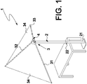
- Figure 1 shows a schematic view of a preferred embodiment of the screen 1 according to the invention.
- the screen is a parasol 1, that is intended for protection from the sun.
- the screen 1 comprises a standard 2, a frame 3, that is attached to the upper side of the standard 2, and control means 22 for controlling the frame 3.
- the frame 3 comprises a fabric 34 and a number of rods for tensioning the fabric 34.
- the fabric 34 is to this end for example provided with hoses or bags for accommodation of the rods.
- the number of rods is three and the rods are independently indicated as 31, 32, 33.
- the standard 2 is optionally placed on a base 21.
- the screen 1 assumes the position of use, in which the frame 3 is unfolded.
- Figure 2A shows the screen 1 in the position of use without fabric and from a different perspective.
- Figure 2B shows the screen 1 in rest position, in which the frame 3 is folded.
- the screen 1 further comprises a head 4, that connects the frame 3 to the standard 2.
- Figure 3 shows a part of the screen 1 in more detail.
- the head 4 is provided with a longitudinal axis 5 upon which the rods 31, 32, 33, are rotatably connected.
- the rods 31, 32, 33 are rotatable using the control means 22 between a rest position, in which the frame 3 is folded and a position of use, in which the frame 3 is unfolded.
- the rotation axis R extends in longitudinal direction through the longitudinal axis 44 of the head 4.
- the head 4 is attached to an end of the standard 2 with the longitudinal axis 44 pointed obliquely upwards.
- the rods 31, 32, 33 extend from the longitudinal axis 44 obliquely downwards.
- Each rod 31, 32, respectively 33 is connected to a hub 41, 42, respectively 43.
- the hubs 41, 42, 43 are arranged adjacent around the longitudinal axis 44.
- the control means 22 are arranged to rotate the longitudinal axis 44.
- the control means comprise a drive shaft (not shown), that extends in the stand 2, and is coupled to the longitudinal axis 44 in the head 4, preferably by means of a universal joint.
- the control means further comprise a handle 22, that is preferably coupled to the drive shaft by means of a worm drive.
- the hub 43 of the rear rod 33 is firmly connected to the longitudinal axis 44. By rotation of the longitudinal axis 44 the hub 43 with the rear rod 33 will rotate along from the rest position and the fabric 43 will begin to unfold.
- the middle hub 42 of the middle rod 32 is arranged freely rotatable around the longitudinal axis 44 and will subsequently be taken along by the fabric 34.
- the head 4 is provided with a locking mechanism for locking at least one of the rods against rotation when the frame 3 has reached the position of use.
- the locking mechanism works on the front rod 31, in particular on the hub 41, and is arranged for locking the hub 41 on the longitudinal axis 44.
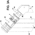
- Figure 3A shows a part of the screen 1 in more detail with exposed head 4.
- Figures 3B and 3C show different views of the hub 41 in a free position.
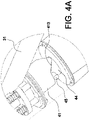
- Figures 4A and 4B show different views of hub 41 in a locked position.
- the hub 41 of the front rod 31 is slidable along the longitudinal axis 44 between a free position, in which the hub is free to rotate around the longitudinal axis, and a locked position, in which the hub cannot rotate around the longitudinal axis.
- the head 4 is provided with positioning means for positioning the hub 41 in the free position.
- the positioning means work against the action of the pre-tensioning means, that push the hub 41 towards the locked position.
- the positioning means are formed by a radially protruding positioning element, for example a pin 45, that is arranged on the longitudinal axis 44.
- the hub 41 is provided with an at least partially obliquely extending positioning edge 413, that abuts the positioning element.
- the positioning edge 413 is generally triangular with a smoothed point, that rests on the pin 45 in the free position.
- the pre-tensioning means are formed by a first flange or collar 47, that is arranged on the longitudinal axis 44, and springs 48, that support on the first flange 47 and work on the hub flange or hub collar 411, that is arranged on the hub 41.
- the pre-tensioning means push the hub 41 downwards along the longitudinal axis 44.
- the locking mechanism comprises a locking element 46 that is arranged on the longitudinal axis 44.
- the locking element 46 is located beneath the first flange 47 and above a second flange or collar 49, that is arranged on the longitudinal axis 44.
- the locking element 46 is for example a key.
- the hub flange 411 is provided with a locking opening 412 for accommodation of the locking element 46.
- the front hub 41 When the front rod 31 is being taken along by the fabric 34 during operation of the screen 1, the front hub 41 will rotate and the positioning edge 413 will slide off the pin 45. Under pressure from the pre-tensioning means the hub 41 will subsequently move downwards along the longitudinal axis 44 and the locking opening 412 will fall over the locking element 46. The front hub 41 of front rod 31 is then locked against rotation around the longitudinal axis 44.
- the frame 3 can be moved from the position of use to the rest position.
- the longitudinal axis 44 By rotation of the longitudinal axis 44 in opposite direction first the rear rod 33 will be driven, after which the middle rod 32 and the frond rod 31 will be taken along.
- the hub 41 of the front rod 31 will be forced out of the locked position into the free position.
- the positioning edge 413 thereby guides the hub 41 over the pin 45 against the action of the pre-tensioning means.
- the frame 3 is to this end provided with appropriate means, for example carriers on the rods and/or in the fabric.
- the invention is based on the thought to provide a sunshade with a fan-shaped frame, preferably with a minimum number of rods.
- the screen is preferably further provided with a locking mechanism that automatically takes effect after unfolding by means of control means.
- the invention is explicitly not limited to the described and shown preferred embodiment.
- the number of rods can be expanded and the shape of the fabric can be adjusted.
- the control means can optionally be electric. These are but some alternative embodiments that lie within the reach of an expert in the field.
Landscapes
- Operating, Guiding And Securing Of Roll- Type Closing Members (AREA)
- Building Awnings And Sunshades (AREA)
Abstract
The invention relates to a screen (1) for protection from the sun, comprising a standard (2), a frame (3) that is attached to the upper side of the standard, wherein the frame comprises a fabric (34) and a number of rods (31, 32, 33) for tensioning the fabric, and control means (22) for controlling the frame (3) between a rest position, in which the frame is folded and a position of use, in which the frame is unfolded. According to the invention the screen further comprises a head (4), that connects the frame (3) to the standard (2). The head is provided with a longitudinal axis, the rods are rotatably connected to the longitudinal axis and are rotatable using the control means between a rest position and a position of use.
Description
- The present invention relates to a screen for protection from the sun, comprising a standard, a frame attached to the upper side of the standard, wherein the frame comprises a fabric and a number of rods for tensioning the fabric, and control means for controlling the frame between a rest position, in which the frame is folded and a position of use in which the frame is unfolded.
- Such a screen is known in the field. Known variants are a pole parasol with a central stand and a cantilever parasol, in which the stand is located out of the centre of the frame.
- The present invention aims to provide a screen of the kind mentioned in the preamble with an improved unfolding mechanism.
- The present invention to this end provides a screen according to the preamble characterized in that, the screen further comprises a head, that connects the frame to the standard, wherein the head is provided with a longitudinal axis, and in that the rods are connected rotatably around the longitudinal axis and are rotatable by means of the control means between the rest position and the position of use. The screen according to the present invention is in a unique way able to unfold like a fan, wherein the fabric is tensioned between adjacent rods. This gives the screen a modern, sleek appearance.
- The screen can be made in various variants by for example varying the orientation of the head relative to the stand. In a first preferred embodiment the head is attached to an end of the standard with the longitudinal axis pointed obliquely upwards. This makes it possible to place the parasol close to other objects, such as a table, without the frame hitting the object during unfolding. According to a further development of the first preferred embodiment the rods extend from the longitudinal axis obliquely downwards and extend primarily parallel to the stand. The screen occupies little space in the rest position.
- In an elegant, preferred embodiment the head comprises a locking mechanism for automatically locking at least one of the rods in the position of use. According to a further development of the elegant, preferred embodiment at least one of the rods is attached to a hub and the locking mechanism is arranged to lock the hub on the longitudinal axis. In a practical preferred embodiment the hub is slidable along the longitudinal axis between a free position, in which the hub is free to rotate around the longitudinal axis, and a locked position, in which the hub cannot rotate around the longitudinal axis. Preferably, the head is provided with pre-tensioning means for pre-tensioning the hub in the locked position. According to a further elegant, preferred embodiment the head is provided with positioning means for positioning the hub in the free position against the action of the pre-tensioning means. In a further practical preferred embodiment the positioning means comprise a radially protruding positioning element arranged on the longitudinal axis and the hub is provided with an at least partially obliquely extending positioning edge that abuts the positioning element. The positioning edge serves as a guiding element for gradually moving the hub between the free position and the locked position. In a reliable preferred embodiment the locking mechanism comprises a locking element arranged on the longitudinal axis and the hub is provided with a flange with a locking opening for accommodation of the locking element.
- According to a stylish preferred embodiment the frame comprises three or more rods, each attached to a hub, wherein the three or more hubs are arranged adjacent around the longitudinal axis, wherein the control means are arranged to rotate one of the outer hubs. It suffices to drive only one of the outer hubs, because the fabric will take the other hubs along with it.
- According to a further stylish preferred embodiment, the locking mechanism is arranged to lock the other outer hub and hubs located between the outer hubs are freely rotatable. It suffices to only lock the other outer hub, which has been moved last.
- In an optimal preferred embodiment the screen comprises three rods. The screen now has an elegant A-frame.
- According to a reliable preferred embodiment the control means comprise a drive shaft, which extends out into the stand, and is coupled to the horizontal axis in the head, preferably by means of a universal joint. The control means further comprise a handle and a worm drive for coupling the handle to the drive shaft. These control means are easy to control, can transfer enough power, are adjustable in a stepless manner and automatically block the driven rod, when it is released.
- The invention will now be discussed in more detail according to the drawings, in which
-
Figure 1 shows a schematic view of a preferred embodiment of the screen according to the invention in a position of use; -
Figure 2A shows the screen offigure 1 without fabric from a different perspective; -
Figure 2B shows the screen offigure 2A in rest position; -
Figure 3A shows a part of the screen offigure 2B in more detail; -
Figure 3B shows a part offigure 3A in more detail; -
Figure 3C shows a different part offigure 3A in more detail; -
Figure 4A shows a part of the screen offigure 2A in more detail; and -
Figure 4B shows a part offigure 4A in more detail. -
Figure 1 shows a schematic view of a preferred embodiment of the screen 1 according to the invention. - In the shown preferred embodiment the screen is a parasol 1, that is intended for protection from the sun. The screen 1 comprises a standard 2, a
frame 3, that is attached to the upper side of the standard 2, and control means 22 for controlling theframe 3. Theframe 3 comprises afabric 34 and a number of rods for tensioning thefabric 34. Thefabric 34 is to this end for example provided with hoses or bags for accommodation of the rods. - In the shown preferred embodiment the number of rods is three and the rods are independently indicated as 31, 32, 33. The
standard 2 is optionally placed on abase 21. Infigure 1 the screen 1 assumes the position of use, in which theframe 3 is unfolded. -
Figure 2A shows the screen 1 in the position of use without fabric and from a different perspective.Figure 2B shows the screen 1 in rest position, in which theframe 3 is folded. - The screen 1 further comprises a
head 4, that connects theframe 3 to the standard 2.Figure 3 shows a part of the screen 1 in more detail. Thehead 4 is provided with a longitudinal axis 5 upon which therods rods frame 3 is folded and a position of use, in which theframe 3 is unfolded. The rotation axis R extends in longitudinal direction through thelongitudinal axis 44 of thehead 4. - In the shown preferred embodiment the
head 4 is attached to an end of the standard 2 with thelongitudinal axis 44 pointed obliquely upwards. Therods longitudinal axis 44 obliquely downwards. Eachrod hub hubs longitudinal axis 44. - The control means 22 are arranged to rotate the
longitudinal axis 44. In the shown preferred embodiment the control means comprise a drive shaft (not shown), that extends in thestand 2, and is coupled to thelongitudinal axis 44 in thehead 4, preferably by means of a universal joint. The control means further comprise ahandle 22, that is preferably coupled to the drive shaft by means of a worm drive. - The
hub 43 of therear rod 33 is firmly connected to thelongitudinal axis 44. By rotation of thelongitudinal axis 44 thehub 43 with therear rod 33 will rotate along from the rest position and thefabric 43 will begin to unfold. Themiddle hub 42 of themiddle rod 32 is arranged freely rotatable around thelongitudinal axis 44 and will subsequently be taken along by thefabric 34. - The
head 4 is provided with a locking mechanism for locking at least one of the rods against rotation when theframe 3 has reached the position of use. In this example the locking mechanism works on thefront rod 31, in particular on thehub 41, and is arranged for locking thehub 41 on thelongitudinal axis 44. - The action of the locking mechanism will be explained on the basis of the following figures.
Figure 3A shows a part of the screen 1 in more detail with exposedhead 4.Figures 3B and3C show different views of thehub 41 in a free position.Figures 4A and4B show different views ofhub 41 in a locked position. - The
hub 41 of thefront rod 31 is slidable along thelongitudinal axis 44 between a free position, in which the hub is free to rotate around the longitudinal axis, and a locked position, in which the hub cannot rotate around the longitudinal axis. - The
head 4 is provided with positioning means for positioning thehub 41 in the free position. The positioning means work against the action of the pre-tensioning means, that push thehub 41 towards the locked position. - In the shown preferred embodiment the positioning means are formed by a radially protruding positioning element, for example a
pin 45, that is arranged on thelongitudinal axis 44. Thehub 41 is provided with an at least partially obliquely extendingpositioning edge 413, that abuts the positioning element. In the shown preferred embodiment thepositioning edge 413 is generally triangular with a smoothed point, that rests on thepin 45 in the free position. - In the shown preferred embodiment the pre-tensioning means are formed by a first flange or
collar 47, that is arranged on thelongitudinal axis 44, and springs 48, that support on thefirst flange 47 and work on the hub flange orhub collar 411, that is arranged on thehub 41. - The pre-tensioning means push the
hub 41 downwards along thelongitudinal axis 44. - The locking mechanism comprises a locking
element 46 that is arranged on thelongitudinal axis 44. The lockingelement 46 is located beneath thefirst flange 47 and above a second flange orcollar 49, that is arranged on thelongitudinal axis 44. The lockingelement 46 is for example a key. Thehub flange 411 is provided with alocking opening 412 for accommodation of the lockingelement 46. - When the
front rod 31 is being taken along by thefabric 34 during operation of the screen 1, thefront hub 41 will rotate and thepositioning edge 413 will slide off thepin 45. Under pressure from the pre-tensioning means thehub 41 will subsequently move downwards along thelongitudinal axis 44 and thelocking opening 412 will fall over the lockingelement 46. Thefront hub 41 offront rod 31 is then locked against rotation around thelongitudinal axis 44. - By means of the control means the
frame 3 can be moved from the position of use to the rest position. By rotation of thelongitudinal axis 44 in opposite direction first therear rod 33 will be driven, after which themiddle rod 32 and thefrond rod 31 will be taken along. Thehub 41 of thefront rod 31 will be forced out of the locked position into the free position. Thepositioning edge 413 thereby guides thehub 41 over thepin 45 against the action of the pre-tensioning means. Theframe 3 is to this end provided with appropriate means, for example carriers on the rods and/or in the fabric. - The invention is based on the thought to provide a sunshade with a fan-shaped frame, preferably with a minimum number of rods. The screen is preferably further provided with a locking mechanism that automatically takes effect after unfolding by means of control means.
- It is noted that the invention is explicitly not limited to the described and shown preferred embodiment. The number of rods can be expanded and the shape of the fabric can be adjusted. The control means can optionally be electric. These are but some alternative embodiments that lie within the reach of an expert in the field.
- The invention therefore extends in general to every embodiment that falls within the scope of the enclosed claims seen in het light of the description and corresponding drawings.
Claims (15)
- Screen for protection from the sun, comprising a standard, a frame attached to the upper side of the standard, wherein the frame comprises a fabric and a number of rods for tensioning the fabric, and control means for controlling the frame between a rest position, in which the frame is folded and a position of use, in which the frame is unfolded, characterized in that the screen further comprises a head, that connects the frame to the standard, wherein the head is provided with a longitudinal axis, and in that the rods are connected rotatably around the longitudinal axis and are rotatable by means of the control means between the rest position and the position of use.
- Screen according to claim 1, wherein the head is attached to an end of the standard with the longitudinal axis pointed obliquely upwards.
- Screen according to claim 2, wherein the rods extend from the longitudinal axis obliquely downwards, such that the rods in the rest position extend primarily parallel to the stand.
- Screen according to claim 1, 2, or 3, wherein the head comprises a locking mechanism for automatically locking at least one of the rods in the position of use.
- Screen according to claim 4, wherein at least one of the rods is attached to a hub and the locking mechanism is arranged to lock the hub on the longitudinal axis.
- Screen according to claim 5, wherein the hub is slidable along the longitudinal axis between a free position, in which the hub is free to rotate around the longitudinal axis, and a locked position, in which the hub cannot rotate around the longitudinal axis.
- Screen according to claim 6, wherein the hub is provided with pre-tensioning means for pre-tensioning the hub in the locked position.
- Screen according to claim 7, wherein the head is provided with positioning means for positioning the hub in the free position against the action of the pre-tensioning means.
- Screen according to claim 8, wherein the positioning means comprise a radially protruding positioning element arranged on the longitudinal axis and the hub is provided with an at least partially obliquely extending positioning edge that abuts the positioning element.
- Screen according to one of the previous claims 5-9, wherein the locking mechanism comprises a locking element arranged on the longitudinal axis and the hub is provided with a flange with a locking opening for accommodation of the locking element.
- Screen according to one of the previous claims, wherein the frame comprises three or more rods, each attached to a hub, wherein the three or more hubs are arranged adjacent around the longitudinal axis, wherein the control means are arranged to rotate one of the outer hubs.
- Screen according to claim 11, with reference to claim 4, wherein the locking mechanism is arranged to lock the other outer hub and wherein hubs located between the outer hubs are freely rotatable.
- Screen according to claim 12, wherein the screen comprises three rods.
- Screen according to one of the previous claims, wherein the control means comprise a drive shaft, that extends out into the stand, and is coupled to the horizontal axis in the head.
- Screen according to claim 14, wherein the control means further comprise a handle and a worm drive for coupling the handle to the drive shaft.
Applications Claiming Priority (1)
| Application Number | Priority Date | Filing Date | Title |
|---|---|---|---|
| NL2027471A NL2027471B1 (en) | 2021-02-01 | 2021-02-01 | SUN SHADE WITH IMPROVED FOLDING MECHANISM |
Publications (1)
| Publication Number | Publication Date |
|---|---|
| EP4035556A1 true EP4035556A1 (en) | 2022-08-03 |
Family
ID=80446918
Family Applications (1)
| Application Number | Title | Priority Date | Filing Date |
|---|---|---|---|
| EP22154417.4A Withdrawn EP4035556A1 (en) | 2021-02-01 | 2022-02-01 | Sun shade with improved unfolding mechanism |
Country Status (2)
| Country | Link |
|---|---|
| EP (1) | EP4035556A1 (en) |
| NL (1) | NL2027471B1 (en) |
Cited By (1)
| Publication number | Priority date | Publication date | Assignee | Title |
|---|---|---|---|---|
| CN115399559A (en) * | 2022-09-04 | 2022-11-29 | 临海市球源工艺品有限公司 | A rotating sunshade |
Citations (4)
| Publication number | Priority date | Publication date | Assignee | Title |
|---|---|---|---|---|
| DE1107904B (en) * | 1955-08-08 | 1961-05-31 | Rosenkaimer Gmbh | Sun shield |
| DE3508851A1 (en) * | 1985-03-13 | 1986-09-25 | Clauss Markisen, 7311 Bissingen | Windshield or sunshade which can be opened out in the manner of a fan and has a drive device |
| DE202010010017U1 (en) * | 2010-07-08 | 2010-10-14 | Bachschmid, Fritz | awning |
| EP3187663A1 (en) * | 2014-08-29 | 2017-07-05 | Iniciativa Exterior 3i S.A. | Sun umbrella |
-
2021
- 2021-02-01 NL NL2027471A patent/NL2027471B1/en active
-
2022
- 2022-02-01 EP EP22154417.4A patent/EP4035556A1/en not_active Withdrawn
Patent Citations (4)
| Publication number | Priority date | Publication date | Assignee | Title |
|---|---|---|---|---|
| DE1107904B (en) * | 1955-08-08 | 1961-05-31 | Rosenkaimer Gmbh | Sun shield |
| DE3508851A1 (en) * | 1985-03-13 | 1986-09-25 | Clauss Markisen, 7311 Bissingen | Windshield or sunshade which can be opened out in the manner of a fan and has a drive device |
| DE202010010017U1 (en) * | 2010-07-08 | 2010-10-14 | Bachschmid, Fritz | awning |
| EP3187663A1 (en) * | 2014-08-29 | 2017-07-05 | Iniciativa Exterior 3i S.A. | Sun umbrella |
Cited By (4)
| Publication number | Priority date | Publication date | Assignee | Title |
|---|---|---|---|---|
| CN115399559A (en) * | 2022-09-04 | 2022-11-29 | 临海市球源工艺品有限公司 | A rotating sunshade |
| EP4331429A1 (en) * | 2022-09-04 | 2024-03-06 | Linhai Qiuyuan Arts & Crafts Co., Ltd. | Rotary open-close type sun umbrella |
| GB2622115A (en) * | 2022-09-04 | 2024-03-06 | Linhai Qiuyuan Arts & Crafts Co Ltd | Rotary open-close type sun umbrella |
| GB2622115B (en) * | 2022-09-04 | 2024-08-28 | Linhai Qiuyuan Arts & Crafts Co Ltd | Rotary open-close type sun umbrella |
Also Published As
| Publication number | Publication date |
|---|---|
| NL2027471B1 (en) | 2022-09-02 |
Similar Documents
| Publication | Publication Date | Title |
|---|---|---|
| CA2358352C (en) | Tiltable and rotatable canopy frame for a sunshade | |
| US5937882A (en) | Umbrella with side support for tilting and opening | |
| AU779526B2 (en) | Free-arm shade | |
| US5579797A (en) | Foldable canopy support | |
| US20020074032A1 (en) | Frame assembly for folding tents | |
| EP0200571B1 (en) | Garden or sun umbrellas | |
| WO2024156277A1 (en) | Cantilever umbrella | |
| US20020121297A1 (en) | Operation device for outdoor umbrella | |
| US7931040B2 (en) | Portable shelter | |
| CA2182991C (en) | Cover assembly for a deck chair | |
| US7347217B2 (en) | Sunshade | |
| CN206453378U (en) | It is a kind of can full angle regulation outdoor sun shade | |
| CN118139559A (en) | A five-in-one umbrella canopy that helps people with arthritis | |
| FR2523420A1 (en) | UMBRELLA HAVING AN OVAL-SHAPED DOME | |
| AU2016227408B2 (en) | Fan-like sun or weather protection device | |
| US2518167A (en) | Sun shelter | |
| KR100511007B1 (en) | Fixed large parasol having foldable awning | |
| KR200461751Y1 (en) | Parasol | |
| KR200340383Y1 (en) | Large parasol foldable by electric motor | |
| NL2027471B1 (en) | SUN SHADE WITH IMPROVED FOLDING MECHANISM | |
| IES62301B2 (en) | A clothes line and canopy arrangement | |
| CN210299841U (en) | Hanging umbrella convenient to adjust | |
| CN210276198U (en) | Sun umbrella with buffering function of opening and closing | |
| CN116849437A (en) | Umbrella opening and closing device | |
| FR2811361A1 (en) | Folding parasol with combined fan has articulated stiffeners carrying canvas and fan blades, driven by motor, secured to control unit folded in same direction as stiffeners when sleeve is slid on parasol base |
Legal Events
| Date | Code | Title | Description |
|---|---|---|---|
| PUAI | Public reference made under article 153(3) epc to a published international application that has entered the european phase |
Free format text: ORIGINAL CODE: 0009012 |
|
| STAA | Information on the status of an ep patent application or granted ep patent |
Free format text: STATUS: THE APPLICATION HAS BEEN PUBLISHED |
|
| AK | Designated contracting states |
Kind code of ref document: A1 Designated state(s): AL AT BE BG CH CY CZ DE DK EE ES FI FR GB GR HR HU IE IS IT LI LT LU LV MC MK MT NL NO PL PT RO RS SE SI SK SM TR |
|
| STAA | Information on the status of an ep patent application or granted ep patent |
Free format text: STATUS: THE APPLICATION IS DEEMED TO BE WITHDRAWN |
|
| 18D | Application deemed to be withdrawn |
Effective date: 20230204 |