EP4035520A1 - Closed loop combine cleaning fan control - Google Patents
Closed loop combine cleaning fan control Download PDFInfo
- Publication number
- EP4035520A1 EP4035520A1 EP22154758.1A EP22154758A EP4035520A1 EP 4035520 A1 EP4035520 A1 EP 4035520A1 EP 22154758 A EP22154758 A EP 22154758A EP 4035520 A1 EP4035520 A1 EP 4035520A1
- Authority
- EP
- European Patent Office
- Prior art keywords
- cleaning system
- air
- duct
- sieves
- sensor
- Prior art date
- Legal status (The legal status is an assumption and is not a legal conclusion. Google has not performed a legal analysis and makes no representation as to the accuracy of the status listed.)
- Granted
Links
Images

Classifications
-
- A—HUMAN NECESSITIES
- A01—AGRICULTURE; FORESTRY; ANIMAL HUSBANDRY; HUNTING; TRAPPING; FISHING
- A01F—PROCESSING OF HARVESTED PRODUCE; HAY OR STRAW PRESSES; DEVICES FOR STORING AGRICULTURAL OR HORTICULTURAL PRODUCE
- A01F12/00—Parts or details of threshing apparatus
- A01F12/44—Grain cleaners; Grain separators
- A01F12/444—Fanning means
-
- A—HUMAN NECESSITIES
- A01—AGRICULTURE; FORESTRY; ANIMAL HUSBANDRY; HUNTING; TRAPPING; FISHING
- A01D—HARVESTING; MOWING
- A01D41/00—Combines, i.e. harvesters or mowers combined with threshing devices
-
- A—HUMAN NECESSITIES
- A01—AGRICULTURE; FORESTRY; ANIMAL HUSBANDRY; HUNTING; TRAPPING; FISHING
- A01D—HARVESTING; MOWING
- A01D41/00—Combines, i.e. harvesters or mowers combined with threshing devices
- A01D41/12—Details of combines
- A01D41/127—Control or measuring arrangements specially adapted for combines
- A01D41/1276—Control or measuring arrangements specially adapted for combines for cleaning mechanisms
-
- A—HUMAN NECESSITIES
- A01—AGRICULTURE; FORESTRY; ANIMAL HUSBANDRY; HUNTING; TRAPPING; FISHING
- A01F—PROCESSING OF HARVESTED PRODUCE; HAY OR STRAW PRESSES; DEVICES FOR STORING AGRICULTURAL OR HORTICULTURAL PRODUCE
- A01F12/00—Parts or details of threshing apparatus
- A01F12/44—Grain cleaners; Grain separators
- A01F12/446—Sieving means
Definitions
- the present invention relates to a cleaning system of agricultural equipment, such as a combine harvester.
- a cleaning system for a combine harvester includes a fan assembly that is configured to blow air through reciprocating sieves to carry lighter elements of material other than grain (MOG) or chaff away.
- Transverse or cross-flow fans of various designs have been advantageously employed with agricultural combines to provide the air that is blown upwardly and rearwardly through the sieves to carry the chaff away from the grain and tailings deposited onto the cleaning system sieves.
- Transverse fans are useful in combine cleaning systems because such fans can produce a wide stream of air that can be directed upwardly toward the cleaning sieves of the combine cleaning systems but require relatively little space.
- Such fans in typical agricultural combines, are disposed such that their air outlet ports are below the sieves of the cleaning system.
- transverse fans One problem with transverse fans is that the air blowing through the fan housing will receive air through its inlet in a uniform manner, however, the air can be unevenly distributed through the outlet ports of the fan. This problem may occur during the process of loading and unloading the sieves.
- the air within the fan housing will typically follow the path of least resistance, namely, toward the unobstructed portion of the sieves. This may be referred to in the art as a blowout condition.
- the disclosure is generally directed to a cleaning system of a combine harvester.
- a cleaning system of a combine harvester comprises:
- each sensor is a pressure transducer, a pressure switch, or a strain gauge.
- a combine harvester comprising the cleaning system.
- the combine harvester further comprises a rotor and concave that are positioned at an elevation above the cleaning system.
- a method for operating a cleaning system comprises:
- the first sensor is mounted to a housing for the first sieve
- the second sensor is mounted to a housing for the second sieve.
- the first sensor may at least partially be positioned within the first duct, and the second sensor may at least partially be positioned within the second duct.
- each valve member is pivotally connected to the fan housing.
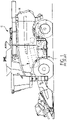
- FIGS. 1 and 2 which are reproduced from U.S. Patent No. 8,221,064 , identify the general location of and depict a conventional transverse fan assembly 10 arranged in operable combination with a typical, conventional, self-propelled agricultural combine harvester 12 of the axial-flow type wherein crop material is threshed and separated while it is advanced by and along a generally longitudinally arranged rotor.
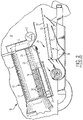
- a threshing apparatus 18 of the combine harvester 12 includes a rotor assembly 20, including a relatively large diameter rotor 22 that is mounted within a threshing cage 24. Disposed about the cage 24 is a system of concaves 26 and separating grates 28 which, through the action of the rotor 22 and centrifugal force, act to separate grain material from other crop residue that is too large to pass through the concaves 26 and grates 28, sometimes hereafter referred to as straw.
- the threshed grain material is delivered to a cleaning system 29 that includes a pair of vertically spaced apart cleaning sieves 30 and 32 while the straw is propelled rearwardly through the rotor assembly 20 where a conventional beater 40 acts upon the crop residue discharged from the rotor assembly 20.
- Beater 40 propels the crop residue from the rear of the rotor assembly 20 and throws it back for broad discharge from the rear end of the combine.
- an auger 34 moves the threshed grain material to the cleaning sieves 30 and 32, which sieves form part of the cleaning system 29 and are mounted for oscillation to separate grain from other larger pieces of threshed crop material.
- the sieves 30 and 32 are vibrated or oscillated, the grain falls through the sieves 30 and 32 to an underlying clean grain pan 35 and into a clean grain trough or collector 36.
- An auger 38 directs the grain from the clean grain trough 36 into a hopper or grain bin (not shown) often housed generally directly behind the cab 12 ( FIG. 1 ) within combine harvester body 14.
- the threshed grain material that is too large to fall through the sieves 30 and 32 forms a relatively large crop mat or veil extending across substantially the entire sieve construction, as fan assembly 10 provides air that is blown upwardly and rearwardly, as denoted by the arrows, through sieves 30 and 32.
- Such air flow acts to blow lighter, non-grain elements, sometimes referred to as chaff, away from the crop mat remaining on the sieves 30 and 32 towards the rear of the harvester, where such chaff is handled in conventional and well-known manners.
- the fan assembly 301 shown in FIG. 2 includes a single outlet port directed to sieves 30 and 32, however, other fan assemblies include multiple outlet ports, such as the fan shown in FIG. 3 .
- a first outlet port is positioned to direct air to a first sieve (commonly referred to as a "pre-sieve")
- a second outlet port is positioned to direct air to one or more additional sieves (e.g., chaffer sieves).
- a first sieve commonly referred to as a "pre-sieve”
- additional sieves e.g., chaffer sieves
- FIG. 3 there is illustrated a cleaning system 300 for a combine harvester, in accordance with an exemplary embodiment.
- Cleaning system 300 may be used with the combine of FIG. 1 or a different combine.
- the cleaning system 300 comprises a transverse fan assembly 301 and a cleaning shoe 309.
- the cleaning shoe comprises, at least in part, sieves 309a-309c.
- the fan assembly 301 may replace the fan assembly 10 of FIGs. 1 and 2 in the combine harvester.
- the sieves 309a-309c may replace the sieves 30 and 32.
- the fan assembly 301 includes a housing 302 having a series of panels that are mounted together to form an interconnected housing.
- the fan assembly 301 includes an air inlet 303 at its top end.
- the fan assembly 301 includes two exhaust or outlet openings 304 and 306 through which air is exhausted.
- Behind the front panel 307 is disposed a curved divider 308 positioned between the exhaust openings 304 and 306.
- the curved divider 308 serves to separate the inlet air flow 350 into two different exhaust flow streams, namely, exhaust air flow 354 and exhaust air flow 356.
- the fan assembly 301 includes a single, unitary rotor 310.
- the rotor 310 includes a series of blades 312 for drawing air through the housing 302 from the inlet 303 to the outlets openings 304 and 306.
- the rotor 310 may be driven by a single drive.
- a first valve member 320a is positioned within the duct 322 leading to the first outlet opening 304.
- First valve member 320a is pivotably connected to the divider 308 by a pivot point 323, bearing or hinge.
- the location of first valve member 320a within the duct 322 may vary, and, the location of the pivot point 323 may also vary.
- Valve member 320a may extend to a length that is either equal to the space in the duct 322 (as shown), or less than that space.
- an actuator 402a is configured to rotate the first valve member 320a about pivot point 323 and within the duct 322 (see arrows) based upon instructions received from a controller 404.
- Actuator 402a may be actuated either electrically or hydraulically, for example.
- Actuator 402a could be a solenoid, gear motor, or hydraulic piston, for example.
- First valve member 320a is configured to be moved between a fully-closed position (not shown) and a fully open position (shown) by actuator 402a. In the fully-closed position, the first valve member 320a is rotated to a position such that it prevents the air flow 354 from being expelled through the outlet opening 304. In a fully-open position, the first valve member 320a is rotated to a position such that it does not prevent the air flow 354 from being expelled through the outlet opening 304. In operation, the first valve member 320a may be rotated to any predetermined position that is defined between the fully-open and fully-closed positions.
- a second valve member 320b is positioned within the duct 324 leading to the second outlet opening 306.
- an actuator 402b is configured to rotate the second valve member 320b within the duct 324 (see arrows) based upon instructions received from controller 404.
- Valve member 320b and actuator 402b share the same structure and function as the valve member 320a and actuator 402a, and will not be described further.
- Cleaning shoe 309 comprises a shoe housing 351 (only a portion of which is shown) to which the sieves 309a-309c are connected. The function of a cleaning shoe is well understood in the art. Located beneath each sieve 309a-309c is a pressure sensor 352a-352c, respectively. Each pressure sensor 352a-352c may be mounted directly to shoe housing 350. Each pressure sensor 352a-352c is configured to sense the air pressure being delivered by the fan 301 onto the respective sieves 309a-309c, respectively, via the outlet openings 304/306. Sensors 352a-352c transmit the air pressure readings to controller 404.
- a second set of pressure sensors 360a and 360b are positioned within the ducts 322 and 324, respectively.
- Pressure sensors 360a and 360b sense the air pressure being delivered through the ducts 322 and 324, respectively.
- Pressure sensors 360a and 360b also sense any backpressure caused by loading of the sieves 309, which is communicated via ducts 322 and 324, respectively.
- pressure sensor 352a can sense backpressure caused by crop loading at sieve 309a.
- pressure sensor 352a senses an air pressure that is indicative of the air pressure at sieve 309a. It can also be stated that air pressure sensor 352a is 'near' sieve 309a because it is positioned within the air duct that faces the sieve 309a.
- Pressure sensors 352 and 360 may be any conventional, off-the-shelf, pressure transducer, pressure switch, or strain gauge, for example. Other styles of pressure sensors are known to those skilled in the art.
- system 300 includes pressure sensors 360 and pressure sensors 352.
- system 300 includes pressure sensors 352, but not pressure sensors 360.
- system 300 includes pressure sensors 360, but not pressure sensors 352.
- Sensors 352 may be provided on a conventional cleaning system to serve other purposes such as monitoring the air pressure in the sieves, whereby the monitored air pressures are used for adjusting the sieve opening and fan speed based upon the monitored air pressure.
- cleaning system 300 may take advantage of existing sensors in a combine harvester.
- FIG. 4 depicts a schematic diagram of a system 400 for controlling air flow in the cleaning system 300.
- cleaning system 300 can include sensors 352 and/or sensors 360.
- Controller 404 receives pressure readings transmitted from sensors 352 and/or sensors 360.
- Controller 404 analyzes the pressure readings to determine the pressure level at the ducts 322 and 324 and/or the sieves 309 and identifies any imbalance in pressures between the ducts 322 and 324 and at the sieves 309.
- the controller 404 can include a memory having a table of valve positions related to desired air pressure values.
- controller 404 Based upon the pressure readings transmitted from sensors 352 and/or sensors 360, the controller 404 activates the actuators 402a and/or 402b to adjust the rotational positions of the valves 320a and 320b between their open and closed positions, respectively, thereby affecting the air flow at the sieves 309. Communications between controller 404 and sensors and actuators may be either wired or wireless.
- sensor 352a may measure a higher air pressure than pressure sensors 352b and 352c indicating that the air pressure at sieve 309a is higher than the air pressure at sieves 309b and 309c. Accordingly, based upon the measured pressures, the controller 404 would either (i) move valve 320a closer toward its closed position (by way of actuator 402a), or (ii) move valve 320b closer toward its open position (by way of actuator 402b), in order to increase the air flow to sieves 309b and 309c.
- Controller 404 may be configured to (i) maintain equal air pressure at the sieves, (ii) maintain the air pressure at each sieve at a pre-defined pressure, or (iii) maintain the air pressure at the sieves at a pre-defined differential (e.g., 60% air flow to sieve 309a, and 40% air flow to sieves 309b and 309c).
- a pre-defined differential e.g., 60% air flow to sieve 309a, and 40% air flow to sieves 309b and 309c.
- FIG. 5 depicts a flow chart showing an exemplary closed loop method or routine 500 for operating the cleaning system of FIG. 3 .
- routine 500 at step 502, sensors 352 and/or 360 transmit the local air pressures to controller 404.
- controller 404 determines the air pressure at each sieve 309 (either directly via sensors 352 or indirectly via sensors 360), and then calculates a deviance (i.e., an error) from a desired air pressure at each sieve 309 using an algorithm.
- a deviance i.e., an error
- the controller 404 transmits instructions (in the form of an error signal) to actuators 402 in order to change the position of one or more valves 320 within their ducts, in an effort to maintain the air pressure at the sieves at the desired air pressures.
- the routine 500 then returns to step 502 to monitor the local air pressures that were adjusted at step 506, and proceeds to adjust the valves 320 again at step 506 , if necessary.
- the controller 404 may utilize a proportional-integral-derivative (PID) loop to eventually reach the desired air pressure at each sieve 309. It should be understood that system 400 is a closed loop system.
- the operational steps are performed by the controller 404 upon loading and executing software code or instructions which are tangibly stored on a tangible computer readable medium, such as on a magnetic medium, e.g., a computer hard drive, an optical medium, e.g., an optical disc, solid-state memory, e.g., flash memory, or other storage media known in the art.
- a tangible computer readable medium such as on a magnetic medium, e.g., a computer hard drive, an optical medium, e.g., an optical disc, solid-state memory, e.g., flash memory, or other storage media known in the art.
- any of the functionality performed by the controller 404 described herein is implemented in software code or instructions which are tangibly stored on a tangible computer readable medium.
- the controller may perform any of the functionality of the controller described herein, including any steps of the methods described herein.
- software code or “code” used herein refers to any instructions or set of instructions that influence the operation of a computer or controller 404. They may exist in a computer-executable form, such as machine code, which is the set of instructions and data directly executed by a computer's central processing unit or by a controller, a human-understandable form, such as source code, which may be compiled in order to be executed by a computer's central processing unit or by a controller, or an intermediate form, such as object code, which is produced by a compiler.
- the term "software code” or “code” also includes any human-understandable computer instructions or set of instructions, e.g., a script, that may be executed on the fly with the aid of an interpreter executed by a computer's central processing unit or by a controller.
Landscapes
- Life Sciences & Earth Sciences (AREA)
- Environmental Sciences (AREA)
- Threshing Machine Elements (AREA)
Abstract
Description
- The present invention relates to a cleaning system of agricultural equipment, such as a combine harvester.
- As is described in
U.S. Patent No. 8,221,064 to CNH America LLC, a cleaning system for a combine harvester includes a fan assembly that is configured to blow air through reciprocating sieves to carry lighter elements of material other than grain (MOG) or chaff away. - Transverse or cross-flow fans of various designs have been advantageously employed with agricultural combines to provide the air that is blown upwardly and rearwardly through the sieves to carry the chaff away from the grain and tailings deposited onto the cleaning system sieves. Transverse fans are useful in combine cleaning systems because such fans can produce a wide stream of air that can be directed upwardly toward the cleaning sieves of the combine cleaning systems but require relatively little space. Such fans, in typical agricultural combines, are disposed such that their air outlet ports are below the sieves of the cleaning system.
- One problem with transverse fans is that the air blowing through the fan housing will receive air through its inlet in a uniform manner, however, the air can be unevenly distributed through the outlet ports of the fan. This problem may occur during the process of loading and unloading the sieves. The air within the fan housing will typically follow the path of least resistance, namely, toward the unobstructed portion of the sieves. This may be referred to in the art as a blowout condition.
- It would be desirable to provide uniform distribution of air through the outlet ports of the fan assembly in order to improve cleaning efficiency, crop processing, and either limit or prevent a blowout condition. It would also be desirable to achieve the aforementioned uniform distribution of air in an automated manner.
- The disclosure is generally directed to a cleaning system of a combine harvester.
- According to one aspect of the invention, a cleaning system of a combine harvester comprises:
- a fan assembly comprising a housing, a fan rotor, at least one inlet duct through which air is delivered into the housing, a first duct leading to a first outlet port through which air is exhausted outside of the housing, and a second duct leading to a second outlet port through which air is also exhausted outside of the housing,
- a first valve member positioned within the first duct for throttling the flow of air through the first duct;
- a second valve member positioned within the second duct for throttling the flow of air through the second duct;
- a first actuator for adjusting a position of the first valve member within the first duct;
- a second actuator for adjusting a position of the second valve member within the second duct;
- a first sieve positioned adjacent the first outlet duct to receive a flow of air from the first outlet duct;
- a second sieve positioned adjacent the second outlet duct to receive a flow of air from the second outlet duct;
- a first sensor for either directly or indirectly sensing an air pressure at the first sieve;
- a second sensor for either directly or indirectly sensing an air pressure at the second sieve; and
- a controller configured to receive the sensed air pressures from the first and second sensors, compare the sensed air pressures with either each other or threshold values, and transmit instructions to one or both of the first and second actuators to adjust the positions of one or both of the first and second valve members based upon the comparison.
- Preferably, each sensor is a pressure transducer, a pressure switch, or a strain gauge.
- According to an aspect of the invention, a combine harvester comprising the cleaning system is provided. Preferably, the combine harvester further comprises a rotor and concave that are positioned at an elevation above the cleaning system.
- According to another aspect of the invention, a method for operating a cleaning system comprises:
- receiving, at a controller, air pressure measurements from first and second pressure sensors located either at or near first and second sieves of the cleaning system;
- comparing, using the controller, the air pressure measurements with either each other or threshold valves; and
- adjusting a position of first and/or second valve members within first and second ducts of a fan housing of the cleaning system, respectively, by way of the controller, to change the air pressure at the first and second sieves.
- Preferably, the first sensor is mounted to a housing for the first sieve, and the second sensor is mounted to a housing for the second sieve.
- The first sensor may at least partially be positioned within the first duct, and the second sensor may at least partially be positioned within the second duct.
- Preferably, each valve member is pivotally connected to the fan housing.
- The above-mentioned and other features and advantages of this invention, and the manner of attaining them, will become more apparent and the invention will be better understood by reference to the following description of an embodiment of the invention taken in conjunction with the accompanying drawings, wherein:
-
FIG. 1 a left side view of a conventional combine harvester, in which a transverse fan assembly is installed in conjunction with a cleaning system. -
FIG. 2 is a partial cross-sectional view of a portion of the combine harvester ofFIG. 1 . -
FIG. 3 depicts a schematic cross-sectional side elevation view of a different cleaning assembly for use with the combine harvester ofFIG. 2 or a different combine harvester. -
FIG. 4 depicts a schematic diagram of a closed loop system for controlling air flow in the cleaning system ofFIG. 3 . -
FIG. 5 depicts a flow chart showing an exemplary closed loop process for operating the cleaning system ofFIG. 3 . - Corresponding reference characters indicate corresponding parts throughout the several views. The exemplification set out herein illustrates an embodiment of the invention, in one form, and such exemplification is not to be construed as limiting the scope of the invention in any manner.
- It should be appreciated that, while the following discussion will be directed principally to cleaning system embodiments as employed in such a combine harvester, the cleaning systems of the present invention are not limited to use in such harvesters, but could equally as well be employed or utilized in or with other harvesters and equipment, or with other equipment or in other circumstances and situations, consistent with the principles and teachings expounded.
- For convenience of reference and understanding in the following discussions, and with respect to the various drawings and their descriptions, the point of reference for the use of various terms that are hereafter employed, including "left", "right", "forward", "rearward", "front", "back", "top", and "bottom", should generally be considered to be taken from a point at the rear of the machine facing in its normal direction of travel, unless it is clear from the discussion and context that a different point of reference is appropriate. Any use of such terms should therefore be considered exemplary and should not be construed as limiting or introducing limitations.
- Moreover, inasmuch as various components and features of harvesters and fan assemblies are of well-known design, construction, and operation to those skilled in the art, the details of such components and their operations will not generally be discussed in significant detail unless considered of pertinence to the present invention or desirable for purposes of better understanding.
-
FIGS. 1 and2 , which are reproduced fromU.S. Patent No. 8,221,064 , identify the general location of and depict a conventionaltransverse fan assembly 10 arranged in operable combination with a typical, conventional, self-propelledagricultural combine harvester 12 of the axial-flow type wherein crop material is threshed and separated while it is advanced by and along a generally longitudinally arranged rotor. - As is well known in the art, and as is better illustrated in
FIG. 2 , athreshing apparatus 18 of thecombine harvester 12 includes arotor assembly 20, including a relativelylarge diameter rotor 22 that is mounted within athreshing cage 24. Disposed about thecage 24 is a system of concaves 26 and separatinggrates 28 which, through the action of therotor 22 and centrifugal force, act to separate grain material from other crop residue that is too large to pass through theconcaves 26 andgrates 28, sometimes hereafter referred to as straw. - The threshed grain material is delivered to a
cleaning system 29 that includes a pair of vertically spaced apart cleaningsieves rotor assembly 20 where a conventional beater 40 acts upon the crop residue discharged from therotor assembly 20. Beater 40 propels the crop residue from the rear of therotor assembly 20 and throws it back for broad discharge from the rear end of the combine. - As may be observed from
FIG. 2 , anauger 34 moves the threshed grain material to thecleaning sieves cleaning system 29 and are mounted for oscillation to separate grain from other larger pieces of threshed crop material. As thesieves sieves clean grain pan 35 and into a clean grain trough orcollector 36. Anauger 38 directs the grain from theclean grain trough 36 into a hopper or grain bin (not shown) often housed generally directly behind the cab 12 (FIG. 1 ) withincombine harvester body 14. - The threshed grain material that is too large to fall through the
sieves fan assembly 10 provides air that is blown upwardly and rearwardly, as denoted by the arrows, throughsieves sieves - The
fan assembly 301 shown inFIG. 2 includes a single outlet port directed tosieves FIG. 3 . For example, a first outlet port is positioned to direct air to a first sieve (commonly referred to as a "pre-sieve"), and a second outlet port is positioned to direct air to one or more additional sieves (e.g., chaffer sieves). As is described above, in fan assemblies having multiple outlet ports, one problem is that air can be unevenly distributed through the outlet ports during the loading and unloading processes. - Turning now to
FIG. 3 , there is illustrated acleaning system 300 for a combine harvester, in accordance with an exemplary embodiment.Cleaning system 300 may be used with the combine ofFIG. 1 or a different combine. Thecleaning system 300 comprises atransverse fan assembly 301 and acleaning shoe 309. The cleaning shoe comprises, at least in part,sieves 309a-309c. Thefan assembly 301 may replace thefan assembly 10 ofFIGs. 1 and2 in the combine harvester. And, thesieves 309a-309c may replace thesieves - The
fan assembly 301 includes ahousing 302 having a series of panels that are mounted together to form an interconnected housing. Thefan assembly 301 includes anair inlet 303 at its top end. Unlike thefan assembly 10 ofFIG. 2 , thefan assembly 301 includes two exhaust oroutlet openings front panel 307 is disposed acurved divider 308 positioned between theexhaust openings curved divider 308 serves to separate theinlet air flow 350 into two different exhaust flow streams, namely,exhaust air flow 354 andexhaust air flow 356. - The
fan assembly 301 includes a single, unitary rotor 310. The rotor 310 includes a series of blades 312 for drawing air through thehousing 302 from theinlet 303 to theoutlets openings - A
first valve member 320a is positioned within theduct 322 leading to thefirst outlet opening 304.First valve member 320a is pivotably connected to thedivider 308 by apivot point 323, bearing or hinge. The location offirst valve member 320a within theduct 322 may vary, and, the location of thepivot point 323 may also vary.Valve member 320a may extend to a length that is either equal to the space in the duct 322 (as shown), or less than that space. - Although not shown in
FIG. 3 , anactuator 402a is configured to rotate thefirst valve member 320a aboutpivot point 323 and within the duct 322 (see arrows) based upon instructions received from acontroller 404.Actuator 402a may be actuated either electrically or hydraulically, for example.Actuator 402a could be a solenoid, gear motor, or hydraulic piston, for example. -
First valve member 320a is configured to be moved between a fully-closed position (not shown) and a fully open position (shown) byactuator 402a. In the fully-closed position, thefirst valve member 320a is rotated to a position such that it prevents theair flow 354 from being expelled through theoutlet opening 304. In a fully-open position, thefirst valve member 320a is rotated to a position such that it does not prevent theair flow 354 from being expelled through theoutlet opening 304. In operation, thefirst valve member 320a may be rotated to any predetermined position that is defined between the fully-open and fully-closed positions. - Similarly, a
second valve member 320b is positioned within theduct 324 leading to the second outlet opening 306. Although not shown inFIG. 3 , anactuator 402b is configured to rotate thesecond valve member 320b within the duct 324 (see arrows) based upon instructions received fromcontroller 404.Valve member 320b andactuator 402b share the same structure and function as thevalve member 320a andactuator 402a, and will not be described further. -
Cleaning shoe 309 comprises a shoe housing 351 (only a portion of which is shown) to which thesieves 309a-309c are connected. The function of a cleaning shoe is well understood in the art. Located beneath eachsieve 309a-309c is apressure sensor 352a-352c, respectively. Eachpressure sensor 352a-352c may be mounted directly toshoe housing 350. Eachpressure sensor 352a-352c is configured to sense the air pressure being delivered by thefan 301 onto therespective sieves 309a-309c, respectively, via theoutlet openings 304/306.Sensors 352a-352c transmit the air pressure readings tocontroller 404. - A second set of
pressure sensors ducts Pressure sensors ducts Pressure sensors sieves 309, which is communicated viaducts pressure sensor 352a can sense backpressure caused by crop loading atsieve 309a. And,pressure sensor 352a senses an air pressure that is indicative of the air pressure atsieve 309a. It can also be stated thatair pressure sensor 352a is 'near'sieve 309a because it is positioned within the air duct that faces thesieve 309a. - Pressure sensors 352 and 360 may be any conventional, off-the-shelf, pressure transducer, pressure switch, or strain gauge, for example. Other styles of pressure sensors are known to those skilled in the art.
- According to the embodiment shown,
system 300 includes pressure sensors 360 and pressure sensors 352. According to another embodiment,system 300 includes pressure sensors 352, but not pressure sensors 360. According to yet another embodiment,system 300 includes pressure sensors 360, but not pressure sensors 352. Sensors 352 may be provided on a conventional cleaning system to serve other purposes such as monitoring the air pressure in the sieves, whereby the monitored air pressures are used for adjusting the sieve opening and fan speed based upon the monitored air pressure. Thus,cleaning system 300 may take advantage of existing sensors in a combine harvester. -
FIG. 4 depicts a schematic diagram of a system 400 for controlling air flow in thecleaning system 300. As noted above,cleaning system 300 can include sensors 352 and/or sensors 360.Controller 404 receives pressure readings transmitted from sensors 352 and/or sensors 360.Controller 404 analyzes the pressure readings to determine the pressure level at theducts sieves 309 and identifies any imbalance in pressures between theducts sieves 309. Thecontroller 404 can include a memory having a table of valve positions related to desired air pressure values. Based upon the pressure readings transmitted from sensors 352 and/or sensors 360, thecontroller 404 activates theactuators 402a and/or 402b to adjust the rotational positions of thevalves sieves 309. Communications betweencontroller 404 and sensors and actuators may be either wired or wireless. - For example,
sensor 352a may measure a higher air pressure thanpressure sensors sieve 309a is higher than the air pressure atsieves controller 404 would either (i) movevalve 320a closer toward its closed position (by way of actuator 402a), or (ii) movevalve 320b closer toward its open position (by way ofactuator 402b), in order to increase the air flow tosieves Controller 404 may be configured to (i) maintain equal air pressure at the sieves, (ii) maintain the air pressure at each sieve at a pre-defined pressure, or (iii) maintain the air pressure at the sieves at a pre-defined differential (e.g., 60% air flow to sieve 309a, and 40% air flow tosieves -
FIG. 5 depicts a flow chart showing an exemplary closed loop method or routine 500 for operating the cleaning system ofFIG. 3 . According to routine 500, atstep 502, sensors 352 and/or 360 transmit the local air pressures tocontroller 404. Atstep 504,controller 404 determines the air pressure at each sieve 309 (either directly via sensors 352 or indirectly via sensors 360), and then calculates a deviance (i.e., an error) from a desired air pressure at eachsieve 309 using an algorithm. Atstep 506, and if required due to the occurrence of a deviance, thecontroller 404 transmits instructions (in the form of an error signal) to actuators 402 in order to change the position of one or more valves 320 within their ducts, in an effort to maintain the air pressure at the sieves at the desired air pressures. The routine 500 then returns to step 502 to monitor the local air pressures that were adjusted atstep 506, and proceeds to adjust the valves 320 again atstep 506 , if necessary. Thecontroller 404 may utilize a proportional-integral-derivative (PID) loop to eventually reach the desired air pressure at eachsieve 309. It should be understood that system 400 is a closed loop system. - It is to be understood that the operational steps are performed by the
controller 404 upon loading and executing software code or instructions which are tangibly stored on a tangible computer readable medium, such as on a magnetic medium, e.g., a computer hard drive, an optical medium, e.g., an optical disc, solid-state memory, e.g., flash memory, or other storage media known in the art. Thus, any of the functionality performed by thecontroller 404 described herein is implemented in software code or instructions which are tangibly stored on a tangible computer readable medium. Upon loading and executing such software code or instructions by thecontroller 404, the controller may perform any of the functionality of the controller described herein, including any steps of the methods described herein. - The term "software code" or "code" used herein refers to any instructions or set of instructions that influence the operation of a computer or
controller 404. They may exist in a computer-executable form, such as machine code, which is the set of instructions and data directly executed by a computer's central processing unit or by a controller, a human-understandable form, such as source code, which may be compiled in order to be executed by a computer's central processing unit or by a controller, or an intermediate form, such as object code, which is produced by a compiler. As used herein, the term "software code" or "code" also includes any human-understandable computer instructions or set of instructions, e.g., a script, that may be executed on the fly with the aid of an interpreter executed by a computer's central processing unit or by a controller. - While this invention has been described with respect to at least one embodiment, the present invention can be further modified within the spirit and scope of this disclosure. This application is therefore intended to cover any variations, uses, or adaptations of the invention using its general principles. Further, this application is intended to cover such departures from the present disclosure as come within known or customary practice in the art to which this invention pertains and which fall within the limits of the appended claims.
Claims (15)
- A cleaning system (300) of a combine harvester (10) comprising a fan assembly (301) comprising a housing (302), a fan rotor (310) at least partially positioned within the housing, and at least one inlet duct (303) through which air is delivered into the housing, characterized in that the cleaning system further comprises:a first duct (322) leading to a first outlet port (304) through which air is exhausted outside of the housing, and a second duct (324) leading to a second outlet port (306) through which air is also exhausted outside of the housing,a first valve member (320a) positioned within the first duct for throttling the flow of air through the first duct;a second valve member (320b) positioned within the second duct for throttling the flow of air through the second duct;a first actuator (402a) for adjusting a position of the first valve member within the first duct;a second actuator (402b) for adjusting a position of the second valve member within the second duct;a first sieve (309a) positioned adjacent the first outlet port to receive a flow of air from the first duct;a second sieve (309b/309c) positioned adjacent the second outlet port to receive a flow of air from the second duct;a first sensor (352a/360a) for either directly or indirectly sensing an air pressure at the first sieve;a second sensor (352b/352c/360b) for either directly or indirectly sensing an air pressure at the second sieve; anda controller (404) configured to receive the sensed air pressures from the first and second sensors, compare the sensed air pressures with either each other or threshold values, and transmit instructions to one or both of the first and second actuators to adjust the positions of one or both of the first and second valve members based upon the comparison and thereby adjust the flow of air to the first and/or second sieves.
- The cleaning system (300) of claim 1, characterized in that at least one partition (308) is disposed between the first and second ducts.
- The cleaning system (300) of claim 1, characterized in that each of the first and second sieves includes openings through which grain can pass.
- The cleaning system (300) of claim 1, characterized in that the first sensor (352a) is mounted to a housing (351) for the first sieve, and the second sensor (352c/352c) is mounted to a housing (351) for the second sieve (309b/309c).
- The cleaning system (300) of claim 1, characterized in that the first sensor (360a) is at least partially positioned within the first duct, and the second sensor (360b) is at least partially positioned within the second duct.
- The cleaning system (300) of claim 1, characterized in that each valve member is pivotably connected to the housing of the fan assembly.
- The cleaning system (300) of claim 1, characterized in that the first sensor (352a) is positioned directly below the first sieve (309a), and the second sensor (352b/352c) is positioned directly below the second sieve (309b/309c).
- The cleaning system (300) of claim 1, characterized in that the first sensor (352a/360a) is positioned downstream of the first valve member (320a), and the second sensor (360b/352b/352c) is positioned downstream of the second valve member (320b).
- The cleaning system (300) of claim 1, characterized in that the sieves (309) form part of a cleaning shoe.
- The cleaning system (300) of claim 1, characterized in that the controller (404) is configured to employ a PID loop for adjusting the position of the first and/or second valve members until the sensed air pressures arrive at predetermined values.
- The cleaning system (300) of claim 1, characterized in that the controller (404) is configured to adjust the position of the first and/or second valve members until the sensed air pressures are either equivalent or a difference between the sensed air pressures is maintained within a predefined threshold.
- A combine harvester comprising the cleaning system (300) of claim 1.
- A method for operating a cleaning system (300) of a combine harvester (10), characterized in that said method includes the following steps:receiving, at a controller (404), air pressure measurements from first and second pressure sensors (360a/360b/352a/352b/352c) located either at or near first and second sieves (309) of the cleaning system;comparing, using the controller, the air pressure measurements with either each other or threshold valves; andadjusting a position of first and/or second valve members (320a/320b) within first and second ducts (322/324) of a fan housing (302) of the cleaning system, respectively, by way of the controller, to change the air pressure at the first and/or second sieves (309).
- The method of claim 13, characterized in that the method further comprises, following the adjusting step, receiving, at the controller, further air pressure measurements at the first and second sieves of the cleaning system.
- The method of claim 13, characterized in that the method comprises operating the cleaning system while threshing grain using a rotor (22) and concave (26) of a combine harvester.
Applications Claiming Priority (1)
| Application Number | Priority Date | Filing Date | Title |
|---|---|---|---|
| US17/165,079 US11944040B2 (en) | 2021-02-02 | 2021-02-02 | Closed loop combine cleaning fan control |
Publications (2)
| Publication Number | Publication Date |
|---|---|
| EP4035520A1 true EP4035520A1 (en) | 2022-08-03 |
| EP4035520B1 EP4035520B1 (en) | 2025-09-03 |
Family
ID=80119282
Family Applications (1)
| Application Number | Title | Priority Date | Filing Date |
|---|---|---|---|
| EP22154758.1A Active EP4035520B1 (en) | 2021-02-02 | 2022-02-02 | Closed loop combine cleaning fan control |
Country Status (3)
| Country | Link |
|---|---|
| US (1) | US11944040B2 (en) |
| EP (1) | EP4035520B1 (en) |
| BR (1) | BR102022001773A2 (en) |
Cited By (1)
| Publication number | Priority date | Publication date | Assignee | Title |
|---|---|---|---|---|
| EP4205527A1 (en) * | 2021-12-29 | 2023-07-05 | CNH Industrial Belgium NV | System for detecting a condition indicative of plugging of an agricultural combine |
Families Citing this family (1)
| Publication number | Priority date | Publication date | Assignee | Title |
|---|---|---|---|---|
| CN120787612A (en) * | 2025-08-18 | 2025-10-17 | 中国石油大学(华东) | From broken branch and leaf PID regulation and control gas efflux lotus root equipment of gathering |
Citations (5)
| Publication number | Priority date | Publication date | Assignee | Title |
|---|---|---|---|---|
| US8221064B2 (en) | 2008-11-18 | 2012-07-17 | Cnh America Llc | Transverse fan assembly having a supplementary air feed inlet for infill of air flow deficiencies to effect a desired output air flow pattern, and method of use thereof |
| US20120184339A1 (en) * | 2011-01-14 | 2012-07-19 | Waldemar Schulz | Combine harvester |
| US9119350B2 (en) * | 2012-12-06 | 2015-09-01 | Cnh Industrial America Llc | Grain cleaning method for an agricultural combine |
| US20190104687A1 (en) * | 2017-10-06 | 2019-04-11 | Cnh Industrial America Llc | Segmented fan housing for cleaning system of combine harvester |
| US20190223375A1 (en) * | 2015-05-29 | 2019-07-25 | Cnh Industrial America Llc | Controller for a harvester |
Family Cites Families (15)
| Publication number | Priority date | Publication date | Assignee | Title |
|---|---|---|---|---|
| US2682951A (en) * | 1952-11-24 | 1954-07-06 | Hamburg Samuel | Fan for combine separators |
| US2849118A (en) * | 1956-02-20 | 1958-08-26 | Massey Ferguson Inc | Fanning mill for combines |
| US3664349A (en) * | 1969-12-19 | 1972-05-23 | Univ Iowa State Res Found | Combine cleaning blower |
| FR2416636A1 (en) | 1978-02-08 | 1979-09-07 | Sperry Rand Nv | HARVESTER |
| GB2063034B (en) * | 1979-11-14 | 1983-05-18 | Sperry Nv | Combine harvesters |
| DE4425453C1 (en) | 1994-07-19 | 1995-09-21 | Kloeckner Humboldt Deutz Ag | Combine harvester with variable output fan |
| GB2293080A (en) * | 1994-09-17 | 1996-03-20 | New Holland Belguim Nv | Grain cleaner for combine harvester |
| DE19807145C2 (en) * | 1998-02-20 | 1999-12-09 | Claas Selbstfahr Erntemasch | Combine with automatic cleaning adjustment device |
| TWI396500B (en) * | 2010-03-26 | 2013-05-21 | Iseki Agricult Mach | Deforestation |
| DE102010017687A1 (en) * | 2010-07-01 | 2012-01-05 | Claas Selbstfahrende Erntemaschinen Gmbh | Method for adjusting at least one working member of a self-propelled harvester |
| DE102011007511A1 (en) * | 2011-04-15 | 2012-10-18 | Deere & Company | Method for adjusting a cleaning device of a combine harvester and cleaning device |
| DE102011052282A1 (en) * | 2011-07-29 | 2013-01-31 | Claas Selbstfahrende Erntemaschinen Gmbh | Cleaning sensor for controlling crop and blower pressure distribution |
| CN104737721B (en) * | 2015-03-04 | 2016-08-31 | 江苏大学 | A kind of combined harvester self adaptation cleans control device and self adaptation cleans method |
| US10897848B2 (en) * | 2018-03-09 | 2021-01-26 | Deere & Company | Combine harvester with fan speed adjust |
| GB202000643D0 (en) * | 2020-01-16 | 2020-03-04 | Agco Int Gmbh | Combine harvester grain cleaning system |
-
2021
- 2021-02-02 US US17/165,079 patent/US11944040B2/en active Active
-
2022
- 2022-01-31 BR BR102022001773-5A patent/BR102022001773A2/en unknown
- 2022-02-02 EP EP22154758.1A patent/EP4035520B1/en active Active
Patent Citations (5)
| Publication number | Priority date | Publication date | Assignee | Title |
|---|---|---|---|---|
| US8221064B2 (en) | 2008-11-18 | 2012-07-17 | Cnh America Llc | Transverse fan assembly having a supplementary air feed inlet for infill of air flow deficiencies to effect a desired output air flow pattern, and method of use thereof |
| US20120184339A1 (en) * | 2011-01-14 | 2012-07-19 | Waldemar Schulz | Combine harvester |
| US9119350B2 (en) * | 2012-12-06 | 2015-09-01 | Cnh Industrial America Llc | Grain cleaning method for an agricultural combine |
| US20190223375A1 (en) * | 2015-05-29 | 2019-07-25 | Cnh Industrial America Llc | Controller for a harvester |
| US20190104687A1 (en) * | 2017-10-06 | 2019-04-11 | Cnh Industrial America Llc | Segmented fan housing for cleaning system of combine harvester |
Cited By (1)
| Publication number | Priority date | Publication date | Assignee | Title |
|---|---|---|---|---|
| EP4205527A1 (en) * | 2021-12-29 | 2023-07-05 | CNH Industrial Belgium NV | System for detecting a condition indicative of plugging of an agricultural combine |
Also Published As
| Publication number | Publication date |
|---|---|
| BR102022001773A2 (en) | 2022-08-16 |
| EP4035520B1 (en) | 2025-09-03 |
| US11944040B2 (en) | 2024-04-02 |
| US20220240453A1 (en) | 2022-08-04 |
Similar Documents
| Publication | Publication Date | Title |
|---|---|---|
| EP3466243B1 (en) | Segmented fan housing for cleaning system of combine harvester | |
| EP3335544B1 (en) | Threshing and separating system with adjustable rotor vanes | |
| EP4035520B1 (en) | Closed loop combine cleaning fan control | |
| US7001267B2 (en) | Method of controlling a threshing mechanism of a combine harvester | |
| US9220200B2 (en) | Constant pressure concave assembly in a combine harvester processing system | |
| US12527255B2 (en) | Threshing control system | |
| US11419266B2 (en) | Variable fan drive dependent on cleaning fan drive load | |
| EP3148311B1 (en) | Cleaning section of an agricultural harvester with a sieve slope compensation system | |
| EP3687276B1 (en) | Automatic chopper pan control | |
| CN113784614A (en) | Straw walker load monitoring | |
| US11013181B2 (en) | Adjustable infeed vanes | |
| EP3556201B1 (en) | Multi-fan agricultural harvester cleaning system | |
| US20190274253A1 (en) | Combine harvester with fan speed adjust | |
| EP4205527A1 (en) | System for detecting a condition indicative of plugging of an agricultural combine | |
| US20240138317A1 (en) | Dual Rotor Deflector System and Method | |
| US20240138318A1 (en) | Dual Rotor Crop Load System and Method | |
| US12628737B2 (en) | Broken paddle detection system for elevator of combine harvester | |
| US20240244997A1 (en) | Broken paddle detection system for elevator of combine harvester | |
| US20240292782A1 (en) | Indirect Power and Torque Determination System and Method | |
| US20240292784A1 (en) | Threshing and Chopper Power Relationships Identification System and Method | |
| US20230276736A1 (en) | Rasp bar configuration for an agricultural implement | |
| JPH10113053A (en) | Combine sorting control device |
Legal Events
| Date | Code | Title | Description |
|---|---|---|---|
| PUAI | Public reference made under article 153(3) epc to a published international application that has entered the european phase |
Free format text: ORIGINAL CODE: 0009012 |
|
| STAA | Information on the status of an ep patent application or granted ep patent |
Free format text: STATUS: THE APPLICATION HAS BEEN PUBLISHED |
|
| AK | Designated contracting states |
Kind code of ref document: A1 Designated state(s): AL AT BE BG CH CY CZ DE DK EE ES FI FR GB GR HR HU IE IS IT LI LT LU LV MC MK MT NL NO PL PT RO RS SE SI SK SM TR |
|
| STAA | Information on the status of an ep patent application or granted ep patent |
Free format text: STATUS: REQUEST FOR EXAMINATION WAS MADE |
|
| 17P | Request for examination filed |
Effective date: 20230203 |
|
| RBV | Designated contracting states (corrected) |
Designated state(s): AL AT BE BG CH CY CZ DE DK EE ES FI FR GB GR HR HU IE IS IT LI LT LU LV MC MK MT NL NO PL PT RO RS SE SI SK SM TR |
|
| STAA | Information on the status of an ep patent application or granted ep patent |
Free format text: STATUS: EXAMINATION IS IN PROGRESS |
|
| 17Q | First examination report despatched |
Effective date: 20240313 |
|
| GRAP | Despatch of communication of intention to grant a patent |
Free format text: ORIGINAL CODE: EPIDOSNIGR1 |
|
| STAA | Information on the status of an ep patent application or granted ep patent |
Free format text: STATUS: GRANT OF PATENT IS INTENDED |
|
| INTG | Intention to grant announced |
Effective date: 20250409 |
|
| GRAS | Grant fee paid |
Free format text: ORIGINAL CODE: EPIDOSNIGR3 |
|
| GRAA | (expected) grant |
Free format text: ORIGINAL CODE: 0009210 |
|
| STAA | Information on the status of an ep patent application or granted ep patent |
Free format text: STATUS: THE PATENT HAS BEEN GRANTED |
|
| AK | Designated contracting states |
Kind code of ref document: B1 Designated state(s): AL AT BE BG CH CY CZ DE DK EE ES FI FR GB GR HR HU IE IS IT LI LT LU LV MC MK MT NL NO PL PT RO RS SE SI SK SM TR |
|
| REG | Reference to a national code |
Ref country code: CH Ref legal event code: EP |
|
| REG | Reference to a national code |
Ref country code: DE Ref legal event code: R096 Ref document number: 602022020515 Country of ref document: DE |
|
| REG | Reference to a national code |
Ref country code: IE Ref legal event code: FG4D |
|
| REG | Reference to a national code |
Ref country code: NL Ref legal event code: MP Effective date: 20250903 |
|
| PG25 | Lapsed in a contracting state [announced via postgrant information from national office to epo] |
Ref country code: NO Free format text: LAPSE BECAUSE OF FAILURE TO SUBMIT A TRANSLATION OF THE DESCRIPTION OR TO PAY THE FEE WITHIN THE PRESCRIBED TIME-LIMIT Effective date: 20251203 |
|
| REG | Reference to a national code |
Ref country code: LT Ref legal event code: MG9D |
|
| PG25 | Lapsed in a contracting state [announced via postgrant information from national office to epo] |
Ref country code: FI Free format text: LAPSE BECAUSE OF FAILURE TO SUBMIT A TRANSLATION OF THE DESCRIPTION OR TO PAY THE FEE WITHIN THE PRESCRIBED TIME-LIMIT Effective date: 20250903 |
|
| PG25 | Lapsed in a contracting state [announced via postgrant information from national office to epo] |
Ref country code: HR Free format text: LAPSE BECAUSE OF FAILURE TO SUBMIT A TRANSLATION OF THE DESCRIPTION OR TO PAY THE FEE WITHIN THE PRESCRIBED TIME-LIMIT Effective date: 20250903 |
|
| PG25 | Lapsed in a contracting state [announced via postgrant information from national office to epo] |
Ref country code: GR Free format text: LAPSE BECAUSE OF FAILURE TO SUBMIT A TRANSLATION OF THE DESCRIPTION OR TO PAY THE FEE WITHIN THE PRESCRIBED TIME-LIMIT Effective date: 20251204 |
|
| PG25 | Lapsed in a contracting state [announced via postgrant information from national office to epo] |
Ref country code: SE Free format text: LAPSE BECAUSE OF FAILURE TO SUBMIT A TRANSLATION OF THE DESCRIPTION OR TO PAY THE FEE WITHIN THE PRESCRIBED TIME-LIMIT Effective date: 20250903 |
|
| PG25 | Lapsed in a contracting state [announced via postgrant information from national office to epo] |
Ref country code: LV Free format text: LAPSE BECAUSE OF FAILURE TO SUBMIT A TRANSLATION OF THE DESCRIPTION OR TO PAY THE FEE WITHIN THE PRESCRIBED TIME-LIMIT Effective date: 20250903 |
|
| PG25 | Lapsed in a contracting state [announced via postgrant information from national office to epo] |
Ref country code: BG Free format text: LAPSE BECAUSE OF FAILURE TO SUBMIT A TRANSLATION OF THE DESCRIPTION OR TO PAY THE FEE WITHIN THE PRESCRIBED TIME-LIMIT Effective date: 20250903 Ref country code: PL Free format text: LAPSE BECAUSE OF FAILURE TO SUBMIT A TRANSLATION OF THE DESCRIPTION OR TO PAY THE FEE WITHIN THE PRESCRIBED TIME-LIMIT Effective date: 20250903 |
|
| PG25 | Lapsed in a contracting state [announced via postgrant information from national office to epo] |
Ref country code: RS Free format text: LAPSE BECAUSE OF FAILURE TO SUBMIT A TRANSLATION OF THE DESCRIPTION OR TO PAY THE FEE WITHIN THE PRESCRIBED TIME-LIMIT Effective date: 20251203 |
|
| PG25 | Lapsed in a contracting state [announced via postgrant information from national office to epo] |
Ref country code: ES Free format text: LAPSE BECAUSE OF FAILURE TO SUBMIT A TRANSLATION OF THE DESCRIPTION OR TO PAY THE FEE WITHIN THE PRESCRIBED TIME-LIMIT Effective date: 20250903 |
|
| REG | Reference to a national code |
Ref country code: AT Ref legal event code: MK05 Ref document number: 1831770 Country of ref document: AT Kind code of ref document: T Effective date: 20250903 |
|
| PG25 | Lapsed in a contracting state [announced via postgrant information from national office to epo] |
Ref country code: NL Free format text: LAPSE BECAUSE OF FAILURE TO SUBMIT A TRANSLATION OF THE DESCRIPTION OR TO PAY THE FEE WITHIN THE PRESCRIBED TIME-LIMIT Effective date: 20250903 |
|
| PG25 | Lapsed in a contracting state [announced via postgrant information from national office to epo] |
Ref country code: SM Free format text: LAPSE BECAUSE OF FAILURE TO SUBMIT A TRANSLATION OF THE DESCRIPTION OR TO PAY THE FEE WITHIN THE PRESCRIBED TIME-LIMIT Effective date: 20250903 |
|
| PGFP | Annual fee paid to national office [announced via postgrant information from national office to epo] |
Ref country code: GB Payment date: 20260223 Year of fee payment: 5 |
|
| PGFP | Annual fee paid to national office [announced via postgrant information from national office to epo] |
Ref country code: DE Payment date: 20260220 Year of fee payment: 5 |
|
| PG25 | Lapsed in a contracting state [announced via postgrant information from national office to epo] |
Ref country code: AT Free format text: LAPSE BECAUSE OF FAILURE TO SUBMIT A TRANSLATION OF THE DESCRIPTION OR TO PAY THE FEE WITHIN THE PRESCRIBED TIME-LIMIT Effective date: 20250903 |
|
| PGFP | Annual fee paid to national office [announced via postgrant information from national office to epo] |
Ref country code: IT Payment date: 20260220 Year of fee payment: 5 |
|
| PG25 | Lapsed in a contracting state [announced via postgrant information from national office to epo] |
Ref country code: IS Free format text: LAPSE BECAUSE OF FAILURE TO SUBMIT A TRANSLATION OF THE DESCRIPTION OR TO PAY THE FEE WITHIN THE PRESCRIBED TIME-LIMIT Effective date: 20260103 |
|
| PGFP | Annual fee paid to national office [announced via postgrant information from national office to epo] |
Ref country code: FR Payment date: 20260227 Year of fee payment: 5 |
|
| PG25 | Lapsed in a contracting state [announced via postgrant information from national office to epo] |
Ref country code: CZ Free format text: LAPSE BECAUSE OF FAILURE TO SUBMIT A TRANSLATION OF THE DESCRIPTION OR TO PAY THE FEE WITHIN THE PRESCRIBED TIME-LIMIT Effective date: 20250903 Ref country code: PT Free format text: LAPSE BECAUSE OF FAILURE TO SUBMIT A TRANSLATION OF THE DESCRIPTION OR TO PAY THE FEE WITHIN THE PRESCRIBED TIME-LIMIT Effective date: 20260105 |
|
| PG25 | Lapsed in a contracting state [announced via postgrant information from national office to epo] |
Ref country code: SK Free format text: LAPSE BECAUSE OF FAILURE TO SUBMIT A TRANSLATION OF THE DESCRIPTION OR TO PAY THE FEE WITHIN THE PRESCRIBED TIME-LIMIT Effective date: 20250903 Ref country code: EE Free format text: LAPSE BECAUSE OF FAILURE TO SUBMIT A TRANSLATION OF THE DESCRIPTION OR TO PAY THE FEE WITHIN THE PRESCRIBED TIME-LIMIT Effective date: 20250903 |