EP4035076B1 - Systems, devices, and methods for pairing kegs and taps - Google Patents
Systems, devices, and methods for pairing kegs and taps Download PDFInfo
- Publication number
- EP4035076B1 EP4035076B1 EP20868869.7A EP20868869A EP4035076B1 EP 4035076 B1 EP4035076 B1 EP 4035076B1 EP 20868869 A EP20868869 A EP 20868869A EP 4035076 B1 EP4035076 B1 EP 4035076B1
- Authority
- EP
- European Patent Office
- Prior art keywords
- keg
- pairing
- tap
- short
- range wireless
- Prior art date
- Legal status (The legal status is an assumption and is not a legal conclusion. Google has not performed a legal analysis and makes no representation as to the accuracy of the status listed.)
- Active
Links
Images



Classifications
-
- B—PERFORMING OPERATIONS; TRANSPORTING
- B67—OPENING, CLOSING OR CLEANING BOTTLES, JARS OR SIMILAR CONTAINERS; LIQUID HANDLING
- B67D—DISPENSING, DELIVERING OR TRANSFERRING LIQUIDS, NOT OTHERWISE PROVIDED FOR
- B67D1/00—Apparatus or devices for dispensing beverages on draught
- B67D1/08—Details
- B67D1/0801—Details of beverage containers, e.g. casks, kegs
-
- B—PERFORMING OPERATIONS; TRANSPORTING
- B67—OPENING, CLOSING OR CLEANING BOTTLES, JARS OR SIMILAR CONTAINERS; LIQUID HANDLING
- B67D—DISPENSING, DELIVERING OR TRANSFERRING LIQUIDS, NOT OTHERWISE PROVIDED FOR
- B67D1/00—Apparatus or devices for dispensing beverages on draught
- B67D1/08—Details
- B67D1/0829—Keg connection means
-
- B—PERFORMING OPERATIONS; TRANSPORTING
- B67—OPENING, CLOSING OR CLEANING BOTTLES, JARS OR SIMILAR CONTAINERS; LIQUID HANDLING
- B67D—DISPENSING, DELIVERING OR TRANSFERRING LIQUIDS, NOT OTHERWISE PROVIDED FOR
- B67D1/00—Apparatus or devices for dispensing beverages on draught
- B67D1/08—Details
- B67D1/0888—Means comprising electronic circuitry (e.g. control panels, switching or controlling means)
-
- G—PHYSICS
- G06—COMPUTING OR CALCULATING; COUNTING
- G06K—GRAPHICAL DATA READING; PRESENTATION OF DATA; RECORD CARRIERS; HANDLING RECORD CARRIERS
- G06K17/00—Methods or arrangements for effecting co-operative working between equipments covered by two or more of main groups G06K1/00 - G06K15/00, e.g. automatic card files incorporating conveying and reading operations
-
- G—PHYSICS
- G06—COMPUTING OR CALCULATING; COUNTING
- G06K—GRAPHICAL DATA READING; PRESENTATION OF DATA; RECORD CARRIERS; HANDLING RECORD CARRIERS
- G06K7/00—Methods or arrangements for sensing record carriers, e.g. for reading patterns
- G06K7/10—Methods or arrangements for sensing record carriers, e.g. for reading patterns by electromagnetic radiation, e.g. optical sensing; by corpuscular radiation
- G06K7/14—Methods or arrangements for sensing record carriers, e.g. for reading patterns by electromagnetic radiation, e.g. optical sensing; by corpuscular radiation using light without selection of wavelength, e.g. sensing reflected white light
- G06K7/1404—Methods for optical code recognition
- G06K7/1408—Methods for optical code recognition the method being specifically adapted for the type of code
- G06K7/1413—1D bar codes
-
- G—PHYSICS
- G08—SIGNALLING
- G08B—SIGNALLING SYSTEMS, e.g. PERSONAL CALLING SYSTEMS; ORDER TELEGRAPHS; ALARM SYSTEMS
- G08B21/00—Alarms responsive to a single specified undesired or abnormal condition and not otherwise provided for
- G08B21/18—Status alarms
-
- H—ELECTRICITY
- H04—ELECTRIC COMMUNICATION TECHNIQUE
- H04W—WIRELESS COMMUNICATION NETWORKS
- H04W4/00—Services specially adapted for wireless communication networks; Facilities therefor
- H04W4/80—Services using short range communication, e.g. near-field communication [NFC], radio-frequency identification [RFID] or low energy communication
-
- H—ELECTRICITY
- H04—ELECTRIC COMMUNICATION TECHNIQUE
- H04W—WIRELESS COMMUNICATION NETWORKS
- H04W76/00—Connection management
- H04W76/10—Connection setup
- H04W76/14—Direct-mode setup
-
- B—PERFORMING OPERATIONS; TRANSPORTING
- B67—OPENING, CLOSING OR CLEANING BOTTLES, JARS OR SIMILAR CONTAINERS; LIQUID HANDLING
- B67D—DISPENSING, DELIVERING OR TRANSFERRING LIQUIDS, NOT OTHERWISE PROVIDED FOR
- B67D1/00—Apparatus or devices for dispensing beverages on draught
- B67D1/08—Details
- B67D1/0801—Details of beverage containers, e.g. casks, kegs
- B67D2001/0811—Details of beverage containers, e.g. casks, kegs provided with coded information
-
- H—ELECTRICITY
- H04—ELECTRIC COMMUNICATION TECHNIQUE
- H04W—WIRELESS COMMUNICATION NETWORKS
- H04W84/00—Network topologies
- H04W84/18—Self-organising networks, e.g. ad-hoc networks or sensor networks
Definitions
- the present invention generally relates to systems, devices, and methods that are capable of accurately identifying and verifying the proper pairing of kegs and taps.
- Draft beer and other malt beverages are commonly available in kegs ("on tap") when sold in bars, restaurants, and other points of sale. Draft beer is popular for its higher quality and in some cases a larger serving size compared with the same beer served in a bottle or can at the same price.
- Kegs are tapped with a tap that mounts to the opening (bung) of the keg, typically formed in a neck (collar) that protrudes from one end of the keg. Taps are often manufactured to indicate a beer manufacturer's brand, beer style, etc., so that a specific tap can be installed on a keg and used to identify the beer contained in the keg.
- Kegs are often stored in a dedicated storage area or room and retrieved as needed to serve customers. Assuring that a tap installed on a keg correctly identifies the beer contained in the keg, referred to herein as pairing, is important since at the point of dispensing of the beer only the tap identifies the beer. On occasion, due to unintentional or intentional errors, a specific branded beer tap may be installed on a non-matching keg, in other words, incorrectly paired because the contents of the keg do not match the beer brand indicated by the tap. In such cases, a lower priced or grade of beer may be served through a branded tap, which defrauds the customer and damages the beer manufacturer's brand if a lower quality beer is dispensed.
- the keg and tap can each be equipped with an electronic ID device that enables pairing authentication performed by an electronic device integrated with the tap and/or placed in the keg storage room or other remote location.
- the electronic device communicates with the keg and tap electronic ID devices through a wireless or possibly a wired link.
- a wireless or possibly a wired link For practical considerations and ease of operation, it is preferred to have a non-contact or wireless data link between the keg and tap electronic ID devices regardless of where their pairing authentication is performed.
- One approach is to use wireless devices with far-field radio frequency (RF) data-link connectivity.
- RF radio frequency
- an automatic ID device that utilizes a non-contact data link technology having a limited range, as nonlimiting examples, devices that utilize acoustic, near-field radio frequency (RF) including inductively or capacitively coupled wireless, or optical/vision technologies, can be integrated with a keg along with a keg auto-identification (auto-ID) receiving device integrated with the tap as an add-on module attached to the exterior of the tap or embedded within the handle of the tap.
- RF radio frequency
- the subject matter of this invention includes systems, devices, and methods that are capable of accurately identifying and verifying the proper pairing of kegs and taps regardless of the position of a tap relative to a keg on which it is installed.
- an automatic identification and pairing authentication system comprises an identification (ID) unit integrated onto a keg and a pairing device integrated onto a tap, wherein the ID unit and the pairing device communicate through a wireless connection.
- ID identification
- pairing device integrated onto a tap
- an automatic identification and pairing authentication system for pairing a keg with a tap installed on the keg includes an identification unit compromising at least a first short-range wireless identification device integrated onto an end wall of the keg, and a pairing device on the tap and comprising a receiver for receiving short-range wireless information from the first short-range wireless ID device of the identification unit.
- the short-range wireless identification device surrounds an opening of the keg in which the tap is installed so that the pairing device identifies and verifies pairing of the keg and the tap regardless of a rotational position of the tap relative to the keg.
- a method of automatically identifying and pairing a keg with a tap installed on the keg includes using at least a first short-range wireless ID device associated with an identification unit to provide short-range wireless information, and using a pairing device on the tap to receive the short-range wireless information from the first short-range wireless ID device.
- the first short-range wireless identification device is integrated onto an end wall of a keg, and identifying and verifying pairing of the keg and the tap is performed with the pairing device regardless of a rotational position of the tap relative to the keg.
- Technical aspects of systems, devices, and methods having features as described above preferably include the ability for a tap to identify a keg on which it is installed for purposes of identifying the contents within the keg, with reduced likelihood of crosstalk with adjacent kegs. Such a capability is advantageous when performing automatic identification and pairing of kegs with their corresponding taps in a restaurant or bar setting.
- the systems, devices, and methods help to prevent errors or misuses if a tap is installed on a keg whose contents do not match the identify of the beverage associated with the tap.
- the systems, devices, and methods are capable of providing high accuracy of authentication, while optionally providing additional functionality for actions or data capture when a tap is paired with a keg and activated.
- FIGS. 1 through 8 The following disclosure describes various aspects of systems, devices, and methods schematically represented in FIGS. 1 through 8 and adapted to accurately identify and verify the proper pairing of kegs and taps regardless of the position of the tap relative to a keg on which it is installed.
- Physical embodiments of systems and devices represented in FIGS. 1 through 5 are shown as used in association with kegs 10 having a generally common configuration, in which each keg 10 has an opening (bung) to which a tap 14 can be mounted to dispense the contents of the keg 10, and each opening is represented as formed in a neck (collar) 12 that protrudes from one end of the keg 10. While the kegs 10 are believed to be of a conventional form, the systems and devices described herein can be used with kegs having configurations other than what is shown in FIGS. 1 through 5 .
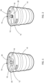
- FIGS. 1 and 2 Overviews of two nonlimiting embodiments of automatic identification and pairing authentication systems are represented in FIGS. 1 and 2 .
- the systems are represented as comprising a keg identification (ID) unit 16 integrated onto the keg 10 in the vicinity of the neck 12 of the keg 10 in which the opening (bung) of the keg 10 is disposed, and a pairing device 18 integrated onto the tap 14 installed in the opening of the keg 10.
- ID unit 16 of FIG. 1 is represented as being mounted on the end wall 20 of the keg 10 in which the neck 12 is formed, and as completely and continuously encircling the neck 12.
- the ID unit 16 of FIG. 2 is represented as mounted directly on and around the perimeter of the neck 12 and completely and continuously encircling the neck 12.
- each ID unit 16 may comprise one or more short-range wireless identification (ID) devices 26 that are packaged or embedded within a housing or enclosure 32.
- ID devices 26 create a field that may encompass the entire perimeter of the neck 12 or up to and including the entire end wall 20 of the keg 10. If the ID unit 16 comprises multiple ID devices 26, the ID devices 26 may be spaced apart from each other within the enclosure 32.
- the enclosure 32 may include openings or channels to allow any contents of the keg 10 that leak or spill to be able to pass behind, beneath, or through the enclosure 32 and not accumulate behind or above the enclosure 32, as would be the case if the end wall 20 slopes downward from the neck 12.
- the taps 14 are represented in FIGS. 1 and 2 as each having a handle 24 that contains the pairing device 18 or to which the pairing device 18 is otherwise mounted, for example, below the handle 24 as shown, or above or to one side of the handle 24.
- the pairing devices 18 function as authentication units to confirm the identity of its respective keg 10 through its associated ID unit 16.
- the pairing devices each include a receiver for receiving short-range wireless information from one or more short-range wireless ID devices 26 of the ID unit 16.
- the wireless information is a short-range wireless transmission such as a near-field RF (also known as inductively coupled) link such as low-frequency (LF) or high-frequency (HF) radio identification device, in which case the one or more ID devices 26 of the ID unit 16 are radio-frequency identification (RFID) devices (discussed in reference to FIGS. 3A, 3B , 4A, and 4B ).
- RFID radio-frequency identification
- the short-range wireless information may be an image transmitted by an optical/vision link, for example, as a result of the one or more short-range wireless ID devices 26 of the ID unit 16 comprising barcodes (discussed in reference to FIGS. 5A and 5B ).
- the ID devices 26 of the ID unit 16 are acoustic or vibration devices that transmit unique acoustic or vibration signals that can be detected by a microphone or accelerometer associated with the pairing device 18.
- the reliability of automatic ID pairing between the ID units 16 and pairing devices 18 described above is obtained by using a short-range wireless information link between the ID unit 16 located on the keg 10 and the pairing device 18 located on the tap 14 to reduce the likelihood of crosstalk between pairing devices 18 and the ID units 16 of adjacent kegs 10.
- the embodiments of automatic identification and pairing authentication systems represented in the drawings utilize short-range wireless ID devices 26 with sufficiently short-range wireless transmission capabilities so that a pairing device 18 mounted on a tap 14 does not automatically identify and pair with a second keg that is immediately adjacent and possibly even abutting the keg 10 on which the tap 14 is installed.
- Reliability of the automatic ID pairing between an ID unit 16 and pairing device 18 is promoted as a result of the ID unit 16 surrounding the opening of the keg 10, such that the pairing device 18 is never misaligned with the ID unit 16 and instead the unit 16 is always in proximity to its pairing device 18 regardless of the rotational position of the pairing device 18 on the keg 10, a situation that inherently occurs due to the rotational position of the tap 14 relative to the keg 10 varying depending on the start and end of the thread turns that secure the tap 14 to the keg 10.
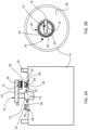
- FIGS. 3A and 3B represent an embodiment in which short-range wireless transmission is utilized and based on inductive-coupling as a result of the short-range wireless ID device 26 of the ID unit 16 comprising a single RFID device 26 with which the pairing device 18 is able to inductively couple.
- Examples of international standardized links are low-frequency (LF) (125-134 kHz) such as ISO 11784/5 and ISO 14223, and high-frequency (HF) (13.56 MHZ) such as ISO15693 and NFC.
- the RFID device 26 comprises an RFID chip 28 connected to an antenna 30, both of which are encased or enclosed in a housing or enclosure 32.
- the antenna 30 may be a multi-turn coil shown as encompassing the entire perimeter of the keg neck 12.
- the pairing device 18 comprises, as a receiver, an RFID reader (interrogator) 34 and an interrogator antenna 36, for example, a multi-turn square or circular winding coil, which for improved operation is placed at the bottom of the pairing device 18 facing the antenna 30 of the ID device 26.
- the antenna 30 is packaged or embedded within the enclosure 32 so that a gap 38 filled with air or a dielectric material is present between the antenna 30 and the surface of the end wall 20 of the keg 10, which is ordinarily formed of steel, aluminum, or possibly another metal.
- the gap 38 provides a better path for the RF field of the interrogator antenna 36 that intersects the antenna 30, as needed for its operation.
- the antenna 30 may have various forms and its radius may be such that it is directly below the interrogator antenna 36 as shown in FIGS. 3A and 3B , though it is foreseeable that the antenna 30 may be located radially inward or outward of the antenna 36.
- FIGS. 4A and 4B represent another embodiment in which the ID unit 16 utilizes short-range wireless transmission based on RFID technology, but in this case multiple individual RFID devices (tags) 26 are used whose operations with the pairing device 18 are based on inductive-coupling.
- RFID devices 26 for this purpose include glass-encapsulated LF RFID tags of the types used for animal tracking and small NFC chips and labels with integrated antennae, the latter of which may be folded inside the enclosure 32.
- Each RFID device 26 comprises an RFID chip 28 connected to an antenna 30, both of which are encased or enclosed in the enclosure 32 such that an air or dielectric gap 38 is present between the antenna 30 and the metal surface of the end wall 20.
- the RFID devices 26 are distributed along the perimeter of the keg neck 12 to provide distributed coverage around the entire neck 12 and capable of reliably pairing with the interrogator antenna 36 of the pairing device 18 mounted to the tap handle 24, regardless of the rotational position of the handle 24 relative to the keg neck 12.
- FIGS. 5A and 5B represent an embodiment in which the short-range wireless information is an image transmitted by an optical/vision link based on optics as a result of the short-range wireless ID device 26 of the ID unit 16 comprising one or more optical ID devices and the link between the ID devices 26 and pairing device 18 being established optically (i.e., vision).
- FIGS. 5A and 5B show such an embodiment in which multiple individual optical devices 26 each comprise a two-dimensional barcode 28 embedded in a translucent enclosure 32 that renders the barcodes 28 not visible or at least not readily visible to the human eye, but is visible to, as a nonlimiting example, an infrared camera module 42 as the receiver of the pairing device 18 mounted to the tap handle 24.
- the pairing device 18 further includes a lens 44 that, depending on the rotational position of the tap 14, is able to capture and read at least one of the barcodes 28. The image of the barcode 28 can then be decoded at the pairing device 18 or transmitted to a remote device for further processing and pairing.
- the RFID and optical links of the embodiments of FIGS. 4A, 4B , 5A , and 5C may be replaced with an acoustic or vibration link, in which the short-range wireless ID devices 26 of their ID units 16 are acoustic or vibration-producing ID devices that transmit a unique acoustic or vibration signal that can be detected by a microphone or accelerometer associated with the pairing device 18 in place of the RFID reader (interrogator) 34 and camera module 42.
- the above embodiments are all preferably capable of operating without requiring a battery for powering the ID unit 16 mounted to the keg 10. This is desirable due to cost and to mitigate any concerns regarding high temperature exposure during washing and cleaning the keg 10. Even so, it is foreseeable that a battery-powered ID unit 16 could be used, as a nonlimiting example, battery-assisted RFID tag(s).
- the pairing device 18 integrated with the tap 14 identifies the keg 10 by interrogating the ID device(s) 26 of its ID unit 16.
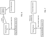
- the ID unit 16 transmits an ID code associated with the keg 10 to the pairing device 18, after which the pairing device 18 may compare the code with a digitally pre-stored set of valid ID codes in an on-board memory device to make the authentication, or the pairing device 18 may transmit the ID code of the keg 10 and its own ID code to a network gateway (as shown in FIG. 6 ) or directly to a remote data server (as illustrated in FIG. 7 ).
- a local wireless link can be realized by a low-power local wireless network such as Bluetooth, WiFi, or proprietary wireless.
- the embodiment shown in FIG. 7 requires a wide-area wireless link such as cellular or LoRa.
- the cloud data servers of FIGS. 6 and 7 may include the digitally pre-stored set of valid ID codes of any number of kegs 10, as well as data related to any number of taps 14 including their assigned locations, and performs the pairing authentication using software.
- the cloud data sever may also include a user dashboard and business rules engine that, depending on its settings, may issue alerts via a software dashboard or by email, an SMS text message, or an automated phone call. Alternatively or in addition, cloud data sever may issue reports and take actions such as shutting down the tap 14 if it includes an internal valve that can be actuated with a solenoid or other suitable device.
- the pairing device 18 optionally but preferably is battery powered, and therefore the electronic components of the device 18 are preferably designed to be power efficient to increase battery life.
- FIG. 8 is a block diagram of the pairing device 18 with various functional block options.
- the device 18 may employ trigger sensors capable of triggering the pairing device 18 to power up and operate only when an action or sequence of actions occurs, such as activating the tap 14 by pressing the tap handle 24, and/or when certain motions or orientation profiles are observed.
- the device 18 is also shown as including a microcontroller and memory, which may have different degrees of capability and size to perform simple functions such as storing the set of valid ID codes and performing basic system operation commands, to having a dynamic database of valid keg ID codes and performing authentication and pairing. Complex operations increase the battery draw and increase the complexity and cost of the pairing device 18, which may not be preferred for some situations.
- the pairing device 18 may also generate an alert if an authentication failure occurs. Such an alert may be performed locally by including a speaker as part of the device 18 for emitting a buzzer or other audible alert, performed remotely at a remote server, or both. Other actions in the case of lack of authentication may include shutting off an electronic valve within the tap 14.
- the pairing device 18 may also include a flowmeter to monitor and measure the beer usage, manage keg replacement, billing, and operational data analytics or control beer flow through a valve within the tap 14, and may close the valve in the event that the tap 14 is incorrectly paired with a keg.
- the microcontroller includes a real-time clock used to record time and location of incorrect pairing of the tap 14 with a non-original keg.
- Location information of the pairing device 18 may be derived from a network gateway ( FIG. 6 ), cellular triangulation ( FIG. 7 ), time-location history, etc.
- Communications between the ID device 26, pairing device 18, and a server may also be used to provide automatic identification of kegs and taps in a keg supply chain, including with respect to factory cleaning, refilling, transportation, and storage. Though the features described above may be desirable for many applications, the pairing device 18 is not required to include all of the various functional blocks represented in FIG. 8 .
- the invention encompasses additional or alternative embodiments in which one or more features or aspects of a particular embodiment could be eliminated or two or more features or aspects of different described embodiments could be combined. Accordingly, it should be understood that the invention is not necessarily limited to any particular embodiment represented in the drawings or described herein, and that the purpose of the above detailed description and the phraseology and terminology employed therein is to describe the particular embodiments represented in the drawings, and not necessarily to serve as limitations to the scope of the invention. Therefore, the scope of the invention is to be limited only by the following claims.
Landscapes
- Engineering & Computer Science (AREA)
- Physics & Mathematics (AREA)
- General Physics & Mathematics (AREA)
- Signal Processing (AREA)
- Computer Networks & Wireless Communication (AREA)
- Theoretical Computer Science (AREA)
- Artificial Intelligence (AREA)
- Toxicology (AREA)
- General Health & Medical Sciences (AREA)
- Computer Vision & Pattern Recognition (AREA)
- Electromagnetism (AREA)
- Health & Medical Sciences (AREA)
- Business, Economics & Management (AREA)
- Emergency Management (AREA)
- Mobile Radio Communication Systems (AREA)
- Multimedia (AREA)
Description
- The present invention generally relates to systems, devices, and methods that are capable of accurately identifying and verifying the proper pairing of kegs and taps.
- Draft beer and other malt beverages (hereinafter, collectively referred to as beer) are commonly available in kegs ("on tap") when sold in bars, restaurants, and other points of sale. Draft beer is popular for its higher quality and in some cases a larger serving size compared with the same beer served in a bottle or can at the same price. Kegs are tapped with a tap that mounts to the opening (bung) of the keg, typically formed in a neck (collar) that protrudes from one end of the keg. Taps are often manufactured to indicate a beer manufacturer's brand, beer style, etc., so that a specific tap can be installed on a keg and used to identify the beer contained in the keg.
- Kegs are often stored in a dedicated storage area or room and retrieved as needed to serve customers. Assuring that a tap installed on a keg correctly identifies the beer contained in the keg, referred to herein as pairing, is important since at the point of dispensing of the beer only the tap identifies the beer. On occasion, due to unintentional or intentional errors, a specific branded beer tap may be installed on a non-matching keg, in other words, incorrectly paired because the contents of the keg do not match the beer brand indicated by the tap. In such cases, a lower priced or grade of beer may be served through a branded tap, which defrauds the customer and damages the beer manufacturer's brand if a lower quality beer is dispensed.
- There are several technologies that are capable of providing automatic identification (ID) for purposes of monitoring and verifying proper pairing of a keg and tap. The keg and tap can each be equipped with an electronic ID device that enables pairing authentication performed by an electronic device integrated with the tap and/or placed in the keg storage room or other remote location. The electronic device communicates with the keg and tap electronic ID devices through a wireless or possibly a wired link. For practical considerations and ease of operation, it is preferred to have a non-contact or wireless data link between the keg and tap electronic ID devices regardless of where their pairing authentication is performed. One approach is to use wireless devices with far-field radio frequency (RF) data-link connectivity. The challenge with application of this technology is the likelihood of crosstalk between kegs that are adjacent to each in the same storage or tapping area. To address this issue, an automatic ID device (tag) that utilizes a non-contact data link technology having a limited range, as nonlimiting examples, devices that utilize acoustic, near-field radio frequency (RF) including inductively or capacitively coupled wireless, or optical/vision technologies, can be integrated with a keg along with a keg auto-identification (auto-ID) receiving device integrated with the tap as an add-on module attached to the exterior of the tap or embedded within the handle of the tap. However, because taps are typically threaded onto a keg, when a tap is installed on a keg the rotational position of the tap relative to the keg will vary depending on the start and end of the thread turns. This variation in the position (or relative location) of the auto-ID receiving device integrated onto a tap may result in a longer distance to the tag integrated onto the keg, which may make the pairing error rate non-negligible and unacceptable depending on the position of the tap.
- The subject matter of this invention includes systems, devices, and methods that are capable of accurately identifying and verifying the proper pairing of kegs and taps regardless of the position of a tap relative to a keg on which it is installed.
- According to one aspect of the invention, an automatic identification and pairing authentication system is provided that comprises an identification (ID) unit integrated onto a keg and a pairing device integrated onto a tap, wherein the ID unit and the pairing device communicate through a wireless connection.
- According to another aspect of the invention, an automatic identification and pairing authentication system for pairing a keg with a tap installed on the keg includes an identification unit compromising at least a first short-range wireless identification device integrated onto an end wall of the keg, and a pairing device on the tap and comprising a receiver for receiving short-range wireless information from the first short-range wireless ID device of the identification unit. The short-range wireless identification device surrounds an opening of the keg in which the tap is installed so that the pairing device identifies and verifies pairing of the keg and the tap regardless of a rotational position of the tap relative to the keg.
- According to yet another aspect of the invention, a method of automatically identifying and pairing a keg with a tap installed on the keg includes using at least a first short-range wireless ID device associated with an identification unit to provide short-range wireless information, and using a pairing device on the tap to receive the short-range wireless information from the first short-range wireless ID device. The first short-range wireless identification device is integrated onto an end wall of a keg, and identifying and verifying pairing of the keg and the tap is performed with the pairing device regardless of a rotational position of the tap relative to the keg.
- Technical aspects of systems, devices, and methods having features as described above preferably include the ability for a tap to identify a keg on which it is installed for purposes of identifying the contents within the keg, with reduced likelihood of crosstalk with adjacent kegs. Such a capability is advantageous when performing automatic identification and pairing of kegs with their corresponding taps in a restaurant or bar setting. The systems, devices, and methods help to prevent errors or misuses if a tap is installed on a keg whose contents do not match the identify of the beverage associated with the tap. The systems, devices, and methods are capable of providing high accuracy of authentication, while optionally providing additional functionality for actions or data capture when a tap is paired with a keg and activated.
- Other aspects and advantages of this invention will be appreciated from the following detailed description.
-
-
FIGS. 1 and 2 schematically represent automatic identification and pairing authentication systems comprising an identification (ID) unit integrated onto a keg in the vicinity of the opening (bung) of the keg, and a pairing device integrated onto a tap installed on the opening of the keg in accordance with nonlimiting embodiments of the invention. -
FIGS. 3A and 3B schematically represent a nonlimiting embodiment of an automatic identification and pairing authentication system comprising a keg ID unit integrated onto a keg and a pairing device integrated onto a tap installed on the keg, wherein the ID unit comprises a single RFID device with an antenna that encircles the entire opening of the keg. -
FIGS. 4A and 4B schematically represent a nonlimiting embodiment of an automatic identification and pairing authentication system comprising a keg ID unit integrated onto a keg and a pairing device integrated onto a tap installed on the keg, wherein the ID unit comprises multiple RFID devices spaced apart in an enclosure that encircles the opening of the keg. -
FIGS. 5A and 5B schematically represent a nonlimiting embodiment of an automatic identification and pairing authentication system comprising a keg ID unit integrated onto a keg and a pairing device integrated onto a tap installed on the keg, wherein the ID unit comprises multiple two-dimensional (2D) barcodes spaced apart in an enclosure that encircles the opening of the keg. -
FIG. 6 is a flow chart representing a pairing device connected to a remote data server through a wireless network gateway. -
FIG. 7 is a flow chart representing a pairing device directly connected to a remote data server through a wide-area wireless link. -
FIG. 8 is a block diagram representing components of a pairing device capable of use in any of the embodiments ofFIGS. 1 through 7 . - The following disclosure describes various aspects of systems, devices, and methods schematically represented in
FIGS. 1 through 8 and adapted to accurately identify and verify the proper pairing of kegs and taps regardless of the position of the tap relative to a keg on which it is installed. Physical embodiments of systems and devices represented inFIGS. 1 through 5 are shown as used in association withkegs 10 having a generally common configuration, in which eachkeg 10 has an opening (bung) to which atap 14 can be mounted to dispense the contents of thekeg 10, and each opening is represented as formed in a neck (collar) 12 that protrudes from one end of thekeg 10. While thekegs 10 are believed to be of a conventional form, the systems and devices described herein can be used with kegs having configurations other than what is shown inFIGS. 1 through 5 . - Overviews of two nonlimiting embodiments of automatic identification and pairing authentication systems are represented in
FIGS. 1 and 2 . In each ofFIGS. 1 and 2 , the systems are represented as comprising a keg identification (ID)unit 16 integrated onto thekeg 10 in the vicinity of theneck 12 of thekeg 10 in which the opening (bung) of thekeg 10 is disposed, and apairing device 18 integrated onto thetap 14 installed in the opening of thekeg 10. TheID unit 16 ofFIG. 1 is represented as being mounted on theend wall 20 of thekeg 10 in which theneck 12 is formed, and as completely and continuously encircling theneck 12. TheID unit 16 ofFIG. 2 is represented as mounted directly on and around the perimeter of theneck 12 and completely and continuously encircling theneck 12. TheID unit 16 ofFIG. 1 and/or 2 may be separately manufactured and then permanently attached to itskeg 10, though it is foreseeable that portions of theunits 16 could be incorporated directly into the design of thekeg 10. As discussed below in reference toFIGS. 3A through 5B , eachID unit 16 may comprise one or more short-range wireless identification (ID)devices 26 that are packaged or embedded within a housing orenclosure 32. TheID devices 26 create a field that may encompass the entire perimeter of theneck 12 or up to and including theentire end wall 20 of thekeg 10. If theID unit 16 comprisesmultiple ID devices 26, theID devices 26 may be spaced apart from each other within theenclosure 32. Theenclosure 32 may include openings or channels to allow any contents of thekeg 10 that leak or spill to be able to pass behind, beneath, or through theenclosure 32 and not accumulate behind or above theenclosure 32, as would be the case if theend wall 20 slopes downward from theneck 12. - The
taps 14 are represented inFIGS. 1 and 2 as each having ahandle 24 that contains thepairing device 18 or to which thepairing device 18 is otherwise mounted, for example, below thehandle 24 as shown, or above or to one side of thehandle 24. Thepairing devices 18 function as authentication units to confirm the identity of itsrespective keg 10 through itsassociated ID unit 16. The pairing devices each include a receiver for receiving short-range wireless information from one or more short-rangewireless ID devices 26 of theID unit 16. In some embodiments, the wireless information is a short-range wireless transmission such as a near-field RF (also known as inductively coupled) link such as low-frequency (LF) or high-frequency (HF) radio identification device, in which case the one ormore ID devices 26 of theID unit 16 are radio-frequency identification (RFID) devices (discussed in reference toFIGS. 3A, 3B ,4A, and 4B ). Alternatively the short-range wireless information may be an image transmitted by an optical/vision link, for example, as a result of the one or more short-rangewireless ID devices 26 of theID unit 16 comprising barcodes (discussed in reference toFIGS. 5A and 5B ). It is noted that other short-range wireless information links could be employed, as nonlimiting examples, acoustic or vibration links or capacitive coupling between theID units 16 andpairing device 18. In the case of an acoustic or vibration link, theID devices 26 of theID unit 16 are acoustic or vibration devices that transmit unique acoustic or vibration signals that can be detected by a microphone or accelerometer associated with thepairing device 18. - The reliability of automatic ID pairing between the
ID units 16 andpairing devices 18 described above is obtained by using a short-range wireless information link between theID unit 16 located on thekeg 10 and thepairing device 18 located on thetap 14 to reduce the likelihood of crosstalk betweenpairing devices 18 and theID units 16 ofadjacent kegs 10. In particular, the embodiments of automatic identification and pairing authentication systems represented in the drawings utilize short-rangewireless ID devices 26 with sufficiently short-range wireless transmission capabilities so that apairing device 18 mounted on atap 14 does not automatically identify and pair with a second keg that is immediately adjacent and possibly even abutting thekeg 10 on which thetap 14 is installed. Reliability of the automatic ID pairing between anID unit 16 andpairing device 18 is promoted as a result of theID unit 16 surrounding the opening of thekeg 10, such that thepairing device 18 is never misaligned with theID unit 16 and instead theunit 16 is always in proximity to itspairing device 18 regardless of the rotational position of thepairing device 18 on thekeg 10, a situation that inherently occurs due to the rotational position of thetap 14 relative to thekeg 10 varying depending on the start and end of the thread turns that secure thetap 14 to thekeg 10. -
FIGS. 3A and 3B represent an embodiment in which short-range wireless transmission is utilized and based on inductive-coupling as a result of the short-rangewireless ID device 26 of theID unit 16 comprising asingle RFID device 26 with which thepairing device 18 is able to inductively couple. Examples of international standardized links are low-frequency (LF) (125-134 kHz) such as ISO 11784/5 and ISO 14223, and high-frequency (HF) (13.56 MHZ) such as ISO15693 and NFC. TheRFID device 26 comprises anRFID chip 28 connected to anantenna 30, both of which are encased or enclosed in a housing orenclosure 32. Theantenna 30 may be a multi-turn coil shown as encompassing the entire perimeter of thekeg neck 12. Thepairing device 18 comprises, as a receiver, an RFID reader (interrogator) 34 and aninterrogator antenna 36, for example, a multi-turn square or circular winding coil, which for improved operation is placed at the bottom of thepairing device 18 facing theantenna 30 of theID device 26. Theantenna 30 is packaged or embedded within theenclosure 32 so that agap 38 filled with air or a dielectric material is present between theantenna 30 and the surface of theend wall 20 of thekeg 10, which is ordinarily formed of steel, aluminum, or possibly another metal. Thegap 38 provides a better path for the RF field of theinterrogator antenna 36 that intersects theantenna 30, as needed for its operation. Theantenna 30 may have various forms and its radius may be such that it is directly below theinterrogator antenna 36 as shown inFIGS. 3A and 3B , though it is foreseeable that theantenna 30 may be located radially inward or outward of theantenna 36. -
FIGS. 4A and 4B represent another embodiment in which theID unit 16 utilizes short-range wireless transmission based on RFID technology, but in this case multiple individual RFID devices (tags) 26 are used whose operations with thepairing device 18 are based on inductive-coupling. Nonlimiting embodiments ofRFID devices 26 for this purpose include glass-encapsulated LF RFID tags of the types used for animal tracking and small NFC chips and labels with integrated antennae, the latter of which may be folded inside theenclosure 32. EachRFID device 26 comprises anRFID chip 28 connected to anantenna 30, both of which are encased or enclosed in theenclosure 32 such that an air ordielectric gap 38 is present between theantenna 30 and the metal surface of theend wall 20. TheRFID devices 26 are distributed along the perimeter of thekeg neck 12 to provide distributed coverage around theentire neck 12 and capable of reliably pairing with theinterrogator antenna 36 of thepairing device 18 mounted to thetap handle 24, regardless of the rotational position of thehandle 24 relative to thekeg neck 12. -
FIGS. 5A and 5B represent an embodiment in which the short-range wireless information is an image transmitted by an optical/vision link based on optics as a result of the short-rangewireless ID device 26 of theID unit 16 comprising one or more optical ID devices and the link between theID devices 26 andpairing device 18 being established optically (i.e., vision).FIGS. 5A and 5B show such an embodiment in which multiple individualoptical devices 26 each comprise a two-dimensional barcode 28 embedded in atranslucent enclosure 32 that renders thebarcodes 28 not visible or at least not readily visible to the human eye, but is visible to, as a nonlimiting example, aninfrared camera module 42 as the receiver of thepairing device 18 mounted to thetap handle 24. Thepairing device 18 further includes alens 44 that, depending on the rotational position of thetap 14, is able to capture and read at least one of thebarcodes 28. The image of thebarcode 28 can then be decoded at thepairing device 18 or transmitted to a remote device for further processing and pairing. - The RFID and optical links of the embodiments of
FIGS. 4A, 4B ,5A , and 5C may be replaced with an acoustic or vibration link, in which the short-rangewireless ID devices 26 of theirID units 16 are acoustic or vibration-producing ID devices that transmit a unique acoustic or vibration signal that can be detected by a microphone or accelerometer associated with thepairing device 18 in place of the RFID reader (interrogator) 34 andcamera module 42. - The above embodiments are all preferably capable of operating without requiring a battery for powering the
ID unit 16 mounted to thekeg 10. This is desirable due to cost and to mitigate any concerns regarding high temperature exposure during washing and cleaning thekeg 10. Even so, it is foreseeable that a battery-poweredID unit 16 could be used, as a nonlimiting example, battery-assisted RFID tag(s). - In the embodiments described above and shown in the drawings, the
pairing device 18 integrated with thetap 14 identifies thekeg 10 by interrogating the ID device(s) 26 of itsID unit 16. TheID unit 16 transmits an ID code associated with thekeg 10 to thepairing device 18, after which thepairing device 18 may compare the code with a digitally pre-stored set of valid ID codes in an on-board memory device to make the authentication, or thepairing device 18 may transmit the ID code of thekeg 10 and its own ID code to a network gateway (as shown inFIG. 6 ) or directly to a remote data server (as illustrated inFIG. 7 ). In the embodiment shown inFIG. 6 , a local wireless link can be realized by a low-power local wireless network such as Bluetooth, WiFi, or proprietary wireless. The embodiment shown inFIG. 7 requires a wide-area wireless link such as cellular or LoRa. - The cloud data servers of
FIGS. 6 and 7 may include the digitally pre-stored set of valid ID codes of any number ofkegs 10, as well as data related to any number oftaps 14 including their assigned locations, and performs the pairing authentication using software. The cloud data sever may also include a user dashboard and business rules engine that, depending on its settings, may issue alerts via a software dashboard or by email, an SMS text message, or an automated phone call. Alternatively or in addition, cloud data sever may issue reports and take actions such as shutting down thetap 14 if it includes an internal valve that can be actuated with a solenoid or other suitable device. - As represented by the nonlimiting embodiment of
FIG. 8 , thepairing device 18 optionally but preferably is battery powered, and therefore the electronic components of thedevice 18 are preferably designed to be power efficient to increase battery life.FIG. 8 is a block diagram of thepairing device 18 with various functional block options. For example, in addition to an RFID reader (interrogator) 34 orcamera module 42, thedevice 18 may employ trigger sensors capable of triggering thepairing device 18 to power up and operate only when an action or sequence of actions occurs, such as activating thetap 14 by pressing thetap handle 24, and/or when certain motions or orientation profiles are observed. Thedevice 18 is also shown as including a microcontroller and memory, which may have different degrees of capability and size to perform simple functions such as storing the set of valid ID codes and performing basic system operation commands, to having a dynamic database of valid keg ID codes and performing authentication and pairing. Complex operations increase the battery draw and increase the complexity and cost of thepairing device 18, which may not be preferred for some situations. Thepairing device 18 may also generate an alert if an authentication failure occurs. Such an alert may be performed locally by including a speaker as part of thedevice 18 for emitting a buzzer or other audible alert, performed remotely at a remote server, or both. Other actions in the case of lack of authentication may include shutting off an electronic valve within thetap 14. Such actions require two-way communications between thepairing device 18 and a server if a pairing check is performed remotely or additional server verification is required. Thepairing device 18 may also include a flowmeter to monitor and measure the beer usage, manage keg replacement, billing, and operational data analytics or control beer flow through a valve within thetap 14, and may close the valve in the event that thetap 14 is incorrectly paired with a keg. In some embodiments the microcontroller includes a real-time clock used to record time and location of incorrect pairing of thetap 14 with a non-original keg. Location information of thepairing device 18 may be derived from a network gateway (FIG. 6 ), cellular triangulation (FIG. 7 ), time-location history, etc. Communications between theID device 26,pairing device 18, and a server may also be used to provide automatic identification of kegs and taps in a keg supply chain, including with respect to factory cleaning, refilling, transportation, and storage. Though the features described above may be desirable for many applications, thepairing device 18 is not required to include all of the various functional blocks represented inFIG. 8 . - While the invention has been described in terms of particular embodiments, it should be apparent that alternatives could be adopted by one skilled in the art. For example, the automatic identification and pairing authentication systems, its ID and
pairing devices devices
Claims (15)
- An automatic identification and pairing authentication system for pairing a keg (10) with a tap (14) installed on the keg (10), the keg (10) having an end wall (20) surrounding an opening of the keg (10) in which the tap (14) is installed, the system comprising:an identification unit (16) compromising at least a first short-range wireless identification device (26) integrated onto the end wall (20) of a keg (10), the short-range wireless identification device (26) surrounding the opening of the keg (10) in which the tap (14) is installed; anda pairing device (18) on the tap (14), the pairing device (18) comprising a receiver (34,42) for receiving short-range wireless information from the first short-range wireless ID device (26) of the identification unit (16);wherein the short-range wireless identification device (26) surrounds the opening of the keg (10) so that the pairing device (18) identifies and verifies pairing of the keg (10) and the tap (14) regardless of a rotational position of the tap (14)relative to the keg (10).
- The automatic identification and pairing authentication system in claim 1, wherein the first short-range wireless identification device (26) is within an enclosure (32) and encircles the opening on the end wall (20) of the keg (10).
- The automatic identification and pairing authentication system in claim 1, wherein the first short-range wireless identification device (26) is one of a plurality of short-range wireless identification devices (26) within an enclosure (32).
- The automatic identification and pairing authentication system in claim 3, wherein the enclosure (32) is on the end wall (20) of the keg (10) and the plurality of short-range wireless identification devices (26) encircle the opening of the keg (10); or wherein the enclosure (32) is on a neck (12) of the keg (10) in which the opening of the keg (10) is disposed and the plurality of short-range wireless identification devices (26) encircle the opening of the keg (10).
- The automatic identification and pairing authentication system of claim 1, wherein the short-range wireless information is a near-field radio frequency transmission, and the first short-range wireless identification device (26) is a radio-frequency identification device (26) that is inductively coupled to the pairing device (18), optionallywherein the first short-range wireless identification device (26) is within an enclosure (32) and an air or dielectric gap is between the first short-range wireless identification device (26) and the end wall (20) of the keg (10), or optionally wherein the first short-range wireless identification device (26) comprises a single antenna (30) that encircles the opening on the end wall (20) of the keg (10), or optionallywherein the first short-range wireless identification device (26) is one of a plurality of short-range wireless identification devices (26) that each comprise an antenna (30).
- The automatic identification and pairing authentication system of claim 1, wherein the short-range wireless information is an image and the first short-range wireless identification device (26) is optically linked to the pairing device (18), optionally wherein the first short-range wireless identification device (26) is a barcode.
- The automatic identification and pairing authentication system of claim 6, wherein the pairing device (18) comprises a camera (42) and the first short-range wireless identification device (26) is one of a plurality of short-range wireless identification devices (26) within a translucent enclosure (32) that encircles the opening of the keg (10).
- The automatic identification and pairing authentication system of claim 7, wherein the camera (32) is an infrared camera, or wherein the first short-range wireless ID device (26) is an acoustic or vibration- producing device.
- The automatic identification and pairing authentication system of claim 1, wherein the pairing device (18) performs the identifying and verifying of the pairing of the keg (10) and the tap (14).
- The automatic identification and pairing authentication system of claim 1, further comprising a remote data server, wherein the pairing device (18) wirelessly communicates with the remote data server to identify and verify pairing of the keg (10) and the tap (14), optionally further comprising a gateway to which the pairing device (18) is wireless linked, and the gateway is connected to the remote data server.
- The automatic identification and pairing authentication system of claim 1, wherein the pairing device (18) further comprises a flowmeter that monitors and
measures flow through the tap (14) of a beverage contained in the keg (10), optionally wherein the pairing device (18) controls the flow of the beverage through a valve within the tap (14). - The automatic identification and pairing authentication system of claim 1, wherein the pairing device (18) further comprises:i) trigger sensors that detect activation of the tap (14) and initiating of pairing of the tap (14) and the keg (10);ii) means for generating an alert; oriii) a real-time clock that records time of activation of the tap (14) and/or initiation of pairing of the tap (14) and the keg (10).
- A method of automatically identifying and pairing a keg (10) with a tap (14) installed on the keg (10), the keg (10) having an end wall (20) surrounding an opening of the keg (10) in which the tap (14) is installed, the method comprising:using at least a first short-range wireless ID device (26) associated with an identification unit (16) to provide short-range wireless information, the first short-range wireless identification device (26) being integrated onto the end wall (20) of a keg (10);using a pairing device (18) on the tap (14) to receive the short-range wireless information from the first short-range wireless ID device (26); andidentifying and verifying pairing of the keg (10) and the tap (14) with the pairing device (18) regardless of a rotational position of the tap (14) relative to the keg (10).
- The method of claim 13, wherein the keg (10) contains a beverage and the pairing device (18) measures and controls flow of the beverage through a valve of the tap (14).
- The method in claim 13, wherein the pairing device (18):i) closes the valve if the tap (14) is incorrectly paired with the keg (10);ii) generates an alert if the tap (14) is incorrectly paired with the keg (10); oriii) stores and wirelessly transmits activation of the tap (14) and/or initiation of pairing of the tap (14) and the keg (10).
Applications Claiming Priority (3)
| Application Number | Priority Date | Filing Date | Title |
|---|---|---|---|
| US201962905405P | 2019-09-25 | 2019-09-25 | |
| US17/029,292 US11498826B2 (en) | 2019-09-25 | 2020-09-23 | Systems, devices, and methods for pairing kegs and taps |
| PCT/US2020/052469 WO2021061965A1 (en) | 2019-09-25 | 2020-09-24 | Systems, devices, and methods for pairing kegs and taps |
Publications (4)
| Publication Number | Publication Date |
|---|---|
| EP4035076A1 EP4035076A1 (en) | 2022-08-03 |
| EP4035076A4 EP4035076A4 (en) | 2023-10-18 |
| EP4035076C0 EP4035076C0 (en) | 2025-01-01 |
| EP4035076B1 true EP4035076B1 (en) | 2025-01-01 |
Family
ID=74881740
Family Applications (1)
| Application Number | Title | Priority Date | Filing Date |
|---|---|---|---|
| EP20868869.7A Active EP4035076B1 (en) | 2019-09-25 | 2020-09-24 | Systems, devices, and methods for pairing kegs and taps |
Country Status (3)
| Country | Link |
|---|---|
| US (1) | US11498826B2 (en) |
| EP (1) | EP4035076B1 (en) |
| WO (1) | WO2021061965A1 (en) |
Families Citing this family (2)
| Publication number | Priority date | Publication date | Assignee | Title |
|---|---|---|---|---|
| TWI776498B (en) * | 2021-05-07 | 2022-09-01 | 啓碁科技股份有限公司 | Antenna system |
| CZ2024268A3 (en) * | 2024-07-01 | 2025-04-30 | Sanixera S.R.O. | System for monitoring operating parameters and location of beverage kegs |
Family Cites Families (22)
| Publication number | Priority date | Publication date | Assignee | Title |
|---|---|---|---|---|
| CA2414870A1 (en) | 2002-12-20 | 2004-06-20 | Labatt Brewing Company Limited | Beverage dispensing system and apparatus |
| US20080195251A1 (en) | 2004-08-25 | 2008-08-14 | Andrew Milner | Beverage Control System |
| US7113125B2 (en) * | 2004-12-16 | 2006-09-26 | International Business Machines Corporation | Method for measuring material level in a container using RFID tags |
| WO2006066338A1 (en) * | 2004-12-22 | 2006-06-29 | Barilliant Systems Pty Limited | Dispensing systems |
| US9652707B2 (en) * | 2006-10-31 | 2017-05-16 | Fiber Mountain, Inc. | Radio frequency identification (RFID) connected tag communications protocol and related systems and methods |
| US7864041B2 (en) * | 2007-11-28 | 2011-01-04 | Carefusion 303, Inc. | Active-tag based dispensing |
| WO2010093747A2 (en) | 2009-02-11 | 2010-08-19 | Pepsico, Inc. | Beverage dispense valve controlled by wireless technology |
| US20120059513A1 (en) * | 2010-09-03 | 2012-03-08 | Shannon Perkins | Beverage dispensing and monitoring system |
| US9221667B2 (en) | 2012-05-24 | 2015-12-29 | SteadyServ Technologies, LLC | Draft beer supply chain systems and methods |
| US20140327524A1 (en) * | 2013-05-02 | 2014-11-06 | Wal-Mart Stores, Inc. | Method and apparatus pertaining to preconfiguring in facilitating the reading of rfid tags |
| US9993934B2 (en) | 2014-03-07 | 2018-06-12 | Hyperthem, Inc. | Liquid pressurization pump and systems with data storage |
| EP2993928B1 (en) * | 2014-09-04 | 2017-11-01 | Nokia Technologies OY | Device selection to establish a wireless communication |
| WO2016089389A1 (en) | 2014-12-03 | 2016-06-09 | Kevin Beal | System and process for measuring a volume of a liquid within a keg |
| US20160296810A1 (en) * | 2015-04-10 | 2016-10-13 | Vattaca, LLC | Authentication Tags and Systems for Golf Clubs |
| US20180272240A1 (en) * | 2015-12-23 | 2018-09-27 | Amazon Technologies, Inc. | Modular interaction device for toys and other devices |
| US20170210610A1 (en) * | 2016-01-22 | 2017-07-27 | Zachary William Henson | Beverage dispensing apparatus for measuring flow and reducing foaming in dispensing systems |
| US10315906B1 (en) * | 2016-03-21 | 2019-06-11 | Beverage Design, Llc | Wireless beverage dispensing monitor |
| US9830800B2 (en) * | 2016-03-31 | 2017-11-28 | Intel Corporation | Early warning of non-compliance with an established workflow in a work area |
| US10810387B2 (en) * | 2018-07-30 | 2020-10-20 | Hand Held Products, Inc. | Method, system and apparatus for locating RFID tags |
| US11353662B2 (en) * | 2019-04-26 | 2022-06-07 | Hewlett Packard Enterprise Development Lp | Smart carriers and smart adapters for automatic discovery of fiber assemblies |
| US11638587B2 (en) * | 2019-06-28 | 2023-05-02 | Cilag Gmbh International | RFID identification systems for surgical instruments |
| US20210081891A1 (en) * | 2019-09-17 | 2021-03-18 | Altair Engineering, Inc. | Systems and Methods for Tracking Beer Kegs and other Fluid Vessels |
-
2020
- 2020-09-23 US US17/029,292 patent/US11498826B2/en active Active
- 2020-09-24 WO PCT/US2020/052469 patent/WO2021061965A1/en not_active Ceased
- 2020-09-24 EP EP20868869.7A patent/EP4035076B1/en active Active
Also Published As
| Publication number | Publication date |
|---|---|
| US20210087044A1 (en) | 2021-03-25 |
| EP4035076C0 (en) | 2025-01-01 |
| US11498826B2 (en) | 2022-11-15 |
| WO2021061965A1 (en) | 2021-04-01 |
| EP4035076A1 (en) | 2022-08-03 |
| EP4035076A4 (en) | 2023-10-18 |
Similar Documents
| Publication | Publication Date | Title |
|---|---|---|
| US12291443B2 (en) | Beverage dispense valve controlled by wireless technology | |
| ES3060213T3 (en) | Methods and devices for fuel dispenser electronic communication | |
| US7746228B2 (en) | Passive container tracking device, system, and method | |
| US6026868A (en) | Transponder distinction in a fueling environment | |
| US8374789B2 (en) | Systems and methods for using marking information to electronically display dispensing of markers by a marking system or marking tool | |
| US8310379B2 (en) | Monitoring device for a tracking system | |
| US9334150B1 (en) | Smart container dispenser and tracking system | |
| EP2264642B1 (en) | Data exchange with a man-machine-device using short range radio communication | |
| US20140174568A1 (en) | Draft beer supply chain system and method | |
| US9026041B2 (en) | Portable radio-frequency repeater | |
| US11498826B2 (en) | Systems, devices, and methods for pairing kegs and taps | |
| US20080094211A1 (en) | Id proximity monitoring of inventory objects | |
| CA2572956A1 (en) | Methods and systems for automating inventory and dispatch procedures at a staging area | |
| KR20190086450A (en) | Dispensing station and dispensing system | |
| US20200095111A1 (en) | Systems, methods, devices and uses thereof for monitoring tap handles and bottles | |
| KR101707979B1 (en) | Integrated platform system using beacon | |
| KR20180055515A (en) | Cold water purifier capable of automatic ordering of water bottles and delivery method of the water bottles | |
| KR20190051408A (en) | Gas container dispensing monitoring system suitable for things internet environment | |
| US20070205203A1 (en) | Method, apparatus, and system for monitoring amount of liquid poured from liquid containers | |
| CN113116152B (en) | Monitoring system and monitoring method for barreled water dispenser | |
| WO2017048454A1 (en) | Inventory management system | |
| KR20200087360A (en) | Use Management System of Refractories Using Improved RFID |
Legal Events
| Date | Code | Title | Description |
|---|---|---|---|
| STAA | Information on the status of an ep patent application or granted ep patent |
Free format text: STATUS: THE INTERNATIONAL PUBLICATION HAS BEEN MADE |
|
| PUAI | Public reference made under article 153(3) epc to a published international application that has entered the european phase |
Free format text: ORIGINAL CODE: 0009012 |
|
| STAA | Information on the status of an ep patent application or granted ep patent |
Free format text: STATUS: REQUEST FOR EXAMINATION WAS MADE |
|
| 17P | Request for examination filed |
Effective date: 20220329 |
|
| AK | Designated contracting states |
Kind code of ref document: A1 Designated state(s): AL AT BE BG CH CY CZ DE DK EE ES FI FR GB GR HR HU IE IS IT LI LT LU LV MC MK MT NL NO PL PT RO RS SE SI SK SM TR |
|
| DAV | Request for validation of the european patent (deleted) | ||
| DAX | Request for extension of the european patent (deleted) | ||
| REG | Reference to a national code |
Ref legal event code: R079 Free format text: PREVIOUS MAIN CLASS: G06K0019077000 Ipc: G06K0017000000 Ref country code: DE Ref document number: 602020044269 Country of ref document: DE |
|
| A4 | Supplementary search report drawn up and despatched |
Effective date: 20230918 |
|
| RIC1 | Information provided on ipc code assigned before grant |
Ipc: H04W 4/80 20180101ALI20230912BHEP Ipc: H04W 84/18 20090101ALI20230912BHEP Ipc: B67D 1/08 20060101ALI20230912BHEP Ipc: G06K 19/077 20060101ALI20230912BHEP Ipc: G06K 17/00 20060101AFI20230912BHEP |
|
| GRAP | Despatch of communication of intention to grant a patent |
Free format text: ORIGINAL CODE: EPIDOSNIGR1 |
|
| STAA | Information on the status of an ep patent application or granted ep patent |
Free format text: STATUS: GRANT OF PATENT IS INTENDED |
|
| INTG | Intention to grant announced |
Effective date: 20240816 |
|
| GRAS | Grant fee paid |
Free format text: ORIGINAL CODE: EPIDOSNIGR3 |
|
| GRAA | (expected) grant |
Free format text: ORIGINAL CODE: 0009210 |
|
| STAA | Information on the status of an ep patent application or granted ep patent |
Free format text: STATUS: THE PATENT HAS BEEN GRANTED |
|
| P01 | Opt-out of the competence of the unified patent court (upc) registered |
Free format text: CASE NUMBER: APP_59193/2024 Effective date: 20241030 |
|
| AK | Designated contracting states |
Kind code of ref document: B1 Designated state(s): AL AT BE BG CH CY CZ DE DK EE ES FI FR GB GR HR HU IE IS IT LI LT LU LV MC MK MT NL NO PL PT RO RS SE SI SK SM TR |
|
| REG | Reference to a national code |
Ref country code: GB Ref legal event code: FG4D |
|
| REG | Reference to a national code |
Ref country code: CH Ref legal event code: EP |
|
| REG | Reference to a national code |
Ref country code: DE Ref legal event code: R096 Ref document number: 602020044269 Country of ref document: DE |
|
| REG | Reference to a national code |
Ref country code: IE Ref legal event code: FG4D |
|
| U01 | Request for unitary effect filed |
Effective date: 20250203 |
|
| P04 | Withdrawal of opt-out of the competence of the unified patent court (upc) registered |
Free format text: CASE NUMBER: APP_11426/2025 Effective date: 20250308 |
|
| U07 | Unitary effect registered |
Designated state(s): AT BE BG DE DK EE FI FR IT LT LU LV MT NL PT RO SE SI Effective date: 20250312 |
|
| PG25 | Lapsed in a contracting state [announced via postgrant information from national office to epo] |
Ref country code: PL Free format text: LAPSE BECAUSE OF FAILURE TO SUBMIT A TRANSLATION OF THE DESCRIPTION OR TO PAY THE FEE WITHIN THE PRESCRIBED TIME-LIMIT Effective date: 20250101 |
|
| PG25 | Lapsed in a contracting state [announced via postgrant information from national office to epo] |
Ref country code: ES Free format text: LAPSE BECAUSE OF FAILURE TO SUBMIT A TRANSLATION OF THE DESCRIPTION OR TO PAY THE FEE WITHIN THE PRESCRIBED TIME-LIMIT Effective date: 20250101 |
|
| PG25 | Lapsed in a contracting state [announced via postgrant information from national office to epo] |
Ref country code: NO Free format text: LAPSE BECAUSE OF FAILURE TO SUBMIT A TRANSLATION OF THE DESCRIPTION OR TO PAY THE FEE WITHIN THE PRESCRIBED TIME-LIMIT Effective date: 20250401 Ref country code: IS Free format text: LAPSE BECAUSE OF FAILURE TO SUBMIT A TRANSLATION OF THE DESCRIPTION OR TO PAY THE FEE WITHIN THE PRESCRIBED TIME-LIMIT Effective date: 20250501 |
|
| PG25 | Lapsed in a contracting state [announced via postgrant information from national office to epo] |
Ref country code: HR Free format text: LAPSE BECAUSE OF FAILURE TO SUBMIT A TRANSLATION OF THE DESCRIPTION OR TO PAY THE FEE WITHIN THE PRESCRIBED TIME-LIMIT Effective date: 20250101 |
|
| PG25 | Lapsed in a contracting state [announced via postgrant information from national office to epo] |
Ref country code: GR Free format text: LAPSE BECAUSE OF FAILURE TO SUBMIT A TRANSLATION OF THE DESCRIPTION OR TO PAY THE FEE WITHIN THE PRESCRIBED TIME-LIMIT Effective date: 20250402 |
|
| PG25 | Lapsed in a contracting state [announced via postgrant information from national office to epo] |
Ref country code: CZ Free format text: LAPSE BECAUSE OF FAILURE TO SUBMIT A TRANSLATION OF THE DESCRIPTION OR TO PAY THE FEE WITHIN THE PRESCRIBED TIME-LIMIT Effective date: 20250101 |
|
| PG25 | Lapsed in a contracting state [announced via postgrant information from national office to epo] |
Ref country code: SM Free format text: LAPSE BECAUSE OF FAILURE TO SUBMIT A TRANSLATION OF THE DESCRIPTION OR TO PAY THE FEE WITHIN THE PRESCRIBED TIME-LIMIT Effective date: 20250101 |
|
| PGFP | Annual fee paid to national office [announced via postgrant information from national office to epo] |
Ref country code: GB Payment date: 20250926 Year of fee payment: 6 |
|
| PG25 | Lapsed in a contracting state [announced via postgrant information from national office to epo] |
Ref country code: SK Free format text: LAPSE BECAUSE OF FAILURE TO SUBMIT A TRANSLATION OF THE DESCRIPTION OR TO PAY THE FEE WITHIN THE PRESCRIBED TIME-LIMIT Effective date: 20250101 |
|
| U20 | Renewal fee for the european patent with unitary effect paid |
Year of fee payment: 6 Effective date: 20250926 |
|
| PLBE | No opposition filed within time limit |
Free format text: ORIGINAL CODE: 0009261 |
|
| STAA | Information on the status of an ep patent application or granted ep patent |
Free format text: STATUS: NO OPPOSITION FILED WITHIN TIME LIMIT |
|
| REG | Reference to a national code |
Ref country code: CH Ref legal event code: L10 Free format text: ST27 STATUS EVENT CODE: U-0-0-L10-L00 (AS PROVIDED BY THE NATIONAL OFFICE) Effective date: 20251112 |
|
| 26N | No opposition filed |
Effective date: 20251002 |
|
| REG | Reference to a national code |
Ref country code: CH Ref legal event code: H13 Free format text: ST27 STATUS EVENT CODE: U-0-0-H10-H13 (AS PROVIDED BY THE NATIONAL OFFICE) Effective date: 20260504 |